EP4234859B1 - Fahrzeugtürgriffanordnung - Google Patents
Fahrzeugtürgriffanordnung Download PDFInfo
- Publication number
- EP4234859B1 EP4234859B1 EP22191999.6A EP22191999A EP4234859B1 EP 4234859 B1 EP4234859 B1 EP 4234859B1 EP 22191999 A EP22191999 A EP 22191999A EP 4234859 B1 EP4234859 B1 EP 4234859B1
- Authority
- EP
- European Patent Office
- Prior art keywords
- lever
- extremity
- vehicle door
- handle
- bracket
- Prior art date
- Legal status (The legal status is an assumption and is not a legal conclusion. Google has not performed a legal analysis and makes no representation as to the accuracy of the status listed.)
- Active
Links
Images



Classifications
-
- E—FIXED CONSTRUCTIONS
- E05—LOCKS; KEYS; WINDOW OR DOOR FITTINGS; SAFES
- E05B—LOCKS; ACCESSORIES THEREFOR; HANDCUFFS
- E05B85/00—Details of vehicle locks not provided for in groups E05B77/00 - E05B83/00
- E05B85/10—Handles
- E05B85/107—Pop-out handles, e.g. sliding outwardly before rotation
-
- E—FIXED CONSTRUCTIONS
- E05—LOCKS; KEYS; WINDOW OR DOOR FITTINGS; SAFES
- E05B—LOCKS; ACCESSORIES THEREFOR; HANDCUFFS
- E05B77/00—Vehicle locks characterised by special functions or purposes
- E05B77/42—Means for damping the movement of lock parts, e.g. slowing down the return movement of a handle
-
- E—FIXED CONSTRUCTIONS
- E05—LOCKS; KEYS; WINDOW OR DOOR FITTINGS; SAFES
- E05B—LOCKS; ACCESSORIES THEREFOR; HANDCUFFS
- E05B85/00—Details of vehicle locks not provided for in groups E05B77/00 - E05B83/00
- E05B85/10—Handles
- E05B85/103—Handles creating a completely closed wing surface
-
- E—FIXED CONSTRUCTIONS
- E05—LOCKS; KEYS; WINDOW OR DOOR FITTINGS; SAFES
- E05B—LOCKS; ACCESSORIES THEREFOR; HANDCUFFS
- E05B85/00—Details of vehicle locks not provided for in groups E05B77/00 - E05B83/00
- E05B85/10—Handles
- E05B85/14—Handles pivoted about an axis parallel to the wing
- E05B85/16—Handles pivoted about an axis parallel to the wing a longitudinal grip part being pivoted at one end about an axis perpendicular to the longitudinal axis of the grip part
Definitions
- the present invention relates to a vehicle door assembly, in particular of the type with a handle translating from a rest position where the handle is retracted and a deployed position where the handle is deployed and can be taken in hand and opened.
- Document KR 102 104 888 B1 discloses such a vehicle door assembly with a translating handle moved by a motor.
- One aim of the present invention is to find an economic and mechanical alternative for vehicle door handle assemblies having a translative movement.
- the invention as defined by claim 1 relates to a vehicle door handle assembly comprising a bracket and a handle, said handle comprising a first extremity and a second extremity opposed to the first extremity, the first extremity being connected to a first lever, said first lever being designed to be connected to an opening lever to open a latch of the vehicle door, said first lever being designed to rotate between a rest position where the first extremity of the handle is in a rest position, a deployed position where the first extremity of the handle is in a deployed position outside the bracket and an opening position where the first lever actuates the opening lever,
- the second extremity being connected to a second lever, said second lever being designed to rotate between a rest position where the second extremity of the handle is a rest position, an activation position where the second extremity of the handle lowers the second lever into the bracket, and a deployed position where the second extremity of the handle is in a deployed position outside the bracket,
- the vehicle door handle assembly also comprising a return lever having a first extremity connected to the second lever, said return lever being designed to rotate between a first position and a second position, the return lever comprising an elastic mean passively bringing back said return lever to its first position, the rotation of the second lever to its activation position actuates the rotation of the return lever from its first to its second position, and the passive rotation of the return lever from its second to its first position actuates the rotation of the second lever from its deployed position to its rest position.
- the return lever may be connected to a delay element which slows down the passive rotation of the return lever from its second to its first position.
- the delay element may comprise at least one damper.
- the at least one damper may comprise a gearwheel and a second extremity of the return lever connected to the at least one damper may comprise an arc portion with teeth engaged with said gearwheel.
- the second extremity of the return lever connected to the at least one damper may comprise a portion without teeth in order to disconnect the return lever of the at least one damper before the said return lever reaches its first position.
- the first lever may comprise an elastic mean passively bringing back said first lever from its deployed position to its rest position.
- the second lever may comprise an elastic mean passively rotating said second lever toward its deployed position.
- connection between the first lever and the first extremity of the handle may be a pivot-slide connection.
- the first and second levers may be connected together with at least one first rod, said first rod transmitting the rotation of the second lever from its activation position to its deployed position to the first lever, rotating said first lever from its rest position to its deployed position.
- the first rod may comprise a pivot-slide connection with anyone of the first or second lever so that the first lever can rotate from its rest position to its deployed position or from its deployed position to its opening position without rotating the second lever.
- the second and the return levers are connected together by a second and a third rods, said second rod transmitting the rotation of the second lever from its rest position to its activation position to the return lever, rotating said return lever from its first position to its second position, said third rod transmitting the rotation of the return lever from its second position to its first position to the second lever, rotating said second lever from its deployed position to its rest position.
- the second rod may comprise a pivot-slide connection with anyone of the second or return lever.
- the third rod comprises a pivot-slide connection with anyone of the second or return lever.
- the handle may be configured to be pushed into the bracket for lowering the second lever in activation position.
- the handle may be configured to move in a rectilinear manner when pushing the handle into the bracket.
- the handle is considered as a whole to be pushed by the user into the bracket. There is no rotation of the handle when a user is pushing on the handle.
- the handle may be configured to abut on a rest portion of the bracket in the activation position, the handle being distant from said rest portion when the first lever and second lever are both in rest position.
- the handle may present an external side facing the outside of the bracket; any part of the external side being configured to be pushed towards the bracket for lowering the second lever in activation position.
- the handle may include a leg linking the first extremity and the second extremity.
- the leg, the first extremity and the second extremity are each presenting a corresponding portion of the external side.
- the external side may present a contour corresponding to a contour on an opening of the bracket that receives the handle. Preferably, both contours merge in rest position of the first lever and second lever.
- the second extremity of the handle may be configured to be pushed into the bracket for lowering the second lever in activation position.
- the user activates the handle by pushing the second extremity of the handle into the bracket.
- the handle may be configured to rotate taking support on a rest portion of the bracket, the first extremity of the handle (2) protrudes from the bracket and rotates the first lever around its pivot connection with the bracket from its rest position to an intermediate position.
- the rest portion is placed between the first and second extremities of the handle.
- the rotation of the first lever is not transmitted to the second lever by the first rod due to the pivot-slide connection of the first rod with anyone of the first or second lever.
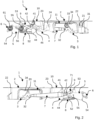
- FIGS 1 and 2 show a vehicle door handle assembly 1 in a rest position.
- the vehicle door handle assembly 1 comprises a bracket 10 and a handle 2.
- the bracket 10 is designed to be fixed on the vehicle door (not represented). In this rest position, the handle 2 is retracted into the bracket 10 in order to be at the same level of the door body when installed.
- the handle 2 comprises a first extremity 22 and a second extremity 23 opposed to the first extremity 22.
- the first extremity 22 of the handle 2 is connected to a first lever 3 and the second extremity 23 of the handle 2 is connected to a second lever 4.
- the first lever 3 is also designed to be connected to an opening lever (not represented) to open a latch of the vehicle door.
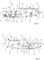
- the first lever 3 is designed to rotate between a rest position (represented in figures 1 and 2 ) where the first extremity 22 of the handle 2 is in a rest position, a deployed position (represented in figures 3 to 6 ) where the first extremity 22 of the handle 2 is in a deployed position outside the bracket 10 and an opening position (represented on figures 7 and 8 ) where the first lever 3 actuates the opening lever.
- the first lever 3 comprises a pivot connection 33 with the bracket 10 around which the first lever 3 rotates between its different positions.
- a first extremity of the first lever 3 is connected to the first extremity 22 of the handle 2 and a second extremity of the first lever 3, is connected to the opening lever, in particular, thanks to a pivot connection 31 and the shape of the first lever 3, the first lever 3 can touch the opening lever during the movement.
- the connection between the first lever 3 and the first extremity 22 of the handle is preferably a pivot-slide connection.
- the first extremity 22 of the handle 2 comprises a slide opening 21 and the first lever 3 comprises a recess 31 for example to receive a pin (not represented).
- the first lever 3 may also comprises an elastic mean 34 passively bringing back said first lever 3 from its deployed position to its rest position.
- This elastic mean 34 may be a spring positioned for example on the pivot connection 33 between the first lever 3 and the bracket 10.
- the torque applied by this elastic mean 34 is represented by a grey arrow in figures 1 to 8 .
- the second extremity 23 of the handle 2 is connected to a second lever 4.
- the second lever 4 is designed to rotate between a rest position (represented in figures 1 and 2 ) where the second extremity 23 of the handle 2 is in a rest position, an activation position (represented in figures 3 and 4 and 10 according to an alternative) where the second extremity 23 of the handle 2 lowers the second lever 4 into the bracket 10, and a deployed position (represented in figures 5 to 8 ) where the second extremity 23 of the handle 2 is in a deployed position outside the bracket 10.
- the second lever 4 comprises a pivot connection 41 with the bracket 10 around which the second lever 4 rotates between its different positions.
- a first extremity of the second lever 4 is connected to the second extremity 23 of the handle 2.
- This connection is preferably a pivot connection 24.
- the second lever 4 may also comprises an elastic mean (not represented) passively rotating said second lever 4 to its deployed position.
- This elastic mean may be a spring positioned for example on the pivot connection 41 between the second lever 4 and the bracket 10.
- the torque applied by this elastic mean is represented by a grey arrow in figures 1 to 8 .
- the first 3 and second 4 levers may be connected together with at least one first rod 7 in order to synchronize the movements of the two levers 3, 4. More exactly, the first rod 7 transmits the rotation of the second lever 4 from its activation position to its deployed position to the first lever 3, rotating said first lever 3 from its rest position to its deployed position.
- the first rod 7 may comprises a pivot-slide connection with anyone of the first 3 or second lever 4 so that the first lever 3 can rotate from its rest position to its deployed position or from its deployed position to its opening position without rotating the second lever 4.
- the first rod 7 comprises a first extremity connected to a second extremity of the first lever 3 by a pivot connection 32.
- the first rod 7 comprises a second extremity connected to the second lever 4 by pivot-slide connection.
- the second extremity of the first rod 7 comprises a slide 71 and the second extremity of the second lever 4 comprises a pin 42 inserted into said slide 71.
- the handle 2, the first lever 3, the second 4 lever and the first rod 7 are designed and connected like a parallelogram and move together synchronously.
- the other connection of the first rod 7 with anyone of the first 3 or second lever 4 is preferably a pivot connection.
- the vehicle door handle assembly 1 also comprises a return lever 5 having a first extremity connected to a second extremity of the second lever 4, said return lever 5 being designed to rotate between a first position (represented in figures 1 and 2 ) and a second position (represented in figures 3 to 8 ). More precisely, the return lever 5 comprises a pivot connection 55 with the bracket 10 around which the return lever 5 rotates between its different positions.
- the return lever 5 also comprises an elastic mean 56 passively bringing back said return lever 5 to its first position.
- This elastic mean 56 may be a spring positioned for example on the pivot connection 55 between the return lever 5 and the bracket 10. The torque applied by this elastic mean 56 is represented by a grey arrow on figures 1 to 8 .
- the rotation of the second lever 4 to its activation position actuates the rotation of the return lever 5 from its first to its second position.
- the passive rotation of the return lever 5 from its second to its first position actuates the rotation of the second lever 4 from its deployed position to its rest position.
- the second 4 and the return 5 levers are connected together by a second 8 and a third 9 rods.
- the second rod 8 transmits the rotation of the second lever 4 from its rest position to its activation position to the return lever 5, rotating said return lever 5 from its first position to its second position.
- the third rod 9 transmits the rotation of the return lever 5 from its second position to its first position to the second lever 4, rotating said second lever 4 from its deployed position to its rest position.
- the second 8 and the third 9 rods are placed on the return lever 5 on either side of the pivot connection 55 of the return lever 5 with the bracket 10.
- the second 8 and the third 9 rods are placed on the first extremity of second lever 5 on the same side of the pivot connection 41 of the second lever 4 with the bracket 10.
- the second rod 8 may comprises a pivot-slide connection 52 with anyone of the second lever 4 or return lever 5.
- the pivot-slide connection 52 is placed between the return lever 5 and the second rod 8.
- the return lever 5 comprises the slide of said pivot-slide connection 52 and the second rod 8 comprises a pin inserted in the slide.
- the connection between the second rod 8 and the second lever 4 is a pivot connection 44.
- the other connection of the second rod 8 with any of the second lever 4 or return lever 5 is preferably a pivot connection.
- the third rod 9 may comprises a pivot-slide connection 45 with any of the second lever 4 or return lever 5.
- the pivot-slide connection 45 is placed between the second lever 4 and the third rod 9.
- the second lever 4 comprises the slide of said pivot-slide connection 45 and the third rod 9 comprises a pin inserted in the slide.
- the connection between the third rod 9 and the return lever 5 is a pivot connection 53.
- the other connection of the third rod 9 with any of the second lever 4 or return lever 5 is preferably a pivot connection.
- the return lever 5, more exactly its second extremity, is connected to a delay element 6 which slows down the passive rotation of the return lever 5 from its second to its first position.
- This delay element 6 may comprises at least one damper as illustrated in figures 1 to 8 .
- the at least one damper 6 may comprises a gearwheel 61 and the extremity of the return lever 5, connected to the at least one damper 6, comprises an arc portion with teeth 54 engaged with said gearwheel 61.
- the torque applied by this at least one damper 6 is represented by a grey arrow on figures 1 to 8 .
- the figures 1 to 8 represent different positions and cinematic steps of the deployment, opening and retraction of the handle 2.
- figures 1 and 2 are a representation of a rest position where the handle 2 is retracted into the bracket 10 in order to be at the same level of the door body when installed.
- the first lever 3 is in its rest position and maintained in this rest position by the elastic mean 34.
- the second lever 4 is in its rest position and the return lever 5 is in its first position.
- the return lever 5 is maintained in its first position by the elastic mean 56.
- the elastic mean 56 of the return lever 5 is stronger than the elastic mean of the second lever 4 in order that the return lever 5 in its first position maintained the second lever 4 in its rest position.
- the elastic mean 56 of the return lever 5 is also stronger than the delay element 6 in order to maintain the return lever 5 in its first position.
- the inside of the handle 2 may also rests on a rest portion 11 of the bracket 10 placed between the first 22 and second 23 extremities of the handle 2.
- Figures 3 and 4 represent an activation position of the handle 2 according to an activation by rotation alternative where the user activates the handle 2 by pushing the second extremity 23 of the handle 2 into the bracket 10. Due to this push, the handle 2 rotates taking support on the rest portion 11 of the bracket 10. The first extremity 22 of the handle 2 protrudes from the bracket 10 and rotates the first lever 3 around its pivot connection 33 with the bracket 10 from its rest position to an intermediate. The rotation of the first lever 3 is not transmitted to the second lever 4 by the first rod 7 due to the pivot-slide connection of the first rod 7 with anyone of the first 3 or second lever 4.
- the push of the second extremity 23 of the handle 2 rotates the second lever 4 around its pivot connection 41 with the bracket 10 from its rest position to its activation position.
- the rotation of the second lever 4 causes the rotation of the return lever 5 around its pivot connection 55 with the bracket 10 from its first to its second position.
- the transmission of the rotation of the second lever 4 to the return lever 5 is made by the second rod 8 which pushes one side of the return lever 5 causing its rotation.
- the rotation of the second lever 4 to its activation position makes the second rod 8 slid in its slide-pivot connection with anyone of the second 4 or return lever 5 bringing the second rod 8 to abutment pushing the return lever 5.
- the third rod 9 slides in its slide-pivot connection with anyone of the second lever 4 or return lever 5 without affecting the rotation of anyone of these levers 4, 5.
- the rotation of the second lever 4 is made against the torque of its elastic mean and the rotation of the return lever 5 is made against the torque of its elastic mean 56.
- Figure 10 presents an activation by translation alternative, wherein there is an activation clearance 12 within the bracket 10 so that the handle 2 can be moved in a rectilinear manner from its rest position to the activation position as depicted.
- the handle 2 is pushed into the bracket for lowering the second lever 4 in activation position.
- the handle 2 moves in a rectilinear manner when pushing the handle into the bracket 10.
- the handle is considered as a whole to be pushed by the user into the bracket.
- the handle 2 is configured to abut on the rest portion 11 of the bracket 10 in the activation position, the handle 2 being distant from said rest portion 11 when the first lever 3 and second lever 4 are both in rest position.
- the handle 2 presents an external side 26 facing the outside of the bracket 10; any part of the external side 26 being configured to be pushed towards the bracket 10 for lowering the second lever 4 in activation position.
- the handle includes a leg 25 linking the first extremity and the second extremity.
- the leg 25, the first extremity and the second extremity are each presenting a corresponding portion of the external side 26.
- the external side 26 may present a contour corresponding to a contour on an opening of the bracket that receives the handle.
- both contours merge in rest position of the first lever and second lever. In other words, in rest position, both contours are at a corresponding level transversally to an extension plan of the external side 26.
- Figures 5 and 6 represent a deployed position of the handle 2 where the first lever 3 is still in its deployed position and where the second lever 4 has rotated from its activation position to its deployed position, bringing the second extremity 23 of the handle 2 in its deployed position outside the bracket 10.
- the elastic mean of the second lever 4 allows the passive rotation of the second lever 4 to its deployed position.
- the rotation of the second lever 4 is not transmitted to the return lever 5 by any of the second 8 or third rod 9 which slide with their pivot-slide connections.
- the first lever 3 is maintained in its deployed position due to the first rod 7 which is in abutment with its pivot-slide connection.
- the return lever 5 is still on its second position due to the delay element 6.
- the third rod 9 is in abutment in order to stop the rotation of the second lever 4 in its deployed position against the torque of its elastic mean 34.
- Figures 7 and 8 represent an opening position of the handle where the user can grab the handle and pull it or has taken the handle and pulled it in order to open the vehicle door.
- the handle 2 rotates around the pivot connection 24 between the second extremity 23 of the handle 2 and the second lever 4.
- the first extremity 22 of the handle 2 is pulled in an opening position rotating the first lever 3 from its deployed position to its opening position.
- the rotation of the first lever 3 is not transmitted to the second lever 4 by the first rod 7 due to its pivot-slide connection.
- the first lever 3 rotates back to its deployed position due to its elastic mean 34.
- the delay element 6 slows down the passive return rotation of the return lever 5 from its second position to its first position.
- the return lever 5 rotates from its second to its first position, it also transmits its rotation to the second lever 4 in order to rotate the second lever 4 from its deployed position to its rest position.
- the third rod 9 is in abutment in order to pull back the second lever 4 in its rest position against the torque of the elastic mean of the second lever4.
- the rotation of the second 4 and the first 3 levers to their rest position are synchronous due to the first rod 7.
- the handle 2 translates from its deployed position ( figures 5 and 6 ) to its rest position ( figures 1 and 2 ). This translation is slowed down and progressive thanks to the delay element 6.
- the extremity of the return lever 5 connected to the at least one damper 6 may comprises a portion without teeth 54 in order to disconnect the return lever 5 of the at least one damper 6 before said return lever 5 reaches its first position.
- This embodiment allows accelerating the return of the return lever 5 at the end and so accelerating the translation of the handle 2 from its deployed position to its rest position when the handle 2 is near its rest position.
Landscapes
- Lock And Its Accessories (AREA)
Claims (19)
- Fahrzeugtürgriffbaugruppe (1), umfassend eine Halterung (10) und einen Griff (2), wobei der Griff (2) ein erstes Ende (22) und ein zweites Ende (23) gegenüber dem ersten Ende (22) umfasst,wobei das erste Ende (22) mit einem ersten Hebel (3) verbunden ist, wobei der erste Hebel (3) ausgebildet ist, um mit einem Öffnungshebel verbunden zu sein, um eine Verriegelung der Fahrzeugtür zu öffnen, wobei der erste Hebel (3) ausgebildet ist, um sich zwischen einer Ruheposition, in der sich das erste Ende (22) des Griffs (2) in einer Ruheposition befindet, einer ausgefahrenen Position, in der sich das erste Ende (22) des Griffs (2) in einer ausgefahrenen Position außerhalb der Halterung (10) befindet, und einer Öffnungsposition, in der der erste Hebel (3) den Öffnungshebel betätigt, zu drehen,wobei das zweite Ende (23) mit einem zweiten Hebel (4) verbunden ist, wobei der zweite Hebel (4) ausgebildet ist, um sich zwischen einer Ruheposition, in der das zweite Ende (23) des Griffs (2) eine Ruheposition ist, einer Aktivierungsposition, in der das zweite Ende (23) des Griffs (2) den zweiten Hebel (4) in die Halterung (10) absenkt, und einer ausgefahrenen Position, in der das zweite Ende (23) des Griffs (2) in einer ausgefahrenen Position außerhalb der Halterung (10) ist, zu drehen,wobei die Fahrzeugtürgriffbaugruppe (1) ferner einen Rückführhebel (5) umfasst, der ein erstes Ende aufweist, das mit dem zweiten Hebel (4) verbunden ist, wobei der Rückführhebel (5) ausgebildet ist, um sich zwischen einer ersten Position und einer zweiten Position zu drehen, wobei der Rückführhebel (5) ein elastisches Mittel (56) umfasst, das den Rückführhebel (5) passiv in seine erste Position zurückbringt,wobei die Drehung des zweiten Hebels (4) in seine Aktivierungsposition die Drehung des Rücklaufhebels (5) von seiner ersten in seine zweite Position bewirkt, und die passive Drehung des Rücklaufhebels (5) von seiner zweiten in seine erste Position die Drehung des zweiten Hebels (4) von seiner ausgefahrenen Position in seine Ruheposition bewirkt,wobei der zweite Hebel (4) und der Rückführhebel (5) durch eine zweite (8) und eine dritte (9) Stange miteinander verbunden sind, wobei die zweite Stange (8) die Drehung des zweiten Hebels (4) von seiner Ruheposition in seine Aktivierungsposition an den Rückführhebel (5) überträgt, wobei der Rückführhebel (5) von seiner ersten Position in seine zweite Stellung gedreht wird, wobei die dritte Stange (9) die Drehung des Rückführhebels (5) von seiner zweiten Position in seine erste Position an den zweiten Hebel (4) überträgt, wobei der zweite Hebel (4) von seiner ausgefahrenen Position in seine Ruheposition gedreht wird.
- Fahrzeugtürgriffbaugruppe (1) nach dem vorhergehenden Anspruch, wobei der Rückführhebel (5) mit einem Verzögerungselement (6) verbunden ist, das die passive Drehung des Rückführhebels (5) von seiner zweiten in seine erste Position verlangsamt.
- Fahrzeugtürgriffbaugruppe (1) nach dem vorhergehenden Anspruch, wobei das Verzögerungselement (6) mindestens einen Dämpfer umfasst.
- Fahrzeugtürgriffbaugruppe (1) nach dem vorhergehenden Anspruch, wobei der mindestens eine Dämpfer (6) ein Zahnrad (61) umfasst und wobei ein zweites Ende des mit dem mindestens einen Dämpfer (6) verbundenen Rückführhebels (5) einen Bogenabschnitt mit Zähnen (54) umfasst, die mit dem Zahnrad (61) in Eingriff stehen.
- Fahrzeugtürgriffbaugruppe (1) nach dem vorhergehenden Anspruch, wobei das zweite Ende des mit dem mindestens einen Dämpfer (6) verbundenen Rückführhebels (5) einen Abschnitt ohne Zähne (54) umfasst, um den Rückführhebel (5) des mindestens einen Dämpfers (6) zu trennen, bevor der Rückführhebel (5) seine erste Position erreicht.
- Fahrzeugtürgriffbaugruppe (1) nach einem der vorhergehenden Ansprüche, wobei der erste Hebel (3) ein elastisches Mittel (34) umfasst, das den ersten Hebel (3) passiv von seiner ausgefahrenen Position in seine Ruheposition zurückbringt.
- Fahrzeugtürgriffbaugruppe (1) nach einem der vorhergehenden Ansprüche, wobei der zweite Hebel (4) ein elastisches Mittel umfasst, das den zweiten Hebel (4) passiv in Richtung seiner ausgefahrenen Position dreht.
- Fahrzeugtürgriffbaugruppe (1) nach einem der vorhergehenden Ansprüche, wobei die Verbindung zwischen dem ersten Hebel (3) und dem ersten Ende (22) des Griffs eine Schwenk-Schiebe-Verbindung ist.
- Fahrzeugtürgriffbaugruppe (1) nach einem der vorhergehenden Ansprüche, wobei der erste (3) und der zweite (4) Hebel mit mindestens einer ersten Stange (7) verbunden sind, wobei die erste Stange (7) die Drehung des zweiten Hebels (4) von seiner Aktivierungsposition in seine ausgefahrene Position auf den ersten Hebel (3) überträgt, wobei der erste Hebel (3) von seiner Ruheposition in seine ausgefahrene Position gedreht wird.
- Fahrzeugtürgriffbaugruppe (1) nach dem vorhergehenden Anspruch, wobei die erste Stange (7) eine Schwenk-Schiebe-Verbindung mit einem von dem ersten (3) und dem zweiten Hebel (4) umfasst, so dass sich der erste Hebel (3) von seiner Ruheposition in seine ausgefahrene Position oder von seiner ausgefahrenen Position in seine Öffnungsposition drehen kann, ohne dass der zweite Hebel (4) gedreht wird.
- Fahrzeugtürgriffbaugruppe (1) nach einem der Ansprüche 1 bis 10, wobei die zweite Stange (8) eine Schwenk-Schiebe-Verbindung mit einem von dem zweiten Hebel (4) und dem Rückführhebel (5) umfasst
- Fahrzeugtürgriffbaugruppe (1) nach einem der Ansprüche 1 bis 10, wobei die dritte Stange (9) eine Schwenk-Schiebe-Verbindung mit einem von dem zweiten Hebel (4) und dem Rückführhebel (5) umfasst.
- Fahrzeugtürgriffbaugruppe (1) nach einem der Ansprüche 1 bis 12, wobei der Griff (2) so eingerichtet ist, dass er zum Absenken des zweiten Hebels (4) in die Aktivierungsposition in die Halterung (10) gedrückt wird.
- Fahrzeugtürgriffbaugruppe (1) nach Anspruch 13, wobei der Griff (2) so eingerichtet ist, dass er sich in gerader Weise bewegt, wenn der Griff in die Halterung (10) gedrückt wird.
- Fahrzeugtürgriffbaugruppe (1) nach Anspruch 14, wobei der Griff (2) so eingerichtet ist, dass er in der Aktivierungsposition an einem Ruheabschnitt (11) der Halterung (10) anliegt, wobei der Griff (2) von dem Ruheabschnitt (11) entfernt ist, wenn sich sowohl der erste Hebel (3) als auch der zweite Hebel (4) in der Ruheposition befinden.
- Fahrzeugtürgriffbaugruppe (1) nach einem der Ansprüche 13 bis 15, wobei der Griff (2) eine Außenseite (26) aufweist, die der Außenseite der Halterung (10) zugewandt ist; wobei jeder Teil der Außenseite (26) so eingerichtet ist, dass er zum Absenken des zweiten Hebels (4) in die Aktivierungsposition in Richtung der Halterung (10) gedrückt wird.
- Fahrzeugtürgriffbaugruppe (1) nach einem der Ansprüche 1 bis 12, wobei das zweite Ende (23) des Griffs (2) so eingerichtet ist, dass es zum Absenken des zweiten Hebels (4) in die Aktivierungsposition in die Halterung (10) gedrückt wird.
- Fahrzeugtürgriffbaugruppe (1) nach Anspruch 17, wobei der Griff (2) so eingerichtet ist, dass er sich dreht, indem er sich auf einem Ruheabschnitt (11) der Halterung (10) abstützt, wobei das erste Ende (22) des Griffs (2) aus der Halterung (10) herausragt und den ersten Hebel (3) um seine Schwenkverbindung (33) mit der Halterung (10) von seiner Ruheposition in eine Zwischenposition dreht.
- Fahrzeugtürgriffbaugruppe (1) nach Anspruch 18, wobei, wenn sich sowohl der erste Hebel (3) als auch der zweite Hebel (4) in der Ruheposition befinden, die Innenseite des Griffs (2) auf dem Ruheabschnitt (11) der Halterung (10) aufliegt.
Priority Applications (4)
| Application Number | Priority Date | Filing Date | Title |
|---|---|---|---|
| EP23152938.9A EP4234860B1 (de) | 2022-02-23 | 2023-01-23 | Fahrzeugtürgriffanordnung |
| ES23152938T ES3022683T3 (en) | 2022-02-23 | 2023-01-23 | Vehicle door handle assembly |
| CN202310155971.2A CN116641607A (zh) | 2022-02-23 | 2023-02-23 | 车门把手组件 |
| US18/113,145 US12286821B2 (en) | 2022-02-23 | 2023-02-23 | Vehicle door handle assembly |
Applications Claiming Priority (1)
| Application Number | Priority Date | Filing Date | Title |
|---|---|---|---|
| EP22158287.7A EP4234858B1 (de) | 2022-02-23 | 2022-02-23 | Fahrzeugtürgriffanordnung |
Publications (2)
| Publication Number | Publication Date |
|---|---|
| EP4234859A1 EP4234859A1 (de) | 2023-08-30 |
| EP4234859B1 true EP4234859B1 (de) | 2025-03-19 |
Family
ID=80448623
Family Applications (2)
| Application Number | Title | Priority Date | Filing Date |
|---|---|---|---|
| EP22158287.7A Active EP4234858B1 (de) | 2022-02-23 | 2022-02-23 | Fahrzeugtürgriffanordnung |
| EP22191999.6A Active EP4234859B1 (de) | 2022-02-23 | 2022-08-24 | Fahrzeugtürgriffanordnung |
Family Applications Before (1)
| Application Number | Title | Priority Date | Filing Date |
|---|---|---|---|
| EP22158287.7A Active EP4234858B1 (de) | 2022-02-23 | 2022-02-23 | Fahrzeugtürgriffanordnung |
Country Status (3)
| Country | Link |
|---|---|
| US (1) | US12385298B2 (de) |
| EP (2) | EP4234858B1 (de) |
| CN (1) | CN116641605A (de) |
Families Citing this family (1)
| Publication number | Priority date | Publication date | Assignee | Title |
|---|---|---|---|---|
| US20250215731A1 (en) * | 2023-12-28 | 2025-07-03 | Sl Corporation | Door handle for vehicle |
Family Cites Families (11)
| Publication number | Priority date | Publication date | Assignee | Title |
|---|---|---|---|---|
| US7210716B2 (en) * | 2004-06-03 | 2007-05-01 | Illinois Tool Works Inc. | Movement prevention device |
| DE102013112705A1 (de) * | 2013-11-18 | 2015-05-21 | Illinois Tool Works Inc. | System aus einem Bauteil und einer Betätigungsvorrichtung für das Bauteil |
| GB2536672B (en) * | 2015-03-25 | 2018-04-04 | Jaguar Land Rover Ltd | Rectractable handle arrangement with emergency manual deployment |
| JP6617498B2 (ja) * | 2015-09-28 | 2019-12-11 | アイシン精機株式会社 | 車両用アウトサイドハンドル装置 |
| FR3054260B1 (fr) * | 2016-07-22 | 2018-07-13 | Peugeot Citroen Automobiles Sa | Systeme de commande d’ouverture d’ouvrant de vehicule automobile |
| JP6957390B2 (ja) * | 2018-03-09 | 2021-11-02 | 株式会社アルファ | 車両のドアハンドル装置 |
| US10435924B1 (en) * | 2018-06-26 | 2019-10-08 | Ford Global Technologies, Llc | Vehicle door handle having ice handling |
| KR102621229B1 (ko) * | 2018-08-31 | 2024-01-04 | 현대자동차 주식회사 | 차량용 출몰형 아웃사이드 도어 핸들 조립체 |
| KR102104888B1 (ko) * | 2019-01-24 | 2020-04-27 | 주식회사 프라코 | 차량용 오토 플러쉬 아웃사이드 도어 핸들 조립체 |
| KR20210055107A (ko) * | 2019-10-14 | 2021-05-17 | 주식회사 세화오토모티브 | 차량의 출몰형 아웃사이드 도어 핸들 |
| US11746575B2 (en) * | 2020-07-16 | 2023-09-05 | Magna Mirrors Of America, Inc. | Vehicular door handle with manual override stop |
-
2022
- 2022-02-23 EP EP22158287.7A patent/EP4234858B1/de active Active
- 2022-08-24 EP EP22191999.6A patent/EP4234859B1/de active Active
-
2023
- 2023-02-20 CN CN202310141515.2A patent/CN116641605A/zh active Pending
- 2023-02-23 US US18/173,220 patent/US12385298B2/en active Active
Also Published As
| Publication number | Publication date |
|---|---|
| EP4234858A1 (de) | 2023-08-30 |
| US12385298B2 (en) | 2025-08-12 |
| EP4234859A1 (de) | 2023-08-30 |
| EP4234858B1 (de) | 2025-04-09 |
| CN116641605A (zh) | 2023-08-25 |
| US20230265692A1 (en) | 2023-08-24 |
Similar Documents
| Publication | Publication Date | Title |
|---|---|---|
| CN110626223B (zh) | 一种电动滑轨的离合机构 | |
| FI83802B (fi) | Elektromekaniskt doerrlaos. | |
| JP6629724B2 (ja) | ドアハンドルとドアハンドル用の作動装置とから構成されるシステム | |
| EP3078792B1 (de) | Deckelvorrichtung | |
| EP2585324B1 (de) | Türvorrichtung und verfahren | |
| US7064285B2 (en) | Cover opening and closing mechanism | |
| US6067869A (en) | Actuating assembly for motor-vehicle door latch | |
| EP4234859A1 (de) | Fahrzeugtürgriffanordnung | |
| CN107719677B (zh) | 飞机座椅自动释放装置 | |
| EP4234860B1 (de) | Fahrzeugtürgriffanordnung | |
| KR20110015505A (ko) | 자동 트랜스미션용 파킹 록 시스템 | |
| EP3943695B1 (de) | Handgriff für eine fahrzeugtür | |
| AU2012256283A1 (en) | Electric door operator | |
| EP3604932B1 (de) | Türschlosssystem für ein gerät | |
| WO2011148691A1 (ja) | 電動スライド装置 | |
| EP4414526A1 (de) | Fahrzeugtürgriffanordnung | |
| EP4353931A1 (de) | Fahrzeugtürgriffanordnung mit einem stossdämpfer | |
| EP4414527B1 (de) | Fahrzeugtürgriffanordnung | |
| EP3771790B1 (de) | Schloss | |
| EP2886405A1 (de) | Handbremshebel mit elektrisch betätigtem Sperrmechanismus | |
| EP4407128A1 (de) | Türgriffanordnung für ein elektrofahrzeug | |
| EP4339353A1 (de) | Automatisches öffnungsmodul für eine tür eines haushaltsgeräts | |
| CN111479977B (zh) | 用于机动车辆的把手支撑件 | |
| CN114843126B (zh) | 一种断路器与隔离开关之间的柔性联锁装置及开关柜 | |
| CN110593679A (zh) | 一种用于轨道交通车辆门系统的锁闭机构 |
Legal Events
| Date | Code | Title | Description |
|---|---|---|---|
| PUAI | Public reference made under article 153(3) epc to a published international application that has entered the european phase |
Free format text: ORIGINAL CODE: 0009012 |
|
| STAA | Information on the status of an ep patent application or granted ep patent |
Free format text: STATUS: THE APPLICATION HAS BEEN PUBLISHED |
|
| AK | Designated contracting states |
Kind code of ref document: A1 Designated state(s): AL AT BE BG CH CY CZ DE DK EE ES FI FR GB GR HR HU IE IS IT LI LT LU LV MC MK MT NL NO PL PT RO RS SE SI SK SM TR |
|
| STAA | Information on the status of an ep patent application or granted ep patent |
Free format text: STATUS: REQUEST FOR EXAMINATION WAS MADE |
|
| 17P | Request for examination filed |
Effective date: 20240125 |
|
| RBV | Designated contracting states (corrected) |
Designated state(s): AL AT BE BG CH CY CZ DE DK EE ES FI FR GB GR HR HU IE IS IT LI LT LU LV MC MK MT NL NO PL PT RO RS SE SI SK SM TR |
|
| RIN1 | Information on inventor provided before grant (corrected) |
Inventor name: CITRON, FREDERIC Inventor name: GUERIN, ANTHONY Inventor name: PEYNOT, THOMAS |
|
| GRAP | Despatch of communication of intention to grant a patent |
Free format text: ORIGINAL CODE: EPIDOSNIGR1 |
|
| STAA | Information on the status of an ep patent application or granted ep patent |
Free format text: STATUS: GRANT OF PATENT IS INTENDED |
|
| INTG | Intention to grant announced |
Effective date: 20241209 |
|
| GRAS | Grant fee paid |
Free format text: ORIGINAL CODE: EPIDOSNIGR3 |
|
| GRAA | (expected) grant |
Free format text: ORIGINAL CODE: 0009210 |
|
| STAA | Information on the status of an ep patent application or granted ep patent |
Free format text: STATUS: THE PATENT HAS BEEN GRANTED |
|
| AK | Designated contracting states |
Kind code of ref document: B1 Designated state(s): AL AT BE BG CH CY CZ DE DK EE ES FI FR GB GR HR HU IE IS IT LI LT LU LV MC MK MT NL NO PL PT RO RS SE SI SK SM TR |
|
| REG | Reference to a national code |
Ref country code: GB Ref legal event code: FG4D |
|
| REG | Reference to a national code |
Ref country code: CH Ref legal event code: EP |
|
| REG | Reference to a national code |
Ref country code: IE Ref legal event code: FG4D |
|
| REG | Reference to a national code |
Ref country code: DE Ref legal event code: R096 Ref document number: 602022011898 Country of ref document: DE |
|
| PG25 | Lapsed in a contracting state [announced via postgrant information from national office to epo] |
Ref country code: RS Free format text: LAPSE BECAUSE OF FAILURE TO SUBMIT A TRANSLATION OF THE DESCRIPTION OR TO PAY THE FEE WITHIN THE PRESCRIBED TIME-LIMIT Effective date: 20250619 |
|
| PG25 | Lapsed in a contracting state [announced via postgrant information from national office to epo] |
Ref country code: FI Free format text: LAPSE BECAUSE OF FAILURE TO SUBMIT A TRANSLATION OF THE DESCRIPTION OR TO PAY THE FEE WITHIN THE PRESCRIBED TIME-LIMIT Effective date: 20250319 |
|
| REG | Reference to a national code |
Ref country code: LT Ref legal event code: MG9D |
|
| PG25 | Lapsed in a contracting state [announced via postgrant information from national office to epo] |
Ref country code: NO Free format text: LAPSE BECAUSE OF FAILURE TO SUBMIT A TRANSLATION OF THE DESCRIPTION OR TO PAY THE FEE WITHIN THE PRESCRIBED TIME-LIMIT Effective date: 20250619 |
|
| PG25 | Lapsed in a contracting state [announced via postgrant information from national office to epo] |
Ref country code: HR Free format text: LAPSE BECAUSE OF FAILURE TO SUBMIT A TRANSLATION OF THE DESCRIPTION OR TO PAY THE FEE WITHIN THE PRESCRIBED TIME-LIMIT Effective date: 20250319 |
|
| PG25 | Lapsed in a contracting state [announced via postgrant information from national office to epo] |
Ref country code: LV Free format text: LAPSE BECAUSE OF FAILURE TO SUBMIT A TRANSLATION OF THE DESCRIPTION OR TO PAY THE FEE WITHIN THE PRESCRIBED TIME-LIMIT Effective date: 20250319 |
|
| PG25 | Lapsed in a contracting state [announced via postgrant information from national office to epo] |
Ref country code: GR Free format text: LAPSE BECAUSE OF FAILURE TO SUBMIT A TRANSLATION OF THE DESCRIPTION OR TO PAY THE FEE WITHIN THE PRESCRIBED TIME-LIMIT Effective date: 20250620 Ref country code: BG Free format text: LAPSE BECAUSE OF FAILURE TO SUBMIT A TRANSLATION OF THE DESCRIPTION OR TO PAY THE FEE WITHIN THE PRESCRIBED TIME-LIMIT Effective date: 20250319 |
|
| REG | Reference to a national code |
Ref country code: NL Ref legal event code: MP Effective date: 20250319 |
|
| REG | Reference to a national code |
Ref country code: AT Ref legal event code: MK05 Ref document number: 1777063 Country of ref document: AT Kind code of ref document: T Effective date: 20250319 |
|
| PG25 | Lapsed in a contracting state [announced via postgrant information from national office to epo] |
Ref country code: NL Free format text: LAPSE BECAUSE OF FAILURE TO SUBMIT A TRANSLATION OF THE DESCRIPTION OR TO PAY THE FEE WITHIN THE PRESCRIBED TIME-LIMIT Effective date: 20250319 |
|
| PG25 | Lapsed in a contracting state [announced via postgrant information from national office to epo] |
Ref country code: SE Free format text: LAPSE BECAUSE OF FAILURE TO SUBMIT A TRANSLATION OF THE DESCRIPTION OR TO PAY THE FEE WITHIN THE PRESCRIBED TIME-LIMIT Effective date: 20250319 |
|
| PG25 | Lapsed in a contracting state [announced via postgrant information from national office to epo] |
Ref country code: SM Free format text: LAPSE BECAUSE OF FAILURE TO SUBMIT A TRANSLATION OF THE DESCRIPTION OR TO PAY THE FEE WITHIN THE PRESCRIBED TIME-LIMIT Effective date: 20250319 |
|
| PG25 | Lapsed in a contracting state [announced via postgrant information from national office to epo] |
Ref country code: ES Free format text: LAPSE BECAUSE OF FAILURE TO SUBMIT A TRANSLATION OF THE DESCRIPTION OR TO PAY THE FEE WITHIN THE PRESCRIBED TIME-LIMIT Effective date: 20250319 Ref country code: PT Free format text: LAPSE BECAUSE OF FAILURE TO SUBMIT A TRANSLATION OF THE DESCRIPTION OR TO PAY THE FEE WITHIN THE PRESCRIBED TIME-LIMIT Effective date: 20250721 |
|
| PGFP | Annual fee paid to national office [announced via postgrant information from national office to epo] |
Ref country code: DE Payment date: 20250812 Year of fee payment: 4 |
|
| PG25 | Lapsed in a contracting state [announced via postgrant information from national office to epo] |
Ref country code: IT Free format text: LAPSE BECAUSE OF FAILURE TO SUBMIT A TRANSLATION OF THE DESCRIPTION OR TO PAY THE FEE WITHIN THE PRESCRIBED TIME-LIMIT Effective date: 20250319 Ref country code: PL Free format text: LAPSE BECAUSE OF FAILURE TO SUBMIT A TRANSLATION OF THE DESCRIPTION OR TO PAY THE FEE WITHIN THE PRESCRIBED TIME-LIMIT Effective date: 20250319 |
|
| PG25 | Lapsed in a contracting state [announced via postgrant information from national office to epo] |
Ref country code: AT Free format text: LAPSE BECAUSE OF FAILURE TO SUBMIT A TRANSLATION OF THE DESCRIPTION OR TO PAY THE FEE WITHIN THE PRESCRIBED TIME-LIMIT Effective date: 20250319 |
|
| PGFP | Annual fee paid to national office [announced via postgrant information from national office to epo] |
Ref country code: FR Payment date: 20250828 Year of fee payment: 4 |
|
| PG25 | Lapsed in a contracting state [announced via postgrant information from national office to epo] |
Ref country code: EE Free format text: LAPSE BECAUSE OF FAILURE TO SUBMIT A TRANSLATION OF THE DESCRIPTION OR TO PAY THE FEE WITHIN THE PRESCRIBED TIME-LIMIT Effective date: 20250319 Ref country code: CZ Free format text: LAPSE BECAUSE OF FAILURE TO SUBMIT A TRANSLATION OF THE DESCRIPTION OR TO PAY THE FEE WITHIN THE PRESCRIBED TIME-LIMIT Effective date: 20250319 |
|
| PG25 | Lapsed in a contracting state [announced via postgrant information from national office to epo] |
Ref country code: RO Free format text: LAPSE BECAUSE OF FAILURE TO SUBMIT A TRANSLATION OF THE DESCRIPTION OR TO PAY THE FEE WITHIN THE PRESCRIBED TIME-LIMIT Effective date: 20250319 |
|
| PG25 | Lapsed in a contracting state [announced via postgrant information from national office to epo] |
Ref country code: SK Free format text: LAPSE BECAUSE OF FAILURE TO SUBMIT A TRANSLATION OF THE DESCRIPTION OR TO PAY THE FEE WITHIN THE PRESCRIBED TIME-LIMIT Effective date: 20250319 |
|
| PG25 | Lapsed in a contracting state [announced via postgrant information from national office to epo] |
Ref country code: IS Free format text: LAPSE BECAUSE OF FAILURE TO SUBMIT A TRANSLATION OF THE DESCRIPTION OR TO PAY THE FEE WITHIN THE PRESCRIBED TIME-LIMIT Effective date: 20250719 |
|
| REG | Reference to a national code |
Ref country code: DE Ref legal event code: R097 Ref document number: 602022011898 Country of ref document: DE |
|
| PG25 | Lapsed in a contracting state [announced via postgrant information from national office to epo] |
Ref country code: DK Free format text: LAPSE BECAUSE OF FAILURE TO SUBMIT A TRANSLATION OF THE DESCRIPTION OR TO PAY THE FEE WITHIN THE PRESCRIBED TIME-LIMIT Effective date: 20250319 |
|
| PLBE | No opposition filed within time limit |
Free format text: ORIGINAL CODE: 0009261 |
|
| STAA | Information on the status of an ep patent application or granted ep patent |
Free format text: STATUS: NO OPPOSITION FILED WITHIN TIME LIMIT |
|
| REG | Reference to a national code |
Ref country code: CH Ref legal event code: L10 Free format text: ST27 STATUS EVENT CODE: U-0-0-L10-L00 (AS PROVIDED BY THE NATIONAL OFFICE) Effective date: 20260128 |
|
| 26N | No opposition filed |
Effective date: 20251222 |
|
| REG | Reference to a national code |
Ref country code: CH Ref legal event code: H13 Free format text: ST27 STATUS EVENT CODE: U-0-0-H10-H13 (AS PROVIDED BY THE NATIONAL OFFICE) Effective date: 20260324 |
|
| PG25 | Lapsed in a contracting state [announced via postgrant information from national office to epo] |
Ref country code: MC Free format text: LAPSE BECAUSE OF FAILURE TO SUBMIT A TRANSLATION OF THE DESCRIPTION OR TO PAY THE FEE WITHIN THE PRESCRIBED TIME-LIMIT Effective date: 20250319 |
|
| PG25 | Lapsed in a contracting state [announced via postgrant information from national office to epo] |
Ref country code: LU Free format text: LAPSE BECAUSE OF NON-PAYMENT OF DUE FEES Effective date: 20250824 |
|
| PG25 | Lapsed in a contracting state [announced via postgrant information from national office to epo] |
Ref country code: CH Free format text: LAPSE BECAUSE OF NON-PAYMENT OF DUE FEES Effective date: 20250831 |