EP4233279B1 - Erweiterungselement für ein gerät in einem bus-netzwerk - Google Patents
Erweiterungselement für ein gerät in einem bus-netzwerk Download PDFInfo
- Publication number
- EP4233279B1 EP4233279B1 EP21798677.7A EP21798677A EP4233279B1 EP 4233279 B1 EP4233279 B1 EP 4233279B1 EP 21798677 A EP21798677 A EP 21798677A EP 4233279 B1 EP4233279 B1 EP 4233279B1
- Authority
- EP
- European Patent Office
- Prior art keywords
- connection
- extension element
- write
- read
- processing unit
- Prior art date
- Legal status (The legal status is an assumption and is not a legal conclusion. Google has not performed a legal analysis and makes no representation as to the accuracy of the status listed.)
- Active
Links
Images






Classifications
-
- H—ELECTRICITY
- H04—ELECTRIC COMMUNICATION TECHNIQUE
- H04L—TRANSMISSION OF DIGITAL INFORMATION, e.g. TELEGRAPHIC COMMUNICATION
- H04L12/00—Data switching networks
- H04L12/28—Data switching networks characterised by path configuration, e.g. LAN [Local Area Networks] or WAN [Wide Area Networks]
- H04L12/42—Loop networks
-
- H—ELECTRICITY
- H04—ELECTRIC COMMUNICATION TECHNIQUE
- H04L—TRANSMISSION OF DIGITAL INFORMATION, e.g. TELEGRAPHIC COMMUNICATION
- H04L12/00—Data switching networks
- H04L12/28—Data switching networks characterised by path configuration, e.g. LAN [Local Area Networks] or WAN [Wide Area Networks]
- H04L12/40—Bus networks
- H04L12/40006—Architecture of a communication node
- H04L12/40032—Details regarding a bus interface enhancer
-
- H—ELECTRICITY
- H04—ELECTRIC COMMUNICATION TECHNIQUE
- H04L—TRANSMISSION OF DIGITAL INFORMATION, e.g. TELEGRAPHIC COMMUNICATION
- H04L12/00—Data switching networks
- H04L12/28—Data switching networks characterised by path configuration, e.g. LAN [Local Area Networks] or WAN [Wide Area Networks]
- H04L12/40—Bus networks
- H04L12/40006—Architecture of a communication node
-
- H—ELECTRICITY
- H04—ELECTRIC COMMUNICATION TECHNIQUE
- H04L—TRANSMISSION OF DIGITAL INFORMATION, e.g. TELEGRAPHIC COMMUNICATION
- H04L41/00—Arrangements for maintenance, administration or management of data switching networks, e.g. of packet switching networks
- H04L41/12—Discovery or management of network topologies
Definitions
- the present invention generally relates to the control of devices in an entertainment or other installation.
- the invention provides a retrofit solution for a system using conventional RS-485/DMX512 technology, allowing more efficient configuration and increased reliability.
- RS-485 is a standard that defines characteristics in relation to the physical layer of the network.
- RS-485 uses differential signalling, in which information is sent as a first voltage signal over a first conductor and a second, inverted, voltage signal over a second conductor. Since only the voltage difference between both conductors is detected by the receiver, the technology is less sensitive to electromagnetic noise.
- the RS-485 standard further makes it possible to implement a network with linear bus topology. With such a bus topology, the network has a common line or "bus" along which data are communicated, and each device is connected via an interface to this common line. All data are thus communicated via the common bus, and are received by each device in the network.
- the RS-485 standard only allows half-duplex communication, which means that sending and receiving take place over the same signal lines but never at the same time.
- the RS-485 standard is used in combination with the DMX512 (digital multiplexed) protocol.
- 512 channels are considered in this protocol, which are shared over the devices in the network.
- Each device is thus assigned a number of channels, and each channel is used to control a given function on the device.
- the number of channels used per device may vary from device to device.
- each device is assigned a start address; all of the devices receive the same data via the common bus, but the controller of each device listens only to the channels from the set start address. Because of the common bus, each device in the chain receives its control data at the same time, thereby allowing for a synchronous control of all devices.
- a second configuration option uses what is referred to as the RDM protocol.
- Such a protocol allows two-way communication via a request-response system.
- a list of the devices present in the network can be made via the computer of the central control element, in which list each device is identified by a unique ESTA code.
- a request is sent by the central control element, for example: "are there devices present with a code between 0 and 100". If multiple devices want to respond thereto, the response is incomprehensible, given the common bus over which all communication takes place. Consequently, the request has to be refined, for example to: "are there devices present with a code between 0 and 50". If only one device responds, then this device is identified.
- solutions are known in the prior art using a ring topology and successive forwarding of data from one node to the next node in the ring. Such solutions do not make use of a common bus, wherein data is received by all nodes at the same time, but of a serial type of communication, wherein data is forwarded from one node to the other.
- An example of such a solution is found in US2016/0275783A1 .
- a drawback of such a solution is that in case of a power failure in two nodes, the intermediate nodes cannot be reached anymore.
- the solution in US2016/0275783A1 relates to controlling components of a fire alarm, firefighting or oxygen-reducing systems, e.g. components like gas sensors or extinguishing systems. For such applications, different requirements apply then for control of an entertainment installation. In particular, allowing for a synchronous control of all devices in the entertainment installation, e.g. changing the colour of multiple lights at exactly the same time, is of utmost importance.
- the invention relates to an extension element for a device, wherein the device is suitable for being connected via a first and second communication cable to other devices in a linear network with bus topology.
- a device is an apparatus that is designed to perform a certain action.
- a device is a light, a spotlight, or a "fixture", designed to generate light, or a loudspeaker, designed to generate sound.
- a device may also be an AV (audio/video) device.
- Yet other examples of a device are: a projector, a camera, a screen, a pulley, a moving décor element, an apparatus for generating special effects such as fire or fog, etc.
- the device is suitable for being connected with other devices in a network with bus topology.
- a bus topology refers to the presence of a common line or "bus" along which data are communicated, and to which each device connects via an interface. Data are thus communicated via the common bus, and are synchronously received by each device in the network.
- the network uses the RS-485 standard which relates to the physical layer over which the communication takes place. In this case, the data are transported using differential signalling, in which information is sent as a first voltage signal over a first conductor and a second, inverted, voltage signal over a second conductor, and only the voltage difference between both wires is detected by the receiver.
- the network uses a bidirectional bus, so that it is suitable for half-duplex communication. This means that sending and receiving take place over the same signal lines but never at the same time.
- the devices connected in the network receive their control data from a central control element.
- a central control element is, for example, a light console, sound console or computer which is connected to one side of the serial chain of devices.
- the output of the central control element is connected via a communication cable to the input port of the first device.
- an additional component to be present between the central control element and the first device, for example an Ethernet-DMX converter.
- the network it is possible for the network to be connected in a ring, in which the central control element is connected to the first device in the chain and to the last device in the chain.
- the extension element is a physical component, for example embodied as a printed circuit board (PCB).
- the device has an housing or casing, and the extension element is arranged within the housing or casing of an existing device.
- the extension element forms an add-on or physical extension to a device that has already been purchased by a user.
- the installation of the extension element allows a retrofit of the existing device to be carried out.
- the extension element is embodied as a separate apparatus, with its own housing, and this apparatus can be connected to the device so that they can both work together. In this case too, the extension element allows a retrofit of an existing system to be carried out.
- the extension element is a component of a new device, i.e.
- the extension element together with other components, is assembled into a new device.
- the extension element forms part of the new device, and this complete unit is sold to the user.
- the device comprises a PCB, on which elements are arranged corresponding to the design of the extension element.
- the extension element present in the device to be sold new, allows more extensive possibilities with respect to a conventional device.
- the extension element comprises a first and a second connection point suitable for connecting the extension element to the first respectively second communication cable.
- a connection point can be physically designed in various ways.
- the extension element is embodied as a printed circuit board (PCB), on which connectors are provided as the first and second connection point.
- PCB printed circuit board
- a connection is then made between such a connector and the input/output port of the device.
- a communication cable is connected into the input and output port of the device.
- the extension element is embodied as a separate apparatus, comprising two connectors into each of which a communication cable can be connected.
- the extension element comprises a switch connected to the first and second connection point.
- a switch is an element by means of which, in the open state, the electric current can be interrupted.
- it is a relay, in which a mechanical switch is operated by an electromagnet.
- a direct connection is present between the first and second connection point.
- the connection already present between in- and output port is broken, and a new direct connection is formed over the switch of the extension element.
- the extension element further comprises a processing unit.
- a processing unit is, for example, a microprocessor, chip or CPU.
- the processing unit can be programmed according to a certain type of logic, so that received data is interpreted and a given output is generated on the basis thereof.
- the processing unit is also connected to the first and second connection point, each time over a connection which does not comprise the switch
- the processing unit is located in a first branch of the common bus, that first branch being in a position to one side of the switch. Data received via the first connection point can thus be transmitted to the processing unit, without passing via the switch.
- a first interface is present in the first branch, to one side of the switch, and a second interface is present in the second branch, to the other side of the switch.
- the processing unit is configured to modify the state of the switch.
- the switch is a relay, and the powering of the electromagnet in the relay can be adjusted via the processing unit.
- the processing unit also comprises a certain type of logic, by means of which the processing unit determines when the state of the switch should be modified.
- the change of the state of the switch can, for example, take place on request of the central control element.
- the processing unit can change the state of the switch on its own initiative, for example on the basis of a received measurement.
- a direct connection is present between the first and second connection point, which, in the installed state, forms part of the common bus of the network.
- the common bus of the network is formed by the communication cables on the one hand, and the direct connection between the first and second connection point in each extension element on the other hand.
- the central control element In the closed state of all of the switches, the central control element thus communicates with the network via this common bus. Data sent hereover are received synchronously by all of the devices.
- the system then operates in bus mode, i.e. in a manner analogous to a conventional solution with the RS-485 standard and DMX512 protocol.
- the direct connection between the first and second connection point is broken.
- the common bus of the network is interrupted, and no data traffic is possible over this bus any more.
- the processing unit is further configured to change the status of the extension element from an idle status to a forward status, and vice versa.
- the idle status no data traffic is possible over both the read-write and write-read connection.
- the forward status data traffic is possible, either over the read-write connection or over the write-read connection.
- Changing the status is done by the processing unit, wherein the processing unit initiates a change in an impedance.
- This may relate to an impedance in the read-write connection, or an impedance in the write-read connection, or an impedance in a connection between the first interface and the processing unit, or an impedance in a connection between the second interface and the processing unit. This means that, on the basis of an output generated by the processing unit, relative impedances are changed, in order to force the data to flow according to a preferred path, namely the path of the lowest impedance.
- a component with an adjustable resistance e.g. a variable resistor or transistor
- the status change is triggered by changing an impedance at the level of the first and second interface, without having an additional adjustable component between both interfaces.
- an adjustable impedance in the read-write/write-read connections may be obtained by adjusting the impedance of specific pins present in the interfaces.
- pins of an RS-485 driver may be put in a high or low impedance state or may be connected or disconnected to change the impedance.
- an impedance in a connection between the first interface and the processing unit, or an impedance in a connection between the second interface and the processing unit is changed.
- a pin of the microprocessor may be put in a low or high impedance state.
- a second possibility that exists by virtue of the use of the extension element is that of completely disconnecting the bus temporarily, by opening the switch on each of the extension elements.
- the processing unit of an extension element is uncoupled from the bus, as it were.
- Such one-to-one communication in which a device only communicates with its neighbour, is not possible in the case of pure bus topology. From this stems the possibility, on configuration, to carry out a sequence in which each device determines its neighbour. From these data, the central control element can again deduce the order of the connected devices. This thus provides an alternative method for determining the order automatically. Again, this contributes to a more efficient and less error-prone configuration.
- a third possibility that arises from the use of the extension element, while operating in bus mode, is that two switches can be opened in a targeted manner so as to isolate a section of cable from the bus.
- the data traffic proceeds over the bus, in which all of the switches are closed.
- the two switches of the processing units to the left and right of the defect are opened.
- data traffic over the bus is possible again, with the exception of the isolated cable with the defect.
- All of the devices can then be reached again via the bus, albeit partially via the other portion of the ring.
- it is possible to detect via the processing unit of the extension elements when the defect arises for example via a voltage measurement on the interface with the first or second connection point. In this way, the short is automatically detected, and the data traffic is also automatically restored via the opening of the selected switches. This increases the reliability of the system and reduces the need for manual interventions to find defects.
- the invention allows to control the network in bus mode, while the switch affords the possibility of interrupting the bus.
- intelligence is introduced into the device via the processing unit, which allows the switch to be controlled and the desired data to be exchanged with, for example, a neighbouring device or the control unit.
- This can be employed in the system in various applications of use, which allows a more efficient configuration and increased reliability to be achieved.
- the closing of all of the switches allows normal operation to be maintained like in the conventional system, with data traffic over the common bus leading to synchronous control, and no disruption in the event of a power failure in a device.
- the switch of each of the extension elements can stay open for the entire configuration phase. Indeed, the neighbour determination, required to determine the order of the devices, can now take place by temporarily opening the read-write and writ-read connections, thus putting the extension element in idle status.
- the opening and closing of those connections by adjusting an impedance allows much faster operation than when neighbour determination needs to be done via the opening and closing of the switches. In the latter method, a certain waiting period, required for stabilization, has to be applied each time after closing the switch. Otherwise, noise occurring on the line immediately after closing the switch could wrongfully be interpreted as a data signal. Conversely, when changing the status of an extension element by means of adjusting an impedance, such a waiting period is not necessary.
- the invention allows a user to continue to work with the conventional devices and cables that they already have, and the above advantages can be achieved via a straightforward retrofit.
- the retrofit merely requires an inexpensive purchase of a suitable number of extension elements, and straightforward installation in or on the device.
- the processing unit is configured:
- these may be settings such as the assigned start address which are sent by the central control element.
- the processing unit is further configured to request one or more characteristics of the device from the control unit. For example, these may be an identifier or ID of the device, or certain data such as the duration for which a light has already been on. These requested characteristics can be sent by the processing unit to the central control element.
- DMX512 the sequence of control data consists of 512 data slots corresponding to the 512 channels available in DMX. Each device is assigned a number of those 512 channels, and each channel is used to control a given function on the device.
- a break period is included in the first part of the data frame.
- a break period refers to a certain waiting period, i.e. a certain time that, although the data frame has been started, no actual control data is being sent.
- DMX512 specifies a "BREAK” followed by a "MARK AFTER BREAK" in the first part of a data frame.
- the processing unit is configured to change the status from idle status to forward status upon start of a data frame, and to change the status from forward status to idle status upon end of the data frame.
- the processing unit adapts a selected impedance so as to put the extension element in forward status, thereby enabling direct transmission over the respective read-write or write-read connection.
- the processing unit adapts a selected impedance so as to put the extension element in forward status, thereby enabling direct transmission over the respective read-write or write-read connection.
- either the read-write or write-read connection will be used. This allows for direct transmission over the respective read-write or write-read connection.
- the extension element is put back into idle status. This allows a device to exchange messages with the central control panel, e.g.
- the processing unit is configured to identify a neighbouring device by successively opening the switch, sending a request to the neighbouring device via the second connection point, and receiving a response comprising an identifier of the neighbouring device.
- the processing unit comprises a certain type of logic that allows such sequence to be carried out. This may be used when the network is controlled in bus mode, but for initial configuration purposes, respective switches can be opened to allow the central control element to determine the order of the successive devices in the network.
- the processing unit is configured to detect a defect in the second respectively first communication cable by monitoring the second respectively first interface, and on detecting an anomaly, opening the switch and sending an error message via the first respectively second interface.
- a defect in a communication cable is, for example, a short in this cable.
- a defect in the cable connected to the second connection point is detected by monitoring the second interface.
- a defect in the cable connected to the first connection point is detected by monitoring the first interface.
- the monitoring can take place in various ways. For example, communication takes place via differential signalling, and shows a voltage difference between two signal lines different from zero on the occurrence of a defect. In another embodiment, use is made of the read and write port of the two interfaces to detect a defect.
- a device as defined by Claim 9 wherein the device is suitable for being connected via a first and second communication cable to other devices in a linear network with bus topology, and the device comprises:
- the network, the bus topology, the communication cables and the device are defined as described above.
- the device is suitable for being connected via a first and second communication cable to other devices in a linear network with bus topology.
- the device has an input port and an output port, and a communication cable is connected into the output port of one device and into the input port of the subsequent device.
- the device is suitable for being connected with other devices in a network with bus topology.
- the device comprises an electrical and/or mechanical component, for example a light, loudspeaker, motor for bringing about a certain movement, etc.
- the device further comprises a control unit suitable for controlling the electrical or mechanical component.
- a control unit is a controller or regulator, suitable for controlling various functions on the device on the basis of received control data, for example turning the light on or off, setting the desired light intensity or colour, the desired sound volume, making a décor element move in a certain way, etc.
- the extension element is embodied according to one of the embodiments described above.
- the extension element is a physical component, for example embodied as a printed circuit board (PCB).
- the device has a housing or an enclosure and the extension element is arranged within the enclosure of the existing device.
- the extension element is embodied as a separate apparatus, with its own enclosure, and this apparatus can be connected to an existing device so that they can both work together, and together form a new device.
- the extension element is a component of a device to be newly assembled, i.e. a device that was not previously in use.
- the new device comprises a PCB, on which elements are arranged corresponding to the design of the extension element.
- a system for controlling a network of devices as defined by Claim 10, is provided, wherein the system comprises:
- Each of the devices comprised in the system comprises an extension element, according to one of the embodiments defined above.
- the extension elements allow the network to be controlled either in bus mode or in serial mode. Indeed, when the switch of each extension element is in closed state, control data can be sent over the common bus of the network. When the switch of each extension element is in open state, control data can be sent over the direct read-write/write-read connection present in each extension element, after the latter has been put in forward status.
- the central control element comprises a topology module, which makes it possible, by carrying out a certain sequence, to determine this order of devices. This sequence is based on successively opening the various switches, and identifying a corresponding device each time. In this way, the order can be determined automatically. This contributes to a more efficient and less error-prone configuration of the system.
- the central control element and the devices are connected in a ring, and the central control element comprises a self-healing module, configured to identify, on receiving an error message from one of the devices, the communication cable with the defect and to adapt the data traffic accordingly.
- a ring refers to a network in which the central control element is connected to the first device of the chain and to the last device in the chain.
- the central control element comprises a self-healing module by means of which, on the occurrence of a defect in a communication cable, for example a short, the data traffic can be restored when the network is controlled in bus mode.
- the network has to comprise devices with an extension element that is suitable for detecting a defect in a communication cable.
- the switch of the extension elements on either side of the defective cable is opened, and an error message is sent to the central control element.
- the central control element will adapt the data traffic accordingly. For example, one portion of the chain is reached by sending data from the central control element to the first device, second device, etc., and the other portion of the chain by sending data from the central control element to the last device, penultimate device, etc. In this way, the data traffic over the bus is automatically restored, which results in an increased reliability of the solution.
- the break period of the data frame is such that the time for successively bringing the extension element of successive devices in forward status is smaller than the break period.
- the break period included in the data frame allows all the extension elements in the chain to be put in forward status.
- the break period may have a standard time duration as defined in a standard protocol, like the standard duration of a "BREAK" in the DMX512 protocol.
- the duration of the break period may specifically be chosen so as to meet the requirement for timely switching the extension elements into forward status.
- each DMX universe 107 a chain of devices 100 is formed, each time by connecting the output port 102 of one device to the input port 101 of the subsequent device.
- communication cables 101, 102 for example with a 3-pin or 5-pin XLR connector.
- the output port 102 and input port 101 are located in the housing 108 of a device 100.
- the representation of Figure 1 in which only the exterior of the devices 100 is visible, may be both a conventional RS-485/DMX512 solution, known from the prior art, and a solution into which extension elements according to the invention are integrated. This is illustrated in Figure 2 and Figure 3 .
- the extension element 300 is embodied as a populated printed circuit board, and it is arranged in the housing 108 of a device 301.
- it may be an existing device, suitable for being used in a conventional RS-485/DMX512 solution.
- the installation of the extension element 300 takes place by opening the housing 108, disconnecting the direct connection 208, installing the extension element 300 and connecting it to the input and output port 201, 202.
- the extension element 300 is connected to the control unit 203.
- the extension element 300 forms a component of a new device 301, or the extension element 300 is embodied as a separate apparatus that can be connected to a device.
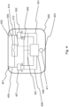
- Figure 4 shows an embodiment of an extension element 600
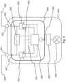
- Figure 5 shows the extension element 600 as integrated within a device 604.
- the device 604 comprises a control unit 203, a light 204, an input port 201 and an output port 202.
- the extension element 600 comprises a first connection point 401, a second connection point 402 and a third connection point 403.
- the connection points 401, 402, 403 are, for example, embodied as connectors arranged on a printed circuit board.
- the first connection point 401 is connected to the input port 201 and the second connection point 402 is connected to the output port 202.
- the third connection point is connected to the control unit 203.
- the extension element 600 further comprises a switch 405, for example a relay.
- the switch 405 is connected to the first and second connection point 401, 402, via connections 409 and 410.
- a direct connection is present between the first and second connection point 401, 402, formed by connections 409, 410 and the switch 405.
- the closed switch 405 together with the communication cables 205, 206, forms part of the common bus of the network.
- the direct connection 409-410 between the first and second connection point 401, 402 is broken.
- the processing unit is thus located in a branch 408 of the common bus 409-410, here to the left of the switch 405.
- connection 501-410 present between the processing unit 406 and the second connection point 402, in which this connection does not comprise the switch 405.
- 501 there is an interface: a first interface 407 and a second interface 502.
- the processing unit 406 is configured to modify the state of the switch 405, as schematically represented by 412.
- extension element 600 may be put in forward status, wherein data traffic will proceed over either the read-write 605 or write-read connection 601.
- the extension element 600 may be put in idle status, wherein no data traffic will happen over both the read-write 605 and write-read connection 601.
- Figure 6 and Figure 7 illustrate the use case of normal operation, i.e. when controlling the devices on the basis of control data sent by a central control element 302.
- the network is controlled in bus mode
- Figure 7 the network is controlled in serial mode.
- FIG. 7 shows the use of a system 703 in bus mode.
- the system 703 comprises a central control element 302, and devices 604 connected to one another via communication cables 701.
- Each device 604 comprises an extension element 600.
- the read-write connection 605 and write-read connection 601 of an extension element 600 was not drawn in the figure.
- each of the switches 405 is in the closed state.
- a direct connection 700 is formed on each extension element 600 between the first and second connection point 401, 402. Together with the communication cables 701, the direct connections 700 form the common bus of the network. Control data sent by the central control element 302 are received simultaneously by each of the devices 604.
- Figure 8 and Figure 9 show the extension element 600 when being put in forward state or idle state respectively.
- the switch 405 is opened, showing that the network is operated in serial mode.
- control data is transmitted to the devices 604, like was shown in Figure 7 , the extension elements 600 of the successive devices 604 are in forward status. However, when no control data is being exchanged, the extension elements 600 will be put in idle status.
- the write-read connection 601 is drawn in the figure. In practice, also a read-write connection 605 is present.
- Figure 8 shows that in forward status, control data is transmitted directly over the write-read connection 601.
- the data When being transmitted over the direct connection 601, the data is forwarded without any delay.
- the forward status is obtained by changing one or more impedances: the relative impedance of the various connections is changed in such a way that the electrical signal tends to flow along the connection 601.
- the processing unit 406 actively follows the data frame being transmitted, as is illustrated with 804 in Figure 8 . There are various possibilities to change the relative impedance of the various connections.
- an impedance in the write-read connection 601 may be changed, by means of a variable resistance placed in the write-read connection 601, or by adjusting an impedance of one of the pins of the driver available in the first or second interface 407, 502.
- an impedance in connection 408 or 501, present between an interface and the processing unit 406 is changed.
- a pin of the processing unit 406 may be put at low or high impedance. Also combined changes of impedances are possible. In any case, the change in impedance(s) is triggered by the processing unit 406, and the obtained relative impedances are such that the desired data path is realised.
- Figure 9 shows that in idle status, no data traffic is possible over the write-read connection 601. Similarly, no data traffic is possible over the read-write connection 605, see 606. In this case, relative impedances are changed in a way that the electrical signal only tends to flow along the path connected with the processing unit 406.
- the processing unit 406 may exchange messages with the central control element 302, see 805 in the figure. For example, a temperature of a device 604 may be requested by the control element 302, thereby using the RDM protocol.
- Every device 604 thus receives its control data at quasi the same moment, thereby allowing for a very accurate synchronised control.
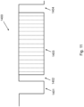
- the procession unit 406 actively tracks the data frame 1400.
- the processing unit 406 knows the standard composition of a data frame 1400, i.e. rules according to used protocol have been programmed in the logic of the processing unit 406. Based on this, the processing unit 406 can detect the end of the data frame 1400. In particular, the processing unit 406 will detect that 512 data slots in the sequence 1402 have passed through, indicating that the data frame 1400 has come to an end. Detecting the end of the data frame 1400 will trigger the processing unit 406 to put the extension element 600 back into idle status.
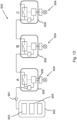
- Figure 13 and Figure 14 illustrate the use case of determining the order of the devices in the network during initial configuration.
- the central control element identifies which devices are connected, and in which order they are located in the network.
- Figure 13 illustrates a first method for determining the order, in a sequential manner
- Figure 14 illustrates a second method, using neighbour determination.
- the network is operated in bus mode, but during initial configuration selected switches 405 are temporarily opened.
- the central control element 902 additionally comprises a configuration module 903. After identification and determination of the order by the topology module 904, the configuration module 903 can, for example, send a message addressed to a specific device 604, in which the start address is given. The entire configuration can proceed automatically in this way.
- Figure 14 illustrates the determination of the order of the connected devices 604 in a second way, based on neighbour determination.
- the system 1005 comprises devices 604 and a central control element 1002 with topology module 1004.
- Each device 604 comprises an extension element 600 according to the second embodiment. Again, not every detail of the extension element 600 is drawn in the figure.
- the processing unit 406 of each extension element 600 is configured to identify a neighbouring device.
- the topology module 1004 is configured to determine, by carrying out a sequence, the order of the devices 604 in a second way, based on neighbour determination. This sequence comprises, for example, the following steps, carried out successively:
- the above second method for determining the order of the connected devices 604, based on neighbour determination, may analogously be applied by manipulating the relative impedances instead of manipulating the switches 405.
- the switch 405 of each of the extension elements 600 stays open for the entire configuration phase. Neighbour determination now takes place by "opening" the read-write and write-read connections, thereby impeding transmission along these lines.
- each device 604 requests the ID of its neighbour to the right, and it transmits its own ID to its neighbour on the left. After “closing" all of the connections again but with switch 405 still open, the topology module 1004 can then request all of the IDs.
- the central control element 1102 comprises a self-healing module 1100 by means of which, on the occurrence of a defect in a communication cable the data traffic can be restored. This takes place, for example, as follows:
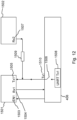
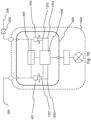
- Figure 16 illustrates an alternative method for monitoring the first or second interface 407, 502, in which anomaly detection is not based on a measured voltage difference, but rather use is made of the read and write port of the interfaces. In this way, the cost for an extra component for measuring voltage can be avoided.
- the figure shows the extension element 600.
- the first interface 407 comprises a read port "R1" and a write port "W1".
- the second interface 502 comprises a read port "R2" and a write port "W2".
- the processing unit 407 is configured to monitor the read and write ports. This takes place, for example, as follows:
Landscapes
- Engineering & Computer Science (AREA)
- Computer Networks & Wireless Communication (AREA)
- Signal Processing (AREA)
- Small-Scale Networks (AREA)
Claims (15)
- Erweiterungselement (600) für eine Vorrichtung (604), wobei die Vorrichtung (604) dazu geeignet ist, über ein erstes (205) und ein zweites (206) Kommunikationskabel mit anderen Vorrichtungen in einem linearen Netzwerk mit Bus-Topologie verbunden zu werden,wobei das Erweiterungselement (600) Folgendes umfasst:- einen ersten (401) und einen zweiten (402) Verbindungspunkt, die zum Verbinden des Erweiterungselements (600) mit dem ersten (205) beziehungsweise dem zweiten Kommunikationskabel (206) geeignet sind;- einen dritten Verbindungspunkt (403), der zum Verbinden des Erweiterungselements (600) mit einer Steuereinheit (203), die in der Vorrichtung (604) umfasst ist, geeignet ist;- einen Schalter (405), der mit dem ersten (401) und dem zweiten Verbindungspunkt (402) verbunden ist;DADURCH GEKENNZEICHNET, DASS:
das Erweiterungselement (600) Folgendes umfasst:- eine Verarbeitungseinheit (406), die mit dem dritten Verbindungspunkt (403) verbunden ist;- eine erste (407) und eine zweite (502) Schnittstelle, die für den Datenaustausch zwischen dem ersten (401) beziehungsweise dem zweiten (402) Verbindungspunkt und der Verarbeitungseinheit (406) ausgelegt sind, wobei die Verarbeitungseinheit (406) mittels der ersten Schnittstelle (407) über eine Verbindung, die den Schalter (405) nicht umfasst, mit dem ersten Verbindungspunkt (401) verbunden ist und die Verarbeitungseinheit (406) mittels der zweiten Schnittstelle (502) über eine Verbindung, die den Schalter (405) nicht umfasst, mit dem zweiten Verbindungspunkt (402) verbunden ist;- eine Lese-/Schreibverbindung (605) zwischen dem Leseport der ersten Schnittstelle (407) und dem Schreibport der zweiten Schnittstelle (502) und eine Schreib-/Leseverbindung (601) zwischen dem Schreibport der ersten Schnittstelle (407) und dem Leseport der zweiten Schnittstelle (502),wobei die Verarbeitungseinheit (406) zu Folgendem konfiguriert ist:- Modifizieren des Zustands des Schalters (405) derart, dass:∘ im geschlossenen Zustand des Schalters (405) eine direkte Verbindung zwischen dem ersten (401) und dem zweiten (402) Verbindungspunkt vorliegt, wobei die direkte Verbindung nicht die erste (407) und die zweite (502) Schnittstelle umfasst,
sodass in einem installierten Zustand des Erweiterungselements (600), wobei das Erweiterungselement (600) durch Verbinden des ersten (401) beziehungsweise des zweiten (402) Verbindungspunkts mit dem ersten (205) beziehungsweise dem zweiten (206) Kommunikationskabel in dem Netzwerk verbunden ist, die direkte Verbindung zwischen dem ersten (401) und dem zweiten (402) Verbindungspunkt einen Teil des gemeinsamen Busses (700, 701) des Netzwerks bildet;∘ im offenen Zustand des Schalters (405) die direkte Verbindung unterbrochen ist;- im offenen Zustand des Schalters (405), Ändern des Status des Erweiterungselements (600) von einem Leerlaufstatus, wobei kein Datenverkehr über die Lese-/Schreib- (605) und die Schreib-/Leseverbindung (601) möglich ist und Daten gezwungen werden, entlang eines Pfads über die Verarbeitungseinheit (406) zu fließen, in einen Weiterleitungsstatus, wobei Datenverkehr über die Lese-/Schreib- (605) oder die Schreib-/Leseverbindung (601) möglich ist und Daten gezwungen werden, entlang eines Pfads über die Lese-/Schreib- (605) oder Schreib-/Lese(601)verbindung zu fließen,wobei das Ändern des Status durch die Verarbeitungseinheit (406) durch Initiieren einer Änderung in einer oder mehreren ausgewählten Impedanzen erfolgt, wobei die ausgewählte Impedanz eine Impedanz in der Lese-/Schreibverbindung (605) oder in der Schreib-/Leseverbindung (601) oder in einer Verbindung zwischen der ersten Schnittstelle (407) und der Verarbeitungseinheit (406) oder in einer Verbindung zwischen der zweiten (502) Schnittstelle und der Verarbeitungseinheit (406) ist, wodurch die relativen Impedanzen in den jeweiligen Verbindungen geändert werden und Daten gezwungen werden, gemäß dem Pfad mit der niedrigsten relativen Impedanz zu fließen. - Erweiterungselement (400, 500, 600) gemäß Anspruch 1,
wobei das Erweiterungselement (600) geeignet ist, in einem Gehäuse (108) der Vorrichtung (604) installiert zu werden, und wobei der erste (401) beziehungsweise der zweite (402) Verbindungspunkt geeignet sind, sich in dem installierten Zustand mit einem Eingangsport (201) beziehungsweise Ausgangsport (202) zu verbinden, der in dem Gehäuse (108) der Vorrichtung (604) umfasst ist. - Erweiterungselement (600) gemäß einem der vorhergehenden Ansprüche, wobei die Verarbeitungseinheit (406) zu Folgendem konfiguriert ist:- Interpretieren von über den ersten Verbindungspunkt (401) empfangenen Steuerdaten und Konfigurationseinstellungen und Übertragen der Steuerdaten und Konfigurationseinstellungen über den dritten Verbindungspunkt (403) an die Steuereinheit (203);- Anfordern einer oder mehrerer Eigenschaften der Vorrichtung über den dritten Verbindungspunkt (403) und Übermitteln der Eigenschaften über den ersten Verbindungspunkt (401).
- Erweiterungselement (600) gemäß einem der vorhergehenden Ansprüche,
wobei das Erweiterungselement (600) dazu ausgelegt ist, die Vorrichtung (604) gemäß einem Protokoll zu steuern, wobei das Protokoll die Zusammensetzung eines Datenframes (1400) definiert, wobei der Datenframe (1400) eine Sequenz von Steuerdaten (1403) umfasst, die für aufeinanderfolgende Vorrichtungen in dem Netzwerk geplant sind, und wobei der Sequenz von Steuerdaten (1403) eine Unterbrechungsdauer (1401) vorangeht, wobei die Unterbrechungsdauer (1401) eine Wartedauer definiert, in der, obwohl der Datenframe (1400) gestartet wurde, keine Steuerdaten an die aufeinanderfolgenden Vorrichtungen in dem Netzwerk gesendet werden. - Erweiterungselement (600) gemäß Anspruch 4,
wobei die Verarbeitungseinheit (406) dazu konfiguriert ist, den Status beim Start des Datenframes (1400) vom Leerlaufstatus in den Weiterleitungsstatus zu ändern und den Status am Ende des Datenframes (1400) vom Weiterleitungsstatus in den Leerlaufstatus zu ändern. - Erweiterungselement gemäß Anspruch 5,
wobei die Verarbeitungseinheit (406) einen Datentracker umfasst, der dazu konfiguriert ist, dem Datenframe (1400) aktiv zu folgen, während er über die Lese-/Schreibverbindung (605) oder die Schreib-/Leseverbindung (601) übermittelt wird, und das Ende des Datenframes (1400) basierend auf der durch das Protokoll definierten Datenframezusammensetzung zu erkennen. - Erweiterungselement (500) gemäß einem der vorhergehenden Ansprüche,wobei die Verarbeitungseinheit (406) dazu konfiguriert ist, eine benachbarte Vorrichtung zu identifizieren,indem sie nacheinander den Schalter (405) öffnet, eine Anfrage über den zweiten Verbindungspunkt (402) an die benachbarte Vorrichtung sendet und eine Antwort empfängt, die eine Kennung der benachbarten Vorrichtung umfasst,oder indem sie im offenen Zustand des Schalters (405) nacheinander das Erweiterungselement (600) in den Leerlaufzustand versetzt, eine Anfrage über den zweiten Verbindungspunkt (402) an die benachbarte Vorrichtung sendet und eine Antwort empfängt, die eine Kennung der benachbarten Vorrichtung umfasst.
- Erweiterungselement (600) gemäß einem der vorhergehenden Ansprüche,
wobei die Verarbeitungseinheit (406) dazu konfiguriert ist, einen Defekt (1104) in dem zweiten (206) oder dem ersten (205) Kommunikationskabel durch Überwachen der zweiten (502) beziehungsweise der ersten (407) Schnittstelle zu erkennen und, bei Erkennen einer Anomalie, Öffnen des Schalters (405) und Senden einer Fehlermeldung über die erste (205) beziehungsweise die zweite (502) Schnittstelle. - Vorrichtung (604), die dazu geeignet ist, über ein erstes (205) und ein zweites (206) Kommunikationskabel mit anderen Vorrichtungen in einem linearen Netzwerk mit Bus-Topologie (303) verbunden zu werden, wobei die Vorrichtung (604) Folgendes umfasst:- eine elektrische (204) und/oder mechanische Komponente;- eine Steuereinheit (203), die zum Steuern der elektrischen (204) oder mechanischen Komponente geeignet ist;- ein Erweiterungselement (600) gemäß einem der vorhergehenden Ansprüche, wobei der dritte Verbindungspunkt (403) des Erweiterungselements (600) mit der Steuereinheit (203) verbunden ist.
- System (303) zum Steuern eines Netzwerks von Vorrichtungen, umfassend:- eine oder mehrere Vorrichtungen (604) gemäß Anspruch 9;- ein zentrales Steuerelement (302);- ein oder mehrere Kommunikationskabel (205, 206), wobei jedes Kommunikationskabel zwei der Vorrichtungen (604) miteinander verbindet oder eine der Vorrichtungen (604) mit dem zentralen Steuerelement (302) verbindet,wobei das zentrale Steuerelement (302) dazu konfiguriert ist, Daten an das Netzwerk zu senden und von diesem zu empfangen.
- System (1005) gemäß Anspruch 10,wobei jede der Vorrichtungen (604) ein Erweiterungselement (600) gemäß Anspruch 7 umfasst,und wobei das zentrale Steuerelement (1002) ein Topologiemodul (1004) umfasst, das dazu konfiguriert ist, die Reihenfolge der Vorrichtungen (604) in dem Netzwerk zu bestimmen, indem nacheinander Folgendes vorgenommen wird:- Übermitteln eines Befehls, sodass das Erweiterungselement (600) jeder der Vorrichtungen (604) eine benachbarte Vorrichtung identifiziert;- Anfordern einer Kennung der Vorrichtung und einer identifizierten benachbarten Vorrichtung von jeder der Vorrichtungen (604).
- System (1105) gemäß Anspruch 10 bis 11,wobei jede der Vorrichtungen (604) ein Erweiterungselement (600) gemäß Anspruch 8 umfasst und das zentrale Steuerelement (1102) und die Vorrichtungen (604) in einem Ring verbunden sind,und wobei das zentrale Steuerelement (1102) ein Selbstheilungsmodul (1100) umfasst, das dazu konfiguriert ist, bei Empfangen der Fehlermeldung von einer der Vorrichtungen (604) das Kommunikationskabel mit dem Defekt (1104) zu identifizieren und den Datenverkehr entsprechend anzupassen.
- Verfahren zur Kommunikation in einem Netzwerk von Vorrichtungen (604), die über ein erstes (205) und ein zweites Kommunikationskabel (206) gegenseitig verbunden sind, wobei das Netzwerk eine lineare Bus-Topologie aufweist, wobei das Verfahren Folgendes umfasst:- Bereitstellen eines Erweiterungselements (600) für jede der Vorrichtungen (604), das Folgendes umfasst:∘ einen ersten (401), einen zweiten (402) und einen dritten (403) Verbindungspunkt,∘ einen Schalter (405), der mit dem ersten (401) und dem zweiten (402) Verbindungspunkt verbunden ist,o eine Verarbeitungseinheit (406), die mit dem dritten Verbindungspunkt (403) verbunden ist,o eine erste (407) und eine zweite (502) Schnittstelle, die für den Datenaustausch zwischen dem ersten (401) beziehungsweise dem zweiten (402) Verbindungspunkt und der Verarbeitungseinheit (406) ausgelegt sind, wobei die Verarbeitungseinheit (406) mittels der ersten Schnittstelle (407) über eine Verbindung, die den Schalter (405) nicht umfasst, mit dem ersten Verbindungspunkt (401) verbunden ist und die Verarbeitungseinheit (406) mittels der zweiten Schnittstelle (502) über eine Verbindung, die den Schalter (405) nicht umfasst, mit dem zweiten Verbindungspunkt (402) verbunden ist;∘ eine Lese-/Schreibverbindung (605) zwischen dem Leseport der ersten Schnittstelle (407) und dem Schreibport der zweiten Schnittstelle (502), und eine Schreib-/Leseverbindung (601) zwischen dem Schreibport der ersten Schnittstelle (407) und dem Leseport der zweiten Schnittstelle (502),- Verbinden des ersten (401) beziehungsweise des zweiten Verbindungspunkts (402) mit dem ersten (205) beziehungsweise dem zweiten (206) Kommunikationskabel;- Verbinden des dritten Verbindungspunkts (403) mit einer Steuereinheit (203), die in jeder der Vorrichtungen (604) umfasst ist;- Schließen des Schalters (405) durch die Verarbeitungseinheit (406), sodass eine direkte Verbindung zwischen dem ersten (401) und dem zweiten (402) Verbindungspunkt vorliegt, die einen Teil des gemeinsamen Busses (700, 701) des Netzwerks bildet, dadurch Steuern des Netzwerks im Busmodus;- Öffnen des Schalters (405) durch die Verarbeitungseinheit (406), sodass die direkte Verbindung unterbrochen wird, dadurch Steuern des Netzwerks im seriellen Modus;- im seriellen Modus, Ändern, durch die Verarbeitungseinheit (406), des Status des Erweiterungselements (600) von einem Leerlaufstatus, wobei kein Datenverkehr über die Lese-/Schreib- (605) und die Schreib-/Leseverbindung (601) möglich ist und Daten gezwungen werden, entlang eines Pfads über die Verarbeitungseinheit (406) zu fließen, in einen Weiterleitungsstatus, wobei Datenverkehr über die Lese-/Schreib- (605) oder die Schreib-/Leseverbindung (601) möglich ist und Daten gezwungen werden, entlang eines Pfads über die Lese-/Schreib- (605) oder Schreib-/Lese(601)verbindung zu fließen,wobei das Ändern des Status durch die Verarbeitungseinheit (406) durch Initiieren einer Änderung in einer oder mehreren ausgewählten Impedanzen erfolgt, wobei die ausgewählte Impedanz eine Impedanz in der Lese-/Schreibverbindung (605) oder in der Schreib-/Leseverbindung (601) oder in einer Verbindung zwischen der ersten Schnittstelle (407) und der Verarbeitungseinheit (406) oder in einer Verbindung zwischen der zweiten (502) Schnittstelle und der Verarbeitungseinheit (406) ist, wodurch die relativen Impedanzen in den jeweiligen Verbindungen geändert werden und Daten gezwungen werden, gemäß dem Pfad mit der niedrigsten relativen Impedanz zu fließen.
- Verfahren gemäß Anspruch 13, wobei das Verfahren ferner Folgendes umfasst:- Bereitstellen eines Erweiterungselements (600) gemäß Anspruch 5;- Steuern des Netzwerks im seriellen Modus;- bei Erkennung eines Starts eines Datenframes (1400) durch das Erweiterungselement (600) aufeinanderfolgender Vorrichtungen (604): Versetzen des Erweiterungselements (600) in den Weiterleitungsstatus;- Übermitteln des Datenframes (1400) über die Lese-/Schreibverbindung (605) oder Schreib-/Leseverbindung (601) aufeinanderfolgender Vorrichtungen (604);- bei Erkennung eines Endes eines Datenframes (1400) durch das Erweiterungselement (600) aufeinanderfolgender Vorrichtungen (604): Versetzen des Erweiterungselements (600) in den Leerlaufzustand.
- Verfahren gemäß Anspruch 14, wobei das Verfahren ferner Folgendes umfasst:Steuern der Vorrichtungen (604) gemäß einem Protokoll, wobei das Protokoll die Zusammensetzung eines Datenframes (1400) definiert, wobei der Datenframe (1400) eine Sequenz von Steuerdaten (1403) umfasst, die für aufeinanderfolgende Vorrichtungen in dem Netzwerk geplant sind, und wobei der Sequenz von Steuerdaten (1403) eine Unterbrechungsdauer (1401) vorangeht, wobei die Unterbrechungsdauer (1401) eine Wartedauer definiert, wobei, obwohl der Datenframe (1400) gestartet wurde, keine Steuerdaten an die aufeinanderfolgenden Vorrichtungen in dem Netzwerk gesendet werden,und wobei die Unterbrechungsdauer (1401) des Datenframes (1400) derart ist, dass die Zeit zum aufeinanderfolgenden Versetzen des Erweiterungselements (600) aufeinanderfolgender Vorrichtungen (604) in den Weiterleitungsstatus kürzer ist als die Unterbrechungsdauer (1401), wodurch ermöglicht wird, dass innerhalb der Zeit der Unterbrechungsdauer (1401) jedes Erweiterungselement (600) der aufeinanderfolgenden Vorrichtungen (604) in den Weiterleitungsstatus versetzt wird.
Applications Claiming Priority (2)
| Application Number | Priority Date | Filing Date | Title |
|---|---|---|---|
| BE20205744A BE1028726B1 (nl) | 2020-10-22 | 2020-10-22 | Uitbreidingselement voor een toestel in een bus netwerk |
| PCT/EP2021/079390 WO2022084526A1 (en) | 2020-10-22 | 2021-10-22 | Extension element for a device in a bus network |
Publications (3)
| Publication Number | Publication Date |
|---|---|
| EP4233279A1 EP4233279A1 (de) | 2023-08-30 |
| EP4233279C0 EP4233279C0 (de) | 2025-04-16 |
| EP4233279B1 true EP4233279B1 (de) | 2025-04-16 |
Family
ID=73835284
Family Applications (1)
| Application Number | Title | Priority Date | Filing Date |
|---|---|---|---|
| EP21798677.7A Active EP4233279B1 (de) | 2020-10-22 | 2021-10-22 | Erweiterungselement für ein gerät in einem bus-netzwerk |
Country Status (5)
| Country | Link |
|---|---|
| US (1) | US20230327909A1 (de) |
| EP (1) | EP4233279B1 (de) |
| CN (1) | CN116325666B (de) |
| BE (1) | BE1028726B1 (de) |
| WO (1) | WO2022084526A1 (de) |
Families Citing this family (1)
| Publication number | Priority date | Publication date | Assignee | Title |
|---|---|---|---|---|
| WO2026012606A1 (de) * | 2024-07-12 | 2026-01-15 | Elmos Semiconductor Se | Verfahren zur übertragung von daten von einer sendeeinheit an eine empfangseinheit |
Family Cites Families (6)
| Publication number | Priority date | Publication date | Assignee | Title |
|---|---|---|---|---|
| US5946315A (en) * | 1995-12-28 | 1999-08-31 | Dynarc Inc. | Method and device for synchronizing dynamic synchronous transfer mode in a ring topology |
| US8310089B2 (en) * | 2010-05-03 | 2012-11-13 | Cisco Technology, Inc. | Power sharing network communications device |
| EP2721783B1 (de) * | 2011-06-15 | 2019-05-01 | Osram Sylvania Inc. | Systeme und verfahren für den nachweis von busnetzwerkfehlern und topologie |
| CN102545178B (zh) * | 2012-03-02 | 2014-10-22 | 哈尔滨理工大学 | Rs485线路状态监视器及其监视方法 |
| EP2866387B1 (de) * | 2013-10-25 | 2016-11-30 | Amrona AG | Bussystem und Verfahren zum Betreiben eines solchen Bussystems |
| DE102016009857A1 (de) * | 2016-08-12 | 2018-02-15 | WAGO Verwaltungsgesellschaft mit beschränkter Haftung | Automatische Initialisierungsroutine in einem Automatisierungs-System |
-
2020
- 2020-10-22 BE BE20205744A patent/BE1028726B1/nl active IP Right Grant
-
2021
- 2021-10-22 WO PCT/EP2021/079390 patent/WO2022084526A1/en not_active Ceased
- 2021-10-22 EP EP21798677.7A patent/EP4233279B1/de active Active
- 2021-10-22 US US18/032,886 patent/US20230327909A1/en active Pending
- 2021-10-22 CN CN202180069586.5A patent/CN116325666B/zh active Active
Also Published As
| Publication number | Publication date |
|---|---|
| CN116325666A (zh) | 2023-06-23 |
| EP4233279C0 (de) | 2025-04-16 |
| EP4233279A1 (de) | 2023-08-30 |
| BE1028726B1 (nl) | 2022-05-23 |
| US20230327909A1 (en) | 2023-10-12 |
| WO2022084526A1 (en) | 2022-04-28 |
| CN116325666B (zh) | 2026-03-31 |
| BE1028726A1 (nl) | 2022-05-16 |
Similar Documents
| Publication | Publication Date | Title |
|---|---|---|
| CN109076681B (zh) | 用于互连照明装置的控制器 | |
| US10779368B2 (en) | Control system for lighting devices | |
| EP2250795B1 (de) | Autoadressierungsvorrichtung auf einer busstruktur mit gemeinsamer kommunikation und steuerung sowie verfahren dafür | |
| CN105684361A (zh) | 总线系统及用于操作此类总线系统的方法 | |
| US20230327909A1 (en) | Extension element for a device in a bus network | |
| US20090196627A1 (en) | Distributed driver and can bus communication protocol | |
| US6026078A (en) | Apparatus and method for providing multiple network port configurations | |
| JP5056516B2 (ja) | 空気調和機用伝送装置 | |
| WO2009053097A1 (en) | Monitoring device and method of monitoring programmable lamps | |
| EP3932018B1 (de) | Einheit zur steuerung der datenkommunikation | |
| WO2017157909A1 (en) | Distributed wireless intercom audio routing over ethernet with synchornization and roaming | |
| JP3913608B2 (ja) | 全ての知的タイプなモジュールが同一の使用者入出力インターフェースを共用できる知的タイプな装置 | |
| JPS5937865Y2 (ja) | 装置電源の遠隔操作装置 | |
| US20240028536A1 (en) | Communication system, master unit and slave unit used for communication system, and communication method | |
| CN119066013A (zh) | 一种总线通信系统及方法 | |
| JP2019175582A (ja) | 照明制御装置、照明制御システムおよび照明制御方法 | |
| CN117167068A (zh) | 基于EtherCAT的新型液压支架控制器 | |
| KR20200134007A (ko) | 무대장치 제어 시스템 및 이의 운용 방법 | |
| JPS61154433A (ja) | 4線配線リモコン方式 |
Legal Events
| Date | Code | Title | Description |
|---|---|---|---|
| STAA | Information on the status of an ep patent application or granted ep patent |
Free format text: STATUS: UNKNOWN |
|
| STAA | Information on the status of an ep patent application or granted ep patent |
Free format text: STATUS: THE INTERNATIONAL PUBLICATION HAS BEEN MADE |
|
| PUAI | Public reference made under article 153(3) epc to a published international application that has entered the european phase |
Free format text: ORIGINAL CODE: 0009012 |
|
| STAA | Information on the status of an ep patent application or granted ep patent |
Free format text: STATUS: REQUEST FOR EXAMINATION WAS MADE |
|
| 17P | Request for examination filed |
Effective date: 20230522 |
|
| AK | Designated contracting states |
Kind code of ref document: A1 Designated state(s): AL AT BE BG CH CY CZ DE DK EE ES FI FR GB GR HR HU IE IS IT LI LT LU LV MC MK MT NL NO PL PT RO RS SE SI SK SM TR |
|
| DAV | Request for validation of the european patent (deleted) | ||
| DAX | Request for extension of the european patent (deleted) | ||
| GRAP | Despatch of communication of intention to grant a patent |
Free format text: ORIGINAL CODE: EPIDOSNIGR1 |
|
| STAA | Information on the status of an ep patent application or granted ep patent |
Free format text: STATUS: GRANT OF PATENT IS INTENDED |
|
| INTG | Intention to grant announced |
Effective date: 20240226 |
|
| GRAS | Grant fee paid |
Free format text: ORIGINAL CODE: EPIDOSNIGR3 |
|
| GRAJ | Information related to disapproval of communication of intention to grant by the applicant or resumption of examination proceedings by the epo deleted |
Free format text: ORIGINAL CODE: EPIDOSDIGR1 |
|
| GRAL | Information related to payment of fee for publishing/printing deleted |
Free format text: ORIGINAL CODE: EPIDOSDIGR3 |
|
| STAA | Information on the status of an ep patent application or granted ep patent |
Free format text: STATUS: REQUEST FOR EXAMINATION WAS MADE |
|
| INTC | Intention to grant announced (deleted) | ||
| GRAP | Despatch of communication of intention to grant a patent |
Free format text: ORIGINAL CODE: EPIDOSNIGR1 |
|
| STAA | Information on the status of an ep patent application or granted ep patent |
Free format text: STATUS: GRANT OF PATENT IS INTENDED |
|
| INTG | Intention to grant announced |
Effective date: 20241114 |
|
| GRAA | (expected) grant |
Free format text: ORIGINAL CODE: 0009210 |
|
| STAA | Information on the status of an ep patent application or granted ep patent |
Free format text: STATUS: THE PATENT HAS BEEN GRANTED |
|
| AK | Designated contracting states |
Kind code of ref document: B1 Designated state(s): AL AT BE BG CH CY CZ DE DK EE ES FI FR GB GR HR HU IE IS IT LI LT LU LV MC MK MT NL NO PL PT RO RS SE SI SK SM TR |
|
| REG | Reference to a national code |
Ref country code: GB Ref legal event code: FG4D |
|
| REG | Reference to a national code |
Ref country code: CH Ref legal event code: EP Ref country code: DE Ref legal event code: R096 Ref document number: 602021029313 Country of ref document: DE |
|
| REG | Reference to a national code |
Ref country code: IE Ref legal event code: FG4D |
|
| U01 | Request for unitary effect filed |
Effective date: 20250505 |
|
| U07 | Unitary effect registered |
Designated state(s): AT BE BG DE DK EE FI FR IT LT LU LV MT NL PT RO SE SI Effective date: 20250512 |
|
| PG25 | Lapsed in a contracting state [announced via postgrant information from national office to epo] |
Ref country code: ES Free format text: LAPSE BECAUSE OF FAILURE TO SUBMIT A TRANSLATION OF THE DESCRIPTION OR TO PAY THE FEE WITHIN THE PRESCRIBED TIME-LIMIT Effective date: 20250416 |
|
| PG25 | Lapsed in a contracting state [announced via postgrant information from national office to epo] |
Ref country code: NO Free format text: LAPSE BECAUSE OF FAILURE TO SUBMIT A TRANSLATION OF THE DESCRIPTION OR TO PAY THE FEE WITHIN THE PRESCRIBED TIME-LIMIT Effective date: 20250716 Ref country code: GR Free format text: LAPSE BECAUSE OF FAILURE TO SUBMIT A TRANSLATION OF THE DESCRIPTION OR TO PAY THE FEE WITHIN THE PRESCRIBED TIME-LIMIT Effective date: 20250717 |
|
| PG25 | Lapsed in a contracting state [announced via postgrant information from national office to epo] |
Ref country code: PL Free format text: LAPSE BECAUSE OF FAILURE TO SUBMIT A TRANSLATION OF THE DESCRIPTION OR TO PAY THE FEE WITHIN THE PRESCRIBED TIME-LIMIT Effective date: 20250416 |
|
| PG25 | Lapsed in a contracting state [announced via postgrant information from national office to epo] |
Ref country code: HR Free format text: LAPSE BECAUSE OF FAILURE TO SUBMIT A TRANSLATION OF THE DESCRIPTION OR TO PAY THE FEE WITHIN THE PRESCRIBED TIME-LIMIT Effective date: 20250416 |
|
| PG25 | Lapsed in a contracting state [announced via postgrant information from national office to epo] |
Ref country code: RS Free format text: LAPSE BECAUSE OF FAILURE TO SUBMIT A TRANSLATION OF THE DESCRIPTION OR TO PAY THE FEE WITHIN THE PRESCRIBED TIME-LIMIT Effective date: 20250716 |
|
| PG25 | Lapsed in a contracting state [announced via postgrant information from national office to epo] |
Ref country code: IS Free format text: LAPSE BECAUSE OF FAILURE TO SUBMIT A TRANSLATION OF THE DESCRIPTION OR TO PAY THE FEE WITHIN THE PRESCRIBED TIME-LIMIT Effective date: 20250816 |
|
| U20 | Renewal fee for the european patent with unitary effect paid |
Year of fee payment: 5 Effective date: 20251031 |
|
| PGFP | Annual fee paid to national office [announced via postgrant information from national office to epo] |
Ref country code: GB Payment date: 20251022 Year of fee payment: 5 |
|
| PG25 | Lapsed in a contracting state [announced via postgrant information from national office to epo] |
Ref country code: SM Free format text: LAPSE BECAUSE OF FAILURE TO SUBMIT A TRANSLATION OF THE DESCRIPTION OR TO PAY THE FEE WITHIN THE PRESCRIBED TIME-LIMIT Effective date: 20250416 |
|
| PG25 | Lapsed in a contracting state [announced via postgrant information from national office to epo] |
Ref country code: CZ Free format text: LAPSE BECAUSE OF FAILURE TO SUBMIT A TRANSLATION OF THE DESCRIPTION OR TO PAY THE FEE WITHIN THE PRESCRIBED TIME-LIMIT Effective date: 20250416 |
|
| PG25 | Lapsed in a contracting state [announced via postgrant information from national office to epo] |
Ref country code: SK Free format text: LAPSE BECAUSE OF FAILURE TO SUBMIT A TRANSLATION OF THE DESCRIPTION OR TO PAY THE FEE WITHIN THE PRESCRIBED TIME-LIMIT Effective date: 20250416 |
|
| PLBE | No opposition filed within time limit |
Free format text: ORIGINAL CODE: 0009261 |
|
| STAA | Information on the status of an ep patent application or granted ep patent |
Free format text: STATUS: NO OPPOSITION FILED WITHIN TIME LIMIT |
|
| REG | Reference to a national code |
Ref country code: CH Ref legal event code: L10 Free format text: ST27 STATUS EVENT CODE: U-0-0-L10-L00 (AS PROVIDED BY THE NATIONAL OFFICE) Effective date: 20260225 |
|
| 26N | No opposition filed |
Effective date: 20260119 |