EP4232786B1 - Mehrachsige kraftdrehmomentmessvorrichtung und haltestruktur zur verwendung damit - Google Patents
Mehrachsige kraftdrehmomentmessvorrichtung und haltestruktur zur verwendung damit Download PDFInfo
- Publication number
- EP4232786B1 EP4232786B1 EP21799039.9A EP21799039A EP4232786B1 EP 4232786 B1 EP4232786 B1 EP 4232786B1 EP 21799039 A EP21799039 A EP 21799039A EP 4232786 B1 EP4232786 B1 EP 4232786B1
- Authority
- EP
- European Patent Office
- Prior art keywords
- connector
- clamping element
- test object
- holding structure
- stiffness matrix
- Prior art date
- Legal status (The legal status is an assumption and is not a legal conclusion. Google has not performed a legal analysis and makes no representation as to the accuracy of the status listed.)
- Active
Links
Images







Classifications
-
- G—PHYSICS
- G01—MEASURING; TESTING
- G01L—MEASURING FORCE, STRESS, TORQUE, WORK, MECHANICAL POWER, MECHANICAL EFFICIENCY, OR FLUID PRESSURE
- G01L3/00—Measuring torque, work, mechanical power, or mechanical efficiency, in general
- G01L3/02—Rotary-transmission dynamometers
- G01L3/04—Rotary-transmission dynamometers wherein the torque-transmitting element comprises a torsionally-flexible shaft
- G01L3/10—Rotary-transmission dynamometers wherein the torque-transmitting element comprises a torsionally-flexible shaft involving electric or magnetic means for indicating
- G01L3/108—Rotary-transmission dynamometers wherein the torque-transmitting element comprises a torsionally-flexible shaft involving electric or magnetic means for indicating involving resistance strain gauges
-
- G—PHYSICS
- G01—MEASURING; TESTING
- G01L—MEASURING FORCE, STRESS, TORQUE, WORK, MECHANICAL POWER, MECHANICAL EFFICIENCY, OR FLUID PRESSURE
- G01L3/00—Measuring torque, work, mechanical power, or mechanical efficiency, in general
- G01L3/02—Rotary-transmission dynamometers
- G01L3/14—Rotary-transmission dynamometers wherein the torque-transmitting element is other than a torsionally-flexible shaft
- G01L3/1407—Rotary-transmission dynamometers wherein the torque-transmitting element is other than a torsionally-flexible shaft involving springs
- G01L3/1428—Rotary-transmission dynamometers wherein the torque-transmitting element is other than a torsionally-flexible shaft involving springs using electrical transducers
- G01L3/1457—Rotary-transmission dynamometers wherein the torque-transmitting element is other than a torsionally-flexible shaft involving springs using electrical transducers involving resistance strain gauges
Definitions
- the present invention is generally related to a holding structure for a multi-axis force-torque sensing device, and to a multi-axis force-torque sensing device comprising such a holding structure for measuring at least one force-torque component, optionally also power, on a test object clamped by the holding structure.
- Force-torque sensors are used in robotics, vehicles, machinery, and other applications where the force-torque acting on an element such as a part of a machine is desired to be quantified.
- Some existing force-torque sensors require direct installation in the transmission path of the force-torque acting on the part, requiring modification of the part and causing its dynamic behaviour to be altered, which may be undesirable. Such force-torque sensors also tend to require dismantling of the machine for installation. Hence, there is an ongoing need to provide an improved, scalable compact holding structure, which is easy to manufacture and measures accurately force-torque components in plural directions.
- the present invention aims to overcome the above stated shortcomings and to provide a multi-axis force-torque sensing device which is compact, requires a minimum of manufacturing steps as compared to existing force-torque sensing devices, and is able to provide accurate measurements of force-torque components in plural directions with a minimum of, or even without, any modifications to a test object itself but only including a releasable add-on force-torque sensing device that has limited influence on the dynamics of the test object.
- the present invention provides for this purpose a holding structure for a multi-axis force-torque sensing device for measuring at least one force-torque component on a test object in accordance with claim 1.
- the holding structure it is an advantage of the holding structure to have a compact device size due to the limited number of technical features and their small dimensions. Moreover, the holding structure does not substantially affect the dynamic behaviour of the test object. It is an advantage of the invention that the coupling projections allow having limited but rigid coupling with the test object, minimizing the effect of surface irregularities on the clamping and measurements. The relation between the stiffnesses also excludes the need to measure precisely the coupling stiffness in order to calculate a force or torque component.
- the first and second clamping elements each comprise a first portion and a second portion releasably connectable to the corresponding first portion.
- the first portion of the first clamping element, the first portion of the second clamping element and the first connector defining a first monolithic structure. It is a further advantage of a holding structure according to embodiments of the invention that the monolithic or one-piece structure ensures a smooth predictable dynamic behaviour of the structure when a force-torque is applied. It also decreases the chance for misalignments, stress concentrations and the need for larger components.
- the coupling between the first end of the first connector and the first inner facing surface of the first clamping element is a glued, welded, or adhesively bonded connection. It is an advantage of embodiments of the present invention that the gluing, welding or adhesively bonding of at least one portion of the first connector to at least one portion of the first inner facing surface of the first clamping element does not require any further modifications to these elements to receive additional fastening means, like bolts or screws, to fasten these elements together. Moreover, the holding structure ensures a smooth predictable dynamic behaviour of the structure when a force-torque is applied. It also decreases the chance for misalignments, stress concentrations and the need for larger components.
- the first connector further comprises a second substantially planar portion at the opposite side of the first substantially planar portion, wherein the distance between the planar portions defines a first connector thickness t 1 , and wherein the ratio between the first width w 1 of the first connector and the first connector thickness t 1 is substantially equal to or larger than 5.
- the first connector of the holding structure has a relatively small stiffness in comparison with the other structural features, excluding the need to know or to measure precisely the coupling stiffness in order to calculate a force-torque component.
- having a substantial planar portion or portions on both opposite sides of the connector provides the advantage of placing gauge measurement means for an accurate measurement of at least one six degree-of-freedom force-torque component.
- the holding structure further comprising a second connector having a first end coupled to the first inner facing surface of the first clamping element and a second end coupled to the second inner facing surface of the second clamping element, wherein the second connector is circumferentially spaced apart from the first connector, wherein the second connector further comprises a third substantially planar portion having a second width w 2 located in a second plane for receiving strain measuring means, wherein the second connector has a second connector six degree-of-freedom stiffness matrix,
- the contact engageable portion of at least one of the plurality of first and second coupling projections comprises a spacer or structural element adapted for, when in use, reducing a size discrepancy between the coupling projection and the test object. It is an advantage of embodiments of the present invention that the holding structure comprises these specific coupling projections to ensure a predetermined sufficient stiffness.
- the first substantially planar portion of the first connector is radially extending from a central axis over a distance substantially equal to the first width w 1 , wherein the central axis is defined by the centre of the first aperture and the centre of the second aperture.
- a selection of the first and second coupling projections comprises a neck portion having stress relief grooves. It is an advantage of embodiments of the present invention that the coupling projections comprises stress relief grooves which heavily reduces the contact peaks near the sides allowing for a larger pretension of the test object.
- the angular separation between the first connector and the second connector is at least 30 degrees, in particular substantially equal to 45 degrees, and more in particular substantially equal to 90 degrees. It is an advantage of embodiments of the present invention that the connectors are separated from each other allowing a better measurement of bending moments in both directions.
- the second connector further comprises a fourth substantially planar portion at the opposite side of the third substantially planar portion, wherein the distance between the planar portions defines a second connector thickness t 2 , and wherein the ratio between the second width w 2 of the second connector and the second connector thickness t 2 is substantially equal to or larger than 5.
- the first connector of the holding structure has a relatively small stiffness in comparison with the other structural features, excluding the need to know/measure precisely the coupling stiffness in order to calculate a force or torque component.
- having a substantial planar portion or portions on both opposite sides of the connector provides the advantage of placing gauge measurement means for an accurate measurement of at least one six degree-of-freedom force-torque component.
- a multi-axis force-torque sensing device for measuring at least one force-torque component on a test object, comprising a holding structure according to any of the previous embodiments for holding the test object, further comprising at least one strain measuring means disposed on at least one connector, wherein the strain measuring means is selected from the group consisting of a semiconductor strain sensor, a piezoelectric strain sensor, a resistance-based strain sensor or a surface acoustic wave based strain sensor.
- the multi-axis force-torque sensing device further comprises at least one accelerometer.
- the step of securing the holding structure of the multi-axis force-torque sensing device to the test object comprises a step of mechanically coupling of the holding structure to the test object such that the first clamping element has a first clamping element coupling six degree-of-freedom stiffness matrix with respect to the test object, and such that the second clamping element has a second clamping element coupling six degree-of-freedom stiffness matrix with respect to the test object, wherein each diagonal element of the first connector six degree-of-freedom stiffness matrix is less than each corresponding diagonal element of the first clamping element six degree-of-freedom stiffness matrix with respect to the first connector, and wherein each diagonal element of the first connector six degree-of-freedom stiffness matrix is less than each corresponding diagonal element of the second clamping element six degree-of-freedom stiffness matrix with respect to the first connector.
- a device comprising means A and B should not be limited to devices consisting only of components A and B. It means that with respect to the present invention, the only relevant components of the device are A and B.
- the terms first, second, third and the like in the description and in the claims are used for distinguishing between similar elements and not necessarily for describing a sequential or chronological order. It is to be understood that the terms so used are interchangeable under appropriate circumstances and that the embodiments of the invention described herein are capable of operation in other sequences than described or illustrated herein.
- the terms top, bottom, over, under and the like in the description and the claims are used for descriptive purposes and not necessarily for describing relative positions.
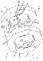
- a holding structure 1 for a multi-axis force-torque sensing device according to embodiments of the present invention is depicted.
- the holding structure comprises a first clamping element 2 and a second clamping element 3, wherein the second clamping element is spaced apart from the first clamping element in a first direction, also referred to as an X-direction.
- the first clamping element 2 has a first inner circumferential surface 2a extending in the first direction (X-direction) and defining a first aperture 2b for receiving a first portion of a test object 4 (not shown in Fig.1 ).
- the first inner circumferential surface 2a comprises a plurality of first coupling projections P1 circumferentially distributed around the first aperture 2b.
- the first coupling projections P1 are circumferentially spaced apart from each other by a plurality of first recesses R1.
- the first coupling projections P1 each comprise a contact-engageable portion, facing radially inward the first aperture 2b, and adapted to mechanically engage or couple with a first portion of an outer surface of the test object 4.
- these contact-engageable portions when in use, mechanically engage with the curvature of the first portion of the outer surface of the test object 4 to ensure larger contact surfaces and reduced stress peaks.
- the contact-engageable portions have a curved surface to receive at least a portion of the outer surface of the test object 4.
- the contact-engageable portion may have an angular width, measured along the circumference of the first aperture 2b, of 45 ⁇ 10 degrees, without being limited thereto.
- the first recesses R1 are circumferentially spaced apart by the first projections P1 and are configured not to engage or mechanically couple with the test object 4.
- the first recesses R1 have a substantially flat surface adapted to receive sensing means, without being limited thereto, temperature sensing and/or clamping force measuring means.
- suitable couplers or coupling means particular embodiments of the invention may include a mechanical coupling, without being limited thereto, meaning any appropriate coupling means that allows forces to be selectively transmitted between the test object 4 and the first clamping element 2.
- the first inner circumferential surface 2a may further comprise concave-shaped recesses disposed in between the contact-engaged end portions of the first coupling projection P1 and the first recess R1, configured to have the advantage of reducing contact peaks and overall stress near the contact-engaged end portions of the first coupling projections P1.
- the first clamping element 2 further comprises a first outer circumferential surface 2c opposed to and spaced radially outward from the first inner circumferential surface 2a.
- the first outer circumferential surface 2c extends in the first direction (X-direction), defining the thickness of the first clamping element 2.
- the first clamping element 2 may have a minimal first thickness of six (6) millimeters (mm), preferably eight (8) millimeters (mm).
- the second clamping element 3 has a second inner circumferential surface 3a extending in the first direction (X-direction) and defining a second aperture 3b for receiving a second portion of the test object 4.
- the second inner circumferential surface 3b comprises a plurality of second coupling projections P2 distributed around the second aperture 3b.
- the second coupling projections P2 are circumferentially spaced apart from each other by a plurality of second recesses R2.
- the second coupling projections P2 each comprise a contact-engageable portion adapted to mechanically engage or couple with a second portion of an outer surface of the test object 4.
- these contact-engageable portions when in use, mechanically engage with the curvature of the second portion of the outer surface of the test object 4 to ensure larger contact surfaces and reduced stress peaks.
- the contact-engageable portions may have a curved surface to receive at least a portion of the outer surface of the test object 4.
- the contact-engageable portion may have an angular width, measured along the circumference of the second aperture 2b, of 45 ⁇ 10 degrees, without being limited thereto.
- the second recesses R2 are circumferentially spaced apart by the second projections P2 and are configured not to engage or mechanically couple with the test object 4.
- the second recesses R2 have a substantially flat surface adapted to receive sensing means, without being limited thereto, temperature sensing and/or clamping force measuring means.
- suitable couplers or coupling means particular embodiments of the invention may include a mechanical coupling, without being limited thereto, meaning any appropriate coupling means that allows forces to be selectively transmitted between the test object 4 and the second clamping element 3.
- the second inner circumferential surface 3a may further comprise concave-shaped recesses disposed in between the contact-engaged end portions of the second coupling projection P2 and the second recess R2, configured to have the advantage of reducing contact peaks and overall stress near the contact-engaged end portions of the second coupling projections P2.
- the second clamping element 3 further comprises a second outer circumferential surface 3c opposed to and radially spaced apart from the first inner circumferential surface.
- the second outer circumferential surface 3c extends in the first direction (X-direction), defining the thickness of the second clamping element 3.
- the second clamping element 3 may have a minimal second thickness of six (6) millimetres (mm), preferably eight (8) millimetres (mm).
- the holding structure further comprises a first connector 5 having a first end 5a (not visible in Fig.1 ) coupled to a first inner facing surface 2d (not visible in Fig.1 ) of the first clamping element 2 and a second end 5b coupled to a second inner facing surface 3d of the second clamping element 3.
- the first inner facing surface 2d extends between first inner circumferential surface 2a and the first outer circumferential surface 2d and faces the second clamping element 3.
- the second inner facing surface 3d extends between second inner circumferential surface 3a and the second outer circumferential surface 3b and faces the first clamping element 2.
- the first outer facing surface 2e Opposed to and separated in the first direction (X-direction) from the first inner facing surface 2d of the first clamping element is the first outer facing surface 2e.
- the first outer facing surface 2e extends between the first inner circumferential surface 2a and the first outer circumferential surface 2c of the first clamping element 2.
- the width of the first clamping element 2, also referred to as the thickness of the first clamping element 2 may be defined as the distance, measured along the first direction (X-direction), between the first outer facing surface 2e and the first inner facing surface 2d.
- the width of the first clamping element, or thickness of the first clamping element is predetermined to ensure sufficiently stiff connection between the first clamping element 2 and the test object 4 when the multi-axis force-torque sensing device, according to embodiments of the invention, is in use.
- the first connector 5 of the holding structure 1 further comprises a first substantially flat portion 5c for receiving strain measuring means (not shown), wherein the first portion is located in a first plane.
- this first plane may extend radially outward from a central axis 7 over a distance substantially equal to a first width w 1 (defined later), wherein the central axis 7 is extending in the first direction (X-direction) and defined by the centre of the first aperture 2b and the centre of the second aperture 3b.
- the central axis 7 may correspond with, when the invention is in use, the longitudinal axis of the test object 4.
- This specific configuration of the first substantially flat portion 5c has the advantage, when a strain measurement means is disposed thereon, of an accurate and efficient measurement of six degree-of-freedom (also referred to as "DOF") force-torque components in comparison with strain measurement means disposed on non-flat, curved portions.
- DOF degree-of-freedom
- the first connector 5 is configured to receive at least one strain measurement means, for example a strain gauge (not shown).
- the strain gauge may comprise of several independent grids to complete a number of Wheatstone bridge configurations optimize the sensor output, when in use. The number of bridge configurations being equal or larger than the number of to be estimated components.
- the first connector 5 comprises a first 5c and a third 5d (not shown in Fig.1 ) substantially flat portion on opposite sides of the connector 5.
- the first connector 5 of the holding structure 1 may have several strain gauges mounted, for example, without being limited thereto, 4 independent grids, connected in a conventional Wheatstone bridge to form a first sensing circuit.
- This first sensing circuit when in use, provides a first output signal responsive to a first force exerted between a test object 4 and the first clamping element 2 under a given load applied at a central point A of the first aperture 2 and a central point B of the second aperture 3.
- a multi-axis force-torque sensing device is capable of measuring forces in any direction and torques about any axis provided that the sensitivity of the force in that direction with respect to the strain output is known.
- strain measurement means for example strain gauges
- linear forces in one, two, or three perpendicular directions and/or torques about one, two, or three perpendicular directions can be determined.
- Embodiments of the present invention can thus provide a holding structure for a multi-axis, six DOF force-torque sensing device and a multi-axis, six DOF force-torque sensing device comprising such a holding structure.
- a holding structure 1 wherein the holding structure is mechanically coupled or engaged with a test object 4.
- a first portion of the outer surface of the test object 4 is in mechanical contact with a plurality of first projections P1 disposed around the first aperture 2b of the first clamping element 2, and a second portion of the outer surface of the test object 4 is in mechanical contact with a plurality of second projections P2 disposed around the second aperture 3b of the second clamping element 3, in order to clamp the test object 4 in the holding structure 1 and to minimize or prevent a rotational and/or a linear adjustment of the holding structure 1 along a longitudinal axis (X-direction) of the test component 4.
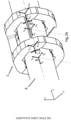
- Fig.2b wherein the holding structure 1 of Fig.2a is in connection with a test object 4, the following points and axes can be defined :
- the stiffness of the test object 4 is defined by the relationship between a unit force applied at point A and the resulting relative displacement between points A and B.
- the stiffness matrix can be numerically or experimentally obtained by applying six independent loading conditions F 1 to F 6 according to equation 1: F x , 1 F x , 2 F x , 3 F x , 4 F x , 5 F x , 6 F y , 1 F y , 2 F y , 3 F y , 4 F y , 5 F y , 6 F z , 1 F z , 2 F z , 3 F z , 4 F z , 5 F z , 6 F xy , 1 F xy , 2 F xy , 3 F xy , 4 F xy , 5 F xy , 6 F xy , 1 F xy , 2 F xy , 3 F xy , 4 F xy , 5 F xy
- the force components in the y and z directions for load F n are similarly represented by F y,n and F z,n respectively.
- the torque component about the z direction is represented by F xy,n and similarly F yz,n represents the torque about the x direction and F zx,n the torque about the y direction.
- the relative displacements between points A and B are represented by the indexed D values, thus for example D y,4 is the displacement in the y direction subjected to a load F 4 and D zx,3 is angle about the y axis subjected to a load F 3 .
- the stiffness matrix of the test object is represented by [ k ] T .
- the stiffness matrix [ k ] T according to each direction can be determined by multiplying the force matrix [F] with the inverse of the displacement matrix [D].
- the stiffness matrix of a system of the sensing device 1 coupled to the test object 4, as depicted in Fig.2a and Fig.2b , may be referred to as [K] M+T , wherein the subscript "M+T" represents the combined system of the multi-axis force-torque sensing device, referred to as "M", and the test object 4, referred to as "T".
- M multi-axis force-torque sensing device
- T the stiffness matrix of the holding structure 1 of the multi-axis force-torque sensing device.
- the stiffness matrix of the system can again be determined by multiplying the respective force matrix with the inverse of the displacement matrix having subscript "AB, M+T".
- [K] M+T may be defined by the relationship between a unit force applied at point A and the resulting relative displacement between points A and B expressed in function of a load.
- F the matrix of forces as in the above equations
- V is a matrix of the voltages measured by the strain sensor for the corresponding applied force
- ⁇ is a calibration matrix which relates measured voltages to applied forces.
- the force acting on the test object 4 is measured by measuring the change in strain on at least one surface of at least one connector.
- At least one strain sensor is required for each force component which is desired to be determined.
- the minimum configuration of the sensing device suitable for measuring a force in one direction, is a single connector and a single strain sensor disposed on the connector between the first and second ends of the connector.
- one or more strain sensors are used which are each configured to measure strain in more than one direction, which can help to make the voltage output substantially insensitive to other loading conditions besides the component of choice.
- the matrix [ ⁇ ] N.M preferably has a substantially small condition number to provide for good invertibility.
- a coupling stiffness diagram is depicted for embodiments of the holding structure, or the multi-axis force-torque sensing device comprising the holding structure according to the invention, wherein the holding structure comprises a single connector 5.
- the overall stiffness of the testing device consisting of one transmission path can be represented as a series of three connected springs.
- the first clamping element stiffness matrix [ k] C1 and the second clamping element stiffness matrix [ k] C2 are in series with the connector stiffness matrix [ k] conn , contributing to the stiffness matrix of the multi-axis force-torque sensing device [ k ] M .
- the first and second clamping element stiffness matrices [ k] C1 , [ k] C2 and the connector stiffness [ k] conn are in parallel with the test component stiffness [ k] T .
- the first connector 5 has a rectangular cross-section.
- the first connector 5 may have various shapes e.g., without being limited thereto, oval, squared, rectangular, T-shaped, I-shaped, etc.
- the first connector 5 may have a cross section which changes in the first direction (X-direction) between the first end 5a and the second end 5b.
- the first connector 5 may have a square cross-section at the first 5a and second 5b end, where the cross section tapers in one direction to a rectangular cross section between the first 5a and second 5b end.
- the first connector may take the form of a flexural hinge.
- the first connector 5 is configured to receive at least one strain measurement means, for example a strain gauge (not shown).
- the strain gauge may comprise six patches with two gauges each to install three full bridges to optimize the sensor output, when in use.
- the first connector 5 is connected or coupled to a portion of the first inner facing surface 2d with a flexural hinge. This smooth transition between the first connector 5 and the first clamping element 2 minimizes stress concentrations.
- the second end 5b of the first connector 5 may also be connected or coupled to the second inner facing surface 3d in a smooth way using a flexural hinge.
- the holding structure 2 may further comprise a second connector 6.
- the second connector 6 having a first end 6a (not visible in Fig.3 ) coupled to the first inner facing surface 2d (not visible in Fig.3 ) of the first clamping element 2 and a second end 6b coupled to a second inner facing surface 3d of the second clamping element 3.
- the second connector 6 may further comprise a second substantially flat portion 6c for receiving strain measuring means (not shown), wherein the second portion is located in a second plane.
- this second plane is extending radially from the central axis 7, wherein the central axis 7 is extending in the first direction (X-direction) and may correspond with, when the invention is in use, the longitudinal axis of the test object 4.
- This specific configuration of the second substantially flat portion 6c has the advantage of an accurate measurement of six DOF forces.
- the first connector 5 and second connector 6 are circumferentially spaced apart from each other at the same or substantially the same radial distance from the central axis 7.
- the circumferential distance between the first connector 5 and the second connector 6 may be defined by an angular separation between the first connector 5 and the second connector 6.
- this angular separation is at least 30 degrees, in particular substantially equal to 45 degrees, and more in particular substantially equal to 90 degrees. It is an advantage of embodiments of the present invention that the connectors are separated from each other allowing a better measurement of bending moments in both directions.
- the second connector 6 is configured to receive at least one strain measurement means, for example a strain gauge (not shown).
- the strain gauge may comprise six patches with two gauges each to install three full bridges to optimize the sensor output, when in use.
- the second connector 6 comprises a second 6c and a fourth 6d (not shown in Fig.1 ) substantially flat portion on opposite sides of the second connector 6.
- the second connector 6 of the holding structure 1 may have several strain gauges mounted, for example, without being limited thereto, six patches with 2 gauges each, connected in a conventional Wheatstone bridge to form a second sensing circuit.
- This second sensing circuit when in use, provides a second output signal responsive to a second force and power transmission path exerted between a test object 4 and the first clamping element 2 under a given equivalent resultant load applied at a central point A of the first aperture 2 and a central point B of the second aperture 3.
- the second connector 6 of the holding structure 1 for a multi-axis force-torque sensing device defines a second connector six DOF stiffness matrix.
- This second connector six DOF stiffness matrix describes the relationship between the displacement of the first end 6a and displacement of the second end 6b of the second connector 6 under a predetermined load applied at the central points A and B assuming a rigid connection between A and the first end 6a and a rigid connection between the second end 6b and B.
- the second connector 6 may have various shapes e.g., without being limited thereto, oval, squared, rectangular, T-shaped, I-shaped, etc.
- the second connector 6 may have a cross section which changes in the first direction (X-direction) between the first end 6a and the second end 6b.
- the second connector 6 may have a square cross-section at the first 6a and second 6b end, where the cross section tapers in one direction to a rectangular cross section between the first 6a and second 6b end.
- the second connector 6 may take the form of a flexural hinge.
- the second connector 6 is connected or coupled to a portion of the first inner facing surface 2d with a flexural hinge. This smooth transition between the second connector 6 and the first clamping element 2 minimizes stress concentrations.
- the second end 6b of the second connector 6 may also be connected or coupled to the second inner facing surface 3d in a smooth way using a flexural hinge.
- Each diagonal element of the first connector six DOF stiffness matrix is less than each corresponding diagonal element of the first clamping element six DOF stiffness matrix with respect to the first connector 5, and each diagonal element of the first connector six DOF stiffness matrix is less than each corresponding diagonal element of the second clamping element six DOF stiffness matrix with respect to the first connector 5.
- reference is made to "less” in this case reference is made to at least one order of magnitude, preferably at least two orders of magnitude.
- the first connector 5 has a connector stiffness which is smaller than the first clamping element stiffness, the second clamping element stiffness, and the test component stiffness. Due to the relative magnitudes of the connector stiffness matrix elements, in particular the diagonal elements, and the corresponding clamping element stiffness matrix elements, a force and/or torque transferred to the multi-axis force-torque sensing device at a coupling projection P1 and a coupling projection P2 (for example, when the sensing device is coupled to a test object at a projection P) can be transferred to the connector 5 without substantial effect on the clamping elements 2, 3. Thus by measuring at least one force component acting on the first connector 5, the at least one force component on a test object 4 can be determined.
- the stiffness matrix of the holding structure K M can be defined according to equation 7: k M ⁇ k conn 1 + k conn 2
- the measurement device six DOF stiffness matrix K M is approximately equal to the sum the six DOF stiffness matrix of the first and second connector. This allows the stiffness of the holding structure 1 to be considered approximately equal to the sum of the first and second connector stiffnesses.
- the clamping element stiffnesses do not need to be known exactly and do not need to be used in any calculation of the force or torque. It is sufficient that the first and second connector stiffness is substantially smaller than the first clamping element stiffness and the second clamping element stiffness.
- coupling of a holding structure 1 according to embodiments of the present invention to a test object 4 does not significantly alter the stiffness properties of the test object 4.
- the use of this holding structure does not affect the system dynamics.
- the test object 4 may be subject to one or more forces, which may be linear and/or rotational, which are desired to be measured.
- the principle that the effective stiffness is negligible as compared to the test object stiffness is generalized to a multidimensional description to include cross coupling effects.
- Such forces have a transmission path R in the test object 4 ( Fig.2a ), comprising points at which the test object 4 experiences the force.
- the holding structure 1 according to embodiments of the present invention provides an additional transmission path S in the sensing device 1, which can be thought of as being parallel to the transmission path R in the sense that the effective stiffness k eff can be considered to be in parallel with the test object stiffness k test .
- the measurement device stiffness may be less than 10%, less than 5%, less than 3%, less than 1% of the test object stiffness.
- a multi-axis force-torque sensing device comprises a holding structure 1 according to embodiments of the present invention, wherein the holding structure 1 may comprise at least one strain measuring means disposed on a first substantially flat portion 5c of the first connector 5. Strain measuring means may also be disposed on a second substantially flat portion 5d of the first connector 5, wherein the second substantially flat portion 5d is on the opposite side of the first substantially flat portion 5c of the first connector 5.
- the multi-axis force-torque sensing device may also comprise a second connector 6 having a third substantially flat portion 6c configured to receive strain measuring means.
- the second connector 6 may also have a fourth substantially flat portion 6d on the opposite side of the third substantially flat portion 6c having strain measuring means disposed thereon.
- the third and fourth substantially planar portion of the second connector may extend radially from a central axis over a distance substantially equal to the second width w 2 , wherein the central axis is defined by the center of the first aperture and the center of the second aperture.
- the at least one strain measuring means may be for example, without being limited thereto, a strain sensor, a semiconductor strain sensor, a piezoelectric strain sensor, or a resistance-based strain sensor, or a surface acoustic wave based strain sensor or a combination thereof.
- the strain measuring means (not shown in the figures) is configured to output a voltage or current according to a local deformation in one or more directions.
- the strain measurement means may comprise a resistance strain gauge having a force sensitivity in one or more different measurement directions.
- a force F in the measurement direction can be determined in dependence upon the measured deformation amount and the total stiffness of the holding structure 1 for the multi-axis force-torque sensing device.
- a first monolithic structure of a holding structure 1 for a multi-axis force-torque sensing device may be defined by a first portion 8 of the first clamping element 2, at least one connector 5, 6, and a first portion 10 of the second clamping element 6.
- the first portion 8 of the first clamping element 2 comprises a first outer end and a second outer end, wherein both outer ends are configured to mechanically couple with a second portion 9 ( Fig.4 ) of the first clamping element 2.
- the first portion 8 and the second portion 9 may be releasably connectable to each other.
- the outer ends of the first portion 8 may have half-open cavities configured, for example having an inner thread, to receive a fastening means, for example a bolt having an outer thread, wherein the inner thread is adapted to engage with the outer thread of the bolt.
- the bolt may be dimensioned to require a certain preload force while taking up minimal space, i.e. maximizing length of the unthreaded portion as this determine the possible preload.
- the threaded portion is selected to be at least eight (8) times the pitch length which has the advantage of ensuring that the bolt is properly attached to the other clamping portion of the clamping element 2,3.
- a monolithic or one-piece structure ensures a smooth predictable dynamic behavior of the holding structure 1 when a force or torque is applied. It is an advantage of the embodiment to decrease the chance for misalignments, stress concentrations and the need for larger components.
- a perspective view of a second portion 9 and a third portion 11 of a first clamping element 2 and second clamping element 3, respectively, is demonstrated.
- These portions 9,11 may be monolithic structures.
- the second portion 9 of the first clamping element 2 may be defined as a portion releasably connectable to the first portion 8 of the first clamping element 2, wherein this first portion 8 is a corresponding first portion to the second portion 9.
- the second portion 9 has a first end portion and a second end portion adapted to mechanically couple with the first portion 8 ( Fig.3 ) of the first clamping element 2.
- At least one end portion of the second portion 9 may have a through opening or cavity to receive an attaching means, for example a bolt, to releasable connect the first portion 8 to the second portion 9.
- a second portion 11 of the second clamping element may comprise similar or the same features for releasable connect or engage with the first portion 10 of the second clamping element 3.
- the second portion 11 of the second clamping element 3 may be defined as a portion releasably connectable to the first portion 10 of the second clamping element 3, wherein this first portion 10 is a corresponding first portion to the second portion 11 of the second clamping element 3.
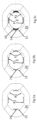
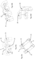
- Fig.5a, Fig.5b and Fig.5c are axial views according to the first direction (X-direction) of the holding structure 1 according to embodiments of the invention, wherein Fig.5a depicts the outer facing surface of the first 2 or second 3 clamping element without the presence of a test object 4, whereas Fig.5b depicts the same structural elements as Fig.5a having a test object 4 clamped.
- the embodiment of the first or second clamping element of the holding structure 1 for a multi-axis force-torque sensing device shown in Fig.5 has an inner circumferential surface comprising four first coupling projections P1 circumferentially spaced apart by a plurality of first recesses R1, wherein two adjacent first coupling projection P1 are separated by a first recess R1.
- a first coupling projection P1 and a first recess R1 may be separated by a first concave shaped recess 15.
- the first concave shaped recesses 15 at both circumferential sides of the first coupling projection P1 may reduce contact peaks and overall stress near the connecting surfaces.
- the neck portion of the first coupling projection P1 may comprise stress relief grooves 14, which heavily reduces the contact peaks near the sides allowing for a larger pretension.
- the same structural and functional features are applicable to the second coupling projection P2 of the second clamping element 3.
- Fig.5c depicts at least the same structural elements as Fig.5b wherein the contact-engaged end portion surface of at least one first coupling projection P1 for mechanically coupling with a first outer surface portion of the test object 4 may comprise a spacer or structural element 16 adapted for reducing a size discrepancy between the first coupling projection P1 and the test object 4 in order to to guarantee a predetermined clamping force.
- FIG.6 a side view of the holding structure 1 according to embodiments of the present invention comprising a test object 4 is shown.
- At least one end portion of the second portion 9,11 may have a through opening or cavity 12,13 to receive an attaching means, for example a bolt, to releasable connect the first portion 8,10 to the second portion 9,11.
- FIG.7 a side view of the holding structure for a multi-axis sensing device according to embodiments of the invention is shown.
- the first clamping element 2 is spaced apart in the first direction (X-direction) from the second clamping element 3, wherein a first connector 5 mechanically connects the first clamping element 2 with the second clamping element 3.
- This particular embodiment of the invention comprises also a second connector 6 mechanically coupling the first clamping element 2 with the second clamping element 3.
- the first clamping element 2 comprises a first portion 8 and a second portion 9 which are separable from each other. Each portion has a generally half-ring shape.
- the portions 8, 9 can be placed around the shaft of test object 4 and then coupled to each other using fastening means like, without being limited thereto, screws (not shown).
- the screws may be received in a holes or cavities 18 in the portions 8, 9.
- the second clamping element 9 may also comprises a first portion 10 and a second portion 11, releasable connectable to each other.
- the portions 10, 11 can be placed around the shaft of test object 4 and then coupled to each other using fastening means like, without being limited thereto, screws (not shown).
- the screws may be received in a holes or cavities 19 in the portions 10, 11.
- This separable configuration of the portions 8, 9, 10, 11 allows the holding structure 1 for a multi-axis force-torque sensing device to be easily coupled to and uncoupled from a test object without requiring the test object to be removed from the system. This also allows easy adjustment of the position of the holding structure at the circumference of the test object.
- the first connector 5 extends between the first clamping element 2 and the second clamping element 6, having a first end 5a coupled to a first inner facing surface of the first clamping element 2 and a second end 5b coupled to a second inner facing surface of the second clamping element 6.
- the length I 1 of the first connector 5 is defined as the distance between the first end 5a and second end 5b.
- the first connector 5 has a rectangular cross-section substantially extending over its length I 1 defining a first and an opposed second substantially flat portion, both having a length I 1 and a first width w1.
- first and an opposed second substantially flat portion both having a length I 1 and a first width w1.
- substantially flat segments of the first connector 5. These flat portions, or segments, are adapted for receiving at least one strain measuring means.
- the thickness t 1 of the first connector 5 (not visible in Fig.7 ) is defined by the distance between the first substantially flat portion and the second substantially flat portion.
- the thickness t 2 of the second connector 5 is illustrated in Fig.7 and is defined in a similar way, i.e. the distance between the first and second substantially flat portions, or segments, of the second connector 6.
- the ration between the first width w1 and first thickness t1 of the first connector 5 is larger or equal to 5. In preferred embodiments of the present invention comprising, the ration between the second width I 2 and second thickness t 2 of the second connector 5 is larger or equal to 5.
- In-situ measurement of force and/or torque on a test object may proceed as follows.
- the multi-axis force-torque sensing device comprising a holding structure according to embodiments of the invention is clamped to the test object, which may be comprised in an engine or other machinery.
- Strain measurements are sent from the sensor(s) to a processing device (not shown) such as a computer or embedded processing unit comprising a memory unit, for example by a wired or wireless connection between the sensors and the processing device.
- the strain measurements may be continuously provided to the processing device or may be provided "on-demand", such as in response to a signal from the processing device.
- the strain measurements are received by the processing device, which stores the calibration matrix in the memory unit, for example as determined during a calibration process as described herein.
- the processing device calculates the forces and torques on the sensing device in dependence upon the received strain values and using the calibration matrix.
- the processing device may provide the forces and torques as output, for example to a control system configured to control a system comprising the test object and/or as a visual and/or audio output.
- a strain sensor (not shown) is disposed on the first connector 5 between the first 5a and second 5b ends, on one of the substantially flat or planar faces of the connector.
- the force-torque sensing device comprising one strain sensor, is capable of measuring a force component in at least one direction.
- a single strain sensor may be capable of measuring strain in more than one direction.
- a multi-axis force-torque sensing device may comprise more than one connector.
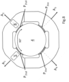
- FIG.8 due to the angular distribution and appropriate choice of orientation of each connector 5,6, and first coupling projections P1 force components in three perpendicular directions can be measured.
- An example orientation of connectors is shown in Figure 5 , where each arrow A 1 , A 2 , A 3 , A 4 denotes the direction of the normal force responsible for the clamping of the clamping element to the test object when coupled.
- First P1 and second P2 coupling projections having a neck portion adjacent to the end points of a connector comprise contact-engaged end portions adapted to maximize the mechanically coupling or contact with a portion of the outer surface of the test object 4.
- each clamping element 2,3 may comprise a predetermined number of full surface contact coupling projections P1 full wherein this predetermined number is at least equal to the number of connectors between the clamping elements of the holding structure.
- two or more connectors 5,6 can be used. Any circumferential distribution of connectors can be used, for example the angular separation of adjacent connectors is not limited to 90°. Preferably, the angular separation between two adjacent connectors is at least 45°. If two connectors are used, then preferably the primary axes of the strain sensors disposed on the connectors are substantially perpendicular to each other.
- each connector has the stiffness matrix properties as described hereinbefore with respect to the first connector 5. That is, each connector 6 has a six DOF stiffness matrix, and for each stiffness matrix individually, each diagonal stiffness matrix element is less than each corresponding element of the six DOF stiffness matrices of the first and the second clamping elements with respect to the connector in question.
- both the test object and the sensing device can experience inertial forces which scale with the velocity, acceleration and inertial properties of the test object.
- inertial forces can impact the statically determined force measurements as described hereinbefore.
- the acceleration of the respective bodies can be estimated.
- the multi-axis force-torque sensing device comprises one additional strain gauge, and/or one additional accelerometer and/or inertial measurement unit for each to be identified acceleration component to account for the inertial contribution.
- the additional strain gauge, accelerometer, and/or inertial measurement unit is preferably attached to the first or the second clamping element or integrated into a printed circuit board.
- these additional measurement means are disposed on the substantially flat or planar surfaces of the first and/or second recesses disposed in between adjacent coupling projections.
- the multi-axis force-torque sensing device optionally comprises a first accelerometer disposed on the first clamping element 2.
- the sensing device optionally comprises a second accelerometer disposed on the second clamping element 3.
- the first and/or second accelerometers are configured to measure an acceleration in one or more perpendicular directions.
- a sensing device according to embodiments of the present invention comprising one or more accelerometers 7, 8 is capable of estimating the velocity and by extension the power in one or more perpendicular directions.
- the velocity can be calculated through integration to determine the power in a particular direction.
- the rotational velocity can be derived from the radial acceleration based on the kinematic description.
- the multi-axis force-torque sensing device can therefore measure six DOF components for both force and power.
- the multi-axis force-torque sensing device optionally comprises one or more temperature sensors.
- the one or more temperature sensors may be used to correct measurements of the strain sensors in the presence of temperature variations.
- a first temperature sensor may be disposed on the first clamping element and a second temperature sensor may be disposed on the second clamping element.
- a temperature value at a sensor between the first clamping element and the second clamping element may be determined based on measurements from the first temperature sensor and the second temperature sensor, for example by interpolation.
- Temperature correction can be advantageous for example when a resistance-based strain sensor is used, as the resistance of wires comprised in the strain sensor can be influenced by a change in temperature.
- FIG.9a, 9b, 9c, 9d and 9e different perspective views of second portions 9 or third portions 11 of respectively a first 2 or second 3 clamping element according to specific embodiments of the present invention are demonstrated.
- These portions 9,11 may be monolithic structures.
- the second portion 9 of the first clamping element 2 may be defined as a portion releasably connectable to the first portion 8 of the first clamping element 2, wherein this first portion 8 is a corresponding first portion to the second portion 9.
- the second portion 9 has a first end portion and a second end portion adapted to mechanically couple with the first portion 8 ( Fig.3 ) of the first clamping element 2. At least one end portion of the second portion 9 may have a through opening or cavity to receive an attaching means, for example a bolt, to releasable connect the first portion 8 to the second portion 9.
- an attaching means for example a bolt
- FIG.9a, 9b, 9c, 9d and 9e different perspective views of second portions 9 or third portions 11 of respectively a first 2 or second 3 clamping element according to specific embodiments of the present invention are demonstrated.
- These portions 9,11 may be monolithic structures. For clarity purposes, only the second portion 9 of the first clamping element 2 has been shown in Fig.9a-9e and described in the following.
- the second portion 9 of the first clamping element 2 may be defined as a portion releasable connectable to the first portion 8 of the first clamping element 2, wherein this first portion 8 is a corresponding first portion to the second portion 9.
- the second portion 9 has a first end portion and a second end portion adapted to mechanically couple with the first portion 8 ( Fig.3 ) of the first clamping element 2.
- At least one end portion of the second portion 9 may have a through opening or cavity to receive an attaching means, for example a bolt, to releasable connect the first portion 8 to the second portion 9.
- the first P1 coupling projection may comprise a plurality of coupling projections P1s having the advantage of increasing the number of contact patches.
- the number of contact patches i.e. surfaces adapted to be in direct contact with an outer surface of a test object, may be increased from, for example, four contact patches as demonstrated in Fig.1 for the first clamping element 2 shown, to eight contact patches as illustrated in Fig.9a-9e .
- This increase in coupling projections P1, P1s may result in a higher predictability on the connection between a clamping element and a test object in view of geometric uncertainties.
- Each coupling projection of a plurality of the coupling projections P1s may be separated from its neighboring coupling projection by a coupling projection recess R1s.
- the clamping element may have a predetermined thickness tp, measured radially outward at the location of a first and/or second recess of the plurality of recesses R, and an arc length A1 measured over the recess between the contact patches to allow for a larger or smaller shaft due to the bending flexibility of the holding structure for a multi-axis force-torque sensing device for measuring at least one force-torque component on a test object.
- the thickness tp may increase proportionally with increasing arc length A1 whereas the arc length A1 may increase with the diameter of the test object.
- each clamping element of the holding structure may further comprise a first recessed portion 20, wherein the first recessed portion may circumferentially extend along at least a portion of the inner and/or outer facing surface positioned over a recess between two adjacent coupling projections.
- the first recessed portion may be a through-opening extending in parallel with the central axis 7 (not shown in Fig.9a-9e ) extending from the inner facing surface to the outer facing surface. It is an advantage of embodiments having a first recessed portion 20 to increase the flexibility of the clamping element allowing it to increase compatibility with the test object, for example, the first 5 and/or second connector 6 (not shown in Fig.9a-9e ).
- the first 2c and second 3c outer circumferential surface of respectively the first and second clamping element may further comprise a second recessed portion 21, wherein the first recessed portion 21 may be disposed opposite to a coupling projection P1, P1s disposed on the inner circumferential surface. It is an advantage of embodiments having a second recessed portion 21 to reduce the 6DOF stiffness of a connector, for example, the first 5 and/or second connector 6 and to increase compatibility with a test object.
- FIG.11a-11c different perspective views of a holding structure according to specific embodiments of the present invention before the monolithic structure is brought into direct contact with a portion of the corresponding clamping element are shown.
- a computer program may be stored/distributed on a suitable medium, such as an optical storage medium or a solid-state medium supplied together with or as part of other hardware, but may also be distributed in other forms, such as via the Internet or other wired or wireless telecommunication systems. Any reference signs in the claims should not be construed as limiting the scope.
Landscapes
- Physics & Mathematics (AREA)
- General Physics & Mathematics (AREA)
- Force Measurement Appropriate To Specific Purposes (AREA)
Claims (15)
- Eine Haltestruktur (1) für eine mehrachsige Kraft-Drehmoment-Sensorvorrichtung zum Messen mindestens einer Kraft-Drehmoment-Komponente an einem Testobjekt (4), wobei die Haltestruktur umfasst:- ein erstes Klemmelement (2), umfassend:eine erste innere Umfangsfläche (2a), die sich in eine erste Richtung (X-Richtung) erstreckt und eine erste Öffnung (2b) zum Aufnehmen eines Abschnitts des Testobjekts definiert;eine erste äußere Umfangsfläche (2c), die der ersten inneren Umfangsfläche gegenüberliegt und radial von dieser beabstandet ist;eine Vielzahl von ersten Kopplungsvorsprüngen (P1), die auf der ersten inneren Umfangsfläche angeordnet und in Umfangsrichtung durch eine Vielzahl von ersten Aussparungen (R1) voneinander beabstandet sind, wobei der erste Kopplungsvorsprung einen Kontakteingriffsabschnitt zur mechanischen Kopplung mit einem ersten äußeren Oberflächenabschnitt des Testobjekts aufweist;- ein zweites Klemmelement (3), umfassendeine zweite innere Umfangsfläche (3a), die sich in die erste Richtung erstreckt und eine zweite Öffnung (3b) zum Aufnehmen eines Abschnitts des Testobjekts definierteine zweite äußere Umfangsfläche (3c), die sich in die erste Richtung erstreckt und der zweiten inneren Umfangsfläche gegenüberliegt und radial von dieser beabstandet isteine Vielzahl von zweiten Kopplungsvorsprüngen (P2), die auf der zweiten inneren Umfangsfläche angeordnet und in Umfangsrichtung durch eine Vielzahl von zweiten Aussparungen (R2) voneinander beabstandet sind, wobei der zweite Kopplungsvorsprung einen Kontakteingriffsabschnitt zur mechanischen Kopplung mit einem zweiten äußeren Oberflächenabschnitt des Testobjekts aufweist;- einen ersten Verbinder (5) mit einem ersten Ende (5a), das mit einer ersten nach innen gerichteten Oberfläche (2d) des ersten Klemmelements (2) gekoppelt ist, und einem zweiten Ende (5b), das mit einer zweiten nach innen gerichteten Oberfläche (3d) des zweiten Klemmelements (3) gekoppelt ist, wobei sich die erste nach innen gerichtete Oberfläche zwischen der ersten inneren Umfangsfläche und der ersten äußeren Umfangsfläche erstreckt und dem zweiten Klemmelement zugewandt ist, wobei sich die zweite nach innen gerichtete Oberfläche zwischen der zweiten inneren Umfangsfläche und der zweiten äußeren Umfangsfläche erstreckt und dem ersten Klemmelement zugewandt ist, wobei der erste Verbinder weiter einen ersten im Wesentlichen ebenen Abschnitt (5c) mit einer ersten Breite w1 zum Aufnehmen von Dehnungsmessmitteln umfasst, wobei sich der erste im Wesentlichen ebene Abschnitt in einer ersten Ebene befindet, und wobei der erste Verbinder eine Steifigkeitsmatrix mit sechs Freiheitsgraden des ersten Verbinders aufweist;wobei das erste Klemmelement, wenn es an das Testobjekt geklemmt ist, eine Steifigkeitsmatrix mit sechs Freiheitsgraden des ersten Klemmelements in Bezug auf den ersten Verbinder aufweist;wobei das zweite Klemmelement, wenn es an das Testobjekt geklemmt ist, eine Steifigkeitsmatrix mit sechs Freiheitsgraden des zweiten Klemmelements in Bezug auf den ersten Verbinder aufweist; undwobei jedes Diagonalelement der Steifigkeitsmatrix mit sechs Freiheitsgraden des ersten Verbinders kleiner ist als jedes entsprechende Diagonalelement der Steifigkeitsmatrix mit sechs Freiheitsgraden des ersten Klemmelements in Bezug auf den ersten Verbinder, und wobei jedes Diagonalelement der Steifigkeitsmatrix mit sechs Freiheitsgraden des ersten Verbinders kleiner ist als jedes entsprechende Diagonalelement der Steifigkeitsmatrix mit sechs Freiheitsgraden des zweiten Klemmelements in Bezug auf den ersten Verbinder.
- Die Haltestruktur nach Anspruch 1, wobei das erste und das zweite Klemmelement jeweils einen ersten Abschnitt und einen zweiten Abschnitt, der lösbar mit dem entsprechenden ersten Abschnitt verbindbar ist, umfassen.
- Die Haltestruktur nach Anspruch 2, wobei der erste Abschnitt des ersten Klemmelements, der erste Abschnitt des zweiten Klemmelements und der erste Verbinder eine erste monolithische Struktur definieren.
- Die Haltestruktur nach Anspruch 1 oder Anspruch 2, wobei die Kopplung zwischen dem ersten Ende des ersten Verbinders und der ersten nach innen gerichteten Oberfläche des ersten Klemmelements eine geklebte, geschweißte oder verklebte Verbindung ist.
- Die Haltestruktur nach einem von Anspruch 1 bis Anspruch 4, wobei der erste Verbinder weiter einen zweiten im Wesentlichen ebenen Abschnitt auf der gegenüberliegenden Seite des ersten im Wesentlichen ebenen Abschnitts umfasst, wobei der Abstand zwischen den ebenen Abschnitten eine erste Verbinderdicke t1 definiert und wobei das Verhältnis zwischen der ersten Breite w1 des ersten Verbinders und der ersten Verbinderdicke t1 im Wesentlichen gleich oder größer als 5 ist.
- Die Haltestruktur nach einem von Anspruch 1 bis Anspruch 5, die weiter einen zweiten Verbinder mit einem ersten Ende, das mit der ersten nach innen gerichteten Oberfläche des ersten Klemmelements gekoppelt ist, und einem zweiten Ende, das mit der zweiten nach innen gerichteten Oberfläche des zweiten Klemmelements gekoppelt ist, umfasst, wobei der zweite Verbinder in Umfangsrichtung vom ersten Verbinder beabstandet ist, wobei der zweite Verbinder weiter einen dritten im Wesentlichen ebenen Abschnitt mit einer zweiten Breite w2 umfasst, der sich in einer zweiten Ebene befindet, um Dehnungsmessmittel aufzunehmen, wobei der zweite Verbinder eine Steifigkeitsmatrix mit sechs Freiheitsgraden des zweiten Verbinders aufweist,wobei das erste Klemmelement eine Steifigkeitsmatrix mit sechs Freiheitsgraden des ersten Klemmelements in Bezug auf den zweiten Verbinder aufweist,wobei das zweite Klemmelement eine Steifigkeitsmatrix mit sechs Freiheitsgraden des zweiten Klemmelements in Bezug auf den zweiten Verbinder aufweist; undwobei jedes Diagonalelement der Steifigkeitsmatrix mit sechs Freiheitsgraden des zweiten Verbinders kleiner ist als jedes entsprechende Diagonalelement der Steifigkeitsmatrix mit sechs Freiheitsgraden des ersten Klemmelements in Bezug auf den zweiten Verbinder, und wobei jedes Diagonalelement der Steifigkeitsmatrix mit sechs Freiheitsgraden des zweiten Verbinders kleiner ist als jedes entsprechende Diagonalelement der Steifigkeitsmatrix mit sechs Freiheitsgraden des zweiten Klemmelements in Bezug auf den ersten Verbinder.
- Die Haltestruktur nach einem von Anspruch 1 bis Anspruch 6, wobei der Kontakteingriffsabschnitt von mindestens einem der Vielzahl von ersten und zweiten Kopplungsvorsprüngen ein Abstandsstück oder Strukturelement umfasst, das dazu geeignet ist, bei Verwendung eine Größenabweichung zwischen dem Kopplungsvorsprung und dem Testobjekt zu verringern.
- Die Haltestruktur nach einem von Anspruch 1 bis Anspruch 7, wobei sich der erste im Wesentlichen ebene Abschnitt des ersten Verbinders radial von einer Mittelachse über eine Distanz erstreckt, die im Wesentlichen gleich der ersten Breite w1 ist, wobei die Mittelachse durch die Mitte der ersten Öffnung und die Mitte der zweiten Öffnung definiert ist.
- Die Haltestruktur nach einem von Anspruch 1 bis Anspruch 8, wobei eine Auswahl der ersten und zweiten Kopplungsvorsprünge einen Halsabschnitt umfasst, der Spannungsentlastungsnuten aufweist.
- Die Haltestruktur nach einem von Anspruch 6 bis Anspruch 9, wobei der Winkelabstand zwischen dem ersten Verbinder und dem zweiten Verbinder mindestens 30 Grad beträgt, insbesondere im Wesentlichen gleich 45 Grad und ganz besonders im Wesentlichen gleich 90 Grad ist.
- Die Haltestruktur nach einem von Anspruch 6 bis Anspruch 10, wobei der zweite Verbinder weiter einen vierten im Wesentlichen ebenen Abschnitt auf der gegenüberliegenden Seite des dritten im Wesentlichen ebenen Abschnitts umfasst, wobei der Abstand zwischen den ebenen Abschnitten eine zweite Verbinderdicke t2 definiert und wobei das Verhältnis zwischen der zweiten Breite w2 des zweiten Verbinders und der zweiten Verbinderdicke t2 im Wesentlichen gleich oder größer als 5 ist.
- Eine mehrachsige Kraft-Drehmoment-Sensorvorrichtung zum Messen mindestens einer Kraft-Drehmoment-Komponente an einem Testobjekt, die eine Haltestruktur nach einem von Anspruch 1 bis Anspruch 11 zum Halten des Testobjekts umfasst und weiter mindestens ein Dehnungsmessmittel umfasst, das an mindestens einem Verbinder angeordnet ist, wobei das Dehnungsmessmittel aus der Gruppe ausgewählt ist, die aus einem Halbleiter-Dehnungssensor, einem piezoelektrischen Dehnungssensor, einem widerstandsbasierten Dehnungssensor oder einem auf Oberflächenschallwellen basierenden Dehnungssensor besteht.
- Die mehrachsige Kraft-Drehmoment-Sensorvorrichtung nach Anspruch 12, die weiter mindestens einen Beschleunigungsmesser umfasst.
- Ein Verfahren zum Bestimmen mindestens einer Kraft-Drehmoment-Komponente, die auf eine Testkomponente in mindestens einer Richtung einwirkt, umfassend die Schritte zum:Bereitstellen einer mehrachsigen Kraft-Drehmoment-Sensorvorrichtung nach einem von Anspruch 12 oder Anspruch 13;Befestigen der Haltestruktur der mehrachsigen Kraft-Drehmoment-Sensorvorrichtung am Testobjekt;Empfangen mindestens einer Dehnungsmessung von der mehrachsigen Kraft-Drehmoment-Sensorvorrichtung; undBestimmen mindestens einer Kraft-Drehmoment-Komponente basierend auf der empfangenen mindestens einen Dehnungsmessung.
- Das Verfahren nach Anspruch 14, wobei der Schritt des Befestigens der Haltestruktur der mehrachsigen Kraft-Drehmoment-Sensorvorrichtung an dem Testobjekt einen Schritt des mechanischen Koppelns der Haltestruktur an das Testobjekt umfasst, so dass das erste Klemmelement eine Kopplungs-Steifigkeitsmatrix mit sechs Freiheitsgraden des ersten Klemmelements in Bezug auf das Testobjekt aufweist, und so dass das zweite Klemmelement eine Kopplungs-Steifigkeitsmatrix mit sechs Freiheitsgraden des zweiten Klemmelements in Bezug auf das Testobjekt aufweist, wobei jedes Diagonalelement der Steifigkeitsmatrix mit sechs Freiheitsgraden des ersten Verbinders kleiner ist als jedes entsprechende Diagonalelement der Steifigkeitsmatrix mit sechs Freiheitsgraden des ersten Klemmelements in Bezug auf den ersten Verbinder, und wobei jedes Diagonalelement der Steifigkeitsmatrix mit sechs Freiheitsgraden des ersten Verbinders kleiner ist als jedes entsprechende Diagonalelement der Steifigkeitsmatrix mit sechs Freiheitsgraden des zweiten Klemmelements in Bezug auf den ersten Verbinder.
Applications Claiming Priority (2)
| Application Number | Priority Date | Filing Date | Title |
|---|---|---|---|
| EP20203891 | 2020-10-26 | ||
| PCT/EP2021/079601 WO2022090185A1 (en) | 2020-10-26 | 2021-10-26 | Multi-axis force-torque sensing device and holding structure for use therewith |
Publications (3)
| Publication Number | Publication Date |
|---|---|
| EP4232786A1 EP4232786A1 (de) | 2023-08-30 |
| EP4232786C0 EP4232786C0 (de) | 2024-08-28 |
| EP4232786B1 true EP4232786B1 (de) | 2024-08-28 |
Family
ID=73020096
Family Applications (1)
| Application Number | Title | Priority Date | Filing Date |
|---|---|---|---|
| EP21799039.9A Active EP4232786B1 (de) | 2020-10-26 | 2021-10-26 | Mehrachsige kraftdrehmomentmessvorrichtung und haltestruktur zur verwendung damit |
Country Status (2)
| Country | Link |
|---|---|
| EP (1) | EP4232786B1 (de) |
| WO (1) | WO2022090185A1 (de) |
Families Citing this family (1)
| Publication number | Priority date | Publication date | Assignee | Title |
|---|---|---|---|---|
| AT525544B1 (de) * | 2022-03-16 | 2023-05-15 | Piezocryst Advanced Sensorics | Messsystem zur bestimmung eines drehmoments zwischen zwei bauteilen |
Family Cites Families (2)
| Publication number | Priority date | Publication date | Assignee | Title |
|---|---|---|---|---|
| DE4215306A1 (de) * | 1992-05-09 | 1993-11-11 | Philips Patentverwaltung | Dehnungstransformator zur Drehmomentmessung einer zylindrischen Welle |
| US20180080840A1 (en) * | 2016-09-08 | 2018-03-22 | Torin Gleeson | Dynamometer for measurement of power through a rotating shaft |
-
2021
- 2021-10-26 EP EP21799039.9A patent/EP4232786B1/de active Active
- 2021-10-26 WO PCT/EP2021/079601 patent/WO2022090185A1/en not_active Ceased
Also Published As
| Publication number | Publication date |
|---|---|
| EP4232786C0 (de) | 2024-08-28 |
| EP4232786A1 (de) | 2023-08-30 |
| WO2022090185A1 (en) | 2022-05-05 |
Similar Documents
| Publication | Publication Date | Title |
|---|---|---|
| KR102230369B1 (ko) | 토크 센서 장치 및 토크를 측정하기 위한 방법 | |
| KR102641681B1 (ko) | 토크 전달 샤프트에 인가되는 힘 및/또는 토크를 결정하기 위한 측정 시스템 및 방법 | |
| US5490427A (en) | Six axis force sensor employing multiple shear strain gages | |
| US9993309B2 (en) | Force/torque transducer and method of operating the same | |
| CN107782482A (zh) | 多维力/力矩传感器 | |
| EP1646853B1 (de) | Vorrichtung und verfahren zur kraft- und momentmessung | |
| EP2510325A2 (de) | Mehrachsige kraft-drehmoment-sensoren | |
| US10488183B1 (en) | Sensor system for indirect sensing of deformation of flexible structures | |
| TW201140016A (en) | Moment calibrating apparatus for multi-component force gauge and method of moment calibration | |
| CN105606279B (zh) | 弹性力矩传感器 | |
| EP0244173A2 (de) | Dynamometer | |
| JP7755609B2 (ja) | 結合負荷とより少ない歪みゲージを用いたトルクセンサ | |
| US20140144252A1 (en) | Torque sensor | |
| US7819017B2 (en) | Dynamometer element | |
| JP2009074969A (ja) | 6軸力センサ | |
| EP4232786A1 (de) | Mehrachsige kraft-drehmoment-erfassungsvorrichtung und haltestruktur zur verwendung damit | |
| Burns et al. | Wind tunnel balance design: A NASA Langley perspective | |
| CN112857632B (zh) | 一种轴向力测量设备 | |
| US6658942B1 (en) | Method and device for measuring a torque exerted on a part subjected to torque and bending loads | |
| JP4877665B2 (ja) | 3軸力覚センサ | |
| JPH0617839B2 (ja) | 多分力検出器およびこれを用いた多分力検出装置 | |
| JP2013234975A (ja) | 力覚センサ | |
| JPH1123392A (ja) | ステアリングホイール用3軸荷重計測装置 | |
| CN110987271B (zh) | 一种测量汽车悬架衬套连接处载荷的三分力传感器 | |
| CN107074180B (zh) | 应变仪负荷传感器锚及其制造方法、测量安全带对负荷传感器锚的力的方法 |
Legal Events
| Date | Code | Title | Description |
|---|---|---|---|
| STAA | Information on the status of an ep patent application or granted ep patent |
Free format text: STATUS: UNKNOWN |
|
| STAA | Information on the status of an ep patent application or granted ep patent |
Free format text: STATUS: THE INTERNATIONAL PUBLICATION HAS BEEN MADE |
|
| PUAI | Public reference made under article 153(3) epc to a published international application that has entered the european phase |
Free format text: ORIGINAL CODE: 0009012 |
|
| STAA | Information on the status of an ep patent application or granted ep patent |
Free format text: STATUS: REQUEST FOR EXAMINATION WAS MADE |
|
| 17P | Request for examination filed |
Effective date: 20230523 |
|
| AK | Designated contracting states |
Kind code of ref document: A1 Designated state(s): AL AT BE BG CH CY CZ DE DK EE ES FI FR GB GR HR HU IE IS IT LI LT LU LV MC MK MT NL NO PL PT RO RS SE SI SK SM TR |
|
| DAV | Request for validation of the european patent (deleted) | ||
| DAX | Request for extension of the european patent (deleted) | ||
| GRAP | Despatch of communication of intention to grant a patent |
Free format text: ORIGINAL CODE: EPIDOSNIGR1 |
|
| STAA | Information on the status of an ep patent application or granted ep patent |
Free format text: STATUS: GRANT OF PATENT IS INTENDED |
|
| INTG | Intention to grant announced |
Effective date: 20240321 |
|
| GRAS | Grant fee paid |
Free format text: ORIGINAL CODE: EPIDOSNIGR3 |
|
| GRAA | (expected) grant |
Free format text: ORIGINAL CODE: 0009210 |
|
| STAA | Information on the status of an ep patent application or granted ep patent |
Free format text: STATUS: THE PATENT HAS BEEN GRANTED |
|
| AK | Designated contracting states |
Kind code of ref document: B1 Designated state(s): AL AT BE BG CH CY CZ DE DK EE ES FI FR GB GR HR HU IE IS IT LI LT LU LV MC MK MT NL NO PL PT RO RS SE SI SK SM TR |
|
| REG | Reference to a national code |
Ref country code: CH Ref legal event code: EP |
|
| REG | Reference to a national code |
Ref country code: DE Ref legal event code: R096 Ref document number: 602021018050 Country of ref document: DE |
|
| REG | Reference to a national code |
Ref country code: IE Ref legal event code: FG4D |
|
| U01 | Request for unitary effect filed |
Effective date: 20240910 |
|
| U07 | Unitary effect registered |
Designated state(s): AT BE BG DE DK EE FI FR IT LT LU LV MT NL PT RO SE SI Effective date: 20240926 |
|
| U20 | Renewal fee for the european patent with unitary effect paid |
Year of fee payment: 4 Effective date: 20241025 |
|
| PG25 | Lapsed in a contracting state [announced via postgrant information from national office to epo] |
Ref country code: NO Free format text: LAPSE BECAUSE OF FAILURE TO SUBMIT A TRANSLATION OF THE DESCRIPTION OR TO PAY THE FEE WITHIN THE PRESCRIBED TIME-LIMIT Effective date: 20241128 |
|
| PG25 | Lapsed in a contracting state [announced via postgrant information from national office to epo] |
Ref country code: GR Free format text: LAPSE BECAUSE OF FAILURE TO SUBMIT A TRANSLATION OF THE DESCRIPTION OR TO PAY THE FEE WITHIN THE PRESCRIBED TIME-LIMIT Effective date: 20241129 Ref country code: PL Free format text: LAPSE BECAUSE OF FAILURE TO SUBMIT A TRANSLATION OF THE DESCRIPTION OR TO PAY THE FEE WITHIN THE PRESCRIBED TIME-LIMIT Effective date: 20240828 |
|
| PG25 | Lapsed in a contracting state [announced via postgrant information from national office to epo] |
Ref country code: IS Free format text: LAPSE BECAUSE OF FAILURE TO SUBMIT A TRANSLATION OF THE DESCRIPTION OR TO PAY THE FEE WITHIN THE PRESCRIBED TIME-LIMIT Effective date: 20241228 |
|
| PG25 | Lapsed in a contracting state [announced via postgrant information from national office to epo] |
Ref country code: HR Free format text: LAPSE BECAUSE OF FAILURE TO SUBMIT A TRANSLATION OF THE DESCRIPTION OR TO PAY THE FEE WITHIN THE PRESCRIBED TIME-LIMIT Effective date: 20240828 |
|
| PG25 | Lapsed in a contracting state [announced via postgrant information from national office to epo] |
Ref country code: RS Free format text: LAPSE BECAUSE OF FAILURE TO SUBMIT A TRANSLATION OF THE DESCRIPTION OR TO PAY THE FEE WITHIN THE PRESCRIBED TIME-LIMIT Effective date: 20241128 Ref country code: ES Free format text: LAPSE BECAUSE OF FAILURE TO SUBMIT A TRANSLATION OF THE DESCRIPTION OR TO PAY THE FEE WITHIN THE PRESCRIBED TIME-LIMIT Effective date: 20240828 |
|
| PG25 | Lapsed in a contracting state [announced via postgrant information from national office to epo] |
Ref country code: RS Free format text: LAPSE BECAUSE OF FAILURE TO SUBMIT A TRANSLATION OF THE DESCRIPTION OR TO PAY THE FEE WITHIN THE PRESCRIBED TIME-LIMIT Effective date: 20241128 Ref country code: PL Free format text: LAPSE BECAUSE OF FAILURE TO SUBMIT A TRANSLATION OF THE DESCRIPTION OR TO PAY THE FEE WITHIN THE PRESCRIBED TIME-LIMIT Effective date: 20240828 Ref country code: NO Free format text: LAPSE BECAUSE OF FAILURE TO SUBMIT A TRANSLATION OF THE DESCRIPTION OR TO PAY THE FEE WITHIN THE PRESCRIBED TIME-LIMIT Effective date: 20241128 Ref country code: IS Free format text: LAPSE BECAUSE OF FAILURE TO SUBMIT A TRANSLATION OF THE DESCRIPTION OR TO PAY THE FEE WITHIN THE PRESCRIBED TIME-LIMIT Effective date: 20241228 Ref country code: HR Free format text: LAPSE BECAUSE OF FAILURE TO SUBMIT A TRANSLATION OF THE DESCRIPTION OR TO PAY THE FEE WITHIN THE PRESCRIBED TIME-LIMIT Effective date: 20240828 Ref country code: GR Free format text: LAPSE BECAUSE OF FAILURE TO SUBMIT A TRANSLATION OF THE DESCRIPTION OR TO PAY THE FEE WITHIN THE PRESCRIBED TIME-LIMIT Effective date: 20241129 Ref country code: ES Free format text: LAPSE BECAUSE OF FAILURE TO SUBMIT A TRANSLATION OF THE DESCRIPTION OR TO PAY THE FEE WITHIN THE PRESCRIBED TIME-LIMIT Effective date: 20240828 |
|
| PG25 | Lapsed in a contracting state [announced via postgrant information from national office to epo] |
Ref country code: SM Free format text: LAPSE BECAUSE OF FAILURE TO SUBMIT A TRANSLATION OF THE DESCRIPTION OR TO PAY THE FEE WITHIN THE PRESCRIBED TIME-LIMIT Effective date: 20240828 |
|
| PG25 | Lapsed in a contracting state [announced via postgrant information from national office to epo] |
Ref country code: CZ Free format text: LAPSE BECAUSE OF FAILURE TO SUBMIT A TRANSLATION OF THE DESCRIPTION OR TO PAY THE FEE WITHIN THE PRESCRIBED TIME-LIMIT Effective date: 20240828 |
|
| PG25 | Lapsed in a contracting state [announced via postgrant information from national office to epo] |
Ref country code: SK Free format text: LAPSE BECAUSE OF FAILURE TO SUBMIT A TRANSLATION OF THE DESCRIPTION OR TO PAY THE FEE WITHIN THE PRESCRIBED TIME-LIMIT Effective date: 20240828 |
|
| REG | Reference to a national code |
Ref country code: CH Ref legal event code: PL |
|
| PLBE | No opposition filed within time limit |
Free format text: ORIGINAL CODE: 0009261 |
|
| STAA | Information on the status of an ep patent application or granted ep patent |
Free format text: STATUS: NO OPPOSITION FILED WITHIN TIME LIMIT |
|
| PG25 | Lapsed in a contracting state [announced via postgrant information from national office to epo] |
Ref country code: MC Free format text: LAPSE BECAUSE OF FAILURE TO SUBMIT A TRANSLATION OF THE DESCRIPTION OR TO PAY THE FEE WITHIN THE PRESCRIBED TIME-LIMIT Effective date: 20240828 |
|
| PG25 | Lapsed in a contracting state [announced via postgrant information from national office to epo] |
Ref country code: CH Free format text: LAPSE BECAUSE OF NON-PAYMENT OF DUE FEES Effective date: 20241031 |
|
| 26N | No opposition filed |
Effective date: 20250530 |
|
| PG25 | Lapsed in a contracting state [announced via postgrant information from national office to epo] |
Ref country code: IE Free format text: LAPSE BECAUSE OF NON-PAYMENT OF DUE FEES Effective date: 20241026 |
|
| U20 | Renewal fee for the european patent with unitary effect paid |
Year of fee payment: 5 Effective date: 20251028 |
|
| PG25 | Lapsed in a contracting state [announced via postgrant information from national office to epo] |
Ref country code: CY Free format text: LAPSE BECAUSE OF FAILURE TO SUBMIT A TRANSLATION OF THE DESCRIPTION OR TO PAY THE FEE WITHIN THE PRESCRIBED TIME-LIMIT; INVALID AB INITIO Effective date: 20211026 |
|
| PG25 | Lapsed in a contracting state [announced via postgrant information from national office to epo] |
Ref country code: HU Free format text: LAPSE BECAUSE OF FAILURE TO SUBMIT A TRANSLATION OF THE DESCRIPTION OR TO PAY THE FEE WITHIN THE PRESCRIBED TIME-LIMIT; INVALID AB INITIO Effective date: 20211026 |