EP4232633B1 - Vorrichtung zur aufnahme der beim nachspannen eines strukturkabels freigesetzten energie - Google Patents
Vorrichtung zur aufnahme der beim nachspannen eines strukturkabels freigesetzten energie Download PDFInfo
- Publication number
- EP4232633B1 EP4232633B1 EP21790914.2A EP21790914A EP4232633B1 EP 4232633 B1 EP4232633 B1 EP 4232633B1 EP 21790914 A EP21790914 A EP 21790914A EP 4232633 B1 EP4232633 B1 EP 4232633B1
- Authority
- EP
- European Patent Office
- Prior art keywords
- collar
- cable
- hammer
- reaction element
- retaining
- Prior art date
- Legal status (The legal status is an assumption and is not a legal conclusion. Google has not performed a legal analysis and makes no representation as to the accuracy of the status listed.)
- Active
Links
Images
Classifications
-
- E—FIXED CONSTRUCTIONS
- E01—CONSTRUCTION OF ROADS, RAILWAYS, OR BRIDGES
- E01D—CONSTRUCTION OF BRIDGES, ELEVATED ROADWAYS OR VIADUCTS; ASSEMBLY OF BRIDGES
- E01D22/00—Methods or apparatus for repairing or strengthening existing bridges ; Methods or apparatus for dismantling bridges
-
- E—FIXED CONSTRUCTIONS
- E01—CONSTRUCTION OF ROADS, RAILWAYS, OR BRIDGES
- E01D—CONSTRUCTION OF BRIDGES, ELEVATED ROADWAYS OR VIADUCTS; ASSEMBLY OF BRIDGES
- E01D19/00—Structural or constructional details of bridges
- E01D19/16—Suspension cables; Cable clamps for suspension cables ; Pre- or post-stressed cables
-
- F—MECHANICAL ENGINEERING; LIGHTING; HEATING; WEAPONS; BLASTING
- F16—ENGINEERING ELEMENTS AND UNITS; GENERAL MEASURES FOR PRODUCING AND MAINTAINING EFFECTIVE FUNCTIONING OF MACHINES OR INSTALLATIONS; THERMAL INSULATION IN GENERAL
- F16F—SPRINGS; SHOCK-ABSORBERS; MEANS FOR DAMPING VIBRATION
- F16F7/00—Vibration-dampers; Shock-absorbers
- F16F7/12—Vibration-dampers; Shock-absorbers using plastic deformation of members
Definitions
- the invention relates to the field of maintenance or repair of civil structures such as civil engineering structures.
- the invention relates more particularly to the detensioning, cutting and removal of structural cables such as external prestressing or guying cables.
- the cable is frequently made up of a bundle of reinforcements (wires, strands or bars, most often steel) protected by a cementitious material such as a grout which has set after injection into a sheath covering the cable.
- the patent FR 2007394 describes a bridging device intended to locally relax a structural cable before cutting it. It comprises two clamps arranged on the cable and a jack connection system between the two clamps, allowing their spacing to be adjusted in order to take up the tension in the cable. Once the cable is relaxed, it can be cut between the two clamps.
- the presence of jacks makes the device relatively complex and expensive.
- the patent EP 1 501 984 describes a safety device intended to be installed on a cable to dissipate part of the energy released by the accidental breakage of the cable.
- This device consists of a part acting as a "hammer", composed of two half-shells assembled on the cable, and a sacrificial spacer which at least partially envelops the cable, positioned between the hammer and a fixed stop formed by a surface of the structure crossed by the cable.
- the spacer is crushed between the hammer and the stop, which makes it possible to absorb the energy released by this breakage.
- EP 1 887 139 describes a method of dismantling a cable stretched between first and second anchor points on a structure.
- the device of the present invention is simpler and easier to implement, not requiring the presence of jacks.
- the device according to the invention rests on the cable and not on stops of the structure, thus generating no direct reaction on the structure, with the exception of friction of the cable in the cable's deflection conduits.
- the device according to the invention offers great freedom in the choice of the location of the sectioning zone, and in particular does not require positioning close to a surface of the structure crossed by the cable, to take up the reaction force during the advancement of the hammer collar, since this force is taken up by the reaction element.
- the reaction element preferably comprises a collar. Thus, it can extend all around the cable, this collar preferably comprising two half-collars.
- the half-collars constituting the reaction element are assembled so as to allow the cable to slide or slide (with or without friction) on the cable.
- the connecting system advantageously comprises bars connecting the retaining collar and the reaction element, for example two or more bars. These bars may have threaded ends allowing the screwing of bolts.
- the sacrificial spacer is preferably configured to deform plastically, such as by buckling.
- the sacrificial spacer may comprise at least one metal plate, better still a stack of metal plates.
- the sacrificial spacer may have any cross-sectional shape, in particular a shape at least partially enveloping the cable while allowing it to slide inside the spacer, for example a U-shaped or Omega-shaped cross-section.
- the stack comprises, for example, between 2 and 10 plates.
- the sacrificial spacer advantageously has a length at least equal to the elongation of said cable under tension, preferably greater.
- the length of the spacer is preferably greater than the stroke through which the hammer collar moves when the cable is detensioned following its cutting.
- the sacrificial spacer may include transverse fasteners to hold facing portions of the spacer at a predefined distance from each other.
- a shim material is placed between the collar and the cable.
- the device thus preferably comprises at least one orifice for injecting the wedging material into a space extending between the retaining collar and the cable on the one hand and/or the hammer collar and the cable on the other hand, before tightening the collar(s).
- the device can be used for any type of structural cable including external prestressing cables, subjected to significant tension.
- the fluidity of the wedging material allows it to fill any cracks in the cementitious material surrounding the cable reinforcements better than a greasy mortar. This thus allows the clamp(s) to be tightened around the cable segment concerned with good quality, providing increased safety in terms of non-slipping during sectioning.
- the packing material may comprise a cementitious material or a polymer resin.
- each collar provided with the injection orifice preferably comprises at least one vent to allow air to escape when filling said space.
- the retaining collar and/or the hammer collar preferably comprises two half-collars with at least one injection port and/or one vent per half-collar.
- the device may comprise at least one flexible seal interposed between the two half-collars up to the cable.
- the device may include annular formwork cheeks at each end of the retaining collar and/or hammer collar.
- the device advantageously includes centering shims to be interposed between the retaining collar and/or the hammer collar and the cable before injection of the shim material.
- the retaining collar and/or hammer collar may have a length greater than or equal to at least 3 times the outside diameter of the cable to be cut, preferably greater than or equal to at least 5 times the outside diameter of the cable to be cut.
- the retaining collar and/or the reaction element has longitudinal reinforcements.
- the method preferably comprises the step of injecting the wedging material into the spaces formed between the collar(s) and the cable, this injection being carried out through the injection orifice(s).
- the cable can be cut by an operator using a wire saw whose drive motor is located at a distance from the cable and separated from it by a protective element crossed by the wire, this protective element being able to be an element of the structure, for example a wall (or wall) of a bridge deck, or an added wall.
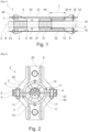
- a device 1 for absorbing the energy released by the local detensioning of a structural cable C, such as an external prestressing cable or a stay cable.
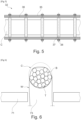
- Cable C may include, as seen more particularly on the figure 6 , reinforcements T embedded in a cementitious material B. This cable C extends along a longitudinal axis Z.
- the device 1 comprises a retaining collar 2, a hammer collar 31, a reaction element 15 connected to the retaining collar 2 by a connection system 20, and a sacrificial spacer extending between the hammer collar 31 and the reaction element 15.
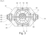
- the retaining collar 2 can be composed, as shown in the figure 2 , of two half-collars 3 (or half-shells), having over substantially their entire length flanges 4 assembled by means of a succession of bolts 5.
- the retaining collar 2 has a length greater than 3 times the external diameter of the cable C.
- Each half-collar 3 may have, as illustrated, longitudinal reinforcements 6.
- annular formwork cheeks axially close the space between the retaining collar 2 and the cable C, and create a substantially closed volume where a packing material P can be injected.
- These cheeks are for example held on the retaining collar 2 by screwing or any other suitable fixing means.
- Each half-collar 3 comprises at least one injection port 10 for injecting a wedging material P.
- This injection port 10 may be equipped, if necessary, with a quick or threaded connector, making it possible to connect a pipe connected to a pump to deliver the wedging material P, possibly under pressure.
- Each half-collar 3 may also comprise at least one vent 11, to allow air to escape during injection of the wedging material P, and to purge the excess wedging material P at the end of injection.
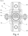
- the hammer collar 31 may have a structure similar to the retaining collar 2 and be composed of two half-collars 34 (or half-shells), having over substantially their entire length flanges 40 assembled by means of a succession of bolts 41.
- annular formwork cheeks As for the retaining collar 2, annular formwork cheeks, not visible in this figure, axially close the space between the hammer collar 31 and the cable C, and create a substantially closed volume where a wedging material P can be injected.
- the cheeks are for example held on the hammer collar 31 by screwing or any other suitable fixing means.
- Each half-collar 34 comprises at least one injection orifice 10 for injecting the wedging material P.
- Each half-collar 34 may also comprise at least one vent 11.
- Gaskets 50 are interposed between the flanges 3 of the retaining collar 2 and the flanges 40 of the hammer collar 31. Each gasket 50 extends inside the collar as far as the cable C.
- the material of the gasket 50 is for example an elastomer or a compressible material such as polystyrene or plywood.
- Rigid shims 51 may be arranged between the flanges, along their outer edge, to adjust the spacing between the flanges before injecting the shim material P.
- Claws 52 may grip the flanges on their outer edge, to hold them fixed in the absence of bolts or tightening of the latter.
- the device 1 may comprise, as illustrated in the figures 2 And 3 , shims 55 which are arranged between the cable C and the collars to keep them centered during the injection of the wedging material P, as will be detailed later.
- shims 55 are of preferably made beforehand with the same material as that which will be injected between the collars and the cementitious material B of the cable.
- the reaction element 15 may comprise a collar 33 composed of two half-collars 16 fixed together using bolts 75, and inside which the cable C can slide.
- the connecting system 20 comprises a set of bars 21, for example two in number as illustrated in the figure 1 , arranged on either side of the cable C. These bars 21 can be protected by sleeves, for example in HDPE, at least in the sectioning zone A of the cable C.
- the bars 21 each have threaded ends 23 engaged through support plates 25 of the reinforcements 6, nuts 28 screwed onto the ends 23 ensuring the maintenance of the spacing between the retaining collar 2 and the reaction element 25.
- the sacrificial spacer 32 is configured to deform under the effect of the movement of the hammer collar 31 towards the reaction element 15 during the detensioning of the cable C following its cutting, to absorb at least part of the energy released by this detensioning.
- the sacrificial spacer 32 is configured to deform plastically by buckling when the cable C is cut, and preferably has an initial length L greater than the displacement stroke of the hammer collar following detensioning.
- the typical elongation of the reinforcements is around 7 mm/m. Knowing the free length of the cable C, it is thus possible to determine the theoretical length L required for the sacrificial spacer 32.
- the sacrificial spacer 32 is a stack 35 composed of a plurality of metal plates 36 (or sheets), for example made of aluminum or steel.
- the sacrificial spacer 32 may have a U-shaped section in Omega or split into two stacks of plates 36, extending around the cable C, with facing parts connected by transverse threaded fasteners 37, or made of tubes, and associated with threaded rods, onto which nuts 38 are screwed.
- the sacrificial spacer 32 is in uniform contact on end plates 39 on the hammer collar 31 on the one hand and on the reaction element 15 on the other hand.
- the cable C can first be prepared by removing its outer sheath over segments of sufficient length to allow the fitting of the retaining collar 2 and the hammer collar 31.
- Circumferential cuts are preferably made at the ends of the segment concerned, followed by a longitudinal cut to open and remove the sheath segment.
- the cementitious material B can be struck with a hammer to remove any spalling and then bush-hammered using a manual or mechanical bush-hammer depending on the intensity required, to give sufficient roughness to the cementitious material B.
- This operation makes it possible to eliminate any areas of friable material (fragile elements that are easily separated from the mass of cementitious material B surrounding the reinforcements) and to ensure better adhesion with the wedging material P injected between the cementitious material B and each collar.
- cement material B is kept as is to avoid damaging reinforcement T before cutting.
- the half-collars of the retaining collar 2 and of the hammer collar 31 are positioned on the cable C.
- the collars are held in position with suitable supports in the lower part, supplemented by the shims 55.
- the latter allow each collar to be substantially centered around the cable C, this centering being desirable for the good distribution of forces in the device 1.
- the flexible gaskets 50 are interposed between the half-collars, and the rigid shims 51 are added locally and temporarily in order to maintain the distance between the half-collars, if necessary.
- the half-clamps are thus kept apart by an appropriate distance before tightening, which is for example 5 to 10 mm for a cable diameter C of around 100 mm.
- the seals 50 prevent the wedging material P from creating a rigid seal, i.e. a hard point, between the half-collars of the retaining collar 2 and the hammer collar 31, and prevent the wedging material P, after setting and hardening, from forming a tube which, by arching effect (circumferential pressure) would prevent adequate tightening, i.e. the application of a transverse clamping force on the reinforcements T and the cementitious material B by the bolts tightened on the joint plane of the collar(s).
- the bolts can be tightened slightly.
- the annular formwork cheeks are placed at each end of the half-collars to obtain a watertight closure of the volume defined between the half-collars and the cable C.
- the wedging material P can then be injected via the injection orifices 10 in fluid form into the volume delimited by each half-collar and the cable C. Thanks to its fluidity, the injected wedging material P can fill the volume optimally and, if necessary, penetrate into any cracks in the cementitious material B of the cable C.
- the wedging material P can be either a cement mortar or a polymer resin, which sets when solidifying to achieve a resistance suitable for transverse tightening of the clamps.
- any shims 51 present in the thickness of the flexible seal 50 and, optionally, the flexible seal 50 can be removed. Any excess shim material P present in this thickness is removed before hardening.
- Test specimens taken during the injection of the P packing material make it possible to assess its increase in resistance to guarantee a minimum compression value (for example 40 MPa for a cement packing material), before tightening the bolts of the collar(s) 2 and 15.
- a minimum compression value for example 40 MPa for a cement packing material
- the bolts are tightened successively, in an order that is favourable to good distribution of forces and likely to limit losses caused by non-simultaneous tightening.
- at least two successive passes are made in a so-called "staggered" pattern, alternating the two ends of the collar and the two sides.
- Tightening is preferably carried out using a hydraulic wrench whose tightening force or torque is calibrated according to the collar calculation note.
- reaction element 15 is arranged around the cable C and is connected to the retaining collar 2 by the connection system 20.
- the correct alignment of the retaining collar 2, the reaction element 15 and the traction bars 21 can then be checked. Additional rigid wedging can be applied if necessary.
- the sacrificial spacer 32 is arranged between the hammer collar 30 and the reaction element 15.
- the nuts 28 of the bars 21 are tightened in such a way that the sacrificial spacer 32 is in uniform contact on the end plates 39 of the hammer collar 31 on the one hand, of the reaction element 15 on the other hand.
- Cable C is then ready to be cut in sectioning zone A, using any means that does not risk damaging bars 21.
- a mechanical cutting method is preferred over cutting by heating (oxyacetylene torch) which may further expose the bars 21.
- heating oxygen (oxyacetylene torch) which may further expose the bars 21.
- a diamond wire saw W is used as illustrated in the figure. figure 6 , applying in 45.
- the diamond wire W can pass through openings 73 made on an element of the structure, for example a veil (or wall) of a bridge deck 71.
- the sectioning can thus be carried out by a remote operator.
- the length Li of the sacrificial spacer 32 is less than its length L before cutting, the spacer 32 having been deformed by buckling and plastic deformation.
- the invention is not limited to the example which has just been described.
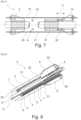
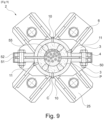
- the device is produced with a greater number of bars, for example equal to 4, as illustrated in the Figures 8 And 9 .
- each half-collar 3 can comprise a set of transverse stiffeners 7, connecting perpendicularly to the flanges 4 between the holes intended to receive the bolts 5.
- the collar(s) may be formed, where appropriate, of more than two collar parts.
- the element(s) arranged between the half-collars to form sealed volumes for injecting the packing material are left in place, and crushed during tightening of the collars.
Landscapes
- Engineering & Computer Science (AREA)
- Architecture (AREA)
- Civil Engineering (AREA)
- Structural Engineering (AREA)
- General Engineering & Computer Science (AREA)
- Mechanical Engineering (AREA)
- Bridges Or Land Bridges (AREA)
- Electric Cable Arrangement Between Relatively Moving Parts (AREA)
- Piles And Underground Anchors (AREA)
- Reinforcement Elements For Buildings (AREA)
Claims (13)
- Vorrichtung (1) zur Aufnahme der durch die lokale Entspannung eines Strukturkabels (C) freigesetzten Energie, welche umfasst:- mindestens eine erste Schelle (2), "Halteschelle" genannt, die an dem Kabel (C) zu befestigen ist,- mindestens eine zweite Schelle (31), "Hammerschelle" genannt, die an dem Kabel (C) zu befestigen ist, wobei die Halteschelle (2) und die Hammerschelle (31) auf dem Kabel (C) beiderseits des Schneidbereichs (A) angeordnet sind,- mindestens ein Reaktionselement (15), das derart um das Kabel (C) herum anzuordnen ist, dass sich die Hammerschelle (31) zwischen diesem Reaktionselement (15) und der Halteschelle (2) befindet, wobei das Kabel (C) im Inneren dieses Reaktionselements (15) gleiten kann,- ein Verbindungssystem (20) zwischen der Halteschelle (2) und dem Reaktionselement (15) zum Halten des Reaktionselements (15) in einem gegebenen Abstand von der Halteschelle (2),- mindestens ein zwischen dem Reaktionselement (15) und der Hammerschelle (31) angeordnetes Opfer-Abstandsstück (32), das dafür ausgelegt ist, sich unter der Wirkung der Bewegung der Hammerschelle (31) zum Reaktionselement (15) hin bei der Entspannung des Kabels (C) im Anschluss an dessen Zerschneiden zu verformen und wenigstens einen Teil der Energie aufzunehmen, die durch diese Entspannung freigesetzt wird.
- Vorrichtung nach Anspruch 1, wobei das Reaktionselement (15) eine Schelle (33) umfasst.
- Vorrichtung nach einem der vorhergehenden Ansprüche, wobei das Verbindungssystem (20) Stäbe (21) umfasst, welche die Halteschelle (2) und das Reaktionselement (15) verbinden.
- Vorrichtung nach einem der vorhergehenden Ansprüche, wobei das Opfer-Abstandsstück (32) mindestens eine Metallplatte (36), besser mindestens einen Stapel (35) von Platten, insbesondere Platten aus Stahl oder aus Aluminium, umfasst.
- Vorrichtung nach einem der vorhergehenden Ansprüche, welche mindestens eine Öffnung (10) zum Einspritzen eines Füllmaterials (P) in einen Raum, der sich zwischen der Halteschelle (2) und dem Kabel (C) einerseits und/oder der Hammerschelle (31) und dem Kabel (C) andererseits erstreckt, vor dem Festziehen der Schelle oder der Schellen (2; 31) umfasst.
- Vorrichtung nach dem vorhergehenden Anspruch, wobei sich die Einspritzöffnung (10) an der oder den Schellen (2; 31) befindet, wobei jede Schelle (2; 31), die mit einer Einspritzöffnung (10) versehen ist, vorzugsweise mindestens eine Entlüftungsöffnung (11) umfasst, um das Entweichen der Luft beim Füllen des Raumes zu ermöglichen.
- Vorrichtung nach einem der Ansprüche 5 und 6, wobei die Halteschelle (2) und/oder die Hammerschelle (31) zwei Halbschellen (3, 34) umfassen, mit mindestens einer Einspritzöffnung (10) und/oder einer Entlüftungsöffnung (11) pro Halbschelle (3, 34).
- Vorrichtung nach einem der vorhergehenden Ansprüche, wobei die Halteschelle (2) und/oder die Hammerschelle (31) zwei Halbschellen (3, 34) umfassen, wobei die Vorrichtung (1) mindestens eine flexible Dichtung (50) umfasst, die zwischen den zwei Halbschellen (3, 34) bis zum Kabel (C) angeordnet ist.
- Vorrichtung nach einem der vorhergehenden Ansprüche, welche Zentrierkeile (55) umfasst, die vor dem Einspritzen des Füllmaterials (P) zwischen der Halteschelle (2) und/oder der Hammerschelle (31) und dem Kabel (C) anzuordnen sind.
- Vorrichtung nach einem der vorhergehenden Ansprüche, wobei die Halteschelle (2) und/oder die Hammerschelle (31) eine Länge aufweisen, die mindestens größer oder gleich dem Dreifachen des Außendurchmessers des zu zerschneidenden Kabels (C) ist, vorzugsweise mindestens größer oder gleich dem Fünffachen des Außendurchmessers des zu zerschneidenden Kabels (C).
- Vorrichtung nach einem der vorhergehenden Ansprüche, wobei die Halteschelle (2) und/oder das Reaktionselement (15) Längsversteifungen (6) aufweisen.
- Verfahren zum Zerschneiden eines Strukturkabels (C) mittels einer Vorrichtung (1) nach einem der vorhergehenden Ansprüche, welches die folgenden Schritte umfasst:- Befestigen der Halteschelle (2) am Kabel (C),- Befestigen der Hammerschelle (31) am Kabel (C),- Anordnen des Reaktionselements (15), das mit der Halteschelle (2) durch das Verbindungssystem (20) verbunden ist, um das Kabel (C) herum,- Anordnen des Opfer-Abstandsstücks (32) zwischen der Hammerschelle (31) und dem Reaktionselement (15),- Zerschneiden des Kabels (C) im Schneidbereich (A), der sich zwischen der Halteschelle (2) und der Hammerschelle (31) befindet.
- Verfahren nach Anspruch 12, wobei die Vorrichtung (1) eine Vorrichtung nach Anspruch 5 oder 6 ist, wobei das Verfahren den Schritt des Einspritzens eines Füllmaterials (P) in die Räume umfasst, die zwischen der oder den Schellen (2, 31) und dem Kabel (C) ausgebildet sind, wobei dieses Einspritzen durch die Einspritzöffnung oder -Öffnungen (10) hindurch erfolgt.
Applications Claiming Priority (2)
| Application Number | Priority Date | Filing Date | Title |
|---|---|---|---|
| FR2010775A FR3115302B1 (fr) | 2020-10-21 | 2020-10-21 | Dispositif d’absorption de l’énergie libérée par la détension d’un câble de structure |
| PCT/EP2021/078428 WO2022084139A1 (fr) | 2020-10-21 | 2021-10-14 | Dispositif d'absorption de l'énergie libérée par la détension d'un câble de structure |
Publications (2)
| Publication Number | Publication Date |
|---|---|
| EP4232633A1 EP4232633A1 (de) | 2023-08-30 |
| EP4232633B1 true EP4232633B1 (de) | 2024-12-04 |
Family
ID=74045788
Family Applications (1)
| Application Number | Title | Priority Date | Filing Date |
|---|---|---|---|
| EP21790914.2A Active EP4232633B1 (de) | 2020-10-21 | 2021-10-14 | Vorrichtung zur aufnahme der beim nachspannen eines strukturkabels freigesetzten energie |
Country Status (7)
| Country | Link |
|---|---|
| EP (1) | EP4232633B1 (de) |
| KR (1) | KR20230112115A (de) |
| ES (1) | ES3014906T3 (de) |
| FR (1) | FR3115302B1 (de) |
| PL (1) | PL4232633T3 (de) |
| PT (1) | PT4232633T (de) |
| WO (1) | WO2022084139A1 (de) |
Family Cites Families (4)
| Publication number | Priority date | Publication date | Assignee | Title |
|---|---|---|---|---|
| FR2007394A1 (de) | 1968-04-05 | 1970-01-09 | Licentia Gmbh | |
| FR2839090B1 (fr) | 2002-04-29 | 2004-07-23 | Nantes Ecole Centrale | Procede de protection d'ouvrages d'art ou autres comprenant des cables tendus de precontrainte exterieure et/ou des cables porteurs et/ou des tirants |
| FR2904637A1 (fr) * | 2006-08-02 | 2008-02-08 | Freyssinet Soc Par Actions Sim | Procede de demontage d'un cable tendu, systeme et dispositifs associes. |
| DE102019102688A1 (de) * | 2019-02-04 | 2020-08-06 | Wobben Properties Gmbh | Vorrichtung und Verfahren zum Entspannen einer Spannlitze |
-
2020
- 2020-10-21 FR FR2010775A patent/FR3115302B1/fr active Active
-
2021
- 2021-10-14 PL PL21790914.2T patent/PL4232633T3/pl unknown
- 2021-10-14 KR KR1020237017153A patent/KR20230112115A/ko active Pending
- 2021-10-14 PT PT217909142T patent/PT4232633T/pt unknown
- 2021-10-14 ES ES21790914T patent/ES3014906T3/es active Active
- 2021-10-14 EP EP21790914.2A patent/EP4232633B1/de active Active
- 2021-10-14 WO PCT/EP2021/078428 patent/WO2022084139A1/fr not_active Ceased
Also Published As
| Publication number | Publication date |
|---|---|
| PL4232633T3 (pl) | 2025-04-28 |
| FR3115302A1 (fr) | 2022-04-22 |
| ES3014906T3 (en) | 2025-04-28 |
| FR3115302B1 (fr) | 2022-10-14 |
| WO2022084139A1 (fr) | 2022-04-28 |
| EP4232633A1 (de) | 2023-08-30 |
| PT4232633T (pt) | 2025-01-31 |
| KR20230112115A (ko) | 2023-07-26 |
Similar Documents
| Publication | Publication Date | Title |
|---|---|---|
| US8869476B2 (en) | Sealing arrangement | |
| JP5987067B2 (ja) | 内部拘束装置 | |
| FR3069555A1 (fr) | Ensemble ameliore comprenant un cable de structure et un dispositif de deviation | |
| EP4232633B1 (de) | Vorrichtung zur aufnahme der beim nachspannen eines strukturkabels freigesetzten energie | |
| FR2962186A1 (fr) | Assemblage d'un tube en materiau composite et d'une piece metallique tubulaire. | |
| EP3921557B1 (de) | Überbrückungsvorrichtungen und systeme und verfahren zu ihrer implementierung | |
| FR3112561A1 (fr) | Dispositif de pontage et procédé de détension et de découpe | |
| EP2868829B1 (de) | Verstärkungsverfahren eines Bauelements aus Holz durch den Zusammenbau eines nachgespannten Verstärkungsmoduls | |
| FR3119403A1 (fr) | Système de pontage et procédé de mise en œuvre | |
| FR2818676A1 (fr) | Procede de demontage d'un cable de precontrainte et dispositif pour la mise en oeuvre | |
| FR2956184A1 (fr) | Procede de restauration d'une canalisation | |
| EP1501984B1 (de) | Sicherungsverfahren für ingenieurbauten mit spanngliedern | |
| EP4276243B1 (de) | Verfahren zur lokalen übernahme der spannung eines vorspannkabels und system zur überbrückung eines vorspannkabels mit diesem verfahren | |
| EP0221817A2 (de) | Befestigungsvorrichtung zum Verbinden von Riemen, solch eine Vorrichtung verwendendes Verbindungsverfahren und nach diesem Verfahren verbundene Riemen | |
| FR2524030A1 (fr) | Tete d'ancrage pour tirant composite precomprime a raccourcissement progressif | |
| HK40096693A (en) | Device for absorbing the energy released by the detensioning of a structural cable | |
| HK40096693B (en) | Device for absorbing the energy released by the detensioning of a structural cable | |
| FR2811002A1 (fr) | Procede et systeme de mise en traction d'un dispositif de renforcement de structure | |
| EP3508654A1 (de) | Pfahl aus verbundmaterial | |
| FR3025544A1 (fr) | Temoin de serrage d'un support pour coffrage | |
| EP0511053B1 (de) | Verstärkung einer Rohrverbindung | |
| EP3073018A1 (de) | Erdbebensicheres zugankersystem für die feste verbindung von betonfundamenten eines bauwerks | |
| HK40057059A (en) | Cable drain wire | |
| HK40057059B (en) | Cable drain wire | |
| FR3114823A1 (fr) | Système de pont modulaire et son procédé de fabrication |
Legal Events
| Date | Code | Title | Description |
|---|---|---|---|
| STAA | Information on the status of an ep patent application or granted ep patent |
Free format text: STATUS: UNKNOWN |
|
| STAA | Information on the status of an ep patent application or granted ep patent |
Free format text: STATUS: THE INTERNATIONAL PUBLICATION HAS BEEN MADE |
|
| PUAI | Public reference made under article 153(3) epc to a published international application that has entered the european phase |
Free format text: ORIGINAL CODE: 0009012 |
|
| STAA | Information on the status of an ep patent application or granted ep patent |
Free format text: STATUS: REQUEST FOR EXAMINATION WAS MADE |
|
| 17P | Request for examination filed |
Effective date: 20230522 |
|
| AK | Designated contracting states |
Kind code of ref document: A1 Designated state(s): AL AT BE BG CH CY CZ DE DK EE ES FI FR GB GR HR HU IE IS IT LI LT LU LV MC MK MT NL NO PL PT RO RS SE SI SK SM TR |
|
| DAV | Request for validation of the european patent (deleted) | ||
| DAX | Request for extension of the european patent (deleted) | ||
| REG | Reference to a national code |
Ref country code: HK Ref legal event code: DE Ref document number: 40096693 Country of ref document: HK |
|
| GRAP | Despatch of communication of intention to grant a patent |
Free format text: ORIGINAL CODE: EPIDOSNIGR1 |
|
| STAA | Information on the status of an ep patent application or granted ep patent |
Free format text: STATUS: GRANT OF PATENT IS INTENDED |
|
| INTG | Intention to grant announced |
Effective date: 20240527 |
|
| GRAS | Grant fee paid |
Free format text: ORIGINAL CODE: EPIDOSNIGR3 |
|
| GRAA | (expected) grant |
Free format text: ORIGINAL CODE: 0009210 |
|
| STAA | Information on the status of an ep patent application or granted ep patent |
Free format text: STATUS: THE PATENT HAS BEEN GRANTED |
|
| AK | Designated contracting states |
Kind code of ref document: B1 Designated state(s): AL AT BE BG CH CY CZ DE DK EE ES FI FR GB GR HR HU IE IS IT LI LT LU LV MC MK MT NL NO PL PT RO RS SE SI SK SM TR |
|
| REG | Reference to a national code |
Ref country code: CH Ref legal event code: EP |
|
| REG | Reference to a national code |
Ref country code: DE Ref legal event code: R096 Ref document number: 602021022959 Country of ref document: DE |
|
| REG | Reference to a national code |
Ref country code: IE Ref legal event code: FG4D Free format text: LANGUAGE OF EP DOCUMENT: FRENCH |
|
| REG | Reference to a national code |
Ref country code: PT Ref legal event code: SC4A Ref document number: 4232633 Country of ref document: PT Date of ref document: 20250131 Kind code of ref document: T Free format text: AVAILABILITY OF NATIONAL TRANSLATION Effective date: 20250128 |
|
| P01 | Opt-out of the competence of the unified patent court (upc) registered |
Free format text: CASE NUMBER: APP_2502/2025 Effective date: 20250115 |
|
| REG | Reference to a national code |
Ref country code: LT Ref legal event code: MG9D |
|
| REG | Reference to a national code |
Ref country code: NL Ref legal event code: MP Effective date: 20241204 |
|
| PG25 | Lapsed in a contracting state [announced via postgrant information from national office to epo] |
Ref country code: HR Free format text: LAPSE BECAUSE OF FAILURE TO SUBMIT A TRANSLATION OF THE DESCRIPTION OR TO PAY THE FEE WITHIN THE PRESCRIBED TIME-LIMIT Effective date: 20241204 |
|
| PG25 | Lapsed in a contracting state [announced via postgrant information from national office to epo] |
Ref country code: FI Free format text: LAPSE BECAUSE OF FAILURE TO SUBMIT A TRANSLATION OF THE DESCRIPTION OR TO PAY THE FEE WITHIN THE PRESCRIBED TIME-LIMIT Effective date: 20241204 |
|
| PG25 | Lapsed in a contracting state [announced via postgrant information from national office to epo] |
Ref country code: BG Free format text: LAPSE BECAUSE OF FAILURE TO SUBMIT A TRANSLATION OF THE DESCRIPTION OR TO PAY THE FEE WITHIN THE PRESCRIBED TIME-LIMIT Effective date: 20241204 |
|
| PG25 | Lapsed in a contracting state [announced via postgrant information from national office to epo] |
Ref country code: NO Free format text: LAPSE BECAUSE OF FAILURE TO SUBMIT A TRANSLATION OF THE DESCRIPTION OR TO PAY THE FEE WITHIN THE PRESCRIBED TIME-LIMIT Effective date: 20250304 |
|
| PG25 | Lapsed in a contracting state [announced via postgrant information from national office to epo] |
Ref country code: LV Free format text: LAPSE BECAUSE OF FAILURE TO SUBMIT A TRANSLATION OF THE DESCRIPTION OR TO PAY THE FEE WITHIN THE PRESCRIBED TIME-LIMIT Effective date: 20241204 Ref country code: GR Free format text: LAPSE BECAUSE OF FAILURE TO SUBMIT A TRANSLATION OF THE DESCRIPTION OR TO PAY THE FEE WITHIN THE PRESCRIBED TIME-LIMIT Effective date: 20250305 |
|
| PG25 | Lapsed in a contracting state [announced via postgrant information from national office to epo] |
Ref country code: RS Free format text: LAPSE BECAUSE OF FAILURE TO SUBMIT A TRANSLATION OF THE DESCRIPTION OR TO PAY THE FEE WITHIN THE PRESCRIBED TIME-LIMIT Effective date: 20250304 |
|
| PG25 | Lapsed in a contracting state [announced via postgrant information from national office to epo] |
Ref country code: NL Free format text: LAPSE BECAUSE OF FAILURE TO SUBMIT A TRANSLATION OF THE DESCRIPTION OR TO PAY THE FEE WITHIN THE PRESCRIBED TIME-LIMIT Effective date: 20241204 |
|
| REG | Reference to a national code |
Ref country code: AT Ref legal event code: MK05 Ref document number: 1748284 Country of ref document: AT Kind code of ref document: T Effective date: 20241204 |
|
| PG25 | Lapsed in a contracting state [announced via postgrant information from national office to epo] |
Ref country code: SM Free format text: LAPSE BECAUSE OF FAILURE TO SUBMIT A TRANSLATION OF THE DESCRIPTION OR TO PAY THE FEE WITHIN THE PRESCRIBED TIME-LIMIT Effective date: 20241204 |
|
| PG25 | Lapsed in a contracting state [announced via postgrant information from national office to epo] |
Ref country code: IS Free format text: LAPSE BECAUSE OF FAILURE TO SUBMIT A TRANSLATION OF THE DESCRIPTION OR TO PAY THE FEE WITHIN THE PRESCRIBED TIME-LIMIT Effective date: 20250404 |
|
| PG25 | Lapsed in a contracting state [announced via postgrant information from national office to epo] |
Ref country code: EE Free format text: LAPSE BECAUSE OF FAILURE TO SUBMIT A TRANSLATION OF THE DESCRIPTION OR TO PAY THE FEE WITHIN THE PRESCRIBED TIME-LIMIT Effective date: 20241204 |
|
| PG25 | Lapsed in a contracting state [announced via postgrant information from national office to epo] |
Ref country code: RO Free format text: LAPSE BECAUSE OF FAILURE TO SUBMIT A TRANSLATION OF THE DESCRIPTION OR TO PAY THE FEE WITHIN THE PRESCRIBED TIME-LIMIT Effective date: 20241204 Ref country code: AT Free format text: LAPSE BECAUSE OF FAILURE TO SUBMIT A TRANSLATION OF THE DESCRIPTION OR TO PAY THE FEE WITHIN THE PRESCRIBED TIME-LIMIT Effective date: 20241204 |
|
| PG25 | Lapsed in a contracting state [announced via postgrant information from national office to epo] |
Ref country code: SK Free format text: LAPSE BECAUSE OF FAILURE TO SUBMIT A TRANSLATION OF THE DESCRIPTION OR TO PAY THE FEE WITHIN THE PRESCRIBED TIME-LIMIT Effective date: 20241204 |
|
| PG25 | Lapsed in a contracting state [announced via postgrant information from national office to epo] |
Ref country code: CZ Free format text: LAPSE BECAUSE OF FAILURE TO SUBMIT A TRANSLATION OF THE DESCRIPTION OR TO PAY THE FEE WITHIN THE PRESCRIBED TIME-LIMIT Effective date: 20241204 |
|
| PG25 | Lapsed in a contracting state [announced via postgrant information from national office to epo] |
Ref country code: IT Free format text: LAPSE BECAUSE OF FAILURE TO SUBMIT A TRANSLATION OF THE DESCRIPTION OR TO PAY THE FEE WITHIN THE PRESCRIBED TIME-LIMIT Effective date: 20241204 |
|
| REG | Reference to a national code |
Ref country code: DE Ref legal event code: R097 Ref document number: 602021022959 Country of ref document: DE |
|
| PG25 | Lapsed in a contracting state [announced via postgrant information from national office to epo] |
Ref country code: SE Free format text: LAPSE BECAUSE OF FAILURE TO SUBMIT A TRANSLATION OF THE DESCRIPTION OR TO PAY THE FEE WITHIN THE PRESCRIBED TIME-LIMIT Effective date: 20241204 |
|
| PG25 | Lapsed in a contracting state [announced via postgrant information from national office to epo] |
Ref country code: DK Free format text: LAPSE BECAUSE OF FAILURE TO SUBMIT A TRANSLATION OF THE DESCRIPTION OR TO PAY THE FEE WITHIN THE PRESCRIBED TIME-LIMIT Effective date: 20241204 |
|
| PLBE | No opposition filed within time limit |
Free format text: ORIGINAL CODE: 0009261 |
|
| STAA | Information on the status of an ep patent application or granted ep patent |
Free format text: STATUS: NO OPPOSITION FILED WITHIN TIME LIMIT |
|
| REG | Reference to a national code |
Ref country code: CH Ref legal event code: L10 Free format text: ST27 STATUS EVENT CODE: U-0-0-L10-L00 (AS PROVIDED BY THE NATIONAL OFFICE) Effective date: 20251015 |
|
| REG | Reference to a national code |
Ref country code: CH Ref legal event code: U11 Free format text: ST27 STATUS EVENT CODE: U-0-0-U10-U11 (AS PROVIDED BY THE NATIONAL OFFICE) Effective date: 20251101 |
|
| 26N | No opposition filed |
Effective date: 20250905 |
|
| PGFP | Annual fee paid to national office [announced via postgrant information from national office to epo] |
Ref country code: PT Payment date: 20251002 Year of fee payment: 5 |
|
| PGFP | Annual fee paid to national office [announced via postgrant information from national office to epo] |
Ref country code: GB Payment date: 20251022 Year of fee payment: 5 |
|
| PGFP | Annual fee paid to national office [announced via postgrant information from national office to epo] |
Ref country code: FR Payment date: 20251030 Year of fee payment: 5 |
|
| PGFP | Annual fee paid to national office [announced via postgrant information from national office to epo] |
Ref country code: TR Payment date: 20251007 Year of fee payment: 5 Ref country code: BE Payment date: 20251021 Year of fee payment: 5 |
|
| PGFP | Annual fee paid to national office [announced via postgrant information from national office to epo] |
Ref country code: CH Payment date: 20251101 Year of fee payment: 5 |
|
| PGFP | Annual fee paid to national office [announced via postgrant information from national office to epo] |
Ref country code: PL Payment date: 20251003 Year of fee payment: 5 |
|
| PGFP | Annual fee paid to national office [announced via postgrant information from national office to epo] |
Ref country code: ES Payment date: 20251216 Year of fee payment: 5 |