EP4232288B1 - Durchsetzte fluidische elemente und schaltungselemente in einer fluidischen matrize - Google Patents
Durchsetzte fluidische elemente und schaltungselemente in einer fluidischen matrize Download PDFInfo
- Publication number
- EP4232288B1 EP4232288B1 EP20958903.5A EP20958903A EP4232288B1 EP 4232288 B1 EP4232288 B1 EP 4232288B1 EP 20958903 A EP20958903 A EP 20958903A EP 4232288 B1 EP4232288 B1 EP 4232288B1
- Authority
- EP
- European Patent Office
- Prior art keywords
- fluidic
- elements
- fluid
- die
- circuit elements
- Prior art date
- Legal status (The legal status is an assumption and is not a legal conclusion. Google has not performed a legal analysis and makes no representation as to the accuracy of the status listed.)
- Active
Links
Images


Classifications
-
- B—PERFORMING OPERATIONS; TRANSPORTING
- B41—PRINTING; LINING MACHINES; TYPEWRITERS; STAMPS
- B41J—TYPEWRITERS; SELECTIVE PRINTING MECHANISMS, i.e. MECHANISMS PRINTING OTHERWISE THAN FROM A FORME; CORRECTION OF TYPOGRAPHICAL ERRORS
- B41J2/00—Typewriters or selective printing mechanisms characterised by the printing or marking process for which they are designed
- B41J2/005—Typewriters or selective printing mechanisms characterised by the printing or marking process for which they are designed characterised by bringing liquid or particles selectively into contact with a printing material
- B41J2/01—Ink jet
- B41J2/135—Nozzles
- B41J2/14—Structure thereof only for on-demand ink jet heads
- B41J2/14016—Structure of bubble jet print heads
- B41J2/14032—Structure of the pressure chamber
- B41J2/1404—Geometrical characteristics
-
- B—PERFORMING OPERATIONS; TRANSPORTING
- B41—PRINTING; LINING MACHINES; TYPEWRITERS; STAMPS
- B41J—TYPEWRITERS; SELECTIVE PRINTING MECHANISMS, i.e. MECHANISMS PRINTING OTHERWISE THAN FROM A FORME; CORRECTION OF TYPOGRAPHICAL ERRORS
- B41J2/00—Typewriters or selective printing mechanisms characterised by the printing or marking process for which they are designed
- B41J2/005—Typewriters or selective printing mechanisms characterised by the printing or marking process for which they are designed characterised by bringing liquid or particles selectively into contact with a printing material
- B41J2/01—Ink jet
- B41J2/135—Nozzles
- B41J2/145—Arrangement thereof
-
- B—PERFORMING OPERATIONS; TRANSPORTING
- B41—PRINTING; LINING MACHINES; TYPEWRITERS; STAMPS
- B41J—TYPEWRITERS; SELECTIVE PRINTING MECHANISMS, i.e. MECHANISMS PRINTING OTHERWISE THAN FROM A FORME; CORRECTION OF TYPOGRAPHICAL ERRORS
- B41J2202/00—Embodiments of or processes related to ink-jet or thermal heads
- B41J2202/01—Embodiments of or processes related to ink-jet heads
- B41J2202/12—Embodiments of or processes related to ink-jet heads with ink circulating through the whole print head
-
- B—PERFORMING OPERATIONS; TRANSPORTING
- B41—PRINTING; LINING MACHINES; TYPEWRITERS; STAMPS
- B41J—TYPEWRITERS; SELECTIVE PRINTING MECHANISMS, i.e. MECHANISMS PRINTING OTHERWISE THAN FROM A FORME; CORRECTION OF TYPOGRAPHICAL ERRORS
- B41J2202/00—Embodiments of or processes related to ink-jet or thermal heads
- B41J2202/01—Embodiments of or processes related to ink-jet heads
- B41J2202/13—Heads having an integrated circuit
Definitions
- a fluid dispensing system can dispense fluid towards a target.
- a fluid dispensing system can include a printing system, such as a two-dimensional (2D) printing system or a three-dimensional (3D) printing system.
- a printing system can include printhead devices that include fluidic actuators to cause dispensing of printing fluids.
- US20150124024 discloses a fluid ejection device including a thin-film layer formed over a substrate.
- US20130106961 discloses a printhead with a moveable membrane.
- US20190047287 discloses a liquid ejection head comprising an ejection opening row along a first direction.
- US2001040596 discloses a high speed, high resolution inkjet printhead.
- the fluidic actuators include thermal-based fluidic actuators including heating elements, such as resistive heaters. When a heating element is activated, the heating element produces heat that can cause vaporization of a fluid to cause nucleation of a vapor bubble (e.g., a steam bubble) proximate the thermal-based fluidic actuator that in turn causes dispensing of a quantity of fluid, such as ejection from an orifice of a nozzle or flow through a fluid conduit or fluid chamber.
- a fluidic actuator may be a deflecting-type fluidic actuator such as a piezoelectric membrane based fluidic actuator that when activated applies a mechanical force to dispense a quantity of fluid.
- each nozzle can include an orifice through which fluid is dispensed from a fluid chamber, in response to activation of a fluidic actuator.
- Each fluid chamber provides the fluid to be dispensed by the respective nozzle.
- a fluid dispensing device can include a microfluidic pump that has a fluid chamber.
- a fluidic actuator can be an ejecting-type fluidic actuator to cause ejection of a fluid, such as through an orifice of a nozzle, or a non-ejecting-type fluidic actuator to cause displacement of a fluid.
- a fluid dispensing device can be in the form of a fluidic die.
- a "die” refers to an assembly where various layers are formed onto a substrate to fabricate circuitry, fluid chambers, and fluid conduits. Multiple fluidic dies can be mounted or attached to a support structure.
- a fluidic die can be a printhead die, which can be mounted to a print cartridge, a carriage assembly, and so forth.
- a printhead die includes nozzles through which a printing fluid (e.g., an ink, a liquid agent used in a 3D printing system, etc.) can be dispensed towards a target (e.g., a print medium such as a paper sheet, a transparency foil, a fabric, etc., or a print bed including 3D parts being formed by a 3D printing system to build a 3D object).
- a printing fluid e.g., an ink, a liquid agent used in a 3D printing system, etc.
- a target e.g., a print medium such as a paper sheet, a transparency foil, a fabric, etc., or a print bed including 3D parts being formed by a 3D printing system to build a 3D object.
- a fluidic die includes fluidic elements and circuitry that control fluid dispensing operations of the fluidic elements.
- the circuitry includes logic that is responsive to address signals and control signals to produce output signals that control switching elements used for activating respective fluidic actuators in the fluid elements.
- a fluidic die includes fluidic elements contained in fluidic architecture regions that do not include circuitry with active devices.
- the fluidic die is partitioned into the fluidic architecture regions and circuit regions that are outside of the fluidic architecture regions.
- the circuit regions include circuit elements that include active devices.
- an “active device” can refer to a device that can be switched between different states, such as an on state at which electrical current flows through the device, and off state at which electrical current does not flow through the device (or the amount of electrical current flow is negligible or below a specified threshold).
- An example of an active device is a transistor, such as a field effect transistor (FET).
- FET field effect transistor
- a transistor has a gate that is connected to a signal (“gate signal”) to control the state of the transistor. When the gate signal is at an active level (e.g., a low voltage or a high voltage depending on the type of transistor used), the transistor turns on to conduct electrical current between two other nodes of the transistor (e.g., a drain node and a source node of an FET).
- the gate signal is at an inactive level (e.g., a high voltage or a low voltage depending on the type of transistor used), then no electrical current flows through the transistor (or the amount of electrical current through the transistor is negligible or below a specified threshold).
- the gate signal to the transistor can be set at an intermediate level between the active level or the inactive level, which causes the transistor to conduct an intermediate amount of electrical current.
- an active device is a diode. If the voltage across two nodes of the diode exceeds a threshold voltage, then the diode turns on to conduct electrical current through the diode. However, if the voltage across that the two nodes of the diode is less than the threshold voltage, and the diode remains off.
- Partitioning a fluidic die between fluidic architecture regions and circuit regions may simplify the interface between the circuit elements and the fluidic elements, or may be performed because of the arrangement of fluid feed slots in the fluidic die.
- a fluid feed slot refers to a fluid conduit that may run along an entire actuator column of the fluidic die. The fluid feed slot is used to carry fluid to and from the fluidic elements of the fluidic die.
- Certain types of fluidic dies may employ a sparse arrangement of fluidic elements (the fluidic elements are arranged in patterns of lower density than fluidic elements in other fluidic dies). If a fluidic die has a sparse arrangement of fluidic elements, then the fluidic architecture regions would consume a larger area of the fluidic die than fluidic architecture regions of a fluidic die with a denser arrangement of fluidic elements. Given the same size of a fluidic die and assuming a same quantity of fluidic elements is used (compared to another fluidic die with a denser arrangement of fluidic elements), the larger fluidic architecture regions of the sparse arrangement would result in smaller circuit regions in the fluidic die, which leads to greater compaction of circuit elements. In some cases, there may not be sufficient space for circuit elements in a fluidic die with a sparse arrangement of fluidic elements.
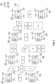
- a fluidic die 102 includes fluidic elements in the form of fluidic cells 104.
- a "fluidic cell” refers to a collection of flow structures, and the fluidic cell can be repeated across the fluidic die 102, such as to form an array.
- the fluidic cells 104 are interspersed with circuit elements along multiple different axes across a substrate 110 (of the fluidic die 102) on which the fluidic cells 104 and the circuit elements are commonly formed. Fluidic cells are interspersed with circuit elements if along a given axis, successive fluidic cells are separated by circuit element(s), and successive circuit elements are separated by fluidic cell(s).
- the different axes include a first axis 106 and a second axis 108 that is substantially orthogonal to the first axis 106.
- the first axis 106 and the second axis 108 are substantially orthogonal if the first axis 106 has an angle with respect to the second axis 108 that is in any of the following ranges: between 45° and 135°, between 60° in 120°, between 75° and 115°, and so forth.
- Each circuit element in Fig. 1 is represented as a block with a "C" in the block.
- Each circuit element C includes an active device or multiple active devices.
- active devices of a circuit element C can be interconnected to provide a logical operation, such as a logical AND, a logical OR, a logical inversion, and so forth.
- Active devices of a circuit element C can also be used to perform other types of operations, such as to provide a latch, a register, or another storage element, to provide a variable resistance, and so forth.
- the active devices of a circuit element C can be used to implement analog circuitry.
- examples of active devices include transistors and diodes, or any other device that can be switched between different states in response to an input signal.
- the fluidic cells 104 are arranged in a two-dimensional array, along the first axis 106 and the second axis 108.
- the array of fluidic cells 104 can have a different pattern; for example, instead of a row or column that is generally parallel to the axis 106 or 108, respectively, a line of fluidic cells 104 may be slanted with respect to the axis 106 or 108.
- the fluidic cells 104 instead of the fluidic cells 104 having a regular pattern, the fluidic cells 104 may have an irregular pattern or even a random pattern across the substrate 110 of the fluidic die 102.
- a first quantity of circuit elements interspersed in regions between the fluidic cells 104 along the axis 106 is greater than a specified number (e.g., 10, 20, etc.)
- a second quantity of circuit elements interspersed in regions between the fluidic cells 104 along the axis 108 is greater than a specified number (e.g., 10, 20, etc.).
- Each fluidic cell 104 includes a respective fluid feed hole 112 and a fluid chamber 114 into which a fluid can be fed through the fluid feed hole 112, in the example of Fig. 1 .
- the fluidic cell 104 can also include a fluidic actuator 115, which when activated causes the fluid in the fluid chamber to be dispensed through an orifice (not shown in Fig. 1 ) of the fluidic cell 104.
- a fluidic cell 104 can include multiple fluid feed holes and/or multiple orifices.
- an array of fluid feed holes 112 is arranged in multiple dimensions (e.g., along the axes 106 and 108).
- the array of fluid feed holes 112 include distinct fluid feed holes that extend along a first dimension of the multiple dimensions, and distinct fluid feed holes that extend along a different second dimension of the multiple dimensions.
- “Distinct" fluid feed holes refer to fluid feed holes that are individually separate from one another, as opposed to a fluid feed slot that can extend a relatively long length to feed multiple fluidic cells, such as a column of fluidic cells.
- the fluid feed holes 112 are used to communicate fluid with respective fluid chambers of the fluidic cells 104.
- the fluidic die 102 has multiple outer edges 102-1, 102-2, 102-3, and 102-4, which collectively form a general rectangle (when viewed from the top or bottom) in the example of Fig. 1 .
- An "outer edge" of a fluidic die refers to a segment of an outermost boundary of the fluidic die 102. In other examples, the fluidic die 102 can have different shapes.
- either the first dimension or the second dimension of the multiple dimensions along which the array of fluid feed holes 112 is arranged can be parallel to an outer edge (one of 102-1, 102-2, 102-3, and 102-4) of the fluidic die 102. In further examples, both the first dimension and the second dimension are parallel to respective outer edges of the fluidic die 102.
- each of multiple fluid feed holes along the first dimension is distinct from multiple fluid feed holes along the second dimension (e.g., along the axis 108).
- each of fluid feed holes 112 in the fluidic cells 104 in the second column 158 and the third column 160 is distinct from multiple fluid feed holes 112 in the fluidic cells 104 in the second row 152 and last row 154 of the first column 156 of the array.
- the first row 150 has multiple fluidic cells (in columns other than the first column 156) that are distinct from multiple fluidic cells in the first column 156 (in rows other than the first row 150).
- the fluidic die 102 can be mounted on a support structure (e.g., a print cartridge, a carriage, etc.), which is relatively moveable with respect to a target to which fluid of the fluidic die 102 is to be dispensed.
- the target can be a print substrate onto which printing fluid is to be dispensed in a 2D printing system, or a 3D build part onto which liquid agents are to be dispensed during a 3D build operation of a 3D printing system.
- the fluidic die 102 is relatively moveable with respect to the target if either or both of the fluidic die 102 and the target is (are) moveable.
- the fluidic die 102 is relatively moveable with respect to the target along a direction that is parallel to either axis 106 or 108.
- Regions that are without flow structures are provided between successive fluidic cells 104 along both the first axis 106 and the second axis 108. Such regions are not used by the fluidic cells 104 for fluid flow.
- the circuit elements are placed in the regions between the fluidic cells 104. As a result, the circuit elements are interspersed with the fluidic cells 104 along both the axes 106 and 108.
- the elements of the fluidic cells 104 being interspersed with the circuit elements result in an alternating arrangement of fluidic elements and circuit elements along the different axes 106 and 108.
- the fluidic cells 104 and the circuit elements are formed on a common substrate, i.e., the substrate 110 of the fluidic die 102.
- the substrate 110 can be a silicon substrate, or a substrate formed of another semiconductor material or a different material.
- Forming the fluidic cells 104 and the circuit elements on a common substrate refers to forming layers of the fluidic cells 104 and the circuit elements as part of an integrated circuit processing flow for a single integrated circuit device, which in Fig. 1 is the fluidic die 102. Circuit elements and fluidic cells 104 formed on different substrates, such as being part of different integrated circuit devices formed using different integrated circuit process flows, would not be considered to be formed on a common substrate.
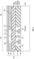
- Fig. 2 is a schematic sectional view of a portion of a fluidic die 200 attached to an interposer 240 or another type of structure, according to further examples.
- the fluidic die 200 includes layers 206, 208, 218, and 224.
- a "layer" (any of 206, 208, 218, and 224) can include a single layer or multiple layers, possibly formed of different materials.
- the layers 224 and 218 make up a substrate for the fluidic die 200.
- the layers 224 and 218 can include epoxy-based photoresist (e.g., SU-8), silicon, another semiconductor material, or a different material.
- Fig. 2 shows layers of a fluidic cell 204 and a circuit element (202 represents active circuit element layers, such as layers of an active device or multiple active devices).
- the circuit element layers 202 can include any or some combination of metal layers, polysilicon layers, doped regions, and so forth. Doped regions can be formed into the layer 218. Metal layers and polysilicon layers of active devices can be formed over the doped regions.
- a thin film interconnect layer or layers 230 (including a metal or another electrically conductive material) can be formed over the layer 218, where the thin film interconnect layer 230 can form an electrical contact or via to electrically connect to an active device.
- the fluidic cell 204 can be arranged in similar manner as the fluidic cell 104 of Fig. 1 (i.e., multiple fluidic cells 204 can be arranged in an array along multiple axes, such as the axes 106 and 108 shown in Fig. 1 ).
- the circuit elements formed using circuit element layers 202 can also be interspersed with the fluidic cells 204 along multiple different axes.
- the fluidic cell 204 includes an orifice layer 206 in which an orifice 207 (or multiple orifices) is (are) formed.
- a chamber layer 208 is provided under the orifice layer 206, and the chamber layer 208 defines a fluid chamber 210.
- the layers 206 and 208 can include any of various different types of materials, such as epoxy, silicon, and so forth.
- a fluidic actuator 212 is formed over the layer 218 in the fluid chamber 210. If the fluidic actuator is a resistive heater, the fluidic actuator 212 can be formed using a thin film of an electrically resistive material (such as tungsten-silicon nitride, polysilicon or any other material that exhibits electrical resistivity). Activation of the fluidic actuator 212 causes fluid in the fluid chamber 210 to be expelled through the orifice 207.
- an electrically resistive material such as tungsten-silicon nitride, polysilicon or any other material that exhibits electrical resistivity
- the circuit element layers 202 are formed on the substrate (including layers 224 and 218) of the fluidic die 200 before various layers of the fluidic cell 204.
- a layer is on the substrate if the layer is directly on the substrate, or if the layer is supported by the substrate through other layer(s).
- the chamber layer 208 is formed over the layer 218 as well as over thin film layers (the thin film layer for the fluidic actuator 212 and the thin film interconnect layer 230).
- the active circuit element layers 202 are formed over the substrate (including layers 224 and 218) prior to the layers 208 and 206 for the fluidic cell 204.
- the thin film layers (the thin film layer for the fluidic actuator 212 and the thin film interconnect layer 230) are formed, followed by the fluidic cell layers 208 and 206 over the active circuit element layers 202.
- two fluid feed holes 214 and 216 are formed in a feed hole layer 218 (by etching the feed hole layer 218 to form the fluid feed holes, for example).
- the fluid feed hole 214 is an inlet fluid feed hole that allows fluid to flow into the fluid chamber 210.
- the fluid feed hole 216 is an outlet fluid feed hole from which fluid in the fluid chamber 210 flows.
- the inlet fluid feed hole 214 is in communication with a high pressure chamber 220
- the outlet fluid feed hole 216 is in communication with a low pressure chamber 222.
- the high pressure chamber 220 and the low pressure chamber 222 are formed in a layer 224 (by etching the layer 224 to form the chambers 220 and 222, for example).
- the high pressure chamber 220 is divided from the low pressure chamber 222 by a wall 221 of the layer 224.
- the pressure in the high pressure chamber 220 and the pressure in the low pressure chamber 222 can be controlled by respective pressure regulators (not shown).
- the high pressure chamber 220 has a pressure that is higher than the pressure of the low pressure chamber 222.
- the arrangement of the fluidic cell 204 allows for fluid recirculation along fluid path 226. Fluid can flow from the high pressure chamber 220 into the inlet fluid feed hole 214, which is then passed to the fluid chamber 210. The fluid exits from the fluid chamber 210 through the outlet fluid feed hole 216 to the low pressure chamber 222.
- Recirculation can be performed to carry any contaminants that may be in the fluid chamber 210 out of the fluid chamber 210. In other examples, recirculation of fluid through the fluid chamber 210 can be performed for other purposes.
Landscapes
- Physics & Mathematics (AREA)
- Geometry (AREA)
- Micromachines (AREA)
Claims (15)
- Fluidische Matrize (102, 200, 500), die umfasst:ein Substrat (110, 502)eine Anordnung von fluidischen Teilen (504) zum Abgeben eines Fluids, wobei jedes fluidischen Teil der fluidischen Teile (504) ein fluidisches Bedienungselement (115, 212, 520) und eine Fluidkammer (114, 210, 522) umfasst;ein Array von Fluidzufuhrlöchern (112, 214, 216, 310, 312) in einer Vielzahl von Abmessungen quer über das Substrat (110, 502) zum Übertragen des Fluids mit den fluidischen Teilen (504), wobei sich jedes von mehreren Fluidzufuhrlöchern (112, 214, 216, 310, 312) entlang einer ersten Abmessung der Vielzahl von Abmessungen quer über das Substrat (110, 502) von mehreren Fluidzufuhrlöchern (112, 214, 216, 310, 312) entlang einer zweiten Abmessung der Vielzahl von Abmessungen quer über das Substrat (110, 502) unterscheidet; undSchaltungsteile (510), die in Bereichen zwischen den fluidischen Teilen (504) entlang verschiedener Achsen (106, 108, 306, 308) der fluidischen Matrize (102, 200, 500) eingestreut sind, was zu einer abwechselnden Anordnung von fluidischen Teilen (504) und Schaltungsteilen (510) entlang der verschiedenen Achsen (106, 108, 306, 308) führt, wobei jedes Schaltungsteil (510) der Schaltungsteile (510) eine aktive Vorrichtung umfasst undwobei die fluidischen Teile (504) und die Schaltungsteile (510) an einem gemeinsamen Substrat (110, 502) ausgebildet sind.
- Fluidische Matrize (102, 200, 500) nach Anspruch 1, wobei die aktive Vorrichtung einen Transistor umfasst.
- Fluidische Matrize (102, 200, 500) nach Anspruch 1, wobei die aktive Vorrichtung eine Diode umfasst.
- Fluidische Matrize (102, 200, 500) nach Anspruch 1, wobei eine erste Menge von Schaltungsteilen (510), die in Bereichen zwischen den fluidischen Teilen (504) entlang einer ersten Achse (506) der verschiedenen Achsen (106, 108, 306, 308) quer über das Substrat (110, 502) eingestreut sind, mehr als 10 beträgt, und eine zweite Menge von Schaltungsteilen (510), die in Bereichen zwischen den fluidischen Teilen (504) entlang einer zweiten Achse (106, 108, 306, 308) der verschiedenen Achsen (106, 108, 306, 308) quer über das Substrat (110, 502) eingestreut sind, mehr als 10 beträgt.
- Fluidische Matrize (102, 200, 500) nach Anspruch 1, wobei die erste Abmessung der Vielzahl von Abmessungen parallel zu einer Außenkante der fluidischen Matrize (102, 200, 500) ist.
- Fluidische Matrize (102, 200, 500) nach Anspruch 1, wobei jedes fluidische Teil der fluidischen Teile (504) ferner ein Einlassfluidzufuhrloch (112, 214, 216, 310, 312) und ein Auslassfluidzufuhrloch (112, 214, 216, 310, 312) zum Rezirkulieren eines Fluids durch die Fluidkammer (114, 210, 522) des fluidischen Teils umfasst.
- Fluidische Matrize (102, 200, 500) nach Anspruch 1, wobei jedes fluidische Teil der fluidischen Teile (504) ferner eine Öffnung (207, 314, 316) umfasst, durch die ein Fluid von der Fluidkammer (114, 210, 522) des fluidischen Teil abgegeben wird.
- Fluidische Matrize (102, 200, 500) nach Anspruch 1, wobei die Anordnung der fluidischen Teile (504) umfasst:erste fluidische Teile (504), die sich entlang einer ersten Achse (506) der verschiedenen Achsen (106, 108, 306, 308) quer über das Substrat (110, 502) erstrecken, wobei erste Bereiche ohne Strömungsstrukturen zwischen aufeinanderfolgenden fluidischen Teilen (504) der ersten fluidischen Teile (504) bereitgestellt sind, undzweite fluidische Teile (504), die sich entlang einer zweiten Achse (106, 108, 306, 308) der verschiedenen Achsen (106, 108, 306, 308) quer über das Substrat (110, 502) erstrecken, wobei zweite Bereiche ohne Strömungsstrukturen zwischen aufeinanderfolgenden fluidischen Teilen (504) der zweiten fluidischen Teile (504) bereitgestellt sind, undwobei die Schaltungsteile (510) umfassen:erste Schaltungsteile (510) in den ersten Bereichen undzweite Schaltungsteile (510) in den zweiten Bereichen.
- Fluidische Matrize (102, 200, 500) nach Anspruch 1, wobei die verschiedenen Achsen (106, 108, 306, 308) quer über das Substrat (110, 502) im Wesentlichen orthogonale Achsen (106, 108, 306, 308) sind.
- Fluidische Matrize (102, 200, 500) nach Anspruch 1, wobei Schichten der fluidischen Teile (504) über Schichten der Schaltungsteile (510) an dem gemeinsamen Substrat (110, 502) ausgebildet sind.
- Verfahren zum Ausbilden einer fluidischen Matrize (102, 200, 500), das umfasst:Ausbilden von Schichten für Schaltungsteile (510) an einem Substrat (110, 502), wobei jedes Schaltungsteil (510) der Schaltungsteile (510) eine aktive Vorrichtung umfasst;Ausbilden von Schichten für fluidische Teile (504) über den Schichten für die Schaltungsteile (510), wobei die fluidischen Teile (504) zum Abgeben eines Fluids dienen, eine Anordnung der fluidischen Teile (504) quer über das Substrat (110, 502) Bereiche ohne Strömungsstrukturen zwischen aufeinanderfolgenden fluidischen Teilen (504) aufweist und jedes fluidische Teil der fluidischen Teile (504) ein fluidisches Bedienungselement (115, 212, 520) und eine Fluidkammer (114, 210, 522) umfasst;Einstreuen der Schaltungsteile (510) in den Bereichen zwischen den fluidischen Teilen (504) entlang verschiedener Achsen (106, 108, 306, 308) der fluidischen Matrize (102, 200, 500), was zu einer abwechselnden Anordnung von fluidischen Teilen (504) und Schaltungsteilen (510) entlang der verschiedenen Achsen (106, 108, 306, 308) führt; undAusbilden eines Arrays von Fluidzufuhrlöchern (112, 214, 216, 310, 312) in einer Vielzahl von Abmessungen zum Übertragen des Fluids mit den fluidischen Teilen (504), wobei sich jedes von mehreren Fluidzufuhrlöchern (112, 214, 216, 310, 312) entlang einer ersten Abmessung der Vielzahl von Abmessungen von mehreren Fluidzufuhrlöchern (112, 214, 216, 310, 312) entlang einer zweiten Abmessung der Vielzahl von Abmessungen unterscheidet.
- Verfahren nach Anspruch 11, wobei ein Ausbilden der Schichten für die Schaltungsteile (510) ein Ausbilden der Schichten für Transistoren oder Dioden umfasst.
- Verfahren nach Anspruch 11, wobei die verschiedenen Achsen (106, 108, 306, 308) eine erste Achse (506) und eine zweite Achse (106, 108, 306, 308), die im Wesentlichen orthogonal zu der ersten Achse (506) ist, umfassen und wobei ein Einstreuen der Schaltungsteile (510) in die Bereiche ein Abwechseln der Schaltungsteile (510) und der fluidischen Teile (504) entlang jeder Achse (106, 108, 306, 308) der ersten Achse (506) und der zweiten Achse (106, 108, 306, 308) umfasst.
- Fluidische Matrize (102, 200, 500) nach Anspruch 1,
wobei die Schaltungsteile mehr als 10 erste Schaltungsteile entlang der ersten Achse in ersten Bereichen zwischen aufeinanderfolgenden ersten fluidischen Teilen und mehr als 10 zweite Schaltungsteile entlang der zweiten Achse in zweiten Bereichen zwischen aufeinanderfolgenden zweiten fluidischen Teilen umfassen, und wobei die fluidischen Teile (504) und die Schaltungsteile (510) Schichten einer integrierten Schaltung umfassen, die an dem Substrat (110, 502) gemeinsam ausgebildet sind. - Fluidische Matrize (102, 200, 500) nach Anspruch 14, die ferner umfasst:
ein Array von Fluidzufuhrlöchern (112, 214, 216, 310, 312) in einer Vielzahl von Abmessungen zum Übertragen des Fluids mit den fluidischen Teilen (504), wobei eine erste Abmessung der Vielzahl von Abmessungen parallel zu einer Außenkante der fluidischen Matrize (102, 200, 500) ist.
Applications Claiming Priority (1)
| Application Number | Priority Date | Filing Date | Title |
|---|---|---|---|
| PCT/US2020/057109 WO2022086560A1 (en) | 2020-10-23 | 2020-10-23 | Interspersed fluidic elements and circuit elements in a fluidic die |
Publications (3)
| Publication Number | Publication Date |
|---|---|
| EP4232288A1 EP4232288A1 (de) | 2023-08-30 |
| EP4232288A4 EP4232288A4 (de) | 2023-11-22 |
| EP4232288B1 true EP4232288B1 (de) | 2024-12-04 |
Family
ID=81291903
Family Applications (1)
| Application Number | Title | Priority Date | Filing Date |
|---|---|---|---|
| EP20958903.5A Active EP4232288B1 (de) | 2020-10-23 | 2020-10-23 | Durchsetzte fluidische elemente und schaltungselemente in einer fluidischen matrize |
Country Status (4)
| Country | Link |
|---|---|
| US (1) | US12257837B2 (de) |
| EP (1) | EP4232288B1 (de) |
| CN (1) | CN116490368B (de) |
| WO (1) | WO2022086560A1 (de) |
Family Cites Families (19)
| Publication number | Priority date | Publication date | Assignee | Title |
|---|---|---|---|---|
| US5648805A (en) | 1992-04-02 | 1997-07-15 | Hewlett-Packard Company | Inkjet printhead architecture for high speed and high resolution printing |
| US5790149A (en) | 1993-06-03 | 1998-08-04 | Seiko Epson Corporation | Ink jet recording head |
| KR100374204B1 (ko) * | 2000-05-03 | 2003-03-04 | 한국과학기술원 | 2차원 노즐배치를 갖는 잉크젯 프린트헤드 및 그 제조방법 |
| US7488056B2 (en) | 2004-04-19 | 2009-02-10 | Hewlett--Packard Development Company, L.P. | Fluid ejection device |
| US7758171B2 (en) | 2007-03-19 | 2010-07-20 | Eastman Kodak Company | Aerodynamic error reduction for liquid drop emitters |
| KR20120040239A (ko) | 2009-07-10 | 2012-04-26 | 후지필름 디마틱스, 인크. | 조밀 충진을 위한 마이크로일렉트로미케니칼 시스템 젯팅 구조 |
| CN102905903B (zh) * | 2010-05-27 | 2015-04-22 | 惠普发展公司,有限责任合伙企业 | 打印头和相关方法和系统 |
| JP2012016892A (ja) | 2010-07-08 | 2012-01-26 | Canon Inc | 液体吐出記録ヘッド |
| US9610772B2 (en) | 2011-03-31 | 2017-04-04 | Hewlett-Packard Development Company, L.P. | Printhead assembly |
| JP5871738B2 (ja) | 2011-09-13 | 2016-03-01 | 東芝テック株式会社 | インクジェットヘッドおよびインクジェット記録装置 |
| WO2013048382A1 (en) | 2011-09-28 | 2013-04-04 | Hewlett-Packard Development Company, L.P. | Slot-to-slot circulation in a fluid ejection device |
| US9352568B2 (en) * | 2012-07-24 | 2016-05-31 | Hewlett-Packard Development Company, L.P. | Fluid ejection device with particle tolerant thin-film extension |
| WO2016089372A1 (en) | 2014-12-02 | 2016-06-09 | Hewlett-Packard Development Company, L.P. | Printhead |
| JP2016117234A (ja) | 2014-12-22 | 2016-06-30 | キヤノン株式会社 | 液体吐出ヘッド、液体吐出装置及び液体の吐出方法 |
| WO2016137490A1 (en) * | 2015-02-27 | 2016-09-01 | Hewlett-Packard Development Company, L.P. | Fluid ejection device with fluid feed holes |
| US10179453B2 (en) * | 2016-01-08 | 2019-01-15 | Canon Kabushiki Kaisha | Liquid ejection head and liquid ejection apparatus |
| GB2563719B (en) * | 2016-03-04 | 2019-12-11 | Xaar Technology Ltd | Droplet deposition head and manifold component therefor |
| CN111542437B (zh) * | 2018-03-12 | 2021-12-28 | 惠普发展公司,有限责任合伙企业 | 流体喷射设备 |
| CN113396066B (zh) * | 2019-02-06 | 2022-12-09 | 惠普发展公司,有限责任合伙企业 | 用于打印头的管芯及在管芯上形成裂纹检测器迹线的方法 |
-
2020
- 2020-10-23 EP EP20958903.5A patent/EP4232288B1/de active Active
- 2020-10-23 CN CN202080106492.6A patent/CN116490368B/zh active Active
- 2020-10-23 US US18/032,797 patent/US12257837B2/en active Active
- 2020-10-23 WO PCT/US2020/057109 patent/WO2022086560A1/en not_active Ceased
Also Published As
| Publication number | Publication date |
|---|---|
| CN116490368A (zh) | 2023-07-25 |
| CN116490368B (zh) | 2025-03-07 |
| US12257837B2 (en) | 2025-03-25 |
| US20230382109A1 (en) | 2023-11-30 |
| EP4232288A1 (de) | 2023-08-30 |
| EP4232288A4 (de) | 2023-11-22 |
| WO2022086560A1 (en) | 2022-04-28 |
Similar Documents
| Publication | Publication Date | Title |
|---|---|---|
| US8672463B2 (en) | Bypass fluid circulation in fluid ejection devices | |
| US20180036763A1 (en) | Microfluidic device for thermally spraying a liquid containing pigments and/or aroma prone to aggregation or deposition | |
| EP4232288B1 (de) | Durchsetzte fluidische elemente und schaltungselemente in einer fluidischen matrize | |
| US11565521B2 (en) | Fluid ejection device with a portioning wall | |
| US20180186151A1 (en) | Alternative ground lines for inter-slot grounding | |
| US12233647B2 (en) | Arrangements of circuit elements and fluidic elements | |
| US20090002422A1 (en) | Structure for monolithic thermal inkjet array | |
| WO2022086562A1 (en) | Interspersed sense elements and fluidic elements in a fluidic die | |
| EP3463905B1 (de) | Flüssigkeitsausstoss über verschiedene feldeffekttransistoren | |
| US12576633B2 (en) | Matching electrically conductive line resistances to switches in fluidic dies | |
| US11285731B2 (en) | Fluid feed hole port dimensions | |
| US20080122896A1 (en) | Inkjet printhead with backside power return conductor | |
| US20210039391A1 (en) | Fluid ejection unit with circulation loop and fluid bypass | |
| JP2020168745A (ja) | 液体吐出ヘッド及び液体吐出装置 | |
| US20230056907A1 (en) | Fluidic dies with thermal sensors on membrane | |
| WO2021183104A1 (en) | Fluidic die with adjacent and orthogonal bond pad regions | |
| JP2010505657A (ja) | 3端子切り換え素子を有するアレイ・プリントヘッド | |
| WO2021183101A1 (en) | Fluidic die with bond pads having different heights |
Legal Events
| Date | Code | Title | Description |
|---|---|---|---|
| STAA | Information on the status of an ep patent application or granted ep patent |
Free format text: STATUS: THE INTERNATIONAL PUBLICATION HAS BEEN MADE |
|
| PUAI | Public reference made under article 153(3) epc to a published international application that has entered the european phase |
Free format text: ORIGINAL CODE: 0009012 |
|
| STAA | Information on the status of an ep patent application or granted ep patent |
Free format text: STATUS: REQUEST FOR EXAMINATION WAS MADE |
|
| 17P | Request for examination filed |
Effective date: 20230413 |
|
| AK | Designated contracting states |
Kind code of ref document: A1 Designated state(s): AL AT BE BG CH CY CZ DE DK EE ES FI FR GB GR HR HU IE IS IT LI LT LU LV MC MK MT NL NO PL PT RO RS SE SI SK SM TR |
|
| A4 | Supplementary search report drawn up and despatched |
Effective date: 20231023 |
|
| RIC1 | Information provided on ipc code assigned before grant |
Ipc: B41J 2/145 20060101ALI20231017BHEP Ipc: B41J 2/14 20060101AFI20231017BHEP |
|
| DAV | Request for validation of the european patent (deleted) | ||
| DAX | Request for extension of the european patent (deleted) | ||
| GRAP | Despatch of communication of intention to grant a patent |
Free format text: ORIGINAL CODE: EPIDOSNIGR1 |
|
| STAA | Information on the status of an ep patent application or granted ep patent |
Free format text: STATUS: GRANT OF PATENT IS INTENDED |
|
| RIC1 | Information provided on ipc code assigned before grant |
Ipc: B41J 2/145 20060101ALI20240819BHEP Ipc: B41J 2/14 20060101AFI20240819BHEP |
|
| INTG | Intention to grant announced |
Effective date: 20240902 |
|
| GRAS | Grant fee paid |
Free format text: ORIGINAL CODE: EPIDOSNIGR3 |
|
| GRAA | (expected) grant |
Free format text: ORIGINAL CODE: 0009210 |
|
| STAA | Information on the status of an ep patent application or granted ep patent |
Free format text: STATUS: THE PATENT HAS BEEN GRANTED |
|
| AK | Designated contracting states |
Kind code of ref document: B1 Designated state(s): AL AT BE BG CH CY CZ DE DK EE ES FI FR GB GR HR HU IE IS IT LI LT LU LV MC MK MT NL NO PL PT RO RS SE SI SK SM TR |
|
| REG | Reference to a national code |
Ref country code: CH Ref legal event code: EP |
|
| REG | Reference to a national code |
Ref country code: DE Ref legal event code: R096 Ref document number: 602020042823 Country of ref document: DE |
|
| REG | Reference to a national code |
Ref country code: IE Ref legal event code: FG4D |
|
| REG | Reference to a national code |
Ref country code: LT Ref legal event code: MG9D |
|
| REG | Reference to a national code |
Ref country code: NL Ref legal event code: MP Effective date: 20241204 |
|
| PG25 | Lapsed in a contracting state [announced via postgrant information from national office to epo] |
Ref country code: HR Free format text: LAPSE BECAUSE OF FAILURE TO SUBMIT A TRANSLATION OF THE DESCRIPTION OR TO PAY THE FEE WITHIN THE PRESCRIBED TIME-LIMIT Effective date: 20241204 |
|
| PG25 | Lapsed in a contracting state [announced via postgrant information from national office to epo] |
Ref country code: FI Free format text: LAPSE BECAUSE OF FAILURE TO SUBMIT A TRANSLATION OF THE DESCRIPTION OR TO PAY THE FEE WITHIN THE PRESCRIBED TIME-LIMIT Effective date: 20241204 |
|
| PG25 | Lapsed in a contracting state [announced via postgrant information from national office to epo] |
Ref country code: BG Free format text: LAPSE BECAUSE OF FAILURE TO SUBMIT A TRANSLATION OF THE DESCRIPTION OR TO PAY THE FEE WITHIN THE PRESCRIBED TIME-LIMIT Effective date: 20241204 |
|
| PG25 | Lapsed in a contracting state [announced via postgrant information from national office to epo] |
Ref country code: ES Free format text: LAPSE BECAUSE OF FAILURE TO SUBMIT A TRANSLATION OF THE DESCRIPTION OR TO PAY THE FEE WITHIN THE PRESCRIBED TIME-LIMIT Effective date: 20241204 |
|
| PG25 | Lapsed in a contracting state [announced via postgrant information from national office to epo] |
Ref country code: NO Free format text: LAPSE BECAUSE OF FAILURE TO SUBMIT A TRANSLATION OF THE DESCRIPTION OR TO PAY THE FEE WITHIN THE PRESCRIBED TIME-LIMIT Effective date: 20250304 |
|
| PG25 | Lapsed in a contracting state [announced via postgrant information from national office to epo] |
Ref country code: LV Free format text: LAPSE BECAUSE OF FAILURE TO SUBMIT A TRANSLATION OF THE DESCRIPTION OR TO PAY THE FEE WITHIN THE PRESCRIBED TIME-LIMIT Effective date: 20241204 Ref country code: GR Free format text: LAPSE BECAUSE OF FAILURE TO SUBMIT A TRANSLATION OF THE DESCRIPTION OR TO PAY THE FEE WITHIN THE PRESCRIBED TIME-LIMIT Effective date: 20250305 |
|
| PG25 | Lapsed in a contracting state [announced via postgrant information from national office to epo] |
Ref country code: RS Free format text: LAPSE BECAUSE OF FAILURE TO SUBMIT A TRANSLATION OF THE DESCRIPTION OR TO PAY THE FEE WITHIN THE PRESCRIBED TIME-LIMIT Effective date: 20250304 |
|
| PG25 | Lapsed in a contracting state [announced via postgrant information from national office to epo] |
Ref country code: NL Free format text: LAPSE BECAUSE OF FAILURE TO SUBMIT A TRANSLATION OF THE DESCRIPTION OR TO PAY THE FEE WITHIN THE PRESCRIBED TIME-LIMIT Effective date: 20241204 |
|
| REG | Reference to a national code |
Ref country code: AT Ref legal event code: MK05 Ref document number: 1747771 Country of ref document: AT Kind code of ref document: T Effective date: 20241204 |
|
| PG25 | Lapsed in a contracting state [announced via postgrant information from national office to epo] |
Ref country code: SM Free format text: LAPSE BECAUSE OF FAILURE TO SUBMIT A TRANSLATION OF THE DESCRIPTION OR TO PAY THE FEE WITHIN THE PRESCRIBED TIME-LIMIT Effective date: 20241204 |
|
| PG25 | Lapsed in a contracting state [announced via postgrant information from national office to epo] |
Ref country code: PL Free format text: LAPSE BECAUSE OF FAILURE TO SUBMIT A TRANSLATION OF THE DESCRIPTION OR TO PAY THE FEE WITHIN THE PRESCRIBED TIME-LIMIT Effective date: 20241204 |
|
| PG25 | Lapsed in a contracting state [announced via postgrant information from national office to epo] |
Ref country code: IS Free format text: LAPSE BECAUSE OF FAILURE TO SUBMIT A TRANSLATION OF THE DESCRIPTION OR TO PAY THE FEE WITHIN THE PRESCRIBED TIME-LIMIT Effective date: 20250404 |
|
| PG25 | Lapsed in a contracting state [announced via postgrant information from national office to epo] |
Ref country code: PT Free format text: LAPSE BECAUSE OF FAILURE TO SUBMIT A TRANSLATION OF THE DESCRIPTION OR TO PAY THE FEE WITHIN THE PRESCRIBED TIME-LIMIT Effective date: 20250404 |
|
| PG25 | Lapsed in a contracting state [announced via postgrant information from national office to epo] |
Ref country code: EE Free format text: LAPSE BECAUSE OF FAILURE TO SUBMIT A TRANSLATION OF THE DESCRIPTION OR TO PAY THE FEE WITHIN THE PRESCRIBED TIME-LIMIT Effective date: 20241204 |
|
| PG25 | Lapsed in a contracting state [announced via postgrant information from national office to epo] |
Ref country code: RO Free format text: LAPSE BECAUSE OF FAILURE TO SUBMIT A TRANSLATION OF THE DESCRIPTION OR TO PAY THE FEE WITHIN THE PRESCRIBED TIME-LIMIT Effective date: 20241204 Ref country code: AT Free format text: LAPSE BECAUSE OF FAILURE TO SUBMIT A TRANSLATION OF THE DESCRIPTION OR TO PAY THE FEE WITHIN THE PRESCRIBED TIME-LIMIT Effective date: 20241204 |
|
| PG25 | Lapsed in a contracting state [announced via postgrant information from national office to epo] |
Ref country code: SK Free format text: LAPSE BECAUSE OF FAILURE TO SUBMIT A TRANSLATION OF THE DESCRIPTION OR TO PAY THE FEE WITHIN THE PRESCRIBED TIME-LIMIT Effective date: 20241204 |
|
| PG25 | Lapsed in a contracting state [announced via postgrant information from national office to epo] |
Ref country code: CZ Free format text: LAPSE BECAUSE OF FAILURE TO SUBMIT A TRANSLATION OF THE DESCRIPTION OR TO PAY THE FEE WITHIN THE PRESCRIBED TIME-LIMIT Effective date: 20241204 |
|
| PG25 | Lapsed in a contracting state [announced via postgrant information from national office to epo] |
Ref country code: IT Free format text: LAPSE BECAUSE OF FAILURE TO SUBMIT A TRANSLATION OF THE DESCRIPTION OR TO PAY THE FEE WITHIN THE PRESCRIBED TIME-LIMIT Effective date: 20241204 |
|
| REG | Reference to a national code |
Ref country code: DE Ref legal event code: R097 Ref document number: 602020042823 Country of ref document: DE |
|
| PG25 | Lapsed in a contracting state [announced via postgrant information from national office to epo] |
Ref country code: SE Free format text: LAPSE BECAUSE OF FAILURE TO SUBMIT A TRANSLATION OF THE DESCRIPTION OR TO PAY THE FEE WITHIN THE PRESCRIBED TIME-LIMIT Effective date: 20241204 |
|
| PG25 | Lapsed in a contracting state [announced via postgrant information from national office to epo] |
Ref country code: DK Free format text: LAPSE BECAUSE OF FAILURE TO SUBMIT A TRANSLATION OF THE DESCRIPTION OR TO PAY THE FEE WITHIN THE PRESCRIBED TIME-LIMIT Effective date: 20241204 |
|
| PLBE | No opposition filed within time limit |
Free format text: ORIGINAL CODE: 0009261 |
|
| STAA | Information on the status of an ep patent application or granted ep patent |
Free format text: STATUS: NO OPPOSITION FILED WITHIN TIME LIMIT |
|
| 26N | No opposition filed |
Effective date: 20250905 |
|
| PGFP | Annual fee paid to national office [announced via postgrant information from national office to epo] |
Ref country code: DE Payment date: 20250923 Year of fee payment: 6 |