EP4231764A1 - Method and device for relay communication on sidelink - Google Patents
Method and device for relay communication on sidelink Download PDFInfo
- Publication number
- EP4231764A1 EP4231764A1 EP21880429.2A EP21880429A EP4231764A1 EP 4231764 A1 EP4231764 A1 EP 4231764A1 EP 21880429 A EP21880429 A EP 21880429A EP 4231764 A1 EP4231764 A1 EP 4231764A1
- Authority
- EP
- European Patent Office
- Prior art keywords
- terminal
- relay
- connection configuration
- communication
- message
- Prior art date
- Legal status (The legal status is an assumption and is not a legal conclusion. Google has not performed a legal analysis and makes no representation as to the accuracy of the status listed.)
- Pending
Links
- 238000004891 communication Methods 0.000 title claims abstract description 290
- 238000000034 method Methods 0.000 title claims abstract description 63
- 238000005259 measurement Methods 0.000 claims description 10
- 230000004044 response Effects 0.000 claims description 4
- 230000001960 triggered effect Effects 0.000 claims description 3
- 230000005540 biological transmission Effects 0.000 abstract description 18
- 238000005516 engineering process Methods 0.000 description 40
- 230000011664 signaling Effects 0.000 description 30
- 230000010267 cellular communication Effects 0.000 description 22
- 238000010586 diagram Methods 0.000 description 12
- 230000006870 function Effects 0.000 description 3
- 238000012545 processing Methods 0.000 description 3
- 230000000737 periodic effect Effects 0.000 description 2
- 230000002776 aggregation Effects 0.000 description 1
- 238000004220 aggregation Methods 0.000 description 1
- 230000004075 alteration Effects 0.000 description 1
- 230000000694 effects Effects 0.000 description 1
- 230000007774 longterm Effects 0.000 description 1
- 238000012986 modification Methods 0.000 description 1
- 230000004048 modification Effects 0.000 description 1
- 238000012544 monitoring process Methods 0.000 description 1
- 230000003252 repetitive effect Effects 0.000 description 1
- 238000006467 substitution reaction Methods 0.000 description 1
Images


Classifications
-
- H—ELECTRICITY
- H04—ELECTRIC COMMUNICATION TECHNIQUE
- H04W—WIRELESS COMMUNICATION NETWORKS
- H04W40/00—Communication routing or communication path finding
- H04W40/02—Communication route or path selection, e.g. power-based or shortest path routing
- H04W40/12—Communication route or path selection, e.g. power-based or shortest path routing based on transmission quality or channel quality
-
- H—ELECTRICITY
- H04—ELECTRIC COMMUNICATION TECHNIQUE
- H04W—WIRELESS COMMUNICATION NETWORKS
- H04W40/00—Communication routing or communication path finding
- H04W40/02—Communication route or path selection, e.g. power-based or shortest path routing
- H04W40/22—Communication route or path selection, e.g. power-based or shortest path routing using selective relaying for reaching a BTS [Base Transceiver Station] or an access point
-
- H—ELECTRICITY
- H04—ELECTRIC COMMUNICATION TECHNIQUE
- H04W—WIRELESS COMMUNICATION NETWORKS
- H04W76/00—Connection management
- H04W76/10—Connection setup
- H04W76/14—Direct-mode setup
-
- H—ELECTRICITY
- H04—ELECTRIC COMMUNICATION TECHNIQUE
- H04W—WIRELESS COMMUNICATION NETWORKS
- H04W76/00—Connection management
- H04W76/20—Manipulation of established connections
- H04W76/23—Manipulation of direct-mode connections
-
- H—ELECTRICITY
- H04—ELECTRIC COMMUNICATION TECHNIQUE
- H04W—WIRELESS COMMUNICATION NETWORKS
- H04W88/00—Devices specially adapted for wireless communication networks, e.g. terminals, base stations or access point devices
- H04W88/02—Terminal devices
- H04W88/04—Terminal devices adapted for relaying to or from another terminal or user
-
- H—ELECTRICITY
- H04—ELECTRIC COMMUNICATION TECHNIQUE
- H04W—WIRELESS COMMUNICATION NETWORKS
- H04W92/00—Interfaces specially adapted for wireless communication networks
- H04W92/16—Interfaces between hierarchically similar devices
- H04W92/18—Interfaces between hierarchically similar devices between terminal devices
Definitions
- the present disclosure relates to a sidelink communication technique, and more particularly, to a technique for configuring a connection between terminals performing relay communications.
- a fifth-generation (5G) communication system (e.g., New Radio (NR) communication system) which uses a frequency band higher than a frequency band of a fourth-generation (4G) communication system (e.g., Long Term Evolution (LTE) communication system or LTE-Advanced (LTE-A) communication system) as well as the frequency band of the 4G communication system has been considered for processing of wireless data.
- the 5G communication system can support Enhanced Mobile Broadband (eMBB) communications, Ultra-Reliable and Low-Latency communications (URLLC), massive Machine Type Communications (mMTC), and the like.
- eMBB Enhanced Mobile Broadband
- URLLC Ultra-Reliable and Low-Latency communications
- mMTC massive Machine Type Communications
- the 4G communication system and 5G communication system can support Vehicle-to-Everything (V2X) communications.
- V2X communications supported in a cellular communication system such as the 4G communication system, the 5G communication system, and the like, may be referred to as "Cellular-V2X (C-V2X) communications.”
- the V2X communications (e.g., C-V2X communications) may include Vehicle-to-Vehicle (V2V) communications, Vehicle-to-Infrastructure (V2I) communications, Vehicle-to-Pedestrian (V2P) communication, Vehicle-to-Network (V2N) communication, and the like.
- the V2X communications may be performed based on sidelink communication technologies (e.g., Proximity-based Services (ProSe) communication technology, Device-to-Device (D2D) communication technology, or the like).
- sidelink communication technologies e.g., Proximity-based Services (ProSe) communication technology, Device-to-Device (D2D) communication technology, or the like.
- ProSe Proximity-based Services
- D2D Device-to-Device
- sidelink channels for vehicles participating in V2V communications can be established, and communications between the vehicles can be performed using the sidelink channels.
- Sidelink communication may be performed using configured grant (CG) resources.
- the CG resources may be periodically configured, and periodic data (e.g., periodic sidelink data) may be transmitted using the CG resources.
- sidelink communication between a transmitting terminal and a receiving terminal may be performed in a relay manner.
- Relay communication performed on sidelinks may be referred to as SL relay communication.
- SL relay communication a connection configuration method between the transmitting terminal and a relay terminal and a connection configuration method between the receiving terminal and the relay terminal are required, but the above-described connection configuration methods have not been defined.
- the present disclosure is directed to providing a method and an apparatus for configuring connections between terminals performing SL relay communications.
- An operation method of a transmitting terminal may comprise: performing sidelink (SL) communication with a receiving terminal; in response to determining that SL relay communication is required, performing a connection configuration operation with a relay terminal; transmitting, to the receiving terminal, a first message including connection configuration information for the SL relay communication; receiving, from the receiving terminal, a second message indicating that connection configuration between the receiving terminal and the relay terminal has been completed; and performing the SL relay communication with the receiving terminal through the relay terminal.
- SL sidelink
- the SL relay communication may be determined to be required, and the one or more preconfigured conditions may include at least one of a case when a number of negative acknowledgments (NACKs) received from the receiving terminal is p or more, a case when a channel quality between the transmitting terminal and the receiving terminal is equal to or less than a reference value, a case when an indicator requesting the SL relay communication is received from the receiving terminal, or a case when the SL relay communication is triggered by a base station.
- NACKs negative acknowledgments
- connection configuration operation between the transmitting terminal and the relay terminal may be performed when a base station indicates to enable the SL relay communication.
- the performing of the connection configuration operation with the relay terminal may comprise: performing a measurement operation on signals received from one or more neighboring terminals; determining one neighboring terminal among the one or more neighboring terminals as the relay terminal based on a result of the measurement operation; and configuring a connection with the relay terminal.
- the connection configuration information may include at least one of an identifier of the relay terminal, information indicating that connection configuration between the transmitting terminal and the relay terminal has been completed, or a number for identifying data last transmitted by the transmitting terminal.
- the second message may include at least one of an identifier of the relay terminal, or information indicating that connection configuration between the receiving terminal and the relay terminal has been completed.
- the first message may be a radio resource control (RRC) reconfiguration sidelink message or sidelink control information (SCI)
- RRC radio resource control
- SCI sidelink control information
- the operation method may further comprise releasing connection configuration between the transmitting terminal and the receiving terminal when the SL relay communication is performed.
- An operation method of a receiving terminal may comprise: performing sidelink (SL) communication with a transmitting terminal; receiving, from the transmitting terminal, a first message including connection configuration information for SL relay communication; performing a connection configuration operation with a relay terminal indicated by the connection configuration information; and transmitting, to the transmitting terminal, a second message including a result of the connection configuration operation.
- SL sidelink
- the operation method may further comprise performing the SL relay communication with the transmitting terminal when the second message indicates that the connection configuration operation has been completed.
- the operation method may further comprise performing the SL communication with the transmitting terminal without the relay terminal when the second message indicates that the connection configuration operation has failed.
- connection configuration operation between the receiving terminal and the relay terminal may be performed when the base station indicates to enable the SL relay communication.
- the connection configuration information may include at least one of an identifier of the relay terminal, information indicating that connection configuration between the transmitting terminal and the relay terminal has been completed, or a number for identifying data last transmitted by the transmitting terminal.
- the performing of the connection configuration information with the relay terminal may comprise: identifying a second identifier of a neighboring terminal by receiving a signal from the neighboring terminal; comparing the second identifier with a first identifier of the relay terminal indicated by the connection configuration information; and configuring a connection with the relay terminal when the second identifier is identical to the first identifier.
- the first message may be a radio resource control (RRC) reconfiguration sidelink message or sidelink control information (SCI)
- RRC radio resource control
- SCI sidelink control information
- a transmitting terminal may comprise: a processor; a memory electronically communicating with the processor; and instructions stored in the memory. When executed by the processor, the instructions may cause the transmitting terminal to perform: performing sidelink (SL) communication with a receiving terminal; in response to determining that SL relay communication is required, performing a connection configuration operation with a relay terminal; transmitting, to the receiving terminal, a first message including connection configuration information for the SL relay communication; receiving, from the receiving terminal, a second message indicating that connection configuration between the receiving terminal and the relay terminal has been completed; and performing the SL relay communication with the receiving terminal through the relay terminal.
- SL sidelink
- the instructions may further cause the transmitting terminal to perform: releasing connection configuration between the transmitting terminal and the relay terminal when the connection configuration between the receiving terminal and the relay terminal has failed.
- connection configuration operation between the transmitting terminal and the relay terminal may be performed when a base station indicates to enable the SL relay communication.
- the instructions may further cause the transmitting terminal to perform: performing a measurement operation on signals received from one or more neighboring terminals; determining one neighboring terminal among the one or more neighboring terminals as the relay terminal based on a result of the measurement operation; and configuring a connection with the relay terminal.
- the connection configuration information may include at least one of an identifier of the relay terminal, information indicating that connection configuration between the transmitting terminal and the relay terminal has been completed, or a number for identifying data last transmitted by the transmitting terminal.
- the transmitting terminal may configure a connection with a relay terminal, and transmit connection configuration information of the relay terminal to the receiving terminal.
- the receiving terminal may configure a connection with the relay terminal based on the connection configuration information received from the transmitting terminal.
- connection configuration of ⁇ transmitting terminal - relay terminal - receiving terminal' is completed, the transmitting terminal may perform SL relay communication with the receiving terminal. Accordingly, the connection configuration procedure for SL relay communication can be efficiently performed, and based thereon, the SL relay communication can be performed.
- first, second, and the like may be used for describing various elements, but the elements should not be limited by the terms. These terms are only used to distinguish one element from another.
- a first component may be named a second component without departing from the scope of the present disclosure, and the second component may also be similarly named the first component.
- the term "and/or" means any one or a combination of a plurality of related and described items.
- At least one of A and B may refer to “at least one of A or B” or “at least one of combinations of one or more of A and B".
- one or more of A and B may refer to "one or more of A or B" or “one or more of combinations of one or more of A and B”.
- (re)transmission may mean ⁇ transmission', 'retransmission', or ⁇ transmission and retransmission'
- (re)configuration may mean 'configuration', ⁇ reconfiguration', or ⁇ configuration and reconfiguration'
- (re)connection may mean 'connection', ⁇ reconnection', or ⁇ connection and reconnection'
- (re)access may mean 'access', ⁇ re-access', or ⁇ access and re-access'.
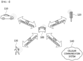
- FIG. 1 is a conceptual diagram illustrating V2X communication scenarios.
- the V2X communications may include Vehicle-to-Vehicle (V2V) communications, Vehicle-to-Infrastructure (V2I) communications, Vehicle-to-Pedestrian (V2P) communications, Vehicle-to-Network (V2N) communications, and the like.
- V2V Vehicle-to-Vehicle
- V2I Vehicle-to-Infrastructure
- V2P Vehicle-to-Pedestrian
- V2N Vehicle-to-Network
- the V2X communications may be supported by a cellular communication system (e.g., a cellular communication system 140), and the V2X communications supported by the cellular communication system 140 may be referred to as "Cellular-V2X (C-V2X) communications.”
- the cellular communication system 140 may include the 4G communication system (e.g., LTE communication system or LTE-A communication system), the 5G communication system (e.g., NR communication system), and the like.
- the V2V communications may include communications between a first vehicle 100 (e.g., a communication node located in the vehicle 100) and a second vehicle 110 (e.g., a communication node located in the vehicle 110).
- Various driving information such as velocity, heading, time, position, and the like may be exchanged between the vehicles 100 and 110 through the V2V communications.
- autonomous driving e.g., platooning
- the V2V communications supported in the cellular communication system 140 may be performed based on "sidelink" communication technologies (e.g., ProSe and D2D communication technologies, and the like). In this case, the communications between the vehicles 100 and 110 may be performed using at least one sidelink channel established between the vehicles 100 and 110.
- the V2I communications may include communications between the first vehicle 100 (e.g., the communication node located in the vehicle 100) and an infrastructure (e.g., road side unit (RSU)) 120 located on a roadside.
- the infrastructure 120 may also include a traffic light or a street light which is located on the roadside.
- the communications may be performed between the communication node located in the first vehicle 100 and a communication node located in a traffic light. Traffic information, driving information, and the like may be exchanged between the first vehicle 100 and the infrastructure 120 through the V2I communications.
- the V2I communications supported in the cellular communication system 140 may also be performed based on sidelink communication technologies (e.g., ProSe and D2D communication technologies, and the like). In this case, the communications between the vehicle 100 and the infrastructure 120 may be performed using at least one sidelink channel established between the vehicle 100 and the infrastructure 120.
- the V2P communications may include communications between the first vehicle 100 (e.g., the communication node located in the vehicle 100) and a person 130 (e.g., a communication node carried by the person 130).
- the driving information of the first vehicle 100 and movement information of the person 130 such as velocity, heading, time, position, and the like may be exchanged between the vehicle 100 and the person 130 through the V2P communications.
- the communication node located in the vehicle 100 or the communication node carried by the person 130 may generate an alarm indicating a danger by judging a dangerous situation based on the obtained driving information and movement information.
- the V2P communications supported in the cellular communication system 140 may be performed based on sidelink communication technologies (e.g., ProSe and D2D communication technologies, and the like). In this case, the communications between the communication node located in the vehicle 100 and the communication node carried by the person 130 may be performed using at least one sidelink channel established between the communication nodes.
- the V2N communications may be communications between the first vehicle 100 (e.g., the communication node located in the vehicle 100) and a server connected through the cellular communication system 140.
- the V2N communications may be performed based on the 4G communication technology (e.g., LTE or LTE-A) or the 5G communication technology (e.g., NR).
- the V2N communications may be performed based on a Wireless Access in Vehicular Environments (WAVE) communication technology or a Wireless Local Area Network (WLAN) communication technology which is defined in Institute of Electrical and Electronics Engineers (IEEE) 802.11, or a Wireless Personal Area Network (WPAN) communication technology defined in IEEE 802.15.
- WAVE Wireless Access in Vehicular Environments
- WLAN Wireless Local Area Network
- IEEE 802.11 Institute of Electrical and Electronics Engineers
- WPAN Wireless Personal Area Network
- the cellular communication system 140 supporting the V2X communications may be configured as follows.
- FIG. 2 is a conceptual diagram illustrating an exemplary embodiment of a cellular communication system.
- a cellular communication system may include an access network, a core network, and the like.
- the access network may include a base station 210, a relay 220, User Equipments (UEs) 231 through 236, and the like.
- the UEs 231 through 236 may include communication nodes located in the vehicles 100 and 110 of FIG. 1 , the communication node located in the infrastructure 120 of FIG. 1 , the communication node carried by the person 130 of FIG. 1 , and the like.
- the core network may include a serving gateway (S-GW) 250, a packet data network (PDN) gateway (P-GW) 260, a mobility management entity (MME) 270, and the like.
- S-GW serving gateway
- PDN packet data network gateway
- MME mobility management entity
- the core network may include a user plane function (UPF) 250, a session management function (SMF) 260, an access and mobility management function (AMF) 270, and the like.
- the core network constituted by the S-GW 250, the P-GW 260, and the MME 270 may support the 5G communication technology as well as the 4G communication technology
- the core network constituted by the UPF 250, the SMF 260, and the AMF 270 may support the 4G communication technology as well as the 5G communication technology.
- the core network may be divided into a plurality of logical network slices.
- a network slice supporting V2X communications e.g., a V2V network slice, a V2I network slice, a V2P network slice, a V2N network slice, etc.
- V2X communications may be supported through the V2X network slice configured in the core network.
- the communication nodes comprising the cellular communication system may perform communications by using at least one communication technology among a code division multiple access (CDMA) technology, a time division multiple access (TDMA) technology, a frequency division multiple access (FDMA) technology, an orthogonal frequency division multiplexing (OFDM) technology, a filtered OFDM technology, an orthogonal frequency division multiple access (OFDMA) technology, a single carrier FDMA (SC-FDMA) technology, a non-orthogonal multiple access (NOMA) technology, a generalized frequency division multiplexing (GFDM) technology, a filter bank multi-carrier (FBMC) technology, a universal filtered multi-carrier (UFMC) technology, and a space division multiple access (SDMA) technology.
- CDMA code division multiple access
- TDMA time division multiple access
- FDMA frequency division multiple access
- OFDM orthogonal frequency division multiplexing
- OFDM orthogonal frequency division multiplexing
- a filtered OFDM technology an orthogonal frequency division multiple access
- the communication nodes comprising the cellular communication system may be configured as follows.
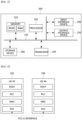
- FIG. 3 is a conceptual diagram illustrating an exemplary embodiment of a communication node constituting a cellular communication system.
- a communication node 300 may comprise at least one processor 310, a memory 320, and a transceiver 330 connected to a network for performing communications. Also, the communication node 300 may further comprise an input interface device 340, an output interface device 350, a storage device 360, and the like. Each component included in the communication node 300 may communicate with each other as connected through a bus 370.
- each of the components included in the communication node 300 may be connected to the processor 310 via a separate interface or a separate bus rather than the common bus 370.
- the processor 310 may be connected to at least one of the memory 320, the transceiver 330, the input interface device 340, the output interface device 350, and the storage device 360 via a dedicated interface.
- the processor 310 may execute at least one instruction stored in at least one of the memory 320 and the storage device 360.
- the processor 310 may refer to a central processing unit (CPU), a graphics processing unit (GPU), or a dedicated processor on which methods in accordance with embodiments of the present disclosure are performed.
- Each of the memory 320 and the storage device 360 may include at least one of a volatile storage medium and a non-volatile storage medium.
- the memory 320 may comprise at least one of read-only memory (ROM) and random access memory (RAM).
- the base station 210 may form a macro cell or a small cell, and may be connected to the core network via an ideal backhaul or a non-ideal backhaul.
- the base station 210 may transmit signals received from the core network to the UEs 231 through 236 and the relay 220, and may transmit signals received from the UEs 231 through 236 and the relay 220 to the core network.
- the LTEs 231, 232, 234, 235 and 236 may belong to cell coverage of the base station 210.
- the UEs 231, 232, 234, 235 and 236 may be connected to the base station 210 by performing a connection establishment procedure with the base station 210.
- the UEs 231, 232, 234, 235 and 236 may communicate with the base station 210 after being connected to the base station 210.
- the relay 220 may be connected to the base station 210 and may relay communications between the base station 210 and the UEs 233 and 234. That is, the relay 220 may transmit signals received from the base station 210 to the UEs 233 and 234, and may transmit signals received from the LTEs 233 and 234 to the base station 210.
- the LTE 234 may belong to both of the cell coverage of the base station 210 and the cell coverage of the relay 220, and the LTE 233 may belong to the cell coverage of the relay 220. That is, the UE 233 may be located outside the cell coverage of the base station 210.
- the UEs 233 and 234 may be connected to the relay 220 by performing a connection establishment procedure with the relay 220.
- the UEs 233 and 234 may communicate with the relay 220 after being connected to the relay 220.
- the base station 210 and the relay 220 may support multiple-input, multiple-output (MIMO) technologies (e.g., single user (SU)-MIMO, multi-user (MU)-MIMO, massive MIMO, etc.), coordinated multipoint (CoMP) communication technologies, carrier aggregation (CA) communication technologies, unlicensed band communication technologies (e.g., Licensed Assisted Access (LAA), enhanced LAA (eLAA), etc.), sidelink communication technologies (e.g., ProSe communication technology, D2D communication technology), or the like.
- MIMO multiple-input, multiple-output
- CA carrier aggregation
- LAA Licensed Assisted Access
- eLAA enhanced LAA
- sidelink communication technologies e.g., ProSe communication technology, D2D communication technology
- the UEs 231, 232, 235 and 236 may perform operations corresponding to the base station 210 and operations supported by the base station 210.
- the LTEs 233 and 234 may perform operations corresponding to the
- the base station 210 may be referred to as a Node B (NB), an evolved Node B (eNB), a base transceiver station (BTS), a radio remote head (RRH), a transmission reception point (TRP), a radio unit (RU), a roadside unit (RSU), a radio transceiver, an access point, an access node, or the like.
- the relay 220 may be referred to as a small base station, a relay node, or the like.
- Each of the UEs 231 through 236 may be referred to as a terminal, an access terminal, a mobile terminal, a station, a subscriber station, a mobile station, a portable subscriber station, a node, a device, an on-broad unit (OBU), or the like.
- a terminal an access terminal
- a mobile terminal a station
- a subscriber station a mobile station
- a portable subscriber station a node
- a device an on-broad unit (OBU), or the like.
- OBU on-broad unit
- the communications between the UEs 235 and 236 may be performed based on the sidelink communication technique.
- the sidelink communications may be performed based on a one-to-one scheme or a one-to-many scheme.
- V2V communications are performed using the sidelink communication technique
- the UE 235 may be the communication node located in the first vehicle 100 of FIG. 1 and the UE 236 may be the communication node located in the second vehicle 110 of FIG. 1 .
- V2I communications are performed using the sidelink communication technique
- the UE 235 may be the communication node located in first vehicle 100 of FIG. 1 and the UE 236 may be the communication node located in the infrastructure 120 of FIG. 1 .
- V2P communications are performed using the sidelink communication technique
- the UE 235 may be the communication node located in first vehicle 100 of FIG. 1 and the UE 236 may be the communication node carried by the person 130 of FIG. 1 .
- the scenarios to which the sidelink communications are applied may be classified as shown below in Table 1 according to the positions of the UEs (e.g., the UEs 235 and 236) participating in the sidelink communications.
- the scenario for the sidelink communications between the LTEs 235 and 236 shown in FIG. 2 may be a sidelink communication scenario C.
- a user plane protocol stack of the UEs (e.g., the UEs 235 and 236) performing sidelink communications may be configured as follows.
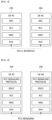
- FIG. 4 is a block diagram illustrating an exemplary embodiment of a user plane protocol stack of a LTE performing sidelink communication.
- a left UE may be the UE 235 shown in FIG. 2 and a right UE may be the UE 236 shown in FIG. 2 .
- the scenario for the sidelink communications between the UEs 235 and 236 may be one of the sidelink communication scenarios A through D of Table 1.
- the user plane protocol stack of each of the UEs 235 and 236 may comprise a physical (PHY) layer, a medium access control (MAC) layer, a radio link control (RLC) layer, and a packet data convergence protocol (PDCP) layer.
- PHY physical
- MAC medium access control
- RLC radio link control
- PDCP packet data convergence protocol
- the sidelink communications between the UEs 235 and 236 may be performed using a PC5 interface (e.g., PC5-U interface).
- a layer-2 identifier (e.g., a source layer-2 ID, a destination layer-2 ID) may be used for the sidelink communications, and the layer 2-ID may be an ID configured for the V2X communications (e.g., V2X service).
- HARQ hybrid automatic repeat request
- RLC AM RLC acknowledged mode
- RLC UM RLC unacknowledged mode
- a control plane protocol stack of the UEs e.g., the UEs 235 and 236) performing sidelink communications may be configured as follows.
- FIG. 5 is a block diagram illustrating a first exemplary embodiment of a control plane protocol stack of a LTE performing sidelink communication
- FIG. 6 is a block diagram illustrating a second exemplary embodiment of a control plane protocol stack of a LTE performing sidelink communication.
- a left UE may be the LTE 235 shown in FIG. 2 and a right UE may be the UE 236 shown in FIG. 2 .
- the scenario for the sidelink communications between the UEs 235 and 236 may be one of the sidelink communication scenarios A through D of Table 1.
- the control plane protocol stack illustrated in FIG. 5 may be a control plane protocol stack for transmission and reception of broadcast information (e.g., Physical Sidelink Broadcast Channel (PSBCH)).
- PSBCH Physical Sidelink Broadcast Channel
- the control plane protocol stack shown in FIG. 5 may include a PHY layer, a MAC layer, an RLC layer, and a radio resource control (RRC) layer.
- the sidelink communications between the UEs 235 and 236 may be performed using a PC5 interface (e.g., PC5-C interface).
- the control plane protocol stack shown in FIG. 6 may be a control plane protocol stack for one-to-one sidelink communication.
- the control plane protocol stack shown in FIG. 6 may include a PHY layer, a MAC layer, an RLC layer, a PDCP layer, and a PC5 signaling protocol layer.
- channels used in the sidelink communications between the UEs 235 and 236 may include a Physical Sidelink Shared Channel (PSSCH), a Physical Sidelink Control Channel (PSCCH), a Physical Sidelink Discovery Channel (PSDCH), and a Physical Sidelink Broadcast Channel (PSBCH).
- PSSCH may be used for transmitting and receiving sidelink data and may be configured in the UE (e.g., UE 235 or 236) by a higher layer signaling.
- the PSCCH may be used for transmitting and receiving sidelink control information (SCI) and may also be configured in the UE (e.g., UE 235 or 236) by a higher layer signaling.
- SCI sidelink control information
- the PSDCH may be used for a discovery procedure.
- a discovery signal may be transmitted over the PSDCH.
- the PSBCH may be used for transmitting and receiving broadcast information (e.g., system information).
- a demodulation reference signal (DM-RS), a synchronization signal, or the like may be used in the sidelink communications between the UEs 235 and 236.
- the synchronization signal may include a primary sidelink synchronization signal (PSSS) and a secondary sidelink synchronization signal (SSSS).
- a sidelink transmission mode may be classified into sidelink TMs 1 to 4 as shown below in Table 2.
- Sidelink TM Description 1 Transmission using resources scheduled by base station 2 UE autonomous transmission without scheduling of base station 3
- each of the UEs 235 and 236 may perform sidelink communications using a resource pool configured by the base station 210.
- the resource pool may be configured for each of the sidelink control information and the sidelink data.
- the resource pool for the sidelink control information may be configured based on an RRC signaling procedure (e.g., a dedicated RRC signaling procedure, a broadcast RRC signaling procedure).
- the resource pool used for reception of the sidelink control information may be configured by a broadcast RRC signaling procedure.
- the resource pool used for transmission of the sidelink control information may be configured by a dedicated RRC signaling procedure.
- the sidelink control information may be transmitted through resources scheduled by the base station 210 within the resource pool configured by the dedicated RRC signaling procedure.
- the resource pool used for transmission of the sidelink control information may be configured by a dedicated RRC signaling procedure or a broadcast RRC signaling procedure.
- the sidelink control information may be transmitted through resources selected autonomously by the LTE (e.g., LTE 235 or 236) within the resource pool configured by the dedicated RRC signaling procedure or the broadcast RRC signaling procedure.
- the resource pool for transmitting and receiving sidelink data may not be configured.
- the sidelink data may be transmitted and received through resources scheduled by the base station 210.
- the resource pool for transmitting and receiving sidelink data may be configured by a dedicated RRC signaling procedure or a broadcast RRC signaling procedure.
- the sidelink data may be transmitted and received through resources selected autonomously by the UE (e.g., UE 235 or 236) within the resource pool configured by the dedicated RRC signaling procedure or the broadcast RRC signaling procedure.
- a corresponding second communication node may perform a method (e.g., reception or transmission of the signal) corresponding to the method performed at the first communication node. That is, when an operation of a UE #1 (e.g., vehicle #1) is described, a UE #2 (e.g., vehicle #2) corresponding thereto may perform an operation corresponding to the operation of the UE #1. Conversely, when an operation of the UE #2 is described, the corresponding LTE #1 may perform an operation corresponding to the operation of the UE #2.
- an operation of a vehicle may be an operation of a communication node located in the vehicle.
- signaling may be one or a combination of two or more of higher layer signaling, MAC signaling, and physical (PHY) signaling.
- a message used for higher layer signaling may be referred to as a 'higher layer message' or 'higher layer signaling message'.
- a message used for MAC signaling may be referred to as a 'MAC message' or 'MAC signaling message'.
- a message used for PHY signaling may be referred to as a 'PHY message' or 'PHY signaling message'.
- the higher layer signaling may refer to an operation of transmitting and receiving system information (e.g., master information block (MIB), system information block (SIB)) and/or an RRC message.
- MIB master information block
- SIB system information block
- the MAC signaling may refer to an operation of transmitting and receiving a MAC control element (CE).
- the PHY signaling may refer to an operation of transmitting and receiving control information (e.g., downlink control information (DCI), uplink control information (UCI), or SCI).
- DCI downlink control information
- UCI uplink control information
- SCI SCI
- a sidelink signal may be a synchronization signal and a reference signal used for sidelink communication.
- the synchronization signal may be a synchronization signal/physical broadcast channel (SS/PBCH) block, sidelink synchronization signal (SLSS), primary sidelink synchronization signal (PSSS), secondary sidelink synchronization signal (SSSS), or the like.
- the reference signal may be a channel state information-reference signal (CSI-RS), DM-RS, phase tracking-reference signal (PT-RS), cell-specific reference signal (CRS), sounding reference signal (SRS), discovery reference signal (DRS), or the like.
- a sidelink channel may be a PSSCH, PSCCH, PSDCH, PSBCH, physical sidelink feedback channel (PSFCH), or the like.
- a sidelink channel may refer to a sidelink channel including a sidelink signal mapped to specific resources in the corresponding sidelink channel.
- the sidelink communication may support a broadcast service, a multicast service, a groupcast service, and a unicast service.
- the sidelink communication may be performed based on a single-SCI scheme or a multi-SCI scheme.
- data transmission e.g., sidelink data transmission, sidelink-shared channel (SL-SCH) transmission
- SL-SCH sidelink-shared channel
- data transmission may be performed based on one SCI (e.g., 1st-stage SCI).
- the multi-SCI scheme data transmission may be performed using two SCIs (e.g., 1 st-stage SCI and 2nd-stage SCI).
- the SCI(s) may be transmitted on a PSCCH and/or a PSSCH.
- the single-SCI scheme the SCI (e.g., 1st-stage SCI) may be transmitted on a PSCCH.
- the 1st-stage SCI may be transmitted on a PSCCH, and the 2nd-stage SCI may be transmitted on the PSCCH or a PSSCH.
- the 1st-stage SCI may be referred to as 'first-stage SCI', and the 2nd-stage SCI may be referred to as 'second-stage SCI'.
- a format of the first-stage SCI may include a SCI format 1-A
- a format of the second-stage SCI may include a SCI format 2-A and a SCI format 2-B.
- the 1st-stage SCI may include or more information elements among priority information, frequency resource assignment information, time resource assignment information, resource reservation period information, demodulation reference signal (DMRS) pattern information, 2nd-stage SCI format information, a beta_offset indicator, the number of DMRS ports, and modulation and coding scheme (MCS) information.
- the 2nd-stage SCI may include one or more information elements among a HARQ processor identifier (ID), a redundancy version (RV), a source ID, a destination ID, CSI request information, a zone ID, and communication range requirements.
- a transmitting terminal may perform SL communication with a receiving terminal.
- the SL communication between the transmitting terminal and the receiving terminal may be performed in a unicast scheme.
- the transmitting terminal may refer to a terminal that transmits data (e.g., SL data) through a sidelink. That is, the transmitting terminal may refer to a source terminal.
- the receiving terminal may refer to a terminal that receives the SL data through the sidelink. That is, the receiving terminal may refer to a destination terminal.
- relay communication e.g., SL relay communication
- a connection between the transmitting terminal and a relay terminal may be configured, and a connection between the receiving terminal and the relay terminal may be configured.
- SL relay communication may be performed.
- a method of configuring connections between the terminals may be performed as follows.
- FIG. 7 is a sequence chart illustrating a first exemplary embodiment of a connection configuration method for SL relay communication.
- a communication system may include a transmitting terminal, a receiving terminal, and a relay terminal.
- Each of the transmitting terminal, receiving terminal, and relay terminal may be configured identically or similarly to the communication node 300 shown in FIG. 3 .
- the transmitting terminal, receiving terminal, and relay terminal may support the protocol stack(s) shown in FIGS. 4 to 6 .
- the transmitting terminal may perform SL communication with the receiving terminal (S701).
- the SL communication may be performed in a unicast scheme.
- the SL communication may be performed using resource(s) allocated according to a mode 1 or resource(s) selected according to a mode 2.
- the mode 1 may be the SL TM #1 or #3 defined in Table 2
- the mode 2 may be the SL TM #2 or #4 defined in Table 2.
- the transmitting terminal may determine whether SL relay communication is required (S702). That is, the transmitting terminal may determine whether SL relay communication needs to be performed instead of the SL communication.
- the transmitting terminal may perform the step S702 by itself regardless of configuration of a base station.
- the step S702 may be performed according to configuration of a base station (e.g., the base station to which the transmitting terminal is connected).
- the base station may use at least one of system information, RRC message, MAC control element (CE), and/or DCI to transmit an enable/disable indicator of SL relay communication the terminal (e.g., transmitting terminal and/or receiving terminal).
- the transmitting terminal may receive the enable/disable indicator of SL relay communication from the base station.
- the indicator indicates to disable SL relay communication
- the transmitting terminal may not perform the step S702 (or steps S702 to S709).
- the transmitting terminal may perform the step S702 (or S702 to S709).
- the transmitting terminal may determine that SL relay communication is required when one or more conditions defined in Table 3 below are satisfied.
- negative acknowledgment NACK
- p may be a natural number.
- Condition 1 When the number of NACKs received from the receiving terminal is p or more
- Condition 2 When a channel quality (e.g., link quality) between the transmitting terminal and the receiving terminal is equal to or less than a reference value (e.g., RSRP, RSRQ, RSSI, SINR)
- a reference value e.g., RSRP, RSRQ, RSSI, SINR
- the base station may use at least one of system information, RRC message, MAC CE, or DCI to transmit to the terminal (e.g., transmitting terminal and/or receiving terminal) information (e.g., p and/or reference value) required to determine whether the condition(s) defined in Table 3 are satisfied.
- the transmitting terminal may determine whether the condition(s) defined in Table 3 are satisfied based on the information received from the base station. When it is determined that SL relay communication is not required, the transmitting terminal may perform the SL communication with the receiving terminal without SL relaying (S701). When it is determined that SL relay communication is required, the transmitting terminal may perform the following steps. That is, the transmitting terminal may discovery a relay terminal (S703).
- the transmitting terminal may transmit information indicating to perform a connection configuration operation for SL relay communication to the base station by using at least one of an RRC message, MAC CE, or control information (e.g., UCI).
- the base station may determine that a connection configuration operation for SL relay communication is to be performed based on the information received from the transmitting terminal.
- the information indicating to perform the connection configuration operation for SL relay communication may be transmitted to the base station after the step S702 or after the step S703.
- the information may be transmitted to the base station together with information (e.g., identifier) of the relay terminal discovered in the step S703. In this case, the base station may identify the information of the relay terminal supporting SL relay communication.
- the transmitting terminal may receive signal(s) and/or channel(s) from neighboring terminal(s), and may determine one of the neighboring terminal(s) as the relay terminal based on a measurement result of the signal(s) and/or channel(s).
- the signal may be a reference signal, synchronization signal, and/or discovery signal
- the channel may be a PSCCH, PSSCH, PSFCH, PSBCH, and/or PSDCH.
- the transmitting terminal may determine a neighbor terminal having a measurement result equal to or greater than a threshold value as the relay terminal.
- the threshold value may be a threshold value of a reference signal received power (RSRP), reference signal received quality (RSRQ), received signal strength indicator (RSSI), or signal to interference plus noise ratio (SINR).
- RSRP reference signal received power
- RSSI received signal strength indicator
- SINR signal to interference plus noise ratio
- the threshold value may be defined in technical specifications.
- the base station may inform the threshold value to the terminal (e.g., transmitting terminal and/or receiving terminal) by using system information, RRC message, MAC CE, or DCI.
- the transmitting terminal may configure a connection with the discovered relay terminal (S704).
- the connection between the transmitting terminal and the relay terminal may be a PC5 connection.
- SL communication between the transmitting terminal and the relay terminal may be performed in a unicast scheme.
- the transmitting terminal may transmit its own information (e.g., capability information or identifier) to the relay terminal, and the relay terminal may transmit its own information (e.g., capability information, or identifier) to the transmitting terminal.
- the transmitting terminal may identify the information of the relay terminal, and the relay terminal may identify the information of the transmitting terminal.
- the identifier of the relay terminal may be a layer 2 (L2) identifier, ProSe UE ID, and/or ProSe application code. Each of the ProSe UE ID and ProSe application code may correspond to the L2 identifier.
- the ProSe UE ID and/or the ProSe application code may be identifiable in a higher layer of a communication node (e.g., transmitting terminal, receiving terminal, and relay terminal).
- a transmission procedure of a discovery message (e.g., discovery signal) may be performed in a higher layer and/or a lower layer (e.g., PDCP layer, RRC layer, or MAC layer).
- the identifier of the relay terminal may be at least one of an L2 identifier, ProSe UE ID, and ProSe application code.
- a combination of L2 identifier and ProSe UE ID or a combination of L2 identifier and ProSe application code may be used as the identifier of the relay terminal.
- the transmitting terminal may transmit a first message to the receiving terminal (S705).
- the first message may be transmitted to support connection configuration between the receiving terminal and the relay terminal.
- the first message may be an RRC reconfiguration sidelink message (i.e., RRC ReconfigurationSidelink message).
- the first message may include one or more information elements defined in Table 4 below. That is, the first message may include connection configuration information for the SL relay communication.
- the first message may be SCI (e.g., first-stage SCI and/or second-stage SCI). In this case, one or more information elements defined in Table 4 may be included in the SCI transmitted from the transmitting terminal to the receiving terminal.
- relay link indicator may indicate that SL relay communication is required, that SL communication is relayed through the relay terminal, and/or that connection configuration between the transmitting terminal and the relay terminal has been completed.
- Hyper frame number (HFN) HFN may indicate a number identifying data transmitted last to the receiving terminal after the connection configuration operation between the transmitting terminal and the relay terminal is determined to be performed, or after the connection configuration between the transmitting terminal and the relay terminal has been complected.
- the identifier of the relay terminal may be referred to as sl-RelayUE-Identity.
- the relay link indicator may be configured in ENUMERATED or BOOLEAN type.
- the HFN may be used to determine whether data is lost in the SL relay communication between the transmitting terminal and the receiving terminal.
- the HFN may be delivered to the receiving terminal through another message instead of the first message.
- the transmitting terminal may receive a second message from the receiving terminal after transmitting the first message, and then transmit a third message including the HFN to the receiving terminal.
- the receiving terminal may identify the HFN by receiving the third message from the transmitting terminal.
- the second message may be an RRC reconfiguration complete sidelink message (i.e., RRC ReconfigurationCompleteSidelink message), an RRC reconfiguration complete message (i.e., RRCReconfigurationComplete message), or SCI
- the third message may be an RRC message.
- the third message may be SCI.
- the receiving terminal may receive the first message from the transmitting terminal, and may identify information element(s) included in the first message (e.g., information element(s) defined in Table 4). Based on the relay link indicator included in the first message, the receiving terminal may determine that the SL relay communication is required, that the SL communication is relayed through the relay terminal, and/or that the connection configuration between the transmitting terminal and the relay terminal has been completed. The receiving terminal may identify the relay terminal supporting the SL relay communication based on the information of the relay terminal included in the first message. The receiving terminal may identify the number identifying the data transmitted last by the transmitting terminal based on the HFN included in the first message. After the connection configuration between the receiving terminal and the relay terminal has been completed, the receiving terminal may identify whether data is lost in the SL relay communication through the relay terminal based on the HFN.
- information element(s) included in the first message e.g., information element(s) defined in Table 4
- the receiving terminal may determine that the SL relay communication is required, that the SL communication is relay
- the receiving terminal may discover the relay terminal indicated by the first message (S706). For example, the receiving terminal may identify identifier(s) of neighboring terminal(s) by receiving signal(s) and/or channel(s) from the neighboring terminal(s), and determine whether the identified identifier is the same as the identifier included in the first message.
- the signal may be a reference signal, synchronization signal, and/or discovery signal
- the channel may be a PSCCH, PSSCH, PSFCH, PSBCH, and/or PSDCH.
- the receiving terminal may determine a neighbor terminal having the identified identifier as the relay terminal.
- an L2 layer and/or higher layer of the receiving terminal may identify the identifier (e.g., L2 identifier, ProSe LTE ID, and/or ProSe application code) of the neighboring terminal, and may determine whether the identified identifier is the same as the identifier included in the first message (i.e., the identifier of the relay terminal).
- the identifier e.g., L2 identifier, ProSe LTE ID, and/or ProSe application code
- the receiving terminal may configure a connection with the discovered relay terminal (S707). That is, the receiving terminal and the transmitting terminal may be connected to the same relay terminal.
- the connection between the receiving terminal and the relay terminal may be a PC5 connection.
- SL communication between the receiving terminal and the relay terminal may be performed in a unicast scheme.
- the receiving terminal may transmit its own information (e.g., capability information, identifier) to the relay terminal, and the relay terminal may transmit its own information (e.g., capability information, identifier) to the receiving terminal. Accordingly, the receiving terminal may identify the information of the relay terminal, and the relay terminal may identify the information of the receiving terminal.
- the receiving terminal may transmit the second message indicating that the connection configuration between the receiving terminal and the relay terminal has been completed to the transmitting terminal (S708).
- the second message may indicate that the SL relay communication is possible.
- the second message may be an RRC reconfiguration complete sidelink message (i.e., RRCReconfigurationCompleteSidelink message) or an RRC reconfiguration complete message (i.e., RRCReconfigurationComplete message).
- the second message may be SCI (e.g., first-stage SCI and/or second-stage SCI).
- the second message may include one or more information elements defined in Table 4.
- the information of the relay terminal included in the second message may indicate the relay terminal that has completed the connection configuration with the receiving terminal.
- the relay link indicator included in the second message may indicate that the SL relay communication is possible and/or that the connection configuration between the receiving terminal and the relay terminal has been completed.
- the relay link indicator may be configured in ENUMERATED or BOOLEAN type.
- the HFN included in the second message may indicate a number identifying data last transmitted by the transmitting terminal and/or a number identifying data last received by the receiving terminal.
- the transmitting terminal may transmit information indicating that the connection configuration between the transmitting terminal and the receiving terminal has been completed to the base station by using at least one of a higher layer message, MAC CE, or control information (e.g., UCI).
- a higher layer message e.g., MAC CE, or control information (e.g., UCI).
- control information e.g., UCI.
- the information indicating that the connection configuration between the transmitting terminal and the receiving terminal has been completed is transmitted after the step S708, the information may be transmitted to the base station together with the information (e.g., capability information, identifier) of the relay terminal having completed the connection configuration with the transmitting terminal.
- the base station may identify the information of the relay terminal connected to the transmitting terminal.
- the receiving terminal may transmit the second message indicating that connection configuration between the receiving terminal and the relay terminal has failed to the transmitting terminal (S708).
- the second message may indicate that the SL relay communication is impossible.
- the second message may be an RRC reconfiguration failure sidelink message (i.e., RRCReconfigurationFailureSidelink message) or an RRC reconfiguration failure message (i.e., RRCReconfigurationFailure message).
- the second message may be SCI (e.g., first-stage SCI and/or second-stage SCI).
- the second message may include one or more information elements defined in Table 4.
- the information of the relay terminal included in the second message may indicate the relay terminal having failed the connection configuration with the receiving terminal.
- the relay link indicator included in the second message may indicate that the SL relay communication is impossible and/or that the connection configuration between the receiving terminal and the relay terminal has failed.
- the relay link indicator may be configured in ENUMERATED or BOOLEAN type.
- the transmitting terminal may perform a monitoring operation for receiving the second message after transmitting the first message. If the second message is not received within a preset time or if the second message received from the receiving terminal indicates that the connection configuration between the receiving terminal and the relay terminal has failed, the transmitting terminal may determine that the connection configuration between the receiving terminal and the relay terminal has failed. In this case, the transmitting terminal may not perform the SL relay communication. That is, the transmitting terminal may perform the SL communication with the receiving terminal without the relay terminal. In addition, the transmitting terminal may transmit a message indicating to release the connection configuration between the transmitting terminal and the relay terminal to the relay terminal. Upon receiving the message indicating to release the connection configuration between the transmitting terminal and the relay terminal, the relay terminal may release the connection configuration between the relay terminal and the transmitting terminal.
- the transmitting terminal may determine that the connection configuration between the receiving terminal and the relay terminal has been completed. In this case, the transmitting terminal may perform the SL relay communication with the receiving terminal (S709). That is, the transmitting terminal may perform SL communication with the receiving terminal through relaying of the relay terminal. For example, the transmitting terminal may transmit SCI and/or data for the receiving terminal to the relay terminal, the relay terminal may transmit the SCI and/or data received from the transmitting terminal to the receiving terminal, and the receiving terminal may receive the SCI and/or data from the relay terminal.
- the receiving terminal may transmit HARQ-ACK for the data to the relay terminal, the relay terminal may transmit the HARQ-ACK received from the receiving terminal to the transmitting terminal, and the transmitting terminal may receive the HARQ-ACK from the relay terminal.
- the transmitting terminal may release the connection configuration (e.g., SL configuration) between the transmitting terminal and the receiving terminal.
- the receiving terminal may release the connection configuration (e.g., SL configuration) between the receiving terminal and the transmitting terminal.
- the exemplary embodiments of the present disclosure may be implemented as program instructions executable by a variety of computers and recorded on a computer readable medium.
- the computer readable medium may include a program instruction, a data file, a data structure, or a combination thereof.
- the program instructions recorded on the computer readable medium may be designed and configured specifically for the present disclosure or can be publicly known and available to those who are skilled in the field of computer software.
- Examples of the computer readable medium may include a hardware device such as ROM, RAM, and flash memory, which are specifically configured to store and execute the program instructions.
- Examples of the program instructions include machine codes made by, for example, a compiler, as well as high-level language codes executable by a computer, using an interpreter.
- the above exemplary hardware device can be configured to operate as at least one software module in order to perform the embodiments of the present disclosure, and vice versa.
Landscapes
- Engineering & Computer Science (AREA)
- Computer Networks & Wireless Communication (AREA)
- Signal Processing (AREA)
- Mobile Radio Communication Systems (AREA)
- Communication Control (AREA)
Applications Claiming Priority (2)
| Application Number | Priority Date | Filing Date | Title |
|---|---|---|---|
| US202063092595P | 2020-10-16 | 2020-10-16 | |
| PCT/KR2021/013921 WO2022080782A1 (ko) | 2020-10-16 | 2021-10-08 | 사이드링크에서 릴레이 통신을 위한 방법 및 장치 |
Publications (1)
| Publication Number | Publication Date |
|---|---|
| EP4231764A1 true EP4231764A1 (en) | 2023-08-23 |
Family
ID=81452032
Family Applications (1)
| Application Number | Title | Priority Date | Filing Date |
|---|---|---|---|
| EP21880429.2A Pending EP4231764A1 (en) | 2020-10-16 | 2021-10-08 | Method and device for relay communication on sidelink |
Country Status (3)
| Country | Link |
|---|---|
| EP (1) | EP4231764A1 (zh) |
| KR (1) | KR20220050782A (zh) |
| CN (1) | CN116671243A (zh) |
Cited By (1)
| Publication number | Priority date | Publication date | Assignee | Title |
|---|---|---|---|---|
| WO2024022044A1 (zh) * | 2022-07-29 | 2024-02-01 | 华为技术有限公司 | 一种通信方法、通信装置及计算机可读存储介质 |
Families Citing this family (1)
| Publication number | Priority date | Publication date | Assignee | Title |
|---|---|---|---|---|
| WO2024029921A1 (ko) * | 2022-08-02 | 2024-02-08 | 엘지전자 주식회사 | 무선통신시스템에서 ue-to-ue relay 에서 id 설정 등에 관련된 릴레이 ue의 동작 방법 |
-
2021
- 2021-10-08 EP EP21880429.2A patent/EP4231764A1/en active Pending
- 2021-10-08 CN CN202180070777.3A patent/CN116671243A/zh active Pending
- 2021-10-08 KR KR1020210133801A patent/KR20220050782A/ko unknown
Cited By (1)
| Publication number | Priority date | Publication date | Assignee | Title |
|---|---|---|---|---|
| WO2024022044A1 (zh) * | 2022-07-29 | 2024-02-01 | 华为技术有限公司 | 一种通信方法、通信装置及计算机可读存储介质 |
Also Published As
| Publication number | Publication date |
|---|---|
| CN116671243A (zh) | 2023-08-29 |
| KR20220050782A (ko) | 2022-04-25 |
Similar Documents
| Publication | Publication Date | Title |
|---|---|---|
| EP3910806A1 (en) | Method and device for managing beam in sidelink communication | |
| EP3998727A1 (en) | Method and apparatus for transmitting and receiving harq response in communication system supporting sidelink communication | |
| US20220295517A1 (en) | Method and apparatus for transmitting and receiving harq responses in wireless communication system supporting sidelink communication | |
| US20230269759A1 (en) | Communication method based on inter-ue coordination information in sidelink | |
| US20230269756A1 (en) | Method and apparatus for transmitting sci in sidelink communication | |
| EP4231764A1 (en) | Method and device for relay communication on sidelink | |
| US20220303956A1 (en) | Method and device for transmitting and receiving inter-ue coordination information in sidelink communication | |
| US20230199801A1 (en) | Method and apparatus for transmitting and receiving sidelink data in communication system | |
| EP4240097A1 (en) | Method and device for link recovery in sidelink relay communication | |
| EP4231737A1 (en) | Method and device for paging in sidelink communication | |
| EP4037216A1 (en) | Method and apparatus for transmitting and receiving harq response in communication system | |
| US20230379989A1 (en) | Method and device for relay communication on sidelink | |
| US20230269812A1 (en) | Method and device for link recovery in sidelink relay communication | |
| EP4240096A1 (en) | Method and device for relay communication in sidelink | |
| US20230379990A1 (en) | Method and device for relay communication in sidelink | |
| EP4277384A1 (en) | Method and device for resource selection based on mode 2 in sidelink communication | |
| EP4224962A1 (en) | Communication method based on inter-ue coordination information in sidelink | |
| US20230422217A1 (en) | Method and device for resource sensing and selection in sidelink communication supporting drx operation | |
| US20230362890A1 (en) | Method and device for resource selection based on mode 2 in sidelink communication | |
| EP4297502A1 (en) | Method and device for resource sensing and selection for one or more links in communication system supporting drx operation | |
| US20230198673A1 (en) | Method and device for retransmission in sidelink communication | |
| EP4366412A1 (en) | Method and device for generation and transmission of inter-ue coordination information in sidelink communication | |
| EP4236521A1 (en) | Method and apparatus for partial sensing operation in sidelink communication | |
| US20230422216A1 (en) | Method and device for allocating resources on basis of inter-ue adjustment information in sidelink communication | |
| EP4224964A1 (en) | Method and apparatus for transmitting sci in sidelink communication |
Legal Events
| Date | Code | Title | Description |
|---|---|---|---|
| STAA | Information on the status of an ep patent application or granted ep patent |
Free format text: STATUS: THE INTERNATIONAL PUBLICATION HAS BEEN MADE |
|
| PUAI | Public reference made under article 153(3) epc to a published international application that has entered the european phase |
Free format text: ORIGINAL CODE: 0009012 |
|
| STAA | Information on the status of an ep patent application or granted ep patent |
Free format text: STATUS: REQUEST FOR EXAMINATION WAS MADE |
|
| 17P | Request for examination filed |
Effective date: 20230413 |
|
| AK | Designated contracting states |
Kind code of ref document: A1 Designated state(s): AL AT BE BG CH CY CZ DE DK EE ES FI FR GB GR HR HU IE IS IT LI LT LU LV MC MK MT NL NO PL PT RO RS SE SI SK SM TR |
|
| DAV | Request for validation of the european patent (deleted) | ||
| DAX | Request for extension of the european patent (deleted) |