EP4231460A1 - Contact element, electrical connector and electrical connector assembly - Google Patents
Contact element, electrical connector and electrical connector assembly Download PDFInfo
- Publication number
- EP4231460A1 EP4231460A1 EP22157333.0A EP22157333A EP4231460A1 EP 4231460 A1 EP4231460 A1 EP 4231460A1 EP 22157333 A EP22157333 A EP 22157333A EP 4231460 A1 EP4231460 A1 EP 4231460A1
- Authority
- EP
- European Patent Office
- Prior art keywords
- contact
- region
- contact element
- contact spring
- frame
- Prior art date
- Legal status (The legal status is an assumption and is not a legal conclusion. Google has not performed a legal analysis and makes no representation as to the accuracy of the status listed.)
- Pending
Links
Images

Classifications
-
- H—ELECTRICITY
- H01—ELECTRIC ELEMENTS
- H01R—ELECTRICALLY-CONDUCTIVE CONNECTIONS; STRUCTURAL ASSOCIATIONS OF A PLURALITY OF MUTUALLY-INSULATED ELECTRICAL CONNECTING ELEMENTS; COUPLING DEVICES; CURRENT COLLECTORS
- H01R13/00—Details of coupling devices of the kinds covered by groups H01R12/70 or H01R24/00 - H01R33/00
- H01R13/02—Contact members
- H01R13/22—Contacts for co-operating by abutting
- H01R13/24—Contacts for co-operating by abutting resilient; resiliently-mounted
- H01R13/2407—Contacts for co-operating by abutting resilient; resiliently-mounted characterized by the resilient means
-
- H—ELECTRICITY
- H01—ELECTRIC ELEMENTS
- H01R—ELECTRICALLY-CONDUCTIVE CONNECTIONS; STRUCTURAL ASSOCIATIONS OF A PLURALITY OF MUTUALLY-INSULATED ELECTRICAL CONNECTING ELEMENTS; COUPLING DEVICES; CURRENT COLLECTORS
- H01R13/00—Details of coupling devices of the kinds covered by groups H01R12/70 or H01R24/00 - H01R33/00
- H01R13/02—Contact members
- H01R13/10—Sockets for co-operation with pins or blades
- H01R13/11—Resilient sockets
-
- H—ELECTRICITY
- H01—ELECTRIC ELEMENTS
- H01R—ELECTRICALLY-CONDUCTIVE CONNECTIONS; STRUCTURAL ASSOCIATIONS OF A PLURALITY OF MUTUALLY-INSULATED ELECTRICAL CONNECTING ELEMENTS; COUPLING DEVICES; CURRENT COLLECTORS
- H01R13/00—Details of coupling devices of the kinds covered by groups H01R12/70 or H01R24/00 - H01R33/00
- H01R13/02—Contact members
- H01R13/26—Pin or blade contacts for sliding co-operation on one side only
-
- H—ELECTRICITY
- H01—ELECTRIC ELEMENTS
- H01R—ELECTRICALLY-CONDUCTIVE CONNECTIONS; STRUCTURAL ASSOCIATIONS OF A PLURALITY OF MUTUALLY-INSULATED ELECTRICAL CONNECTING ELEMENTS; COUPLING DEVICES; CURRENT COLLECTORS
- H01R13/00—Details of coupling devices of the kinds covered by groups H01R12/70 or H01R24/00 - H01R33/00
- H01R13/02—Contact members
-
- H—ELECTRICITY
- H01—ELECTRIC ELEMENTS
- H01R—ELECTRICALLY-CONDUCTIVE CONNECTIONS; STRUCTURAL ASSOCIATIONS OF A PLURALITY OF MUTUALLY-INSULATED ELECTRICAL CONNECTING ELEMENTS; COUPLING DEVICES; CURRENT COLLECTORS
- H01R13/00—Details of coupling devices of the kinds covered by groups H01R12/70 or H01R24/00 - H01R33/00
- H01R13/02—Contact members
- H01R13/22—Contacts for co-operating by abutting
- H01R13/24—Contacts for co-operating by abutting resilient; resiliently-mounted
-
- H—ELECTRICITY
- H01—ELECTRIC ELEMENTS
- H01R—ELECTRICALLY-CONDUCTIVE CONNECTIONS; STRUCTURAL ASSOCIATIONS OF A PLURALITY OF MUTUALLY-INSULATED ELECTRICAL CONNECTING ELEMENTS; COUPLING DEVICES; CURRENT COLLECTORS
- H01R13/00—Details of coupling devices of the kinds covered by groups H01R12/70 or H01R24/00 - H01R33/00
- H01R13/02—Contact members
- H01R13/22—Contacts for co-operating by abutting
- H01R13/24—Contacts for co-operating by abutting resilient; resiliently-mounted
- H01R13/2457—Contacts for co-operating by abutting resilient; resiliently-mounted consisting of at least two resilient arms contacting the same counterpart
-
- H—ELECTRICITY
- H01—ELECTRIC ELEMENTS
- H01R—ELECTRICALLY-CONDUCTIVE CONNECTIONS; STRUCTURAL ASSOCIATIONS OF A PLURALITY OF MUTUALLY-INSULATED ELECTRICAL CONNECTING ELEMENTS; COUPLING DEVICES; CURRENT COLLECTORS
- H01R13/00—Details of coupling devices of the kinds covered by groups H01R12/70 or H01R24/00 - H01R33/00
- H01R13/40—Securing contact members in or to a base or case; Insulating of contact members
-
- H—ELECTRICITY
- H01—ELECTRIC ELEMENTS
- H01R—ELECTRICALLY-CONDUCTIVE CONNECTIONS; STRUCTURAL ASSOCIATIONS OF A PLURALITY OF MUTUALLY-INSULATED ELECTRICAL CONNECTING ELEMENTS; COUPLING DEVICES; CURRENT COLLECTORS
- H01R13/00—Details of coupling devices of the kinds covered by groups H01R12/70 or H01R24/00 - H01R33/00
- H01R13/46—Bases; Cases
-
- H—ELECTRICITY
- H01—ELECTRIC ELEMENTS
- H01R—ELECTRICALLY-CONDUCTIVE CONNECTIONS; STRUCTURAL ASSOCIATIONS OF A PLURALITY OF MUTUALLY-INSULATED ELECTRICAL CONNECTING ELEMENTS; COUPLING DEVICES; CURRENT COLLECTORS
- H01R13/00—Details of coupling devices of the kinds covered by groups H01R12/70 or H01R24/00 - H01R33/00
- H01R13/62—Means for facilitating engagement or disengagement of coupling parts or for holding them in engagement
- H01R13/629—Additional means for facilitating engagement or disengagement of coupling parts, e.g. aligning or guiding means, levers, gas pressure electrical locking indicators, manufacturing tolerances
-
- H—ELECTRICITY
- H01—ELECTRIC ELEMENTS
- H01R—ELECTRICALLY-CONDUCTIVE CONNECTIONS; STRUCTURAL ASSOCIATIONS OF A PLURALITY OF MUTUALLY-INSULATED ELECTRICAL CONNECTING ELEMENTS; COUPLING DEVICES; CURRENT COLLECTORS
- H01R13/00—Details of coupling devices of the kinds covered by groups H01R12/70 or H01R24/00 - H01R33/00
- H01R13/02—Contact members
- H01R13/10—Sockets for co-operation with pins or blades
- H01R13/11—Resilient sockets
- H01R13/113—Resilient sockets co-operating with pins or blades having a rectangular transverse section
-
- H—ELECTRICITY
- H01—ELECTRIC ELEMENTS
- H01R—ELECTRICALLY-CONDUCTIVE CONNECTIONS; STRUCTURAL ASSOCIATIONS OF A PLURALITY OF MUTUALLY-INSULATED ELECTRICAL CONNECTING ELEMENTS; COUPLING DEVICES; CURRENT COLLECTORS
- H01R13/00—Details of coupling devices of the kinds covered by groups H01R12/70 or H01R24/00 - H01R33/00
- H01R13/02—Contact members
- H01R13/22—Contacts for co-operating by abutting
- H01R13/24—Contacts for co-operating by abutting resilient; resiliently-mounted
- H01R13/2442—Contacts for co-operating by abutting resilient; resiliently-mounted with a single cantilevered beam
-
- H—ELECTRICITY
- H01—ELECTRIC ELEMENTS
- H01R—ELECTRICALLY-CONDUCTIVE CONNECTIONS; STRUCTURAL ASSOCIATIONS OF A PLURALITY OF MUTUALLY-INSULATED ELECTRICAL CONNECTING ELEMENTS; COUPLING DEVICES; CURRENT COLLECTORS
- H01R13/00—Details of coupling devices of the kinds covered by groups H01R12/70 or H01R24/00 - H01R33/00
- H01R13/62—Means for facilitating engagement or disengagement of coupling parts or for holding them in engagement
- H01R13/629—Additional means for facilitating engagement or disengagement of coupling parts, e.g. aligning or guiding means, levers, gas pressure electrical locking indicators, manufacturing tolerances
- H01R13/631—Additional means for facilitating engagement or disengagement of coupling parts, e.g. aligning or guiding means, levers, gas pressure electrical locking indicators, manufacturing tolerances for engagement only
Definitions
- the invention relates to a contact element, an electrical connector for providing an electric connection with a mating connector and an electrical connector assembly.
- the contact element comprises a frame and at least one contact spring, wherein the at least one contact spring has a fixed end, the fixed end being fixed to a first region of the frame, and a free end opposite the fixed end, wherein the frame further comprises a second region being arranged opposite the first region and spaced apart from the first region by a gap, wherein the at least one contact spring extends from the first region across the gap to the second region, and wherein the free end overlaps the second region.
- the electrical connector comprises a connector housing or connector body and a contact element described above, wherein the contact element is received and held in the connector housing and accessible via a connection recess in the connector housing and wherein the at least one contact element extends towards the connection recess
- the electrical connector assembly comprises an electrical connector described above and a mating connector that is adapted to be inserted into the electrical connector for providing an electric connection
- the mating connector comprises a cross section that is essentially complementary to the connection recess, wherein the mating connector is supported by the at least one bight, which is configured to prevent a movement of the mating connector towards the frame of the at least one contact element.
- the above contact element, the electrical connector and the electrical connector assembly have the advantage of a simplified geometry and/or shape and/or structure and consequently of production costs as well as reducing the amount of material required for producing one contact element. Further, by providing an overlap between the free end and the second region, the contact element is configured to prevent overbending of the at least one contact spring and to maintain or even increase a spring force that may be generated by the at least one contact spring.
- the contact element, the electrical connector and the electrical connector assembly may be improved by further features that will be described in the following.
- the features described below may be arbitrarily combined with one another and individual features may be omitted if the technical effect obtained by the omitted feature is not relevant.
- Each of the possible embodiments described in the following represents a specific combination of technical features and may be advantageous on its own.
- Features described by the contact element may be provided in the electrical connector or the electrical connector assembly and vice versa.
- the contact element may comprise any number of contact springs, i.e. two, three, four or a plurality thereof.
- the plurality of contact springs i.e. two or more contact springs, may be oriented parallel to one another, wherein the at least one contact spring may be formed from the material of the gap, thereby reducing the amount of cut waste and thus production costs.
- the contact springs may have the same shape and/or geometry. However, each of the contact springs may have a shape and/or geometry different from the other contact springs.
- the contact element may have a rectangular shape or footprint. Corners of the contact element may provide a bevel.
- the contact element may have a squared shape or may even comprise curved regions.
- the contact element may have a circular or elliptic footprint or a footprint similar to a circle or an ellipse, wherein the first and the second region are semicircle shaped or semi-elliptic shaped and each of the contact springs may have a different length and/or shape.
- Non-limiting exemplary ways to generate the overlap of the free end and the second region are processes like rolling, swaging or pressing of the at least one contact spring, such that the at least one contact spring is configured to be lengthened. These production steps may be applied to the at least one contact spring during the stamping process
- the contact element may be improved by the at least one contact spring being configured to be elastically deflected from a rest position in a direction towards the gap, and wherein, preferably at least in an elastically deflected position, the at least one contact spring rests against the second region of the frame.
- the contact force may be understood as the force that may be exerted by a deflected contact spring against a mating contact element. Said contact force may be oriented perpendicular to the mating contact element and may thus be referred to as contact normal force.
- the frame of the contact element may be arranged in a plane and the at least one contact spring may be configured to be elastically deflected essentially perpendicular to said plane.
- Such a geometry and/or shape of the contact element is easy to produce, store or transport.
- Such essentially flat contact elements may comprise a tab connecting each of a plurality of contact elements with a carrier strip for reeling said carrier strip and the contact elements for easy transportation, storage or feeding in further processing steps.
- the frame of the contact element may be formed from a sheet metal.
- contact elements may be produced by bending and stamping that may require one single production step and the advantage of a reduced amount of cut waste of the sheet material because of the improved geometry and/or shape of the contact element.
- the first and the second region as well as the gap may be located in a common plane.
- the contact element may be improved by the frame comprising a third region connecting the first and second region and wherein the third region comprises a bight.
- a bight has the advantage that, as the bight is provided in the third region, the overlap between the free end of the contact spring and the second region of the frame is provided. There is thus no need to lengthen the at least one contact spring as indicated in the examples above.
- the third region is shortened by the bight, having the same effect of providing the overlap without reducing integral strength of the at least one contact spring.
- the material thickness of the at least one contact spring may remain constant.
- the contact element may be further improved in that the bight may extend in a direction along which the at least one contact spring is configured to be elastically deflectable.
- the bight may protect the at least one contact spring from being damaged by mechanical influences.
- the bight may thus extend out of the plane of the frame.
- the bight may protect the at least one contact spring at least partially from one, two, three or four sides.
- the bight may extend over a part of the third region and may be located closer to the second region than to the first region.
- This position of the bight has the advantage that it is adapted to the deflection geometry of the at least one contact spring.
- Said at least one contact spring is preferably deflected at its free and not at its fixed end.
- the bight may represent a bending region of the frame, such that the position at which a contact force is generated by the at least one contact spring is preferably located close to the position of the bight. If the position of the exertion of contact force is located distal from the position of the bight, a part of the third region may act as a lever that increases the forces applied to the third region.
- the third region may at least, sectionwise or in its entirety, deviate from the straight line that connects its two end points, at which the third region is connected to first and second region.
- the part of the third region that comprises this deviation is termed bight in the following.
- the bight may comprise or consist of a form such as a bulge, an indentation, a protrusion or a convexity.
- the bight may comprise or consist of a curved section, e.g. a U-shape or may comprise or consist of more than one U-shape.
- the bight may comprise or consists of a folded section, e.g. comprising one or more V-shaped sections.
- the bight may comprise a plateau that is oriented essentially parallel to the plane in which the frame is located.
- the gap in the frame may be surrounded by the frame at at least three sides.
- the frame may comprise a fourth region connecting the first and the second region, wherein the gap extends between the third and the fourth region and between the first and the second region.
- the four regions may thus enclose the gap.
- the fourth region may comprise another bight.
- the fourth region may be formed symmetrically to the third region.
- the other, i.e. the second bight may be formed symmetrically to the bight being the first bight in this embodiment.
- the bights may be addressed as pair of bights opposing one another.
- the bight may be a length-reducing formation and may be referred to as bump, fold, elevation or shortening fold.
- the bight may be is configured to reduce a length of the frame in a length direction, the length direction extending from the first portion to the second portion.
- the bight may be formed by a plastically deformed section of the frame, in particular a section of the third region or fourth region, respectively.
- the at least one contact spring may extend out of the plane of the frame.
- the direction into which the at least one contact spring extends may be considered an upward direction.
- the at least one contact spring may extend from the plane at an acute angle, i.e. partially in the upward direction and partially in the length direction
- the at least one contact spring may be configured to be elastically deflected towards the gap.
- the at least one contact spring may have at least one curved portion with an apex.
- the apex may be located at a distance referred to as height above the plane of the frame, wherein the apex is located closer to the free end of the at least one contact spring than to the fixed end of the contact spring.
- This geometry and/or shape and/or position of the at least one contact spring has the advantage of providing a sufficient deflection distance. Rather close to the fixed end of the at least one contact spring, a deflection distance is limited and may not meet the requirements on the contact element.
- the deflection distance increases as compared to a position closer to the fixed end.
- the curved portion with the apex may provide a defined contact area of the at least one contact spring. If the at least one contact spring is deflected, i.e. pivoted around the fixed end and the curved portion, the apex in particular is slightly tilted because of this pivotal movement. However, the contact position is still defined by said apex because it is not strongly dislocated in the length direction.
- the contact spring may have at least one convex portion of different possible shapes, e.g. U-shape or V-shape.
- the contact spring may comprise one or more U- or V-shaped sections or a combination thereof.
- the contact spring may, in particular, be convex.
- the contact element may be further improved by the bight.
- the bight may be a length-reducing formation, comprising at least one further curved portion with a further apex.
- a plateau is provided instead of an apex, wherein in the length direction, the apex of the at least one contact spring and the further apex of the length-reducing formation are located essentially at the same position.
- the at least one contact spring of the contact element may be located at the same side of the frame as the bight, in particular in the height direction.
- the protection of the at least one contact spring by the bight may be further improved by the at least one contact spring and the bight extending from the frame to essentially the same height. If a plurality of contact elements is reeled, the at least one contact spring of each contact element is protected against mechanical influences that may possibly be induced by the next layer of contact elements on the reel.
- a separate, i.e. single contact element provides protection of the at least one contact spring by means of the bight.
- the bight may prevent mechanical contact to the at least one contact spring. Said protection may be provided by one, two or three sides.
- the at least one contact spring of the contact element may have a compressed state, wherein in the biased state, the at least one contact spring may be deflected towards the gap, wherein the free end of the at least one contact spring may be configured to abut the second portion at least in the compressed state, and wherein the free end of the at least one contact spring may be further configured to move along the second portion of the frame.
- This embodiment has the advantage that the free end of the at least one contact spring abutting the second portion results in an increased contact force that may be exerted by the at least one contact spring towards a mating contact member.
- the contact force thus does not correspond to the force necessary to tilt the at least one contact spring around the fixed end, but corresponds to the force necessary to bend, in particular compress the curved contact spring.
- the curved portion of the contact spring with the apex is actually not displaced along or opposite the deflection direction towards the gap, i.e. a baseline of said curve remains constant and remains in the plane of the frame, whereas the curved portion is compressed towards the gap, decreasing the height of the curved portion and displacing the apex towards the plane of the frame, wherein at the same time a width of the curved portion is increased.
- the at least one spring member is thus not deflected in a pivotal manner but in a compressing manner.
- the possible contact forces obtained by deformation of the spring member may be several times larger than possible contact forces obtained by pivotal deflection of the spring member. Said contact forces may be 2 to 20 times larger if the contact spring is deformed. Further, an overbending of the contact spring may be prevented.
- any of the above contact elements may be provided.
- the contact element is received and held in the connector housing of the electrical connector and is accessible via a connection recess that may form the connector face of the electrical connector.
- the entire frame of the contact element When received in the connector housing, the entire frame of the contact element may be supported by the housing body.
- the electrical connector comprises the electrical connector described above and a mating connector.
- a mating contact of the mating connector establishes an electric connection with the contact member, in particular with the at least one contact spring of the contact member that is received in the electrical connector.
- the cross sections of the mating connector and the connection recess of the electrical connector are complementary to one another. These cross sections may have orientation features that prevent the mating connector from being connected to the electrical connector in an incorrect orientation.
- a section of the mating connector i.e. a portion of the mating connector housing or a portion of the mating contact may abut the bight or preferably the pair of bights of the contact element provided in the electrical connector.
- the bight may support the mating connector, in particular, in a direction towards the frame of the contact member. This may prevent unwanted movement of the mating contact of the mating connector towards the frame.
- a deflection of the at least one contact spring towards the gap may therefore be determined only by the geometry of the mating contact.
- the height of the mating contact may determine the amount of deflection of the at least one contact spring towards the gap.
- the electrical connector assembly may be further improved by the contact element comprising two opposing bights that are configured to receive a portion of the mating connector between the bights and that are configured to guide a portion of the mating connector during insertion of the mating connector into the electrical connector.
- a mating contact may be a metallic or a metallized tab, wherein a width direction is oriented perpendicular to the length direction and the height direction may be equal or smaller than a distance between two bights of the contact element. The bights may thus form a receiving or guiding slot for the mating contact.
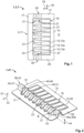
- Fig. 1 depicts a contact element 1 in a pre-assembly state 3.
- the contact element 1 is a sheet-metal part 7 made of a sheet metal 5.
- the contact element 1 is shown in a top view and is located in a plane 9. Plane 9 corresponds to the drawing plane. Contact element 1 comprises a frame 11 and contact springs 13.
- Plane 9 is spanned by a length direction 33 and a width direction 35.
- the entire contact element 1 is located in plane 9.
- a height direction 37 extends out of the drawing plane and is oriented perpendicular to plane 9.
- any number of contact springs 13 may be provided, e.g. one, two, three or a plurality thereof.
- Each of the contact springs 13, respectively the at least one contact spring 13 may be referred to as lamella 13a or - when two or more contact springs 13 are provided - a plurality of lamellae 13a.
- the plurality of contact springs 13 each have the same shape and geometry, e.g. length. In other embodiments, the contact springs 13 may differ from one another in shape and/or geometry.
- frame 11 comprises a first region 15 and a second region 17 that is arranged opposite the first region 15.
- the first region 15 is spaced apart from the second region 17 by a gap 23.
- Frame 11 further comprises a third region 29 and a fourth region 31.
- Each of the first 15, the second 17, the third 29 and the fourth region 31 is located at one side of the gap 23. All four regions 15, 17, 29, 31 encircle the gap 23.
- Contact element 1 has a rectangular shape or footprint.
- the shape or footprint may be different in other embodiments, e.g. square-shaped, curved, circular, etc. Accordingly, in embodiments having curved or circular regions of the frame 11 in particular, the contact springs 13 may differ in shape and/or geometry, in particular their length.
- the third region 29 may be provided.
- the gap 23 opens towards outside the frame 11 opposite the third region 29.
- hole 25 is formed by inner sides 27 of the second region 17, the third region 29 and the fourth region 31 and by an outer contour of the contact springs 13.
- the at least one contact spring 13 has a fixed end 19 which is fixed to the first region 17 of frame 11. Opposite the fixed end 19, the at least one contact spring 13 has a free end 21.
- the contact springs 13 extend from the first region 15 to the second region 17 across the gap 23. In the pre-assembly state 3, the free end 21 is located within the gap 23.
- the third region 29 and the fourth region 31 comprise a bending portion 39 that is adapted to be bent as will be shown in the following figures.
- the contact spring 13 also comprises bending portions 39.
- each of the contact springs 13 is a bent upwards, i.e. in the height direction 37 and extends in an acute angle out of plane 9.
- the first region 15 and the second region 17 are still located in plane 9, whereas the third region 29 and the fourth region 31 are only partially located in plane 9.
- the bending portion 39 of Fig. 1 is bent upwards out of plane 9, i.e. in the height direction 37 and subsequently bent downwards and bent back into plane 9.
- the bending portion 39 thus forms a bight 43.
- the bight 43 comprises a U-shaped section 45 in the embodiment shown and is a shortening fold 47.
- the U-shaped section 45 is a curved portion 46.
- Two bights 43 are provided that are located opposite to one another, wherein gap 23 is located between the bights 43.
- the bight 43 has the effect of a shortening of the third region 29 and the fourth region 31 along the length direction 33.
- the bights 43 have the effect that each of the contact springs 13 overlaps the second region 17 with the corresponding free end 21.
- Contact springs 13 are oriented essentially parallel to one another. Each contact spring 13 may be deflected elastically from a rest position 48 in a direction towards the gap 23, i.e. opposite the height direction 37.
- the contact springs 13 also comprise at least one curved portion 46 and an apex 49. To distinguish the elements, the curved portion 46 and the apex 49 of the bight 43 may be referred to as further curved portion 46a and further apex 49a.
- Each contact spring 13 comprises a plurality of U-shaped sections 45 (see also Fig. 3 ) , such that an apex 49 is formed.
- the apex 49 represents the highest point of each contact spring 13 and corresponds to a contact point 51 of the corresponding contact spring 13.
- Each contact spring 13 may be deflected individually, whereas an electrical contact with a mating contact (see Fig. 3 and 4 ) is established by the plurality of contact springs 13.
- the contact element 1 allows for a reliable electrical connection even if the mating contact does not have an even contact surface.
- each of the contact springs 13 may be deflected by a deflection distance 53 (see Fig. 3 ) that may be different for each contact spring 13.
- the possibility of contacting an uneven mating contact without deterioration of the electrical connection is one of the advantages of said contact element 1 having a multitude of contact springs 13.
- the bights 43 are further configured to protect the contact springs 13.
- the contact spring 13 are for instance not accessible from the sides, in particular from the third region 29 or the fourth region 31.
- the bights 43 protect the contact springs 13 to a certain amount against mechanical influences acting opposite the height direction 37.
- the bights 43 have a bight height 44 located further away from plane 9 then the apex 49 of contact springs 13. In other embodiments (not shown), the bight height 44 may equal the height of the apex 49.
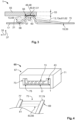
- Fig. 3 shows a partially cut side view of the contact element 1 which is in contact with a mating contact 55.
- the mating contact 55 may comprise a contact pad 56 or may be made entirely from a conductive material (not shown).
- Fig. 3 only schematically shows how an electric connection is established.
- the mating contact 55 is moved opposite the length direction 33, thereby exerting a deflection force 57 onto the contact springs 13.
- the contact spring 13 is deflected, in particular pivoted about the pivot point 59 that corresponds to the fixed end 19.
- the contact spring 13 is deflected towards gap 23 until the free end 21 of the contact spring 13 abuts the second region 17 of the frame 11 at a support point 58.
- the spring contact 13 may be further compressed opposite the height direction 37, which results in a compression of the curved shape of the contact spring 13, such that apex 49 is pressed towards the gap 23 and free end 21 is slightly dislocated in length direction 33.
- the entire contact spring 13 may be tilted around pivot point or pivot line 59.
- Fig. 3 schematically shows the contact spring 13 in the rest position 48 drawn with a dotted line as well as the deflection distance 53 mentioned above.
- the deflection distance 53 corresponds to the distance between a height position along the height direction 37 of apex 49 in the rest position 48 of the contact spring 13 and the height position of apex 49 in a compressed state 61 of the contact spring 13.
- the compressed state 61 of the contact spring 13 corresponds to a deflected position 62 of contact spring 13. In this deflected position 62, contact spring 13 is in mechanical contact with the second region 17 of frame 11.
- the free end 21 is in mechanical contact with the second region 17 and a contact force 63 is exerted by the contact spring 13 in height direction 37.
- the contact force 63 is oriented essentially normal to the mating contact 55 and may thus be referred to as normal contact force.
- an electrical connector assembly 65 is schematically shown.
- the electrical connector assembly 65 comprises an electrical connector 67 and a mating connector 69. Only in the embodiment shown the electrical connector represents a female connector and the mating connector a male connector. This may be different in other embodiments (not shown).
- the electrical connector67 (which is also shown in Fig. 5 in a front view) comprises a connector housing 71 with a connection recess 73 provided in the connector housing 71.
- the connection recess 73 represents a connector face 75 of the electrical connector 67.
- a contact element 1 is received in the connection recess 73.
- the contact element 1 may be inserted into the connector housing 71 via said connection recess 73 but may in other embodiments also be overmolded by the material of the connector housing 71. In any case, the contact element 1 is accessible via the connection recess 73.
- the bights 43 and the contact springs 13 are also visible and accessible via the connection recess 73.
- the second region 17 of the contact element 1 is supported by the connector housing 71, such that contact springs 13 may be supported by the second region 17 without the second region 17 deflecting away from contact springs 13.
- the mating connector 69 also has a connector face 75 that is essentially complementary to the connection recess 73.
- the mating connector 69 comprises two opposing guiding means 77 that are longitudinal key means 79.
- a plate member 81 connects the opposing guiding means 77 and provides a contact portion 83 that is located, respectively accessible from the lower side of the mating connector 69.
- the contact portion 83 is drawn with a dotted line.
- the contact portion 83 may be the contact pad 56 shown in Fig. 3 .
- Fig. 5 shows a front view of the electrical connector 67.
- a free distance 85 between the bights 43 and the connector housing 71 determines how far the guiding means 77 (see Fig. 4 ) may extend from plate member 81 in height direction 37.
- a lower side of the plate member 81 may abut the apex 49 of the bights 43.
- the corresponding apexes 49 are located at a further free distance 87 from the connector housing 71.
- the contact springs 13 are deflected towards the gap 23, i.e. opposite the height direction 37 for generating the necessary contact force 63 (see fig. 3 ).
- the plate member 81 of the mating connector 69 has a plate thickness 89 that determines the deflection distance 53.
- the deflection distance 53 is a difference of plate thickness 89 and the further free distance 87.
Landscapes
- Coupling Device And Connection With Printed Circuit (AREA)
- Details Of Connecting Devices For Male And Female Coupling (AREA)
Abstract
Description
- The invention relates to a contact element, an electrical connector for providing an electric connection with a mating connector and an electrical connector assembly.
- Contact elements, electrical connectors and electrical connector assemblies are commonly mass produced. There is a need to simplify these elements, while their versatility is maintained or even increased. There is also the need to simplify their production in order to reduce production costs.
- These needs are addressed by the invention in that the contact element comprises a frame and at least one contact spring, wherein the at least one contact spring has a fixed end, the fixed end being fixed to a first region of the frame, and a free end opposite the fixed end, wherein the frame further comprises a second region being arranged opposite the first region and spaced apart from the first region by a gap, wherein the at least one contact spring extends from the first region across the gap to the second region, and wherein the free end overlaps the second region.
- The above objectives are further addressed by the invention in that the electrical connector comprises a connector housing or connector body and a contact element described above, wherein the contact element is received and held in the connector housing and accessible via a connection recess in the connector housing and wherein the at least one contact element extends towards the connection recess
- The invention further solves these objectives in that the electrical connector assembly comprises an electrical connector described above and a mating connector that is adapted to be inserted into the electrical connector for providing an electric connection, wherein the mating connector comprises a cross section that is essentially complementary to the connection recess, wherein the mating connector is supported by the at least one bight, which is configured to prevent a movement of the mating connector towards the frame of the at least one contact element.
- The above contact element, the electrical connector and the electrical connector assembly have the advantage of a simplified geometry and/or shape and/or structure and consequently of production costs as well as reducing the amount of material required for producing one contact element. Further, by providing an overlap between the free end and the second region, the contact element is configured to prevent overbending of the at least one contact spring and to maintain or even increase a spring force that may be generated by the at least one contact spring.
- The contact element, the electrical connector and the electrical connector assembly may be improved by further features that will be described in the following. The features described below may be arbitrarily combined with one another and individual features may be omitted if the technical effect obtained by the omitted feature is not relevant. Each of the possible embodiments described in the following represents a specific combination of technical features and may be advantageous on its own. Features described by the contact element may be provided in the electrical connector or the electrical connector assembly and vice versa.
- The contact element may comprise any number of contact springs, i.e. two, three, four or a plurality thereof. The plurality of contact springs, i.e. two or more contact springs, may be oriented parallel to one another, wherein the at least one contact spring may be formed from the material of the gap, thereby reducing the amount of cut waste and thus production costs.
- The contact springs may have the same shape and/or geometry. However, each of the contact springs may have a shape and/or geometry different from the other contact springs.
- The contact element may have a rectangular shape or footprint. Corners of the contact element may provide a bevel. The contact element may have a squared shape or may even comprise curved regions. Exemplarily, the contact element may have a circular or elliptic footprint or a footprint similar to a circle or an ellipse, wherein the first and the second region are semicircle shaped or semi-elliptic shaped and each of the contact springs may have a different length and/or shape.
- Non-limiting exemplary ways to generate the overlap of the free end and the second region are processes like rolling, swaging or pressing of the at least one contact spring, such that the at least one contact spring is configured to be lengthened. These production steps may be applied to the at least one contact spring during the stamping process
- The contact element may be improved by the at least one contact spring being configured to be elastically deflected from a rest position in a direction towards the gap, and wherein, preferably at least in an elastically deflected position, the at least one contact spring rests against the second region of the frame.
- This has the advantage that the second region supports the deflected at least one contact spring, thereby increasing a contact force that may be provided by the contact element. The contact force may be understood as the force that may be exerted by a deflected contact spring against a mating contact element. Said contact force may be oriented perpendicular to the mating contact element and may thus be referred to as contact normal force.
- The frame of the contact element may be arranged in a plane and the at least one contact spring may be configured to be elastically deflected essentially perpendicular to said plane.
- Such a geometry and/or shape of the contact element is easy to produce, store or transport. Such essentially flat contact elements may comprise a tab connecting each of a plurality of contact elements with a carrier strip for reeling said carrier strip and the contact elements for easy transportation, storage or feeding in further processing steps.
- Preferably, the frame of the contact element may be formed from a sheet metal.
- This has the advantage that the contact elements may be produced by bending and stamping that may require one single production step and the advantage of a reduced amount of cut waste of the sheet material because of the improved geometry and/or shape of the contact element.
- The first and the second region as well as the gap may be located in a common plane.
- The contact element may be improved by the frame comprising a third region connecting the first and second region and wherein the third region comprises a bight.
- The provision of a bight has the advantage that, as the bight is provided in the third region, the overlap between the free end of the contact spring and the second region of the frame is provided. There is thus no need to lengthen the at least one contact spring as indicated in the examples above. As an alternative to lengthening the contact spring, the third region is shortened by the bight, having the same effect of providing the overlap without reducing integral strength of the at least one contact spring. As an example, as the lengthening of the at least one contact spring is avoided, the material thickness of the at least one contact spring may remain constant.
- The contact element may be further improved in that the bight may extend in a direction along which the at least one contact spring is configured to be elastically deflectable.
- This has the advantage that the bight may protect the at least one contact spring from being damaged by mechanical influences. The bight may thus extend out of the plane of the frame. The bight may protect the at least one contact spring at least partially from one, two, three or four sides.
- In a further embodiment of the contact element, the bight may extend over a part of the third region and may be located closer to the second region than to the first region.
- This position of the bight has the advantage that it is adapted to the deflection geometry of the at least one contact spring. Said at least one contact spring is preferably deflected at its free and not at its fixed end. The bight may represent a bending region of the frame, such that the position at which a contact force is generated by the at least one contact spring is preferably located close to the position of the bight. If the position of the exertion of contact force is located distal from the position of the bight, a part of the third region may act as a lever that increases the forces applied to the third region.
- The third region may at least, sectionwise or in its entirety, deviate from the straight line that connects its two end points, at which the third region is connected to first and second region. The part of the third region that comprises this deviation is termed bight in the following.
- The bight may comprise or consist of a form such as a bulge, an indentation, a protrusion or a convexity. The bight may comprise or consist of a curved section, e.g. a U-shape or may comprise or consist of more than one U-shape. In a different embodiment, the bight may comprise or consists of a folded section, e.g. comprising one or more V-shaped sections.
- The bight may comprise a plateau that is oriented essentially parallel to the plane in which the frame is located.
- The gap in the frame may be surrounded by the frame at at least three sides.
- The frame may comprise a fourth region connecting the first and the second region, wherein the gap extends between the third and the fourth region and between the first and the second region. The four regions may thus enclose the gap.
- The fourth region may comprise another bight. The fourth region may be formed symmetrically to the third region. Also, the other, i.e. the second bight may be formed symmetrically to the bight being the first bight in this embodiment. The bights may be addressed as pair of bights opposing one another.
- The bight may be a length-reducing formation and may be referred to as bump, fold, elevation or shortening fold. The bight may be is configured to reduce a length of the frame in a length direction, the length direction extending from the first portion to the second portion. The bight may be formed by a plastically deformed section of the frame, in particular a section of the third region or fourth region, respectively.
- The at least one contact spring may extend out of the plane of the frame. The direction into which the at least one contact spring extends may be considered an upward direction. The at least one contact spring may extend from the plane at an acute angle, i.e. partially in the upward direction and partially in the length direction
- The at least one contact spring may be configured to be elastically deflected towards the gap.
- In another advantageous embodiment of the contact element, the at least one contact spring may have at least one curved portion with an apex. The apex may be located at a distance referred to as height above the plane of the frame, wherein the apex is located closer to the free end of the at least one contact spring than to the fixed end of the contact spring.
- This geometry and/or shape and/or position of the at least one contact spring has the advantage of providing a sufficient deflection distance. Rather close to the fixed end of the at least one contact spring, a deflection distance is limited and may not meet the requirements on the contact element.
- Further, towards the free end of the at least one contact spring, the deflection distance increases as compared to a position closer to the fixed end. The curved portion with the apex may provide a defined contact area of the at least one contact spring. If the at least one contact spring is deflected, i.e. pivoted around the fixed end and the curved portion, the apex in particular is slightly tilted because of this pivotal movement. However, the contact position is still defined by said apex because it is not strongly dislocated in the length direction.
- The contact spring may have at least one convex portion of different possible shapes, e.g. U-shape or V-shape. The contact spring may comprise one or more U- or V-shaped sections or a combination thereof. The contact spring may, in particular, be convex.
- The contact element may be further improved by the bight. Exemplary, the bight may be a length-reducing formation, comprising at least one further curved portion with a further apex. Alternatively, a plateau is provided instead of an apex, wherein in the length direction, the apex of the at least one contact spring and the further apex of the length-reducing formation are located essentially at the same position.
- The at least one contact spring of the contact element, may be located at the same side of the frame as the bight, in particular in the height direction.
- This has the advantage that the bight or the pair of bights may protect the at least one contact spring. It is further advantageous that this embodiment of the contact element may be placed flat on or into a receiving structure, e.g. an electrical connector. Further advantages are discussed below with reference to the electrical connector.
- The protection of the at least one contact spring by the bight may be further improved by the at least one contact spring and the bight extending from the frame to essentially the same height. If a plurality of contact elements is reeled, the at least one contact spring of each contact element is protected against mechanical influences that may possibly be induced by the next layer of contact elements on the reel.
- Even a separate, i.e. single contact element provides protection of the at least one contact spring by means of the bight. The bight may prevent mechanical contact to the at least one contact spring. Said protection may be provided by one, two or three sides.
- The at least one contact spring of the contact element may have a compressed state, wherein in the biased state, the at least one contact spring may be deflected towards the gap, wherein the free end of the at least one contact spring may be configured to abut the second portion at least in the compressed state, and wherein the free end of the at least one contact spring may be further configured to move along the second portion of the frame.
- This embodiment has the advantage that the free end of the at least one contact spring abutting the second portion results in an increased contact force that may be exerted by the at least one contact spring towards a mating contact member. The contact force thus does not correspond to the force necessary to tilt the at least one contact spring around the fixed end, but corresponds to the force necessary to bend, in particular compress the curved contact spring.
- Exemplarily, the curved portion of the contact spring with the apex is actually not displaced along or opposite the deflection direction towards the gap, i.e. a baseline of said curve remains constant and remains in the plane of the frame, whereas the curved portion is compressed towards the gap, decreasing the height of the curved portion and displacing the apex towards the plane of the frame, wherein at the same time a width of the curved portion is increased. The at least one spring member is thus not deflected in a pivotal manner but in a compressing manner. Depending on the geometry and/or shape of the curved section, the possible contact forces obtained by deformation of the spring member may be several times larger than possible contact forces obtained by pivotal deflection of the spring member. Said contact forces may be 2 to 20 times larger if the contact spring is deformed. Further, an overbending of the contact spring may be prevented.
- In the electrical connector, any of the above contact elements may be provided.
- As discussed above, the contact element is received and held in the connector housing of the electrical connector and is accessible via a connection recess that may form the connector face of the electrical connector.
- When received in the connector housing, the entire frame of the contact element may be supported by the housing body.
- The electrical connector comprises the electrical connector described above and a mating connector. When the mating connector is inserted into the electrical connector, a mating contact of the mating connector establishes an electric connection with the contact member, in particular with the at least one contact spring of the contact member that is received in the electrical connector.
- Preferably, the cross sections of the mating connector and the connection recess of the electrical connector are complementary to one another. These cross sections may have orientation features that prevent the mating connector from being connected to the electrical connector in an incorrect orientation.
- In order to protect the at least one contact spring of the contact member against application of a force exceeding the maximum allowable force to be exerted onto the contact spring (exceeding this threshold force may result in an overbending, permanent deformation or damage of the contact spring), a section of the mating connector, i.e. a portion of the mating connector housing or a portion of the mating contact may abut the bight or preferably the pair of bights of the contact element provided in the electrical connector.
- The bight may support the mating connector, in particular, in a direction towards the frame of the contact member. This may prevent unwanted movement of the mating contact of the mating connector towards the frame. A deflection of the at least one contact spring towards the gap may therefore be determined only by the geometry of the mating contact. In particular, the height of the mating contact may determine the amount of deflection of the at least one contact spring towards the gap.
- The electrical connector assembly may be further improved by the contact element comprising two opposing bights that are configured to receive a portion of the mating connector between the bights and that are configured to guide a portion of the mating connector during insertion of the mating connector into the electrical connector.
- A mating contact may be a metallic or a metallized tab, wherein a width direction is oriented perpendicular to the length direction and the height direction may be equal or smaller than a distance between two bights of the contact element. The bights may thus form a receiving or guiding slot for the mating contact.
- In the following, the contact element, the electrical connector and the electrical connector assembly are explained in detail by the accompanying figures. In the figures, specific embodiments are exemplarily shown. These embodiments are not intended to limit the scope of the present disclosure. In the detailed description, the same features and features having the same technical effect are referred to by the same reference numeral. Repetitive descriptions are avoided, whereas differences between the embodiments shown in the figures are explicitly mentioned.
- The figures show:
- Fig. 1
- a contact element of the stamping process;
- Fig. 2
- a contact element in an assembly state;
- Fig. 3
- a contact element in a cut side view contacting with a mating contact;
- Fig. 4
- an electrical connector assembly comprising an electrical connector and a mating connector; and
- Fig. 5
- a front view of the electrical connector of
Fig. 4 . -
Fig. 1 depicts acontact element 1 in a pre-assembly state 3. Thecontact element 1 is a sheet-metal part 7 made of a sheet metal 5. - The
contact element 1 is shown in a top view and is located in aplane 9.Plane 9 corresponds to the drawing plane.Contact element 1 comprises a frame 11 and contact springs 13. -
Plane 9 is spanned by alength direction 33 and awidth direction 35. In the pre-assembly state 3 theentire contact element 1 is located inplane 9. Aheight direction 37 extends out of the drawing plane and is oriented perpendicular toplane 9. - In the specific embodiment shown in
Fig. 1 an overall number of eight contact springs 13 is provided. In different embodiments of thecontact element 1 any number of contact springs 13 may be provided, e.g. one, two, three or a plurality thereof. Each of the contact springs 13, respectively the at least onecontact spring 13 may be referred to as lamella 13a or - when two or more contact springs 13 are provided - a plurality of lamellae 13a. - In the embodiment shown, the plurality of contact springs 13 each have the same shape and geometry, e.g. length. In other embodiments, the contact springs 13 may differ from one another in shape and/or geometry.
- In the specific embodiment shown, frame 11 comprises a
first region 15 and asecond region 17 that is arranged opposite thefirst region 15. Thefirst region 15 is spaced apart from thesecond region 17 by agap 23. Frame 11 further comprises athird region 29 and afourth region 31. Each of the first 15, the second 17, the third 29 and thefourth region 31 is located at one side of thegap 23. All fourregions gap 23.Contact element 1 has a rectangular shape or footprint. The shape or footprint may be different in other embodiments, e.g. square-shaped, curved, circular, etc. Accordingly, in embodiments having curved or circular regions of the frame 11 in particular, the contact springs 13 may differ in shape and/or geometry, in particular their length. - In a different embodiment (not shown) only the
third region 29 may be provided. In this case, thegap 23 opens towards outside the frame 11 opposite thethird region 29. - In the case of a stamped sheet metal part 7, the
gap 23 is produced by stamping ahole 25 in the sheet metal 5. In the embodiment shown,hole 25 is formed byinner sides 27 of thesecond region 17, thethird region 29 and thefourth region 31 and by an outer contour of the contact springs 13. - The at least one
contact spring 13 has a fixedend 19 which is fixed to thefirst region 17 of frame 11. Opposite thefixed end 19, the at least onecontact spring 13 has afree end 21. - The contact springs 13 extend from the
first region 15 to thesecond region 17 across thegap 23. In the pre-assembly state 3, thefree end 21 is located within thegap 23. - In the embodiment shown, the
third region 29 and thefourth region 31 comprise a bendingportion 39 that is adapted to be bent as will be shown in the following figures. - It is to be noted that the
contact spring 13 also comprises bendingportions 39. - In
Fig. 2 , thecontact element 1 is shown in the bent or assembly-state 41. In the assembly-state 41, each of the contact springs 13 is a bent upwards, i.e. in theheight direction 37 and extends in an acute angle out ofplane 9. - The
first region 15 and thesecond region 17 are still located inplane 9, whereas thethird region 29 and thefourth region 31 are only partially located inplane 9. - The bending
portion 39 ofFig. 1 is bent upwards out ofplane 9, i.e. in theheight direction 37 and subsequently bent downwards and bent back intoplane 9. The bendingportion 39 thus forms abight 43. Thebight 43 comprises a U-shaped section 45 in the embodiment shown and is a shortening fold 47. The U-shaped section 45 is a curved portion 46. - Two
bights 43 are provided that are located opposite to one another, whereingap 23 is located between thebights 43. - The
bight 43 has the effect of a shortening of thethird region 29 and thefourth region 31 along thelength direction 33. Thebights 43 have the effect that each of the contact springs 13 overlaps thesecond region 17 with the correspondingfree end 21. - Contact springs 13 are oriented essentially parallel to one another. Each
contact spring 13 may be deflected elastically from a rest position 48 in a direction towards thegap 23, i.e. opposite theheight direction 37. The contact springs 13 also comprise at least one curved portion 46 and an apex 49. To distinguish the elements, the curved portion 46 and the apex 49 of thebight 43 may be referred to as furthercurved portion 46a andfurther apex 49a. - If the
contact spring 13 is deflected from the rest position 48 towards thegap 23, thecontact spring 13 rests against thesecond region 17 of the frame 11 with the correspondingfree end 21. - Each
contact spring 13 comprises a plurality of U-shaped sections 45 (see alsoFig. 3 ) , such that an apex 49 is formed. The apex 49 represents the highest point of eachcontact spring 13 and corresponds to a contact point 51 of thecorresponding contact spring 13. - Each
contact spring 13 may be deflected individually, whereas an electrical contact with a mating contact (seeFig. 3 and 4 ) is established by the plurality of contact springs 13. Thecontact element 1 allows for a reliable electrical connection even if the mating contact does not have an even contact surface. - In the case of such an uneven contact surface, each of the contact springs 13 may be deflected by a deflection distance 53 (see
Fig. 3 ) that may be different for eachcontact spring 13. The possibility of contacting an uneven mating contact without deterioration of the electrical connection is one of the advantages of saidcontact element 1 having a multitude of contact springs 13. - The
bights 43 are further configured to protect the contact springs 13. Thecontact spring 13 are for instance not accessible from the sides, in particular from thethird region 29 or thefourth region 31. In addition, thebights 43 protect the contact springs 13 to a certain amount against mechanical influences acting opposite theheight direction 37. In the embodiment shown, thebights 43 have abight height 44 located further away fromplane 9 then the apex 49 of contact springs 13. In other embodiments (not shown), thebight height 44 may equal the height of the apex 49. -
Fig. 3 shows a partially cut side view of thecontact element 1 which is in contact with amating contact 55. Themating contact 55 may comprise acontact pad 56 or may be made entirely from a conductive material (not shown). -
Fig. 3 only schematically shows how an electric connection is established. Themating contact 55 is moved opposite thelength direction 33, thereby exerting adeflection force 57 onto the contact springs 13. Thecontact spring 13 is deflected, in particular pivoted about the pivot point 59 that corresponds to thefixed end 19. - First, the
contact spring 13 is deflected towardsgap 23 until thefree end 21 of thecontact spring 13 abuts thesecond region 17 of the frame 11 at asupport point 58. - Depending on the
mating contact 55 applied, thespring contact 13 may be further compressed opposite theheight direction 37, which results in a compression of the curved shape of thecontact spring 13, such thatapex 49 is pressed towards thegap 23 andfree end 21 is slightly dislocated inlength direction 33. - Prior to this compression, the
entire contact spring 13 may be tilted around pivot point or pivot line 59. -
Fig. 3 schematically shows thecontact spring 13 in the rest position 48 drawn with a dotted line as well as thedeflection distance 53 mentioned above. Thedeflection distance 53 corresponds to the distance between a height position along theheight direction 37 ofapex 49 in the rest position 48 of thecontact spring 13 and the height position ofapex 49 in a compressed state 61 of thecontact spring 13. The compressed state 61 of thecontact spring 13 corresponds to a deflected position 62 ofcontact spring 13. In this deflected position 62,contact spring 13 is in mechanical contact with thesecond region 17 of frame 11. - At least in the compressed state 61 (shown in
Fig. 3 ), thefree end 21 is in mechanical contact with thesecond region 17 and acontact force 63 is exerted by thecontact spring 13 inheight direction 37. Thecontact force 63 is oriented essentially normal to themating contact 55 and may thus be referred to as normal contact force. - In
Fig. 4 , anelectrical connector assembly 65 is schematically shown. Theelectrical connector assembly 65 comprises anelectrical connector 67 and amating connector 69. Only in the embodiment shown the electrical connector represents a female connector and the mating connector a male connector. This may be different in other embodiments (not shown). - The electrical connector67 (which is also shown in
Fig. 5 in a front view) comprises aconnector housing 71 with aconnection recess 73 provided in theconnector housing 71. Theconnection recess 73 represents aconnector face 75 of theelectrical connector 67. - A
contact element 1 is received in theconnection recess 73. Thecontact element 1 may be inserted into theconnector housing 71 via saidconnection recess 73 but may in other embodiments also be overmolded by the material of theconnector housing 71. In any case, thecontact element 1 is accessible via theconnection recess 73. - The
bights 43 and the contact springs 13 are also visible and accessible via theconnection recess 73. Thesecond region 17 of thecontact element 1 is supported by theconnector housing 71, such that contact springs 13 may be supported by thesecond region 17 without thesecond region 17 deflecting away from contact springs 13. - The
mating connector 69 also has aconnector face 75 that is essentially complementary to theconnection recess 73. In the embodiment shown, themating connector 69 comprises two opposing guiding means 77 that are longitudinal key means 79. - A
plate member 81 connects the opposing guiding means 77 and provides a contact portion 83 that is located, respectively accessible from the lower side of themating connector 69. The contact portion 83 is drawn with a dotted line. The contact portion 83 may be thecontact pad 56 shown inFig. 3 . - The established electrical connection between contact portion 83 of the mating connector and contact springs 13 of the
electrical connector 67 is indicated inFig. 3 . -
Fig. 5 shows a front view of theelectrical connector 67. Afree distance 85 between thebights 43 and theconnector housing 71 determines how far the guiding means 77 (seeFig. 4 ) may extend fromplate member 81 inheight direction 37. A lower side of theplate member 81 may abut the apex 49 of thebights 43. - In the rest position 48 of the contact springs 13, the corresponding
apexes 49 are located at a furtherfree distance 87 from theconnector housing 71. In order to obtain a secure electric connection, the contact springs 13 are deflected towards thegap 23, i.e. opposite theheight direction 37 for generating the necessary contact force 63 (seefig. 3 ). - The
plate member 81 of themating connector 69 has aplate thickness 89 that determines thedeflection distance 53. Thedeflection distance 53 is a difference ofplate thickness 89 and the furtherfree distance 87. -
- 1
- contact element
- 3
- pre-assembly state
- 5
- sheet metal
- 7
- sheet-metal part
- 9
- plane
- 11
- frame
- 13
- contact spring
- 13a
- lamella
- 15
- first region
- 17
- second region
- 19
- fixed end
- 21
- free end
- 23
- gap
- 25
- hole
- 27
- in a side
- 29
- third region
- 31
- fourth region
- 33
- length direction
- 35
- width direction
- 37
- height direction
- 39
- bending portion
- 41
- assembly state
- 43
- bight
- 44
- bight height
- 45
- U-shaped section
- 46
- curved portion
- 46a
- further curved portion
- 47
- shortening fold
- 48
- rest position
- 49
- apex
- 49a
- further apex
- 51
- contact point
- 53
- deflection distance
- 55
- mating contact
- 56
- contact pad
- 57
- deflection force
- 58
- support point
- 59
- pivot point
- 61
- compressed state
- 62
- deflected position
- 63
- contact force
- 65
- electrical connector assembly
- 67
- electrical connector
- 69
- mating connector
- 71
- connector housing
- 73
- connection recess
- 75
- connector face
- 77
- guiding means
- 79
- longitudinal key means
- 81
- plate member
- 83
- contact portion
- 85
- free distance
- 87
- further free distance
- 89
- plate thickness
Claims (15)
- Contact element (1) comprising a frame (11) and at least one contact spring (13), wherein the at least one contact spring (13) has a fixed end (19), the fixed end (19) being fixed to a first region (15) of the frame (11), and a free end (21) opposite the fixed end (19), wherein the frame (11) further comprises a second region (17) being arranged opposite the first region (15) and spaced apart from the first region (15) by a gap (23), wherein the at least one contact spring (13) extends from the first region (15) across the gap (23) to the second region (17), and wherein the free end (21) overlaps the second region (17).
- Contact element (1) according to claim 1, wherein the at least one contact spring (13) is configured to be elastically deflected from a rest position (48) in a direction towards the gap (23), and wherein, in an elastically deflected position (62), the at least one contact spring (13) rests against the second region (17) of the frame (11).
- Contact element (1) according to claim 1 or 2, wherein the frame (11) is arranged in a plane (9) and the at least one contact spring (13) is configured to be elastically deflected essentially perpendicular to said plane (9).
- Contact element (1) according to any one of claims 1 to 3, wherein the frame (11) is formed from a sheet metal (5).
- Contact element (1) according to any one of claims 1 to 4, wherein the frame (11) comprises a third region (29) connecting the first (15) and second region (17) and wherein the third region (29) comprises a bight (43).
- Contact element (1) according to claim 5, wherein the bight (43) extends in a direction along which the at least one contact spring (13) is configured to be elastically deflectable.
- Contact element (1) according to claim 5 or 6, wherein the bight (43) extends over a part of the third section (29) and is located closer to the second region (17) than to the first region (15).
- Contact element (1) according to any one of claims 3 to 7, wherein the at least one contact spring (13) has at least one curved portion (46) with an apex (49), the apex (49) being located at a height above the plane (9) of the frame (11), wherein the apex (49) is located closer to the free end (41) of the at least one contact spring (13) than to the fixed end (19) of the at least one contact spring (13).
- Contact element (1) according to claim 8, wherein the bight (43) comprises at least one further curved portion (46a) with a further apex (49a) and wherein, in the length direction (33), the apex (49) of the at least one contact spring (13) and the further apex (49a) of the bight (43) are located essentially at the same position.
- Contact element (1) according to any one of claims 5 to 9, wherein the at least one contact spring (13) is located at the same side of the frame (11) as the bight (43).
- Contact element (1) according to any one of claims 5 to 10, wherein the at least one contact spring (13) and the bight (43) extend from the frame (11) to essentially the same height.
- Contact element (1) according to any one of claims 1 to 11, wherein the at least one contactspring (13) has a compressed state (61), wherein, in the compressed state (61), the at least one contact spring (13) is deflected towards the gap (23), wherein the free end (21) of the at least one contact spring (13) is configured to abut the second portion (17) at least in the compressed state (61), and wherein the free end (21) of the at least one contact spring (13) is further configured to move along the second portion (17) of the frame (11).
- Electrical connector (67) for providing an electric connection with a mating connector (69), the electrical connector (67) comprises a connector housing (71) and a contact element (1) according to any one of claims 1 to 12, wherein the contact element (1) is received and held in the connector housing (71) and accessible via a connection recess (73) in the connector housing (71), wherein the at least one contact element (1) extends towards the connection recess (73).
- Electrical connector assembly (65) comprising an electrical connector (67) according to claim 13 and a mating connector (69) that is adapted to be inserted into the electrical connector (67) for providing an electric connection, wherein the mating connector (69) comprises a cross section that is essentially complementary to the connection recess (73), wherein the mating connector (69) is supported by the at least one bight (43), which is configured to prevent a movement of the mating connector (69) towards the frame (11) of the at least one contact element (1).
- Electrical connector assembly (65) according to claim 14, wherein the contact element (1) comprises two opposing bights (43) that are configured to receive a portion (77) of the mating connector (69) between the bights (43) and are configured to guide the portion (77) of the mating connector during insertion of the mating connector (69) into the electrical connector (67).
Priority Applications (5)
| Application Number | Priority Date | Filing Date | Title |
|---|---|---|---|
| EP22157333.0A EP4231460A1 (en) | 2022-02-17 | 2022-02-17 | Contact element, electrical connector and electrical connector assembly |
| CN202310114157.6A CN116613559A (en) | 2022-02-17 | 2023-02-14 | Contact element, electrical connector and electrical connector assembly |
| JP2023020490A JP7524380B2 (en) | 2022-02-17 | 2023-02-14 | Contact element, electrical connector and electrical connector assembly |
| KR1020230020011A KR102748799B1 (en) | 2022-02-17 | 2023-02-15 | Contact element, electrical connector and electrical connector assembly |
| US18/110,930 US12614868B2 (en) | 2022-02-17 | 2023-02-17 | Contact element, electrical connector and electrical connector assembly |
Applications Claiming Priority (1)
| Application Number | Priority Date | Filing Date | Title |
|---|---|---|---|
| EP22157333.0A EP4231460A1 (en) | 2022-02-17 | 2022-02-17 | Contact element, electrical connector and electrical connector assembly |
Publications (1)
| Publication Number | Publication Date |
|---|---|
| EP4231460A1 true EP4231460A1 (en) | 2023-08-23 |
Family
ID=80683131
Family Applications (1)
| Application Number | Title | Priority Date | Filing Date |
|---|---|---|---|
| EP22157333.0A Pending EP4231460A1 (en) | 2022-02-17 | 2022-02-17 | Contact element, electrical connector and electrical connector assembly |
Country Status (5)
| Country | Link |
|---|---|
| US (1) | US12614868B2 (en) |
| EP (1) | EP4231460A1 (en) |
| JP (1) | JP7524380B2 (en) |
| KR (1) | KR102748799B1 (en) |
| CN (1) | CN116613559A (en) |
Cited By (1)
| Publication number | Priority date | Publication date | Assignee | Title |
|---|---|---|---|---|
| WO2025251309A1 (en) * | 2024-06-07 | 2025-12-11 | Robert Bosch Gmbh | Plug connector |
Citations (8)
| Publication number | Priority date | Publication date | Assignee | Title |
|---|---|---|---|---|
| EP0674358A1 (en) * | 1994-03-21 | 1995-09-27 | Connecteurs Cinch | Female electrical contact element |
| FR2743942A1 (en) * | 1996-01-24 | 1997-07-25 | Cinch Connecteurs Sa | FEMALE ELECTRIC CONTACT MEMBER |
| US6299492B1 (en) * | 1998-08-20 | 2001-10-09 | A. W. Industries, Incorporated | Electrical connectors |
| US20020187666A1 (en) * | 2001-06-08 | 2002-12-12 | J.S.T.Mfg. Co.,Ltd. | Contact and electric connector onto which the contact is mounted |
| WO2004001906A1 (en) * | 2002-06-24 | 2003-12-31 | Fci | Connection device for flexible circuit |
| US7766668B1 (en) * | 2009-02-11 | 2010-08-03 | Avx Corporation | Low profile electrical conductor assembly for interconnecting conductive components in a stacked configuration |
| DE102016104868B3 (en) * | 2016-03-16 | 2017-05-24 | Wago Verwaltungsgesellschaft Mbh | Spring clamping element |
| US20190148872A1 (en) * | 2017-11-15 | 2019-05-16 | Foxconn Interconnect Technology Limited | Electrical connector having complementary configurations of opposite contacts |
Family Cites Families (10)
| Publication number | Priority date | Publication date | Assignee | Title |
|---|---|---|---|---|
| US4299436A (en) * | 1980-02-06 | 1981-11-10 | Universal Instruments Corporation | Electrical connector |
| US4790779A (en) * | 1987-05-06 | 1988-12-13 | Amp Incorporated | Burn-in socket for zig-zag inline semiconductor package |
| DE10156233A1 (en) | 2001-08-17 | 2003-03-06 | Sorig Ludger | Electrical plug contact body is made from single stamped flexible part with section with plug-in shaft for flat plug with inwardly directed lamellas, second section connected to bus bar |
| US7918671B2 (en) * | 2004-07-13 | 2011-04-05 | Research In Motion Limited | Mounting structure with springs biasing towards a latching edge |
| JP5852056B2 (en) | 2013-06-28 | 2016-02-03 | タイコエレクトロニクスジャパン合同会社 | Card connectors and contacts |
| CN203932406U (en) | 2014-04-24 | 2014-11-05 | 王嘉鑫 | Terminal structure of electrical connector |
| CN106033850B (en) * | 2015-03-13 | 2019-01-04 | 小米科技有限责任公司 | Smart card deck and electronic equipment |
| DE102015216632A1 (en) | 2015-08-31 | 2017-03-02 | Te Connectivity Germany Gmbh | Arrangement for establishing an electrical connection between a flat contact and a high-current conductor |
| EP3391471B1 (en) | 2015-12-17 | 2023-03-22 | TE Connectivity Germany GmbH | Rail socket with improved current transmission |
| EP3783744B1 (en) | 2019-08-23 | 2026-03-25 | Yazaki Europe Ltd. | Electric connection arrangement |
-
2022
- 2022-02-17 EP EP22157333.0A patent/EP4231460A1/en active Pending
-
2023
- 2023-02-14 CN CN202310114157.6A patent/CN116613559A/en active Pending
- 2023-02-14 JP JP2023020490A patent/JP7524380B2/en active Active
- 2023-02-15 KR KR1020230020011A patent/KR102748799B1/en active Active
- 2023-02-17 US US18/110,930 patent/US12614868B2/en active Active
Patent Citations (8)
| Publication number | Priority date | Publication date | Assignee | Title |
|---|---|---|---|---|
| EP0674358A1 (en) * | 1994-03-21 | 1995-09-27 | Connecteurs Cinch | Female electrical contact element |
| FR2743942A1 (en) * | 1996-01-24 | 1997-07-25 | Cinch Connecteurs Sa | FEMALE ELECTRIC CONTACT MEMBER |
| US6299492B1 (en) * | 1998-08-20 | 2001-10-09 | A. W. Industries, Incorporated | Electrical connectors |
| US20020187666A1 (en) * | 2001-06-08 | 2002-12-12 | J.S.T.Mfg. Co.,Ltd. | Contact and electric connector onto which the contact is mounted |
| WO2004001906A1 (en) * | 2002-06-24 | 2003-12-31 | Fci | Connection device for flexible circuit |
| US7766668B1 (en) * | 2009-02-11 | 2010-08-03 | Avx Corporation | Low profile electrical conductor assembly for interconnecting conductive components in a stacked configuration |
| DE102016104868B3 (en) * | 2016-03-16 | 2017-05-24 | Wago Verwaltungsgesellschaft Mbh | Spring clamping element |
| US20190148872A1 (en) * | 2017-11-15 | 2019-05-16 | Foxconn Interconnect Technology Limited | Electrical connector having complementary configurations of opposite contacts |
Cited By (1)
| Publication number | Priority date | Publication date | Assignee | Title |
|---|---|---|---|---|
| WO2025251309A1 (en) * | 2024-06-07 | 2025-12-11 | Robert Bosch Gmbh | Plug connector |
Also Published As
| Publication number | Publication date |
|---|---|
| JP2023120161A (en) | 2023-08-29 |
| US20230261407A1 (en) | 2023-08-17 |
| KR20230123890A (en) | 2023-08-24 |
| KR102748799B1 (en) | 2024-12-30 |
| CN116613559A (en) | 2023-08-18 |
| JP7524380B2 (en) | 2024-07-29 |
| US12614868B2 (en) | 2026-04-28 |
Similar Documents
| Publication | Publication Date | Title |
|---|---|---|
| JP6446559B2 (en) | Contact elements and mounting configurations using contact elements | |
| US7351122B2 (en) | Receptacle terminal | |
| KR100503824B1 (en) | One Piece Contact Spring | |
| US7481685B2 (en) | Female terminal fitting | |
| US8317529B2 (en) | Contact and electrical connector | |
| EP4383468A2 (en) | Electrical socket | |
| EP2107645A1 (en) | A terminal fitting | |
| US12614868B2 (en) | Contact element, electrical connector and electrical connector assembly | |
| US6790100B2 (en) | Female terminal fitting | |
| US6319076B1 (en) | Socket contact element | |
| JPH0927368A (en) | Female terminal | |
| US20090247001A1 (en) | Female terminal and chain terminal thereof | |
| CN114122764B (en) | Terminal part and chain terminal | |
| KR102949175B1 (en) | A plug equipped with a guide plate | |
| CN1758485B (en) | plug connector | |
| EP2575215B1 (en) | Terminal fitting | |
| JPH08250172A (en) | Receptacle type terminal | |
| US11381009B2 (en) | Contact and connector | |
| EP3783744B1 (en) | Electric connection arrangement | |
| WO1998038698A1 (en) | Electrical connector | |
| JP2009123597A (en) | Terminal fitting, and connection structure between terminal fitting and conductor | |
| US20240154342A1 (en) | Housing for an electrical lamella spring contact and contact assembly with a housing | |
| JP2026084443A (en) | Electrical connection terminals | |
| JP4948376B2 (en) | Terminal chain | |
| JP5331383B2 (en) | Female terminal |
Legal Events
| Date | Code | Title | Description |
|---|---|---|---|
| PUAI | Public reference made under article 153(3) epc to a published international application that has entered the european phase |
Free format text: ORIGINAL CODE: 0009012 |
|
| STAA | Information on the status of an ep patent application or granted ep patent |
Free format text: STATUS: THE APPLICATION HAS BEEN PUBLISHED |
|
| AK | Designated contracting states |
Kind code of ref document: A1 Designated state(s): AL AT BE BG CH CY CZ DE DK EE ES FI FR GB GR HR HU IE IS IT LI LT LU LV MC MK MT NL NO PL PT RO RS SE SI SK SM TR |
|
| STAA | Information on the status of an ep patent application or granted ep patent |
Free format text: STATUS: REQUEST FOR EXAMINATION WAS MADE |
|
| 17P | Request for examination filed |
Effective date: 20240223 |
|
| RBV | Designated contracting states (corrected) |
Designated state(s): AL AT BE BG CH CY CZ DE DK EE ES FI FR GB GR HR HU IE IS IT LI LT LU LV MC MK MT NL NO PL PT RO RS SE SI SK SM TR |
|
| RAP1 | Party data changed (applicant data changed or rights of an application transferred) |
Owner name: TE CONNECTIVITY INDIA PRIVATE LIMITED Owner name: TE CONNECTIVITY SOLUTIONS GMBH |
|
| STAA | Information on the status of an ep patent application or granted ep patent |
Free format text: STATUS: EXAMINATION IS IN PROGRESS |
|
| 17Q | First examination report despatched |
Effective date: 20250610 |