EP4230887A1 - Rotating assembly, folding mechanism, and foldable terminal - Google Patents
Rotating assembly, folding mechanism, and foldable terminal Download PDFInfo
- Publication number
- EP4230887A1 EP4230887A1 EP22778460.0A EP22778460A EP4230887A1 EP 4230887 A1 EP4230887 A1 EP 4230887A1 EP 22778460 A EP22778460 A EP 22778460A EP 4230887 A1 EP4230887 A1 EP 4230887A1
- Authority
- EP
- European Patent Office
- Prior art keywords
- slideway
- swing arm
- rotating shaft
- rotating
- limiting platform
- Prior art date
- Legal status (The legal status is an assumption and is not a legal conclusion. Google has not performed a legal analysis and makes no representation as to the accuracy of the status listed.)
- Granted
Links
Images





Classifications
-
- G—PHYSICS
- G09—EDUCATION; CRYPTOGRAPHY; DISPLAY; ADVERTISING; SEALS
- G09F—DISPLAYING; ADVERTISING; SIGNS; LABELS OR NAME-PLATES; SEALS
- G09F9/00—Indicating arrangements for variable information in which the information is built-up on a support by selection or combination of individual elements
- G09F9/30—Indicating arrangements for variable information in which the information is built-up on a support by selection or combination of individual elements in which the desired character or characters are formed by combining individual elements
- G09F9/301—Indicating arrangements for variable information in which the information is built-up on a support by selection or combination of individual elements in which the desired character or characters are formed by combining individual elements flexible foldable or roll-able electronic displays, e.g. thin LCD, OLED
-
- H—ELECTRICITY
- H05—ELECTRIC TECHNIQUES NOT OTHERWISE PROVIDED FOR
- H05K—PRINTED CIRCUITS; CASINGS OR CONSTRUCTIONAL DETAILS OF ELECTRIC APPARATUS; MANUFACTURE OF ASSEMBLAGES OF ELECTRICAL COMPONENTS
- H05K5/00—Casings, cabinets or drawers for electric apparatus
- H05K5/02—Details
- H05K5/0217—Mechanical details of casings
- H05K5/0226—Hinges
-
- F—MECHANICAL ENGINEERING; LIGHTING; HEATING; WEAPONS; BLASTING
- F16—ENGINEERING ELEMENTS AND UNITS; GENERAL MEASURES FOR PRODUCING AND MAINTAINING EFFECTIVE FUNCTIONING OF MACHINES OR INSTALLATIONS; THERMAL INSULATION IN GENERAL
- F16C—SHAFTS; FLEXIBLE SHAFTS; ELEMENTS OR CRANKSHAFT MECHANISMS; ROTARY BODIES OTHER THAN GEARING ELEMENTS; BEARINGS
- F16C11/00—Pivots; Pivotal connections
- F16C11/04—Pivotal connections
- F16C11/045—Pivotal connections with at least a pair of arms pivoting relatively to at least one other arm, all arms being mounted on one pin
-
- G—PHYSICS
- G06—COMPUTING OR CALCULATING; COUNTING
- G06F—ELECTRIC DIGITAL DATA PROCESSING
- G06F1/00—Details not covered by groups G06F3/00 - G06F13/00 and G06F21/00
- G06F1/16—Constructional details or arrangements
- G06F1/1613—Constructional details or arrangements for portable computers
- G06F1/1615—Constructional details or arrangements for portable computers with several enclosures having relative motions, each enclosure supporting at least one I/O or computing function
- G06F1/1616—Constructional details or arrangements for portable computers with several enclosures having relative motions, each enclosure supporting at least one I/O or computing function with folding flat displays, e.g. laptop computers or notebooks having a clamshell configuration, with body parts pivoting to an open position around an axis parallel to the plane they define in closed position
-
- G—PHYSICS
- G06—COMPUTING OR CALCULATING; COUNTING
- G06F—ELECTRIC DIGITAL DATA PROCESSING
- G06F1/00—Details not covered by groups G06F3/00 - G06F13/00 and G06F21/00
- G06F1/16—Constructional details or arrangements
- G06F1/1613—Constructional details or arrangements for portable computers
- G06F1/1633—Constructional details or arrangements of portable computers not specific to the type of enclosures covered by groups G06F1/1615 - G06F1/1626
- G06F1/1675—Miscellaneous details related to the relative movement between the different enclosures or enclosure parts
- G06F1/1681—Details related solely to hinges
-
- H—ELECTRICITY
- H04—ELECTRIC COMMUNICATION TECHNIQUE
- H04M—TELEPHONIC COMMUNICATION
- H04M1/00—Substation equipment, e.g. for use by subscribers
- H04M1/02—Constructional features of telephone sets
- H04M1/0202—Portable telephone sets, e.g. cordless phones, mobile phones or bar type handsets
- H04M1/0206—Portable telephones comprising a plurality of mechanically joined movable body parts, e.g. hinged housings
- H04M1/0208—Portable telephones comprising a plurality of mechanically joined movable body parts, e.g. hinged housings characterized by the relative motions of the body parts
- H04M1/0214—Foldable telephones, i.e. with body parts pivoting to an open position around an axis parallel to the plane they define in closed position
- H04M1/0216—Foldable in one direction, i.e. using a one degree of freedom hinge
- H04M1/022—The hinge comprising two parallel pivoting axes
-
- E—FIXED CONSTRUCTIONS
- E05—LOCKS; KEYS; WINDOW OR DOOR FITTINGS; SAFES
- E05D—HINGES OR SUSPENSION DEVICES FOR DOORS, WINDOWS OR WINGS
- E05D11/00—Additional features or accessories of hinges
- E05D11/06—Devices for limiting the opening movement of hinges
-
- E—FIXED CONSTRUCTIONS
- E05—LOCKS; KEYS; WINDOW OR DOOR FITTINGS; SAFES
- E05D—HINGES OR SUSPENSION DEVICES FOR DOORS, WINDOWS OR WINGS
- E05D3/00—Hinges with pins
- E05D3/06—Hinges with pins with two or more pins
-
- E—FIXED CONSTRUCTIONS
- E05—LOCKS; KEYS; WINDOW OR DOOR FITTINGS; SAFES
- E05Y—INDEXING SCHEME ASSOCIATED WITH SUBCLASSES E05D AND E05F, RELATING TO CONSTRUCTION ELEMENTS, ELECTRIC CONTROL, POWER SUPPLY, POWER SIGNAL OR TRANSMISSION, USER INTERFACES, MOUNTING OR COUPLING, DETAILS, ACCESSORIES, AUXILIARY OPERATIONS NOT OTHERWISE PROVIDED FOR, APPLICATION THEREOF
- E05Y2999/00—Subject-matter not otherwise provided for in this subclass
-
- H—ELECTRICITY
- H04—ELECTRIC COMMUNICATION TECHNIQUE
- H04M—TELEPHONIC COMMUNICATION
- H04M1/00—Substation equipment, e.g. for use by subscribers
- H04M1/02—Constructional features of telephone sets
- H04M1/0202—Portable telephone sets, e.g. cordless phones, mobile phones or bar type handsets
- H04M1/026—Details of the structure or mounting of specific components
- H04M1/0266—Details of the structure or mounting of specific components for a display module assembly
- H04M1/0268—Details of the structure or mounting of specific components for a display module assembly including a flexible display panel
Definitions
- This application relates to the field of terminal technologies, and in particular, to a rotating assembly, a foldable mechanism, and a foldable terminal.
- a terminal is increasingly extensively used, and has become one of the most important tools in people's daily work and life.
- a foldable terminal is gradually favored by people because of a small occupied space and high portability.
- the foldable terminal performs a folding function mainly by using a foldable mechanism, and a main component of the foldable mechanism is a rotating assembly.
- the rotating assembly mainly includes a base, a rotating shaft, and a swing arm.
- the swing arm is rotatably connected to the base by using the rotating shaft. When the swing arm of the rotating assembly rotates relative to the base, the foldable mechanism is enabled to be folded.
- the foldable mechanism when the foldable mechanism is applied to the foldable terminal, two sides of the foldable mechanism are connected to two bodies of the foldable terminal respectively.
- the swing arm can rotate around the rotating shaft, and a screen of the foldable terminal is bent at a position corresponding to the foldable mechanism.
- the screen forms a semicircular structure at the position corresponding to the foldable mechanism, and a radius of this semicircular structure may be referred to as a bending radius of the screen.
- the screen can be bent, the screen has poor tensile elasticity. Therefore, to protect the screen, the bending radius of the screen is usually relatively large.
- a rotation radius of the swing arm is related to the bending radius of the screen, when the bending radius of the screen is relatively large, the rotation radius of the swing arm also needs to be relatively large.
- a rotating assembly is relatively long and occupies a relatively large space in the foldable mechanism, the foldable mechanism is also relatively long, and then the foldable mechanism occupies a relatively large space in the foldable terminal.
- This application provides a rotating assembly, a foldable mechanism, and a foldable terminal, to overcome the problems with related technologies.
- the technical solutions are as follows.
- this application provides a rotating assembly, where the rotating assembly includes a base, a rotating shaft, and a swing arm;
- the swing arm of the rotating assembly can switch a rotation axis and the rotation radius throughout the rotation, and the rotation radius in the first angle range is greater than that in the second angle range.
- a large rotation radius in the first angle range makes the swing arm rotate relatively gently, which can reduce a pulling force on the screen from flattening to folding, thereby protecting the screen.
- a small rotation radius in the second angle range can reduce a size of the rotating assembly.
- the reduction of the size of the rotating assembly can reduce the space in the foldable mechanism that is occupied by the rotating assembly, thereby reducing the size of the foldable mechanism.
- the space in the foldable terminal that is occupied by the foldable mechanism can be reduced, thereby reducing the size of the foldable terminal, so that the size of the foldable terminal can be minimized on the basis of meeting folding requirements.
- the swing arm includes a body connecting portion, a sliding portion, and a locking portion, where the body connecting portion, the sliding portion, and the locking portion are sequentially connected, and the locking portion is located on a side portion of the sliding portion and far away from an end portion of the body connecting portion; and the sliding portion and the locking portion each have an arc-shaped structure, the sliding portion fits with the continuous slideway, and the locking portion fits with the second slideway.
- the sliding portion and the locking portion each have an arc-shaped structure and fit with the continuous slideway, and the sliding portion and the locking portion can be inserted in the continuous slideway and slide in the continuous slideway.
- a rotation angle of the swing arm when a rotation angle of the swing arm is a minimum angle of the first angle range, an end portion that is of the locking portion and that is far away from the body connecting portion is in contact with an end portion that is of the first slideway and that is far away from the second slideway; or when the rotation angle of the swing arm is a maximum angle of the first angle range, the locking portion is located in the second slideway, and an end portion that is of the locking portion and that is close to the body connecting portion is in contact with an end portion that is of the second slideway and that is far away from the first slideway.
- the end portion that is of the locking portion and that is close to the body connecting portion is in contact with the end portion that is of the second slideway and that is far away from the first slideway, so that the swing arm can be restrained from continuing to slide in the original direction in the continuous slideway.
- contact between a first limiting platform and a second limiting platform can restrain the rotating shaft from rotating in the original direction in the rotating shaft through-hole.
- one manner may be implemented through contact between swing arms on two sides of the base, another manner may be implemented through contact between a third limiting platform and the locking portion, and still another manner may be implemented through contact between the third limiting platform and a fourth limiting platform.
- an arc length of the locking portion is less than that of the second slideway.
- the arc length of the locking portion is less than that of the second slideway, to make the locking portion completely located in the second slideway, so that when the locking portion is driving the rotating shaft to rotate, the end portion that is of the locking portion and that is far away from the body connecting portion does not interfere with the rotation of the locking portion with the rotating shaft.
- an inner wall of the rotating shaft through-hole is provided with the first limiting platform, an outer surface of the rotating shaft is provided with the second limiting platform, and the second limiting platform and the first limiting platform are located in a same circumferential direction; and when the rotation angle of the swing arm is a minimum angle of the second angle range, the first limiting platform is in contact with the second limiting platform, and the first slideway and the second slideway can be connected to each other to form the continuous slideway.
- the contact between the first limiting platform and the second limiting platform can restrain the rotating shaft from rotating in the original direction in the rotating shaft through-hole, so that the first slideway and the second slideway are connected to form the continuous slideway for the swing arm to slide along the continuous slideway in a subsequent process.
- the inner wall of the rotating shaft through-hole is provided with the third limiting platform; and the third limiting platform is configured in such a way that the third limiting platform restrains the swing arm from rotating in an original direction when the rotation angle of the swing arm changes from the minimum angle of the second angle range to a maximum angle of the second angle range.
- the third limiting platform is in contact with the swing arm.
- the contact between the third limiting platform and the swing arm can restrain the rotating shaft from rotating in the original direction in the rotating shaft through-hole.
- the outer surface of the rotating shaft is provided with the fourth limiting platform, and the fourth limiting platform and the third limiting platform are located in a same circumferential direction;
- the contact between the third limiting platform and the fourth limiting platform can restrain the rotating shaft from rotating in the original direction in the rotating shaft through-hole.
- the first slideway is located at a position that is in the rotating shaft through-hole and that is far away from the swing arm.
- the first slideway is located at a position that is in the rotating shaft through-hole and that is far away from the swing arm. In this way, during the rotation from the minimum rotation angle to the maximum rotation angle, the swing arm can first rotate in the first angle range and then rotate in the second angle range.
- the rotating shaft includes an assembly column and two support columns;
- the second slideway, the second limiting platform, and the fourth limiting platform of the rotating shaft are all arranged on the assembly column, and the assembly column is configured to implement assembly with the swing arm.
- the support columns are configured to implement assembly with the base, a cross-section of each of the support columns may be circular, and the support columns with circular cross-sections are located in the second-section through-holes with circular cross-sections, so that the rotating shaft can smoothly rotate in the rotating shaft through-hole.
- two rotating shaft and two swing arms are provided;
- the swing arm installed on the first side portion is connected to one body of the foldable terminal, and the swing arm installed on the second side portion is connected to the other body of the foldable terminal, to implement a folding function of the foldable terminal.
- the maximum angle of the first angle range is equal to the minimum angle of the second angle range.
- the maximum angle of the first angle range is equal to the minimum angle of the second angle range, so that the two angle ranges are connected.
- a foldable mechanism includes a door plate and the foregoing rotating assembly; and the door plate is located on a surface of the body connecting portion of the swing arm, and is configured to support a screen of a foldable terminal at which the foldable mechanism is located.
- the door plate may be laid on a surface of the body connecting portion of the swing arm, the door plate is rotably connected to the body connecting portion of the swing arm, and a surface that is of the body connecting portion of the swing arm and that faces away from the door plate is used to fixedly connect the body.
- the foldable mechanism further includes a fastener, a limiting pin, a connecting plate, and a connecting shaft, where
- the rotation radius of the swing arm becomes larger, and the connecting plate slides in a direction away from the door plate to increase the rotation radius of the door plate, so as to adapt to the increase of the rotation radius of the swing arm.
- the rotation radius of the swing arm becomes smaller, and the connecting plate slides in a direction close to the door plate to reduce the rotation radius of the door plate, so as to adapt to the reduction of the rotation radius of the swing arm.
- the door plate rotates around the connecting shaft under the driving of the connecting plate, to rotate with the swing arm.
- the connecting plate slides left and right relative to the door plate to adjust the rotation radius of the door plate to adapt to a change in the rotation radius of the swing arm, so that the door plate does not interfere with the movement of the swing arm during the rotation of the swing arm.
- a foldable terminal is further provided, where the foldable terminal includes a first body, a second body, a screen, and the foregoing foldable mechanism; and the foldable mechanism is connected between the first body and the second body, and the screen is located on surfaces of the first body, the second body, and the foldable mechanism, and is fastened to the first body and the second body.
- a swing arm of the rotating assembly slides in a continuous slideway, and moves, relative to a base, circularly around a center of a circle where a first slideway is located; and when rotating in a second angle range, the swing arm drives a rotating shaft to rotate, and moves circularly around an axis of the rotating shaft relative to the base, and a rotation radius of the swing arm in the first angle range is greater than that in the second angle range.
- the swing arm of the rotating assembly can switch a rotation axis and the rotation radius during the entire rotation, and the rotation radius of the swing arm in the first angle range is large, so that the swing arm rotates relatively gently in the first angle range, which can reduce a pulling force on the screen from flattening to bending, thereby protecting the screen.
- the swing arm has a small rotation radius in the second angle range, which can reduce a length of the rotating assembly, and then reduce a space in the foldable mechanism that is occupied by the rotating assembly, and reduce a size of the foldable mechanism, thereby reducing a space in the foldable terminal that is occupied by the foldable mechanism.
- the reduction of the space in the foldable terminal that is occupied by the foldable mechanism can further reduce a size of the foldable terminal, so that the size of the foldable terminal can be minimized on the basis of meeting folding requirements.
- FIG. 1 is a schematic exploded view of a structure of a foldable terminal according to an embodiment of this application.
- a mobile phone is used as an example in FIG. 1 , it can be understood that the foldable terminal is not limited to a mobile phone, but may alternatively be a tablet computer, a display, or the like.
- the foldable terminal includes a foldable mechanism 10, a first body 20, a second body 30, and a screen 40.
- the foldable mechanism 10 is located between the first body 20 and the second body 30, one side of the foldable mechanism 10 is connected to the first body 20, and the other side of the foldable mechanism 10 is connected to the second body 30.
- the screen 40 is located on surfaces of the first body 20, the second body 30, and the foldable mechanism 10, and the screen 40 is fastened to the first body 20 and the second body 30.
- the screen 40 is a flexible screen that can be bent.
- FIG. 2 is a schematic diagram of a structure of the foldable terminal in a flattened state.
- a first body 20 and a second body 30 are roughly located in a same plane, and a screen 40 is laid on surfaces of the first body 20, a foldable mechanism 10, and the second body 30.
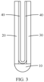
- FIG. 3 is a schematic diagram of a structure of the foldable terminal in a state of being folded in half.
- a first body 20 and a second body 30 are roughly parallel to each other, and a screen 40 is folded in a space enclosed by the first body 20, a foldable mechanism 10, and the second body 30.
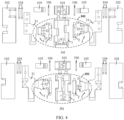
- FIG. 4 is a schematic exploded view of a structure of a foldable mechanism 10, where (a) in FIG. 4 is a schematic exploded view of a structure of the foldable mechanism 10 with a first surface upward, and (b) in FIG. 4 is a schematic exploded view of a structure of the foldable mechanism 10 with a second surface upward.
- a position of the first surface is opposite to a position of the second surface, for example, the first surface is a back surface of the foldable mechanism, and the second surface is a front surface of the foldable structure.
- FIG. 5 is a schematic diagram of an assembled structure of a foldable mechanism 10, where (a) in FIG. 5 corresponds to (a) in FIG. 4 and is a schematic diagram of an assembled structure of a foldable mechanism 10 with a first surface upward, and (b) in FIG. 5 corresponds to (b) in FIG. 4 and is a schematic diagram of an assembled structure of a foldable mechanism 10 with a second surface upward.
- the folding structure 10 includes a rotating assembly 101 and a door plate 102, where the rotating assembly 101 is a core assembly of the foldable mechanism 10 to achieve a folding function thereof.
- the rotating assembly 101 includes a base 1, rotating shafts 2, and swing arms 3, where a rotating shaft 2 and a swing arm 3 are installed on one side of the base 1, and a rotating shaft 2 and a swing arm 3 are also installed on the other side of the base 1.
- a part of the swing arm 3 is installed in the base 1, and the other part thereof extends out of the base 1.
- the door plate 102 is located on a surface of the swing arm 3.
- the door plate 102 is located on a surface of the part that is of the swing arm 3 and that extends out of the base 1.
- the door plate 102 is configured to support the screen 40.
- a surface that is of the swing arm 3 on one side of the foldable mechanism 10 and that faces away from the door plate 102 is connected to the first body 20
- a surface that is of the swing arm 3 on the other side of the foldable mechanism 10 and that faces away from the door plate 102 is connected to the second body 30, and the screen 40 is located on surfaces of the first body 20, the door plate 102 of the foldable mechanism 10, and the second body 30.
- the foldable terminal performs the folding function under the action of the foldable mechanism, and a key component of the foldable mechanism is the rotating assembly 101 that can rotate.
- the rotating assembly 101 is described in detail below.
- FIG. 6 is a schematic exploded view of a structure of the rotating assembly 101.
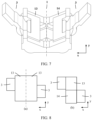
- FIG. 7 is a schematic diagram of an assembled structure of the rotating assembly 101.
- the rotating assembly includes a base 1, a rotating shaft 2, and a swing arm 3, where the swing arm 3 shown in FIG. 6 and FIG. 7 is a part of the swing arm 3 in FIG. 4 , the swing arm 3 shown in subsequent figures is also a part of the swing arm 3 in FIG. 4 , and this part is used to assemble with the rotating shaft 2 and the base 1.
- both the rotating shaft 2 and the swing arm 3 are installed in the base 1, and both the rotating shaft 2 and the swing arm 3 can rotate relative to the base 1.
- the swing arm 3 can drive the body connected thereto to rotate, thereby implementing a bending function of the foldable mechanism.
- the rotating assembly is a double swing arm type rotating assembly, with two rotating shafts 2 and two swing arms 3, one rotating shaft 2 and one swing arm 3 are installed on a first side portion 13 of the base 1, and the other rotating shaft 2 and the other swing arm 3 are installed on a second side portion 14 of the base 1.
- a position of the swing arm 3 located on the first side portion 13 and a position of the swing arm 3 located on the second side portion 14 are symmetrical with respect to a central line of the base 1.
- This design can reduce a size of the rotating assembly in an axial direction. That is, as shown in FIG. 7 , this design can reduce a length of the rotating assembly in a y-axis.
- the two swing arms 3 located on different sides of the base 1 may not be symmetrical with each other.
- a first side portion 13 and a second side portion 14 of a base 1 are still distributed left and right, but one swing arm 3 is located at an upper position of the first side portion 13, and the other swing arm 3 is located at a lower position of the second side portion 14.
- the first side portion 13 and the second side portion 14 of the base 1 are vertically distributed, but the swing arm 3 located on the first side portion 13 and the swing arm 3 located on the second side portion 14 are staggered.
- the staggering of the two swing arms 3 located on different sides of the base 1 can reduce the size in the axial direction perpendicular to the rotating assembly. That is, as shown in (b) in FIG. 8 , the design can reduce a length of the rotating assembly in an x-axis direction.
- a positional relationship between the two swing arms 3 located on different sides of the base 1 is not limited in this embodiment, and may be flexibly selected based on an actual situation.
- the swing arm 3 on the first side portion 13 of the base 1 may be connected to the first body 20, and the swing arm 3 on the second side portion 14 of the base 1 may be connected to the second body 30, so that when the two swing arms 3 rotate, the first body 20 and the second body 30 can be bent at the foldable mechanism 10.
- the rotating assembly is a double swing arm type rotating assembly.
- the rotating assembly may alternatively be a single swing arm type rotating assembly, where one rotating shaft 2 and one swing arm 3 are provided, and the rotating shaft 2 and the swing arm 3 are installed on the first side portion 13 or the second side portion 14 of the base 1.
- the swing arm 3 on one side of the base 1 may be connected to the first body 20, and the other side portion of the base 1 may be connected to the second body 30, so that when the swing arm 3 drives the first body 20 to rotate, the first body 20 may be bent relative to the second body 30.
- the rotating assembly may alternatively be a multi-swing arm type rotating assembly, and two or more rotating shafts 2 and two or more swing arms 3 are provided.
- a plurality of rotating shafts 2 and a plurality of swing arms 3 are installed on a first side portion 13 of a base 1
- a plurality of rotating shafts 2 and a plurality of swing arms 3 are installed on a second side portion 14 of the base 1, and a quantity of the swing arms 3 at the first side portion 13 may be equal or unequal to a quantity of the swing arms 3 at the second side portion 14.
- the plurality of swing arms 3 at the first side portion 13 of the base 1 are connected to the first body 20, and the plurality of swing arms 3 at the second side portion 14 of the base 1 are connected to the second body 30, so that when the swing arms 3 on the two sides of the base 1 rotate, the first body 20 and the second body 30 can be bent at the foldable mechanism 10.
- each rotating shaft 2 Regardless of how many swing arms 3 are included in the rotating assembly, a specific structure of each rotating shaft 2, a specific structure of each swing arm 3, and installation relationships between each rotating shaft 2 and the base 1 and between each swing arm 3 and the base 1 are roughly the same, and the rotating shaft 2 and the swing arm 3 on one side (for example, on the right side) of the base 1 may be used as an example for description, as shown in FIG. 10 .
- FIG. 10 is a schematic exploded view of a partial structure of a rotating assembly.
- a base 1 is provided with a rotating shaft through-hole 11 and an arc-shaped first slideway 12.
- the first slideway 12 is located at a position of the rotating shaft through-hole 11 far away from a swing arm 3.
- one end of the first slideway 12 communicates with the rotating shaft through-hole 11
- an axis L1 of the first slideway 12 is parallel to an axis L2 of the rotating shaft through-hole 11
- one end of the first slideway 12 is an end portion in a sliding direction.
- the axis L2 of the rotating shaft through-hole 11 is a straight line passing through a center of the rotating shaft through-hole 11 and in an axial direction.
- the axis L1 of the first slideway 12 is a central line of a circle where the arc-shaped first slideway 12 is located.
- a quantity of rotating shaft through-holes 11 is related to a quantity of rotating shaft 2
- a quantity of first slideways 12 is related to a quantity of swing arms 3.
- FIG. 6 for a double swing arm type rotating assembly, two rotating shafts 2 and two swing arms 3 are provided. Then the first side portion 13 and the second side portion 14 of the base 1 are each provided with a rotating shaft through-hole 11 and a first slideway 12. As shown in FIG. 6 , the first slideway 12 of the first side portion 13 is adjacent to the first slideway 12 of the second side portion 14.
- the two rotating shafts are located in the rotating shaft through-hole 11 of the first side portion 13 and the rotating shaft through-hole of the second side portion 14 respectively, and the two swing arms 3 are located in a continuous slideway 12-21 of the first side portion 13 and a continuous slideway 12-21 of the second side portion 14 respectively.
- the rotating shaft 2 is provided with an arc-shaped second slideway 21, and an axis L3 of the rotating shaft 2 is parallel to an axis L4 of the second slideway 21.
- the axis L3 of the rotating shaft 2 is a straight line passing through a center of the rotating shaft 2 and in an axial direction.
- the axis L4 of the second slideway 21 is a central line of a circle where the arc-shaped second slideway 21 is located.
- the axis L1 of the first slideway 12 the axis L2 of the rotating shaft through-hole, the axis L3 of the rotating shaft 2, and the axis L4 of the second slideway 21 are theoretically parallel to each other.
- the second slideway 21 runs through the rotating shaft 2, where the second slideway 21 runs through the rotating shaft 2, that is, as shown in FIG. 12 , one end of the second slideway 21 is located at an outer surface of the rotating shaft 2, and the other end of the second slideway 21 is also located at the outer surface of the rotating shaft 2.
- a rotating shaft 2 is rotatably installed in a rotating shaft through-hole 11 of a base 1.
- the rotating shaft 2 matches the rotating shaft through-hole 11 of the base 1.
- an outer diameter of the rotating shaft 2 is slightly less than an inner diameter of the rotating shaft through-hole 11, and a length of the rotating shaft 2 is slightly less than that of the rotating shaft through-hole 11.
- the rotating shaft 2 can be located in the rotating shaft through-hole 11, and the rotating shaft 2 can rotate in the rotating shaft through-hole 11.
- a radius of the first slideway 12 of the base 1 is equal to that of the second slideway 21 of the rotating shaft 2, and its value may be denoted as R.
- R its value
- one end of the first slideway 12 communicates with the rotating shaft through-hole 11.
- the second slideway 21 runs through the rotating shaft 2.
- the radius of the first slideway 12 is equal to that of the second slideway 21. Therefore, as shown in FIG.
- the rotating shaft 2 rotates in the rotating shaft through-hole 11 in a first direction (for example, a clockwise direction) until an end portion of the first slideway 12 is connected to an end portion of the second slideway 21, the first slideway 12 and the second slideway 21 can form a continuous slideway, and the continuous slideway may be denoted as a continuous slideway 12-21.
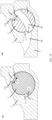
- an inner wall of the rotating shaft through-hole 11 is provided with a first limiting platform 111
- an outer surface of the rotating shaft 2 is provided with a second limiting platform 22
- the first limiting platform 111 and the second limiting platform 22 are located in a same circumferential direction, and when the rotating shaft 2 rotates in the rotating shaft through-hole 11 until the first limiting platform 111 comes into contact with the second limiting platform 22, as shown in (b) in FIG. 14 and referring to (b) in FIG. 13 , the first slideway 12 and the second slideway 21 form a continuous slideway 12-21.
- 111' in (b) in FIG. 14 indicates a projection of the first limiting platform 111
- 22' indicates a projection of the second limiting platform 22.
- a cross-sectional view shown in (a) in FIG. 14 is a schematic diagram taken at positions of the first slideway 12 and the second slideway 21, and a cross-sectional view shown in (b) in FIG. 14 is a schematic diagram not taken at the positions of the first slideway 12 and the second slideway 21.
- the second limiting platform 22 and the first limiting platform 111 are located in a same circumferential direction, so that when the rotating shaft 2 rotates in the rotating shaft through-hole 11, the second limiting platform 22 can come into contact with the first limiting platform 111, and the first limiting platform 111 prevents the rotating shaft 2 from rotating in the original direction.
- the rotating shaft 2 is prevented from rotating in the first direction (for example, the clockwise direction).
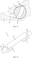
- the inner wall of the rotating shaft through-hole 11 is provided with a third limiting platform 112
- the outer surface of the rotating shaft 2 is provided with a fourth limiting platform 23, and the fourth limiting platform 23 and the third limiting platform 112 are located in a same circumferential direction.
- FIG. 14 and referring to FIG. 15 when the rotating shaft 2 rotates in the rotating shaft through-hole 11 until the third limiting platform 112 comes into contact with the fourth limiting platform 23, the rotating shaft 2 stops rotating in the original rotation direction.
- the rotating shaft 2 is prevented from rotating in the second direction (for example, the counterclockwise direction).
- a reference numeral 23' in FIG. 15 indicates a projection of the fourth limiting platform 23.
- the fourth limiting platform 23 and the third limiting platform 112 are located in a same circumferential direction, so that when the rotating shaft 2 rotates in the rotating shaft through-hole 11, the fourth limiting platform 23 can come into contact with the third limiting platform 112, and the third limiting platform 112 prevents the rotating shaft 2 from rotating in the original direction.
- the rotating shaft 2 is prevented from rotating in the counterclockwise direction.
- the contact between the third limiting platform 112 and the fourth limiting platform 23 shown in FIG. 15 can restrain the rotating shaft 2 from rotating in the second direction.
- An implementation manner of restraining the rotating shaft 2 from rotating in the second direction further includes other manners.
- a possible manner may be that when two swing arms 3 located on different sides of the base 1 collide, the rotating shaft 2 can also be restrained from rotating in the second direction.
- another possible manner may be that as shown in (c) in FIG. 18 , as introduced below, a third limiting platform 112 comes into contact with a locking portion 33 of a swing arm 3 to restrain a rotating shaft 2 from rotating in a second direction. This solution will be described below when the swing arm 3 is described.
- the foregoing limiting platforms such as the first limiting platform 111, the second limiting platform 22, the third limiting platform 112, and the fourth limiting platform 23, are formed in a similar manner, and there are a plurality of formation manners.
- the first limiting platform 111 and the third limiting platform 112 may be formed in such a manner that a cross-sectional figure of the rotating shaft through-hole 11 is of a closed structure formed by two arcs, and radii of the two arcs are different. Then two steps are formed at an intersection of the two arcs, one step may be used as the first limiting platform 111, and the other step may be used as the third limiting platform 112.
- the inner wall of the rotating shaft through-hole 11 is provided with a strip-shaped protrusion structure in the circumference direction. One end of the strip-shaped protrusion structure may be used as the first limiting platform 111, and the other end thereof may be used as the third limiting platform 112.
- the second limiting platform 22 and the fourth limiting platform 23 may be formed in such a manner that a cross-sectional figure of the rotating shaft 2 is of a closed structure formed by two arcs, and radii of the two arcs are different. Then two steps are formed at an intersection of the two arcs, one step may be used as the second limiting platform 22, and the other step may be used as the fourth limiting platform 23.
- the first limiting platform 111, the second limiting platform 22, the third limiting platform 112, and the fourth limiting platform 23 may alternatively be formed in the following manner:
- the first limiting platform 111 and the third limiting platform 112 each may be of a protrusion structure located on the inner wall surface of the rotating shaft through-hole 11 and protruding toward an axis; and the second limiting platform 22 and the fourth limiting platform 23 each may be of a protrusion structure located on the outer surface of the rotating shaft 2 and protruding away from the axis.
- a specific manner of forming the first limiting platform 111, the second limiting platform 22, the third limiting platform 112, and the fourth limiting platform 23 is not limited, provided that the following is met:
- the first limiting platform 111 and the second limiting platform 22 are located in a same circumferential direction, so that the first limiting platform 111 and the second limiting platform 22 can be in contact with each other, and when the first limiting platform 111 and the second limiting platform 22 are in contact with each other, the first slideway 12 and the second slideway 21 are connected to form a continuous slideway 12-21; and the third limiting platform 112 and the fourth limiting platform 23 are located in a same circumferential direction, so that the third limiting platform 112 and the fourth limiting platform 23 can be in contact with each other.
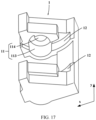
- a rotating shaft 2 may include an assembly column 24 and two support columns 25.
- the assembly column 24 is located between the two support columns 25, and an axis of the assembly column 24 and axes of the two support columns 25 are collinear.
- the second slideway 21, the second limiting platform 22, and the fourth limiting platform 23 are all arranged on the assembly column 24.
- the rotating shaft through-hole 11 includes a first-section through-hole 113 and two second-section through-holes 114.
- the first-section through-hole 113 is located between the two second-section through-holes 114, and an axis of the first-section through-hole 113 and axes of the second-section through-holes 114 are collinear.
- the first-section through-hole 113 matches the assembly column 24, and the second-section through-holes 114 match the support columns 25.
- the first limiting platform 111 and the third limiting platform 112 are arranged on an inner wall of the first-section through-hole 113.
- the assembly column 24 is located in the first-section through-hole 113, and the support columns 25 are located in the second-section through-holes 114.
- the support columns 25 with circular cross-sections are located in the second-section through-holes 114 with circular cross-sections, so that the rotating shaft 2 can smoothly rotate in the rotating shaft through-hole 11.
- the rotating assembly further includes a swing arm 3.
- a part of the swing arm 3 is installed in the base 1, and the other part is located outside the base 1 and is used to connect a body.
- the swing arm 3 includes a body connecting portion 31, a sliding portion 32, and a locking portion 33.
- the body connecting portion 31, the sliding portion 32, and the locking portion 33 are sequentially connected, and the locking portion 33 is located on a side portion of the sliding portion 32 and far away from an end portion of the body connecting portion 31.
- the body connecting portion 31 is configured to connect a body
- the sliding portion 32 and the locking portion 33 are configured to connect the base 1.
- the sliding portion 32 and the locking portion 33 are configured to be inserted into the continuous slideway 12-21 of the base 1 and slide back and forth in the continuous slideway 12-21.
- the body connecting portion 31 shown in FIG. 10 is a partial structure, and for an overall structure of the body connecting portion 31, reference may be made to FIG. 4 .
- the sliding portion 32 and the locking portion 33 are each of an arc-shaped structure and match the continuous slideway 12-21.
- a radius of a circle where the sliding portion 32 is located is equal to a radius of a circle where the locking portion 33 is located, and slightly less than a radius of a circle where the continuous slideway 12-21 is located.
- the sliding portion 32 and the locking portion 33 can be located in the continuous slideway 12-21, and can slide in the continuous slideway 12-21.
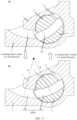
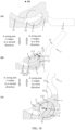
- an arc length of the locking portion 33 is less than or slightly less than an arc length of the second slideway 21. In this way, as shown in (b) in FIG. 18 , when the locking portion 33 is completely located in the second slideway 21 and the swing arm 3 rotates in the second direction relative to the base 1, as shown in (b) and (c) in FIG. 18 , the locking portion 33 can drive the rotating shaft 2 to rotate in the rotating shaft through-hole 11.
- a state shown in (a) in FIG. 18 is an initial state in which the swing arm 3 rotates in the second direction, and a state shown in (c) in FIG. 18 is a final state in which the swing arm 3 rotates in the second direction.
- an end portion that is of the locking portion 33 and that is far away from the body connecting portion 31 is in contact with an end portion that is of the continuous slideway 12-21 and that is far away from the rotating shaft through-hole 11.
- the sliding portion 32 and the locking portion 33 of the swing arm 3 slide in the continuous slideway 12-21.
- the end portion that is of the locking portion 33 of the swing arm 3 and that is close to the body connecting portion 31 is in contact with the end portion that is of the rotating shaft through-hole 11 and that is at the rotating shaft through-hole 11, the locking portion 33 is completely located in the second slideway 21.
- the swing arm 3 has already slid in the continuous slideway 12-21 to the end portion position of the continuous slideway 12-21, and cannot continue to slide in the continuous slideway 12-21 in the second direction.
- the locking portion 13 drives the rotating shaft 2 to rotate in the rotating shaft through-hole 11.
- the rotating shaft 2 stops rotating in the second direction, and the swing arm 3 also stops rotating in the second direction.
- the contact between the third limiting platform 112 and the locking portion 33 restrains the rotating shaft 2 from rotating in the rotating shaft through-hole 11 in the counterclockwise direction.
- restraining the rotating shaft 2 from rotating in the rotating shaft through-hole 11 in the counterclockwise direction may also be implemented by the contact between the third limiting platform 112 and the fourth limiting platform 23, as shown in FIG. 14 and FIG. 15 .
- the third limiting platform 112 can be configured to restrain the swing arm 3 from rotating in the second direction.
- the third limiting platform 112 may restrain the swing arm 3 from rotating in the second direction by cooperating with the fourth limiting platform 23.
- the third limiting platform 112 can also restrain the swing arm 3 from rotating in the second direction by cooperating with the locking portion 33 of the swing arm 3.
- an arc length distance d1 between the third limiting platform 112 and the fourth limiting platform 23 needs to be greater than or equal to an arc length distance d2 between the third limiting platform 112 and the locking portion 33 of the swing arm 3 (see (b) in FIG. 18 ).
- the third limiting platform 112 first comes into contact with the fourth limiting platform 23, to restrain the rotating shaft 2 from rotating in the original direction.
- the arc length distance d2 between the third limiting platform 112 and the locking portion 33 of the swing arm 3 needs to be greater than or equal to the arc length distance d1 between the third limiting platform 112 and the fourth limiting platform 23 (see (a) in FIG. 18 ).
- the third limiting platform 112 first comes into contact with the locking portion 33, to restrain the rotating shaft 2 from rotating in the original direction.
- limiting may also be implemented without the third limiting platform 112.
- the rotating shaft 2 can also be restrained from rotating in the rotating shaft through-hole 11 in the second direction.
- the above describes the process of rotation of the swing arm 3 in the second direction.
- the swing arm 3 may also rotate in the first direction opposite to the second direction, to make the swing arm 3 rotate back and forth. Reverse movement, that is, the process of rotation of the swing arm 3 in the first direction, will be described below.
- a state shown in (c) in FIG. 18 is an initial state in which the swing arm 3 rotates in the first direction, and a state shown in (a) in FIG. 18 is a final state in which the swing arm 3 rotates in the first direction.
- a rotation angle range of rotation of the swing arm 3 relative to the base 1 may be denoted as a first angle range; and when the swing arm 3 drives the rotating shaft 2 to rotate, a rotation angle range of rotation of the swing arm 3 relative to the base 1 may be denoted as a second angle range.
- the first angle range and the second angle range are two consecutive angle ranges.
- a maximum angle of the first angle range is equal to a minimum angle of the second angle range.
- the first angle range may be approximately 0° to 45°
- the second angle range may be approximately 45° to 90°.
- an included angle between the swing arm 3 and the base 1 is approximately 0°
- an included angle between the swing arm 3 and the base 1 is approximately 45°
- an included angle between the swing arm 3 and the base 1 is approximately 90°.
- first angle range and the second angle range may alternatively be flexibly divided based on an actual situation.
- An example in which the swing arm 3 rotates in an angle range between 0° and 90° may be provided in the description.
- limiting in cases where the swing arm 3 rotates to the minimum angle of the first angle range, the minimum angle of the first angle range, the minimum angle of the second angle range, and the maximum angle of the second angle range may be implemented in the following manner.
- the swing arm 3 may no longer continue driving the rotating shaft 2 to rotate in the original direction; in another manner, as shown in FIG. 15 , through the contact between the third limiting platform 112 and the fourth limiting platform 23, the swing arm 3 may no longer continue driving the rotating shaft 2 to rotate in the original direction; and in another manner, as shown in FIG. 7 , through the collision between two swing arms 3 located on different sides of the base 1, the swing arms 3 may no longer continue driving the rotating shaft 2 to rotate in the original direction.
- the rotation radius R of the swing arm 3 in the first angle range is greater than the rotation radius r of the swing arm 3 in the second angle range.
- the track length S1 of the entire process when the swing arm 3 of this application first rotates around the first axis O1 with the radius R and then rotates around the second axis O2 with the radius r is less than the track length S2 of the entire process when the swing arm 3 of existing technologies always rotates around the axis O0 with the radius R.
- the size of the rotating assembly also becomes small.
- the length of the rotating assembly is reduced by ⁇ l and a thickness is reduced by ⁇ h. Then, when the rotating assembly is applied to a foldable terminal, an occupied space in the foldable terminal can be reduced.
- h represents a thickness of the rotating assembly
- ⁇ h represents a difference between a thickness of a rotating assembly of existing technologies as an example in (a) and a thickness of a rotating assembly of this solution as an example in (b)
- ⁇ l represents a difference between a length of the rotating assembly of existing technologies as an example in (a) and a length of the rotating assembly of this solution as an example in (b).
- the swing arm 3 of the rotating assembly can switch a rotation axis and the rotation radius during the entire rotation, and the rotation radius in the first angle range is greater than that in the second angle range.
- a large rotation radius in the first angle range makes the swing arm 3 rotate relatively gently, which can reduce a pulling force on the screen from flattening to folding, thereby protecting the screen.
- a small rotation radius in the second angle range can reduce a size of the rotating assembly.
- the reduction of the size of the rotating assembly can reduce the space in the foldable mechanism that is occupied by the rotating assembly, can reduce the size of the foldable mechanism, and reduce the space in the foldable terminal that is occupied by the foldable mechanism, thereby reducing the size of the foldable terminal, so that the size of the foldable terminal can be minimized on the basis of meeting folding requirements.
- the rotation radius R of the swing arm 3 in the first angle range and the rotation radius r thereof in the second angle range are both related to a bending radius of the screen of the foldable terminal to which the rotating assembly is applied.
- a technician may select the rotation radius R of the swing arm 3 in the first angle range and the rotation radius r thereof in the second angle range based on an actual bending radius of the screen of the foldable terminal.
- the technical may flexibly design specific shapes of the base 1, the rotating shaft 2, and the swing arm 3 based on machining requirements and assembly requirements.
- the base 1 has a notch in an axial direction of the rotating shaft through-hole 11, that is, the base 1 has a notch in a y-axis direction, and the overall base 1 is I-shaped.
- the base 1 may also be I-shaped for a rotating assembly including one swing arm 3. In this way, each rotating shaft through-hole 11 is divided into two parts in the y-axis direction, so that the rotating shaft 2 is easily assembled in the rotating shaft through-hole 11 during assembly.
- the base 1 may be split in the Y-axis direction, and after the rotating shaft 2 and the swing arm 3 are assembled, the two parts split in the y-axis direction are fixedly connected to each other.
- a specific shape of the base 1 is not limited, provided that the base 1 has the following structure: a rotating shaft through-hole 11 and a first slideway 12, an inner wall of the rotating shaft through-hole 11 is provided with a first limiting platform 111 and a third limiting platform 112, the rotating shaft through-hole 11 communicates with an end of the first slideway 12, and an axis of the rotating shaft through-hole 11 is parallel to an axis of the first slideway 12.
- the rotating shaft 2 includes an assembly column 24 and two support columns 25 in an axial direction, that is, in the y-axis direction, and a second slideway 21, a second limiting platform 22, and a fourth limiting platform 23 are all arranged on the assembly column 24.
- a specific shape of the rotating shaft 2 is not limited, provided that the rotating shaft 2 has the following structure: the second slideway 21 running through the inside of the rotating shaft 2, and the second limiting platform 22 and the fourth limiting platform 23 located on the outer surface of the rotating shaft 2, the second slideway 21 corresponds to the first slideway 12, the second limiting platform 22 matches the first limiting platform 111, and the fourth limiting platform 23 matches the third limiting platform 112.
- the rotating shaft 2 has a notch in an axial direction, so that a protrusion structure of the swing arm 3 can fill the notch position of the base 1 in the axial direction.
- a specific shape of the swing arm 3 is not limited in this embodiment, provided that the swing arm 3 has the following structure: a sliding portion 32 and a locking portion 33 that match a continuous slideway 12-21.
- the locking portion 33 is located on an end portion of the sliding portion 32 and on one or two sides in the y-axis direction, so that the swing arm 3 can slide in the continuous slideway 12-21, and the locking portion 33 can limit the sliding in the continuous slideway 12-21.
- a surface of the sliding portion 32 of the swing arm 3 has a protrusion structure, so that the protrusion structure on the surface of the swing arm 3 can fill the notch position of the base 1 after the swing arm 3 passes through the rotating shaft 2 and is installed in the base 1. If the base 1 has no notch in the y-axis direction, the rotating shaft 2 may have no notch in the y-axis direction, and the surface of the swing arm 3 may have no protrusion structure.
- a swing arm of the rotating assembly when rotating in a first angle range, slides in a continuous slideway, and moves, relative to a base, circularly around a center of a circle where a first slideway is located; and when rotating in a second angle range, the swing arm drives a rotating shaft to rotate, and moves circularly around an axis of the rotating shaft relative to the base, and a rotation radius of the swing arm in the first angle range is greater than that in the second angle range.
- the swing arm of the rotating assembly can switch a rotation axis and the rotation radius during the entire rotation, and the rotation radius of the swing arm in the first angle range is large, so that the swing arm rotates relatively gently in the first angle range, which can reduce a pulling force on the screen from flattening to bending, thereby protecting the screen.
- the swing arm has a small rotation radius in the second angle range, which can reduce a length of the rotating assembly, and then reduce a space in the foldable mechanism that is occupied by the rotating assembly, and reduce a size of the foldable mechanism, thereby reducing a space in the foldable terminal that is occupied by the foldable mechanism.
- FIG. 4 and FIG. 5 are schematic diagrams of the foldable mechanism.
- the foldable mechanism not only includes the foregoing rotating assembly 101 and a door plate 102, but also includes a fastener 103, a limiting pin 104, a connecting plate 105, and a connecting shaft 106.
- a connection relationship between these components may be as follows.
- the fastener 103 may be fixedly connected to an end portion of the base 1 of the rotating assembly 101. Then the rotating assembly 101 may be assembled. After the rotating assembly 101 is assembled, the door plate 102 may be installed on a side of the fastener 103 by using the limiting pin 104, the connecting plate 105, and the connecting shaft 106.
- the limiting pin 104 is installed on a surface of the door plate 102, and a distance is reserved between the limiting pin 104 and the door plate 102.
- One side of the connecting plate 105 is rotatably installed on a side of the fastener 103 by using the connecting shaft 106, and the other side of the connecting plate 105 is inserted between the limiting pin 104 and the door plate 102.
- the connecting plate 105 can slide between the limiting pin 104 and the door plate 102 in a sliding direction perpendicular to a direction of the connecting shaft 106.
- the limiting pin 104 may be replaced by a limiting plate, the limiting plate is installed on the surface of the door plate 102, and a side of the connecting plate 105 far from the base 1 is inserted between the limiting plate and the door plate 102, and can slide left and right between the limiting plate and the door plate 102.
- the door plate 102 rotates around the connecting shaft 106 under the driving of the connecting plate 105, to rotate with the swing arm 3.
- the connecting plate 105 slides leftward or rightward relative to the door plate 102 to adjust the rotation radius of the door plate 102 to adapt to a change in the rotation radius of the swing arm 3, so that the door plate 102 does not interfere with the movement of the swing arm 3 during the rotation of the swing arm 3.
- the foldable mechanism may further include a damping mechanism, the damping mechanism blocks the rotation of the swing arm 3.
- a user needs to overcome an acting force exerted by the damping mechanism on the swing arm 3 before operating the swing arm 3 for rotating.
- the damping mechanism may be a pneumatic damping mechanism, a hydraulic damping mechanism, a spring damping mechanism, or the like.
- a specific implementation manner of the damping mechanism is not limited in this embodiment.
- the foldable mechanism may further include a synchronization mechanism, so that a plurality of swing arms 3 can rotate synchronously.
- a swing arm of the rotating assembly when rotating in a first angle range, slides in a continuous slideway, and moves, relative to a base, circularly around a center of a circle where a first slideway is located; and when rotating in a second angle range, the swing arm drives a rotating shaft to rotate, and moves circularly around an axis of the rotating shaft relative to the base, and a rotation radius of the swing arm in the first angle range is greater than that in the second angle range.
- the swing arm of the rotating assembly can switch a rotation axis and the rotation radius during the entire rotation, and the rotation radius of the swing arm in the first angle range is large, so that the swing arm rotates relatively gently in the first angle range, which can reduce a pulling force on the screen from flattening to bending, thereby protecting the screen.
- the swing arm has a small rotation radius in the second angle range, which can reduce a length of the rotating assembly, and then reduce a space in the foldable mechanism that is occupied by the rotating assembly, thereby facilitating miniaturization of the foldable mechanism. Once the size of the foldable mechanism is reduced, a space in the foldable terminal that is occupied by the foldable mechanism can be reduced.
- the foldable terminal includes a first body 20, a second body 30, a screen 40, and the foregoing foldable mechanism 10.
- the foldable mechanism 10 is connected between the first body 20 and the second body 30.
- the screen 40 is located on surfaces of the first body 20, the second body 30, and the foldable mechanism 10, and is fastened to both the first body 20 and the second body 30.
- the foldable mechanism of the foldable terminal includes the foregoing rotating assembly.
- a swing arm of the rotating assembly slides in a continuous slideway, and moves, relative to a base, circularly around a center of a circle where a first slideway is located; and when rotating in a second angle range, the swing arm drives a rotating shaft to rotate, and moves circularly around an axis of the rotating shaft relative to the base, and a rotation radius of the swing arm in the first angle range is greater than that in the second angle range.
- the swing arm of the rotating assembly can switch a rotation axis and the rotation radius during the entire rotation, and the rotation radius of the swing arm in the first angle range is large, so that the swing arm rotates relatively gently in the first angle range, which can reduce a pulling force on the screen from flattening to bending, thereby protecting the screen.
- the swing arm has a small rotation radius in the second angle range, which can reduce a length of the rotating assembly, and then reduce a space in the foldable mechanism that is occupied by the rotating assembly, and reduce a size of the foldable mechanism, thereby reducing a space in the foldable terminal that is occupied by the foldable mechanism.
Landscapes
- Engineering & Computer Science (AREA)
- Theoretical Computer Science (AREA)
- Physics & Mathematics (AREA)
- General Physics & Mathematics (AREA)
- General Engineering & Computer Science (AREA)
- Computer Hardware Design (AREA)
- Human Computer Interaction (AREA)
- Microelectronics & Electronic Packaging (AREA)
- Mechanical Engineering (AREA)
- Mathematical Physics (AREA)
- Signal Processing (AREA)
- Telephone Set Structure (AREA)
Abstract
Description
- This application claims priority to
Chinese Patent Application No. 202110345736.2, filed on March 29, 2021 - This application relates to the field of terminal technologies, and in particular, to a rotating assembly, a foldable mechanism, and a foldable terminal.
- With development of terminal technologies, a terminal is increasingly extensively used, and has become one of the most important tools in people's daily work and life. A foldable terminal is gradually favored by people because of a small occupied space and high portability.
- The foldable terminal performs a folding function mainly by using a foldable mechanism, and a main component of the foldable mechanism is a rotating assembly. The rotating assembly mainly includes a base, a rotating shaft, and a swing arm. The swing arm is rotatably connected to the base by using the rotating shaft. When the swing arm of the rotating assembly rotates relative to the base, the foldable mechanism is enabled to be folded.
- Then, when the foldable mechanism is applied to the foldable terminal, two sides of the foldable mechanism are connected to two bodies of the foldable terminal respectively. When a user moves the bodies, the swing arm can rotate around the rotating shaft, and a screen of the foldable terminal is bent at a position corresponding to the foldable mechanism. After the two bodies of the foldable terminal are folded in half, the screen forms a semicircular structure at the position corresponding to the foldable mechanism, and a radius of this semicircular structure may be referred to as a bending radius of the screen. Although the screen can be bent, the screen has poor tensile elasticity. Therefore, to protect the screen, the bending radius of the screen is usually relatively large.
- Because a rotation radius of the swing arm is related to the bending radius of the screen, when the bending radius of the screen is relatively large, the rotation radius of the swing arm also needs to be relatively large. As a result, a rotating assembly is relatively long and occupies a relatively large space in the foldable mechanism, the foldable mechanism is also relatively long, and then the foldable mechanism occupies a relatively large space in the foldable terminal.
- This application provides a rotating assembly, a foldable mechanism, and a foldable terminal, to overcome the problems with related technologies. The technical solutions are as follows.
- According to an aspect, this application provides a rotating assembly, where the rotating assembly includes a base, a rotating shaft, and a swing arm;
- the base is provided with a rotating shaft through-hole and an arc-shaped first slideway, an end of the first slideway communicates with the rotating shaft through-hole, an axis of the first slideway is parallel to an axis of the rotating shaft through-hole, the rotating shaft is provided with an arc-shaped second slideway, an axis of the rotating shaft is parallel to an axis of the second slideway, the second slideway runs through the rotating shaft, and a radius of the second slideway is equal to that of the first slideway;
- the rotating shaft is located in the rotating shaft through-hole, and the first slideway and the second slideway can be connected to each other to form a continuous slideway, and the swing arm is located in the continuous slideway and is slidable in the continuous slideway; and
- the swing arm is configured to slide in the continuous slideway when the swing arm rotates in a first angle range, and drive the rotating shaft to rotate when the swing arm rotates in a second angle range, where a rotation radius of the swing arm in the first angle range is greater than that in the second angle range.
- When a foldable mechanism with the rotating assembly is applied to a foldable terminal, the swing arm of the rotating assembly can switch a rotation axis and the rotation radius throughout the rotation, and the rotation radius in the first angle range is greater than that in the second angle range. A large rotation radius in the first angle range makes the swing arm rotate relatively gently, which can reduce a pulling force on the screen from flattening to folding, thereby protecting the screen. A small rotation radius in the second angle range can reduce a size of the rotating assembly.
- In addition, the reduction of the size of the rotating assembly can reduce the space in the foldable mechanism that is occupied by the rotating assembly, thereby reducing the size of the foldable mechanism. Once the size of the foldable mechanism is reduced, the space in the foldable terminal that is occupied by the foldable mechanism can be reduced, thereby reducing the size of the foldable terminal, so that the size of the foldable terminal can be minimized on the basis of meeting folding requirements.
- In a possible implementation, the swing arm includes a body connecting portion, a sliding portion, and a locking portion, where the body connecting portion, the sliding portion, and the locking portion are sequentially connected, and the locking portion is located on a side portion of the sliding portion and far away from an end portion of the body connecting portion; and
the sliding portion and the locking portion each have an arc-shaped structure, the sliding portion fits with the continuous slideway, and the locking portion fits with the second slideway. - In an example, the sliding portion and the locking portion each have an arc-shaped structure and fit with the continuous slideway, and the sliding portion and the locking portion can be inserted in the continuous slideway and slide in the continuous slideway.
- In a possible implementation, when a rotation angle of the swing arm is a minimum angle of the first angle range, an end portion that is of the locking portion and that is far away from the body connecting portion is in contact with an end portion that is of the first slideway and that is far away from the second slideway; or
when the rotation angle of the swing arm is a maximum angle of the first angle range, the locking portion is located in the second slideway, and an end portion that is of the locking portion and that is close to the body connecting portion is in contact with an end portion that is of the second slideway and that is far away from the first slideway. - In this way, during rotation of the swing arm from the maximum angle to the minimum angle of the first angle range, the end portion that is of the locking portion and that is far away from the body connecting portion is in contact with the end portion that is of the first slideway and that is far away from the second slideway, so that the swing arm can be restrained from continuing to slide in an original direction in the continuous slideway.
- During rotation of the swing arm from the minimum angle to the maximum angle in the first angle range, the end portion that is of the locking portion and that is close to the body connecting portion is in contact with the end portion that is of the second slideway and that is far away from the first slideway, so that the swing arm can be restrained from continuing to slide in the original direction in the continuous slideway.
- During rotation of the swing arm from a maximum angle to a minimum angle in the second angle range, contact between a first limiting platform and a second limiting platform can restrain the rotating shaft from rotating in the original direction in the rotating shaft through-hole.
- As for manners for restraining the rotating shaft from rotating in the original direction in the rotating shaft through-hole during the rotation of the swing arm from the minimum angle to the maximum angle in the second angle range, one manner may be implemented through contact between swing arms on two sides of the base, another manner may be implemented through contact between a third limiting platform and the locking portion, and still another manner may be implemented through contact between the third limiting platform and a fourth limiting platform.
- In a possible implementation, an arc length of the locking portion is less than that of the second slideway.
- In an example, the arc length of the locking portion is less than that of the second slideway, to make the locking portion completely located in the second slideway, so that when the locking portion is driving the rotating shaft to rotate, the end portion that is of the locking portion and that is far away from the body connecting portion does not interfere with the rotation of the locking portion with the rotating shaft.
- In a possible implementation, an inner wall of the rotating shaft through-hole is provided with the first limiting platform, an outer surface of the rotating shaft is provided with the second limiting platform, and the second limiting platform and the first limiting platform are located in a same circumferential direction; and
when the rotation angle of the swing arm is a minimum angle of the second angle range, the first limiting platform is in contact with the second limiting platform, and the first slideway and the second slideway can be connected to each other to form the continuous slideway. - In an example, during rotation of the swing arm from the maximum angle to the minimum angle in the second angle range, the contact between the first limiting platform and the second limiting platform can restrain the rotating shaft from rotating in the original direction in the rotating shaft through-hole, so that the first slideway and the second slideway are connected to form the continuous slideway for the swing arm to slide along the continuous slideway in a subsequent process.
- In a possible implementation, the inner wall of the rotating shaft through-hole is provided with the third limiting platform; and
the third limiting platform is configured in such a way that the third limiting platform restrains the swing arm from rotating in an original direction when the rotation angle of the swing arm changes from the minimum angle of the second angle range to a maximum angle of the second angle range. - In a possible implementation, when the rotation angle of the swing arm is the maximum angle of the second angle range, the third limiting platform is in contact with the swing arm.
- In this way, during the rotation of the swing arm from the minimum angle to the maximum angle in the second angle range, the contact between the third limiting platform and the swing arm can restrain the rotating shaft from rotating in the original direction in the rotating shaft through-hole.
- In a possible implementation, the outer surface of the rotating shaft is provided with the fourth limiting platform, and the fourth limiting platform and the third limiting platform are located in a same circumferential direction;
- an arc length distance between the third limiting platform and the fourth limiting platform is greater than or equal to an arc length distance between the third limiting platform and the swing arm; and
- when the rotation angle of the swing arm is the maximum angle of the second angle range, the third limiting platform is in contact with the fourth limiting platform.
- In this way, during the rotation of the swing arm from the minimum angle to the maximum angle in the second angle range, the contact between the third limiting platform and the fourth limiting platform can restrain the rotating shaft from rotating in the original direction in the rotating shaft through-hole.
- In a possible implementation, the first slideway is located at a position that is in the rotating shaft through-hole and that is far away from the swing arm.
- In an example, to make the swing arm first rotate in the first angle range and then rotate in the second angle range, correspondingly, the first slideway is located at a position that is in the rotating shaft through-hole and that is far away from the swing arm. In this way, during the rotation from the minimum rotation angle to the maximum rotation angle, the swing arm can first rotate in the first angle range and then rotate in the second angle range.
- In a possible implementation, the rotating shaft includes an assembly column and two support columns;
- the assembly column is located between the two support columns, the assembly column and the two support columns are coaxial, and the second slideway runs through the assembly column;
- the rotating shaft through-hole includes a first-section through-hole and two second-section through-holes, where the first-section through-hole matches the assembly column, and the second-section through-holes match the support columns; and
- the assembly column is located in the first-section through-hole, and the support columns are located in the second-section through-holes.
- In this way, the second slideway, the second limiting platform, and the fourth limiting platform of the rotating shaft are all arranged on the assembly column, and the assembly column is configured to implement assembly with the swing arm. The support columns are configured to implement assembly with the base, a cross-section of each of the support columns may be circular, and the support columns with circular cross-sections are located in the second-section through-holes with circular cross-sections, so that the rotating shaft can smoothly rotate in the rotating shaft through-hole.
- In a possible implementation, two rotating shaft and two swing arms are provided;
- a first side portion and a second side portion of the base are each provided with the rotating shaft through-hole and the first slideway;
- the two rotating shafts are located in the rotating shaft through-hole of the first side portion and the rotating shaft through-hole of the second side portion respectively; and
- the two swing arms are located in the continuous slideway of the first side portion and the continuous slideway of the second side portion respectively.
- In an example, when the rotating assembly is applied to a foldable terminal, the swing arm installed on the first side portion is connected to one body of the foldable terminal, and the swing arm installed on the second side portion is connected to the other body of the foldable terminal, to implement a folding function of the foldable terminal.
- In a possible implementation, the maximum angle of the first angle range is equal to the minimum angle of the second angle range.
- The maximum angle of the first angle range is equal to the minimum angle of the second angle range, so that the two angle ranges are connected.
- According to another aspect, a foldable mechanism is provided, where the foldable mechanism includes a door plate and the foregoing rotating assembly; and
the door plate is located on a surface of the body connecting portion of the swing arm, and is configured to support a screen of a foldable terminal at which the foldable mechanism is located. - In an example, after the rotating shaft and the swing arm are assembled in the base, the door plate may be laid on a surface of the body connecting portion of the swing arm, the door plate is rotably connected to the body connecting portion of the swing arm, and a surface that is of the body connecting portion of the swing arm and that faces away from the door plate is used to fixedly connect the body.
- In a possible implementation, the foldable mechanism further includes a fastener, a limiting pin, a connecting plate, and a connecting shaft, where
- the fastener is located on an end portion of the base of the rotating assembly;
- the limiting pin is located on a surface of the door plate, and a distance is reserved between the limiting pin and the door plate; and
- one side of the connecting plate is connected to the fastener by using the connecting shaft, the other side of the connecting plate is inserted between the limiting pin and the door plate, and the connecting plate is slidable in a direction perpendicular to the connecting shaft relative to the door plate.
- In an example, when the swing arm is switched from driving the rotating shaft to rotate to sliding in the continuous slideway, the rotation radius of the swing arm becomes larger, and the connecting plate slides in a direction away from the door plate to increase the rotation radius of the door plate, so as to adapt to the increase of the rotation radius of the swing arm. When the swing arm is switched from sliding in the continuous slideway to driving the rotating shaft to rotate, the rotation radius of the swing arm becomes smaller, and the connecting plate slides in a direction close to the door plate to reduce the rotation radius of the door plate, so as to adapt to the reduction of the rotation radius of the swing arm.
- It can be learned that during rotation of the swing arm, the door plate rotates around the connecting shaft under the driving of the connecting plate, to rotate with the swing arm. When the swing arm switches the rotation radius, the connecting plate slides left and right relative to the door plate to adjust the rotation radius of the door plate to adapt to a change in the rotation radius of the swing arm, so that the door plate does not interfere with the movement of the swing arm during the rotation of the swing arm.
- According to another aspect, a foldable terminal is further provided, where the foldable terminal includes a first body, a second body, a screen, and the foregoing foldable mechanism; and
the foldable mechanism is connected between the first body and the second body, and the screen is located on surfaces of the first body, the second body, and the foldable mechanism, and is fastened to the first body and the second body. - When the foldable mechanism with the rotating assembly is applied to the foldable terminal, when rotating in a first angle range, a swing arm of the rotating assembly slides in a continuous slideway, and moves, relative to a base, circularly around a center of a circle where a first slideway is located; and when rotating in a second angle range, the swing arm drives a rotating shaft to rotate, and moves circularly around an axis of the rotating shaft relative to the base, and a rotation radius of the swing arm in the first angle range is greater than that in the second angle range. It can be learned that the swing arm of the rotating assembly can switch a rotation axis and the rotation radius during the entire rotation, and the rotation radius of the swing arm in the first angle range is large, so that the swing arm rotates relatively gently in the first angle range, which can reduce a pulling force on the screen from flattening to bending, thereby protecting the screen. The swing arm has a small rotation radius in the second angle range, which can reduce a length of the rotating assembly, and then reduce a space in the foldable mechanism that is occupied by the rotating assembly, and reduce a size of the foldable mechanism, thereby reducing a space in the foldable terminal that is occupied by the foldable mechanism.
- In addition, the reduction of the space in the foldable terminal that is occupied by the foldable mechanism can further reduce a size of the foldable terminal, so that the size of the foldable terminal can be minimized on the basis of meeting folding requirements.
- It should be understood that the foregoing general descriptions and the following detailed descriptions are only examples and are explanatory, and cannot limit this application.
- The accompanying drawings herein are incorporated into the specification and constitute a part of the specification, illustrate embodiments that conform to this application, and are used together with the specification to explain the principles of this application. In the drawings:
-
FIG. 1 is a schematic exploded view of a structure of a foldable terminal according to an embodiment; -
FIG. 2 is a schematic diagram of a structure of a foldable terminal in a flattened state according to an embodiment; -
FIG. 3 is a schematic diagram of a structure of a foldable terminal in a state of being folded in half according to an embodiment; -
FIG. 4 is a schematic exploded view of a structure of a foldable mechanism according to an embodiment; -
FIG. 5 is a schematic diagram of an assembled structure of a foldable mechanism according to an embodiment; -
FIG. 6 is a schematic exploded view of a structure of a rotating assembly according to an embodiment; -
FIG. 7 is a schematic diagram of an assembled structure of a rotating assembly according to an embodiment; -
FIG. 8 is a schematic diagram of arrangement positions of swing arms according to an embodiment; -
FIG. 9 is a schematic diagram of arrangement positions of swing arms according to an embodiment; -
FIG. 10 is a schematic exploded view of a structure of a rotating assembly according to an embodiment; -
FIG. 11 is a schematic diagram of a cross-section of a base taken at a rotating shaft through-hole and a first slideway according to an embodiment; -
FIG. 12 is a schematic diagram of a cross-section of a rotating shaft taken at a second slideway according to an embodiment; -
FIG. 13 is a schematic diagram of a scenario in which a rotating shaft is located in a rotating shaft through-hole and rotates in the rotating shaft through-hole according to an embodiment; -
FIG. 14 is a cross-sectional view of a rotating shaft located in a rotating shaft through-hole according to an embodiment, where (a) is a schematic diagram of a cross-section taken at the rotating shaft through-hole but not at a first slideway and a second slideway, and (b) is a schematic diagram of a cross-section taken at the first slideway, the second slideway, and the rotating shaft through-hole; -
FIG. 15 is a schematic diagram showing that a rotating shaft is located in a rotating shaft through-hole and rotates until a third limiting platform comes into contact with a fourth limiting platform according to an embodiment; -
FIG. 16 is a schematic diagram of a structure of a rotating shaft according to an embodiment; -
FIG. 17 is a schematic diagram of a structure of a base according to an embodiment; -
FIG. 18 is a schematic diagram of a scenario in which a swing arm of a rotating assembly rotates according to an embodiment; and -
FIG. 19 is a schematic diagram of a rotation track of a swing arm of a rotating assembly according to an embodiment. -
- 10. Foldable mechanism; 20. First body; 30. Second body; 40. Screen;
- 101. Rotating assembly; 102. Door plate; 103. Fastener; 104. Limiting pin; 105. Connecting plate; 106. Connecting shaft;
- 1. Base; 11. Rotating shaft through-hole; 12. First slideway; 13. First side portion; 14. Second side portion; 111. First limiting platform; 112. Third limiting platform; 113. First-section through-hole; 114. Second-section through-hole;
- 2. Rotating shaft; 21. Second slideway; 22. Second limiting platform; 23. Fourth limiting platform; 24. Assembly column; 25. Support column;
- 3. Swing arm; 31. Body connecting portion; 32. Sliding portion; 33. Locking portion;
- 22'. Projection of the second limiting platform; 23'. Projection of the fourth limiting platform; 111'. Projection of the first limiting platform.
- Example embodiments are described in detail herein, and examples thereof are shown in the accompanying drawings. When the accompanying drawings are involved in the following description, unless otherwise indicated, the same numerals in different accompanying drawings indicate the same or similar elements. The implementations described in the following example embodiments do not represent all the implementations consistent with this application. On the contrary, the implementations are only examples of apparatuses and methods consistent with some aspects of this application as detailed in the appended claims.
-
FIG. 1 is a schematic exploded view of a structure of a foldable terminal according to an embodiment of this application. Although a mobile phone is used as an example inFIG. 1 , it can be understood that the foldable terminal is not limited to a mobile phone, but may alternatively be a tablet computer, a display, or the like. - As shown in
FIG 1 , the foldable terminal includes afoldable mechanism 10, afirst body 20, asecond body 30, and ascreen 40. As shown inFIG. 1 and referring toFIG. 2 , thefoldable mechanism 10 is located between thefirst body 20 and thesecond body 30, one side of thefoldable mechanism 10 is connected to thefirst body 20, and the other side of thefoldable mechanism 10 is connected to thesecond body 30. Thescreen 40 is located on surfaces of thefirst body 20, thesecond body 30, and thefoldable mechanism 10, and thescreen 40 is fastened to thefirst body 20 and thesecond body 30. Thescreen 40 is a flexible screen that can be bent. - The foldable terminal can be folded and bent under an action of the
foldable mechanism 10, to implement flattening and folding in half.FIG. 2 is a schematic diagram of a structure of the foldable terminal in a flattened state. Afirst body 20 and asecond body 30 are roughly located in a same plane, and ascreen 40 is laid on surfaces of thefirst body 20, afoldable mechanism 10, and thesecond body 30.FIG. 3 is a schematic diagram of a structure of the foldable terminal in a state of being folded in half. Afirst body 20 and asecond body 30 are roughly parallel to each other, and ascreen 40 is folded in a space enclosed by thefirst body 20, afoldable mechanism 10, and thesecond body 30. - For a specific structure of the
foldable mechanism 10, refer toFIG. 4 andFIG. 5 .FIG. 4 is a schematic exploded view of a structure of afoldable mechanism 10, where (a) inFIG. 4 is a schematic exploded view of a structure of thefoldable mechanism 10 with a first surface upward, and (b) inFIG. 4 is a schematic exploded view of a structure of thefoldable mechanism 10 with a second surface upward. A position of the first surface is opposite to a position of the second surface, for example, the first surface is a back surface of the foldable mechanism, and the second surface is a front surface of the foldable structure. -
FIG. 5 is a schematic diagram of an assembled structure of afoldable mechanism 10, where (a) inFIG. 5 corresponds to (a) inFIG. 4 and is a schematic diagram of an assembled structure of afoldable mechanism 10 with a first surface upward, and (b) inFIG. 5 corresponds to (b) inFIG. 4 and is a schematic diagram of an assembled structure of afoldable mechanism 10 with a second surface upward. - As shown in
FIG. 4 , thefolding structure 10 includes arotating assembly 101 and adoor plate 102, where therotating assembly 101 is a core assembly of thefoldable mechanism 10 to achieve a folding function thereof. As shown inFIG. 4 and referring toFIG. 5 , the rotatingassembly 101 includes abase 1, rotatingshafts 2, and swingarms 3, where arotating shaft 2 and aswing arm 3 are installed on one side of thebase 1, and arotating shaft 2 and aswing arm 3 are also installed on the other side of thebase 1. As shown in (a) inFIG. 5 , a part of theswing arm 3 is installed in thebase 1, and the other part thereof extends out of thebase 1. - As shown in
FIG. 4 and referring toFIG. 5 , thedoor plate 102 is located on a surface of theswing arm 3. For example, as shown inFIG. 5 , thedoor plate 102 is located on a surface of the part that is of theswing arm 3 and that extends out of thebase 1. As shown inFIG. 1 , thedoor plate 102 is configured to support thescreen 40. - When the
foldable mechanism 10 is applied to a foldable terminal, as shown inFIG. 5 and referring toFIG. 1 , a surface that is of theswing arm 3 on one side of thefoldable mechanism 10 and that faces away from thedoor plate 102 is connected to thefirst body 20, a surface that is of theswing arm 3 on the other side of thefoldable mechanism 10 and that faces away from thedoor plate 102 is connected to thesecond body 30, and thescreen 40 is located on surfaces of thefirst body 20, thedoor plate 102 of thefoldable mechanism 10, and thesecond body 30. - The foldable terminal performs the folding function under the action of the foldable mechanism, and a key component of the foldable mechanism is the
rotating assembly 101 that can rotate. Therotating assembly 101 is described in detail below. -
FIG. 6 is a schematic exploded view of a structure of therotating assembly 101.FIG. 7 is a schematic diagram of an assembled structure of therotating assembly 101. As shown inFIG. 6 , the rotating assembly includes abase 1, arotating shaft 2, and aswing arm 3, where theswing arm 3 shown inFIG. 6 andFIG. 7 is a part of theswing arm 3 inFIG. 4 , theswing arm 3 shown in subsequent figures is also a part of theswing arm 3 inFIG. 4 , and this part is used to assemble with therotating shaft 2 and thebase 1. - As shown in
FIG. 6 and referring toFIG. 7 , both therotating shaft 2 and theswing arm 3 are installed in thebase 1, and both therotating shaft 2 and theswing arm 3 can rotate relative to thebase 1. When rotating, theswing arm 3 can drive the body connected thereto to rotate, thereby implementing a bending function of the foldable mechanism. - As shown in
FIG. 6 , the rotating assembly is a double swing arm type rotating assembly, with tworotating shafts 2 and twoswing arms 3, one rotatingshaft 2 and oneswing arm 3 are installed on afirst side portion 13 of thebase 1, and the otherrotating shaft 2 and theother swing arm 3 are installed on asecond side portion 14 of thebase 1. In this solution, as shown inFIG. 7 , a position of theswing arm 3 located on thefirst side portion 13 and a position of theswing arm 3 located on thesecond side portion 14 are symmetrical with respect to a central line of thebase 1. This design can reduce a size of the rotating assembly in an axial direction. That is, as shown inFIG. 7 , this design can reduce a length of the rotating assembly in a y-axis. - Certainly, for the double swing arm type rotating assembly, the two
swing arms 3 located on different sides of thebase 1 may not be symmetrical with each other. For example, as shown in (a) inFIG. 8 , afirst side portion 13 and asecond side portion 14 of abase 1 are still distributed left and right, but oneswing arm 3 is located at an upper position of thefirst side portion 13, and theother swing arm 3 is located at a lower position of thesecond side portion 14. For another example, as shown in (b) inFIG. 8 , thefirst side portion 13 and thesecond side portion 14 of thebase 1 are vertically distributed, but theswing arm 3 located on thefirst side portion 13 and theswing arm 3 located on thesecond side portion 14 are staggered. The staggering of the twoswing arms 3 located on different sides of thebase 1 can reduce the size in the axial direction perpendicular to the rotating assembly. That is, as shown in (b) inFIG. 8 , the design can reduce a length of the rotating assembly in an x-axis direction. - In the solution in which the rotating assembly includes two
swing arms 3 and tworotating shafts 2, a positional relationship between the twoswing arms 3 located on different sides of thebase 1 is not limited in this embodiment, and may be flexibly selected based on an actual situation. - When the double swing arm type rotating assembly is applied to a foldable terminal, as shown in
FIG. 5 and referring toFIG. 1 , theswing arm 3 on thefirst side portion 13 of thebase 1 may be connected to thefirst body 20, and theswing arm 3 on thesecond side portion 14 of thebase 1 may be connected to thesecond body 30, so that when the twoswing arms 3 rotate, thefirst body 20 and thesecond body 30 can be bent at thefoldable mechanism 10. - In the foregoing case, the rotating assembly is a double swing arm type rotating assembly. However, in some other examples, the rotating assembly may alternatively be a single swing arm type rotating assembly, where one rotating
shaft 2 and oneswing arm 3 are provided, and therotating shaft 2 and theswing arm 3 are installed on thefirst side portion 13 or thesecond side portion 14 of thebase 1. - When the single swing arm type rotating assembly is applied to a foldable terminal, the
swing arm 3 on one side of thebase 1 may be connected to thefirst body 20, and the other side portion of thebase 1 may be connected to thesecond body 30, so that when theswing arm 3 drives thefirst body 20 to rotate, thefirst body 20 may be bent relative to thesecond body 30. - Certainly, in some other examples, as shown in
FIG. 9 , the rotating assembly may alternatively be a multi-swing arm type rotating assembly, and two or morerotating shafts 2 and two ormore swing arms 3 are provided. As shown inFIG. 9 , a plurality ofrotating shafts 2 and a plurality ofswing arms 3 are installed on afirst side portion 13 of abase 1, a plurality ofrotating shafts 2 and a plurality ofswing arms 3 are installed on asecond side portion 14 of thebase 1, and a quantity of theswing arms 3 at thefirst side portion 13 may be equal or unequal to a quantity of theswing arms 3 at thesecond side portion 14. - When the multi-swing arm type rotating assembly is applied to a foldable terminal, the plurality of
swing arms 3 at thefirst side portion 13 of thebase 1 are connected to thefirst body 20, and the plurality ofswing arms 3 at thesecond side portion 14 of thebase 1 are connected to thesecond body 30, so that when theswing arms 3 on the two sides of thebase 1 rotate, thefirst body 20 and thesecond body 30 can be bent at thefoldable mechanism 10. - Regardless of how many swing
arms 3 are included in the rotating assembly, a specific structure of eachrotating shaft 2, a specific structure of eachswing arm 3, and installation relationships between eachrotating shaft 2 and thebase 1 and between eachswing arm 3 and thebase 1 are roughly the same, and therotating shaft 2 and theswing arm 3 on one side (for example, on the right side) of thebase 1 may be used as an example for description, as shown inFIG. 10 . - An example in which the
rotating shaft 2 and theswing arm 3 are installed on thesecond side portion 14 of thebase 1 shown inFIG. 10 is used below for description, and a case where therotating shaft 2 and theswing arm 3 are installed on thefirst side portion 13 of thebase 1 is similar thereto, and therefore details are not described again. -
FIG. 10 is a schematic exploded view of a partial structure of a rotating assembly. As shown inFIG. 10 and referring toFIG. 11 , abase 1 is provided with a rotating shaft through-hole 11 and an arc-shapedfirst slideway 12. As shown inFIG. 10 , thefirst slideway 12 is located at a position of the rotating shaft through-hole 11 far away from aswing arm 3. As shown inFIG. 10 and referring toFIG. 11 , one end of thefirst slideway 12 communicates with the rotating shaft through-hole 11, an axis L1 of thefirst slideway 12 is parallel to an axis L2 of the rotating shaft through-hole 11, and one end of thefirst slideway 12 is an end portion in a sliding direction. - As shown in
FIG. 10 and referring toFIG. 11 , the axis L2 of the rotating shaft through-hole 11 is a straight line passing through a center of the rotating shaft through-hole 11 and in an axial direction. As shown inFIG. 10 and referring toFIG. 11 , the axis L1 of thefirst slideway 12 is a central line of a circle where the arc-shapedfirst slideway 12 is located. - It should be noted that a quantity of rotating shaft through-
holes 11 is related to a quantity ofrotating shaft 2, and a quantity offirst slideways 12 is related to a quantity ofswing arms 3. For example, as shown inFIG. 6 , for a double swing arm type rotating assembly, tworotating shafts 2 and twoswing arms 3 are provided. Then thefirst side portion 13 and thesecond side portion 14 of thebase 1 are each provided with a rotating shaft through-hole 11 and afirst slideway 12. As shown inFIG. 6 , thefirst slideway 12 of thefirst side portion 13 is adjacent to thefirst slideway 12 of thesecond side portion 14. In this way, in subsequent assembly, the two rotating shafts are located in the rotating shaft through-hole 11 of thefirst side portion 13 and the rotating shaft through-hole of thesecond side portion 14 respectively, and the twoswing arms 3 are located in a continuous slideway 12-21 of thefirst side portion 13 and a continuous slideway 12-21 of thesecond side portion 14 respectively. - As shown in
FIG. 10 and referring toFIG. 12 , therotating shaft 2 is provided with an arc-shapedsecond slideway 21, and an axis L3 of therotating shaft 2 is parallel to an axis L4 of thesecond slideway 21. As shown inFIG. 10 and referring toFIG. 12 , the axis L3 of therotating shaft 2 is a straight line passing through a center of therotating shaft 2 and in an axial direction. The axis L4 of thesecond slideway 21 is a central line of a circle where the arc-shapedsecond slideway 21 is located. - It should be noted that, as shown in
FIG. 10 , the axis L1 of thefirst slideway 12, the axis L2 of the rotating shaft through-hole, the axis L3 of therotating shaft 2, and the axis L4 of thesecond slideway 21 are theoretically parallel to each other. - As shown in
FIG. 10 and referring toFIG. 12 , thesecond slideway 21 runs through therotating shaft 2, where thesecond slideway 21 runs through therotating shaft 2, that is, as shown inFIG. 12 , one end of thesecond slideway 21 is located at an outer surface of therotating shaft 2, and the other end of thesecond slideway 21 is also located at the outer surface of therotating shaft 2. - As shown in
FIG. 13 , arotating shaft 2 is rotatably installed in a rotating shaft through-hole 11 of abase 1. Correspondingly, therotating shaft 2 matches the rotating shaft through-hole 11 of thebase 1. For example, an outer diameter of therotating shaft 2 is slightly less than an inner diameter of the rotating shaft through-hole 11, and a length of therotating shaft 2 is slightly less than that of the rotating shaft through-hole 11. As shown inFIG. 13 , therotating shaft 2 can be located in the rotating shaft through-hole 11, and therotating shaft 2 can rotate in the rotating shaft through-hole 11. (a) inFIG. 13 is a schematic diagram of therotating shaft 2 rotating to a position where afirst slideway 12 and asecond slideway 21 are staggered, and (b) inFIG. 13 is a schematic diagram of therotating shaft 2 rotating to a position where thefirst slideway 12 and thesecond slideway 21 are connected to each other. - As shown in
FIG. 13 , a radius of thefirst slideway 12 of thebase 1 is equal to that of thesecond slideway 21 of therotating shaft 2, and its value may be denoted as R. In this way, as shown inFIG. 11 , one end of thefirst slideway 12 communicates with the rotating shaft through-hole 11. As shown inFIG. 12 , thesecond slideway 21 runs through therotating shaft 2. As shown inFIG. 11 , the radius of thefirst slideway 12 is equal to that of thesecond slideway 21. Therefore, as shown inFIG. 13 , when therotating shaft 2 rotates in the rotating shaft through-hole 11 in a first direction (for example, a clockwise direction) until an end portion of thefirst slideway 12 is connected to an end portion of thesecond slideway 21, thefirst slideway 12 and thesecond slideway 21 can form a continuous slideway, and the continuous slideway may be denoted as a continuous slideway 12-21. - As shown in (b) in
FIG. 13 , after therotating shaft 2 rotates in the first direction (for example, the clockwise direction) until thefirst slideway 12 and thesecond slideway 21 are connected to form the continuous slide 12-21, therotating shaft 2 no longer continues rotating in the first direction. Correspondingly, as shown in (a) inFIG. 14 , an inner wall of the rotating shaft through-hole 11 is provided with a first limitingplatform 111, an outer surface of therotating shaft 2 is provided with a second limitingplatform 22, the first limitingplatform 111 and the second limitingplatform 22 are located in a same circumferential direction, and when therotating shaft 2 rotates in the rotating shaft through-hole 11 until the first limitingplatform 111 comes into contact with the second limitingplatform 22, as shown in (b) inFIG. 14 and referring to (b) inFIG. 13 , thefirst slideway 12 and thesecond slideway 21 form a continuous slideway 12-21. 111' in (b) inFIG. 14 indicates a projection of the first limitingplatform 111, and 22' indicates a projection of the second limitingplatform 22. - It should be noted that a cross-sectional view shown in (a) in
FIG. 14 is a schematic diagram taken at positions of thefirst slideway 12 and thesecond slideway 21, and a cross-sectional view shown in (b) inFIG. 14 is a schematic diagram not taken at the positions of thefirst slideway 12 and thesecond slideway 21. - As shown in
FIG. 14 , the second limitingplatform 22 and the first limitingplatform 111 are located in a same circumferential direction, so that when therotating shaft 2 rotates in the rotating shaft through-hole 11, the second limitingplatform 22 can come into contact with the first limitingplatform 111, and the first limitingplatform 111 prevents therotating shaft 2 from rotating in the original direction. For example, as shown in (b) inFIG. 14 and referring to (b) inFIG. 13 , therotating shaft 2 is prevented from rotating in the first direction (for example, the clockwise direction). - To make the
rotating shaft 2 rotate to a position in a second direction (for example, a counterclockwise direction) and then no longer continue rotating in the second direction, correspondingly, still referring toFIG. 14 , the inner wall of the rotating shaft through-hole 11 is provided with a third limitingplatform 112, the outer surface of therotating shaft 2 is provided with a fourth limitingplatform 23, and the fourth limitingplatform 23 and the third limitingplatform 112 are located in a same circumferential direction. As shown inFIG. 14 and referring toFIG. 15 , when therotating shaft 2 rotates in the rotating shaft through-hole 11 until the third limitingplatform 112 comes into contact with the fourth limitingplatform 23, therotating shaft 2 stops rotating in the original rotation direction. For example, as shown inFIG. 15 , therotating shaft 2 is prevented from rotating in the second direction (for example, the counterclockwise direction). A reference numeral 23' inFIG. 15 indicates a projection of the fourth limitingplatform 23. - As shown in
FIG. 15 , the fourth limitingplatform 23 and the third limitingplatform 112 are located in a same circumferential direction, so that when therotating shaft 2 rotates in the rotating shaft through-hole 11, the fourth limitingplatform 23 can come into contact with the third limitingplatform 112, and the third limitingplatform 112 prevents therotating shaft 2 from rotating in the original direction. For example, as shown inFIG. 15 , therotating shaft 2 is prevented from rotating in the counterclockwise direction. - The contact between the third limiting
platform 112 and the fourth limitingplatform 23 shown inFIG. 15 can restrain therotating shaft 2 from rotating in the second direction. An implementation manner of restraining therotating shaft 2 from rotating in the second direction further includes other manners. For example, referring back toFIG. 7 , a possible manner may be that when twoswing arms 3 located on different sides of thebase 1 collide, therotating shaft 2 can also be restrained from rotating in the second direction. For another example, another possible manner may be that as shown in (c) inFIG. 18 , as introduced below, a third limitingplatform 112 comes into contact with a lockingportion 33 of aswing arm 3 to restrain arotating shaft 2 from rotating in a second direction. This solution will be described below when theswing arm 3 is described. - The foregoing limiting platforms, such as the first limiting
platform 111, the second limitingplatform 22, the third limitingplatform 112, and the fourth limitingplatform 23, are formed in a similar manner, and there are a plurality of formation manners. - For example, as shown in
FIG. 14 , the first limitingplatform 111 and the third limitingplatform 112 may be formed in such a manner that a cross-sectional figure of the rotating shaft through-hole 11 is of a closed structure formed by two arcs, and radii of the two arcs are different. Then two steps are formed at an intersection of the two arcs, one step may be used as the first limitingplatform 111, and the other step may be used as the third limitingplatform 112. Alternatively, the inner wall of the rotating shaft through-hole 11 is provided with a strip-shaped protrusion structure in the circumference direction. One end of the strip-shaped protrusion structure may be used as the first limitingplatform 111, and the other end thereof may be used as the third limitingplatform 112. - Similarly, as shown in
FIG. 14 , the second limitingplatform 22 and the fourth limitingplatform 23 may be formed in such a manner that a cross-sectional figure of therotating shaft 2 is of a closed structure formed by two arcs, and radii of the two arcs are different. Then two steps are formed at an intersection of the two arcs, one step may be used as the second limitingplatform 22, and the other step may be used as the fourth limitingplatform 23. - Certainly, as for a specific forming manner, in addition to being formed in the foregoing manner, the first limiting
platform 111, the second limitingplatform 22, the third limitingplatform 112, and the fourth limitingplatform 23 may alternatively be formed in the following manner: The first limitingplatform 111 and the third limitingplatform 112 each may be of a protrusion structure located on the inner wall surface of the rotating shaft through-hole 11 and protruding toward an axis; and the second limitingplatform 22 and the fourth limitingplatform 23 each may be of a protrusion structure located on the outer surface of therotating shaft 2 and protruding away from the axis. - In this embodiment, a specific manner of forming the first limiting
platform 111, the second limitingplatform 22, the third limitingplatform 112, and the fourth limitingplatform 23 is not limited, provided that the following is met: The first limitingplatform 111 and the second limitingplatform 22 are located in a same circumferential direction, so that the first limitingplatform 111 and the second limitingplatform 22 can be in contact with each other, and when the first limitingplatform 111 and the second limitingplatform 22 are in contact with each other, thefirst slideway 12 and thesecond slideway 21 are connected to form a continuous slideway 12-21; and the third limitingplatform 112 and the fourth limitingplatform 23 are located in a same circumferential direction, so that the third limitingplatform 112 and the fourth limitingplatform 23 can be in contact with each other. - As shown in
FIG. 14 , an outer wall of therotating shaft 2 is provided with a second limitingplatform 22 and a fourth limitingplatform 23. Correspondingly, as shown inFIG. 16 , arotating shaft 2 may include anassembly column 24 and twosupport columns 25. Theassembly column 24 is located between the twosupport columns 25, and an axis of theassembly column 24 and axes of the twosupport columns 25 are collinear. Thesecond slideway 21, the second limitingplatform 22, and the fourth limitingplatform 23 are all arranged on theassembly column 24. - To match the structure of the
rotating shaft 2, correspondingly, as shown inFIG. 17 , the rotating shaft through-hole 11 includes a first-section through-hole 113 and two second-section through-holes 114. The first-section through-hole 113 is located between the two second-section through-holes 114, and an axis of the first-section through-hole 113 and axes of the second-section through-holes 114 are collinear. The first-section through-hole 113 matches theassembly column 24, and the second-section through-holes 114 match thesupport columns 25. The first limitingplatform 111 and the third limitingplatform 112 are arranged on an inner wall of the first-section through-hole 113. - In this way, after the
rotating shaft 2 is installed in the rotating shaft through-hole 11 of thebase 1, theassembly column 24 is located in the first-section through-hole 113, and thesupport columns 25 are located in the second-section through-holes 114. - In this way, the
support columns 25 with circular cross-sections are located in the second-section through-holes 114 with circular cross-sections, so that therotating shaft 2 can smoothly rotate in the rotating shaft through-hole 11. - As described above, the rotating assembly further includes a
swing arm 3. Referring toFIG. 4 andFIG. 5 , a part of theswing arm 3 is installed in thebase 1, and the other part is located outside thebase 1 and is used to connect a body. Correspondingly, as shown inFIG. 10 , theswing arm 3 includes abody connecting portion 31, a slidingportion 32, and a lockingportion 33. As shown inFIG. 10 , thebody connecting portion 31, the slidingportion 32, and the lockingportion 33 are sequentially connected, and the lockingportion 33 is located on a side portion of the slidingportion 32 and far away from an end portion of thebody connecting portion 31. - The
body connecting portion 31 is configured to connect a body, and the slidingportion 32 and the lockingportion 33 are configured to connect thebase 1. For example, the slidingportion 32 and the lockingportion 33 are configured to be inserted into the continuous slideway 12-21 of thebase 1 and slide back and forth in the continuous slideway 12-21. - It should be noted that the
body connecting portion 31 shown inFIG. 10 is a partial structure, and for an overall structure of thebody connecting portion 31, reference may be made toFIG. 4 . - To enable the sliding
portion 32 and the lockingportion 33 to slide back and forth in the continuous slideway 12-21, correspondingly, as shown inFIG. 10 , the slidingportion 32 and the lockingportion 33 are each of an arc-shaped structure and match the continuous slideway 12-21. For example, a radius of a circle where the slidingportion 32 is located is equal to a radius of a circle where the lockingportion 33 is located, and slightly less than a radius of a circle where the continuous slideway 12-21 is located. In this way, as shown inFIG. 18 , the slidingportion 32 and the lockingportion 33 can be located in the continuous slideway 12-21, and can slide in the continuous slideway 12-21. - As shown in
FIG. 18 , an arc length of the lockingportion 33 is less than or slightly less than an arc length of thesecond slideway 21. In this way, as shown in (b) inFIG. 18 , when the lockingportion 33 is completely located in thesecond slideway 21 and theswing arm 3 rotates in the second direction relative to thebase 1, as shown in (b) and (c) inFIG. 18 , the lockingportion 33 can drive therotating shaft 2 to rotate in the rotating shaft through-hole 11. - Based on the foregoing description, as shown in
FIG. 18 , during rotation of theswing arm 3 in the second direction (for example, the counterclockwise direction), the rotation process of theswing arm 3 is as follows. - A state shown in (a) in
FIG. 18 is an initial state in which theswing arm 3 rotates in the second direction, and a state shown in (c) inFIG. 18 is a final state in which theswing arm 3 rotates in the second direction. - As shown in (a) in
FIG. 18 , an end portion that is of the lockingportion 33 and that is far away from thebody connecting portion 31 is in contact with an end portion that is of the continuous slideway 12-21 and that is far away from the rotating shaft through-hole 11. When theswing arm 3 rotates in the second direction, the slidingportion 32 and the lockingportion 33 of theswing arm 3 slide in the continuous slideway 12-21. As shown in (b) inFIG. 18 , when the end portion that is of the lockingportion 33 of theswing arm 3 and that is close to thebody connecting portion 31 is in contact with the end portion that is of the rotating shaft through-hole 11 and that is at the rotating shaft through-hole 11, the lockingportion 33 is completely located in thesecond slideway 21. In this case, as shown in (b) inFIG. 18 , theswing arm 3 has already slid in the continuous slideway 12-21 to the end portion position of the continuous slideway 12-21, and cannot continue to slide in the continuous slideway 12-21 in the second direction. - When the
swing arm 3 continues rotating in the second direction, the lockingportion 13 drives therotating shaft 2 to rotate in the rotating shaft through-hole 11. As shown in (c) inFIG. 18 , when rotating until the third limitingplatform 112 comes into contact with the lockingportion 33, therotating shaft 2 stops rotating in the second direction, and theswing arm 3 also stops rotating in the second direction. - As described above, the contact between the third limiting
platform 112 and the lockingportion 33 restrains therotating shaft 2 from rotating in the rotating shaft through-hole 11 in the counterclockwise direction. - As described above, restraining the
rotating shaft 2 from rotating in the rotating shaft through-hole 11 in the counterclockwise direction may also be implemented by the contact between the third limitingplatform 112 and the fourth limitingplatform 23, as shown inFIG. 14 andFIG. 15 . - It can be learned that when the
swing arm 3 rotates in the second direction to a state shown in (c) inFIG. 18 , the third limitingplatform 112 can be configured to restrain theswing arm 3 from rotating in the second direction. For example, as shown inFIG. 14 andFIG. 15 , the third limitingplatform 112 may restrain theswing arm 3 from rotating in the second direction by cooperating with the fourth limitingplatform 23. For another example, as shown in (c) inFIG. 18 , the third limitingplatform 112 can also restrain theswing arm 3 from rotating in the second direction by cooperating with the lockingportion 33 of theswing arm 3. - When the third limiting
platform 112 cooperates with the fourth limitingplatform 23 to implement limiting, an arc length distance d1 between the third limitingplatform 112 and the fourth limiting platform 23 (see (a) inFIG. 14 ) needs to be greater than or equal to an arc length distance d2 between the third limitingplatform 112 and the lockingportion 33 of the swing arm 3 (see (b) inFIG. 18 ). In this way, during rotation of theswing arm 3 in the second direction, the third limitingplatform 112 first comes into contact with the fourth limitingplatform 23, to restrain therotating shaft 2 from rotating in the original direction. - Similarly, when the third limiting
platform 112 cooperates with the lockingportion 33 to implement limiting, the arc length distance d2 between the third limitingplatform 112 and the lockingportion 33 of the swing arm 3 (see (b) inFIG. 18 ) needs to be greater than or equal to the arc length distance d1 between the third limitingplatform 112 and the fourth limiting platform 23 (see (a) inFIG. 18 ). In this way, during rotation of theswing arm 3 in the second direction, the third limitingplatform 112 first comes into contact with the lockingportion 33, to restrain therotating shaft 2 from rotating in the original direction. - The above describes the effect of restraining the
rotating shaft 2 from rotating in the original direction by using the third limitingplatform 112. In some examples, limiting may also be implemented without the third limitingplatform 112. For example, as shown inFIG. 7 , when theswing arm 3 on the left side of thebase 1 and theswing arm 3 on the right side of thebase 1 rotate to come into contact with each other, therotating shaft 2 can also be restrained from rotating in the rotating shaft through-hole 11 in the second direction. - The above describes the process of rotation of the
swing arm 3 in the second direction. Theswing arm 3 may also rotate in the first direction opposite to the second direction, to make theswing arm 3 rotate back and forth. Reverse movement, that is, the process of rotation of theswing arm 3 in the first direction, will be described below. - A state shown in (c) in
FIG. 18 is an initial state in which theswing arm 3 rotates in the first direction, and a state shown in (a) inFIG. 18 is a final state in which theswing arm 3 rotates in the first direction. - As shown in (c) and (b) in
FIG. 18 , when theswing arm 3 drives therotating shaft 2 to rotate in the first direction until the first limitingplatform 111 and the second limitingplatform 22 come into contact with each other (seeFIG. 13 ), therotating shaft 2 stops rotating in the first direction, and in this case, thefirst slideway 12 and thesecond slideway 21 are connected to form a continuous slideway 12-21. - As shown in (b) in
FIG. 18 , when theswing arm 3 continues rotating in the first direction, the slidingportion 32 and the lockingportion 33 of theswing arm 3 slide in the continuous slideway 12-21. As shown in (a) inFIG. 18 , when the lockingportion 33 slides in the continuous slideway 12-21 to an end portion of the continuous slideway 12-21, that is, when the end portion that is of the lockingportion 33 and that is far away from thebody connecting portion 31 comes into contact with the end portion that is of thefirst slideway 12 and that is far away from thesecond slideway 21, theswing arm 3 has already slid in the continuous slideway 12-21 to the end portion position of the continuous slideway 12-21 and cannot continue sliding in the continuous slideway 12-21. - It can be learned from the rotation process of the
swing arm 3 inFIG. 18 that during rotation of theswing arm 3 relative to thebase 1, two stages are included. As shown in (a) and (b) inFIG. 18 , in one stage, the slidingportion 32 and the lockingportion 33 of theswing arm 3 slide in the continuous slideway 12-21; and as shown in (b) and (c) inFIG. 18 , in the other stage, the lockingportion 33 of theswing arm 3 drives therotating shaft 2 to rotate in the rotating shaft through-hole 11. - During sliding of the
swing arm 3 slides in the continuous slideway 12-21, a rotation angle range of rotation of theswing arm 3 relative to thebase 1 may be denoted as a first angle range; and when theswing arm 3 drives therotating shaft 2 to rotate, a rotation angle range of rotation of theswing arm 3 relative to thebase 1 may be denoted as a second angle range. - The first angle range and the second angle range are two consecutive angle ranges. For example, a maximum angle of the first angle range is equal to a minimum angle of the second angle range. For example, the first angle range may be approximately 0° to 45°, and the second angle range may be approximately 45° to 90°. For example, as shown in (a) in
FIG. 18 , an included angle between theswing arm 3 and thebase 1 is approximately 0°; as shown in (b) inFIG. 18 , an included angle between theswing arm 3 and thebase 1 is approximately 45°; and as shown in (c) inFIG. 18 , an included angle between theswing arm 3 and thebase 1 is approximately 90°. - Certainly, the first angle range and the second angle range may alternatively be flexibly divided based on an actual situation. An example in which the
swing arm 3 rotates in an angle range between 0° and 90° may be provided in the description. - Then, based on the foregoing description, limiting in cases where the
swing arm 3 rotates to the minimum angle of the first angle range, the minimum angle of the first angle range, the minimum angle of the second angle range, and the maximum angle of the second angle range may be implemented in the following manner. - As shown in (a) and (b) in
FIG. 18 , during rotation of theswing arm 3 from the maximum angle of the first angle range to the minimum angle of the first angle range, when the rotation angle of theswing arm 3 reaches the minimum angle of the first angle range through the contact between the end portion that is of the lockingportion 33 and that is far away from thebody connecting portion 31 and the end portion that is of thefirst slideway 12 and that is far away from thesecond slideway 21, theswing arm 3 no longer continues sliding in the original direction. - As shown in (a) and (b) in
FIG. 18 , during rotation of theswing arm 3 from the minimum angle of the first angle range to the maximum angle of the first angle range, when the rotation angle of theswing arm 3 reaches the maximum angle of the first angle range through the contact between the end portion that is of the lockingportion 33 that is close to thebody connecting portion 31 and the end portion that is of thesecond slideway 21 and that is far away from thefirst slideway 12, theswing arm 3 no longer continues sliding in the original direction, so that theswing arm 3 rotates in the second angle range, and theswing arm 3 drives therotating shaft 2 to rotate. - As shown in (b) and (c) in
FIG. 18 , during rotation of theswing arm 3 from the maximum angle of the second angle range to the minimum angle of the second angle range, when the rotation angle of theswing arm 3 reaches the minimum angle of the second angle range through the contact between the first limitingplatform 111 and the second limitingplatform 22, theswing arm 3 no longer drives therotating shaft 2 to rotate in the original direction, and thefirst slideway 12 and thesecond slideway 21 are just connected to form a continuous slideway 12-21, so that theswing arm 3 rotates in the first angle range, and theswing arm 3 slides in the continuous slideway 12-21. - As shown in (b) and (c) in
FIG. 18 , during rotation of theswing arm 3 from the minimum angle of the second angle range to the maximum angle of the second angle range, in one manner, as shown in (c) inFIG. 18 , through the contact between the third limitingplatform 112 and the lockingportion 33, theswing arm 3 may no longer continue driving therotating shaft 2 to rotate in the original direction; in another manner, as shown inFIG. 15 , through the contact between the third limitingplatform 112 and the fourth limitingplatform 23, theswing arm 3 may no longer continue driving therotating shaft 2 to rotate in the original direction; and in another manner, as shown inFIG. 7 , through the collision between twoswing arms 3 located on different sides of thebase 1, theswing arms 3 may no longer continue driving therotating shaft 2 to rotate in the original direction. - Still referring to (a) and (b) in
FIG. 18 , during sliding of theswing arm 3 in the continuous slideway 12-21, that is, during rotation of theswing arm 3 in the first angle range relative to thebase 1, theswing arm 3 moves circularly relative to thebase 1, and an axis of this circular movement is a center of a circle where the continuous slideway 12-21 is located. The center of the circle is also a center of a circle where thefirst slideway 12 is located, and this axis may be referred to as a first axis O1. During the circular movement of theswing arm 3 around the first axis O1, the rotation radius of theswing arm 3 is denoted as R. - As shown in (b) and (c) in
FIG. 18 , when theswing arm 3 drives therotating shaft 2 to rotate in the rotating shaft through-hole 11, that is, during rotation of theswing arm 3 in the second angle range relative to thebase 1, theswing arm 3 also moves circularly relative to thebase 1, an axis of this circular movement is a rotation center of therotating shaft 2, and the axis may be referred to as asecond axis 02. During the circular movement of theswing arm 3 around the first axis OA1, the rotation radius of theswing arm 3 is denoted as r. - The rotation radius R of the
swing arm 3 in the first angle range is greater than the rotation radius r of theswing arm 3 in the second angle range. - (a) in
FIG. 19 is a schematic diagram of a track of aswing arm 3 when in existing technologies, during rotation of theswing arm 3 from a minimum angle of a first angle range to a maximum angle of a second angle range relative to abase 1, theswing arm 3 always rotates around an axis O0 based on a rotation radius R. A length of the track may be denoted as S2. - (b) in
FIG. 19 is a schematic diagram of a track of theswing arm 3 when in this application, during rotation of theswing arm 3 from the minimum angle of the first angle range to the maximum angle of the second angle range relative to thebase 1, theswing arm 3 first rotates around a first axis O1 based on the rotation radius R and then rotates around a second axis O2 based on a rotation radius r. A length of the track may be denoted asS 1. - As shown in (a) and (b) in
FIG. 19 , during rotation of theswing arm 3 of this application and theswing arm 3 of existing technologies at a same angle relative to thebase 1, the track length S1 of the entire process when theswing arm 3 of this application first rotates around the first axis O1 with the radius R and then rotates around the second axis O2 with the radius r is less than the track length S2 of the entire process when theswing arm 3 of existing technologies always rotates around the axis O0 with the radius R. - However, when the length of the movement track of the
swing arm 3 in the rotating assembly is small, the size of the rotating assembly also becomes small. For example, the length of the rotating assembly is reduced by Δl and a thickness is reduced by Δh. Then, when the rotating assembly is applied to a foldable terminal, an occupied space in the foldable terminal can be reduced. - In
FIG. 19 , h represents a thickness of the rotating assembly, Δh represents a difference between a thickness of a rotating assembly of existing technologies as an example in (a) and a thickness of a rotating assembly of this solution as an example in (b), and Δl represents a difference between a length of the rotating assembly of existing technologies as an example in (a) and a length of the rotating assembly of this solution as an example in (b). - It should be noted that, because during folding of the foldable terminal, a screen is subjected to a relatively large acting force in an initial folding stage and is easily damaged, a relatively large rotation radius is needed, and the screen is subjected to a reduced acting force in a subsequent stage, so that the rotation radius may be reduced.
- It can be learned that when the rotating assembly is applied to a foldable terminal, the
swing arm 3 of the rotating assembly can switch a rotation axis and the rotation radius during the entire rotation, and the rotation radius in the first angle range is greater than that in the second angle range. A large rotation radius in the first angle range makes theswing arm 3 rotate relatively gently, which can reduce a pulling force on the screen from flattening to folding, thereby protecting the screen. A small rotation radius in the second angle range can reduce a size of the rotating assembly. - In addition, the reduction of the size of the rotating assembly can reduce the space in the foldable mechanism that is occupied by the rotating assembly, can reduce the size of the foldable mechanism, and reduce the space in the foldable terminal that is occupied by the foldable mechanism, thereby reducing the size of the foldable terminal, so that the size of the foldable terminal can be minimized on the basis of meeting folding requirements.
- It should be noted that the rotation radius R of the
swing arm 3 in the first angle range and the rotation radius r thereof in the second angle range are both related to a bending radius of the screen of the foldable terminal to which the rotating assembly is applied. A technician may select the rotation radius R of theswing arm 3 in the first angle range and the rotation radius r thereof in the second angle range based on an actual bending radius of the screen of the foldable terminal. - For specific shapes of the
base 1, therotating shaft 2, and theswing arm 3, in actual application of the rotating assembly, the technical may flexibly design specific shapes of thebase 1, therotating shaft 2, and theswing arm 3 based on machining requirements and assembly requirements. - For example, as shown in
FIG. 6 , thebase 1 has a notch in an axial direction of the rotating shaft through-hole 11, that is, thebase 1 has a notch in a y-axis direction, and theoverall base 1 is I-shaped. For another example, as shown inFIG. 10 , thebase 1 may also be I-shaped for a rotating assembly including oneswing arm 3. In this way, each rotating shaft through-hole 11 is divided into two parts in the y-axis direction, so that therotating shaft 2 is easily assembled in the rotating shaft through-hole 11 during assembly. In assembly, thebase 1 may be split in the Y-axis direction, and after therotating shaft 2 and theswing arm 3 are assembled, the two parts split in the y-axis direction are fixedly connected to each other. - In this embodiment, a specific shape of the
base 1 is not limited, provided that thebase 1 has the following structure: a rotating shaft through-hole 11 and afirst slideway 12, an inner wall of the rotating shaft through-hole 11 is provided with a first limitingplatform 111 and a third limitingplatform 112, the rotating shaft through-hole 11 communicates with an end of thefirst slideway 12, and an axis of the rotating shaft through-hole 11 is parallel to an axis of thefirst slideway 12. - For another example, for a specific shape of the
rotating shaft 2, as shown inFIG. 10 , therotating shaft 2 includes anassembly column 24 and twosupport columns 25 in an axial direction, that is, in the y-axis direction, and asecond slideway 21, a second limitingplatform 22, and a fourth limitingplatform 23 are all arranged on theassembly column 24. - In this embodiment, a specific shape of the
rotating shaft 2 is not limited, provided that therotating shaft 2 has the following structure: thesecond slideway 21 running through the inside of therotating shaft 2, and the second limitingplatform 22 and the fourth limitingplatform 23 located on the outer surface of therotating shaft 2, thesecond slideway 21 corresponds to thefirst slideway 12, the second limitingplatform 22 matches the first limitingplatform 111, and the fourth limitingplatform 23 matches the third limitingplatform 112. - As shown in
FIG. 6 , therotating shaft 2 has a notch in an axial direction, so that a protrusion structure of theswing arm 3 can fill the notch position of thebase 1 in the axial direction. - For another example, a specific shape of the
swing arm 3 is not limited in this embodiment, provided that theswing arm 3 has the following structure: a slidingportion 32 and a lockingportion 33 that match a continuous slideway 12-21. The lockingportion 33 is located on an end portion of the slidingportion 32 and on one or two sides in the y-axis direction, so that theswing arm 3 can slide in the continuous slideway 12-21, and the lockingportion 33 can limit the sliding in the continuous slideway 12-21. - As shown in
FIG. 6 , a surface of the slidingportion 32 of theswing arm 3 has a protrusion structure, so that the protrusion structure on the surface of theswing arm 3 can fill the notch position of thebase 1 after theswing arm 3 passes through therotating shaft 2 and is installed in thebase 1. If thebase 1 has no notch in the y-axis direction, therotating shaft 2 may have no notch in the y-axis direction, and the surface of theswing arm 3 may have no protrusion structure. - In this embodiment of this application, when rotating in a first angle range, a swing arm of the rotating assembly slides in a continuous slideway, and moves, relative to a base, circularly around a center of a circle where a first slideway is located; and when rotating in a second angle range, the swing arm drives a rotating shaft to rotate, and moves circularly around an axis of the rotating shaft relative to the base, and a rotation radius of the swing arm in the first angle range is greater than that in the second angle range. It can be learned that the swing arm of the rotating assembly can switch a rotation axis and the rotation radius during the entire rotation, and the rotation radius of the swing arm in the first angle range is large, so that the swing arm rotates relatively gently in the first angle range, which can reduce a pulling force on the screen from flattening to bending, thereby protecting the screen. The swing arm has a small rotation radius in the second angle range, which can reduce a length of the rotating assembly, and then reduce a space in the foldable mechanism that is occupied by the rotating assembly, and reduce a size of the foldable mechanism, thereby reducing a space in the foldable terminal that is occupied by the foldable mechanism.
- An embodiment of this application further provides a foldable mechanism.
FIG. 4 andFIG. 5 are schematic diagrams of the foldable mechanism. The foldable mechanism not only includes the foregoingrotating assembly 101 and adoor plate 102, but also includes afastener 103, a limitingpin 104, a connectingplate 105, and a connectingshaft 106. A connection relationship between these components may be as follows. - As shown in
FIG. 4 and referring toFIG. 5 , during assembly of the foldable mechanism, thefastener 103 may be fixedly connected to an end portion of thebase 1 of therotating assembly 101. Then therotating assembly 101 may be assembled. After therotating assembly 101 is assembled, thedoor plate 102 may be installed on a side of thefastener 103 by using the limitingpin 104, the connectingplate 105, and the connectingshaft 106. For example, the limitingpin 104 is installed on a surface of thedoor plate 102, and a distance is reserved between the limitingpin 104 and thedoor plate 102. One side of the connectingplate 105 is rotatably installed on a side of thefastener 103 by using the connectingshaft 106, and the other side of the connectingplate 105 is inserted between the limitingpin 104 and thedoor plate 102. The connectingplate 105 can slide between the limitingpin 104 and thedoor plate 102 in a sliding direction perpendicular to a direction of the connectingshaft 106. - The limiting
pin 104 may be replaced by a limiting plate, the limiting plate is installed on the surface of thedoor plate 102, and a side of the connectingplate 105 far from thebase 1 is inserted between the limiting plate and thedoor plate 102, and can slide left and right between the limiting plate and thedoor plate 102. - In this way, when the
swing arm 3 is switched from driving therotating shaft 2 to rotate to sliding in the continuous slideway 12-21, the rotation radius of theswing arm 3 becomes larger, and the connectingplate 105 slides in a direction away from thedoor plate 102 to increase the rotation radius of thedoor plate 102, so as to adapt to the increase of the rotation radius of theswing arm 3. When theswing arm 3 is switched from sliding in the continuous slideway 12-21 to driving therotating shaft 2 to rotate, the rotation radius of theswing arm 3 becomes smaller, and the connectingplate 105 slides in a direction close to thedoor plate 102 to reduce the rotation radius of thedoor plate 102, so as to adapt to the reduction of the rotation radius of theswing arm 3. - It can be learned that during rotation of the
swing arm 3, thedoor plate 102 rotates around the connectingshaft 106 under the driving of the connectingplate 105, to rotate with theswing arm 3. When theswing arm 3 switches the rotation radius, the connectingplate 105 slides leftward or rightward relative to thedoor plate 102 to adjust the rotation radius of thedoor plate 102 to adapt to a change in the rotation radius of theswing arm 3, so that thedoor plate 102 does not interfere with the movement of theswing arm 3 during the rotation of theswing arm 3. - In actual application of the foldable mechanism, to enable the
swing arm 3 to be stabilized at a position after rotating to the position, correspondingly, the foldable mechanism may further include a damping mechanism, the damping mechanism blocks the rotation of theswing arm 3. A user needs to overcome an acting force exerted by the damping mechanism on theswing arm 3 before operating theswing arm 3 for rotating. - The damping mechanism may be a pneumatic damping mechanism, a hydraulic damping mechanism, a spring damping mechanism, or the like. A specific implementation manner of the damping mechanism is not limited in this embodiment.
- In actual application of the foldable mechanism, if the foldable mechanism includes two or
more swing arms 3, the foldable mechanism may further include a synchronization mechanism, so that a plurality ofswing arms 3 can rotate synchronously. - In this embodiment of this application, when rotating in a first angle range, a swing arm of the rotating assembly slides in a continuous slideway, and moves, relative to a base, circularly around a center of a circle where a first slideway is located; and when rotating in a second angle range, the swing arm drives a rotating shaft to rotate, and moves circularly around an axis of the rotating shaft relative to the base, and a rotation radius of the swing arm in the first angle range is greater than that in the second angle range. It can be learned that when the rotating assembly is applied to a foldable terminal, the swing arm of the rotating assembly can switch a rotation axis and the rotation radius during the entire rotation, and the rotation radius of the swing arm in the first angle range is large, so that the swing arm rotates relatively gently in the first angle range, which can reduce a pulling force on the screen from flattening to bending, thereby protecting the screen. The swing arm has a small rotation radius in the second angle range, which can reduce a length of the rotating assembly, and then reduce a space in the foldable mechanism that is occupied by the rotating assembly, thereby facilitating miniaturization of the foldable mechanism. Once the size of the foldable mechanism is reduced, a space in the foldable terminal that is occupied by the foldable mechanism can be reduced.
- An embodiment of this application further provides a foldable terminal. As shown in
FIG. 1 to FIG. 3 , the foldable terminal includes afirst body 20, asecond body 30, ascreen 40, and the foregoingfoldable mechanism 10. Thefoldable mechanism 10 is connected between thefirst body 20 and thesecond body 30. Thescreen 40 is located on surfaces of thefirst body 20, thesecond body 30, and thefoldable mechanism 10, and is fastened to both thefirst body 20 and thesecond body 30. - The foldable mechanism of the foldable terminal includes the foregoing rotating assembly. When rotating in a first angle range, a swing arm of the rotating assembly slides in a continuous slideway, and moves, relative to a base, circularly around a center of a circle where a first slideway is located; and when rotating in a second angle range, the swing arm drives a rotating shaft to rotate, and moves circularly around an axis of the rotating shaft relative to the base, and a rotation radius of the swing arm in the first angle range is greater than that in the second angle range. It can be learned that the swing arm of the rotating assembly can switch a rotation axis and the rotation radius during the entire rotation, and the rotation radius of the swing arm in the first angle range is large, so that the swing arm rotates relatively gently in the first angle range, which can reduce a pulling force on the screen from flattening to bending, thereby protecting the screen. The swing arm has a small rotation radius in the second angle range, which can reduce a length of the rotating assembly, and then reduce a space in the foldable mechanism that is occupied by the rotating assembly, and reduce a size of the foldable mechanism, thereby reducing a space in the foldable terminal that is occupied by the foldable mechanism. Once the space in the foldable terminal that is occupied by the foldable mechanism is reduced, the size of the foldable terminal can be further reduced, so that the size of the foldable terminal can be minimized on the basis of meeting folding requirements.
- It should be understood that this application is not limited to the precise structures that are described above and that are shown in the accompanying drawings, and various modifications and changes may be made without departing from the scope of this application. The scope of this application is limited only by the appended claims.
Claims (15)
- A rotating assembly, wherein the rotating assembly comprises a base (1), a rotating shaft (2), and a swing arm (3), whereinthe base (1) is provided with a rotating shaft through-hole (11) and an arc-shaped first slideway (12), an end of the first slideway (12) communicates with the rotating shaft through-hole (11), an axis of the first slideway (12) is parallel to an axis of the rotating shaft through-hole (11), the rotating shaft (2) is provided with an arc-shaped second slideway (21), an axis of the rotating shaft (2) is parallel to an axis of the second slideway (21), the second slideway (21) runs through the rotating shaft (2), and a radius of the second slideway (21) is equal to that of the first slideway (12);the rotating shaft (2) is located in the rotating shaft through-hole (11), and the first slideway (12) and the second slideway (21) can be connected to each other to form a continuous slideway (12-21), and the swing arm (3) is located in the continuous slideway (12-21) and is slidable in the continuous slideway (12-21); andthe swing arm (3) is configured to slide in the continuous slideway (12-21) when the swing arm (3) rotates in a first angle range, and drive the rotating shaft (2) to rotate when the swing arm (3) rotates in a second angle range, wherein a rotation radius of the swing arm (3) in the first angle range is greater than that in the second angle range.
- The rotating assembly according to claim 1, wherein the swing arm (3) comprises a body connecting portion (31), a sliding portion (32), and a locking portion (33) that are sequentially connected, and the locking portion (33) is located on a side portion of the sliding portion (32) and far away from an end portion of the body connecting portion (31); and
the sliding portion (32) and the locking portion (33) each have an arc-shaped structure, the sliding portion (32) fits with the continuous slideway (12-21), and the locking portion (33) fits with the second slideway (21). - The rotating assembly according to claim 2, wherein when a rotation angle of the swing arm (3) is a minimum angle of the first angle range, an end portion that is of the locking portion (33) and that is far away from the body connecting portion (31) is in contact with an end portion that is of the first slideway (12) that is far away from the second slideway (21); or
when the rotation angle of the swing arm (3) is a maximum angle of the first angle range, the locking portion (33) is located in the second slideway (21), and an end portion that is of the locking portion (33) that is close to the body connecting portion (31) is in contact with an end portion that is of the second slideway (21) that is far away from the first slideway (12). - The rotating assembly according to claim 2, wherein an arc length of the locking portion (33) is less than that of the second slideway (21).
- The rotating assembly according to claim 1, wherein an inner wall of the rotating shaft through-hole (11) is provided with a first limiting platform (111), an outer surface of the rotating shaft (2) is provided with a second limiting platform (22), and the second limiting platform (22) and the first limiting platform (111) are located in a same circumferential direction; and
when the rotation angle of the swing arm (3) is a minimum angle of the second angle range, the first limiting platform (111) is in contact with the second limiting platform (22), and the first slideway (12) and the second slideway (21) can be connected to each other to form the continuous slideway (12-21). - The rotating assembly according to claim 1, wherein the inner wall of the rotating shaft through-hole (11) is provided with a third limiting platform (112); and
the third limiting platform (112) is configured in such a way that the third limiting platform (112) restrains the swing arm (3) from rotating in an original direction when the rotation angle of the swing arm (3) changes from the minimum angle of the second angle range to a maximum angle of the second angle range. - The rotating assembly according to claim 6, wherein when the rotation angle of the swing arm (3) is the maximum angle of the second angle range, the third limiting platform (112) is in contact with the swing arm (3).
- The rotating assembly according to claim 6, wherein the outer surface of the rotating shaft (2) is provided with a fourth limiting platform (23), and the fourth limiting platform (23) and the third limiting platform (112) are located in a same circumferential direction;an arc length distance between the third limiting platform (112) and the fourth limiting platform (23) is greater than or equal to an arc length distance between the third limiting platform (112) and the swing arm (3); andwhen the rotation angle of the swing arm (3) is the maximum angle of the second angle range, the third limiting platform (112) is in contact with the fourth limiting platform (23).
- The rotating assembly according to claim 1, wherein the first slideway (12) is located at a position that is in the rotating shaft through-hole (11) and that is far away from the swing arm (3).
- The rotating assembly according to claim 1, wherein the rotating shaft (2) comprises an assembly column (24) and two support columns (25);the assembly column (24) is located between the two support columns (25), the assembly column (24) and the two support columns (25) are coaxial, and the second slideway (21) runs through the assembly column (24);the rotating shaft through-hole (11) comprises a first-section through-hole (113) and two second-section through-holes (114), wherein the first-section through-hole (113) matches the assembly column (24), and the second-section through-holes (114) match the support columns (25); andthe assembly column (24) is located in the first-section through-hole (113), and the support columns (25) are located in the second-section through-holes (114).
- The rotating assembly according to any one of claims 1 to 10, wherein two rotating shaft (2) and two swing arms (3) are provided;a first side portion (13) and a second side portion (14) of the base (1) are each provided with the rotating shaft through-hole (11) and the first slideway (12);the two rotating shafts (2) are located in the rotating shaft through-hole (11) of the first side portion (13) and the rotating shaft through-hole (11) of the second side portion (14) respectively; andthe two swing arms (3) are located in the continuous slideway (12-21) of the first side portion (13) and the continuous slideway (12-21) of the second side portion (14) respectively.
- The rotating assembly according to any one of claims 1 to 10, wherein the maximum angle of the first angle range is equal to the minimum angle of the second angle range.
- A foldable mechanism, wherein the foldable mechanism comprises a door plate (102) and the rotating assembly (101) according to any one of claims 1 to 12; and
the door plate (102) is located on a surface of the body connecting portion (31) of the swing arm (3), and is configured to support a screen of a foldable terminal at which the foldable mechanism is located. - The foldable mechanism according to claim 13, wherein the foldable mechanism further comprises a fastener (103), a limiting pin (104), a connecting plate (105), and a connecting shaft (106), whereinthe fastener (103) is located on an end portion of the base (1) of the rotating assembly (101);the limiting pin (104) is located on a surface of the door plate (102), and a distance is reserved between the limiting pin (104) and the door plate (102); andone side of the connecting plate (105) is connected to the fastener (103) by using the connecting shaft (106), the other side of the connecting plate (105) is inserted between the limiting pin (104) and the door plate (102), and the connecting plate (105) is slidable in a direction perpendicular to the connecting shaft (106) relative to the door plate (102).
- A foldable terminal, wherein the foldable terminal comprises a first body (20), a second body (30), a screen (40), and the foldable mechanism (10) according to claim 13 or 14; and
the foldable mechanism (10) is connected between the first body (20) and the second body (30), and the screen (40) is located on surfaces of the first body (20), the second body (30), and the foldable mechanism (10), and is fastened to the first body (20) and the second body (30).
Applications Claiming Priority (2)
| Application Number | Priority Date | Filing Date | Title |
|---|---|---|---|
| CN202110345736.2A CN113888960B (en) | 2021-03-29 | 2021-03-29 | Rotating assembly, folding mechanism and folding terminal |
| PCT/CN2022/079032 WO2022206276A1 (en) | 2021-03-29 | 2022-03-03 | Rotating assembly, folding mechanism, and foldable terminal |
Publications (3)
| Publication Number | Publication Date |
|---|---|
| EP4230887A1 true EP4230887A1 (en) | 2023-08-23 |
| EP4230887A4 EP4230887A4 (en) | 2024-04-24 |
| EP4230887B1 EP4230887B1 (en) | 2025-02-19 |
Family
ID=79013142
Family Applications (1)
| Application Number | Title | Priority Date | Filing Date |
|---|---|---|---|
| EP22778460.0A Active EP4230887B1 (en) | 2021-03-29 | 2022-03-03 | Rotating assembly, folding mechanism, and foldable terminal |
Country Status (4)
| Country | Link |
|---|---|
| US (1) | US12349298B2 (en) |
| EP (1) | EP4230887B1 (en) |
| CN (1) | CN113888960B (en) |
| WO (1) | WO2022206276A1 (en) |
Families Citing this family (12)
| Publication number | Priority date | Publication date | Assignee | Title |
|---|---|---|---|---|
| CN113067926B (en) * | 2021-03-19 | 2023-12-15 | 维沃移动通信有限公司 | Folding mechanisms, bracket structures and electronic devices |
| CN113888960B (en) | 2021-03-29 | 2022-10-14 | 荣耀终端有限公司 | Rotating assembly, folding mechanism and folding terminal |
| CN115076218B (en) * | 2021-08-03 | 2023-04-07 | 华为技术有限公司 | Electronics and Folding Devices |
| CN116498643A (en) | 2022-01-18 | 2023-07-28 | 荣耀终端有限公司 | A rotating shaft mechanism and terminal equipment |
| CN116928200B (en) * | 2022-03-31 | 2025-08-29 | 荣耀终端股份有限公司 | Foldable mechanism and foldable terminal |
| CN119042276A (en) * | 2022-07-01 | 2024-11-29 | 荣耀终端有限公司 | Folding assembly and folding display device |
| CN117432702B (en) * | 2022-07-13 | 2024-12-27 | 荣耀终端有限公司 | Rotating shaft mechanism and foldable terminal equipment |
| CN114992229B (en) * | 2022-08-05 | 2022-12-16 | 荣耀终端有限公司 | Slewing mechanism and folding terminal |
| CN116480680B (en) * | 2023-03-20 | 2024-04-16 | 荣耀终端有限公司 | Folding mechanism and foldable mobile terminal |
| CN120017745B (en) * | 2023-11-16 | 2025-12-12 | 华为技术有限公司 | Folding mechanism and electronic equipment |
| CN120592962A (en) * | 2024-02-29 | 2025-09-05 | 荣耀终端股份有限公司 | Folding mechanism and foldable electronic device |
| CN118309981B (en) * | 2024-06-03 | 2024-08-30 | 浙江挪客运动用品股份有限公司 | Vehicle-mounted outdoor camping lamp |
Family Cites Families (31)
| Publication number | Priority date | Publication date | Assignee | Title |
|---|---|---|---|---|
| CN201199703Y (en) * | 2008-03-05 | 2009-02-25 | 段海 | Folding-type mobile telephone |
| KR101452871B1 (en) * | 2013-01-11 | 2014-10-22 | (주) 프렉코 | Foldable Flexible Display Device |
| KR102210047B1 (en) * | 2014-03-05 | 2021-02-01 | 엘지디스플레이 주식회사 | Foldable display apparatus |
| CN206112430U (en) | 2016-11-01 | 2017-04-19 | 京东方科技集团股份有限公司 | Foldable flexible screen's strutting arrangement and display device |
| JP6847445B2 (en) * | 2017-02-15 | 2021-03-24 | 株式会社ナチュラレーザ・ワン | Multi-axis hinge device and display device using this multi-axis hinge device |
| CN107155265B (en) * | 2017-05-26 | 2019-07-26 | 维沃移动通信有限公司 | Manufacturing method of rigid-flex board, rigid-flex board and mobile terminal |
| US11079807B1 (en) * | 2017-08-03 | 2021-08-03 | Apple Inc. | Friction roller hinge for electronic devices and method for making roller and spacer elements |
| CN107578707B (en) * | 2017-10-20 | 2019-09-27 | 上海天马微电子有限公司 | Flexible display panel and display device |
| TWM563489U (en) * | 2018-03-07 | 2018-07-11 | 富世達股份有限公司 | Linkage positioning mechanism and flexible electronic device |
| CN108769317B (en) * | 2018-05-31 | 2020-09-11 | 维沃移动通信有限公司 | A rotating shaft structure and mobile terminal |
| JP2020027246A (en) * | 2018-08-08 | 2020-02-20 | スガツネ工業株式会社 | Foldable display device |
| CN109451112A (en) * | 2018-11-30 | 2019-03-08 | 维沃移动通信有限公司 | Rotating connection assembly and folding mobile terminal |
| CN110213463B (en) * | 2018-12-26 | 2021-04-09 | 华为终端有限公司 | Camera module and mobile terminal |
| KR102587589B1 (en) * | 2019-02-19 | 2023-10-12 | 삼성전자주식회사 | A hinge structure and an electronic device comprising the same |
| US11337321B2 (en) * | 2019-02-28 | 2022-05-17 | Guangdong Oppo Mobile Telecommunications Corp., Ltd. | Foldable terminal |
| CN111692196B (en) | 2019-03-15 | 2021-10-22 | 华为技术有限公司 | A rotating shaft mechanism and mobile terminal |
| US11567542B2 (en) * | 2019-03-18 | 2023-01-31 | Apple Inc. | Hinges for electronic devices and accessory devices |
| KR102706486B1 (en) * | 2019-06-03 | 2024-09-13 | 삼성디스플레이 주식회사 | Foldable display device |
| CN110273915B (en) * | 2019-06-25 | 2020-10-09 | 昆山国显光电有限公司 | Strutting arrangement, folding display module assembly and display device of flexible screen |
| TWI693352B (en) * | 2019-06-25 | 2020-05-11 | 富世達股份有限公司 | Folding screen device and hinge mechanism |
| CN112153188B (en) | 2019-06-28 | 2021-12-03 | 华为技术有限公司 | Folding terminal |
| CN110430294B (en) * | 2019-06-28 | 2021-07-27 | 江西沃格光电股份有限公司 | Bending components, carriers and electronic equipment |
| CN110442196B (en) | 2019-07-30 | 2025-05-06 | 华为技术有限公司 | Rotating mechanism, folding display terminal |
| TWI723483B (en) * | 2019-08-01 | 2021-04-01 | 元太科技工業股份有限公司 | Display device |
| CN112306149B (en) | 2019-08-02 | 2023-07-14 | 比亚迪股份有限公司 | Folding device and mobile terminal for flexible screen |
| CN210041901U (en) * | 2019-08-30 | 2020-02-07 | Oppo广东移动通信有限公司 | Electronic equipment |
| CN114374757B (en) | 2019-08-30 | 2025-07-15 | Oppo广东移动通信有限公司 | Electronic devices and foldable components |
| CN112081815B (en) * | 2020-09-16 | 2025-06-13 | 珠海格力电器股份有限公司 | Folding hinge and electronic equipment |
| CN212486550U (en) * | 2020-09-21 | 2021-02-05 | 珠海格力电器股份有限公司 | Folding hinge mechanism and foldable terminal equipment |
| CN114095592B (en) * | 2021-03-15 | 2022-11-25 | 荣耀终端有限公司 | Folding mechanism and mobile terminal |
| CN113888960B (en) | 2021-03-29 | 2022-10-14 | 荣耀终端有限公司 | Rotating assembly, folding mechanism and folding terminal |
-
2021
- 2021-03-29 CN CN202110345736.2A patent/CN113888960B/en active Active
-
2022
- 2022-03-03 US US18/254,092 patent/US12349298B2/en active Active
- 2022-03-03 EP EP22778460.0A patent/EP4230887B1/en active Active
- 2022-03-03 WO PCT/CN2022/079032 patent/WO2022206276A1/en not_active Ceased
Also Published As
| Publication number | Publication date |
|---|---|
| CN113888960A (en) | 2022-01-04 |
| US20240098915A1 (en) | 2024-03-21 |
| EP4230887A4 (en) | 2024-04-24 |
| WO2022206276A1 (en) | 2022-10-06 |
| EP4230887B1 (en) | 2025-02-19 |
| US12349298B2 (en) | 2025-07-01 |
| CN113888960B (en) | 2022-10-14 |
Similar Documents
| Publication | Publication Date | Title |
|---|---|---|
| EP4230887B1 (en) | Rotating assembly, folding mechanism, and foldable terminal | |
| US11977421B2 (en) | Foldable hinge and electronic device | |
| US6115886A (en) | Hinge apparatus | |
| JP4731539B2 (en) | Hinge mechanism | |
| EP1630430B1 (en) | Two-axis hinge with rotation limiting mechanism | |
| US8091180B2 (en) | Hinge assembly | |
| EP4215767B1 (en) | Folding mechanism and terminal device | |
| EP4318177A1 (en) | Hinge assembly and electronic device | |
| EP4495443B1 (en) | Hinge mechanism and electronic device | |
| CN112153188B (en) | Folding terminal | |
| EP4134782A1 (en) | Hinge assembly and electronic device | |
| CN101389197A (en) | Hinge for collapsible electronic device and the collapsible electronic device | |
| KR20050039579A (en) | Hinge for a portable terminal | |
| EP4417826B1 (en) | Rotary shaft mechanism and electronic apparatus | |
| CN119866410A (en) | Rotating mechanism and foldable electronic device | |
| CN209724953U (en) | Pivot structure and electronic equipment | |
| KR20230090876A (en) | Hinge device of in-out foldable mobile device using flexible display panel | |
| JP3697339B2 (en) | Hinge device | |
| CN119496842B (en) | Foldable mechanisms and foldable terminals | |
| CN220302544U (en) | Rotating shaft mechanism and foldable electronic equipment | |
| CN111095158B (en) | A device with opening and closing performance | |
| CN215521601U (en) | Double-shaft hinge device and electronic equipment | |
| CN119755188A (en) | Hinge assembly and electronic device | |
| CN121952965A (en) | Hinge and foldable electronic device | |
| JP2010021711A (en) | Portable electronic apparatus |
Legal Events
| Date | Code | Title | Description |
|---|---|---|---|
| STAA | Information on the status of an ep patent application or granted ep patent |
Free format text: STATUS: THE INTERNATIONAL PUBLICATION HAS BEEN MADE |
|
| PUAI | Public reference made under article 153(3) epc to a published international application that has entered the european phase |
Free format text: ORIGINAL CODE: 0009012 |
|
| STAA | Information on the status of an ep patent application or granted ep patent |
Free format text: STATUS: REQUEST FOR EXAMINATION WAS MADE |
|
| 17P | Request for examination filed |
Effective date: 20230519 |
|
| AK | Designated contracting states |
Kind code of ref document: A1 Designated state(s): AL AT BE BG CH CY CZ DE DK EE ES FI FR GB GR HR HU IE IS IT LI LT LU LV MC MK MT NL NO PL PT RO RS SE SI SK SM TR |
|
| REG | Reference to a national code |
Ref country code: DE Ref legal event code: R079 Free format text: PREVIOUS MAIN CLASS: F16C0011040000 Ipc: H04M0001020000 Ref document number: 602022010926 Country of ref document: DE |
|
| A4 | Supplementary search report drawn up and despatched |
Effective date: 20240325 |
|
| RIC1 | Information provided on ipc code assigned before grant |
Ipc: F16C 11/04 20060101ALI20240319BHEP Ipc: G09F 9/30 20060101ALI20240319BHEP Ipc: G06F 1/16 20060101ALI20240319BHEP Ipc: H04M 1/02 20060101AFI20240319BHEP |
|
| DAV | Request for validation of the european patent (deleted) | ||
| DAX | Request for extension of the european patent (deleted) | ||
| GRAP | Despatch of communication of intention to grant a patent |
Free format text: ORIGINAL CODE: EPIDOSNIGR1 |
|
| STAA | Information on the status of an ep patent application or granted ep patent |
Free format text: STATUS: GRANT OF PATENT IS INTENDED |
|
| RIC1 | Information provided on ipc code assigned before grant |
Ipc: F16C 11/04 20060101ALI20240913BHEP Ipc: G09F 9/30 20060101ALI20240913BHEP Ipc: G06F 1/16 20060101ALI20240913BHEP Ipc: H04M 1/02 20060101AFI20240913BHEP |
|
| INTG | Intention to grant announced |
Effective date: 20240927 |
|
| GRAS | Grant fee paid |
Free format text: ORIGINAL CODE: EPIDOSNIGR3 |
|
| GRAA | (expected) grant |
Free format text: ORIGINAL CODE: 0009210 |
|
| STAA | Information on the status of an ep patent application or granted ep patent |
Free format text: STATUS: THE PATENT HAS BEEN GRANTED |
|
| AK | Designated contracting states |
Kind code of ref document: B1 Designated state(s): AL AT BE BG CH CY CZ DE DK EE ES FI FR GB GR HR HU IE IS IT LI LT LU LV MC MK MT NL NO PL PT RO RS SE SI SK SM TR |
|
| REG | Reference to a national code |
Ref country code: GB Ref legal event code: FG4D |
|
| REG | Reference to a national code |
Ref country code: CH Ref legal event code: EP |
|
| REG | Reference to a national code |
Ref country code: IE Ref legal event code: FG4D |
|
| REG | Reference to a national code |
Ref country code: DE Ref legal event code: R096 Ref document number: 602022010926 Country of ref document: DE |
|
| REG | Reference to a national code |
Ref country code: NL Ref legal event code: FP |
|
| PGFP | Annual fee paid to national office [announced via postgrant information from national office to epo] |
Ref country code: AT Payment date: 20250417 Year of fee payment: 4 |
|
| PG25 | Lapsed in a contracting state [announced via postgrant information from national office to epo] |
Ref country code: RS Free format text: LAPSE BECAUSE OF FAILURE TO SUBMIT A TRANSLATION OF THE DESCRIPTION OR TO PAY THE FEE WITHIN THE PRESCRIBED TIME-LIMIT Effective date: 20250519 |
|
| PG25 | Lapsed in a contracting state [announced via postgrant information from national office to epo] |
Ref country code: FI Free format text: LAPSE BECAUSE OF FAILURE TO SUBMIT A TRANSLATION OF THE DESCRIPTION OR TO PAY THE FEE WITHIN THE PRESCRIBED TIME-LIMIT Effective date: 20250219 |
|
| PG25 | Lapsed in a contracting state [announced via postgrant information from national office to epo] |
Ref country code: PL Free format text: LAPSE BECAUSE OF FAILURE TO SUBMIT A TRANSLATION OF THE DESCRIPTION OR TO PAY THE FEE WITHIN THE PRESCRIBED TIME-LIMIT Effective date: 20250219 |
|
| PG25 | Lapsed in a contracting state [announced via postgrant information from national office to epo] |
Ref country code: ES Free format text: LAPSE BECAUSE OF FAILURE TO SUBMIT A TRANSLATION OF THE DESCRIPTION OR TO PAY THE FEE WITHIN THE PRESCRIBED TIME-LIMIT Effective date: 20250219 |
|
| REG | Reference to a national code |
Ref country code: LT Ref legal event code: MG9D |
|
| PG25 | Lapsed in a contracting state [announced via postgrant information from national office to epo] |
Ref country code: IS Free format text: LAPSE BECAUSE OF FAILURE TO SUBMIT A TRANSLATION OF THE DESCRIPTION OR TO PAY THE FEE WITHIN THE PRESCRIBED TIME-LIMIT Effective date: 20250619 Ref country code: NO Free format text: LAPSE BECAUSE OF FAILURE TO SUBMIT A TRANSLATION OF THE DESCRIPTION OR TO PAY THE FEE WITHIN THE PRESCRIBED TIME-LIMIT Effective date: 20250519 |
|
| PG25 | Lapsed in a contracting state [announced via postgrant information from national office to epo] |
Ref country code: HR Free format text: LAPSE BECAUSE OF FAILURE TO SUBMIT A TRANSLATION OF THE DESCRIPTION OR TO PAY THE FEE WITHIN THE PRESCRIBED TIME-LIMIT Effective date: 20250219 |
|
| PG25 | Lapsed in a contracting state [announced via postgrant information from national office to epo] |
Ref country code: LV Free format text: LAPSE BECAUSE OF FAILURE TO SUBMIT A TRANSLATION OF THE DESCRIPTION OR TO PAY THE FEE WITHIN THE PRESCRIBED TIME-LIMIT Effective date: 20250219 Ref country code: PT Free format text: LAPSE BECAUSE OF FAILURE TO SUBMIT A TRANSLATION OF THE DESCRIPTION OR TO PAY THE FEE WITHIN THE PRESCRIBED TIME-LIMIT Effective date: 20250620 |
|
| PG25 | Lapsed in a contracting state [announced via postgrant information from national office to epo] |
Ref country code: GR Free format text: LAPSE BECAUSE OF FAILURE TO SUBMIT A TRANSLATION OF THE DESCRIPTION OR TO PAY THE FEE WITHIN THE PRESCRIBED TIME-LIMIT Effective date: 20250520 Ref country code: BG Free format text: LAPSE BECAUSE OF FAILURE TO SUBMIT A TRANSLATION OF THE DESCRIPTION OR TO PAY THE FEE WITHIN THE PRESCRIBED TIME-LIMIT Effective date: 20250219 |
|
| PG25 | Lapsed in a contracting state [announced via postgrant information from national office to epo] |
Ref country code: AT Free format text: LAPSE BECAUSE OF FAILURE TO SUBMIT A TRANSLATION OF THE DESCRIPTION OR TO PAY THE FEE WITHIN THE PRESCRIBED TIME-LIMIT Effective date: 20250219 |
|
| REG | Reference to a national code |
Ref country code: AT Ref legal event code: MK05 Ref document number: 1769460 Country of ref document: AT Kind code of ref document: T Effective date: 20250219 |
|
| PG25 | Lapsed in a contracting state [announced via postgrant information from national office to epo] |
Ref country code: SE Free format text: LAPSE BECAUSE OF FAILURE TO SUBMIT A TRANSLATION OF THE DESCRIPTION OR TO PAY THE FEE WITHIN THE PRESCRIBED TIME-LIMIT Effective date: 20250219 |
|
| PG25 | Lapsed in a contracting state [announced via postgrant information from national office to epo] |
Ref country code: SM Free format text: LAPSE BECAUSE OF FAILURE TO SUBMIT A TRANSLATION OF THE DESCRIPTION OR TO PAY THE FEE WITHIN THE PRESCRIBED TIME-LIMIT Effective date: 20250219 |
|
| PG25 | Lapsed in a contracting state [announced via postgrant information from national office to epo] |
Ref country code: DK Free format text: LAPSE BECAUSE OF FAILURE TO SUBMIT A TRANSLATION OF THE DESCRIPTION OR TO PAY THE FEE WITHIN THE PRESCRIBED TIME-LIMIT Effective date: 20250219 |
|
| PG25 | Lapsed in a contracting state [announced via postgrant information from national office to epo] |
Ref country code: IT Free format text: LAPSE BECAUSE OF FAILURE TO SUBMIT A TRANSLATION OF THE DESCRIPTION OR TO PAY THE FEE WITHIN THE PRESCRIBED TIME-LIMIT Effective date: 20250219 |
|
| PG25 | Lapsed in a contracting state [announced via postgrant information from national office to epo] |
Ref country code: CZ Free format text: LAPSE BECAUSE OF FAILURE TO SUBMIT A TRANSLATION OF THE DESCRIPTION OR TO PAY THE FEE WITHIN THE PRESCRIBED TIME-LIMIT Effective date: 20250219 Ref country code: EE Free format text: LAPSE BECAUSE OF FAILURE TO SUBMIT A TRANSLATION OF THE DESCRIPTION OR TO PAY THE FEE WITHIN THE PRESCRIBED TIME-LIMIT Effective date: 20250219 |
|
| PG25 | Lapsed in a contracting state [announced via postgrant information from national office to epo] |
Ref country code: RO Free format text: LAPSE BECAUSE OF FAILURE TO SUBMIT A TRANSLATION OF THE DESCRIPTION OR TO PAY THE FEE WITHIN THE PRESCRIBED TIME-LIMIT Effective date: 20250219 |
|
| REG | Reference to a national code |
Ref country code: CH Ref legal event code: H13 Free format text: ST27 STATUS EVENT CODE: U-0-0-H10-H13 (AS PROVIDED BY THE NATIONAL OFFICE) Effective date: 20251023 |
|
| PG25 | Lapsed in a contracting state [announced via postgrant information from national office to epo] |
Ref country code: SK Free format text: LAPSE BECAUSE OF FAILURE TO SUBMIT A TRANSLATION OF THE DESCRIPTION OR TO PAY THE FEE WITHIN THE PRESCRIBED TIME-LIMIT Effective date: 20250219 |
|
| PG25 | Lapsed in a contracting state [announced via postgrant information from national office to epo] |
Ref country code: LU Free format text: LAPSE BECAUSE OF NON-PAYMENT OF DUE FEES Effective date: 20250303 |
|
| REG | Reference to a national code |
Ref country code: DE Ref legal event code: R097 Ref document number: 602022010926 Country of ref document: DE |
|
| REG | Reference to a national code |
Ref country code: BE Ref legal event code: MM Effective date: 20250331 |
|
| PG25 | Lapsed in a contracting state [announced via postgrant information from national office to epo] |
Ref country code: MC Free format text: LAPSE BECAUSE OF FAILURE TO SUBMIT A TRANSLATION OF THE DESCRIPTION OR TO PAY THE FEE WITHIN THE PRESCRIBED TIME-LIMIT Effective date: 20250219 |
|
| PLBE | No opposition filed within time limit |
Free format text: ORIGINAL CODE: 0009261 |
|
| STAA | Information on the status of an ep patent application or granted ep patent |
Free format text: STATUS: NO OPPOSITION FILED WITHIN TIME LIMIT |
|
| PG25 | Lapsed in a contracting state [announced via postgrant information from national office to epo] |
Ref country code: FR Free format text: LAPSE BECAUSE OF NON-PAYMENT OF DUE FEES Effective date: 20250419 |
|
| PG25 | Lapsed in a contracting state [announced via postgrant information from national office to epo] |
Ref country code: BE Free format text: LAPSE BECAUSE OF NON-PAYMENT OF DUE FEES Effective date: 20250331 |
|
| PG25 | Lapsed in a contracting state [announced via postgrant information from national office to epo] |
Ref country code: CH Free format text: LAPSE BECAUSE OF NON-PAYMENT OF DUE FEES Effective date: 20250331 |
|
| PG25 | Lapsed in a contracting state [announced via postgrant information from national office to epo] |
Ref country code: IE Free format text: LAPSE BECAUSE OF NON-PAYMENT OF DUE FEES Effective date: 20250303 |
|
| 26N | No opposition filed |
Effective date: 20251120 |
|
| PGFP | Annual fee paid to national office [announced via postgrant information from national office to epo] |
Ref country code: NL Payment date: 20260213 Year of fee payment: 5 |
|
| PGFP | Annual fee paid to national office [announced via postgrant information from national office to epo] |
Ref country code: GB Payment date: 20260202 Year of fee payment: 5 |
|
| PGFP | Annual fee paid to national office [announced via postgrant information from national office to epo] |
Ref country code: DE Payment date: 20260204 Year of fee payment: 5 |