EP4230824A2 - Binding machine - Google Patents
Binding machine Download PDFInfo
- Publication number
- EP4230824A2 EP4230824A2 EP23151267.4A EP23151267A EP4230824A2 EP 4230824 A2 EP4230824 A2 EP 4230824A2 EP 23151267 A EP23151267 A EP 23151267A EP 4230824 A2 EP4230824 A2 EP 4230824A2
- Authority
- EP
- European Patent Office
- Prior art keywords
- wire
- feed
- rotation
- feed gear
- state
- Prior art date
- Legal status (The legal status is an assumption and is not a legal conclusion. Google has not performed a legal analysis and makes no representation as to the accuracy of the status listed.)
- Pending
Links
Images







Classifications
-
- B—PERFORMING OPERATIONS; TRANSPORTING
- B65—CONVEYING; PACKING; STORING; HANDLING THIN OR FILAMENTARY MATERIAL
- B65B—MACHINES, APPARATUS OR DEVICES FOR, OR METHODS OF, PACKAGING ARTICLES OR MATERIALS; UNPACKING
- B65B13/00—Bundling articles
- B65B13/18—Details of, or auxiliary devices used in, bundling machines or bundling tools
- B65B13/24—Securing ends of binding material
- B65B13/28—Securing ends of binding material by twisting
-
- E—FIXED CONSTRUCTIONS
- E04—BUILDING
- E04G—SCAFFOLDING; FORMS; SHUTTERING; BUILDING IMPLEMENTS OR AIDS, OR THEIR USE; HANDLING BUILDING MATERIALS ON THE SITE; REPAIRING, BREAKING-UP OR OTHER WORK ON EXISTING BUILDINGS
- E04G21/00—Preparing, conveying, or working-up building materials or building elements in situ; Other devices or measures for constructional work
- E04G21/12—Mounting of reinforcing inserts; Prestressing
- E04G21/122—Machines for joining reinforcing bars
- E04G21/123—Wire twisting tools
-
- B—PERFORMING OPERATIONS; TRANSPORTING
- B65—CONVEYING; PACKING; STORING; HANDLING THIN OR FILAMENTARY MATERIAL
- B65B—MACHINES, APPARATUS OR DEVICES FOR, OR METHODS OF, PACKAGING ARTICLES OR MATERIALS; UNPACKING
- B65B13/00—Bundling articles
- B65B13/18—Details of, or auxiliary devices used in, bundling machines or bundling tools
- B65B13/185—Details of tools
- B65B13/187—Motor means
-
- B—PERFORMING OPERATIONS; TRANSPORTING
- B65—CONVEYING; PACKING; STORING; HANDLING THIN OR FILAMENTARY MATERIAL
- B65B—MACHINES, APPARATUS OR DEVICES FOR, OR METHODS OF, PACKAGING ARTICLES OR MATERIALS; UNPACKING
- B65B13/00—Bundling articles
- B65B13/18—Details of, or auxiliary devices used in, bundling machines or bundling tools
- B65B13/22—Means for controlling tension of binding means
-
- B—PERFORMING OPERATIONS; TRANSPORTING
- B65—CONVEYING; PACKING; STORING; HANDLING THIN OR FILAMENTARY MATERIAL
- B65B—MACHINES, APPARATUS OR DEVICES FOR, OR METHODS OF, PACKAGING ARTICLES OR MATERIALS; UNPACKING
- B65B13/00—Bundling articles
- B65B13/18—Details of, or auxiliary devices used in, bundling machines or bundling tools
- B65B13/24—Securing ends of binding material
- B65B13/28—Securing ends of binding material by twisting
- B65B13/285—Hand tools
Definitions
- the present disclosure relates to a binding machine that binds objects to be bound such as reinforcing bars with a wire.
- Reinforcing bars are used in concrete structures to improve the strength, and are bound with wires such that the reinforcing bars do not deviate from a predetermined position when concrete is poured.
- a technique is proposed in the related art, in which a binding machine called a reinforcing bar binding machine winds a wire around two or more reinforcing bars, twists the wire wound around the reinforcing bars, and binds the two or more reinforcing bars with the wire.
- the binding machine includes a binding wire feeding mechanism that feeds a wire wound on a reel and winds the wire around reinforcing bars, a gripping mechanism that grips the wire wound around the reinforcing bars, and a binding wire twisting mechanism that twists the wire by rotationally driving the gripping mechanism, and a trigger operation causes the binding wire feeding mechanism, the gripping mechanism and the binding wire twisting mechanism to operate in sequence to perform one cycle of binding operation.
- reinforcing bars When reinforcing bars are bound with a wire, if the binding is loose, the reinforcing bars are deviated from one another, and therefore, it is required to firmly hold the reinforcing bars together.
- Patent Literature 1 Japanese Patent Application Laid-Open Publication No. 2003-34305 (hereinafter, referred to as Patent Literature 1).
- Patent Literature 1 Japanese Patent Application Laid-Open Publication No. 2003-34305
- Patent Literature 2 Japanese Patent Application Laid-Open Publication No. 2003-34305
- the present invention is made to solve such a problem, and an object thereof is to provide a binding machine that allows a user of the binding machine to recognize that an operation of feeding the wire by driving a motor is started by an operation of inserting the wire between a pair of feed gears by the user of the binding machine.
- An aspect of the present disclosure relates to a biding machine including a wire feeder configured to feed a wire in a first direction; a curl forming unit forming a wire feeding path for winding, around objects to be bound, a wire fed in the first direction by the wire feeder; a binding unit configured to twist a wire wound around the objects to be bound; and a controller configured to control the wire feeder and the binding unit.
- the wire feeder includes a pair of feed members configured to clamp a wire and feed a wire by a rotation operation, and a feed motor configured to rotate in a first rotation direction to drive the feed members to feed a wire in the first direction, and the controller changes a state into a first state and a second state to feed a wire in the first direction, when a wire is inserted into a position where a wire is feedable in the first direction by the pair of feed members.
- the wire is fed in the first direction by driving the feed motor by changing the state into the first state and the second state.
- the user of the binding machine can recognize that by the operation of inserting the wire between the pair of feed gears by the user of the binding machine, the wire is fed in the first direction by driving the feed motor.
- Fig. 1A is a side view showing an example of the reinforcing bar binding machine
- Fig. 1B is a side view showing an example of an internal configuration of the reinforcing bar binding machine
- Fig. 1C is a perspective view showing the example of the reinforcing bar binding machine.
- a reinforcing bar binding machine 1A is in a form of being held in a hand of an operator for use, and includes a main body portion 10A and a handle portion 11A.
- the reinforcing bar binding machine 1A feeds a wire W in a forward direction, which is a first direction indicated by an arrow F, winds the wire W around reinforcing bars S, which are objects to be bound, feeds the wire W wound around the reinforcing bars S in a backward direction, which is a second direction indicated by an arrow R, winds the wire W around the reinforcing bars S, twists the wire W, and binds the reinforcing bars S with the wire W.
- the reinforcing bar binding machine 1A includes a magazine 2A in which the wire W is stored, a wire feeding unit 3A that feeds the wire W, and a wire guide 4A that guides the wire W fed to the wire feeding unit 3A.
- the reinforcing bar binding machine 1A includes a curl forming unit 5A that forms a path for winding, around the reinforcing bars S, the wire W fed by the wire feeding unit 3A, and a cutting unit 6A that cuts the wire W wound around the reinforcing bars S.
- the reinforcing bar binding machine 1A includes a binding unit 7A that twists the wire W wound around the reinforcing bars S, and a driving unit 8A that drives the binding unit 7A.
- the magazine 2A rotatably and detachably stores a reel 20 on which the elongated wire W is wound such that the wire W can be unwound.
- a wire formed of a plastically deformable metal wire, a wire obtained by coating a metal wire with a resin, or a twisted wire is used as the wire W.
- the reel 20 has a bobbin portion (not shown) around which one or more wires W are wound, and a wire W or a plurality of wires W can be pulled out from the reel 20.
- the wire feeding unit 3A includes a pair of feed gears 30 (first feed gear 30L, second feed gear 30R) that feed the wire W by a rotation operation, as a pair of feed members that clamp and feed a wire W or a plurality of wires W arranged in parallel.
- the wire feeding unit 3A rotates the pair of feed gears 30 by transmission of a rotation operation of a feed motor, which will be described later. Accordingly, the wire feeding unit 3A feeds, along an extending direction of the wire W, the wire W clamped between the pair of feed gears 30. In a configuration in which a plurality of, for example, two wires W are fed, the wires W are fed in a state in which the two wires W are arranged in parallel.
- the curl forming unit 5A includes a curl guide 50, which is an example of a first guide unit that imparts curl to the wire W fed by the wire feeding unit 3A, and a leading guide 51, which is an example of a second guide unit that leads, to the binding unit 7A, the wire W curled by the curl guide 50.
- a path of the wire W fed by the wire feeding unit 3A is regulated by the curl forming unit 5A, so that a trajectory of the wire W is a loop Ru as indicated by a chain double-dashed line in Fig. 1B , and the wire W is wound around the reinforcing bars S.
- the cutting unit 6A includes a fixed blade portion (not shown), a movable blade portion (not shown) that cuts the wire W in cooperation with the fixed blade portion, and a transmission mechanism 62 that transmits an operation of the binding unit 7A to the movable blade portion.
- the transmission mechanism 62 transmits the operation of the binding unit 7A to the cutting unit 6A via a moving member 83, and cuts the wire W in conjunction with the operation of the binding unit 7A.
- the binding unit 7A includes a wire locking body 70 that locks the wire W A detailed embodiment of the binding unit 7A will be described later.
- the driving unit 8A includes a motor 80 and a reduction gear 81 that reduces a speed and amplifies a torque.
- the reinforcing bar binding machine 1A includes a feed regulating unit 90 with which a tip of the wire W abuts against a feed path of the wire W locked by the wire locking body 70.
- the curl guide 50 and the leading guide 51 of the curl forming unit 5A described above are provided on a front end of the main body portion 10A.
- an abutting portion 91 against which the reinforcing bars S are abutted is provided between the curl guide 50 and the leading guide 51 at the front end of the main body portion 10A.
- the handle portion 11A extends downward from the main body portion 10A.
- a battery 15A is detachably attached to a lower portion of the handle portion 11A.
- the magazine 2A is provided in front of the handle portion 11A.
- the wire feeding unit 3A, the cutting unit 6A, the binding unit 7A, the driving unit 8A that drives the binding unit 7A, and the like described above are stored in the main body portion 10A.
- a trigger 12A is provided on a front side of the handle portion 11A, and an operation switch 13A is provided inside the handle portion 11A.
- a substrate 100 on which a circuit forming a control unit 14A, which will be described later, and the like are mounted is provided on the main body portion 10A.
- the reinforcing bar binding machine 1A includes an operation unit 16 that receives operations of turning on and off a power, setting a binding strength of the wire W, automatically loading the wire W, automatically unloading the wire W, and the like.
- the operation unit 16 is provided on a rear surface of the main body portion 10A, and includes a power switch 16a that turns on and off the power, and an automatic loading and unloading switch 16b that receives an operation of executing an automatic loading and unloading mode.
- the operation unit 16 includes a torque dial 16c capable of selecting the binding strength of the wire W, as an example of a binding force setting unit capable of setting the binding strength of the wire W.
- the operation unit 16 includes a convex portion 16d that protrudes rearward from the main body portion 10A around the power switch 16a, the automatic loading and unloading switch 16b, and the torque dial 16c, so that positions where the power switch 16a, the automatic loading and unloading switch 16b, and the torque dial 16c are provided are concaved. Accordingly, the power switch 16a, the automatic loading and unloading switch 16b, and the torque dial 16c do not protrude rearward from the main body portion 10A, thereby preventing a malfunction.
- Fig. 2A is a perspective view showing an example of a wire feeding unit
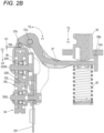
- Fig. 2B and Fig. 2C each is a cross-sectional view showing an example of an operation of the wire feeding unit during wire loading.
- a configuration of the wire feeding unit 3A will be described with reference to each drawing.
- the first feed gear 30L which is one feed member forming one of the pair of feed gears 30, is rotatably supported on the support member 301 of the wire feeding unit 3A by the shaft 300L.
- the first feed gear 30L includes a tooth portion 31L that transmits a driving force.
- the tooth portion 31L has a shape forming a spur gear, and is formed along an entire outer periphery of the first feed gear 30L.
- the first feed gear 30L includes a groove portion 32L into which the wire W is inserted.
- the groove portion 32L includes a concave portion having a substantially V-shaped cross section, and is formed along the entire outer periphery of the first feed gear 30L in a circumferential direction.
- the second feed gear 30R which is the other feed member forimg the other of the pair of feed gears 30, includes a tooth portion 31R that transmits a driving force.
- the tooth portion 31R has a shape forming a spur gear, and is formed along an entire outer periphery of the second feed gear 30R.
- the second feed gear 30R includes a groove portion 32R into which the wire W is inserted.
- the groove portion 32R includes a concave portion having a substantially V-shaped cross section, and is formed along the entire outer periphery of the second feed gear 30R in a circumferential direction.
- the groove portion 32L of the first feed gear 30L and the groove portion 32R of the second feed gear 30R are opposed to each other, and the first feed gear 30L and the second feed gear 30R are provided with the feed path of the wire W interposed therebetween.
- the tooth portion 31L of the first feed gear 30L and the tooth portion 31R of the second feed gear 30R mesh with each other in a state in which the wire W is clamped between the groove portion 32L of the first feed gear 30L and the groove portion 32R of the second feed gear 30R. Accordingly, a driving force is transmitted between the first feed gear 30L and the second feed gear 30R.
- the wire feeding unit 3A includes a feed motor 33 that drives one of the first feed gear 30L and the second feed gear 30R, drives the first feed gear 30L in this example, and a driving force transmission mechanism 34 that transmits a driving force of the feed motor 33 to the first feed gear 30L.
- the driving force transmission mechanism 34 includes a small gear 33a attached to a shaft of the feed motor 33 and a large gear 33b meshing with the small gear 33a.
- the driving force transmission mechanism 34 includes a feed small gear 34a to which a driving force is transmitted from the large gear 33b and which meshes with the first feed gear 30L.
- Each of the small gear 33a, the large gear 33b and the feed small gear 34a includes a spur gear.
- a rotation operation of the feed motor 33 is transmitted to the first feed gear 30L via the driving force transmission mechanism 34 to rotate the first feed gear 30L.
- a rotation operation of the first feed gear 30L is transmitted to the second feed gear 30R by meshing between the tooth portion 31L and the tooth portion 31R, and the second feed gear 30R rotates following the first feed gear 30L.
- the wire feeding unit 3A feeds, along the extending direction of the wire W, the wire W clamped between the first feed gear 30L and the second feed gear 30R.
- the two wires W are fed in parallel by a frictional force generated between the groove portion 32L of the first feed gear 30L and one wire W, a frictional force generated between the groove portion 32R of the second feed gear 30R and the other wire W, and a frictional force generated between the one wire W and the other wire W.
- the wire feeding unit 3A by switching a rotation direction of the feed motor 33 between a forward direction and a backward direction, rotation directions of the first feed gear 30L and the second feed gear 30R are switched, and a feed direction of the wire W is switched between a forward direction and a backward direction.
- the wire feeding unit 3A clamps the wire W between the first feed gear 30L and the second feed gear 30R
- the wire feeding unit 3A includes a configuration in which the first feed gear 30L and the second feed gear 30R are pressed in a direction in which the first feed gear 30L and the second feed gear 30R approach each other. That is, in order to allow the wire feeding unit 3A to load one wire W between the first feed gear 30L and the second feed gear 30R while clamping the other wire W between the first feed gear 30L and the second feed gear 30R, the first feed gear 30L and the second feed gear 30R are configured to be displaceable in a direction in which the first feed gear 30L and the second feed gear 30R separate from and contact with each other.
- the driving force of the feed motor 33 is received by the first feed gear 30L, and the second feed gear 30R to which the driving force of the feed motor 33 is not directly transmitted is displaced with respect to the first feed gear 30L.
- the wire feeding unit 3A includes a first displacement member 36 that displaces the second feed gear 30R with respect to the first feed gear 30L in a direction to approach and separate from the first feed gear 30L.
- the wire feeding unit 3A includes a second displacement member 37 that displaces the first displacement member 36.
- the first displacement member 36 and the second displacement member 37 are examples of a displacement unit, and displace one or both of the pair of feed gears 30 in a direction to approach and separate from each other.
- the second feed gear 30R is displaced with respect to the first feed gear 30L in the direction to approach and separate from the first feed gear 30L.
- the second feed gear 30R is rotatably supported on one end side of the first displacement member 36 by a shaft 300R.
- the shaft 300L of the first feed gear 30L and the shaft 300R of the second feed gear 30R are parallel to each other.
- the other end of the first displacement member 36 is rotatably supported on the support member 301 of the wire feeding unit 3A with the shaft 36a as a fulcrum.
- the shaft 36a which is the fulcrum for the rotation operation, is oriented parallel to the shaft 300R of the second feed gear 30R. Accordingly, the first displacement member 36 is displaced by the rotation operation with the shaft 36a as a fulcrum, and causes the second feed gear 30R to separate from and contact with the first feed gear 30L.
- the first displacement member 36 includes a pressed portion 36b on the one end side which is pressed by the second displacement member 37.
- the pressed portion 36b is provided on a side of a portion supporting the shaft 300R of the second feed gear 30R.
- the second displacement member 37 is rotatably supported on the support member 301 of the wire feeding unit 3A with a shaft 37a as a fulcrum.
- the second displacement member 37 includes a pressing portion 37b, which presses the pressed portion 36b of the first displacement member 36, on one end side with the shaft 37a therebetween.
- the second displacement member 37 is displaced by the rotation operation with the shaft 37a as a fulcrum to press the pressed portion 36b of the first displacement member 36 by the pressing portion 37b, and release the pressing of the pressed portion 36b by the pressing portion 37b.
- the wire feeding unit 3A includes a spring 38 that presses the second feed gear 30R against the first feed gear 30L.
- the spring 38 includes, for example, a compression coil spring, and presses the other end side of the second displacement member 37 with the shaft 37a therebetween.
- the second displacement member 37 is pressed by the spring 38 and displaced by the rotation operation with the shaft 37a as a fulcrum to press the pressed portion 36b of the first displacement member 36 by the pressing portion 37b.
- the pressing portion 37b of the second displacement member 37 presses the pressed portion 36b of the first displacement member 36
- the first displacement member 36 is displaced by the rotation operation with the shaft 36a as a fulcrum.
- the second feed gear 30R is pressed toward the first feed gear 30L by a force of the spring 38.
- the tooth portion 31L of the first feed gear 30L and the tooth portion 31R of the second feed gear 30R mesh with each other in a state in which the wire W is clamped between the groove portion 32L of the first feed gear 30L and the groove portion 32R of the second feed gear 30R.
- the wire feeding unit 3A includes an operation button 39 that displaces the second displacement member 37.
- the operation button 39 is an example of an operation member, and is provided at a position facing the spring 38 via the second displacement member 37.
- the operation button 39 protrudes outward from one side surface of the main body portion 10A and is supported so as to be movable in a direction indicated by an arrow T1 in which the operation button 39 is pressed toward the main body portion 10A and a direction indicated by an arrow T2 in which the operation button 39 protrudes from the main body portion 10A.
- the spring 38 is contracted by pressing the operation button 39 in the direction indicated by the arrow T1 in which the operation button 39 is pressed toward the main body portion 10A, and the second displacement member 37 sandwiched between the operation button 39 and the spring 38 is displaced by the rotation operation with the shaft 37a as a fulcrum and rotated in a direction indicated by an arrow Y1.
- the wire feeding unit 3A includes a holding unit 39a that secures an interval between the first feed gear 30L and the second feed gear 30R in a state in which the wire W is not inserted between the first feed gear 30L and the second feed gear 30R.
- the holding unit 39a is an example of a holding member, and is provided on the operation button 39 in this example.
- the holding unit 39a protrudes from a side of the operation button 39, and abuts, by pressing the operation button 39 in the direction indicated by the arrow T2 by the force of the spring 38 via the second displacement member 37, against an inner surface of the main body portion 10A at a portion where the operation button 39 is movably provided.
- a gap G1 can be formed between the pressing portion 37b of the second displacement member 37 and the pressed portion 36b of the first displacement member 36. Therefore, the second feed gear 30R can move by the gap G1 in a direction away from the first feed gear 30L without receiving the force of the spring 38.
- a state in which a gap G2 can be formed between the first feed gear 30L and the second feed gear 30R is maintained in the state in which the wire W is not inserted between the first feed gear 30L and the second feed gear 30R.
- Fig. 3A is a side view showing an example of a wire guide
- Fig. 3B is a bottom view showing the example of the wire guide
- Fig. 3C is a side cross-sectional view showing an example of a wire feeding unit and the wire guide
- Fig. 3D is an enlarged cross-sectional view of a main part of the reinforcing bar binding machine showing a relationship between the wire guide and the wire feeding unit.
- the wire guide 4A is disposed at an upstream side of the feed gears 30 (the first feed gear 30L and the second feed gear 30R) with respect to the feed direction of the wire W fed in the forward direction.
- the wire guide 4A aligns the two inserted wires W in a row along a direction in which the first feed gear 30L and the second feed gear 30R are arranged, and guides the two wires W between the first feed gear 30L and the second feed gear 30R.
- the wire guide 4A includes a guide hole 40A through which each wire W passes.
- a lead-out side opening 40A1 on a downstream side with respect to the feed direction of the wire W fed in the forward direction includes an oval or elliptical opening whose longitudinal direction is along the direction in which the first feed gear 30L and the second feed gear 30R are arranged.
- the lead-out side opening 40A1 has a length in the longitudinal direction approximately twice a diameter of the wire W, and a length in a lateral direction approximately equal to the diameter of the wire W. Accordingly, a direction in which the two wires W lead out from the lead-out side opening 40A1 through the wire guide 4A are aligned in a row is regulated.
- the guide hole 40A is configured such that a lead-in side opening 40A2 on an upstream side with respect to the feed direction of the wire W fed in the forward direction has an opening area larger than that of the lead-out side opening 40A1 on the downstream side. Accordingly, a part or all of an inner surface between the lead-in side opening 40A2 and the lead-out side opening 40A1 is tapered, and the guide hole 40Ahas a conical shape whose opening area gradually decreases from the lead-in side opening 40A2 toward the lead-out side opening 40A1.
- the wire guide 4A includes a leading unit 41A (41A1, 41A2) for the wire W between the lead-in side opening 40A2 and the lead-out side opening 40A1.
- the leading unit 41A includes a leading unit 41A1 positioned outside in a winding direction of the wire W wound on the reel 20 stored in the magazine 2A with respect to the wire W lead into the wire guide 4A, and a leading unit 41A2 positioned inside in the winding direction of the wire W with respect to the wire W lead into the wire guide 4A.
- the leading unit 41A1 and the leading unit 41A2 include an inner surface of the guide hole 40A between the lead-in side opening 40A2 and the lead-out side opening 40A1, and a portion or an entire portion between the lead-in side opening 40A2 and the lead-out side opening 40A1 is tapered.
- the wire W clamped between the groove portion 32L and groove portion 32R passes through a center along an axial direction of the first feed gear 30L and the second feed gear 30R. Therefore, a path through which the wire W passes is called a reference path L, and the path is obtained by connecting, with a straight line, a center of the lead-out side opening 40A1 in the lateral direction, and the center along the axial direction of the first feed gear 30L and the second feed gear 30R provided with the groove portion 32L and the groove portion 32R at the portion where the first feed gear 30L and the second feed gear 30R face each other.
- the path through which the wire W lead into the wire guide 4A passes changes according to an amount of the wire W wound on the reel 20.
- a path through which the wire W passes between the wire guide 4A and the reel 20 stored in the magazine 2A a path when the amount of the wire W wound on the reel 20 is large is indicated by W1 in Fig. 3D
- a path when the amount of the wire W wound on the reel 20 is small is indicated by W2 in Fig. 3D .
- a path W1 through which the wire W lead into the wire guide 4A passes is a path along the reference path L.
- the user of the reinforcing bar binding machine 1A inserts the wire W from the wire guide 4A between the first feed gear 30L and the second feed gear 30R. Since a new reel 20 has a large amount of wire W wound thereon, the wire W is pulled out from the vicinity of the outer periphery of the reel 20. Accordingly, the wire W inserted into the wire guide 4A from the lead-in side opening 40A2 is lead to the lead-out side opening 40A1 along the leading unit 41A1 in a direction along the axial direction of the first feed gear 30L and the second feed gear 30R.
- the leading unit 41A (41A1, 41A2) on a side closer to the lead-out side opening 40A1 may be parallel to the reference path L, and in this case, in the wire guide 4A, the angle ⁇ of the leading unit 41A (41A1, 41A2) on a side closer to the lead-out side opening 40A1 with respect to the reference path L is 0°.
- the angle ⁇ 1 of the leading unit 41A1 with respect to the reference path L should be as small as possible. Therefore, although it is preferable that the angle ⁇ 1 of the leading unit 41A1 with respect to the reference path L is as small as possible, from the viewpoint of ensuring the length L1 of the lead-in side opening 40A2, the angle ⁇ 1 of the leading unit 41A1 with respect to the reference path L is preferably 0° or more and 17° or less, and more preferably more than 0° and 9° or less.
- a path W2 through which the wire W lead into the wire guide 4A passes is a path inclined inward in the winding direction of the wire W wound on the reel 20 with respect to the reference path L.
- the angle ⁇ 2 of the leading unit 41A2 along the axial direction of the first feed gear 30L and the second feed gear 30R preferably has a lower limit value of 10° or more, and an upper limit value of less than 90°.
- the angle ⁇ 2 of the leading unit 41A2 with respect to the reference path L is preferably 10° or more and 70° or less, and more preferably 10° or more and 50° or less.
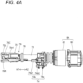
- Fig. 4A is a perspective view showing an example of a binding unit
- Fig. 4B and Fig. 4C each is a cross-sectional plan view showing the example of the binding unit.
- a configuration of the binding unit will be described with reference to each drawing.
- the binding unit 7A includes the wire locking body 70 that locks the wire W and a rotation shaft 72 that actuates the wire locking body 70.
- the rotation shaft 72 and the motor 80 are connected via the reduction gear 81, and the rotation shaft 72 is driven by the motor 80 via the reduction gear 81.
- the wire locking body 70 includes a center hook 70C connected to the rotation shaft 72, a first side hook 70R and a second side hook 70L that are opened and closed with respect to the center hook 70C, and a sleeve 71 that actuates the first side hook 70R and the second side hook 70L and forms the wire W into a desired shape.
- a side on which the center hook 70C, the first side hook 70R, and the second side hook 70L are provided is defined as a front side
- a side on which the rotation shaft 72 is connected to the reduction gear 81 is defined as a rear side.
- the center hook 70C is connected to a front end, which is one end portion of the rotation shaft 72, via a configuration that is rotatable with respect to the rotation shaft 72 and is movable in an axial direction integrally with the rotation shaft 72.
- a tip side of the first side hook 70R which is one end portion along the axial direction of the rotation shaft 72, is located on one side portion of the center hook 70C.
- a rear end side of the first side hook 70R which is the other end portion along the axial direction of the rotation shaft 72, is rotatably supported on the center hook 70C by a shaft 71b.
- a tip side of the second side hook 70L which is one end portion along the axial direction of the rotation shaft 72, is located on the other side portion of the center hook 70C.
- a rear end side of the second side hook 70L which is the other end portion along the axial direction of the rotation shaft 72, is rotatably supported on the center hook 70C by the shaft 71b.
- the wire locking body 70 is opened and closed in a direction in which the tip side of the first side hook 70R is separated from and contacted with the center hook 70C by a rotation operation with the shaft 71b as a fulcrum.
- the wire locking body 70 is opened and closed in a direction in which the tip side of the second side hook 70L is separated from and contacted with the center hook 70C.
- a rear end, which is the other end portion, of the rotation shaft 72 is connected to the reduction gear 81 via a connecting portion 72b that is rotatable integrally with the reduction gear 81 and is movable in the axial direction with respect to the reduction gear 81.
- the connecting portion 72b includes a spring 72c that biases the rotation shaft 72 rearward, which is a direction approaching the reduction gear 81. Accordingly, the rotation shaft 72 is configured to be movable forward, which is a direction away from the reduction gear 81, while receiving a force pulled backward by the spring 72c.
- the sleeve 71 is rotatably and axially slidably supported by a support frame 76.
- the support frame 76 is an annular member, and is attached to the main body portion 10A in a form that cannot rotate in a circumferential direction and cannot move in the axial direction.
- the sleeve 71 includes a convex portion (not shown) that protrudes from an inner peripheral surface of a space into which the rotation shaft 72 is inserted, and the convex portion enters a groove portion of a feed screw 72a formed on an outer periphery of the rotation shaft 72 along the axial direction.
- the sleeve 71 moves in a front-rear direction, which is a direction along the axial direction of the rotation shaft 72, in accordance with a rotation direction of the rotation shaft 72, by an action between the convex portion (not shown) and the feed screw 72a of the rotation shaft 72.
- the sleeve 71 rotates integrally with the rotation shaft 72.
- the sleeve 71 includes an opening and closing pin 71a that opens and closes the first side hook 70R and the second side hook 70L.
- the opening and closing pin 71a is inserted into an opening and closing guide hole 73 provided in the first side hook 70R and the second side hook 70L.
- the opening and closing guide hole 73 extends along a moving direction of the sleeve 71, and has a shape that converts a linear movement of the opening and closing pin 71a moving in conjunction with the sleeve 71 into an opening and closing operation caused by rotation of the first side hook 70R and the second side hook 70L with the shaft 71b as a fulcrum.
- the first side hook 70R and the second side hook 70L move in a direction away from the center hook 70C by the rotation operation with the shaft 71b as a fulcrum according to a trajectory of the opening and closing pin 71a and the shape of the opening and closing guide hole 73.
- first side hook 70R and the second side hook 70L are opened with respect to the center hook 70C, and a feed path through which the wire W passes is formed between the first side hook 70R and the center hook 70C and between the second side hook 70L and the center hook 70C.
- the wire W fed by the wire feeding unit 3A passes between the center hook 70C and the first side hook 70R.
- the wire W passing between the center hook 70C and the first side hook 70R is lead to the curl forming unit 5A.
- the wire W, which is curled by the curl forming unit 5A and lead to the binding unit 7A passes between the center hook 70C and the second side hook 70L.
- the first side hook 70R and the second side hook 70L move in a direction approaching the center hook 70C by the rotation operation with the shaft 71b as a fulcrum according to a trajectory of the opening and closing pin 71a and the shape of the opening and closing guide hole 73. Accordingly, the first side hook 70R and the second side hook 70L are closed with respect to the center hook 70C.
- the wire W sandwiched between the first side hook 70R and the center hook 70C is locked in a form of capable of moving between the first side hook 70R and the center hook 70C.
- the wire W sandwiched between the second side hook 70L and the center hook 70C is locked in a form of not coming off from between the second side hook 70L and the center hook 70C.
- the sleeve 71 includes a bending unit 71c1 that forms the wire W into a predetermined shape by pressing and bending a tip side, which is one end of the wire W, in a predetermined direction, and a bending unit 71c2 that forms the wire W into a predetermined shape by pressing and bending a terminal side, which is the other end of the wire W cut by the cutting unit 6A, in a predetermined direction.
- the sleeve 71 presses, by the bending unit 71c1, the tip side of the wire W, which is locked by the center hook 70C and the second side hook 70L, and bends the tip side toward the reinforcing bars S side.
- the sleeve 71 presses, by the bending unit 71c2, the terminal side of the wire W, which is locked by the center hook 70C and the first side hook 70R and cut by the cutting unit 6A, and bends the terminal side toward the reinforcing bars S side.
- the binding unit 7A includes a rotation regulating unit 74 that regulates rotation of the wire locking body 70 and the sleeve 71 interlocked with a rotation operation of the rotation shaft 72.
- the rotation regulating unit 74 has a rotation regulating blade 74a provided on the sleeve 71 and a rotation regulating pawl 74b provided on the main body portion 10A.
- the rotation regulating blade 74a is formed by providing, at predetermined intervals in a circumferential direction of the sleeve 71, a plurality of convex portions radially protruding from an outer periphery of the sleeve 71.
- the rotation regulating blade 74a is fixed to the sleeve 71 and moves and rotates integrally with sleeve 71.
- the rotation regulating pawl 74b includes a first pawl portion 74b1 and a second pawl portion 74b2 as a pair of pawl portions facing each other with an interval that allows the rotation regulating blade 74a to pass therethrough.
- the first pawl portion 74b1 and the second pawl portion 74b2 are configured to be retractable from a trajectory of the rotation regulating blade 74a by being pushed by the rotation regulating blade 74a according to a rotation direction of the rotation regulating blade 74a.
- the rotation regulating unit 74 when the rotation regulating blade 74a is locked to the rotation regulating pawl 74b, the rotation of the sleeve 71 interlocked with the rotation of the rotation shaft 72 is regulated, and the sleeve 71 moves in the front-rear direction by the rotation operation of the rotation shaft 72. In addition, when the locking of the rotation regulating blade 74a to the rotation regulating pawl 74b is released, the sleeve 71 rotates in conjunction with the rotation of the rotation shaft 72.
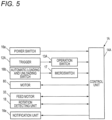
- Fig. 5 is a block diagram showing an example of a control function of the reinforcing bar binding machine.
- the reinforcing bar binding machine 1A performs a series of operations including the control unit 14A controlling the motor 80 and the feed motor 33 to bind the reinforcing bars S with the wire W according to a state of the operation switch 13A pressed by operating the trigger 12A shown in Figs. 1A and 1B .
- the control unit 14A switches power on and off by operating the power switch 16a.
- the control unit 14A controls the feed motor 33 based on an output of a microswitch 17 by operating the automatic loading and unloading switch 16b to load and unload the wire W by the wire feeding unit 3A.
- the automatic loading and unloading switch 16b is a push-button type switch in this example, and is configured to actuate the microswitch 17 when pressed.
- the feed motor 33 is formed of a brushless motor in this example, and includes a rotation detecting unit 18 such as a Hall IC for detecting a rotation position of a rotor.
- the driving force transmission mechanism 34 for transmitting the driving force of the feed motor 33 to the first feed gear 30L includes a spur gear. Accordingly, when the tip of the wire W is inserted between the groove portion 32L of the first feed gear 30L and the groove portion 32R of the second feed gear 30R and the wire W is pushed, in a state in which the feed motor 33 is not rotating due to energization, a behavior (rotation) of the first feed gear 30L and the second feed gear 30R allows the feed motor 33 to be rotated by an external force. That is, the rotation detecting unit 18 is included in a detection unit that detects a movement due to the behavior of the first feed gear 30L and the second feed gear 30R.
- the control unit 14A executes the automatic loading and unloading mode in which an automatic unloading operation and an automatic loading operation of the wire W are executed.
- the control unit 14A may notify, by a notification unit 16e, that the automatic loading and unloading mode is being executed.
- the notification unit 16e may be a buzzer that outputs sound, or a lamp or a display that outputs visible information such as light or display.
- control unit 14A may notify, by the notification unit 16e, that the power is on (the power is ON) and the reinforcing bar binding machine 1A is in a binding standby state.
- the control unit 14A When the automatic loading and unloading mode is executed, the control unit 14A firstly executes the automatic unloading operation to unload the wire W remaining in the reinforcing bar binding machine 1A.
- the feed motor 33 In the automatic unloading operation, the feed motor 33 is rotated in the backward direction, and when the feed motor 33 is rotated in the backward direction by a defined amount of rotation for the unloading operation in which the wire W is came off from between the first feed gear 30L and the second feed gear 30R, the feed motor 33 is stopped.
- the control unit 14A executes the automatic loading operation to load a new wire W into the reinforcing bar binding machine 1A.
- the control unit 14A drives the feed motor 33 in a forward rotation direction to feed the wire W in the forward direction.
- the feed motor 33 When the feed motor 33 is driven in the forward rotation direction by a defined amount of rotation for the loading operation in which the wire W is forwarded by a predetermined amount from a position where the first feed gear 30L and the second feed gear 30R mesh, the feed motor 33 is stopped.
- the control unit 14A ends the automatic loading and unloading mode, and even if the rotation detecting unit 18 detects that the feed motor 33 has rotated in the state in which the feed motor 33 is not rotating due to energization, the control unit 14A does not perform the loading operation described above.
- the control unit 14A ends the automatic loading and unloading mode, and even if the rotation detecting unit 18 detects that the feed motor 33 has rotated in the state in which the feed motor 33 is not rotating due to energization, the control unit 14A does not perform the loading operation described above.
- the control unit 14A changes a state between a first state and a second state to feed the wire W in the forward direction.
- the control unit 14A controls whether the feed motor 33 is driven in the forward rotation direction and a rotation speed between the first state and the second state. Presence or absence of output of the notification information from the notification unit 16e may be combined.
- the first state is a state in which the notification unit 16e gives a predetermined notification.
- the first state is a state in which the feed motor 33 is stopped, or a state in which the feed motor 33 is rotated in the forward direction at a first rotation speed lower than a second rotation speed.
- the first state may be a combination of the state in which the notification unit 16e gives a predetermined notification and the state in which the feed motor 33 is stopped.
- the wire W is clamped between the first feed gear 30L and the second feed gear 30R, and a state in which the tip of the wire W is positioned between the clamping position of the pair of feed gears 30 and the cutting unit 6A is a standby state (standby position).
- the reinforcing bar binding machine 1A is in a state in which the first side hook 70R is opened with respect to the center hook 70C and the second side hook 70L is opened with respect to the center hook 70C.
- the control unit 14A drives the feed motor 33 in the forward rotation direction, which is the first rotation direction, so that the wire feeding unit 3A feeds the wire W in the forward direction indicated by the arrow F, which is the first direction.
- the two wires W are fed by the wire guide 4A in a state of being arranged in parallel along an axial direction of the loop Ru formed by the wires W.
- the wire W fed in the forward direction passes between the center hook 70C and the first side hook 70R and is fed to the curl guide 50 of the curl forming unit 5A.
- the wire W is curled to be wound around the reinforcing bars S by passing through the curl guide 50.
- the wire W curled by the curl guide 50 is lead by the leading guide 51 and further fed in the forward direction by the wire feeding unit 3A, so that the wire W is lead between the center hook 70C and the second side hook 70L by the leading guide 51. Then, the wire W is fed until the tip thereof abuts against the feed regulating unit 90. When the tip of the wire W is fed to a position where the tip abuts against the feed regulating unit 90, the control unit 14A stops driving the feed motor 33.
- the control unit 14A drives the motor 80 in the forward rotation direction.
- the rotation of the sleeve 71 interlocked with the rotation of the rotation shaft 72 is regulated by locking the rotation regulating blade 74a to the rotation regulating pawl 74b. Accordingly, rotation of the motor 80 is converted into a linear movement, and the sleeve 71 moves in the direction indicated by the arrow A1 which is a forward direction.
- the opening and closing pin 71a passes through the opening and closing guide hole 73. Accordingly, the first side hook 70R moves in a direction approaching the center hook 70C by the rotation operation with the shaft 71b as a fulcrum.
- the wire W sandwiched between the first side hook 70R and the center hook 70C is locked in a form of capable of moving between the first side hook 70R and the center hook 70C.
- the second side hook 70L moves in a direction approaching the center hook 70C by the rotation operation with the shaft 71b as a fulcrum.
- the wire W sandwiched between the second side hook 70L and the center hook 70C is locked in a form of not coming off from between the second side hook 70L and the center hook 70C.
- the control unit 14A temporarily stops the rotation of the motor 80 and drives the feed motor 33 in a backward rotation direction, which is the second rotation direction opposite to the first rotation direction. Accordingly, the pair of feed gears 30 are rotated in the backward direction.
- the wire W clamped between the pair of feed gears 30 is fed in the backward direction indicated by the arrow R, which is the second direction. Since the tip side of the wire W is locked in the form of not coming off from between the second side hook 70L and the center hook 70C, the wire W is wound around the reinforcing bars S by the operation of feeding the wire W in the backward direction.
- the wire W is pulled back to a position where the wire W is wound around the reinforcing bars S, and after the driving of the feed motor 33 in the backward rotation direction is stopped, the control unit 14A drives the motor 80 in the forward rotation direction to move the sleeve 71 in the forward direction indicated by the arrow A1.
- the operation of the sleeve 71 moving in the forward direction is transmitted to the cutting unit 6A by the transmission mechanism 62, thereby cutting the wire W locked by the first side hook 70R and the center hook 70C.
- the bending units 71c1 and 71c2 move in a direction approaching the reinforcing bars S at substantially the same time as the wire W is cut. Accordingly, the tip side of the wire W locked by the center hook 70C and the second side hook 70L is pressed toward the reinforcing bars S by the bending unit 71c1, and bent toward the reinforcing bars S with the locking position as a fulcrum. By further moving the sleeve 71 in the forward direction, the wire W locked between the second side hook 70L and the center hook 70C is held in a state of being sandwiched by the bending unit 71c1.
- the terminal side of the wire W locked by the center hook 70C and the first side hook 70R and cut by the cutting unit 6A is pressed toward the reinforcing bars S by the bending unit 71c2, and bent toward the reinforcing bars S with the locking position as a fulcrum.
- the sleeve 71 By further moving the sleeve 71 in the forward direction, the wire W locked between the first side hook 70R and the center hook 70C is held in a state of being sandwiched by the bending unit 71c2.
- the sleeve 71 After the tip side and the terminal side of the wire W are bent toward the reinforcing bars S, the sleeve 71 further moves in the forward direction by further driving the motor 80 in the forward rotation direction. When the sleeve 71 moves to a predetermined position and reaches an operating range where the wire W locked by the wire locking body 70 is twisted, the locking of the rotation regulating blade 74a to the rotation regulating pawl 74b is released.
- the wire locking body 70 rotates in conjunction with the rotation shaft 72, and the wire W is twisted.
- the binding unit 7A twists the wire W to apply a force for pulling the wire locking body 70 forward along the axial direction of the rotation shaft 72.
- the rotation shaft 72 is configured to, when a force for moving the wire locking body 70 forward along the axial direction is applied to the wire locking body 70, be movable forward while receiving a backward pushing force from the spring 72c. Accordingly, the binding unit 7A twists the wire W while the wire locking body 70 and the rotation shaft 72 move forward in the operating range where the sleeve 71 rotates.
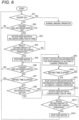
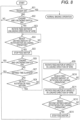
- Figs. 6 , 7 and 8 each is a flowchart showing an example of operations in the automatic loading and unloading mode. Next, operations of automatically unloading and loading the wire W by the reinforcing bar binding machine 1A will be described.
- a combination of a predetermined operation of the trigger 12A and a predetermined operation of the automatic loading and unloading switch 16b is assigned to execute the automatic loading and unloading mode of the wire W.
- the automatic loading and unloading mode is set to start when the automatic loading and unloading switch 16b is operated without operating the trigger 12A.
- the control unit 14A determines whether the trigger 12A is operated at step SA1 in Fig. 6 , and determines whether the automatic loading and unloading switch 16b is operated at step SA2.
- a matter that the trigger 12A is operated is also referred to as trigger ON
- a matter that the automatic loading and unloading switch 16b is operated is also referred to as loading and unloading switch ON.
- control unit 14A When the trigger 12A is operated, the control unit 14A performs the binding operation described above.
- the control unit 14A determines that an operation of executing the automatic loading and unloading mode is performed.
- the control unit 14A determines that the operation of starting the automatic loading and unloading mode is performed, the control unit 14A firstly performs the automatic unloading operation in the automatic loading and unloading mode.
- the feed motor 33 is driven in the backward rotation direction, which is an unloading direction of the wire W
- step SA4 in Fig. 6 when an amount of rotation of the feed motor 33 in the backward rotation direction reaches the defined amount of rotation for the unloading operation in which the wire W is came off from between the first feed gear 30L and the second feed gear 30R, the control unit 14A stops the rotation of the feed motor 33 in the backward rotation direction at step SA5.
- control unit 14A may compare the value of the current flowing through the feed motor 33 with a predetermined set threshold for detecting absence of the wire W between the first feed gear 30L and the second feed gear 30R, and determine whether the wire W is came off from between the first feed gear 30L and the second feed gear 30R.
- an operation of driving the cutting unit 6A to cut the wire W and an operation of returning the binding unit 7A to the standby state may be performed before the wire W is fed in the backward direction in the automatic unloading operation.
- the control unit 14A determines that the operation of starting the automatic loading and unloading mode described above is performed, the control unit 14A drives the motor 80 in the forward rotation direction to move the sleeve 71 in the forward direction indicated by the arrow A1 to perform the wire cutting operation by the cutting unit 6A.
- the wire W When the wire W is in a position where the wire W can be cut by the cutting unit 6A, the wire W is cut, and the wire W on the binding unit 7A side from the cutting unit 6A and the wire W on the wire feeding unit 3A side from the cutting unit 6A are separated.
- the control unit 14A drives the motor 80 in the backward rotation direction to move the sleeve 71 in the rearward direction indicated by the arrow A2 to return the binding unit 7A to the standby state described above.
- the control unit 14A drives the feed motor 33 in the backward rotation direction to perform the automatic unloading operation at step SA3 described above.
- the control unit 14A unloads the wire W from between the first feed gear 30L and the second feed gear 30R in the automatic unloading operation during execution of the automatic loading and unloading mode and stops driving the feed motor 33, and then performs the automatic loading operation by a predetermined operation.
- the automatic loading operation is started.
- the control unit 14A determines whether a predetermined state for ending the automatic loading and unloading mode is reached. That is, the control unit 14A determines at step SA6 whether the automatic loading and unloading switch 16b is operated again during execution of the automatic loading and unloading mode after the automatic unloading operations from steps SA1 to SA5 in Fig. 6 described above are performed, and determines at step SA7 whether a defined time for ending the automatic loading and unloading mode elapses after the automatic unloading operation is performed.
- the control unit 14A determines at step SA6 that the automatic loading and unloading switch 16b is operated again during execution of the automatic loading and unloading mode, the control unit 14A ends the automatic loading and unloading mode and does not perform the following automatic loading operations. That is, when the automatic loading and unloading switch 16b is operated again after the wire W is unloaded from between the first feed gear 30L and the second feed gear 30R and before a next wire W is inserted into a position where the wire W can be fed in the forward direction by the first feed gear 30L and the second feed gear 30R, the automatic loading and unloading mode is ended.
- control unit 14A determines at step SA7 that the defined time for ending the automatic loading and unloading mode elapses with a predetermined operation of starting the automatic loading operation not performed after the automatic unloading operation is performed, the control unit 14A ends the automatic loading and unloading mode and does not perform the following automatic loading operations. That is, after the wire W is unloaded from between the first feed gear 30L and the second feed gear 30R, even if the automatic loading and unloading switch 16b is not operated again, when the defined time elapses before the wire W is inserted into the position where the wire W can be fed in the forward direction by the first feed gear 30L and the second feed gear 30R, the automatic loading and unloading mode is ended.
- the automatic loading and unloading switch 16b After the automatic unloading operation of the wire W is performed, the automatic loading and unloading switch 16b is not operated, and before the defined time for ending the automatic loading and unloading mode elapses, when the wire W is inserted into the position where the wire W can be fed in the forward direction by the first feed gear 30L and the second feed gear 30R in an insertion standby state in which the wire W is separated from the first feed gear 30L and the second feed gear 30R, the control unit 14A performs the automatic loading operation in the automatic loading and unloading mode.
- the control unit 14A detects that the wire W is inserted into the position where the wire W can be fed in the forward direction by the first feed gear 30L and the second feed gear 30R, the control unit 14A determines, at step SA8 in Fig. 6 and by the rotation detecting unit 18, whether the feed motor 33 is rotated in the forward rotation direction without driving the control unit 14A.
- control unit 14A may determine, by detecting a position of the wire W by a sensor (not shown), that the wire W is inserted into the position where the wire W can be fed in the forward direction by the first feed gear 30L and the second feed gear 30R.
- the automatic loading and unloading switch 16b After the automatic unloading operation of the wire W is performed, the automatic loading and unloading switch 16b is not operated, and before the defined time for ending the automatic loading and unloading mode elapses, when the control unit 14A determines, by the rotation detecting unit 18, that the feed motor 33 is rotated in the forward rotation direction without driving the control unit 14A, the control unit 14A drives, at step SA9 in Fig. 6 , the notification unit 16e to sound a buzzer to start outputting notification information for performance of the automatic loading operation, which is notification information to notify performance of the automatic loading operation, as the first state.
- the control unit 14A determines at step SA10 in Fig. 6 that the notification information for performance of the automatic loading operation is output for a predetermined time
- the control unit 14A stops outputting the notification information for performance of the automatic loading operation at step SA11.
- the control unit 14A does not drive the feed motor 33 and makes the feed motor 33 not rotate while outputting the notification information for performance of the automatic loading operation as the first state. Accordingly, the wire W is not fed in the forward direction while the notification information for performance of the automatic loading operation is being output, which is the wire feed standby time.
- the control unit 14A drives, at step SA12 in Fig. 6 , the feed motor 33 in the forward rotation direction, which is a loading direction of the wire W, as the second state.
- the feed motor 33 is driven in the forward rotation direction, the wire W is fed in the forward direction, which is the loading direction.
- the control unit 14A determines whether an amount of rotation of the feed motor 33 reaches a defined amount of rotation at which the wire W is forwarded by a predetermined amount from the position where the first feed gear 30L and the second feed gear 30R mesh.
- the control unit 14A determines at step SA13 in Fig. 6 that an amount of rotation of the feed motor 33 in the forward direction reaches the defined amount of rotation for the loading operation, the control unit 14A stops the rotation of the feed motor 33 in the forward rotation direction at step SA14_
- a so-called initializing operation may be performed to position the tip of the wire W at a predetermined position.
- the control unit 14A determines that a feed amount of the wire W reaches a predetermined amount and the tip of the wire W is fed to the position where the wire W can be cut by the cutting unit 6A, the control unit 14A stops driving the feed motor 33.
- control unit 14A drives the motor 80 in the forward rotation direction to move the sleeve 71 in the forward direction as indicated by the arrow A1 to cut the wire W by the cutting unit 6A. Then, the control unit 14A drives the motor 80 in the backward rotation direction to move the sleeve 71 in the rearward direction indicated by the arrow A2 to make the binding unit 7A be in the standby state described above. Accordingly, the wire W is clamped between the first feed gear 30L and the second feed gear 30R, and the tip of the wire W is in a standby position positioned between the clamping position of the pair of feed gears 30 and the cutting unit 6A.
- the automatic loading operation may be an independent operation rather than a continuous operation from the automatic unloading operation.
- the trigger 12A is not operated and the automatic loading and unloading switch 16b is operated, it is determined that an operation of performing the automatic loading operation is performed, and the automatic loading operation is performed by the processes from step SA8 described above.
- the output of the notification information for performance of the automatic loading operation is started as the first state.
- the feed motor 33 is not driven and is not rotated while the notification information for performance of the automatic loading operation is being output. Then, when the output of the notification information for performance of the automatic loading operation is ended, the feed motor 33 is driven in the forward rotation direction, which is the loading direction of the wire W, as the second state.
- Automatic unloading operations from step SB1 to step SB5 in Fig. 7 are the same as the automatic unloading operations from step SA1 to step SA5 in Fig. 6 described above. That is, at steps SB1 and SB2, when the automatic loading and unloading switch 16b is operated with the trigger 12Anot operated in a state in which the automatic loading and unloading mode is not executed, it is determined that an operation of executing the automatic loading and unloading mode is performed.
- the control unit 14A determines that the operation of executing the automatic loading and unloading mode is performed, the control unit 14A firstly performs the automatic unloading operation in the automatic loading and unloading mode.
- the automatic unloading operation at steps SB3, SB4 and SB5 in Fig. 7 , when the feed motor 33 is driven in the backward rotation direction, which is the unloading direction of the wire W, and the amount of rotation of the feed motor 33 in the backward rotation direction reaches the defined amount of rotation for the unloading operation, the rotation of the feed motor 33 in the backward rotation direction is stopped.
- the control unit 14A determines at step SB6 whether the automatic loading and unloading switch 16b is operated again after the automatic unloading operations from steps SB1 to SB5 in Fig. 7 described above are performed, and determines at step SB7 whether a defined time elapses after the automatic unloading operation is performed.
- control unit 14A determines at step SB6 that the automatic loading and unloading switch 16b is operated again, the control unit 14A ends the automatic loading and unloading mode and does not perform the following automatic loading operations. In addition, when the control unit 14A determines at step SB7 that the defined time elapses, the control unit 14A ends the automatic loading and unloading mode and does not perform the following automatic loading operations.
- the automatic loading and unloading switch 16b After the automatic unloading operation of the wire W is performed, the automatic loading and unloading switch 16b is not operated, and before the defined time for ending the automatic loading and unloading mode elapses, when the wire W is inserted into the position where the wire W can be fed in the forward direction by the first feed gear 30L and the second feed gear 30R, the control unit 14A performs the automatic loading operation in the automatic loading and unloading mode.
- the control unit 14A determines at step SB8 in Fig. 7 that the feed motor 33 is rotated in the forward rotation direction without driving the control unit 14A
- the control unit 14A drives, at step SB9, the feed motor 33 at a first rotation speed V1 in the forward rotation direction, which is the loading direction of the wire W, as the first state.
- the first rotation speed V1 is lower than a second rotation speed V2, which is a rotation speed for feeding the wire W in the forward direction in the binding operation described above or a rotation speed for feeding the tip of the wire W to the standby position.
- the control unit 14A determines whether an amount of rotation of the feed motor 33 reaches a first defined amount of rotation at which the wire W is forwarded by a first predetermined amount from the position where the first feed gear 30L and the second feed gear 30R mesh.
- the control unit 14A determines at step SB10 in Fig. 7 that an amount of rotation of the feed motor 33 in the forward direction reaches the first defined amount of rotation for the loading operation, the control unit 14A stops the rotation of the feed motor 33 in the forward rotation direction at step SB11.
- the control unit 14A stops the rotation of the feed motor 33 at the first rotation speed V1
- the control unit 14A starts outputting the notification information for performance of the automatic loading operation at step SB12 in Fig. 7 , as the first state.
- the control unit 14A determines at step SB13 in Fig. 7 that the notification information for performance of the automatic loading operation is output for a predetermined time
- the control unit 14A stops outputting the notification information for performance of the automatic loading operation at step SB14.
- the control unit 14A does not drive the feed motor 33 and makes the feed motor 33 not rotate while outputting the notification information for performance of the automatic loading operation. Accordingly, the wire W is not fed in the forward direction while the notification information for performance of the automatic loading operation is being output.
- the control unit 14A drives, at step SB15 in Fig. 7 , the feed motor 33 at the second rotation speed V2 in the forward rotation direction, which is a loading direction of the wire W, as the second state.
- the feed motor 33 is driven in the forward rotation direction, the wire W is fed in the forward direction, which is the loading direction.
- the control unit 14A determines whether the amount of rotation of the feed motor 33 reaches a second defined amount of rotation at which the wire W forwarded by the first predetermined amount from the position where the first feed gear 30L and the second feed gear 30R mesh is further fed by a second predetermined amount.
- the control unit 14A determines at step SB16 in Fig. 7 that the amount of rotation of the feed motor 33 in the forward direction reaches the second defined amount of rotation for the loading operation, the control unit 14A stops the rotation of the feed motor 33 in the forward rotation direction at step SB17.
- step SB15 in Fig. 7 the feed motor 33 is driven at the second rotation speed V2 in the forward rotation direction, which is the loading direction of the wire W, and when it is determined that the amount of rotation of the feed motor 33 in the forward direction at the second rotation speed V2 reaches the second defined amount of rotation for the loading operation, the rotation of the feed motor 33 in the forward rotation direction may be stopped.
- a so-called initializing operation may be performed to position the tip of the wire W at a predetermined position.
- the automatic loading operation maybe an independent operation rather than a continuous operation from the automatic unloading operation.
- the trigger 12A is not operated and the automatic loading and unloading switch 16b is operated, it is determined that an operation of performing the automatic loading operation is performed, and the automatic loading operation is performed by the processes from step SB8 described above.
- the feed motor 33 is driven at the first rotation speed V1 in the forward rotation direction, which is the loading direction of the wire W, as the first state.
- the first rotation speed V1 is lower than the second rotation speed V2, which is a rotation speed for feeding the wire W in the forward direction in the binding operation described above or a rotation speed for feeding the tip of the wire W to the standby position.
- the rotation of the feed motor 33 in the forward rotation direction is stopped, and the output of the notification information for performance of the automatic loading operation is started.
- the feed motor 33 is not driven and is not rotated while the notification information for performance of the automatic loading operation is being output.
- the feed motor 33 is driven at the second rotation speed V2 or the first rotation speed V1 in the forward rotation direction, which is the loading direction of the wire W, as the second state.
- the wire W is fed in the forward direction by driving the feed motor 33 can be recognized based on the notification information for performance of the automatic loading operation and a fact of feeding the wire W in the forward direction by rotating the feed motor 33 in the forward direction at the first rotation speed V1.
- Automatic unloading operations from step SC1 to step SC5 in Fig. 8 are the same as the automatic unloading operations from step SA1 to step SA5 in Fig. 6 described above. That is, at steps SC1 and SC2, when the automatic loading and unloading switch 16b is operated with the trigger 12Anot operated in a state in which the automatic loading and unloading mode is not executed, it is determined that an operation of executing the automatic loading and unloading mode is performed.
- the control unit 14A determines that the operation of executing the automatic loading and unloading mode is performed, the control unit 14A firstly performs the automatic unloading operation in the automatic loading and unloading mode.
- the automatic unloading operation at steps SC3, SC4 and SC5 in Fig. 8 , when the feed motor 33 is driven in the backward rotation direction, which is the unloading direction of the wire W, and the amount of rotation of the feed motor 33 in the backward rotation direction reaches the defined amount of rotation for the unloading operation, the rotation of the feed motor 33 in the backward rotation direction is stopped.
- the control unit 14A determines at step SC6 whether the automatic loading and unloading switch 16b is operated again after the automatic unloading operations from steps SC1 to SC5 in Fig. 8 described above are performed, and determines at step SC7 whether a defined time elapses after the automatic unloading operation is performed.
- control unit 14A determines at step SC6 that the automatic loading and unloading switch 16b is operated again, the control unit 14A ends the automatic loading and unloading mode and does not perform the following automatic loading operations. In addition, when the control unit 14A determines at step SC7 that the defined time elapses, the control unit 14A ends the automatic loading and unloading mode and does not perform the following automatic loading operations.
- the automatic loading and unloading switch 16b After the automatic unloading operation of the wire W is performed, the automatic loading and unloading switch 16b is not operated, and before the defined time for ending the automatic loading and unloading mode elapses, when the wire W is inserted into the position where the wire W can be fed in the forward direction by the first feed gear 30L and the second feed gear 30R, the control unit 14A performs the automatic loading operation in the automatic loading and unloading mode.
- the control unit 14A determines at step SC8 in Fig. 8 that the feed motor 33 is rotated in the forward rotation direction without driving the control unit 14A
- the control unit 14A drives, at step SC9, the feed motor 33 at the first rotation speed V1 in the forward rotation direction, which is the loading direction of the wire W, as the first state.
- the feed motor 33 is driven in the forward rotation direction, the wire W is fed in the forward direction, which is the loading direction.
- the first rotation speed V1 is lower than the second rotation speed V2, which is a rotation speed for feeding the wire W in the forward direction in the binding operation described above or a rotation speed for feeding the tip of the wire W to the standby position.
- the control unit 14A determines whether an amount of rotation of the feed motor 33 reaches a first defined amount of rotation at which the wire W is forwarded by a first predetermined amount from the position where the first feed gear 30L and the second feed gear 30R mesh.
- the control unit 14A determines at step SC10 in Fig. 8 that the amount of rotation of the feed motor 33 in the forward direction reaches the first defined amount of rotation for the loading operation
- the control unit 14A drives, at step SC11 in Fig. 8 , the feed motor 33 at the second rotation speed V2 in the forward rotation direction, which is the loading direction of the wire W, as the second state.
- the control unit 14A determines whether the amount of rotation of the feed motor 33 reaches a second defined amount of rotation at which the wire W forwarded by the first predetermined amount from the position where the first feed gear 30L and the second feed gear 30R mesh is further fed by a second predetermined amount.
- the control unit 14A determines at step SC12 in Fig. 8 that the amount of rotation of the feed motor 33 in the forward direction reaches the second defined amount of rotation for the loading operation, the control unit 14A stops the rotation of the feed motor 33 in the forward rotation direction at step SC13.
- a so-called initializing operation may be performed to position the tip of the wire W at a predetermined position.
- the automatic loading operation may be an independent operation rather than a continuous operation from the automatic unloading operation.
- the trigger 12A is not operated and the automatic loading and unloading switch 16b is operated, it is determined that an operation of performing the automatic loading operation is performed, and the automatic loading operation is performed by the processes from step SC8 described above.
- the feed motor 33 is driven at the first rotation speed V1 in the forward rotation direction, which is the loading direction of the wire W, as the first state.
- the first rotation speed V1 is lower than the second rotation speed V2, which is a rotation speed for feeding the wire W in the forward direction in the binding operation described above or a rotation speed for feeding the tip of the wire W to the standby position.
- the feed motor 33 is driven at the second rotation speed V2 in the forward rotation direction, which is the loading direction of the wire W, as the second state.
- the wire W is fed in the forward direction by driving the feed motor 33 can be recognized based on a fact of feeding the wire W in the forward direction by rotating the feed motor 33 in the forward direction at the first rotation speed V1.
- the second feed gear 30R is pushed by the wire W, and a force for moving the second feed gear 30R away from the first feed gear 30L is generated.
- the second feed gear 30R can move by the gap G1 in a direction away from the first feed gear 30L without receiving the force of the spring 38.
- the second feed gear 30R moves in a direction away from the first feed gear 30L, thereby forming the gap G2 between the first feed gear 30L and the second feed gear 30R, as shown in Fig. 2C . Therefore, since the interval between the groove portion 32L of the first feed gear 30L and the groove portion 32R of the second feed gear 30R facing each other is widened, it is easy to insert the wire W between the first feed gear 30L and the second feed gear 30R.
- step SA8 in Fig. 6 the rotation of the feed motor 33 in the forward rotation direction is detected, and the automatic loading operation of the wire W is started.
- the feed motor 33 is rotated by inserting the wire W between the first feed gear 30L and the second feed gear 30R and rotating the first feed gear 30L.
- the gap G2 can be formed between the first feed gear 30L and the second feed gear 30R by forming the gap G1 between the pressing portion 37b of the second displacement member 37 and the pressed portion 36b of the first displacement member 36, it is necessary to move the second feed gear 30R away from the first feed gear 30L while compressing the spring 38 with a force for pushing the wire W in an extending direction. Accordingly, a high load is applied to the wire W, and problems in loading the wire W, such as the wire W buckling, may occur.
- the second feed gear 30R can move in the direction away from the first feed gear 30L in a state in which the force of the spring 38 is not applied.
- the first feed gear 30L rotates while the second feed gear 30R moves in the direction away from the first feed gear 30L. Therefore, the first feed gear 30L can be rotated while a high load is prevented from being applied to the wire W, and the load due to a pressure of the spring 38 in a case of loading the wire W is reduced, thereby facilitating the loading of the wire W for initiating the automatic loading operation of the automatic loading and unloading mode described above.
- the second feed gear 30R When the wire W is fed between the first feed gear 30L and the second feed gear 30R by the driving force of the feed motor 33, depending on a thickness of the wire W, the second feed gear 30R further moves in the direction indicated by the arrow U1 away from the first feed gear 30L. Therefore, the pressing portion 37b of the second displacement member 37 is pressed by the pressed portion 36b of the first displacement member 36, and the second displacement member 37 rotates in the direction indicated by the arrow Y1 with the shaft 37a as the fulcrum. In this way, the second displacement member 37 is separated from the operation button 39.
- the extending direction of the wire W passing through the wire guide 4A approaches parallel to the reference path L. Accordingly, in the automatic loading and unloading mode described above, by the operation of inserting the wire W between the first feed gear 30L and the second feed gear 30R by the user of the reinforcing bar binding machine 1A, the success rate of the tip of the wire W passing through the wire guide 4A entering between the groove portion 32L of the first feed gear 30L and the groove portion 32R of the second feed gear 30R increases.
- the success rate of the tip of the wire W entering between the groove portion 32L of the first feed gear 30L and the groove portion 32R of the second feed gear 30R increases while difficulty of inserting the wire W into the guide hole 40A from the lead-in side opening 40A2 is prevented from increasing.
Landscapes
- Engineering & Computer Science (AREA)
- Mechanical Engineering (AREA)
- Architecture (AREA)
- Civil Engineering (AREA)
- Structural Engineering (AREA)
- Basic Packing Technique (AREA)
Abstract
Description
- The present disclosure relates to a binding machine that binds objects to be bound such as reinforcing bars with a wire.
- Reinforcing bars are used in concrete structures to improve the strength, and are bound with wires such that the reinforcing bars do not deviate from a predetermined position when concrete is poured.
- A technique is proposed in the related art, in which a binding machine called a reinforcing bar binding machine winds a wire around two or more reinforcing bars, twists the wire wound around the reinforcing bars, and binds the two or more reinforcing bars with the wire. The binding machine includes a binding wire feeding mechanism that feeds a wire wound on a reel and winds the wire around reinforcing bars, a gripping mechanism that grips the wire wound around the reinforcing bars, and a binding wire twisting mechanism that twists the wire by rotationally driving the gripping mechanism, and a trigger operation causes the binding wire feeding mechanism, the gripping mechanism and the binding wire twisting mechanism to operate in sequence to perform one cycle of binding operation.
- When reinforcing bars are bound with a wire, if the binding is loose, the reinforcing bars are deviated from one another, and therefore, it is required to firmly hold the reinforcing bars together.
- Therefore, there is a proposed technique of feeding a wire wound around reinforcing bars in a backward direction and winding the wire around the reinforcing bars (see, for example,
Japanese Patent Application Laid-Open Publication No. 2003-34305 Japanese Utility Patent Application Laid Open Publication No. H07-34110 - In a binding machine that clamps and feeds a wire by a pair of rollers, a technique of detecting that a wire has been inserted and automatically loading the wire is conceivable.
- However, in a technique in which an operation of feeding the wire by driving a motor is started by an operation of inserting the wire between the pair of rollers by a user of the binding machine, it is difficult for the user to recognize at what timing the binding machine detects that the wire is inserted and starts the operation of feeding the wire.
- The present invention is made to solve such a problem, and an object thereof is to provide a binding machine that allows a user of the binding machine to recognize that an operation of feeding the wire by driving a motor is started by an operation of inserting the wire between a pair of feed gears by the user of the binding machine.
- An aspect of the present disclosure relates to a biding machine including a wire feeder configured to feed a wire in a first direction; a curl forming unit forming a wire feeding path for winding, around objects to be bound, a wire fed in the first direction by the wire feeder; a binding unit configured to twist a wire wound around the objects to be bound; and a controller configured to control the wire feeder and the binding unit. The wire feeder includes a pair of feed members configured to clamp a wire and feed a wire by a rotation operation, and a feed motor configured to rotate in a first rotation direction to drive the feed members to feed a wire in the first direction, and the controller changes a state into a first state and a second state to feed a wire in the first direction, when a wire is inserted into a position where a wire is feedable in the first direction by the pair of feed members.
- In the present invention, it is recognized that when the operation of feeding the wire in the first direction is performed, the wire is fed in the first direction by driving the feed motor by changing the state into the first state and the second state.
- According to the present invention, the user of the binding machine can recognize that by the operation of inserting the wire between the pair of feed gears by the user of the binding machine, the wire is fed in the first direction by driving the feed motor.
-
-
Fig. 1A is a side view showing an example of a reinforcing bar binding machine; -
Fig. 1B is a side view showing an example of an internal configuration of the reinforcing bar binding machine; -
Fig. 1C is a perspective view showing the example of the reinforcing bar binding machine; -
Fig. 2A is a perspective view showing an example of a wire feeding unit; -
Fig. 2B is a cross-sectional view showing an example of an operation of the wire feeding unit during wire loading; -
Fig. 2C is a cross-sectional view showing an example of an operation of the wire feeding unit during wire loading; -
Fig. 3A is a side view showing an example of a wire guide; -
Fig. 3B is a bottom view showing the example of the wire guide; -
Fig. 3C is a side cross-sectional view showing an example of a wire feeding unit and the wire guide; -
Fig. 3D is an enlarged cross-sectional view of a main part of the reinforcing bar binding machine showing a relationship between the wire guide and the wire feeding unit; -
Fig. 4A is a perspective view showing an example of a binding unit; -
Fig. 4B is a cross-sectional plan view showing the example of the binding unit; -
Fig. 4C is a cross-sectional plan view showing the example of the binding unit; -
Fig. 5 is a block diagram showing an example of a control function of the reinforcing bar binding machine; -
Fig. 6 is a flowchart showing an example of operations in an automatic loading and unloading mode; -
Fig. 7 is a flowchart showing an example of operations in an automatic loading and unloading mode; and -
Fig. 8 is a flowchart showing an example of operations in an automatic loading and unloading mode. - An example of a reinforcing bar binding machine as an embodiment of a binding machine according to the present invention will be described below with reference to the drawings.
-
Fig. 1A is a side view showing an example of the reinforcing bar binding machine,Fig. 1B is a side view showing an example of an internal configuration of the reinforcing bar binding machine, andFig. 1C is a perspective view showing the example of the reinforcing bar binding machine. A reinforcingbar binding machine 1A is in a form of being held in a hand of an operator for use, and includes amain body portion 10A and ahandle portion 11A. - In addition, the reinforcing
bar binding machine 1A feeds a wire W in a forward direction, which is a first direction indicated by an arrow F, winds the wire W around reinforcing bars S, which are objects to be bound, feeds the wire W wound around the reinforcing bars S in a backward direction, which is a second direction indicated by an arrow R, winds the wire W around the reinforcing bars S, twists the wire W, and binds the reinforcing bars S with the wire W. - In order to implement the functions described above, the reinforcing
bar binding machine 1A includes amagazine 2A in which the wire W is stored, awire feeding unit 3A that feeds the wire W, and awire guide 4A that guides the wire W fed to thewire feeding unit 3A. In addition, the reinforcingbar binding machine 1A includes acurl forming unit 5A that forms a path for winding, around the reinforcing bars S, the wire W fed by thewire feeding unit 3A, and acutting unit 6A that cuts the wire W wound around the reinforcing bars S. Further, the reinforcingbar binding machine 1A includes abinding unit 7A that twists the wire W wound around the reinforcing bars S, and adriving unit 8A that drives thebinding unit 7A. - The magazine 2Arotatably and detachably stores a
reel 20 on which the elongated wire W is wound such that the wire W can be unwound. As the wire W, a wire formed of a plastically deformable metal wire, a wire obtained by coating a metal wire with a resin, or a twisted wire is used. Thereel 20 has a bobbin portion (not shown) around which one or more wires W are wound, and a wire W or a plurality of wires W can be pulled out from thereel 20. - The
wire feeding unit 3A includes a pair of feed gears 30 (first feed gear 30L,second feed gear 30R) that feed the wire W by a rotation operation, as a pair of feed members that clamp and feed a wire W or a plurality of wires W arranged in parallel. Thewire feeding unit 3A rotates the pair offeed gears 30 by transmission of a rotation operation of a feed motor, which will be described later. Accordingly, thewire feeding unit 3A feeds, along an extending direction of the wire W, the wire W clamped between the pair of feed gears 30. In a configuration in which a plurality of, for example, two wires W are fed, the wires W are fed in a state in which the two wires W are arranged in parallel. - The
curl forming unit 5A includes acurl guide 50, which is an example of a first guide unit that imparts curl to the wire W fed by thewire feeding unit 3A, and a leadingguide 51, which is an example of a second guide unit that leads, to thebinding unit 7A, the wire W curled by thecurl guide 50. In the reinforcingbar binding machine 1A, a path of the wire W fed by thewire feeding unit 3A is regulated by thecurl forming unit 5A, so that a trajectory of the wire W is a loop Ru as indicated by a chain double-dashed line inFig. 1B , and the wire W is wound around the reinforcing bars S. - The
cutting unit 6A includes a fixed blade portion (not shown), a movable blade portion (not shown) that cuts the wire W in cooperation with the fixed blade portion, and atransmission mechanism 62 that transmits an operation of thebinding unit 7A to the movable blade portion. Thetransmission mechanism 62 transmits the operation of thebinding unit 7A to thecutting unit 6A via a movingmember 83, and cuts the wire W in conjunction with the operation of thebinding unit 7A. - The
binding unit 7A includes awire locking body 70 that locks the wire W A detailed embodiment of thebinding unit 7A will be described later. Thedriving unit 8A includes amotor 80 and areduction gear 81 that reduces a speed and amplifies a torque. - The reinforcing
bar binding machine 1A includes afeed regulating unit 90 with which a tip of the wire W abuts against a feed path of the wire W locked by thewire locking body 70. In addition, in the reinforcingbar binding machine 1A, thecurl guide 50 and the leadingguide 51 of thecurl forming unit 5A described above are provided on a front end of themain body portion 10A. Further, in the reinforcingbar binding machine 1A, an abuttingportion 91 against which the reinforcing bars S are abutted is provided between thecurl guide 50 and the leadingguide 51 at the front end of themain body portion 10A. - In addition, in the reinforcing
bar binding machine 1A, thehandle portion 11A extends downward from themain body portion 10A. Further, abattery 15A is detachably attached to a lower portion of thehandle portion 11A. In addition, in the reinforcingbar binding machine 1A, themagazine 2A is provided in front of thehandle portion 11A. In the reinforcingbar binding machine 1A, thewire feeding unit 3A, thecutting unit 6A, the bindingunit 7A, thedriving unit 8A that drives thebinding unit 7A, and the like described above are stored in themain body portion 10A. - In the reinforcing
bar binding machine 1A, atrigger 12A is provided on a front side of thehandle portion 11A, and anoperation switch 13A is provided inside thehandle portion 11A. In addition, asubstrate 100 on which a circuit forming acontrol unit 14A, which will be described later, and the like are mounted is provided on themain body portion 10A. - The reinforcing
bar binding machine 1A includes anoperation unit 16 that receives operations of turning on and off a power, setting a binding strength of the wire W, automatically loading the wire W, automatically unloading the wire W, and the like. Theoperation unit 16 is provided on a rear surface of themain body portion 10A, and includes apower switch 16a that turns on and off the power, and an automatic loading and unloadingswitch 16b that receives an operation of executing an automatic loading and unloading mode. In addition, theoperation unit 16 includes atorque dial 16c capable of selecting the binding strength of the wire W, as an example of a binding force setting unit capable of setting the binding strength of the wire W. - The
operation unit 16 includes aconvex portion 16d that protrudes rearward from themain body portion 10A around thepower switch 16a, the automatic loading and unloadingswitch 16b, and thetorque dial 16c, so that positions where thepower switch 16a, the automatic loading and unloadingswitch 16b, and thetorque dial 16c are provided are concaved. Accordingly, thepower switch 16a, the automatic loading and unloadingswitch 16b, and thetorque dial 16c do not protrude rearward from themain body portion 10A, thereby preventing a malfunction. In addition, since the wire W is unloaded and loaded after the power is turned off and on, an operability is improved by providing the automatic loading and unloadingswitch 16b near thepower switch 16a, and by providing the automatic loading and unloadingswitch 16b and thepower switch 16a on thesame operation unit 16 in this example. -
Fig. 2A is a perspective view showing an example of a wire feeding unit,Fig. 2B andFig. 2C each is a cross-sectional view showing an example of an operation of the wire feeding unit during wire loading. Next, a configuration of thewire feeding unit 3A will be described with reference to each drawing. - The
first feed gear 30L, which is one feed member forming one of the pair of feed gears 30, is rotatably supported on thesupport member 301 of thewire feeding unit 3A by theshaft 300L. Thefirst feed gear 30L includes atooth portion 31L that transmits a driving force. In this example, thetooth portion 31L has a shape forming a spur gear, and is formed along an entire outer periphery of thefirst feed gear 30L. In addition, thefirst feed gear 30L includes agroove portion 32L into which the wire W is inserted. In this example, thegroove portion 32L includes a concave portion having a substantially V-shaped cross section, and is formed along the entire outer periphery of thefirst feed gear 30L in a circumferential direction. - The
second feed gear 30R, which is the other feed member forimg the other of the pair of feed gears 30, includes atooth portion 31R that transmits a driving force. In this example, thetooth portion 31R has a shape forming a spur gear, and is formed along an entire outer periphery of thesecond feed gear 30R. In addition, thesecond feed gear 30R includes agroove portion 32R into which the wire W is inserted. In this example, thegroove portion 32R includes a concave portion having a substantially V-shaped cross section, and is formed along the entire outer periphery of thesecond feed gear 30R in a circumferential direction. - In the
wire feeding unit 3A, thegroove portion 32L of thefirst feed gear 30L and thegroove portion 32R of thesecond feed gear 30R are opposed to each other, and thefirst feed gear 30L and thesecond feed gear 30R are provided with the feed path of the wire W interposed therebetween. - In the
wire feeding unit 3A, thetooth portion 31L of thefirst feed gear 30L and thetooth portion 31R of thesecond feed gear 30R mesh with each other in a state in which the wire W is clamped between thegroove portion 32L of thefirst feed gear 30L and thegroove portion 32R of thesecond feed gear 30R. Accordingly, a driving force is transmitted between thefirst feed gear 30L and thesecond feed gear 30R. - The
wire feeding unit 3A includes afeed motor 33 that drives one of thefirst feed gear 30L and thesecond feed gear 30R, drives thefirst feed gear 30L in this example, and a drivingforce transmission mechanism 34 that transmits a driving force of thefeed motor 33 to thefirst feed gear 30L. - The driving
force transmission mechanism 34 includes asmall gear 33a attached to a shaft of thefeed motor 33 and alarge gear 33b meshing with thesmall gear 33a. In addition, the drivingforce transmission mechanism 34 includes a feedsmall gear 34a to which a driving force is transmitted from thelarge gear 33b and which meshes with thefirst feed gear 30L. Each of thesmall gear 33a, thelarge gear 33b and the feedsmall gear 34a includes a spur gear. - A rotation operation of the
feed motor 33 is transmitted to thefirst feed gear 30L via the drivingforce transmission mechanism 34 to rotate thefirst feed gear 30L. A rotation operation of thefirst feed gear 30L is transmitted to thesecond feed gear 30R by meshing between thetooth portion 31L and thetooth portion 31R, and thesecond feed gear 30R rotates following thefirst feed gear 30L. - Accordingly, the
wire feeding unit 3A feeds, along the extending direction of the wire W, the wire W clamped between thefirst feed gear 30L and thesecond feed gear 30R. In a configuration of feeding two wires W, the two wires W are fed in parallel by a frictional force generated between thegroove portion 32L of thefirst feed gear 30L and one wire W, a frictional force generated between thegroove portion 32R of thesecond feed gear 30R and the other wire W, and a frictional force generated between the one wire W and the other wire W. - In the
wire feeding unit 3A, by switching a rotation direction of thefeed motor 33 between a forward direction and a backward direction, rotation directions of thefirst feed gear 30L and thesecond feed gear 30R are switched, and a feed direction of the wire W is switched between a forward direction and a backward direction. - Since the
wire feeding unit 3A clamps the wire W between thefirst feed gear 30L and thesecond feed gear 30R, thewire feeding unit 3A includes a configuration in which thefirst feed gear 30L and thesecond feed gear 30R are pressed in a direction in which thefirst feed gear 30L and thesecond feed gear 30R approach each other. That is, in order to allow thewire feeding unit 3A to load one wire W between thefirst feed gear 30L and thesecond feed gear 30R while clamping the other wire W between thefirst feed gear 30L and thesecond feed gear 30R, thefirst feed gear 30L and thesecond feed gear 30R are configured to be displaceable in a direction in which thefirst feed gear 30L and thesecond feed gear 30R separate from and contact with each other. In this example, the driving force of thefeed motor 33 is received by thefirst feed gear 30L, and thesecond feed gear 30R to which the driving force of thefeed motor 33 is not directly transmitted is displaced with respect to thefirst feed gear 30L. - Therefore, the
wire feeding unit 3A includes afirst displacement member 36 that displaces thesecond feed gear 30R with respect to thefirst feed gear 30L in a direction to approach and separate from thefirst feed gear 30L. In addition, thewire feeding unit 3A includes asecond displacement member 37 that displaces thefirst displacement member 36. Thefirst displacement member 36 and thesecond displacement member 37 are examples of a displacement unit, and displace one or both of the pair of feed gears 30 in a direction to approach and separate from each other. In this example, as described above, thesecond feed gear 30R is displaced with respect to thefirst feed gear 30L in the direction to approach and separate from thefirst feed gear 30L. - The
second feed gear 30R is rotatably supported on one end side of thefirst displacement member 36 by ashaft 300R. Theshaft 300L of thefirst feed gear 30L and theshaft 300R of thesecond feed gear 30R are parallel to each other. In addition, the other end of thefirst displacement member 36 is rotatably supported on thesupport member 301 of thewire feeding unit 3A with theshaft 36a as a fulcrum. - In the
first displacement member 36, theshaft 36a, which is the fulcrum for the rotation operation, is oriented parallel to theshaft 300R of thesecond feed gear 30R. Accordingly, thefirst displacement member 36 is displaced by the rotation operation with theshaft 36a as a fulcrum, and causes thesecond feed gear 30R to separate from and contact with thefirst feed gear 30L. - The
first displacement member 36 includes a pressedportion 36b on the one end side which is pressed by thesecond displacement member 37. The pressedportion 36b is provided on a side of a portion supporting theshaft 300R of thesecond feed gear 30R. - The
second displacement member 37 is rotatably supported on thesupport member 301 of thewire feeding unit 3A with ashaft 37a as a fulcrum. In addition, thesecond displacement member 37 includes apressing portion 37b, which presses the pressedportion 36b of thefirst displacement member 36, on one end side with theshaft 37a therebetween. - The
second displacement member 37 is displaced by the rotation operation with theshaft 37a as a fulcrum to press the pressedportion 36b of thefirst displacement member 36 by thepressing portion 37b, and release the pressing of the pressedportion 36b by thepressing portion 37b. - The
wire feeding unit 3A includes aspring 38 that presses thesecond feed gear 30R against thefirst feed gear 30L. Thespring 38 includes, for example, a compression coil spring, and presses the other end side of thesecond displacement member 37 with theshaft 37a therebetween. - The
second displacement member 37 is pressed by thespring 38 and displaced by the rotation operation with theshaft 37a as a fulcrum to press the pressedportion 36b of thefirst displacement member 36 by thepressing portion 37b. When thepressing portion 37b of thesecond displacement member 37 presses the pressedportion 36b of thefirst displacement member 36, thefirst displacement member 36 is displaced by the rotation operation with theshaft 36a as a fulcrum. Accordingly, thesecond feed gear 30R is pressed toward thefirst feed gear 30L by a force of thespring 38. - When the wire W is loaded between the
first feed gear 30L and thesecond feed gear 30R, the wire W is clamped between thegroove portion 32L of thefirst feed gear 30L and thegroove portion 32R of thesecond feed gear 30R. - In addition, the
tooth portion 31L of thefirst feed gear 30L and thetooth portion 31R of thesecond feed gear 30R mesh with each other in a state in which the wire W is clamped between thegroove portion 32L of thefirst feed gear 30L and thegroove portion 32R of thesecond feed gear 30R. - The
wire feeding unit 3A includes anoperation button 39 that displaces thesecond displacement member 37. Theoperation button 39 is an example of an operation member, and is provided at a position facing thespring 38 via thesecond displacement member 37. Theoperation button 39 protrudes outward from one side surface of themain body portion 10A and is supported so as to be movable in a direction indicated by an arrow T1 in which theoperation button 39 is pressed toward themain body portion 10A and a direction indicated by an arrow T2 in which theoperation button 39 protrudes from themain body portion 10A. Thespring 38 is contracted by pressing theoperation button 39 in the direction indicated by the arrow T1 in which theoperation button 39 is pressed toward themain body portion 10A, and thesecond displacement member 37 sandwiched between theoperation button 39 and thespring 38 is displaced by the rotation operation with theshaft 37a as a fulcrum and rotated in a direction indicated by an arrow Y1. - When the
second displacement member 37 rotates in the direction indicated by the arrow Y1, pressing of the pressedportion 36b by thepressing portion 37b is released, and thesecond feed gear 30R supported on thefirst displacement member 36 is movable in a direction indicated by an arrow U1, which is a direction away from thefirst feed gear 30L. - When a force for pressing the
operation button 39 in the direction indicated by the arrow T1 in which theoperation button 39 is pressed toward themain body portion 10A is released, thespring 38 is extended, and thesecond displacement member 37 sandwiched between theoperation button 39 and thespring 38 is displaced by the rotation operation with theshaft 37a as a fulcrum and rotated in a direction indicated by an arrow Y2 and theoperation button 39 is pushed by thespring 38 and thesecond displacement member 37 and moves in the direction indicated by the arrow T2 in which theoperation button 39 protrudes from themain body portion 10A. - When the
second displacement member 37 rotates in the direction indicated by the arrow Y2 by the force of thespring 38, thepressing portion 37b presses the pressedportion 36b of thefirst displacement member 36, and thesecond feed gear 30R supported on thefirst displacement member 36 is pressed by the force of thespring 38 in a direction indicated by an arrow U2, which is a direction approaching thefirst feed gear 30L. Accordingly, one wire W inserted into thegroove portion 32L of thefirst feed gear 30L and the other wire W inserted into thegroove portion 32R of thesecond feed gear 30R are clamped between thefirst feed gear 30L and thesecond feed gear 30R. - The
wire feeding unit 3A includes a holdingunit 39a that secures an interval between thefirst feed gear 30L and thesecond feed gear 30R in a state in which the wire W is not inserted between thefirst feed gear 30L and thesecond feed gear 30R. The holdingunit 39a is an example of a holding member, and is provided on theoperation button 39 in this example. The holdingunit 39a protrudes from a side of theoperation button 39, and abuts, by pressing theoperation button 39 in the direction indicated by the arrow T2 by the force of thespring 38 via thesecond displacement member 37, against an inner surface of themain body portion 10A at a portion where theoperation button 39 is movably provided. - Accordingly, by regulating a movement range of the
operation button 39, which is pressed by thespring 38 via thesecond displacement member 37, in the direction indicated by the arrow T2, a movement range of thesecond displacement member 37, which is pressed by thespring 38, by the rotation operation in the direction indicated by the arrow Y2 with theshaft 37a as a fulcrum is regulated. - When the holding
unit 39a of theoperation button 39 is abutted against themain body portion 10A, as shown inFig. 2B , a gap G1 can be formed between thepressing portion 37b of thesecond displacement member 37 and the pressedportion 36b of thefirst displacement member 36. Therefore, thesecond feed gear 30R can move by the gap G1 in a direction away from thefirst feed gear 30L without receiving the force of thespring 38. - Accordingly, as shown in
Fig. 2C , a state in which a gap G2 can be formed between thefirst feed gear 30L and thesecond feed gear 30R is maintained in the state in which the wire W is not inserted between thefirst feed gear 30L and thesecond feed gear 30R. -
Fig. 3A is a side view showing an example of a wire guide,Fig. 3B is a bottom view showing the example of the wire guide,Fig. 3C is a side cross-sectional view showing an example of a wire feeding unit and the wire guide,Fig. 3D is an enlarged cross-sectional view of a main part of the reinforcing bar binding machine showing a relationship between the wire guide and the wire feeding unit. Next, a configuration of the wire guide will be described with reference to each drawing. - The
wire guide 4A is disposed at an upstream side of the feed gears 30 (thefirst feed gear 30L and thesecond feed gear 30R) with respect to the feed direction of the wire W fed in the forward direction. In a configuration in which the reinforcingbar binding machine 1A binds reinforcing bars with two wires W, thewire guide 4A aligns the two inserted wires W in a row along a direction in which thefirst feed gear 30L and thesecond feed gear 30R are arranged, and guides the two wires W between thefirst feed gear 30L and thesecond feed gear 30R. - The
wire guide 4A includes aguide hole 40A through which each wire W passes. In theguide hole 40A, a lead-out side opening 40A1 on a downstream side with respect to the feed direction of the wire W fed in the forward direction includes an oval or elliptical opening whose longitudinal direction is along the direction in which thefirst feed gear 30L and thesecond feed gear 30R are arranged. - The lead-out side opening 40A1 has a length in the longitudinal direction approximately twice a diameter of the wire W, and a length in a lateral direction approximately equal to the diameter of the wire W. Accordingly, a direction in which the two wires W lead out from the lead-out side opening 40A1 through the
wire guide 4A are aligned in a row is regulated. - The
guide hole 40A is configured such that a lead-in side opening 40A2 on an upstream side with respect to the feed direction of the wire W fed in the forward direction has an opening area larger than that of the lead-out side opening 40A1 on the downstream side. Accordingly, a part or all of an inner surface between the lead-in side opening 40A2 and the lead-out side opening 40A1 is tapered, and the guide hole 40Ahas a conical shape whose opening area gradually decreases from the lead-in side opening 40A2 toward the lead-out side opening 40A1. - The
wire guide 4A includes a leadingunit 41A (41A1, 41A2) for the wire W between the lead-in side opening 40A2 and the lead-out side opening 40A1. The leadingunit 41A includes a leading unit 41A1 positioned outside in a winding direction of the wire W wound on thereel 20 stored in themagazine 2A with respect to the wire W lead into thewire guide 4A, and a leading unit 41A2 positioned inside in the winding direction of the wire W with respect to the wire W lead into thewire guide 4A. The leading unit 41A1 and the leading unit 41A2 include an inner surface of theguide hole 40A between the lead-in side opening 40A2 and the lead-out side opening 40A1, and a portion or an entire portion between the lead-in side opening 40A2 and the lead-out side opening 40A1 is tapered. - At a portion where the
first feed gear 30L and thesecond feed gear 30R face each other, the wire W clamped between thegroove portion 32L andgroove portion 32R passes through a center along an axial direction of thefirst feed gear 30L and thesecond feed gear 30R. Therefore, a path through which the wire W passes is called a reference path L, and the path is obtained by connecting, with a straight line, a center of the lead-out side opening 40A1 in the lateral direction, and the center along the axial direction of thefirst feed gear 30L and thesecond feed gear 30R provided with thegroove portion 32L and thegroove portion 32R at the portion where thefirst feed gear 30L and thesecond feed gear 30R face each other. - When an extending direction of the wire W passing through the
wire guide 4A approaches parallel to the reference path L, by an operation of inserting the wire W between thefirst feed gear 30L and thesecond feed gear 30R by the user of the reinforcingbar binding machine 1A, a success rate of the tip of the wire W passing through thewire guide 4A entering between thegroove portion 32L of thefirst feed gear 30L and thegroove portion 32R of thesecond feed gear 30R increases. - The path through which the wire W lead into the
wire guide 4A passes changes according to an amount of the wire W wound on thereel 20. As a path through which the wire W passes between thewire guide 4A and thereel 20 stored in themagazine 2A, a path when the amount of the wire W wound on thereel 20 is large is indicated by W1 inFig. 3D , and a path when the amount of the wire W wound on thereel 20 is small is indicated by W2 inFig. 3D . - When the amount of the wire W wound on the
reel 20 is large, the wire W is pulled out from the vicinity of the outer periphery of thereel 20, and therefore, a path W1 through which the wire W lead into thewire guide 4A passes is a path along the reference path L. - In an operation of storing the
reel 20 in themagazine 2A and loading the wire W, the user of the reinforcingbar binding machine 1A inserts the wire W from thewire guide 4A between thefirst feed gear 30L and thesecond feed gear 30R. Since anew reel 20 has a large amount of wire W wound thereon, the wire W is pulled out from the vicinity of the outer periphery of thereel 20. Accordingly, the wire W inserted into thewire guide 4A from the lead-in side opening 40A2 is lead to the lead-out side opening 40A1 along the leading unit 41A1 in a direction along the axial direction of thefirst feed gear 30L and thesecond feed gear 30R. - Therefore, in order to make the extending direction of the wire W passing through the
wire guide 4A approach parallel to the reference path L, among angles of the leadingunit 41A of thewire guide 4A with respect to the reference path L, the smaller the angle α1 of the leading unit 41A1 along the axial direction of thefirst feed gear 30L and thesecond feed gear 30R, the better. - In the
wire guide 4A, the leadingunit 41A (41A1, 41A2) on a side closer to the lead-out side opening 40A1 may be parallel to the reference path L, and in this case, in thewire guide 4A, the angle α of the leadingunit 41A (41A1, 41A2) on a side closer to the lead-out side opening 40A1 with respect to the reference path L is 0°. - However, in the
wire guide 4A, when the angle α of the leadingunit 41A (41A1, 41A2) on a side closer to the lead-in side opening 40A2 with respect to the reference path L is smaller, a length L1 of the lead-in side opening 40A2 along the axial direction of thefirst feed gear 30L and thesecond feed gear 30R is reduced. When the length L1 of the lead-in side opening 40A2 is reduced, it is difficult to insert the wire W into theguide hole 40A. - On the other hand, as described above, the angle α1 of the leading unit 41A1 with respect to the reference path L should be as small as possible. Therefore, although it is preferable that the angle α1 of the leading unit 41A1 with respect to the reference path L is as small as possible, from the viewpoint of ensuring the length L1 of the lead-in side opening 40A2, the angle α1 of the leading unit 41A1 with respect to the reference path L is preferably 0° or more and 17° or less, and more preferably more than 0° and 9° or less.
- On the other hand, when the amount of the wire W wound on the
reel 20 is small, the wire W is pulled out from the vicinity of abobbin portion 20a at a center of thereel 20, and therefore, a path W2 through which the wire W lead into thewire guide 4A passes is a path inclined inward in the winding direction of the wire W wound on thereel 20 with respect to the reference path L. - Thus, among the angles of the leading
unit 41A of thewire guide 4A with respect to the reference path L, if the angle α2 of the leading unit 41A2 along the axial direction of thefirst feed gear 30L and thesecond feed gear 30R is reduced, when the amount of the wire W wound on thereel 20 is small, the wire W fed by a binding operation may come into contact with the leading unit 41A2, which may become a load during the operation of feeding the wire W or cause the wire W to be creased. - Therefore, among the angles of the leading
unit 41A of thewire guide 4A with respect to the reference path L, the angle α2 of the leading unit 41A2 along the axial direction of thefirst feed gear 30L and thesecond feed gear 30R preferably has a lower limit value of 10° or more, and an upper limit value of less than 90°. The angle α2 of the leading unit 41A2 with respect to the reference path L is preferably 10° or more and 70° or less, and more preferably 10° or more and 50° or less. -
Fig. 4A is a perspective view showing an example of a binding unit,Fig. 4B andFig. 4C each is a cross-sectional plan view showing the example of the binding unit. Next, a configuration of the binding unit will be described with reference to each drawing. - The
binding unit 7A includes thewire locking body 70 that locks the wire W and arotation shaft 72 that actuates thewire locking body 70. In thebinding unit 7A and thedriving unit 8A, therotation shaft 72 and themotor 80 are connected via thereduction gear 81, and therotation shaft 72 is driven by themotor 80 via thereduction gear 81. - The
wire locking body 70 includes acenter hook 70C connected to therotation shaft 72, afirst side hook 70R and asecond side hook 70L that are opened and closed with respect to thecenter hook 70C, and asleeve 71 that actuates thefirst side hook 70R and thesecond side hook 70L and forms the wire W into a desired shape. - In the
binding unit 7A, a side on which thecenter hook 70C, thefirst side hook 70R, and thesecond side hook 70L are provided is defined as a front side, and a side on which therotation shaft 72 is connected to thereduction gear 81 is defined as a rear side. - The
center hook 70C is connected to a front end, which is one end portion of therotation shaft 72, via a configuration that is rotatable with respect to therotation shaft 72 and is movable in an axial direction integrally with therotation shaft 72. - A tip side of the
first side hook 70R, which is one end portion along the axial direction of therotation shaft 72, is located on one side portion of thecenter hook 70C. In addition, a rear end side of thefirst side hook 70R, which is the other end portion along the axial direction of therotation shaft 72, is rotatably supported on thecenter hook 70C by ashaft 71b. - A tip side of the
second side hook 70L, which is one end portion along the axial direction of therotation shaft 72, is located on the other side portion of thecenter hook 70C. In addition, a rear end side of thesecond side hook 70L, which is the other end portion along the axial direction of therotation shaft 72, is rotatably supported on thecenter hook 70C by theshaft 71b. - Accordingly, the
wire locking body 70 is opened and closed in a direction in which the tip side of thefirst side hook 70R is separated from and contacted with thecenter hook 70C by a rotation operation with theshaft 71b as a fulcrum. In addition, thewire locking body 70 is opened and closed in a direction in which the tip side of thesecond side hook 70L is separated from and contacted with thecenter hook 70C. - A rear end, which is the other end portion, of the
rotation shaft 72 is connected to thereduction gear 81 via a connectingportion 72b that is rotatable integrally with thereduction gear 81 and is movable in the axial direction with respect to thereduction gear 81. The connectingportion 72b includes aspring 72c that biases therotation shaft 72 rearward, which is a direction approaching thereduction gear 81. Accordingly, therotation shaft 72 is configured to be movable forward, which is a direction away from thereduction gear 81, while receiving a force pulled backward by thespring 72c. - The
sleeve 71 is rotatably and axially slidably supported by asupport frame 76. Thesupport frame 76 is an annular member, and is attached to themain body portion 10A in a form that cannot rotate in a circumferential direction and cannot move in the axial direction. - The
sleeve 71 includes a convex portion (not shown) that protrudes from an inner peripheral surface of a space into which therotation shaft 72 is inserted, and the convex portion enters a groove portion of afeed screw 72a formed on an outer periphery of therotation shaft 72 along the axial direction. When therotation shaft 72 rotates, thesleeve 71 moves in a front-rear direction, which is a direction along the axial direction of therotation shaft 72, in accordance with a rotation direction of therotation shaft 72, by an action between the convex portion (not shown) and thefeed screw 72a of therotation shaft 72. In addition, thesleeve 71 rotates integrally with therotation shaft 72. - The
sleeve 71 includes an opening andclosing pin 71a that opens and closes thefirst side hook 70R and thesecond side hook 70L. - The opening and
closing pin 71a is inserted into an opening andclosing guide hole 73 provided in thefirst side hook 70R and thesecond side hook 70L. The opening andclosing guide hole 73 extends along a moving direction of thesleeve 71, and has a shape that converts a linear movement of the opening andclosing pin 71a moving in conjunction with thesleeve 71 into an opening and closing operation caused by rotation of thefirst side hook 70R and thesecond side hook 70L with theshaft 71b as a fulcrum. - In the
wire locking body 70, when thesleeve 71 moves in a rearward direction indicated by an arrow A2, thefirst side hook 70R and thesecond side hook 70L move in a direction away from thecenter hook 70C by the rotation operation with theshaft 71b as a fulcrum according to a trajectory of the opening andclosing pin 71a and the shape of the opening andclosing guide hole 73. - Accordingly, the
first side hook 70R and thesecond side hook 70L are opened with respect to thecenter hook 70C, and a feed path through which the wire W passes is formed between thefirst side hook 70R and thecenter hook 70C and between thesecond side hook 70L and thecenter hook 70C. - When the
first side hook 70R and thesecond side hook 70L are opened with respect to thecenter hook 70C, the wire W fed by thewire feeding unit 3A passes between thecenter hook 70C and thefirst side hook 70R. The wire W passing between thecenter hook 70C and thefirst side hook 70R is lead to thecurl forming unit 5A. Then, the wire W, which is curled by thecurl forming unit 5A and lead to thebinding unit 7A, passes between thecenter hook 70C and thesecond side hook 70L. - In the
wire locking body 70, when thesleeve 71 moves in a forward direction indicated by an arrow A1, thefirst side hook 70R and thesecond side hook 70L move in a direction approaching thecenter hook 70C by the rotation operation with theshaft 71b as a fulcrum according to a trajectory of the opening andclosing pin 71a and the shape of the opening andclosing guide hole 73. Accordingly, thefirst side hook 70R and thesecond side hook 70L are closed with respect to thecenter hook 70C. - When the
first side hook 70R is closed with respect to thecenter hook 70C, the wire W sandwiched between thefirst side hook 70R and thecenter hook 70C is locked in a form of capable of moving between thefirst side hook 70R and thecenter hook 70C. In addition, when thesecond side hook 70L is closed with respect to thecenter hook 70C, the wire W sandwiched between thesecond side hook 70L and thecenter hook 70C is locked in a form of not coming off from between thesecond side hook 70L and thecenter hook 70C. - The
sleeve 71 includes a bending unit 71c1 that forms the wire W into a predetermined shape by pressing and bending a tip side, which is one end of the wire W, in a predetermined direction, and a bending unit 71c2 that forms the wire W into a predetermined shape by pressing and bending a terminal side, which is the other end of the wire W cut by thecutting unit 6A, in a predetermined direction. - When the
sleeve 71 moves in the forward direction indicated by the arrow A1, thesleeve 71 presses, by the bending unit 71c1, the tip side of the wire W, which is locked by thecenter hook 70C and thesecond side hook 70L, and bends the tip side toward the reinforcing bars S side. In addition, when thesleeve 71 moves in the forward direction indicated by the arrow A1, thesleeve 71 presses, by the bending unit 71c2, the terminal side of the wire W, which is locked by thecenter hook 70C and thefirst side hook 70R and cut by thecutting unit 6A, and bends the terminal side toward the reinforcing bars S side. - The
binding unit 7A includes arotation regulating unit 74 that regulates rotation of thewire locking body 70 and thesleeve 71 interlocked with a rotation operation of therotation shaft 72. Therotation regulating unit 74 has arotation regulating blade 74a provided on thesleeve 71 and arotation regulating pawl 74b provided on themain body portion 10A. - The
rotation regulating blade 74a is formed by providing, at predetermined intervals in a circumferential direction of thesleeve 71, a plurality of convex portions radially protruding from an outer periphery of thesleeve 71. Therotation regulating blade 74a is fixed to thesleeve 71 and moves and rotates integrally withsleeve 71. - The
rotation regulating pawl 74b includes a first pawl portion 74b1 and a second pawl portion 74b2 as a pair of pawl portions facing each other with an interval that allows therotation regulating blade 74a to pass therethrough. The first pawl portion 74b1 and the second pawl portion 74b2 are configured to be retractable from a trajectory of therotation regulating blade 74a by being pushed by therotation regulating blade 74a according to a rotation direction of therotation regulating blade 74a. - In the
rotation regulating unit 74, when therotation regulating blade 74a is locked to therotation regulating pawl 74b, the rotation of thesleeve 71 interlocked with the rotation of therotation shaft 72 is regulated, and thesleeve 71 moves in the front-rear direction by the rotation operation of therotation shaft 72. In addition, when the locking of therotation regulating blade 74a to therotation regulating pawl 74b is released, thesleeve 71 rotates in conjunction with the rotation of therotation shaft 72. -
Fig. 5 is a block diagram showing an example of a control function of the reinforcing bar binding machine. The reinforcingbar binding machine 1A performs a series of operations including thecontrol unit 14A controlling themotor 80 and thefeed motor 33 to bind the reinforcing bars S with the wire W according to a state of theoperation switch 13A pressed by operating thetrigger 12A shown inFigs. 1A and1B . In addition, thecontrol unit 14A switches power on and off by operating thepower switch 16a. Further, thecontrol unit 14A controls thefeed motor 33 based on an output of amicroswitch 17 by operating the automatic loading and unloadingswitch 16b to load and unload the wire W by thewire feeding unit 3A. The automatic loading and unloadingswitch 16b is a push-button type switch in this example, and is configured to actuate themicroswitch 17 when pressed. - The
feed motor 33 is formed of a brushless motor in this example, and includes arotation detecting unit 18 such as a Hall IC for detecting a rotation position of a rotor. In thewire feeding unit 3A, the drivingforce transmission mechanism 34 for transmitting the driving force of thefeed motor 33 to thefirst feed gear 30L includes a spur gear. Accordingly, when the tip of the wire W is inserted between thegroove portion 32L of thefirst feed gear 30L and thegroove portion 32R of thesecond feed gear 30R and the wire W is pushed, in a state in which thefeed motor 33 is not rotating due to energization, a behavior (rotation) of thefirst feed gear 30L and thesecond feed gear 30R allows thefeed motor 33 to be rotated by an external force. That is, therotation detecting unit 18 is included in a detection unit that detects a movement due to the behavior of thefirst feed gear 30L and thesecond feed gear 30R. - When the
microswitch 17 is pressed by operating the automatic loading and unloadingswitch 16b, thecontrol unit 14A executes the automatic loading and unloading mode in which an automatic unloading operation and an automatic loading operation of the wire W are executed. When the automatic loading and unloading mode is executed, the control unit 14Amay notify, by anotification unit 16e, that the automatic loading and unloading mode is being executed. Thenotification unit 16e may be a buzzer that outputs sound, or a lamp or a display that outputs visible information such as light or display. In addition, when thepower switch 16a is operated and the power is turned on, the control unit 14Amay notify, by thenotification unit 16e, that the power is on (the power is ON) and the reinforcingbar binding machine 1A is in a binding standby state. - When the automatic loading and unloading mode is executed, the
control unit 14A firstly executes the automatic unloading operation to unload the wire W remaining in the reinforcingbar binding machine 1A. In the automatic unloading operation, thefeed motor 33 is rotated in the backward direction, and when thefeed motor 33 is rotated in the backward direction by a defined amount of rotation for the unloading operation in which the wire W is came off from between thefirst feed gear 30L and thesecond feed gear 30R, thefeed motor 33 is stopped. - In addition, when the automatic loading and unloading mode is executed and the wire W remaining in the reinforcing
bar binding machine 1A is unloaded, thecontrol unit 14A executes the automatic loading operation to load a new wire W into the reinforcingbar binding machine 1A. In the automatic loading operation, when therotation detecting unit 18 detects that thefeed motor 33 has rotated in the state in which thefeed motor 33 is not rotating due to energization, thecontrol unit 14A drives thefeed motor 33 in a forward rotation direction to feed the wire W in the forward direction. When thefeed motor 33 is driven in the forward rotation direction by a defined amount of rotation for the loading operation in which the wire W is forwarded by a predetermined amount from a position where thefirst feed gear 30L and thesecond feed gear 30R mesh, thefeed motor 33 is stopped. - When a defined time when the automatic loading and unloading mode times out elapses before the automatic loading operation is performed, the
control unit 14A ends the automatic loading and unloading mode, and even if therotation detecting unit 18 detects that thefeed motor 33 has rotated in the state in which thefeed motor 33 is not rotating due to energization, thecontrol unit 14A does not perform the loading operation described above. - In addition, when the automatic loading and unloading
switch 16b is pressed (first operation), and the automatic loading and unloadingswitch 16b is pressed again (second operation) after the automatic loading and unloading mode is started and before the defined time when the automatic loading and unloading mode times out elapses, thecontrol unit 14A ends the automatic loading and unloading mode, and even if therotation detecting unit 18 detects that thefeed motor 33 has rotated in the state in which thefeed motor 33 is not rotating due to energization, thecontrol unit 14A does not perform the loading operation described above. - In the automatic loading operation, when the
rotation detecting unit 18 detects that thefeed motor 33 has rotated in the state in which thefeed motor 33 is not rotating due to energization, thecontrol unit 14A changes a state between a first state and a second state to feed the wire W in the forward direction. - The
control unit 14A controls whether thefeed motor 33 is driven in the forward rotation direction and a rotation speed between the first state and the second state. Presence or absence of output of the notification information from thenotification unit 16e may be combined. The first state is a state in which thenotification unit 16e gives a predetermined notification. In addition, the first state is a state in which thefeed motor 33 is stopped, or a state in which thefeed motor 33 is rotated in the forward direction at a first rotation speed lower than a second rotation speed. Further, the first state may be a combination of the state in which thenotification unit 16e gives a predetermined notification and the state in which thefeed motor 33 is stopped. - Next, an operation of binding the reinforcing bars S with the wire W by the reinforcing
bar binding machine 1A will be described with reference to each figure. - In the reinforcing
bar binding machine 1A, the wire W is clamped between thefirst feed gear 30L and thesecond feed gear 30R, and a state in which the tip of the wire W is positioned between the clamping position of the pair of feed gears 30 and thecutting unit 6A is a standby state (standby position). In addition, in the standby state, as shown inFigs. 4A and4B , the reinforcingbar binding machine 1A is in a state in which thefirst side hook 70R is opened with respect to thecenter hook 70C and thesecond side hook 70L is opened with respect to thecenter hook 70C. - When the reinforcing bars S are inserted between the
curl guide 50 and the leadingguide 51 of thecurl forming unit 5A and the trigger 12Ais operated, thecontrol unit 14A drives thefeed motor 33 in the forward rotation direction, which is the first rotation direction, so that thewire feeding unit 3A feeds the wire W in the forward direction indicated by the arrow F, which is the first direction. - In a case of feeding a plurality of wires W, for example, two wires W, the two wires W are fed by the
wire guide 4A in a state of being arranged in parallel along an axial direction of the loop Ru formed by the wires W. - The wire W fed in the forward direction passes between the
center hook 70C and thefirst side hook 70R and is fed to thecurl guide 50 of thecurl forming unit 5A. The wire W is curled to be wound around the reinforcing bars S by passing through thecurl guide 50. - The wire W curled by the
curl guide 50 is lead by the leadingguide 51 and further fed in the forward direction by thewire feeding unit 3A, so that the wire W is lead between thecenter hook 70C and thesecond side hook 70L by the leadingguide 51. Then, the wire W is fed until the tip thereof abuts against thefeed regulating unit 90. When the tip of the wire W is fed to a position where the tip abuts against thefeed regulating unit 90, thecontrol unit 14A stops driving thefeed motor 33. - After the feed of the wire W in the forward direction is stopped, the
control unit 14A drives themotor 80 in the forward rotation direction. In an operating range where the wire W is locked by thewire locking body 70, the rotation of thesleeve 71 interlocked with the rotation of therotation shaft 72 is regulated by locking therotation regulating blade 74a to therotation regulating pawl 74b. Accordingly, rotation of themotor 80 is converted into a linear movement, and thesleeve 71 moves in the direction indicated by the arrow A1 which is a forward direction. - When the
sleeve 71 moves in the forward direction, the opening andclosing pin 71a passes through the opening andclosing guide hole 73. Accordingly, thefirst side hook 70R moves in a direction approaching thecenter hook 70C by the rotation operation with theshaft 71b as a fulcrum. When thefirst side hook 70R is closed with respect to thecenter hook 70C, the wire W sandwiched between thefirst side hook 70R and thecenter hook 70C is locked in a form of capable of moving between thefirst side hook 70R and thecenter hook 70C. - In addition, the
second side hook 70L moves in a direction approaching thecenter hook 70C by the rotation operation with theshaft 71b as a fulcrum. When thesecond side hook 70L is closed with respect to thecenter hook 70C, the wire W sandwiched between thesecond side hook 70L and thecenter hook 70C is locked in a form of not coming off from between thesecond side hook 70L and thecenter hook 70C. - After the
sleeve 71 is advanced to a position where the wire W is locked by an operation of closing thefirst side hook 70R and thesecond side hook 70L, thecontrol unit 14A temporarily stops the rotation of themotor 80 and drives thefeed motor 33 in a backward rotation direction, which is the second rotation direction opposite to the first rotation direction. Accordingly, the pair of feed gears 30 are rotated in the backward direction. - Therefore, the wire W clamped between the pair of feed gears 30 is fed in the backward direction indicated by the arrow R, which is the second direction. Since the tip side of the wire W is locked in the form of not coming off from between the
second side hook 70L and thecenter hook 70C, the wire W is wound around the reinforcing bars S by the operation of feeding the wire W in the backward direction. - The wire W is pulled back to a position where the wire W is wound around the reinforcing bars S, and after the driving of the
feed motor 33 in the backward rotation direction is stopped, thecontrol unit 14A drives themotor 80 in the forward rotation direction to move thesleeve 71 in the forward direction indicated by the arrow A1. The operation of thesleeve 71 moving in the forward direction is transmitted to thecutting unit 6A by thetransmission mechanism 62, thereby cutting the wire W locked by thefirst side hook 70R and thecenter hook 70C. - The bending units 71c1 and 71c2 move in a direction approaching the reinforcing bars S at substantially the same time as the wire W is cut. Accordingly, the tip side of the wire W locked by the
center hook 70C and thesecond side hook 70L is pressed toward the reinforcing bars S by the bending unit 71c1, and bent toward the reinforcing bars S with the locking position as a fulcrum. By further moving thesleeve 71 in the forward direction, the wire W locked between thesecond side hook 70L and thecenter hook 70C is held in a state of being sandwiched by the bending unit 71c1. - In addition, the terminal side of the wire W locked by the
center hook 70C and thefirst side hook 70R and cut by thecutting unit 6A is pressed toward the reinforcing bars S by the bending unit 71c2, and bent toward the reinforcing bars S with the locking position as a fulcrum. By further moving thesleeve 71 in the forward direction, the wire W locked between thefirst side hook 70R and thecenter hook 70C is held in a state of being sandwiched by the bending unit 71c2. - After the tip side and the terminal side of the wire W are bent toward the reinforcing bars S, the
sleeve 71 further moves in the forward direction by further driving themotor 80 in the forward rotation direction. When thesleeve 71 moves to a predetermined position and reaches an operating range where the wire W locked by thewire locking body 70 is twisted, the locking of therotation regulating blade 74a to therotation regulating pawl 74b is released. - Accordingly, when the
motor 80 is further driven in the forward rotation direction, thewire locking body 70 rotates in conjunction with therotation shaft 72, and the wire W is twisted. - In an operating range where the
sleeve 71 rotates, the reinforcing bars S abut against the abuttingportion 91, and a movement in a backward direction which is a direction in which the reinforcing bars S approach thebinding unit 7A is regulated, and therefore, the bindingunit 7A twists the wire W to apply a force for pulling thewire locking body 70 forward along the axial direction of therotation shaft 72. - The
rotation shaft 72 is configured to, when a force for moving thewire locking body 70 forward along the axial direction is applied to thewire locking body 70, be movable forward while receiving a backward pushing force from thespring 72c. Accordingly, the bindingunit 7A twists the wire W while thewire locking body 70 and therotation shaft 72 move forward in the operating range where thesleeve 71 rotates. -
Figs. 6 ,7 and8 each is a flowchart showing an example of operations in the automatic loading and unloading mode. Next, operations of automatically unloading and loading the wire W by the reinforcingbar binding machine 1A will be described. - In the reinforcing
bar binding machine 1A, in this example, a combination of a predetermined operation of thetrigger 12A and a predetermined operation of the automatic loading and unloadingswitch 16b is assigned to execute the automatic loading and unloading mode of the wire W. In the following example, the automatic loading and unloading mode is set to start when the automatic loading and unloadingswitch 16b is operated without operating thetrigger 12A. - First, the automatic loading and unloading mode shown in
Fig. 6 will be described. Thecontrol unit 14A determines whether thetrigger 12A is operated at step SA1 inFig. 6 , and determines whether the automatic loading and unloadingswitch 16b is operated at step SA2. In the following description, a matter that thetrigger 12A is operated is also referred to as trigger ON, and a matter that the automatic loading and unloadingswitch 16b is operated is also referred to as loading and unloading switch ON. - When the
trigger 12A is operated, thecontrol unit 14A performs the binding operation described above. - When the automatic loading and unloading
switch 16b is operated with thetrigger 12A not operated in a state in which the automatic loading and unloading mode is not executed, thecontrol unit 14A determines that an operation of executing the automatic loading and unloading mode is performed. When thecontrol unit 14A determines that the operation of starting the automatic loading and unloading mode is performed, thecontrol unit 14A firstly performs the automatic unloading operation in the automatic loading and unloading mode. In the automatic unloading operation, at step SA3 inFig. 6 , thefeed motor 33 is driven in the backward rotation direction, which is an unloading direction of the wire W - When the wire W is fed in the backward direction, which is the unloading direction, by driving the
feed motor 33 in the backward rotation direction, the tip of the wire W clamped between thefirst feed gear 30L and thesecond feed gear 30R comes off from between thefirst feed gear 30L and thesecond feed gear 30R, and the wire W is separated from thefirst feed gear 30L and thesecond feed gear 30R. - At step SA4 in
Fig. 6 , when an amount of rotation of thefeed motor 33 in the backward rotation direction reaches the defined amount of rotation for the unloading operation in which the wire W is came off from between thefirst feed gear 30L and thesecond feed gear 30R, thecontrol unit 14A stops the rotation of thefeed motor 33 in the backward rotation direction at step SA5. - It should be noted that when the wire W is fed in the backward direction by driving the
feed motor 33 in the backward rotation direction, and the tip of the wire W clamped between thefirst feed gear 30L and thesecond feed gear 30R comes off from between thefirst feed gear 30L and thesecond feed gear 30R, a load applied to thefeed motor 33 is reduced, and a value of a current flowing through thefeed motor 33 is reduced. - Therefore, the
control unit 14A may compare the value of the current flowing through thefeed motor 33 with a predetermined set threshold for detecting absence of the wire W between thefirst feed gear 30L and thesecond feed gear 30R, and determine whether the wire W is came off from between thefirst feed gear 30L and thesecond feed gear 30R. - In addition, in the automatic loading and unloading mode described above, an operation of driving the
cutting unit 6A to cut the wire W and an operation of returning thebinding unit 7A to the standby state may be performed before the wire W is fed in the backward direction in the automatic unloading operation. For example, when thecontrol unit 14A determines that the operation of starting the automatic loading and unloading mode described above is performed, thecontrol unit 14A drives themotor 80 in the forward rotation direction to move thesleeve 71 in the forward direction indicated by the arrow A1 to perform the wire cutting operation by thecutting unit 6A. When the wire W is in a position where the wire W can be cut by thecutting unit 6A, the wire W is cut, and the wire W on thebinding unit 7A side from thecutting unit 6A and the wire W on thewire feeding unit 3A side from thecutting unit 6A are separated. - After the
motor 80 is driven in the forward rotation direction by a predetermined amount, thecontrol unit 14A drives themotor 80 in the backward rotation direction to move thesleeve 71 in the rearward direction indicated by the arrow A2 to return thebinding unit 7A to the standby state described above. When the operation of actuating thecutting unit 6A and the operation of returning thebinding unit 7A to the standby state described above are performed, thecontrol unit 14A drives thefeed motor 33 in the backward rotation direction to perform the automatic unloading operation at step SA3 described above. - The
control unit 14A unloads the wire W from between thefirst feed gear 30L and thesecond feed gear 30R in the automatic unloading operation during execution of the automatic loading and unloading mode and stops driving thefeed motor 33, and then performs the automatic loading operation by a predetermined operation. In this example, when a next wire W is inserted into a position where the wire W can be fed in the forward direction by thefirst feed gear 30L and thesecond feed gear 30R, the automatic loading operation is started. - However, before the automatic loading operation is performed, the
control unit 14A determines whether a predetermined state for ending the automatic loading and unloading mode is reached. That is, thecontrol unit 14A determines at step SA6 whether the automatic loading and unloadingswitch 16b is operated again during execution of the automatic loading and unloading mode after the automatic unloading operations from steps SA1 to SA5 inFig. 6 described above are performed, and determines at step SA7 whether a defined time for ending the automatic loading and unloading mode elapses after the automatic unloading operation is performed. - When the
control unit 14A determines at step SA6 that the automatic loading and unloadingswitch 16b is operated again during execution of the automatic loading and unloading mode, thecontrol unit 14A ends the automatic loading and unloading mode and does not perform the following automatic loading operations. That is, when the automatic loading and unloadingswitch 16b is operated again after the wire W is unloaded from between thefirst feed gear 30L and thesecond feed gear 30R and before a next wire W is inserted into a position where the wire W can be fed in the forward direction by thefirst feed gear 30L and thesecond feed gear 30R, the automatic loading and unloading mode is ended. - In addition, when the
control unit 14A determines at step SA7 that the defined time for ending the automatic loading and unloading mode elapses with a predetermined operation of starting the automatic loading operation not performed after the automatic unloading operation is performed, thecontrol unit 14A ends the automatic loading and unloading mode and does not perform the following automatic loading operations. That is, after the wire W is unloaded from between thefirst feed gear 30L and thesecond feed gear 30R, even if the automatic loading and unloadingswitch 16b is not operated again, when the defined time elapses before the wire W is inserted into the position where the wire W can be fed in the forward direction by thefirst feed gear 30L and thesecond feed gear 30R, the automatic loading and unloading mode is ended. - After the automatic unloading operation of the wire W is performed, the automatic loading and unloading
switch 16b is not operated, and before the defined time for ending the automatic loading and unloading mode elapses, when the wire W is inserted into the position where the wire W can be fed in the forward direction by thefirst feed gear 30L and thesecond feed gear 30R in an insertion standby state in which the wire W is separated from thefirst feed gear 30L and thesecond feed gear 30R, thecontrol unit 14A performs the automatic loading operation in the automatic loading and unloading mode. - In order to start the automatic loading operation of the wire W, by the operation of inserting the wire W between the
first feed gear 30L and thesecond feed gear 30R by the user of the reinforcingbar binding machine 1A, thefirst feed gear 30L and thesecond feed gear 30R rotate, and thefeed motor 33 connected to thefirst feed gear 30L via the drivingforce transmission mechanism 34 rotates. Therefore, since thecontrol unit 14A detects that the wire W is inserted into the position where the wire W can be fed in the forward direction by thefirst feed gear 30L and thesecond feed gear 30R, thecontrol unit 14A determines, at step SA8 inFig. 6 and by therotation detecting unit 18, whether thefeed motor 33 is rotated in the forward rotation direction without driving thecontrol unit 14A. It should be noted that thecontrol unit 14A may determine, by detecting a position of the wire W by a sensor (not shown), that the wire W is inserted into the position where the wire W can be fed in the forward direction by thefirst feed gear 30L and thesecond feed gear 30R. - After the automatic unloading operation of the wire W is performed, the automatic loading and unloading
switch 16b is not operated, and before the defined time for ending the automatic loading and unloading mode elapses, when thecontrol unit 14A determines, by therotation detecting unit 18, that thefeed motor 33 is rotated in the forward rotation direction without driving thecontrol unit 14A, thecontrol unit 14A drives, at step SA9 inFig. 6 , thenotification unit 16e to sound a buzzer to start outputting notification information for performance of the automatic loading operation, which is notification information to notify performance of the automatic loading operation, as the first state. - When the
control unit 14A determines at step SA10 inFig. 6 that the notification information for performance of the automatic loading operation is output for a predetermined time, thecontrol unit 14A stops outputting the notification information for performance of the automatic loading operation at step SA11. Thecontrol unit 14A does not drive thefeed motor 33 and makes thefeed motor 33 not rotate while outputting the notification information for performance of the automatic loading operation as the first state. Accordingly, the wire W is not fed in the forward direction while the notification information for performance of the automatic loading operation is being output, which is the wire feed standby time. - When the
control unit 14A ends the output of the notification information for performance of the automatic loading operation, thecontrol unit 14A drives, at step SA12 inFig. 6 , thefeed motor 33 in the forward rotation direction, which is a loading direction of the wire W, as the second state. When thefeed motor 33 is driven in the forward rotation direction, the wire W is fed in the forward direction, which is the loading direction. - The
control unit 14A determines whether an amount of rotation of thefeed motor 33 reaches a defined amount of rotation at which the wire W is forwarded by a predetermined amount from the position where thefirst feed gear 30L and thesecond feed gear 30R mesh. When thecontrol unit 14A determines at step SA13 inFig. 6 that an amount of rotation of thefeed motor 33 in the forward direction reaches the defined amount of rotation for the loading operation, thecontrol unit 14A stops the rotation of thefeed motor 33 in the forward rotation direction at step SA14_ - It should be noted that after the driving of the
feed motor 33 is stopped and the feeding of the wire W in the forward direction is stopped, a so-called initializing operation may be performed to position the tip of the wire W at a predetermined position. - That is, it is determined, based on the amount of rotation of the
feed motor 33, etc., whether the tip of the wire W fed in the forward direction passes through thecutting unit 6A and the tip of the wire W is fed to a position where the wire W can be cut by thecutting unit 6A. When thecontrol unit 14A determines that a feed amount of the wire W reaches a predetermined amount and the tip of the wire W is fed to the position where the wire W can be cut by thecutting unit 6A, thecontrol unit 14A stops driving thefeed motor 33. - Next, the
control unit 14A drives themotor 80 in the forward rotation direction to move thesleeve 71 in the forward direction as indicated by the arrow A1 to cut the wire W by thecutting unit 6A. Then, thecontrol unit 14A drives themotor 80 in the backward rotation direction to move thesleeve 71 in the rearward direction indicated by the arrow A2 to make thebinding unit 7A be in the standby state described above. Accordingly, the wire W is clamped between thefirst feed gear 30L and thesecond feed gear 30R, and the tip of the wire W is in a standby position positioned between the clamping position of the pair of feed gears 30 and thecutting unit 6A. - It should be noted that the automatic loading operation may be an independent operation rather than a continuous operation from the automatic unloading operation. In this case, when the
trigger 12A is not operated and the automatic loading and unloadingswitch 16b is operated, it is determined that an operation of performing the automatic loading operation is performed, and the automatic loading operation is performed by the processes from step SA8 described above. - In the automatic loading and unloading mode described in
Fig. 6 , when it is determined, by detecting that thefeed motor 33 is rotated in the forward rotation direction without driving thecontrol unit 14A, that the operation of inserting the wire W between thefirst feed gear 30L and thesecond feed gear 30R by the user of the reinforcingbar binding machine 1A is performed, the output of the notification information for performance of the automatic loading operation is started as the first state. Thefeed motor 33 is not driven and is not rotated while the notification information for performance of the automatic loading operation is being output. Then, when the output of the notification information for performance of the automatic loading operation is ended, thefeed motor 33 is driven in the forward rotation direction, which is the loading direction of the wire W, as the second state. - Accordingly, a matter that by the operation of inserting the wire W between the
first feed gear 30L and thesecond feed gear 30R by the user of the reinforcingbar binding machine 1A, the wire W is fed in the forward direction by driving thefeed motor 33 can be recognized based on the notification information for performance of the automatic loading operation. - Next, the automatic loading and unloading mode shown in
Fig. 7 will be described. Automatic unloading operations from step SB1 to step SB5 inFig. 7 are the same as the automatic unloading operations from step SA1 to step SA5 inFig. 6 described above. That is, at steps SB1 and SB2, when the automatic loading and unloadingswitch 16b is operated with the trigger 12Anot operated in a state in which the automatic loading and unloading mode is not executed, it is determined that an operation of executing the automatic loading and unloading mode is performed. - When the
control unit 14A determines that the operation of executing the automatic loading and unloading mode is performed, thecontrol unit 14A firstly performs the automatic unloading operation in the automatic loading and unloading mode. In the automatic unloading operation, at steps SB3, SB4 and SB5 inFig. 7 , when thefeed motor 33 is driven in the backward rotation direction, which is the unloading direction of the wire W, and the amount of rotation of thefeed motor 33 in the backward rotation direction reaches the defined amount of rotation for the unloading operation, the rotation of thefeed motor 33 in the backward rotation direction is stopped. - The
control unit 14A determines at step SB6 whether the automatic loading and unloadingswitch 16b is operated again after the automatic unloading operations from steps SB1 to SB5 inFig. 7 described above are performed, and determines at step SB7 whether a defined time elapses after the automatic unloading operation is performed. - When the
control unit 14A determines at step SB6 that the automatic loading and unloadingswitch 16b is operated again, thecontrol unit 14A ends the automatic loading and unloading mode and does not perform the following automatic loading operations. In addition, when thecontrol unit 14A determines at step SB7 that the defined time elapses, thecontrol unit 14A ends the automatic loading and unloading mode and does not perform the following automatic loading operations. - After the automatic unloading operation of the wire W is performed, the automatic loading and unloading
switch 16b is not operated, and before the defined time for ending the automatic loading and unloading mode elapses, when the wire W is inserted into the position where the wire W can be fed in the forward direction by thefirst feed gear 30L and thesecond feed gear 30R, thecontrol unit 14A performs the automatic loading operation in the automatic loading and unloading mode. - That is, when the
control unit 14A determines at step SB8 inFig. 7 that thefeed motor 33 is rotated in the forward rotation direction without driving thecontrol unit 14A, thecontrol unit 14A drives, at step SB9, thefeed motor 33 at a first rotation speed V1 in the forward rotation direction, which is the loading direction of the wire W, as the first state. When thefeed motor 33 is driven in the forward rotation direction, the wire W is fed in the forward direction, which is the loading direction. The first rotation speed V1 is lower than a second rotation speed V2, which is a rotation speed for feeding the wire W in the forward direction in the binding operation described above or a rotation speed for feeding the tip of the wire W to the standby position. - The
control unit 14A determines whether an amount of rotation of thefeed motor 33 reaches a first defined amount of rotation at which the wire W is forwarded by a first predetermined amount from the position where thefirst feed gear 30L and thesecond feed gear 30R mesh. When thecontrol unit 14A determines at step SB10 inFig. 7 that an amount of rotation of thefeed motor 33 in the forward direction reaches the first defined amount of rotation for the loading operation, thecontrol unit 14A stops the rotation of thefeed motor 33 in the forward rotation direction at step SB11. - When the
control unit 14A stops the rotation of thefeed motor 33 at the first rotation speed V1, thecontrol unit 14A starts outputting the notification information for performance of the automatic loading operation at step SB12 inFig. 7 , as the first state. When thecontrol unit 14A determines at step SB13 inFig. 7 that the notification information for performance of the automatic loading operation is output for a predetermined time, thecontrol unit 14A stops outputting the notification information for performance of the automatic loading operation at step SB14. Thecontrol unit 14A does not drive thefeed motor 33 and makes thefeed motor 33 not rotate while outputting the notification information for performance of the automatic loading operation. Accordingly, the wire W is not fed in the forward direction while the notification information for performance of the automatic loading operation is being output. - When the
control unit 14A ends the output of the notification information for performance of the automatic loading operation, thecontrol unit 14A drives, at step SB15 inFig. 7 , thefeed motor 33 at the second rotation speed V2 in the forward rotation direction, which is a loading direction of the wire W, as the second state. When thefeed motor 33 is driven in the forward rotation direction, the wire W is fed in the forward direction, which is the loading direction. - The
control unit 14A determines whether the amount of rotation of thefeed motor 33 reaches a second defined amount of rotation at which the wire W forwarded by the first predetermined amount from the position where thefirst feed gear 30L and thesecond feed gear 30R mesh is further fed by a second predetermined amount. When thecontrol unit 14A determines at step SB16 inFig. 7 that the amount of rotation of thefeed motor 33 in the forward direction reaches the second defined amount of rotation for the loading operation, thecontrol unit 14A stops the rotation of thefeed motor 33 in the forward rotation direction at step SB17. - It should be noted that after the output of the notification information for performance of the automatic loading operation is ended, at step SB15 in
Fig. 7 , thefeed motor 33 is driven at the second rotation speed V2 in the forward rotation direction, which is the loading direction of the wire W, and when it is determined that the amount of rotation of thefeed motor 33 in the forward direction at the second rotation speed V2 reaches the second defined amount of rotation for the loading operation, the rotation of thefeed motor 33 in the forward rotation direction may be stopped. In addition, after the driving of thefeed motor 33 is stopped and the feeding of the wire W in the forward direction is stopped, a so-called initializing operation may be performed to position the tip of the wire W at a predetermined position. - In addition, the automatic loading operation maybe an independent operation rather than a continuous operation from the automatic unloading operation. In this case, when the
trigger 12A is not operated and the automatic loading and unloadingswitch 16b is operated, it is determined that an operation of performing the automatic loading operation is performed, and the automatic loading operation is performed by the processes from step SB8 described above. - In the automatic loading and unloading mode described in
Fig. 7 , when it is determined, by detecting that thefeed motor 33 is rotated in the forward rotation direction without driving thecontrol unit 14A, that the operation of inserting the wire W between thefirst feed gear 30L and thesecond feed gear 30R by the user of the reinforcingbar binding machine 1A is performed, thefeed motor 33 is driven at the first rotation speed V1 in the forward rotation direction, which is the loading direction of the wire W, as the first state. The first rotation speed V1 is lower than the second rotation speed V2, which is a rotation speed for feeding the wire W in the forward direction in the binding operation described above or a rotation speed for feeding the tip of the wire W to the standby position. - When it is determined that the amount of rotation of the
feed motor 33 in the forward direction at the first rotation speed V1 reaches the first defined amount of rotation for the loading operation, the rotation of thefeed motor 33 in the forward rotation direction is stopped, and the output of the notification information for performance of the automatic loading operation is started. Thefeed motor 33 is not driven and is not rotated while the notification information for performance of the automatic loading operation is being output. Then, when the output of the notification information for performance of the automatic loading operation is ended, thefeed motor 33 is driven at the second rotation speed V2 or the first rotation speed V1 in the forward rotation direction, which is the loading direction of the wire W, as the second state. - Accordingly, a matter that by the operation of inserting the wire W between the
first feed gear 30L and thesecond feed gear 30R by the user of the reinforcingbar binding machine 1A, the wire W is fed in the forward direction by driving thefeed motor 33 can be recognized based on the notification information for performance of the automatic loading operation and a fact of feeding the wire W in the forward direction by rotating thefeed motor 33 in the forward direction at the first rotation speed V1. - Next, the automatic loading and unloading mode shown in
Fig. 8 will be described. Automatic unloading operations from step SC1 to step SC5 inFig. 8 are the same as the automatic unloading operations from step SA1 to step SA5 inFig. 6 described above. That is, at steps SC1 and SC2, when the automatic loading and unloadingswitch 16b is operated with the trigger 12Anot operated in a state in which the automatic loading and unloading mode is not executed, it is determined that an operation of executing the automatic loading and unloading mode is performed. - When the
control unit 14A determines that the operation of executing the automatic loading and unloading mode is performed, thecontrol unit 14A firstly performs the automatic unloading operation in the automatic loading and unloading mode. In the automatic unloading operation, at steps SC3, SC4 and SC5 inFig. 8 , when thefeed motor 33 is driven in the backward rotation direction, which is the unloading direction of the wire W, and the amount of rotation of thefeed motor 33 in the backward rotation direction reaches the defined amount of rotation for the unloading operation, the rotation of thefeed motor 33 in the backward rotation direction is stopped. - The
control unit 14A determines at step SC6 whether the automatic loading and unloadingswitch 16b is operated again after the automatic unloading operations from steps SC1 to SC5 inFig. 8 described above are performed, and determines at step SC7 whether a defined time elapses after the automatic unloading operation is performed. - When the
control unit 14A determines at step SC6 that the automatic loading and unloadingswitch 16b is operated again, thecontrol unit 14A ends the automatic loading and unloading mode and does not perform the following automatic loading operations. In addition, when thecontrol unit 14A determines at step SC7 that the defined time elapses, thecontrol unit 14A ends the automatic loading and unloading mode and does not perform the following automatic loading operations. - After the automatic unloading operation of the wire W is performed, the automatic loading and unloading
switch 16b is not operated, and before the defined time for ending the automatic loading and unloading mode elapses, when the wire W is inserted into the position where the wire W can be fed in the forward direction by thefirst feed gear 30L and thesecond feed gear 30R, thecontrol unit 14A performs the automatic loading operation in the automatic loading and unloading mode. - That is, when the
control unit 14A determines at step SC8 inFig. 8 that thefeed motor 33 is rotated in the forward rotation direction without driving thecontrol unit 14A, thecontrol unit 14A drives, at step SC9, thefeed motor 33 at the first rotation speed V1 in the forward rotation direction, which is the loading direction of the wire W, as the first state. When thefeed motor 33 is driven in the forward rotation direction, the wire W is fed in the forward direction, which is the loading direction. The first rotation speed V1 is lower than the second rotation speed V2, which is a rotation speed for feeding the wire W in the forward direction in the binding operation described above or a rotation speed for feeding the tip of the wire W to the standby position. - The
control unit 14A determines whether an amount of rotation of thefeed motor 33 reaches a first defined amount of rotation at which the wire W is forwarded by a first predetermined amount from the position where thefirst feed gear 30L and thesecond feed gear 30R mesh. When thecontrol unit 14A determines at step SC10 inFig. 8 that the amount of rotation of thefeed motor 33 in the forward direction reaches the first defined amount of rotation for the loading operation, thecontrol unit 14A drives, at step SC11 inFig. 8 , thefeed motor 33 at the second rotation speed V2 in the forward rotation direction, which is the loading direction of the wire W, as the second state. - The
control unit 14A determines whether the amount of rotation of thefeed motor 33 reaches a second defined amount of rotation at which the wire W forwarded by the first predetermined amount from the position where thefirst feed gear 30L and thesecond feed gear 30R mesh is further fed by a second predetermined amount. When thecontrol unit 14A determines at step SC12 inFig. 8 that the amount of rotation of thefeed motor 33 in the forward direction reaches the second defined amount of rotation for the loading operation, thecontrol unit 14A stops the rotation of thefeed motor 33 in the forward rotation direction at step SC13. - It should be noted that after the driving of the
feed motor 33 is stopped and the feeding of the wire W in the forward direction is stopped, a so-called initializing operation may be performed to position the tip of the wire W at a predetermined position. - In addition, the automatic loading operation may be an independent operation rather than a continuous operation from the automatic unloading operation. In this case, when the trigger 12Ais not operated and the automatic loading and unloading
switch 16b is operated, it is determined that an operation of performing the automatic loading operation is performed, and the automatic loading operation is performed by the processes from step SC8 described above. - In the automatic loading and unloading mode described in
Fig. 8 , when it is determined, by detecting that thefeed motor 33 is rotated in the forward rotation direction without driving thecontrol unit 14A, that the operation of inserting the wire W between thefirst feed gear 30L and thesecond feed gear 30R by the user of the reinforcingbar binding machine 1A is performed, thefeed motor 33 is driven at the first rotation speed V1 in the forward rotation direction, which is the loading direction of the wire W, as the first state. The first rotation speed V1 is lower than the second rotation speed V2, which is a rotation speed for feeding the wire W in the forward direction in the binding operation described above or a rotation speed for feeding the tip of the wire W to the standby position. - When it is determined that the amount of rotation of the
feed motor 33 at the first rotation speed V1 in the forward direction reaches the first defined amount of rotation for the loading operation, thefeed motor 33 is driven at the second rotation speed V2 in the forward rotation direction, which is the loading direction of the wire W, as the second state. - Accordingly, a matter that by the operation of inserting the wire W between the
first feed gear 30L and thesecond feed gear 30R by the user of the reinforcingbar binding machine 1A, the wire W is fed in the forward direction by driving thefeed motor 33 can be recognized based on a fact of feeding the wire W in the forward direction by rotating thefeed motor 33 in the forward direction at the first rotation speed V1. - In the automatic loading and unloading mode described above, when the operation of inserting the wire W between the
first feed gear 30L and thesecond feed gear 30R by the user of the reinforcingbar binding machine 1A is performed, thesecond feed gear 30R is pushed by the wire W, and a force for moving thesecond feed gear 30R away from thefirst feed gear 30L is generated. As shown inFig. 2B , when theoperation button 39 is not operated, thesecond feed gear 30R can move by the gap G1 in a direction away from thefirst feed gear 30L without receiving the force of thespring 38. - Accordingly, by the operation of inserting the wire W between the
first feed gear 30L and thesecond feed gear 30R by the user of the reinforcingbar binding machine 1A, thesecond feed gear 30R moves in a direction away from thefirst feed gear 30L, thereby forming the gap G2 between thefirst feed gear 30L and thesecond feed gear 30R, as shown inFig. 2C . Therefore, since the interval between thegroove portion 32L of thefirst feed gear 30L and thegroove portion 32R of thesecond feed gear 30R facing each other is widened, it is easy to insert the wire W between thefirst feed gear 30L and thesecond feed gear 30R. - In the automatic loading and unloading mode described above, as described in step SA8 in
Fig. 6 , step SB8 inFig. 7 , and step SC8 inFig. 8 , the rotation of thefeed motor 33 in the forward rotation direction is detected, and the automatic loading operation of the wire W is started. Thefeed motor 33 is rotated by inserting the wire W between thefirst feed gear 30L and thesecond feed gear 30R and rotating thefirst feed gear 30L. - However, in a configuration different from the configuration described in the present embodiment in which the gap G2 can be formed between the
first feed gear 30L and thesecond feed gear 30R by forming the gap G1 between thepressing portion 37b of thesecond displacement member 37 and the pressedportion 36b of thefirst displacement member 36, it is necessary to move thesecond feed gear 30R away from thefirst feed gear 30L while compressing thespring 38 with a force for pushing the wire W in an extending direction. Accordingly, a high load is applied to the wire W, and problems in loading the wire W, such as the wire W buckling, may occur. - In contrast, by forming the gap G1 between the
pressing portion 37b of thesecond displacement member 37 and the pressedportion 36b of thefirst displacement member 36, thesecond feed gear 30R can move in the direction away from thefirst feed gear 30L in a state in which the force of thespring 38 is not applied. - Accordingly, when a force for pushing the wire W in the extending direction is applied to the
first feed gear 30L and thesecond feed gear 30R, in the state in which the force of thespring 38 is not applied, thefirst feed gear 30L rotates while thesecond feed gear 30R moves in the direction away from thefirst feed gear 30L. Therefore, thefirst feed gear 30L can be rotated while a high load is prevented from being applied to the wire W, and the load due to a pressure of thespring 38 in a case of loading the wire W is reduced, thereby facilitating the loading of the wire W for initiating the automatic loading operation of the automatic loading and unloading mode described above. - In addition, in the automatic loading operation described above, when the
feed motor 33 is driven in the forward rotation direction by driving thecontrol unit 14A, the wire W is fed in the forward direction between thefirst feed gear 30L and thesecond feed gear 30R by the driving force of thefeed motor 33. - When the wire W is fed between the
first feed gear 30L and thesecond feed gear 30R by the driving force of thefeed motor 33, depending on a thickness of the wire W, thesecond feed gear 30R further moves in the direction indicated by the arrow U1 away from thefirst feed gear 30L. Therefore, thepressing portion 37b of thesecond displacement member 37 is pressed by the pressedportion 36b of thefirst displacement member 36, and thesecond displacement member 37 rotates in the direction indicated by the arrow Y1 with theshaft 37a as the fulcrum. In this way, thesecond displacement member 37 is separated from theoperation button 39. Accordingly, a force that causes thespring 38 to expand is transmitted to thesecond feed gear 30R via thesecond displacement member 37 and thefirst displacement member 36, and the wire W is sandwiched between thefirst feed gear 30L and thesecond feed gear 30R. Therefore, the wire W is clamped between thefirst feed gear 30L and thesecond feed gear 30R by the force of thespring 38, and a sufficient frictional force is generated between the wire W and thefirst feed gear 30L and thesecond feed gear 30R, and thus, the wire W can be reliably fed by the driving force of thefeed motor 33. - In addition, in the
wire guide 4A, when the angle α1 of the leading unit 41A1 with respect to the reference path L is 0° or more and 17° or less, the extending direction of the wire W passing through thewire guide 4A approaches parallel to the reference path L. Accordingly, in the automatic loading and unloading mode described above, by the operation of inserting the wire W between thefirst feed gear 30L and thesecond feed gear 30R by the user of the reinforcingbar binding machine 1A, the success rate of the tip of the wire W passing through thewire guide 4A entering between thegroove portion 32L of thefirst feed gear 30L and thegroove portion 32R of thesecond feed gear 30R increases. - In addition, in the
wire guide 4A, when the angle α1 of the leading unit 41A1 with respect to the reference path L is more than 0° and 9° or less, the success rate of the tip of the wire W entering between thegroove portion 32L of thefirst feed gear 30L and thegroove portion 32R of thesecond feed gear 30R increases while difficulty of inserting the wire W into theguide hole 40A from the lead-in side opening 40A2 is prevented from increasing.
Claims (10)
- A binding machine, comprising:a wire feeder configured to feed a wire in a first direction;a curl forming unit forming a wire feeding path for winding, around objects to be bound, a wire fed in the first direction by the wire feeder;a binding unit configured to twist a wire wound around the objects to be bound; anda controller configured to control the wire feeder and the binding unit, whereinthe wire feeder includesa pair of feed members configured to clamp a wire and feed a wire by a rotation operation, anda feed motor configured to rotate in a first rotation direction to drive the feed members to feed a wire in the first direction, andthe controller changes a state into a first state and a second state to feed a wire in the first direction, when a wire is inserted into a position where a wire is feedable in the first direction by the pair of feed members.
- The binding machine according to claim 1, wherein
the controller is configured to control whether the feed motor rotates in the first rotation direction and a rotation speed in the first state and the second state. - The binding machine according to claim 1 or claim 2, wherein
the controller is configured to switch whether to output notification information between the first state and the second state. - The binding machine according to any one of claim 1 to claim 3, wherein
the controller is configured to rotate the feed motor in the first rotation direction in the first state at a first rotation speed lower than a second rotation speed before rotating the feed motor in the first rotation direction in the second state at the second rotation speed. - The binding machine according to any one of claim 1 to claim 3, wherein
the controller is configured to rotate the feed motor in the first rotation direction in the second state after a wire feed standby time in which the feed motor is not rotated in the first state elapses. - The binding machine according to any one of claim 1 to claim 3, wherein
the controller is configured to output notification information in the first state when a wire is inserted into the position where a wire is feedable in the first direction by the pair of feed members. - The binding machine according to any one of claim 1 to claim 6, wherein
the controller is configured to rotate the feed motor in a second rotation direction opposite to the first rotation direction, and feeds a wire clamped by the pair of feed members in a second direction to a position away from the pair of feed members. - The binding machine according to any one of claim 1 to claim 7, further comprising:
a holding member configured to secure an interval between the pair of feed members in a state in which no wire is inserted between the pair of feed members. - The binding machine according to any one of claim 1 to claim 8, further comprising:
a wire guide including a leading unit that leads a wire between the pair of feed members. - The binding machine according to claim 1, wherein
the controller is configured to control, in the first state and the second state, at least one of (i) whether the feed motor rotates in the first rotation direction and a rotation speed and (ii) whether to output notification information between the first state and the second state.
Applications Claiming Priority (1)
| Application Number | Priority Date | Filing Date | Title |
|---|---|---|---|
| JP2022012593A JP2023110995A (en) | 2022-01-31 | 2022-01-31 | binding machine |
Publications (2)
| Publication Number | Publication Date |
|---|---|
| EP4230824A2 true EP4230824A2 (en) | 2023-08-23 |
| EP4230824A3 EP4230824A3 (en) | 2023-11-08 |
Family
ID=84943487
Family Applications (1)
| Application Number | Title | Priority Date | Filing Date |
|---|---|---|---|
| EP23151267.4A Pending EP4230824A3 (en) | 2022-01-31 | 2023-01-12 | Binding machine |
Country Status (3)
| Country | Link |
|---|---|
| US (1) | US12441499B2 (en) |
| EP (1) | EP4230824A3 (en) |
| JP (2) | JP2023110995A (en) |
Families Citing this family (2)
| Publication number | Priority date | Publication date | Assignee | Title |
|---|---|---|---|---|
| US20240025584A1 (en) * | 2022-07-21 | 2024-01-25 | Abb Schweiz Ag | Drive assembly |
| JP2026094824A (en) * | 2024-11-29 | 2026-06-10 | マックス株式会社 | tying machine |
Citations (2)
| Publication number | Priority date | Publication date | Assignee | Title |
|---|---|---|---|---|
| JPH0734110A (en) | 1993-07-16 | 1995-02-03 | Nippon Steel Corp | Blast furnace wall cooling method |
| JP2003034305A (en) | 2001-07-25 | 2003-02-04 | Max Co Ltd | Rebar binding machine |
Family Cites Families (15)
| Publication number | Priority date | Publication date | Assignee | Title |
|---|---|---|---|---|
| US4827821A (en) | 1986-11-10 | 1989-05-09 | Omark Industries, Inc. | Cutting chain |
| JPH069927Y2 (en) * | 1987-02-14 | 1994-03-16 | 新明和工業株式会社 | Automatic band changer for binding machine |
| JPH0734110Y2 (en) | 1991-07-03 | 1995-08-02 | マックス株式会社 | Wire feeder for binding machine |
| JP3050516B2 (en) * | 1995-12-14 | 2000-06-12 | マックス株式会社 | Prevention mechanism of wire dumping in binding machine |
| EP0751270A1 (en) | 1995-06-30 | 1997-01-02 | Max Co., Ltd. | Reinforcement binding machine |
| JPH10250703A (en) * | 1997-03-13 | 1998-09-22 | Toyota Kihan:Kk | Rebar binding machine |
| CN1297442C (en) | 2001-07-19 | 2007-01-31 | 美克司公司 | Reinforcing steel bar tying machine |
| JP4140561B2 (en) | 2004-06-18 | 2008-08-27 | マックス株式会社 | Reinforcing bar binding machine and wire reel |
| JP2008291642A (en) * | 2008-07-22 | 2008-12-04 | Max Co Ltd | Reinforcing bar binder, wire reel and identification method for wire reel |
| US8397632B2 (en) * | 2010-03-04 | 2013-03-19 | L & P Property Management Company | Knotter assembly |
| JP2017164807A (en) * | 2016-03-11 | 2017-09-21 | 株式会社マキタ | Binding machine |
| JP6953979B2 (en) * | 2017-10-06 | 2021-10-27 | マックス株式会社 | Cable ties |
| WO2021070481A1 (en) * | 2019-10-11 | 2021-04-15 | 株式会社マキタ | Reinforcing bar binding machine |
| US11554409B2 (en) * | 2019-12-17 | 2023-01-17 | Makita Corporation | Rebar tying tool and electric work machine |
| JP7632020B2 (en) | 2020-07-31 | 2025-02-19 | マックス株式会社 | Binding machine |
-
2022
- 2022-01-31 JP JP2022012593A patent/JP2023110995A/en active Pending
- 2022-12-28 US US18/089,653 patent/US12441499B2/en active Active
-
2023
- 2023-01-12 EP EP23151267.4A patent/EP4230824A3/en active Pending
-
2026
- 2026-01-28 JP JP2026012208A patent/JP2026074057A/en active Pending
Patent Citations (2)
| Publication number | Priority date | Publication date | Assignee | Title |
|---|---|---|---|---|
| JPH0734110A (en) | 1993-07-16 | 1995-02-03 | Nippon Steel Corp | Blast furnace wall cooling method |
| JP2003034305A (en) | 2001-07-25 | 2003-02-04 | Max Co Ltd | Rebar binding machine |
Also Published As
| Publication number | Publication date |
|---|---|
| JP2026074057A (en) | 2026-05-01 |
| JP2023110995A (en) | 2023-08-10 |
| US20230242291A1 (en) | 2023-08-03 |
| US12441499B2 (en) | 2025-10-14 |
| EP4230824A3 (en) | 2023-11-08 |
Similar Documents
| Publication | Publication Date | Title |
|---|---|---|
| EP3719239B1 (en) | Binding machine | |
| EP1418124B1 (en) | Reinforcing steel bar tying machine | |
| CN114056637B (en) | strapping machine | |
| US11952154B2 (en) | Binding machine | |
| JP2026074057A (en) | Binding machine | |
| TWI652206B (en) | Strapping machine | |
| EP3945180B1 (en) | Binding machine | |
| US11819904B2 (en) | Binding machine | |
| EP4332325B1 (en) | Binding machine | |
| JP2019070256A (en) | Binding machine | |
| JP2022164437A (en) | binding machine | |
| EP4332326A1 (en) | Binding machine | |
| RU2818741C2 (en) | Strapping machine | |
| RU2801194C2 (en) | Strapping machine | |
| NZ762526A (en) | Binding machine |
Legal Events
| Date | Code | Title | Description |
|---|---|---|---|
| PUAI | Public reference made under article 153(3) epc to a published international application that has entered the european phase |
Free format text: ORIGINAL CODE: 0009012 |
|
| STAA | Information on the status of an ep patent application or granted ep patent |
Free format text: STATUS: THE APPLICATION HAS BEEN PUBLISHED |
|
| AK | Designated contracting states |
Kind code of ref document: A2 Designated state(s): AL AT BE BG CH CY CZ DE DK EE ES FI FR GB GR HR HU IE IS IT LI LT LU LV MC ME MK MT NL NO PL PT RO RS SE SI SK SM TR |
|
| PUAL | Search report despatched |
Free format text: ORIGINAL CODE: 0009013 |
|
| AK | Designated contracting states |
Kind code of ref document: A3 Designated state(s): AL AT BE BG CH CY CZ DE DK EE ES FI FR GB GR HR HU IE IS IT LI LT LU LV MC ME MK MT NL NO PL PT RO RS SE SI SK SM TR |
|
| RIC1 | Information provided on ipc code assigned before grant |
Ipc: E04G 21/12 20060101AFI20230929BHEP |
|
| STAA | Information on the status of an ep patent application or granted ep patent |
Free format text: STATUS: REQUEST FOR EXAMINATION WAS MADE |
|
| 17P | Request for examination filed |
Effective date: 20240508 |
|
| RBV | Designated contracting states (corrected) |
Designated state(s): AL AT BE BG CH CY CZ DE DK EE ES FI FR GB GR HR HU IE IS IT LI LT LU LV MC ME MK MT NL NO PL PT RO RS SE SI SK SM TR |