EP4230718A2 - Elektroporationsgerät - Google Patents
Elektroporationsgerät Download PDFInfo
- Publication number
- EP4230718A2 EP4230718A2 EP23185028.0A EP23185028A EP4230718A2 EP 4230718 A2 EP4230718 A2 EP 4230718A2 EP 23185028 A EP23185028 A EP 23185028A EP 4230718 A2 EP4230718 A2 EP 4230718A2
- Authority
- EP
- European Patent Office
- Prior art keywords
- electroporation
- probe
- pulse
- controller
- pulses
- Prior art date
- Legal status (The legal status is an assumption and is not a legal conclusion. Google has not performed a legal analysis and makes no representation as to the accuracy of the status listed.)
- Granted
Links
Images


Classifications
-
- C—CHEMISTRY; METALLURGY
- C12—BIOCHEMISTRY; BEER; SPIRITS; WINE; VINEGAR; MICROBIOLOGY; ENZYMOLOGY; MUTATION OR GENETIC ENGINEERING
- C12M—APPARATUS FOR ENZYMOLOGY OR MICROBIOLOGY; APPARATUS FOR CULTURING MICROORGANISMS FOR PRODUCING BIOMASS, FOR GROWING CELLS OR FOR OBTAINING FERMENTATION OR METABOLIC PRODUCTS, i.e. BIOREACTORS OR FERMENTERS
- C12M35/00—Means for application of stress for stimulating the growth of microorganisms or the generation of fermentation or metabolic products; Means for electroporation or cell fusion
- C12M35/02—Electrical or electromagnetic means, e.g. for electroporation or for cell fusion
-
- A—HUMAN NECESSITIES
- A61—MEDICAL OR VETERINARY SCIENCE; HYGIENE
- A61N—ELECTROTHERAPY; MAGNETOTHERAPY; RADIATION THERAPY; ULTRASOUND THERAPY
- A61N1/00—Electrotherapy; Circuits therefor
- A61N1/18—Applying electric currents by contact electrodes
- A61N1/32—Applying electric currents by contact electrodes alternating or intermittent currents
- A61N1/327—Applying electric currents by contact electrodes alternating or intermittent currents for enhancing the absorption properties of tissue, e.g. by electroporation
-
- A—HUMAN NECESSITIES
- A61—MEDICAL OR VETERINARY SCIENCE; HYGIENE
- A61B—DIAGNOSIS; SURGERY; IDENTIFICATION
- A61B18/00—Surgical instruments, devices or methods for transferring non-mechanical forms of energy to or from the body
- A61B18/04—Surgical instruments, devices or methods for transferring non-mechanical forms of energy to or from the body by heating
- A61B18/12—Surgical instruments, devices or methods for transferring non-mechanical forms of energy to or from the body by heating by passing a current through the tissue to be heated, e.g. high-frequency current
- A61B18/1206—Generators therefor
-
- A—HUMAN NECESSITIES
- A61—MEDICAL OR VETERINARY SCIENCE; HYGIENE
- A61B—DIAGNOSIS; SURGERY; IDENTIFICATION
- A61B18/00—Surgical instruments, devices or methods for transferring non-mechanical forms of energy to or from the body
- A61B18/04—Surgical instruments, devices or methods for transferring non-mechanical forms of energy to or from the body by heating
- A61B18/12—Surgical instruments, devices or methods for transferring non-mechanical forms of energy to or from the body by heating by passing a current through the tissue to be heated, e.g. high-frequency current
- A61B18/14—Probes or electrodes therefor
- A61B18/1477—Needle-like probes
-
- A—HUMAN NECESSITIES
- A61—MEDICAL OR VETERINARY SCIENCE; HYGIENE
- A61B—DIAGNOSIS; SURGERY; IDENTIFICATION
- A61B18/00—Surgical instruments, devices or methods for transferring non-mechanical forms of energy to or from the body
- A61B2018/00053—Mechanical features of the instrument of device
- A61B2018/00107—Coatings on the energy applicator
- A61B2018/00113—Coatings on the energy applicator with foam
-
- A—HUMAN NECESSITIES
- A61—MEDICAL OR VETERINARY SCIENCE; HYGIENE
- A61B—DIAGNOSIS; SURGERY; IDENTIFICATION
- A61B18/00—Surgical instruments, devices or methods for transferring non-mechanical forms of energy to or from the body
- A61B2018/00053—Mechanical features of the instrument of device
- A61B2018/0016—Energy applicators arranged in a two- or three dimensional array
-
- A—HUMAN NECESSITIES
- A61—MEDICAL OR VETERINARY SCIENCE; HYGIENE
- A61B—DIAGNOSIS; SURGERY; IDENTIFICATION
- A61B18/00—Surgical instruments, devices or methods for transferring non-mechanical forms of energy to or from the body
- A61B2018/00571—Surgical instruments, devices or methods for transferring non-mechanical forms of energy to or from the body for achieving a particular surgical effect
- A61B2018/00613—Irreversible electroporation
-
- A—HUMAN NECESSITIES
- A61—MEDICAL OR VETERINARY SCIENCE; HYGIENE
- A61B—DIAGNOSIS; SURGERY; IDENTIFICATION
- A61B18/00—Surgical instruments, devices or methods for transferring non-mechanical forms of energy to or from the body
- A61B2018/00636—Sensing and controlling the application of energy
- A61B2018/00696—Controlled or regulated parameters
- A61B2018/00767—Voltage
-
- A—HUMAN NECESSITIES
- A61—MEDICAL OR VETERINARY SCIENCE; HYGIENE
- A61B—DIAGNOSIS; SURGERY; IDENTIFICATION
- A61B18/00—Surgical instruments, devices or methods for transferring non-mechanical forms of energy to or from the body
- A61B2018/00636—Sensing and controlling the application of energy
- A61B2018/00773—Sensed parameters
- A61B2018/00875—Resistance or impedance
-
- A—HUMAN NECESSITIES
- A61—MEDICAL OR VETERINARY SCIENCE; HYGIENE
- A61B—DIAGNOSIS; SURGERY; IDENTIFICATION
- A61B18/00—Surgical instruments, devices or methods for transferring non-mechanical forms of energy to or from the body
- A61B18/04—Surgical instruments, devices or methods for transferring non-mechanical forms of energy to or from the body by heating
- A61B18/12—Surgical instruments, devices or methods for transferring non-mechanical forms of energy to or from the body by heating by passing a current through the tissue to be heated, e.g. high-frequency current
- A61B18/1206—Generators therefor
- A61B2018/124—Generators therefor switching the output to different electrodes, e.g. sequentially
-
- A—HUMAN NECESSITIES
- A61—MEDICAL OR VETERINARY SCIENCE; HYGIENE
- A61B—DIAGNOSIS; SURGERY; IDENTIFICATION
- A61B18/00—Surgical instruments, devices or methods for transferring non-mechanical forms of energy to or from the body
- A61B18/04—Surgical instruments, devices or methods for transferring non-mechanical forms of energy to or from the body by heating
- A61B18/12—Surgical instruments, devices or methods for transferring non-mechanical forms of energy to or from the body by heating by passing a current through the tissue to be heated, e.g. high-frequency current
- A61B18/14—Probes or electrodes therefor
- A61B2018/1405—Electrodes having a specific shape
- A61B2018/1425—Needle
- A61B2018/143—Needle multiple needles
Definitions
- the invention relates to electroporation.
- Electroporation is a medical and molecular biology technique in which an electric field is applied to cells in order to increase the permeability of the cell membrane, allowing molecules previously impervious to the cell to be introduced. Electroporation has a number of possible fields of application, and can be used where its effects on the cell membrane are reversibly and irreversibly applied. In a typical electroporation process, short and intense electric pulses are generated to transiently permeabilize the cell membrane.
- the electric field is below a certain voltage threshold and allows the cell membrane to repair after the treatment.
- Reversible electroporation may involve allowing a molecule, such as a drug or gene, into a cell or molecule that is normally not permeable for this substance without inducing cell death from the electrical field alone.
- the electric field threshold for a cell is individual for the cell.
- irreversible electroporation the electric field is greater than this voltage threshold, which creates permanent nanopores in the cell membrane, disrupting the cellular homeostasis and consequently the cell dies by a combination of apoptosis and necrosis due to a disruption of normal cellular function.
- the invention is directed towards providing an electroporation probe drive and apparatus and method for delivering high-voltage, ultra-short electroporation pulses (microsecond range preferably, and in some cases down to the nanosecond range) at close to the theoretical ideal, with sharp turn-on and turn-off times, and a stable amplitude when applied to a biological load.
- a further object is to avoid requirement for a physically large size of the drive apparatus.
- a further object is directed towards achieving a more favourable treatment environment surrounding the cells being treated.
- electroporation treatments incorporate pulse lengths in the 50-100 ⁇ sec range with pulses used alone (irreversible electroporation) or in combination with chemotherapy (electrochemotherapy) to induce cell death. More recently shorter microsecond ( ⁇ 10 ⁇ sec) high frequency irreversible electroporation and nanosecond ( ⁇ 1sec) pulses have been explored with a cancellation effect on the degree of cell permeabilization being observed when using bipolar compared to monopolar pulses.
- An increase in conductivity surrounding the cells to be electroporated will result in higher currents which is deleterious to the treatment resulting in poorer cell permeabilization and pain sensation in the patient.
- the electroporation treatment may give rise to gases during the treatment causing a pressure wave (referred to as discharges, sparks or arcing) with severe acoustic manifestation and mechanical tissue damage.
- discharges, sparks or arcing a pressure wave
- the cell lysis and release of ions that occurs during the electroporation process in itself will cause an increase in tissue conductivity, resulting in high currents and potential machine failure and inadequate pulse delivery.
- an improved electroporation apparatus to provide pulses, substances for use in improving the environment around cells being treated, and an improved probe head for both injection of a substance and for applying the electroporation pulses in any desired order with the same needles inserted into the tissue.
- an electroporation apparatus comprising a plurality of electroporation probe terminals, a transformer for providing stepped-up voltage, and a switching circuit for delivering pulses to the probe terminals for electroporation.
- the switching circuit preferably has switches for linking high voltage and low voltage or ground levels to the probe terminals, and a controller configured to control said switches according to a control scheme to deliver pulses to the probe terminals, and in which said pulses are delivered to groups of at least two probe electrode terminals for probe electrodes which are spaced apart.
- the pulses are bipolar for a pair of electrodes.
- each terminal of a pair is sequentially driven at a voltage amplitude and grounded out of phase with its corresponding probe terminal.
- the controller is configured to apply a ramp-up (t r ) duration of less than 0.5 ⁇ s to a plateau (U) amplitude in the range of 100V to 3000V for a duration in the range of 1 ⁇ s to 5 ⁇ s, and a ramp-down (t f ) duration from said voltage of less than 0.5 ⁇ s for each probe electrode terminal.
- a ramp-up (t r ) duration of less than 0.5 ⁇ s to a plateau (U) amplitude in the range of 100V to 3000V for a duration in the range of 1 ⁇ s to 5 ⁇ s
- t f ramp-down
- the amplitude is in the range of 700V to 1600V and the pulse plateau duration is in the range of 1 ⁇ s to 3 ⁇ s, and preferably the energized on time during which pulses are delivered is in the range of 100 ⁇ s to 300 ⁇ s.
- pulses are delivered in immediate succession.
- the bipolar frequency is in the range of 100kHz to 500kHz.
- the controller is configured to apply, after electroporation operation, a plateau of near to zero duration and to allow a ramp-down decay in a pulse, and preferably the rate of decay is set by permanent or adjustable values of resistors across charged capacitors.
- the controller is configured with mapping data defining relative physical positions of probe terminals to be connected to the terminals, and to direct pulses for applying voltages across space bounded by the probe electrodes.
- the controller is configured to simultaneously drive a first group of terminals with the same potential and an opposed second group with a different potential, for application of a charge across and between a plane defined by said first and second mapped probe locations.
- the first group are driven with a high potential and the second group are grounded.
- the controller is configured to immediately reverse the direction across the plane, with the first group being applied with the potential previously applied to the second group and vice versa, in which the first and second groups are re-defined so that charge is applied in one direction across the space and then immediately reversed.
- the controller is configured to, after reversing the direction across the plane, then drive third and fourth groups which also define said plane but the direction between the third and fourth groups is different from that between the first and second groups.
- the mapping data is for a plane defined by at least one quadrangle bounded by four probes.
- the mapping data is for a plurality of quadrangles.
- mapping data defines the quadrangles with some probes having roles in defining sides of different and adjoining quadrangles.
- the switching circuit comprises a switch dedicated to each voltage level for each terminal.
- the switching circuit comprises a switch dedicated to a high voltage level applied as a pulse to a terminal, and a switch dedicated to grounding the terminal.
- the switching circuit comprises a driver circuit dedicated to each switch.
- each driver circuit is individually addressable by the controller.
- each driver circuit comprises an independent floating power supply.
- the switches include FETs and/or IGBTs.
- the controller is configured to perform a probe interrogation initially, to determine from a probe memory a desired driving profile.
- the probe interrogation is performed by the controller to set the optimal parameters for the probe.
- the controller is configured to measure the impedance in a biological load by applying an AC signal to probe electrodes over a frequency spectrum.
- the frequency spectrum is in the range of 1kHz to 100kHz.
- the impedance measurement is performed before electroporation driving, and the controller is configured to automatically adjust drive parameters according to said measured impedance, preferably to achieve a current flow across a pair of electrodes of less than 500mA.
- the probe electrodes are in a probe head comprising at least one electrode needle which is hollow and has at least one opening for flow of a substance into tissue before, and/or during, and/or after electroporation.
- the controller is configured to control flow of a substance to the one or more needles in a method also including driving the needles with pulses.
- the controller applies the pulses of opposed probe electrodes in a bipolar manner.
- the pulse plateau (U) duration ( ⁇ t) is in the range of 1 ⁇ s to 5 ⁇ s, preferably 1 ⁇ s to 3 ⁇ s.
- the pulse plateau voltage amplitude (U) is in the range of 100V to 3000V, preferably 700V to 1600V.
- the energized on-time duration of active treatment, in which the probe electrodes are pulsed is in the range of 100 ⁇ s to 300 ⁇ s, and the bipolar pulse frequency based on a cycle of two successive pulses is in the range of 100kHz to 500kHz.
- the electrodes are driven so that current flow in the probe electrodes and the biological load is less than 500 mA for migration of DNA into permeabilized cells.
- an hyperosmotic solution is injected to the site to assist a process of cell ablation, and said solution may include Calcium.
- Calcium ions are injected intratumourally at a concentration in the range of 2mMol/L to 250 mMol/L and preferably in the range of 2mMol/L to 150mMol/L.
- a solution comprising calcium ions (Ca++) with a concentration of a 2mMol/L to 150mMol/L is injected for transient permeabilization by electroporation with an applied pulse voltage of 500 V/cm to 1500 V/cm; a pulse plateau duration of 1 ⁇ s to 3 ⁇ s, a pulse number in the range of 1000 to 10,000.
- Calcium ions are injected intratumourally at a concentration in the range of 2mMol/L to 250 mMol/L and preferably in the range of 2mMol/L to 150mMol/L.
- a drug is injected into the site and electroporation takes place for migration of the drug into the cells to cause cell ablation, for example chemotherapy agents.
- the controller after pulsed driving of the electrodes, discharges stored charge in a pulse of near zero duration followed by exponential decay.
- the controller measures impedance of the biological load between at least one pair of electrodes and automatically sets a pulse voltage amplitude to avoid excessive current flow during electroporation.
- the liquid is preferably for many examples of use in the form of a foam, having a liquid and bubbles of a gas.
- the foam is delivered to achieve a higher impedance and therefore lower conductivity than a liquid.
- the foam includes a foaming agent to assist mixing of the gas.
- the gas in the foam may include air and/or CO2.
- ratio of gas to liquid is approximately in a range of 1:2 to 1:10 by volume.
- the foaming agent includes one or more of Albumin and human serum albumin.
- the foaming agent concentration is in the range of 5% to 80% w/w.
- the foaming agent includes Polidocanol or Sodium Tetradecyl Sulfate (STS).
- the liquid comprises an active agent treatment composition.
- the composition includes one or more selected from Calcium, Potassium, Bleomycin, Cisplatin, DNA, RNA.
- the treatment composition comprises one or more of Calcium ions, Potassium ions, Bleomycin, Cisplatin, DNA or RNA.
- the liquid has preferably for some uses a concentration of ions, for example Calcium or Potassium ions at a concentration of 2mMol to 250mMol, or more preferably of 2mMol to 150mMol
- the electrical pulses have a pulse length in the range of 0.05 ⁇ s to 5 ⁇ s.
- the electrical pulses are bipolar.
- the electrical pulses are delivered in trains with an 'on' energised time per train in the range of 1 ⁇ s to 1000 ⁇ s repeated up to 1000 times at a frequency in the range of 1KHz to 1000KHz.
- the treatment is electrochemotherapy
- the pulse voltage is in the range of 500V/cm to 1500V/cm
- the pulse duration is in the range of 50 ⁇ sec to 100 ⁇ sec
- the pulse frequency is in the range of 1Hz to 5000Hz
- the number of pulses is in the range of 4 to 8.
- the treatment is irreversible electroporation
- the pulse voltage is in the range of 1500V/cm to 3000 V/cm
- the pulse duration is in the range of 70 to100 ⁇ sec
- the pulse frequency is in the range of 0.5Hz to 10Hz to
- the number of pulses is in the range of 90 to 200.
- the treatment is high frequency irreversible electroporation
- the pulse voltage is in the range of 2500V/cm to 5000V/cm
- the pulse duration is in the range of 1 ⁇ sec to 5 ⁇ sec
- the pulse frequency is in the range of 100kHz to 500kHz
- the number of pulses is greater than 100.
- the treatment is electroporation and electrolysis (E2)
- the pulse voltage is in the range of 100V/cm to 3000V/cm
- the charge delivered is greater than 100 ⁇ F
- the pulse is an exponentially decaying wave.
- the pulse voltage is in the range of 1V/cm to1000V/cm, and/or pulse is a monopolar square wave.
- the liquid preferably in the form of a foam, provides dispersion of a local anaesthetic into the tissue to be treated.
- the local anaesthetic includes lignocaine (also known as "lidocaine”).
- the local anaesthetic includes lignocaine in a proportion of 5 to 20 mg/ml with or without adrenaline.
- the local anaesthetic includes mepivacaine.
- the local anaesthetic includes mepivacaine in a proportion of 10 to 30mg/ml.
- the liquid with an anaesthetic preferably in the form of a foam, is administrated in combination with a molecule of choice such as any one or more of Calcium ions, Potassium ions, Bleomycin, DNA.
- the foam comprises a treatment composition.
- the composition includes one or more selected from Calcium, Potassium, Bleomycin, Cisplatin, DNA, RNA.
- the foam has a concentration of ions.
- the foam comprises Calcium ions with a concentration of 2mMol to 150mMol.
- the foam comprises an anaesthetic in combination with a molecule of choice such as any one or more of Calcium ions, Potassium ions, Bleomycin, DNA.
- a molecule of choice such as any one or more of Calcium ions, Potassium ions, Bleomycin, DNA.
- an electroporation probe head comprising at least one electrode needle which is hollow and has at least one opening for flow of a substance into tissue before, and/or during, and/or after electroporation.
- the needles may have a maximum internal width dimension in the range of 0.1mm to 1.8mm and a maximum external width dimension in the range of 0.25mm to 2.5mm, and the openings may have a maximum width dimension in the range of 0.05mm to 1.5mm.
- the separation of the needles is in the range of 2mm to 3cm.
- the openings may be arranged in a spiral or staggered manner along length of a needle.
- the openings may have a greater distribution on a side of at least one needle facing another needle.
- an electroporation apparatus comprising a pulse generator linked with a probe head comprising at least one electrode needle which is hollow and has at least one opening for flow of a substance into tissue before, and/or during, and/or after electroporation.
- the apparatus comprises a controller adapted to control delivery of pulses to the needles and to control delivery of a substance to the needles according to a desired method.
- the controller is configured to cause, in order, delivery of a first substance to at least some needles, pulsing of said needles, and delivery of a second substance to said needles.
- the first substance has a lower conductivity than the second substance.
- the first substance comprises a foam.
- the first substance comprises a foam and the second substance comprises a foam, and the first substance foam has a greater gas concentration than the second substance foam.
- the method may include delivering a substance through the needles in advance of application of the pulses and/or after application of the pulses.
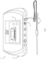
- an electroporation apparatus 1 comprises a main controller 2 linked with a user interface 3 and with a probe drive circuit 4, all mounted in a housing 9.
- the controller 2 and the interface 3 provide the user-side functions, whereas the drive circuit 4 provides the pulses to a probe 26.
- the drive circuit 4 comprises:
- the touch screen interface 3 is operably coupled to the controller 2 which manages the generation of the high voltages and the pulse control, and the voltage, pulse duration, polarity and orientation. This level of control is achieved via the series of control circuits in the blocks 5-8.
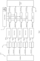
- the high voltage generator 6 is shown in Fig. 3 .
- the switch controller 5 which receives a low-voltage DC input of say 48 V. This input level sets the resultant pulse intensity level delivered to the probe 26, as described below.
- the switch controller 5 adjusts the time that the transformer primary 1 is energised to control the output voltage on the capacitors 14. Feedback from the output to the switch controller 5 (with suitable isolation through the medical grade optocoupler devices 18) enables the voltage to be precisely set and maintained.
- the capacitor 14 output voltage can be varied over a large range (typically 100V to about 1.5KV).
- the transformer 11, 12 steps up the input voltage to 1.5 kV in this example, which is rectified by a rectifier 13 of conventional construction.
- Each of the four capacitors 14 handles up to 450 V each in this example.
- the charge time is less than 10 seconds.
- the diodes 13 withstand the full output voltage plus the peak inverse voltage generated by switching in the transformer, which is typically several times the forward voltage. Also, the high voltage capacitors 14 are placed in series to enable operation at the required voltage, together with the resistors 15 in parallel with the capacitors help to balance the voltages across them. While only two windings 12 are shown on the output of the transformer for clarity, in practice this number may be higher. The preferred ranges for parameters of these components are 2 to 10.
- the high voltage generator 6 provides this level of DC voltage to the pulse switching controller 7, which in turn applies this voltage to the probe electrodes 26 via terminals 27 in a controlled pattern for optimal electroporation treatment. This is described in more detail below.
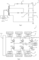
- the pulse switching controller 7 comprises seven top driver circuits and seven low driver circuits 22 each with a dedicated link to the power supply 20 (primarily the capacitors 14 of the high voltage generator 6).
- the first (left-most in Fig. 4 ) IGBT pair 24/25 connects the first probe electrode P1 to either the high voltage from the rail HV or to ground GND.
- the second IGBT pair - probe electrode P2 - would connect the opposite way to ground or the HV rail.
- a current is passed through the biological load in either direction.
- one probe electrode has either a high or a low (+1.5kV or -1.5kV) and its opposed electrode is grounded.
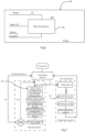
- a pulse switching control algorithm 100 is implemented by the controller 5 for the generation and application of the pulses.
- the probe drive sequence 100 the low side drivers 22 are turned on, followed by the high side drivers 22.
- the controller waits for the required pulse width and compensation time and then turns off the associated high side driver 22.
- the controller waits for the off-time and compensation time and turns off the low side drivers 22.
- a negative polarity pulse can then be produced if desired.
- the switching controller 5 interrogates the probe 26 to initially verify that it is approved and discovers the permitted pulse profile intended for the particular application.
- the probe identity is assessed and the appropriate pulse profile and sequence is defined.
- a sense wire actives the microcontroller by pulling the sense line low.
- the micro-controller can then communicate with the memory device 40 to read the probe parameters. Several copies of the parameters are stored in the probe memory 40 with error detection to verify a correct reading.
- the probe identity reading sequence as follows:
- Cancer cells display characteristic fractal patterns, with a solid tumour consisting of millions of these cells.
- the geometric shape of a solid tumour can be modelled as an ellipsoid ranging from oblate to prolate.
- small tumours can be treated in a single run at a single position, for tumours where its size is larger than the distance between the electrodes it is necessary to rotate electrodes around the tumour surface in order to maximize cell permeabilization and subsequently the treatment.
- the apparatus described here gives a usability and efficiency advantage, in that the number of probe repositioning steps are reduced due the electrical field being rotated around the tumour surface by the apparatus.
- the scheme illustrated in Fig. 8 is based on at least four probe electrodes arranged in a quadrangle and so defining a space in the transverse plane between them.
- Two electrodes defining one side of the quadrangle are positive (for example P1 and P7) while the two electrodes (for example P2 and P3) defining the opposed side are negative, and this state is immediately reversed. It is then performed in the orthogonal direction (for example P7 and P3 positive, P1 and P2 negative).
- the same patterns are repeated for the other quadrangles defined by the electrodes P1-P6-P5-P7 and by probes P5-P7-P3-P4).
- many of the electrodes play roles for different quadrangles.
- tissue between the electrode 26 is grouped into three zones bounded by the quadrangles, each of which is comprehensively treated with four approximately orthogonal charge directions through the tissue, as indicated by the arrows within the quadrangles in Fig. 8 .
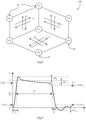
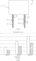
- Fig. 10 an image capture of representative pulses of a pair of opposed electrodes taken during the experiments included in Table 1 - 1000V, 2 ⁇ s bipolar pulse.
- ⁇ U s is not visible on this image due to the position of the electrodes and the impedance of the potato tissue.
- the circuit design is such that it minimises this dead-time.
- the oscilloscope shows the bipolar pulses (+1000V, - 1000V) in which the rise time and the fall time are sharp and the electroporation pulse amplitude stays at the expected level for the pulse duration.
- the features (U, tr, tf, U/2) of Fig. 9 can be identified in this image.
- the apparatus as described above may be used for various methods of treatment, either irreversible electroporation or reversible electroporation. Some of these methods may be performed with other electroporation apparatus known in the field, provided they can provide the electrical parameters indicated.
- electroporation is a medical and molecular biology technique in which an electric field is applied to cells or molecules in order to increase the permeability of the cell membrane, allowing chemicals, drugs, or DNA to be introduced into the cell. Electroporation has a number of possible medical fields of application, and can be used both reversibly and irreversibly. In a typical electroporation process, short and intense electric pulses are generated to transiently permeabilize the cell membrane.
- the electric field is below an electric field threshold and allows the cell membrane to repair after the treatment.
- Reversible electroporation may involve allowing a molecule, such as a drug or gene, into a cell or molecule that is normally not permeable for this substance without inducing cell death.
- the electric field threshold for a cell is individual for the cell.
- the electric field is greater than a particular electric field threshold, which creates permanent nanopores in the cell membrane, disrupting the cellular homeostasis and consequently forcing the cell to enter an irreversible cell death pathway such as via apoptotic or necrotic mechanisms.
- the pulse plateau (U) duration ( ⁇ t) is in the range of 1 ⁇ s to 5 ⁇ s, preferably 1 ⁇ s to 3 ⁇ s.
- the pulse plateau voltage amplitude (U) is in the range of 100V/cm to 3000V/cm, preferably 500V/cm to 2000V/cm.
- the individual pulse length may be in less than 1 ⁇ s and in the 0.03-0.99 ⁇ s range with the pulse plateau voltage amplitude (U) in the range of 5KV/cm to 50KV/cm, preferably 10KV/cm to 20KV/cm.
- the energized on-time duration of active treatment, in which the probe electrodes are pulsed is in the range of 100 ⁇ s to 300 ⁇ s, and the bipolar pulse frequency based on a cycle of two successive pulses is in the range of 100kHz to 500kHz.
- the electrodes may be driven so that current flow in the probe electrodes and the biological load is less than 500 mA for migration of DNA into permeabilized cells.
- a substance such as a liquid solution such as an hyperosmotic solution is injected to the site to assist a process of cell ablation, and said solution may include Calcium or potassium.
- a substance such as a liquid solution such as an hyperosmotic solution
- said solution may include Calcium or potassium.
- Calcium ions (Ca++) are injected directly into tissue at a concentration in the range of 2mMol/L to 250mMol/L and preferably in the range of 2mMol/L to 150mMol/L.
- the composition of the substance may be chosen at least in part to cause a desired level of tissue conductivity adjacent and between the electrodes.
- the substance may include deionised water for reduced conductivity.
- the substance may include a foam solution which preferentially elevates the resistance (Ohms) within the tissue environment in contrast with a more conductive liquid solution. As a result, the current (Amps) generated during delivery of the electroporation pulses is reduced in tissue where a foam solution has been injected, allowing for a safer and more effective treatment to be achieved.
- a solution comprising calcium ions (Ca++) with a concentration of between 2mMol/L to 150mMol/L may be injected for transient permeabilization by electroporation with an applied pulse voltage of 800 V/cm and 2000 V/cm; a pulse plateau duration of 1 ⁇ s to 3 ⁇ s, and a pulse number in the range of 1000 to 10,000.
- a solution with calcium ions is just one example. Others are given below.
- the monopolar pulse(s) for the higher voltage of 800V to 1600V may have a pulse duration in the range of 50 ⁇ s to 250 ⁇ s, preferably in the range of 100 ⁇ s to 200 ⁇ s.
- the voltage is more preferably in the range of 1000V/cm to 1200V/cm.
- the monopolar pulse(s) at the lower voltage of 1V/cm to 200V/cm may have a pulse duration of 10ms to 10s, preferably 20ms to 100ms. This voltage is preferably in the range of 100V/cm to 150V/cm.
- the second monopolar pulse(s) is preferably delivered within 1s of the first monopolar pulse(s).
- a drug is injected into the site and electroporation takes place for migration of the drug into the cells to cause cell ablation, for example chemotherapy agents.
- the controller after pulsed driving of the electrodes, discharges stored charge in a pulse of near zero duration followed by exponential decay.
- Opposed electrodes are inserted into the biological load at a separation of 1mm to 30mm, more preferably 1mm to 10mm, and more preferably 2mm to 8mm.
- the probe electrodes may be needle electrodes, but not necessarily.
- the controller of the electroporation apparatus which is used is programmed to provide high frequency operating parameters in the following ranges.
- a liquid solution injected locally to the target tissue aids irreversible electroporation and cell death, and enables lower voltage pulses to be effective in the high frequency drives outlined above.
- Such solutions may for example include Calcium ions to induce cell death.
- Calcium ions are injected intratumourally at a concentration in the range of 2mMol/L to 150mMol/L and preferably at the bottom end of this range due to the high frequency drive outlined above.
- a drug is injected into the site and electroporation takes place to enable intracellular passive diffusion of the drug.
- the drugs are chosen to cause cell death (ablation), for example chemotherapy agents.
- the passive diffusion of the chemotherapy agent is enabled by the effect of the high frequency electroporation and leads to cell death.
- the drugs may be Bleomycin or Cisplatin.
- Healthy biological tissue exhibits a different electrical impendence from abnormal and pre-cancerous tissue i.e. current flows more easily across abnormal and pre-cancerous tissue, and as such the measured impedance is lower than healthy biological tissue.
- the tissue impedance and changes in tissue impendence may in some examples be measured by the apparatus across a frequency spectrum.
- This allows the controller to automatically modify its operation and to generate user information to for example distinguish abnormal and pre-cancerous tissue from healthy tissue. This is done during treatment before a pulse is delivered and after a pulse is delivered, delivering diagnostic capability and can provide the treating health care professional with actionable feedback on the areas which have been treated and are to be treated. It also allows the controller to automatically adjust the voltage level to ensure that the current is not excessive, thereby automatically avoiding adverse effects of significantly reduced impedance.
- the controller measures the impedance by applying an AC signal to the tissue over a suitable frequency spectrum, typically from 1kHz to 100kHz. This is done immediately before and/or immediately active high-frequency electroporation driving.
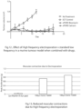
- Fig. 11 shows the effect of high frequency (2 ⁇ s bipolar (about 217KHz) vs. low-frequency (100 ⁇ s monopolar (1Hz), 70 ⁇ s monopolar (1Hz) electroporation pulses on Potato tissue. It illustrates tissue impedance as measured using a potato tissue model. A pair of probe needle electrodes were inserted 0.4cm apart and the tissue impedance pre and post electroporation delivery was measured (experiments conducted in triplicate).
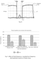
- Fig. 12 shows effect of high frequency (217KHz, 2 ⁇ s pulse plateau) electroporation vs. low frequency (1Hz) in a murine tumour model when combined with drugs.
- ECT Control Standard electroporation parameters with bleomycin (250IU) injected directly and using a total of 8, 100 ⁇ s polar pulses delivered at 1Hz with an applied field of 1000V/cm.
- ePORE Bleomycin (C) The pulses delivered as a bipolar pulse at a frequency of 217KHz. Bleomycin (250IU) was injected directly.
- ePORE Calcium (D) As above for ePORE bleomycin but using calcium injected intratumourally at a concentration of 9mg/ml and pulses delivered as a bipolar pulse at a frequency of 217KHz.
- the short ramp times ( ⁇ 0.25 ⁇ s to 1000V) enables more efficient uptake of large macromolecules and ions (including Ca++) directly across the cell membrane with the higher frequency allowing for more homogenous electrical field penetration through the cell membrane.
- uptake of DNA was achieved across the cell membrane utilising high frequency (>200KHz) bursts in combination with low current ( ⁇ 1Amp) pulses.
- a bipolar square wave high voltage high frequency burst of 1-2 ⁇ sec length bipolar x 50 (energised on time of 100-200 ⁇ s) followed within one minute by a unipolar square wave low voltage low current pulse of less than 5V ⁇ 250 ⁇ Amps for 1-10m duration.
- the apparatus results in enhanced DNA endocytosis and uptake leading to improved cell transfection and DNA expression.
- cell death is achieved through delivery of the high frequency electrical pulses (>200kHz) when delivered into a hyperosmotic solution.
- a hyperosmotic solution could be prepared from Sucrose, Glycerol, Xylose, Mannitol or Fructose at a concentration of between 125 and 300 mMol/L.
- Such a solution could also include up to 99mMol/L Ca2+ or Mg2+ or K+.
- a solution comprising calcium ions (Ca++) with a concentration of at least 2mMol/L in which the transient permeabilization is made by electroporation by 500-1500 V/cm; pulse length 0.1 ⁇ s -3 ⁇ s; pulse number 1000-10,000; and pulse frequency 200kHz to 500kHz.
- Ca++ calcium ions
- This diagram shows reduced muscular contractions due to high frequency electroporation by the apparatus 1.
- Accelerometer data was calculated from porcine tissue when electroporation was delivered to colorectal tissue. Muscular contractions were observed when using 1000V 2 ⁇ s bipolar pulses with a gap of less than 0.5 ⁇ s between each pulse (about 217kHz); using 1000V 2 ⁇ s bipolar pulses with a gap of 2 ⁇ s between each pulse (125KHz); using 100 ⁇ s monopolar pulses at 1000V (1Hz) and using 100 ⁇ s monopolar pulses at 1500V (1Hz). Peak acceleration observed at 217kHz was 0.04g; @ 125Hz was 0.08g; @1000V 100 ⁇ sec was 0.75g; @1500V 100 ⁇ sec was 0.83g.
- the apparatus drives a pulse to one pair of probe electrodes with a ramp-up, a plateau, and a ramp-down sequence.
- Each of the ramp durations is less than 0.5 ⁇ s or preferably less than 0.25 ⁇ s due to the short turn-on time of the switches used and the fact that they are driven by individual driver circuits 22.
- the controller drives at least some pulses with a ramp-up as described above, however the plateau is set to 0, before turning off the switches to achieve the pulse, thereby achieving an exponential decaying pulse.
- the capacitors are charged as normal and then the pulse is activated, letting it discharge freely.
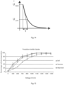
- the decay rate as shown in Fig. 14 is controlled by the value of the balance resistors 15 and the capacitors 14.
- the controller drives the electrodes to an amplitude of U max and then turns off the pulse - i.e. sets the pulse duration to 0.
- the electroporation apparatus for some of the treatment time drives the pulses with a decaying exponential shape.
- This operation may be of benefit after high frequency operation. It effectively discharges the capacitors
- Flow cytometry using a propidium iodide marker was used to determine the relationship between electroporation effectiveness / cell permeabilization and the medium used as a buffer for the cells.
- the field strength (V/cm, the distance being the separation of the electrodes) was adjusted from 500V/cm to 1400V/cm at 100V intervals and a determination made on the degree of PI uptake and consequently cell permeabilization.
- the FacsCaliburTM apparatus has the capacity to quantify fluorescence in individual cells, which varies depending upon the efficacy of electroporation (i.e., number of pores open in the cell membrane due to electroporation-allowing entry of PI into the cell nucleus, resulting in detectable fluorescence from the cell).
- the FACSCaliburTM flow cytometer with CELLQUESTTM software was used for analysis of cell size and fluorescence. Cell samples were obtained during the completion of the electroporation experiments. In brief, the measured ratio of electroporated to non-electroporated cells was calculated as follows. The ⁇ Collection Criteria' were set at the position of ⁇ Event Count or Time' in the Acquisition and Storage dialog box and the acquisition time was selected. The flow rate was set and the "Voltage”, "Amps gain”, and threshold were adjusted to ensure that the cells could be detected. Forward scatter (FSC) and side scatter (SSC) were collected in linear mode and FL2 (PI Fluorescence) set in log mode. Acquisition of data could not start until the sample volt- age became stable.
- FSC Forward scatter
- SSC side scatter
- FL2 PI Fluorescence
- the substance may be in the form of a foam, being a liquid with very small bubbles of a gas.
- a foam may be used to enhance the permeabilization effect of electroporation, with particularly beneficial results for high frequency electroporation (greater than 100KHz).
- Use of a foam is described in more detail below.
- the relative concentrations of liquid and gas in the foam are expressed by volume at atmospheric pressure, such as in a syringe when loaded with air and liquid.
- the foam may be formed by any suitable means, and indeed it may be done manually by the clinician in a syringe.
- a major benefit of utilising a foam for direct injection into the target tissue to be electroporated is that it can act as a carrier if required for the molecule of choice while its impact on tissue conductivity relative to a liquid is superior in that it minimises increases in the conductivity.
- the air or gas component of the foam bubbles have minimal conductivity relative to a liquid and enable a more favourable environment particularly in the case of high frequency (>100kHz) pulses, minimising the current delivered and aiding in enhanced cell permeabilization.
- Fig. 16 shows the impedance and current comparisons using a liquid compared to a foam.
- a liquid has a lower impedance (higher conductivity) and results in a higher current (A) delivered.
- a foam has a higher impedance/resistance and lower conductivity, resulting in a lower current (A) delivered.
- the pulse width may be in a range wider than described above, in some cases in a range as low as 0.05 ⁇ s, and the voltage may in some cases be greater than 10KV/cm.
- FIG. 17 shows cell permeabilization from 0% to 100% when increasing the electrical field applied (V/cm).
- V/cm electrical field applied
- Fig. 18 shows expected cell survival against increasing electrical field (V/cm). Low conductivity results in cell death occurring at a lower field strength compared to the high conductivity buffer.
- Non-foamed liquid when injected is rapidly diluted by the circulating blood volume.
- the interaction with blood decreases the efficacy of the liquid solution, due to binding with plasma proteins that ultimately reduces the number of active molecules.
- a foam is able to displace blood rather than mixing with it, increasing the contact time of a higher concentration of active agent with the tissue and thus resulting in greater efficacy. With foam, a lower concentration of agent can be used to obtain the same therapeutic effect as in their liquid counterpart, reducing the prevalence of side effects associated with higher concentrations.
- a foam due to the presence of bubbles of a gas such as air, is less conductive than the corresponding liquid solution and consequently results in lower currents, higher cell permeabilization and less pain sensation for the patient.
- Foam may in some examples be created by mixing albumin, gas, and a liquid solution, for example in a ratio of 1:4:1 by volume.
- the ratio of gas (room air or CO2 gas for example) to liquid is in a range of 1:2 to 1:10 by volume.
- the foam used includes one or more of the following: Albumin, human serum albumin; concentration 10-50% preferably 15-30% by volume Polidocanol (0.5-5% by volume) or Sodium Tetradecyl Sulfate (STS) (0.5-5% by volume).
- Polidocanol 0.5-5% by volume
- STS and Polidocanol are sclerosing agents individually, whereas Albumin is not Polidocanol is also a local anaesthetic.
- Albumin is a foaming agent solely whereas Polidocanol and STS are both foaming and sclerosing agents (they are an irritant and induce cell death directly).
- Active agents may include one or more of: Calcium ions, Ca++ (2mMol to 150mMol); Potassium (2mMol to 100mMol); Bleomycin; Cisplatin; DNA; and/or RNA.
- the electroporation pulses advantageously have parameters as follows: bipolar pulses 0.05 ⁇ s to 5 ⁇ s pulse lengths delivered in trains with an 'on' energised time per train of 0.1 ⁇ s to1000 ⁇ s repeated up to 1000 times at a frequency of 1kHz to 1000KHz.
- Conductivity increases around the cell are caused in part by the volume of fluid in the area and the local injection of an electroporation solution, which may include a treatment molecule of choice (Calcium, Potassium, Bleomycin, Cisplatin etc) and a large concentration of ions.
- an electroporation solution which may include a treatment molecule of choice (Calcium, Potassium, Bleomycin, Cisplatin etc) and a large concentration of ions.
- a foam being made largely of gas or air is less conductive than the corresponding liquid solution and consequently results in lower currents, higher cell permeabilization and less pain sensation for the patient.
- Pulse Voltage V/cm Pulse duration Frequen cy Hz Number of Pulses Charge Delivered Pulse Type Electrochemothera py (ECT) 500-1500 50 -100 ⁇ sec 1-5000 4-8 N/A Monopolar or Bipolar Square wave
- Irreversible electroporation IRE 1500-3000 70-100 ⁇ sec 0.5-10 90-200 N/A Monopolar Square wave
- Electroporation and Electrolysis E2 100-3000 ⁇ sec-millisecond s N/A N/A >100 ⁇ F Exponential ly decaying wave DNA/RNA delivery 1-1000 ⁇ sec-millisecond s N/A N/A N/A Monopolar Square wave
- a foam may also be utilised to facilitate dispersion of a local anaesthetic into the tissue to be treated.
- the local anaesthetic may be lignocaine 5-20 mg/ml with or without adrenaline.
- Mepivacaine 10 to 30mg/ml is another example of a local anaesthetic that could be used.
- the foam and local anaesthetic could be administrated in combination with a molecule of choice e.g. calcium or potassium ions, bleomycin, DNA; or it could be provided alone.
- an injection apparatus is used to deliver the substance to the target tissue via a needle electrode that can also facilitate homogenous distribution of an injected substance via 'pores' or openings along its conductive length.
- the apparatus, 200 comprises a reservoir 201 and an array of needles 202 with walls 203 and pores 204.
- the reservoir 201 comprises a pump of any desired type, such as a peristaltic pump or a syringe.
- the needle gauge size is preferably in the range of 14GA to 30GA (0.3mm to 2.1mm outer diameter; 0.15mm to 1.8mm inner diameter).
- the needles have a maximum internal width dimension in the range of 0.1mm to 1.8mm and a maximum external width dimension in the range of 0.25mm to 2.5mm. 90, and preferably the openings have a maximum width dimension in the range of 0.05mm to 1.5mm, and preferably the separation of a needle to the closest needle is in the range of 2mm to 3cm.
- the openings may be in the form of slots or holes of any desired shape to achieve the desired flow and distribution of injected substance.
- the needles may have an insulating sleeve to cover openings and/or to insulate electrically where voltage is not to be applied to the patient tissue.
- a sleeve, either insulated or not, may be removed after delivery of the substance and prior to pulsing.
- the pattern of the openings is preferably spiral (staggered) as shown in Fig. 19 .
- the number of openings may be distributed unevenly, being weighted more towards the needle side facing the other needle(s)/electrode(s) to help ensure that most of the volume is distributed in the space between the electrodes.
- Depth indicators may be used to communicate the depth of the openings with respect to the tissue depth.
- the probe head 200 may be used with a pulse generator as described above, or with a known third-party electroporation generator.
- the needles may all be connected to the same pump or reservoir, or may have independent pumps or valving arrangements to allow different substances be delivered through different needles.
- One or more needle may have its own solid trocar tip.
- the injected substance may be a foam, but it could alternatively be a liquid-only substance such as a non-conductive substance, for example deionised water.
- Test data demonstrates that in a viable test tissue (animal liver) we evaluated the current generated during delivery of electroporation pulses with increasing voltage.
- the total energised ⁇ on time' of the pulses was 6ms.
- a reduction in the current generated per pulse delivered was approximately 40% when foam was injected into the tissue just prior to pulsing.
- Fig. 20 shows that in tests there is a major reduction in electroporation current for a given pulse voltage amplitude. In this plot the current units are Amps.
- the electrodes deliver the electrical pulses and also deliver the substance (liquid-only or foam) to tissue via the pores 204.
- This enables more homogenous delivery of the substance in the environment around the electrode.
- it allows application of a co-ordinated substance delivery and pulsing method which may be controlled in an optimum manner by an electronic controller instructing the pulse generator and pumps and/or valves for substance delivery to needles.
- a co-ordinated substance delivery and pulsing method which may be controlled in an optimum manner by an electronic controller instructing the pulse generator and pumps and/or valves for substance delivery to needles.
- the first substance may be a foam with a relatively high level of gas bubbles
- the post-pulsing solution may contain a therapeutic agent such as calcium, potassium, bleomycin or cisplatin or DNA or RNA.
- the pores 204 deliver a foam or other substance such as a non-conductive solution e.g. deionized water directly into the tissue just prior to the electroporation pulse delivery and in doing so will reduce the current that would be generated otherwise.
- a higher current generated during a procedure will negatively impact on the efficacy of the electroporation pulses to porate the tissue.
- Generation of high currents also presents technical and safety challenges such as current ⁇ arcing', tissue burning and pulse termination pre-procedure completion to protect the patient and the generator.
- the needle electrodes 202 with pores 204 may be used to deliver a non-conductive solution just prior to delivery of the electrical pulses; additionally, the same electrodes may be used to administrate a therapeutic solution immediately once the electrical pulses have been delivered.
- the needle electrode(s) are positioned in the target tissue and, in part based on impedance feedback, will inject a foam (or other solution) directly into the target tissue via the pores in the needle electrode(s). This is followed immediately by the delivery of the electrical pulses via the same needle electrode and there may be a post electroporation injection of a therapeutic substance directly via the needle electrode, for example a calcium or chemotherapeutic solution.
- Fig. 19 there are two electrodes, positive and negative. In other examples there may be a bipolar single electrode where the negative and positive polarity are delivered on the same electrode. Alternatively, there may be more than 2 electrodes in an array such as described above with reference to Fig. 8 .
- the invention achieves very effective electroporation with minimal risk of patient discomfort.
- the following summarises some of the benefits.
- the apparatus provides high frequency pulses with the aim of cell membrane and internal organelle permeabilization, causing ablation alone or in combination with a locally injected agent/molecule.
- uptake of Calcium with a low concentration of injected Calcium as a liquid or foam, in a range of 2 to 150 mMol/L, preferably towards the lower end of this range.
- high frequency pulses generate a reduced current by utilising a foam in the environment to be treated.
- the apparatus achieves safe delivery of high voltage, ultra-short pulses (0.1 ⁇ s to 5.0 ⁇ s range) to human or animal subjects, whilst negating inefficiencies inherent to switch-mode transformer design.
- the apparatus also achieves delivery of ultrashort pulses ( ⁇ sec's) into a hyperosmotic solution enabling more efficient cell electroporation.
- the apparatus enables combination of ultrashort pulses ( ⁇ tsec's) with sharp turn-on and turn-off times to maximise synergy with a consequent capacitance discharge in the range of 10-500 ⁇ F to induce localised cell death. It is particularly beneficial that the plateau is stable for significant but short duration of 1 ⁇ s to 3 ⁇ s, thereby achieving very effective treatment in a short energized on time.
- the apparatus' and methods achieve accurate coverage of tissue with sufficiently large electric field, avoiding the problem of uneven electric field distribution in tumour tissue due to its heterogeneity.
Landscapes
- Health & Medical Sciences (AREA)
- Life Sciences & Earth Sciences (AREA)
- Engineering & Computer Science (AREA)
- General Health & Medical Sciences (AREA)
- Biomedical Technology (AREA)
- Bioinformatics & Cheminformatics (AREA)
- Zoology (AREA)
- Organic Chemistry (AREA)
- Chemical & Material Sciences (AREA)
- Wood Science & Technology (AREA)
- Genetics & Genomics (AREA)
- Biotechnology (AREA)
- Public Health (AREA)
- Physics & Mathematics (AREA)
- Veterinary Medicine (AREA)
- Animal Behavior & Ethology (AREA)
- Nuclear Medicine, Radiotherapy & Molecular Imaging (AREA)
- Surgery (AREA)
- Microbiology (AREA)
- Cell Biology (AREA)
- Radiology & Medical Imaging (AREA)
- Electromagnetism (AREA)
- Biochemistry (AREA)
- General Engineering & Computer Science (AREA)
- Biophysics (AREA)
- Sustainable Development (AREA)
- Plasma & Fusion (AREA)
- Otolaryngology (AREA)
- Heart & Thoracic Surgery (AREA)
- Medical Informatics (AREA)
- Molecular Biology (AREA)
- Electrotherapy Devices (AREA)
- Pharmaceuticals Containing Other Organic And Inorganic Compounds (AREA)
- Measuring Leads Or Probes (AREA)
Priority Applications (1)
| Application Number | Priority Date | Filing Date | Title |
|---|---|---|---|
| EP24190953.0A EP4427693A3 (de) | 2019-09-02 | 2020-09-01 | Elektroporationsvorrichtung und -verfahren |
Applications Claiming Priority (5)
| Application Number | Priority Date | Filing Date | Title |
|---|---|---|---|
| EP19194958 | 2019-09-02 | ||
| EP19194959 | 2019-09-02 | ||
| EP20168567 | 2020-04-07 | ||
| PCT/EP2020/074374 WO2021043779A1 (en) | 2019-09-02 | 2020-09-01 | An electroporation apparatus and method |
| EP20767504.2A EP4025144B1 (de) | 2019-09-02 | 2020-09-01 | Elektroporationsgerät |
Related Parent Applications (2)
| Application Number | Title | Priority Date | Filing Date |
|---|---|---|---|
| EP20767504.2A Division EP4025144B1 (de) | 2019-09-02 | 2020-09-01 | Elektroporationsgerät |
| EP20767504.2A Division-Into EP4025144B1 (de) | 2019-09-02 | 2020-09-01 | Elektroporationsgerät |
Related Child Applications (2)
| Application Number | Title | Priority Date | Filing Date |
|---|---|---|---|
| EP24190953.0A Division-Into EP4427693A3 (de) | 2019-09-02 | 2020-09-01 | Elektroporationsvorrichtung und -verfahren |
| EP24190953.0A Division EP4427693A3 (de) | 2019-09-02 | 2020-09-01 | Elektroporationsvorrichtung und -verfahren |
Publications (4)
| Publication Number | Publication Date |
|---|---|
| EP4230718A2 true EP4230718A2 (de) | 2023-08-23 |
| EP4230718A3 EP4230718A3 (de) | 2023-10-18 |
| EP4230718B1 EP4230718B1 (de) | 2024-09-04 |
| EP4230718C0 EP4230718C0 (de) | 2024-09-04 |
Family
ID=72355964
Family Applications (3)
| Application Number | Title | Priority Date | Filing Date |
|---|---|---|---|
| EP23185028.0A Active EP4230718B1 (de) | 2019-09-02 | 2020-09-01 | Elektroporationsvorrichtung |
| EP24190953.0A Pending EP4427693A3 (de) | 2019-09-02 | 2020-09-01 | Elektroporationsvorrichtung und -verfahren |
| EP20767504.2A Active EP4025144B1 (de) | 2019-09-02 | 2020-09-01 | Elektroporationsgerät |
Family Applications After (2)
| Application Number | Title | Priority Date | Filing Date |
|---|---|---|---|
| EP24190953.0A Pending EP4427693A3 (de) | 2019-09-02 | 2020-09-01 | Elektroporationsvorrichtung und -verfahren |
| EP20767504.2A Active EP4025144B1 (de) | 2019-09-02 | 2020-09-01 | Elektroporationsgerät |
Country Status (5)
| Country | Link |
|---|---|
| US (3) | US11912975B2 (de) |
| EP (3) | EP4230718B1 (de) |
| JP (2) | JP7543410B2 (de) |
| CN (1) | CN114340723B (de) |
| WO (1) | WO2021043779A1 (de) |
Families Citing this family (10)
| Publication number | Priority date | Publication date | Assignee | Title |
|---|---|---|---|---|
| CA3000878A1 (en) | 2015-10-07 | 2017-04-13 | Mayo Foundation For Medical Education And Research | Electroporation for obesity or diabetes treatment |
| WO2021043779A1 (en) * | 2019-09-02 | 2021-03-11 | Mirai Medical Limited | An electroporation apparatus and method |
| CA3158414A1 (en) | 2019-10-21 | 2021-04-29 | Endogenex, Inc. | Devices, systems, and methods for pulsed electric field treatment of the duodenum |
| US12076071B2 (en) | 2020-08-14 | 2024-09-03 | Kardium Inc. | Systems and methods for treating tissue with pulsed field ablation |
| US20250160920A1 (en) | 2022-02-28 | 2025-05-22 | Mirai Medical Ltd | An electroporation device |
| EP4493077A4 (de) * | 2022-03-15 | 2025-04-30 | Mayo Foundation for Medical Education and Research | Gewebeverschiebungsschaum |
| EP4580533A1 (de) | 2022-09-02 | 2025-07-09 | Mirai Medical Limited | Elektroporationssonde und vorrichtung |
| CN116269733B (zh) * | 2023-03-20 | 2024-05-03 | 成都飞云科技有限公司 | 一种脉冲消融导管、装置及脉冲消融方法 |
| WO2024235826A1 (en) | 2023-05-12 | 2024-11-21 | Mirai Medical Limited | A method and apparatus for electroporation |
| WO2025046258A1 (en) * | 2023-08-26 | 2025-03-06 | Abdolahad Mohammad | Electroporation/electrochemotherapy of surgically sensitive regions |
Citations (2)
| Publication number | Priority date | Publication date | Assignee | Title |
|---|---|---|---|---|
| US20060089674A1 (en) | 2002-04-16 | 2006-04-27 | Walters Richard E | Method of treating biological materials with translating electrical fields and electrode polarity reversal |
| WO2018200800A1 (en) | 2017-04-27 | 2018-11-01 | Farapulse, Inc. | Systems, devices, and methods for signal generation |
Family Cites Families (39)
| Publication number | Priority date | Publication date | Assignee | Title |
|---|---|---|---|---|
| GB9302335D0 (en) * | 1993-02-05 | 1993-03-24 | Macdonald Alexander J R | Electrotherapeutic apparatus |
| US5702359A (en) | 1995-06-06 | 1997-12-30 | Genetronics, Inc. | Needle electrodes for mediated delivery of drugs and genes |
| US5869326A (en) * | 1996-09-09 | 1999-02-09 | Genetronics, Inc. | Electroporation employing user-configured pulsing scheme |
| JP4740503B2 (ja) * | 2000-01-27 | 2011-08-03 | 株式会社モレニアムラボラトリーズ | 分子導入装置及び分子導入方法 |
| EP1448770A1 (de) * | 2001-11-27 | 2004-08-25 | Cellectricon AB | Verfahren zur kombinierten sequentiellen zuführung von agentien und elektroporation für zellstrukturen und verwendung davon |
| JP4810425B2 (ja) * | 2003-07-18 | 2011-11-09 | イースタン バージニア メディカル スクール | 電気パルスを発生するための装置および該装置を使用する方法 |
| FR2861997A1 (fr) * | 2003-11-06 | 2005-05-13 | Fred Zacouto | Stimulateur cardiaque orthorythmique inotrope |
| CZ2006315A3 (cs) | 2003-11-17 | 2006-10-11 | Btg International Limited | Terapeutická pena |
| FR2893256B1 (fr) * | 2005-11-14 | 2008-08-15 | Yves Scherman | Generateur d'impulsions electriques unipolaires. |
| EP2162182A1 (de) | 2007-06-15 | 2010-03-17 | Transport Pharmaceuticals, Inc. | Verfahren und system zur verringerung der stromkonzentration bei der elektrokinetischen arzneiabgabe |
| US7830158B2 (en) * | 2007-12-28 | 2010-11-09 | 3M Innovative Properties Company | Time-sloped capacitance measuring circuits and methods |
| US11254926B2 (en) * | 2008-04-29 | 2022-02-22 | Virginia Tech Intellectual Properties, Inc. | Devices and methods for high frequency electroporation |
| US10448989B2 (en) * | 2009-04-09 | 2019-10-22 | Virginia Tech Intellectual Properties, Inc. | High-frequency electroporation for cancer therapy |
| US10238447B2 (en) * | 2008-04-29 | 2019-03-26 | Virginia Tech Intellectual Properties, Inc. | System and method for ablating a tissue site by electroporation with real-time monitoring of treatment progress |
| JP5774480B2 (ja) * | 2008-07-18 | 2015-09-09 | マックスサイト インコーポレーティッド | 電気穿孔を最適化するための方法 |
| US8221411B2 (en) | 2008-07-28 | 2012-07-17 | Medtronic, Inc. | Systems and methods for cardiac tissue electroporation ablation |
| EP2221086A1 (de) * | 2009-02-24 | 2010-08-25 | Enrico Spugnini | Tragbare Ausrüstung mit Generatorschaltung und Versorger für den therapeutischen Transfer von Molekülen mittels Elektroporation |
| US11382681B2 (en) | 2009-04-09 | 2022-07-12 | Virginia Tech Intellectual Properties, Inc. | Device and methods for delivery of high frequency electrical pulses for non-thermal ablation |
| US10232173B2 (en) * | 2009-04-16 | 2019-03-19 | Vgx Pharmaceuticals, Llc | Contactless electropermeabilization electrode and method |
| IT1394143B1 (it) * | 2009-05-04 | 2012-05-25 | Igea S P A | Dispositivo per elettroporazione reversibile atto ad indurre apoptosi cellulare |
| WO2014106258A1 (en) * | 2012-12-31 | 2014-07-03 | Cold Plasma Medical Technologies, Inc. | Cold plasma electroporation of medication and associated methods |
| WO2016017045A1 (ja) | 2014-07-28 | 2016-02-04 | ネッパジーン株式会社 | エレクトロポレーター用電気パルス発生器及び前記電気パルス発生器を備えたエレクトロポレーター装置 |
| DK3277368T3 (da) * | 2015-03-31 | 2020-07-27 | Oncosec Medical Inc | Systemer til forbedret vævsregistreringsbaseret elektroporering |
| US10117702B2 (en) | 2015-04-10 | 2018-11-06 | Ethicon Llc | Surgical generator systems and related methods |
| EP3288471A1 (de) * | 2015-05-01 | 2018-03-07 | Inter Science GmbH | Verfahren, systeme und vorrichtungen zur gewebeablation mithilfe von impulsformdesigns |
| EP3399933B1 (de) * | 2016-01-05 | 2021-09-01 | Farapulse, Inc. | Systeme zur abgabe von gepulster elektrischer feldablationsenergie an endokardiales gewebe |
| US20170246468A1 (en) * | 2016-02-25 | 2017-08-31 | EP Technologies LLC | Methods and systems for controlling or tuning the electric field generated in skin or tissue during cold plasma skin treatments |
| US10188449B2 (en) | 2016-05-23 | 2019-01-29 | Covidien Lp | System and method for temperature enhanced irreversible electroporation |
| US10589092B2 (en) * | 2016-06-07 | 2020-03-17 | The Board Of Trustees Of The Leland Stanford Junior University | Methods for enhancing and modulating reversible and irreversible electroporation lesions by manipulating pulse waveforms |
| GB2563386A (en) | 2017-06-08 | 2018-12-19 | Creo Medical Ltd | Electrosurgical instrument |
| CN119074196A (zh) | 2018-05-07 | 2024-12-06 | 波士顿科学医学有限公司 | 用于过滤由脉冲电场消融诱导的高压噪声的系统、设备和方法 |
| WO2021043779A1 (en) * | 2019-09-02 | 2021-03-11 | Mirai Medical Limited | An electroporation apparatus and method |
| US11065047B2 (en) | 2019-11-20 | 2021-07-20 | Farapulse, Inc. | Systems, apparatuses, and methods for protecting electronic components from high power noise induced by high voltage pulses |
| US11540877B2 (en) | 2019-12-03 | 2023-01-03 | Biosense Webster (Israel) Ltd. | Pulse generator for irreversible electroporation |
| WO2022020478A1 (en) | 2020-07-24 | 2022-01-27 | Boston Scientific Scimed Inc | Electric field application for single shot cardiac ablation by irreversible electroporation |
| US11638819B2 (en) | 2020-09-11 | 2023-05-02 | Galvanize Therapeutics, Inc. | Signal generators for use with tissue modification systems |
| US11389234B1 (en) | 2021-02-11 | 2022-07-19 | Boston Scientific Scimed, Inc. | Systems, apparatuses, and methods for pre-ablation pulses in pulsed field ablation applications |
| WO2022173939A1 (en) | 2021-02-12 | 2022-08-18 | Boston Scientific Scimed Inc | Pulse sequence for cardiac ablation by irreversible electroporation with low skeletal muscle stimulation |
| US11824542B1 (en) | 2022-06-29 | 2023-11-21 | Eagle Harbor Technologies, Inc. | Bipolar high voltage pulser |
-
2020
- 2020-09-01 WO PCT/EP2020/074374 patent/WO2021043779A1/en not_active Ceased
- 2020-09-01 EP EP23185028.0A patent/EP4230718B1/de active Active
- 2020-09-01 EP EP24190953.0A patent/EP4427693A3/de active Pending
- 2020-09-01 CN CN202080061620.XA patent/CN114340723B/zh active Active
- 2020-09-01 US US17/636,649 patent/US11912975B2/en active Active
- 2020-09-01 JP JP2022539775A patent/JP7543410B2/ja active Active
- 2020-09-01 EP EP20767504.2A patent/EP4025144B1/de active Active
-
2023
- 2023-10-18 US US18/381,368 patent/US12152229B2/en active Active
-
2024
- 2024-08-20 JP JP2024139058A patent/JP2024161544A/ja active Pending
- 2024-10-15 US US18/916,015 patent/US20250034505A1/en active Pending
Patent Citations (2)
| Publication number | Priority date | Publication date | Assignee | Title |
|---|---|---|---|---|
| US20060089674A1 (en) | 2002-04-16 | 2006-04-27 | Walters Richard E | Method of treating biological materials with translating electrical fields and electrode polarity reversal |
| WO2018200800A1 (en) | 2017-04-27 | 2018-11-01 | Farapulse, Inc. | Systems, devices, and methods for signal generation |
Non-Patent Citations (2)
| Title |
|---|
| B. L. IBEY ET AL.: "Bipolar nanosecond electric pulses are less efficient at elecropermeabilization and killing cells than monopolar pulses", BIOCHEM. BIOPHYS. RES. COMMUN., vol. 443, no. 2, January 2014 (2014-01-01), pages 568073, XP055575014, DOI: 10.1016/j.bbrc.2013.12.004 |
| POLAJZER TDERMOL-CERNE JREBERSEK MO'CONNOR RMIKLAVCIC D: "Cancellation effect is present in high-frequency reversible and irreversible electroporation", BIOELECTROCHEMISTRY, vol. 132, April 2020 (2020-04-01), pages 107442 |
Also Published As
| Publication number | Publication date |
|---|---|
| US20250034505A1 (en) | 2025-01-30 |
| EP4230718B1 (de) | 2024-09-04 |
| EP4025144A1 (de) | 2022-07-13 |
| US20240076599A1 (en) | 2024-03-07 |
| EP4025144C0 (de) | 2023-09-06 |
| US20220298464A1 (en) | 2022-09-22 |
| US11912975B2 (en) | 2024-02-27 |
| JP2024161544A (ja) | 2024-11-19 |
| JP7543410B2 (ja) | 2024-09-02 |
| EP4427693A3 (de) | 2024-10-16 |
| EP4230718C0 (de) | 2024-09-04 |
| CN114340723A (zh) | 2022-04-12 |
| US12152229B2 (en) | 2024-11-26 |
| WO2021043779A1 (en) | 2021-03-11 |
| CN114340723B (zh) | 2025-09-26 |
| EP4230718A3 (de) | 2023-10-18 |
| EP4025144B1 (de) | 2023-09-06 |
| EP4427693A2 (de) | 2024-09-11 |
| JP2022547233A (ja) | 2022-11-10 |
Similar Documents
| Publication | Publication Date | Title |
|---|---|---|
| EP4025144B1 (de) | Elektroporationsgerät | |
| US10994133B2 (en) | Methods for enhancing and modulating reversible and irreversible electroporation lesions by manipulating pulse waveforms | |
| US11464968B2 (en) | Stacked potential electroporation | |
| EP0925647B1 (de) | Elektroporationsgerät mit benutzerkonfigurierten impulsen | |
| US20250195128A1 (en) | Methods, systems, and apparatuses for tissue ablation using a modulated exponential decay pulse | |
| CA3118718C (en) | Megahertz compression of nanosecond pulse bursts | |
| US6937890B2 (en) | Nonpenetrating electroporation device | |
| KR102548891B1 (ko) | 전기천공과 전기분해를 이용한 세포사멸 촉진 장치 | |
| HK40052647B (zh) | 纳秒脉冲突发的兆赫压缩 | |
| HK40052647A (en) | Megahertz compression of nanosecond pulse bursts |
Legal Events
| Date | Code | Title | Description |
|---|---|---|---|
| PUAI | Public reference made under article 153(3) epc to a published international application that has entered the european phase |
Free format text: ORIGINAL CODE: 0009012 |
|
| STAA | Information on the status of an ep patent application or granted ep patent |
Free format text: STATUS: THE APPLICATION HAS BEEN PUBLISHED |
|
| AC | Divisional application: reference to earlier application |
Ref document number: 4025144 Country of ref document: EP Kind code of ref document: P |
|
| AK | Designated contracting states |
Kind code of ref document: A2 Designated state(s): AL AT BE BG CH CY CZ DE DK EE ES FI FR GB GR HR HU IE IS IT LI LT LU LV MC MK MT NL NO PL PT RO RS SE SI SK SM TR |
|
| REG | Reference to a national code |
Ref country code: DE Ref legal event code: R079 Free format text: PREVIOUS MAIN CLASS: C12M0001420000 Ref country code: DE Ref legal event code: R079 Ref document number: 602020037380 Country of ref document: DE Free format text: PREVIOUS MAIN CLASS: C12M0001420000 Ipc: A61B0018120000 |
|
| PUAL | Search report despatched |
Free format text: ORIGINAL CODE: 0009013 |
|
| AK | Designated contracting states |
Kind code of ref document: A3 Designated state(s): AL AT BE BG CH CY CZ DE DK EE ES FI FR GB GR HR HU IE IS IT LI LT LU LV MC MK MT NL NO PL PT RO RS SE SI SK SM TR |
|
| RIC1 | Information provided on ipc code assigned before grant |
Ipc: A61B 18/00 20060101ALN20230914BHEP Ipc: A61B 18/14 20060101ALI20230914BHEP Ipc: C12M 1/42 20060101ALI20230914BHEP Ipc: A61N 1/32 20060101ALI20230914BHEP Ipc: A61B 18/12 20060101AFI20230914BHEP |
|
| STAA | Information on the status of an ep patent application or granted ep patent |
Free format text: STATUS: REQUEST FOR EXAMINATION WAS MADE |
|
| 17P | Request for examination filed |
Effective date: 20240212 |
|
| RBV | Designated contracting states (corrected) |
Designated state(s): AL AT BE BG CH CY CZ DE DK EE ES FI FR GB GR HR HU IE IS IT LI LT LU LV MC MK MT NL NO PL PT RO RS SE SI SK SM TR |
|
| GRAP | Despatch of communication of intention to grant a patent |
Free format text: ORIGINAL CODE: EPIDOSNIGR1 |
|
| STAA | Information on the status of an ep patent application or granted ep patent |
Free format text: STATUS: GRANT OF PATENT IS INTENDED |
|
| RIC1 | Information provided on ipc code assigned before grant |
Ipc: A61B 18/00 20060101ALN20240315BHEP Ipc: A61B 18/14 20060101ALI20240315BHEP Ipc: C12M 1/42 20060101ALI20240315BHEP Ipc: A61N 1/32 20060101ALI20240315BHEP Ipc: A61B 18/12 20060101AFI20240315BHEP |
|
| INTG | Intention to grant announced |
Effective date: 20240403 |
|
| GRAS | Grant fee paid |
Free format text: ORIGINAL CODE: EPIDOSNIGR3 |
|
| GRAA | (expected) grant |
Free format text: ORIGINAL CODE: 0009210 |
|
| STAA | Information on the status of an ep patent application or granted ep patent |
Free format text: STATUS: THE PATENT HAS BEEN GRANTED |
|
| AC | Divisional application: reference to earlier application |
Ref document number: 4025144 Country of ref document: EP Kind code of ref document: P |
|
| AK | Designated contracting states |
Kind code of ref document: B1 Designated state(s): AL AT BE BG CH CY CZ DE DK EE ES FI FR GB GR HR HU IE IS IT LI LT LU LV MC MK MT NL NO PL PT RO RS SE SI SK SM TR |
|
| REG | Reference to a national code |
Ref country code: GB Ref legal event code: FG4D |
|
| REG | Reference to a national code |
Ref country code: CH Ref legal event code: EP |
|
| REG | Reference to a national code |
Ref country code: IE Ref legal event code: FG4D |
|
| REG | Reference to a national code |
Ref country code: DE Ref legal event code: R096 Ref document number: 602020037380 Country of ref document: DE |
|
| U01 | Request for unitary effect filed |
Effective date: 20240916 |
|
| U07 | Unitary effect registered |
Designated state(s): AT BE BG DE DK EE FI FR IT LT LU LV MT NL PT RO SE SI Effective date: 20241007 |
|
| PG25 | Lapsed in a contracting state [announced via postgrant information from national office to epo] |
Ref country code: NO Free format text: LAPSE BECAUSE OF FAILURE TO SUBMIT A TRANSLATION OF THE DESCRIPTION OR TO PAY THE FEE WITHIN THE PRESCRIBED TIME-LIMIT Effective date: 20241204 |
|
| PG25 | Lapsed in a contracting state [announced via postgrant information from national office to epo] |
Ref country code: GR Free format text: LAPSE BECAUSE OF FAILURE TO SUBMIT A TRANSLATION OF THE DESCRIPTION OR TO PAY THE FEE WITHIN THE PRESCRIBED TIME-LIMIT Effective date: 20241205 |
|
| PG25 | Lapsed in a contracting state [announced via postgrant information from national office to epo] |
Ref country code: HR Free format text: LAPSE BECAUSE OF FAILURE TO SUBMIT A TRANSLATION OF THE DESCRIPTION OR TO PAY THE FEE WITHIN THE PRESCRIBED TIME-LIMIT Effective date: 20240904 |
|
| PG25 | Lapsed in a contracting state [announced via postgrant information from national office to epo] |
Ref country code: ES Free format text: LAPSE BECAUSE OF FAILURE TO SUBMIT A TRANSLATION OF THE DESCRIPTION OR TO PAY THE FEE WITHIN THE PRESCRIBED TIME-LIMIT Effective date: 20240904 |
|
| PG25 | Lapsed in a contracting state [announced via postgrant information from national office to epo] |
Ref country code: NO Free format text: LAPSE BECAUSE OF FAILURE TO SUBMIT A TRANSLATION OF THE DESCRIPTION OR TO PAY THE FEE WITHIN THE PRESCRIBED TIME-LIMIT Effective date: 20241204 Ref country code: HR Free format text: LAPSE BECAUSE OF FAILURE TO SUBMIT A TRANSLATION OF THE DESCRIPTION OR TO PAY THE FEE WITHIN THE PRESCRIBED TIME-LIMIT Effective date: 20240904 Ref country code: GR Free format text: LAPSE BECAUSE OF FAILURE TO SUBMIT A TRANSLATION OF THE DESCRIPTION OR TO PAY THE FEE WITHIN THE PRESCRIBED TIME-LIMIT Effective date: 20241205 Ref country code: ES Free format text: LAPSE BECAUSE OF FAILURE TO SUBMIT A TRANSLATION OF THE DESCRIPTION OR TO PAY THE FEE WITHIN THE PRESCRIBED TIME-LIMIT Effective date: 20240904 |
|
| PG25 | Lapsed in a contracting state [announced via postgrant information from national office to epo] |
Ref country code: IS Free format text: LAPSE BECAUSE OF FAILURE TO SUBMIT A TRANSLATION OF THE DESCRIPTION OR TO PAY THE FEE WITHIN THE PRESCRIBED TIME-LIMIT Effective date: 20250104 |
|
| PG25 | Lapsed in a contracting state [announced via postgrant information from national office to epo] |
Ref country code: SM Free format text: LAPSE BECAUSE OF FAILURE TO SUBMIT A TRANSLATION OF THE DESCRIPTION OR TO PAY THE FEE WITHIN THE PRESCRIBED TIME-LIMIT Effective date: 20240904 |
|
| PG25 | Lapsed in a contracting state [announced via postgrant information from national office to epo] |
Ref country code: CZ Free format text: LAPSE BECAUSE OF FAILURE TO SUBMIT A TRANSLATION OF THE DESCRIPTION OR TO PAY THE FEE WITHIN THE PRESCRIBED TIME-LIMIT Effective date: 20240904 Ref country code: PL Free format text: LAPSE BECAUSE OF FAILURE TO SUBMIT A TRANSLATION OF THE DESCRIPTION OR TO PAY THE FEE WITHIN THE PRESCRIBED TIME-LIMIT Effective date: 20240904 |
|
| PG25 | Lapsed in a contracting state [announced via postgrant information from national office to epo] |
Ref country code: SK Free format text: LAPSE BECAUSE OF FAILURE TO SUBMIT A TRANSLATION OF THE DESCRIPTION OR TO PAY THE FEE WITHIN THE PRESCRIBED TIME-LIMIT Effective date: 20240904 |
|
| PLBE | No opposition filed within time limit |
Free format text: ORIGINAL CODE: 0009261 |
|
| STAA | Information on the status of an ep patent application or granted ep patent |
Free format text: STATUS: NO OPPOSITION FILED WITHIN TIME LIMIT |
|
| 26N | No opposition filed |
Effective date: 20250605 |
|
| U20 | Renewal fee for the european patent with unitary effect paid |
Year of fee payment: 6 Effective date: 20250722 |
|
| PGFP | Annual fee paid to national office [announced via postgrant information from national office to epo] |
Ref country code: GB Payment date: 20250722 Year of fee payment: 6 |
|
| PGFP | Annual fee paid to national office [announced via postgrant information from national office to epo] |
Ref country code: IE Payment date: 20250722 Year of fee payment: 6 |