EP4230592A1 - Bushing and method for producing glass fiber - Google Patents
Bushing and method for producing glass fiber Download PDFInfo
- Publication number
- EP4230592A1 EP4230592A1 EP21894377.7A EP21894377A EP4230592A1 EP 4230592 A1 EP4230592 A1 EP 4230592A1 EP 21894377 A EP21894377 A EP 21894377A EP 4230592 A1 EP4230592 A1 EP 4230592A1
- Authority
- EP
- European Patent Office
- Prior art keywords
- nozzle
- nozzles
- bushing
- row
- nozzle row
- Prior art date
- Legal status (The legal status is an assumption and is not a legal conclusion. Google has not performed a legal analysis and makes no representation as to the accuracy of the status listed.)
- Pending
Links
- 239000003365 glass fiber Substances 0.000 title claims abstract description 27
- 238000004519 manufacturing process Methods 0.000 title claims abstract description 13
- 239000006060 molten glass Substances 0.000 claims abstract description 41
- 239000011521 glass Substances 0.000 claims description 28
- 235000019592 roughness Nutrition 0.000 claims description 17
- 238000000034 method Methods 0.000 claims 1
- 230000000052 comparative effect Effects 0.000 description 24
- 238000001816 cooling Methods 0.000 description 12
- 239000000463 material Substances 0.000 description 10
- 230000000694 effects Effects 0.000 description 5
- 238000011156 evaluation Methods 0.000 description 5
- BASFCYQUMIYNBI-UHFFFAOYSA-N platinum Chemical compound [Pt] BASFCYQUMIYNBI-UHFFFAOYSA-N 0.000 description 4
- 238000012986 modification Methods 0.000 description 3
- 230000004048 modification Effects 0.000 description 3
- 229910000510 noble metal Inorganic materials 0.000 description 3
- KDLHZDBZIXYQEI-UHFFFAOYSA-N Palladium Chemical compound [Pd] KDLHZDBZIXYQEI-UHFFFAOYSA-N 0.000 description 2
- 229910001260 Pt alloy Inorganic materials 0.000 description 2
- 229910045601 alloy Inorganic materials 0.000 description 2
- 239000000956 alloy Substances 0.000 description 2
- 239000004744 fabric Substances 0.000 description 2
- 238000005259 measurement Methods 0.000 description 2
- 229910052697 platinum Inorganic materials 0.000 description 2
- KJTLSVCANCCWHF-UHFFFAOYSA-N Ruthenium Chemical compound [Ru] KJTLSVCANCCWHF-UHFFFAOYSA-N 0.000 description 1
- BQCADISMDOOEFD-UHFFFAOYSA-N Silver Chemical compound [Ag] BQCADISMDOOEFD-UHFFFAOYSA-N 0.000 description 1
- 238000000137 annealing Methods 0.000 description 1
- 239000004566 building material Substances 0.000 description 1
- 239000002826 coolant Substances 0.000 description 1
- 230000008021 deposition Effects 0.000 description 1
- 238000010586 diagram Methods 0.000 description 1
- 238000005553 drilling Methods 0.000 description 1
- 239000012776 electronic material Substances 0.000 description 1
- 230000002708 enhancing effect Effects 0.000 description 1
- 239000000835 fiber Substances 0.000 description 1
- PCHJSUWPFVWCPO-UHFFFAOYSA-N gold Chemical compound [Au] PCHJSUWPFVWCPO-UHFFFAOYSA-N 0.000 description 1
- 229910052737 gold Inorganic materials 0.000 description 1
- 239000010931 gold Substances 0.000 description 1
- 238000010438 heat treatment Methods 0.000 description 1
- 229910052741 iridium Inorganic materials 0.000 description 1
- GKOZUEZYRPOHIO-UHFFFAOYSA-N iridium atom Chemical compound [Ir] GKOZUEZYRPOHIO-UHFFFAOYSA-N 0.000 description 1
- 229910052762 osmium Inorganic materials 0.000 description 1
- SYQBFIAQOQZEGI-UHFFFAOYSA-N osmium atom Chemical compound [Os] SYQBFIAQOQZEGI-UHFFFAOYSA-N 0.000 description 1
- 229910052763 palladium Inorganic materials 0.000 description 1
- PXXKQOPKNFECSZ-UHFFFAOYSA-N platinum rhodium Chemical compound [Rh].[Pt] PXXKQOPKNFECSZ-UHFFFAOYSA-N 0.000 description 1
- 229910052703 rhodium Inorganic materials 0.000 description 1
- 239000010948 rhodium Substances 0.000 description 1
- MHOVAHRLVXNVSD-UHFFFAOYSA-N rhodium atom Chemical compound [Rh] MHOVAHRLVXNVSD-UHFFFAOYSA-N 0.000 description 1
- 229910052707 ruthenium Inorganic materials 0.000 description 1
- 229910052709 silver Inorganic materials 0.000 description 1
- 239000004332 silver Substances 0.000 description 1
- 238000004513 sizing Methods 0.000 description 1
- 238000004804 winding Methods 0.000 description 1
Images

Classifications
-
- C—CHEMISTRY; METALLURGY
- C03—GLASS; MINERAL OR SLAG WOOL
- C03B—MANUFACTURE, SHAPING, OR SUPPLEMENTARY PROCESSES
- C03B37/00—Manufacture or treatment of flakes, fibres, or filaments from softened glass, minerals, or slags
- C03B37/08—Bushings, e.g. construction, bushing reinforcement means; Spinnerettes; Nozzles; Nozzle plates
- C03B37/083—Nozzles; Bushing nozzle plates
-
- C—CHEMISTRY; METALLURGY
- C03—GLASS; MINERAL OR SLAG WOOL
- C03B—MANUFACTURE, SHAPING, OR SUPPLEMENTARY PROCESSES
- C03B37/00—Manufacture or treatment of flakes, fibres, or filaments from softened glass, minerals, or slags
- C03B37/01—Manufacture of glass fibres or filaments
- C03B37/02—Manufacture of glass fibres or filaments by drawing or extruding, e.g. direct drawing of molten glass from nozzles; Cooling fins therefor
Definitions
- the present invention relates to a bushing and a method for producing glass fiber.
- bushings including a base plate and a plurality of nozzles provided at a bottom surface of the base plate are used for producing glass fiber.
- Patent Document 1 JP 2015-231926 A
- the base plate has been reduced in size by arranging adjacent nozzles closer to each other.
- molten glass that flows out from the nozzles tends to adhere between adjacent nozzles or the like.
- An object of the present invention is to provide a bushing that allows molten glass to be stably drawn out from nozzles provided in a small-sized base plate, and a method for producing glass fiber.
- a bushing to solve the above problem includes a base plate and a nozzle group provided at a bottom surface of the base plate.
- the nozzle group includes a first nozzle row in which a plurality of first nozzles are aligned and a second nozzle row in which a plurality of second nozzles are aligned, the second nozzle row being arranged adjacent to the first nozzle row.
- the bushing is configured to satisfy the following relations (1) to (6) where, for each of the plurality of first nozzles and the plurality of second nozzles, D1 is a nozzle hole inner diameter [mm], Lt is a nozzle flow path length [mm], A1 is a nozzle hole cross-sectional area [mm 2 ], A2 is a nozzle wall cross-sectional area [mm 2 ], L1 is an interval [mm] between the centers of adjacent first nozzles in the first nozzle row and an interval [mm] between the centers of adjacent second nozzles in the second nozzle row, and L2 is an interval [mm] between the center of the first nozzle row in a row width direction and the center of the second nozzle row in the row width direction.
- Y is equal to or greater than y1
- a space around the nozzle can be suitably secured in accordance with the outlet velocity of the molten glass flowing out from the nozzle.
- adhesion of the molten glass, flowing out from the nozzle, between adjacent nozzles or the like can be suppressed.
- Y is equal to or less than y2
- the space around the nozzle does not become excessively large with respect to the outlet velocity of the molten glass flowing out from the nozzle.
- an increase in the production cost of the bushing can be suppressed.
- the bushing is preferably configured to further satisfy the following relation (7). 0.2 ⁇ X ⁇ 3.0
- the molten glass can be more stably drawn out from the nozzles.
- a mean value of arithmetic mean roughnesses Ra at an inner surface of a nozzle hole of each of the plurality of first nozzles and the plurality of second nozzles is preferably 2 ⁇ m or less. According to this configuration, the outlet velocity of the molten glass flowing out from the nozzle can be made further uniform. Thus, adhesion of the molten glass, flowing out from the nozzle, between adjacent nozzles or the like can be suppressed.
- a method for producing glass fiber includes supplying molten glass to a bushing, drawing out a plurality of glass filaments from the bushing, and then gathering the plurality of glass filaments into a strand.
- the bushing includes a base plate and a nozzle group provided at a bottom surface of the base plate.
- the nozzle group includes a first nozzle row in which a plurality of first nozzles are aligned and a second nozzle row in which a plurality of second nozzles are aligned, the second nozzle row being arranged adjacent to the first nozzle row.
- D1 is a nozzle hole inner diameter [mm]
- Lt is a nozzle flow path length [mm]
- A1 is a nozzle hole cross-sectional area [mm 2 ]
- A2 is a nozzle wall cross-sectional area [mm 2 ]
- L1 is an interval [mm] between the centers of adjacent first nozzles in the first nozzle row and an interval [mm] between the centers of adjacent second nozzles in the second nozzle row
- L2 is an interval [mm] between the center of the first nozzle row in a row width direction and the center of the second nozzle row in the row width direction.
- molten glass can be stably drawn out from nozzles provided in a small-sized base plate.
- a bushing 11 is used for producing glass fiber (glass strand GS).
- a glass fiber producing apparatus includes the bushing 11, an applicator 12 for sizing a large number of glass filaments GF drawn out from the bushing 11, and a gathering shoe 13 for gathering the large number of sized glass filaments GF into a strand. The large number of glass filaments GF are gathered by the gathering shoe 13 to obtain a glass strand GS.
- the glass fiber producing apparatus includes a collet 14 for winding the glass strand GS. The glass strand GS is wound around the collet 14 to obtain a cake CA.
- the glass fiber producing apparatus includes a traverse for reciprocating the glass strand GS.
- the bushing 11 includes a bushing body 11a to which molten glass MG is supplied, and a base plate 11b provided at a bottom of the bushing body 11a.
- the bushing body 11a includes a supply port through which the molten glass MG is supplied, a screen for suppressing deposition of foreign matter on the base plate 11b, and a terminal for resistance heating.
- the bushing 11 includes a nozzle group provided at a bottom surface 11b1 of the base plate 11b.
- the molten glass MG is supplied to the nozzles N, and glass filaments GF are drawn out from the nozzles N.
- the number of nozzles is preferably 800 to 10000, and more preferably 2000 to 8000. In the figure, the nozzle group of the bushing 11 is illustrated in a simplified manner.
- the nozzle group of the bushing 11 includes a first nozzle row R1 in which a plurality of first nozzles N1 are aligned and a second nozzle row R2 in which a plurality of second nozzles N2 are aligned.
- the second nozzle row R2 is arranged adjacent to the first nozzle row R1.
- an alignment direction of the plurality of first nozzles N1 and the plurality of second nozzles N2 is a horizontal direction along the Y-axis direction in FIG. 2 .
- the first nozzle row R1 and the second nozzle row R2 are arranged adjacent to each other horizontally along the X-axis direction orthogonal to the Y-axis direction in FIG. 2 .
- a nozzle hole inner diameter [mm] is represented by D1
- a nozzle flow path length [mm] is represented by Lt
- a nozzle hole cross-sectional area [mm 2 ] is represented by A1
- a nozzle wall cross-sectional area [mm 2 ] is represented by A2.
- the first nozzles N1 and the second nozzles N2 have flow paths extending in the vertical direction along the Z-axis direction in FIGS. 2 and 3 .
- the nozzle flow path length Lt is a length from an upper surface 11b2 of the base plate 11b to a tip of the nozzle N. That is, the nozzle flow path length Lt [mm] is a sum of a thickness Lt1 [mm] of the base plate 11b and a length Lt2 [mm] from the bottom surface 11b1 of the base plate 11b to the tip of the nozzle N.
- the nozzle hole cross-sectional area A1 [mm 2 ] and the nozzle wall cross-sectional area A2 [mm 2 ] are horizontal cross-sectional areas of the nozzle N as indicated by dotted patterns in FIG. 2 .
- the nozzle hole cross-sectional area A1 is constant over the entire nozzle flow path length Lt for each nozzle N, and the nozzle wall cross-sectional area A2 is constant over the entire length of each nozzle N.
- a cross-sectional shape of the nozzle hole is circular, and the glass filament GF having a circular cross-section is drawn out from the nozzle hole.
- L1 represents an interval [mm] between the centers of adjacent first nozzles N1 in the first nozzle row R1 and an interval [mm] between the centers of adjacent second nozzles N2 in the second nozzle row R2.
- L2 represents an interval [mm] between the center of the first nozzle row R1 in a row width direction and the center of the second nozzle row R2 in the row width direction.
- L2 represents an interval [mm] between the center of one of the first nozzles N1 and the center of the second nozzle N2 located closest to this nozzle N1, that is, the interval [mm] between the centers of the first nozzle N1 and the second nozzle N2 adjacent to each other.
- a straight line passing through the center of the first nozzle row R1 in the row width direction and a straight line passing through the center of the second nozzle row R2 in the row width direction are parallel.
- the row width direction of the first nozzle row R1 is a direction parallel to the bottom surface 11b1 of the base plate 11b and orthogonal to the alignment direction of the first nozzles N1, and coincides with the X-axis direction, for example, in FIGS. 2 and 3 .
- the row width direction of the second nozzle row R2 is a direction parallel to the bottom surface 11b1 of the base plate 11b and orthogonal to the alignment direction of the second nozzles N2, and coincides with the X-axis direction, for example, in FIGS. 2 and 3 .
- the relation (4) above is an equation for obtaining a numerical value representing the degree of outlet velocity of the molten glass MG flowing out from the nozzle N.
- the larger the nozzle hole inner diameter D1 the faster the outlet velocity of the molten glass MG.
- the shorter the nozzle flow path length Lt the faster the outlet velocity of the molten glass MG.
- the relation (5) above is an equation for obtaining a value representing a size of a space around one nozzle N.
- each nozzle arrangement area A3 indicated by the dotted pattern in FIG. 2 that is, an area of one nozzle N and the space around the nozzle N in a bottom view of the bushing 11 can be obtained by the relation (6) above.
- the area of the space around one nozzle N can be obtained by subtracting the nozzle hole cross-sectional area A1 and the nozzle wall cross-sectional area A2 from the nozzle arrangement area A3.
- the nozzle hole inner diameter D1 [mm] is, for example, preferably in a range of 0.5 mm or more and 3.0 mm or less, and more preferably in a range of 0.8 mm or more and 2.0 mm or less.
- the nozzle flow path length Lt [mm] is preferably in a range of 1.5 mm or more and 8.0 mm or less, and more preferably in a range of 2.5 mm or more and 6.0 mm or less.
- the nozzle hole cross-sectional area A1 [mm 2 ] is preferably in a range of 0.2 mm 2 or more and 7.0 mm 2 or less, and more preferably in a range of 0.5 mm 2 or more and 5.0 mm 2 or less.
- the nozzle wall cross-sectional area A2 [mm 2 ] is preferably in a range of 0.6 mm 2 or more and 4.9 mm 2 or less, and more preferably in a range of 0.8 mm 2 or more and 3.5 mm 2 or less.
- the bushing 11 is preferably configured to further satisfy the following relation (7), for example, from the viewpoint of more stably drawing out the molten glass MG from the nozzles N. 0.2 ⁇ X ⁇ 3.0
- a mean value of arithmetic mean roughnesses Ra at an inner surface Ns of the nozzle hole of each of the first nozzles N1 and the second nozzles N2 is preferably 2 ⁇ m or less.
- This mean value of the arithmetic mean roughnesses Ra is more preferably 0.1 ⁇ m or more, and still more preferably in a range of 0.3 ⁇ m or more and 1.5 ⁇ m or less.
- the mean value of the arithmetic mean roughnesses Ra at the inner surface Ns of the nozzle hole can be adjusted by a shape of a drill used for drilling the nozzle hole or vibration of the drill.
- the mean value of the arithmetic mean roughnesses Ra at the inner surface Ns of the nozzle hole can also be adjusted by bringing a drill into contact with the inner surface Ns of the nozzle hole or annealing the inner surface Ns of the nozzle hole.
- the mean value of the arithmetic mean roughnesses Ra is a value in an unused state before the molten glass MG is caused to flow.
- the mean value of the arithmetic mean roughnesses Ra can be measured as follows.
- a plurality of nozzles N are manufactured under the same manufacturing conditions, and then a nozzle N to be measured is extracted as a sample from the plurality of nozzles N. Subsequently, the extracted sample is cut along a direction in which a hole axis of the nozzle hole extends (the direction corresponding to the Z-axis direction in the bushing 11). Subsequently, the arithmetic mean roughness Ra of the inner surface Ns of the nozzle hole is measured along the direction in which the hole axis extends in accordance with JIS B 0601:2001.
- arithmetic mean roughness Ra For the measurement of the arithmetic mean roughness Ra, Surfcoder (manufactured by Kosaka Laboratory Ltd., product name: ET4000) is used. The measurement distance is 1 mm. The arithmetic mean roughness Ra is measured at six different positions.
- a mean value of the arithmetic mean roughnesses Ra measured at the six positions is taken as the mean value of the arithmetic mean roughnesses Ra of the inner surface Ns.
- the nozzles N other than the sample for which the arithmetic mean roughnesses Ra were measured are regarded as having the same mean value as the mean value of the arithmetic mean roughnesses Ra in the sample.
- the bushing 11 of the present embodiment further includes a plurality of cooling members 15 provided at the bottom surface 11b1 of the base plate 11b.
- the cooling members 15 cool the molten glass MG drawn out from the nozzles N.
- Examples of the cooling member 15 include a cooling fin and a cooling pipe having a flow path through which a cooling medium flows.
- Each cooling member 15 has a longitudinal direction and is arranged extending along the first nozzle row R1 and the second nozzle row R2.
- the plurality of cooling members 15 are arranged at predetermined intervals.
- two nozzle rows, the first nozzle row R1 and the second nozzle row R2 are arranged between the adjacent cooling members 15. But three or more nozzle rows may be arranged between the adjacent cooling members 15.
- Examples of materials for the bushing body 11a, the base plate 11b, the nozzles N, and the cooling members 15 include noble metals and noble metal alloys.
- the noble metal is gold, silver, platinum, palladium, rhodium, iridium, ruthenium, or osmium.
- the materials for the bushing body 11a, the base plate 11b, the nozzles N, and the cooling members 15 are preferably platinum or a platinum alloy from the viewpoint of enhancing durability. Examples of the platinum alloy include a platinumrhodium alloy.
- the glass strand GS is produced by supplying the molten glass MG to the bushing 11 described above, drawing out the plurality of glass filaments GF from the bushing 11, and then gathering the plurality of glass filaments GF into a strand.
- the viscosity of the molten glass MG at the forming temperature at which the glass filaments GF are formed is preferably in a range of from 10 2.0 to 10 3.5 dPa ⁇ s, and more preferably in a range of from 10 2.5 to 10 3.3 dPa ⁇ s.
- the viscosity of the molten glass MG refers to the viscosity of the molten glass at a position where the molten glass flows into the nozzles N.
- Examples of the form of the glass fiber include the cake CA in which the glass strand GS is wound.
- the glass strand GS can be used as, for example, chopped strands cut to a predetermined length, milled fibers, rovings, yarns, mats, fabrics, tapes, or braided fabrics.
- Examples of applications of the glass fiber include vehicle applications, electronic material applications, building material applications, civil engineering applications, aircraft-related applications, shipbuilding applications, logistics applications, industrial machinery applications, and daily necessities applications.
- glass fibers were produced using bushings having the values of X and the values of Y shown in Tables 1 and 2.
- the number of nozzles of the bushing is 100.
- the mean value of the arithmetic mean roughnesses Ra at the inner surface of the nozzle hole is 1.5 ⁇ m.
- the viscosity of the molten glass at the forming temperature at which the glass filaments are formed is 10 3.0 dPa ⁇ s.
- the velocity at which the glass filaments are formed is in a range of 800 [m/min] or more and 3000 [m/min] or less.
- Comparative Examples 1 to 16 glass fibers were produced in the same manner as in Examples 1 to 50, except that bushings having the values of X and the values of Y shown in Table 3 were used.
- Glass strands were produced continuously for 30 days using the bushings of Examples 1 to 50 and the bushings of Comparative Examples 1 to 16.
- the productivity of the glass fiber was evaluated using the following evaluation criteria. The evaluation results are shown in Tables 1 to 3.
- FIG. 4 shows a graph in which the values of X and the values of Y are plotted for the bushings of all examples in Tables 1 to 3.
- the bushings of Examples 1 to 50 are indicated by “circles", and the bushings of Comparative Examples 1 to 16 are indicated by "triangles".
- the straight line of the foregoing relation (2) is indicated by a solid line
- the straight line of the foregoing relation (3) is indicated by a dashed line. From this graph, it can be seen that the bushings of Examples 1 to 50 have configurations that fall within the range represented by the foregoing relation (1).
- the bushings of Comparative Examples 1 to 16 have configurations that fall outside the range represented by the foregoing relation (1).
- the bushings of Examples 1 to 50 were evaluated to have high productivity of the glass fiber.
- the bushings of Comparative Examples 2, 3, 6, 8, 10, 12, 13, and 15 were evaluated to have low productivity of the glass fiber.
- the bushings of Comparative Examples 1, 4, 5, 7, 9, 11, 14, and 16 cannot suitably reduce the amount of the material used for the base plate because the space around the nozzle is excessively large for the outlet velocity of the molten glass flowing out from the nozzle.
Landscapes
- Engineering & Computer Science (AREA)
- Chemical & Material Sciences (AREA)
- Life Sciences & Earth Sciences (AREA)
- General Life Sciences & Earth Sciences (AREA)
- Geochemistry & Mineralogy (AREA)
- Manufacturing & Machinery (AREA)
- Materials Engineering (AREA)
- Organic Chemistry (AREA)
- Manufacture, Treatment Of Glass Fibers (AREA)
- Spinning Methods And Devices For Manufacturing Artificial Fibers (AREA)
Abstract
Description
- The present invention relates to a bushing and a method for producing glass fiber.
- As disclosed in
Patent Document 1, bushings including a base plate and a plurality of nozzles provided at a bottom surface of the base plate are used for producing glass fiber. - Patent Document 1:
JP 2015-231926 A - In the bushings as described above, from the viewpoint of reducing the amount of material used for the base plate, the base plate has been reduced in size by arranging adjacent nozzles closer to each other. However, with such small-sized bushings, molten glass that flows out from the nozzles tends to adhere between adjacent nozzles or the like. When the molten glass adheres between adjacent nozzles or the like, it becomes difficult to stably draw out the molten glass from the nozzles, and for example, glass filaments are more likely to break.
- An object of the present invention is to provide a bushing that allows molten glass to be stably drawn out from nozzles provided in a small-sized base plate, and a method for producing glass fiber.
- A bushing to solve the above problem includes a base plate and a nozzle group provided at a bottom surface of the base plate. The nozzle group includes a first nozzle row in which a plurality of first nozzles are aligned and a second nozzle row in which a plurality of second nozzles are aligned, the second nozzle row being arranged adjacent to the first nozzle row. The bushing is configured to satisfy the following relations (1) to (6) where, for each of the plurality of first nozzles and the plurality of second nozzles, D1 is a nozzle hole inner diameter [mm], Lt is a nozzle flow path length [mm], A1 is a nozzle hole cross-sectional area [mm2], A2 is a nozzle wall cross-sectional area [mm2], L1 is an interval [mm] between the centers of adjacent first nozzles in the first nozzle row and an interval [mm] between the centers of adjacent second nozzles in the second nozzle row, and L2 is an interval [mm] between the center of the first nozzle row in a row width direction and the center of the second nozzle row in the row width direction.


- According to this configuration, since Y is equal to or greater than y1, a space around the nozzle can be suitably secured in accordance with the outlet velocity of the molten glass flowing out from the nozzle. Thus, adhesion of the molten glass, flowing out from the nozzle, between adjacent nozzles or the like can be suppressed. In addition, since Y is equal to or less than y2, the space around the nozzle does not become excessively large with respect to the outlet velocity of the molten glass flowing out from the nozzle. Thus, an increase in the production cost of the bushing can be suppressed.
- The bushing is preferably configured to further satisfy the following relation (7).

- According to this configuration, the molten glass can be more stably drawn out from the nozzles.
- In the bushing, a mean value of arithmetic mean roughnesses Ra at an inner surface of a nozzle hole of each of the plurality of first nozzles and the plurality of second nozzles is preferably 2 µm or less. According to this configuration, the outlet velocity of the molten glass flowing out from the nozzle can be made further uniform. Thus, adhesion of the molten glass, flowing out from the nozzle, between adjacent nozzles or the like can be suppressed.
- A method for producing glass fiber includes supplying molten glass to a bushing, drawing out a plurality of glass filaments from the bushing, and then gathering the plurality of glass filaments into a strand. The bushing includes a base plate and a nozzle group provided at a bottom surface of the base plate. The nozzle group includes a first nozzle row in which a plurality of first nozzles are aligned and a second nozzle row in which a plurality of second nozzles are aligned, the second nozzle row being arranged adjacent to the first nozzle row. The foregoing relations (1) to (6) are satisfied where, for each of the plurality of first nozzles and the plurality of second nozzles, D1 is a nozzle hole inner diameter [mm], Lt is a nozzle flow path length [mm], A1 is a nozzle hole cross-sectional area [mm2], and A2 is a nozzle wall cross-sectional area [mm2], L1 is an interval [mm] between the centers of adjacent first nozzles in the first nozzle row and an interval [mm] between the centers of adjacent second nozzles in the second nozzle row, and L2 is an interval [mm] between the center of the first nozzle row in a row width direction and the center of the second nozzle row in the row width direction.
- According to the present invention, molten glass can be stably drawn out from nozzles provided in a small-sized base plate.
-
-
FIG. 1 is a schematic diagram illustrating a glass fiber producing apparatus according to an embodiment. -
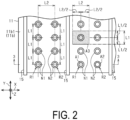
FIG. 2 is a bottom view of part of a bushing. -
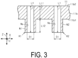
FIG. 3 is a partial cross-sectional view taken along the line 3-3 inFIG. 2 . -
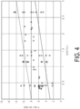
FIG. 4 is a graph showing a relationship between parameters relating to dimensions of a nozzle and parameters relating to arrangement of the nozzles. - An embodiment of a bushing and a method for producing glass fiber will be described below with reference to the accompanying drawings.
- As illustrated in
FIG. 1 , abushing 11 is used for producing glass fiber (glass strand GS). A glass fiber producing apparatus includes thebushing 11, anapplicator 12 for sizing a large number of glass filaments GF drawn out from thebushing 11, and agathering shoe 13 for gathering the large number of sized glass filaments GF into a strand. The large number of glass filaments GF are gathered by thegathering shoe 13 to obtain a glass strand GS. The glass fiber producing apparatus includes acollet 14 for winding the glass strand GS. The glass strand GS is wound around thecollet 14 to obtain a cake CA. Although not illustrated, the glass fiber producing apparatus includes a traverse for reciprocating the glass strand GS. - The
bushing 11 includes a bushing body 11a to which molten glass MG is supplied, and abase plate 11b provided at a bottom of the bushing body 11a. Although not illustrated, the bushing body 11a includes a supply port through which the molten glass MG is supplied, a screen for suppressing deposition of foreign matter on thebase plate 11b, and a terminal for resistance heating. - The
bushing 11 includes a nozzle group provided at a bottom surface 11b1 of thebase plate 11b. The molten glass MG is supplied to the nozzles N, and glass filaments GF are drawn out from the nozzles N. The number of nozzles is preferably 800 to 10000, and more preferably 2000 to 8000. In the figure, the nozzle group of thebushing 11 is illustrated in a simplified manner. - As illustrated in
FIG. 2 , the nozzle group of thebushing 11 includes a first nozzle row R1 in which a plurality of first nozzles N1 are aligned and a second nozzle row R2 in which a plurality of second nozzles N2 are aligned. The second nozzle row R2 is arranged adjacent to the first nozzle row R1. Specifically, an alignment direction of the plurality of first nozzles N1 and the plurality of second nozzles N2 is a horizontal direction along the Y-axis direction inFIG. 2 . The first nozzle row R1 and the second nozzle row R2 are arranged adjacent to each other horizontally along the X-axis direction orthogonal to the Y-axis direction inFIG. 2 . - As illustrated in
FIGS. 2 and3 , for each of the first nozzles N1 and the second nozzles N2, a nozzle hole inner diameter [mm] is represented by D1, a nozzle flow path length [mm] is represented by Lt, a nozzle hole cross-sectional area [mm2] is represented by A1, and a nozzle wall cross-sectional area [mm2] is represented by A2. The first nozzles N1 and the second nozzles N2 have flow paths extending in the vertical direction along the Z-axis direction inFIGS. 2 and3 . - As illustrated in
FIG. 3 , the nozzle flow path length Lt is a length from an upper surface 11b2 of thebase plate 11b to a tip of the nozzle N. That is, the nozzle flow path length Lt [mm] is a sum of a thickness Lt1 [mm] of thebase plate 11b and a length Lt2 [mm] from the bottom surface 11b1 of thebase plate 11b to the tip of the nozzle N. The nozzle hole cross-sectional area A1 [mm2] and the nozzle wall cross-sectional area A2 [mm2] are horizontal cross-sectional areas of the nozzle N as indicated by dotted patterns inFIG. 2 . In the present embodiment, the nozzle hole cross-sectional area A1 is constant over the entire nozzle flow path length Lt for each nozzle N, and the nozzle wall cross-sectional area A2 is constant over the entire length of each nozzle N. A cross-sectional shape of the nozzle hole is circular, and the glass filament GF having a circular cross-section is drawn out from the nozzle hole. - The
bushing 11 is configured to satisfy the following relations (1) to (6).


- Here, L1 represents an interval [mm] between the centers of adjacent first nozzles N1 in the first nozzle row R1 and an interval [mm] between the centers of adjacent second nozzles N2 in the second nozzle row R2. L2 represents an interval [mm] between the center of the first nozzle row R1 in a row width direction and the center of the second nozzle row R2 in the row width direction. In other words, L2 represents an interval [mm] between the center of one of the first nozzles N1 and the center of the second nozzle N2 located closest to this nozzle N1, that is, the interval [mm] between the centers of the first nozzle N1 and the second nozzle N2 adjacent to each other. A straight line passing through the center of the first nozzle row R1 in the row width direction and a straight line passing through the center of the second nozzle row R2 in the row width direction are parallel. The row width direction of the first nozzle row R1 is a direction parallel to the bottom surface 11b1 of the
base plate 11b and orthogonal to the alignment direction of the first nozzles N1, and coincides with the X-axis direction, for example, inFIGS. 2 and3 . The row width direction of the second nozzle row R2 is a direction parallel to the bottom surface 11b1 of thebase plate 11b and orthogonal to the alignment direction of the second nozzles N2, and coincides with the X-axis direction, for example, inFIGS. 2 and3 . - The relation (4) above is an equation for obtaining a numerical value representing the degree of outlet velocity of the molten glass MG flowing out from the nozzle N. The larger the nozzle hole inner diameter D1, the faster the outlet velocity of the molten glass MG. On the other hand, the shorter the nozzle flow path length Lt, the faster the outlet velocity of the molten glass MG.
- The relation (5) above is an equation for obtaining a value representing a size of a space around one nozzle N. Specifically, each nozzle arrangement area A3 indicated by the dotted pattern in
FIG. 2 , that is, an area of one nozzle N and the space around the nozzle N in a bottom view of thebushing 11 can be obtained by the relation (6) above. In the relation (5), the area of the space around one nozzle N can be obtained by subtracting the nozzle hole cross-sectional area A1 and the nozzle wall cross-sectional area A2 from the nozzle arrangement area A3. - The nozzle hole inner diameter D1 [mm] is, for example, preferably in a range of 0.5 mm or more and 3.0 mm or less, and more preferably in a range of 0.8 mm or more and 2.0 mm or less. The nozzle flow path length Lt [mm] is preferably in a range of 1.5 mm or more and 8.0 mm or less, and more preferably in a range of 2.5 mm or more and 6.0 mm or less. The nozzle hole cross-sectional area A1 [mm2] is preferably in a range of 0.2 mm2 or more and 7.0 mm2 or less, and more preferably in a range of 0.5 mm2 or more and 5.0 mm2 or less. The nozzle wall cross-sectional area A2 [mm2] is preferably in a range of 0.6 mm2 or more and 4.9 mm2 or less, and more preferably in a range of 0.8 mm2 or more and 3.5 mm2 or less.
- The
bushing 11 is preferably configured to further satisfy the following relation (7), for example, from the viewpoint of more stably drawing out the molten glass MG from the nozzles N.
- A mean value of arithmetic mean roughnesses Ra at an inner surface Ns of the nozzle hole of each of the first nozzles N1 and the second nozzles N2 is preferably 2 µm or less. This mean value of the arithmetic mean roughnesses Ra is more preferably 0.1 µm or more, and still more preferably in a range of 0.3 µm or more and 1.5 µm or less.
- The mean value of the arithmetic mean roughnesses Ra at the inner surface Ns of the nozzle hole can be adjusted by a shape of a drill used for drilling the nozzle hole or vibration of the drill. The mean value of the arithmetic mean roughnesses Ra at the inner surface Ns of the nozzle hole can also be adjusted by bringing a drill into contact with the inner surface Ns of the nozzle hole or annealing the inner surface Ns of the nozzle hole.
- The mean value of the arithmetic mean roughnesses Ra is a value in an unused state before the molten glass MG is caused to flow. The mean value of the arithmetic mean roughnesses Ra can be measured as follows.
- First, a plurality of nozzles N are manufactured under the same manufacturing conditions, and then a nozzle N to be measured is extracted as a sample from the plurality of nozzles N. Subsequently, the extracted sample is cut along a direction in which a hole axis of the nozzle hole extends (the direction corresponding to the Z-axis direction in the bushing 11). Subsequently, the arithmetic mean roughness Ra of the inner surface Ns of the nozzle hole is measured along the direction in which the hole axis extends in accordance with JIS B 0601:2001.
- For the measurement of the arithmetic mean roughness Ra, Surfcoder (manufactured by Kosaka Laboratory Ltd., product name: ET4000) is used. The measurement distance is 1 mm. The arithmetic mean roughness Ra is measured at six different positions.
- Subsequently, a mean value of the arithmetic mean roughnesses Ra measured at the six positions is taken as the mean value of the arithmetic mean roughnesses Ra of the inner surface Ns. The nozzles N other than the sample for which the arithmetic mean roughnesses Ra were measured are regarded as having the same mean value as the mean value of the arithmetic mean roughnesses Ra in the sample.
- The
bushing 11 of the present embodiment further includes a plurality of coolingmembers 15 provided at the bottom surface 11b1 of thebase plate 11b. The coolingmembers 15 cool the molten glass MG drawn out from the nozzles N. Examples of the coolingmember 15 include a cooling fin and a cooling pipe having a flow path through which a cooling medium flows. - Each cooling
member 15 has a longitudinal direction and is arranged extending along the first nozzle row R1 and the second nozzle row R2. The plurality of coolingmembers 15 are arranged at predetermined intervals. In thebushing 11 of the present embodiment, two nozzle rows, the first nozzle row R1 and the second nozzle row R2, are arranged between theadjacent cooling members 15. But three or more nozzle rows may be arranged between theadjacent cooling members 15. - Examples of materials for the bushing body 11a, the
base plate 11b, the nozzles N, and the coolingmembers 15 include noble metals and noble metal alloys. The noble metal is gold, silver, platinum, palladium, rhodium, iridium, ruthenium, or osmium. The materials for the bushing body 11a, thebase plate 11b, the nozzles N, and the coolingmembers 15 are preferably platinum or a platinum alloy from the viewpoint of enhancing durability. Examples of the platinum alloy include a platinumrhodium alloy. - Next, a method for producing glass fiber will be described.
- In the method for producing glass fiber, the glass strand GS is produced by supplying the molten glass MG to the
bushing 11 described above, drawing out the plurality of glass filaments GF from thebushing 11, and then gathering the plurality of glass filaments GF into a strand. - The viscosity of the molten glass MG at the forming temperature at which the glass filaments GF are formed is preferably in a range of from 102.0 to 103.5 dPa·s, and more preferably in a range of from 102.5 to 103.3 dPa·s. Here, the viscosity of the molten glass MG refers to the viscosity of the molten glass at a position where the molten glass flows into the nozzles N.
- Examples of the form of the glass fiber include the cake CA in which the glass strand GS is wound. The glass strand GS can be used as, for example, chopped strands cut to a predetermined length, milled fibers, rovings, yarns, mats, fabrics, tapes, or braided fabrics. Examples of applications of the glass fiber include vehicle applications, electronic material applications, building material applications, civil engineering applications, aircraft-related applications, shipbuilding applications, logistics applications, industrial machinery applications, and daily necessities applications.
- Next, the actions and effects of the present embodiment will be described.
- (1) The faster the outlet velocity of the molten glass MG flowing out from the nozzles N and the smaller the space around the nozzle N, the easier it is for the molten glass MG flowing out from the nozzles N to adhere between the adjacent nozzles N or the like. Here, the
bushing 11 of the present embodiment is configured to satisfy the foregoing relations (1) to (6). That is, in thebushing 11 of the present embodiment, since Y is equal to or greater than y1, the space around the nozzle N can be suitably secured in accordance with the outlet velocity of the molten glass MG flowing out from the nozzle N. Thus, adhesion of the molten glass MG, flowing out from the nozzle N, between the adjacent nozzles N or the like can be suppressed. In thebushing 11 of the present embodiment, since Y is equal to or less than y2, the space around the nozzle N does not become excessively large with respect to the outlet velocity of the molten glass MG flowing out from the nozzle N. Thus, an increase in the production cost of thebushing 11 can be prevented. Therefore, the molten glass MG can be stably drawn out from the nozzles N provided in the small-sized base plate 11b. This can, for example, reduce the occurrence of breakage of the glass filament GF. - (2) The
bushing 11 is preferably configured to further satisfy the foregoing relation (7). In this case, the molten glass MG can be more stably drawn out from the nozzles N. - (3) In the
bushing 11, the mean value of the arithmetic mean roughnesses Ra at the inner surface Ns of the nozzle hole of each of the first nozzles N1 and the second nozzles N2 is preferably 2 µm or less. In this case, the outlet velocity of the molten glass MG flowing out from the nozzle N can be made further uniform. Thus, adhesion of the molten glass MG, flowing out from the nozzle N, between the adjacent nozzles N or the like can be further suppressed. Therefore, the molten glass MG can be more stably drawn out from the nozzles N provided in the small-sized base plate 11b. - The above embodiment can be implemented with the following modifications. The above embodiment and the following modifications can be implemented in combination within a technically consistent range.
- · The cooling
members 15 of thebushing 11 may be omitted. - · In the
bushing 11, the nozzle hole inner diameters of the nozzles N, the plurality of first nozzles N1 and the plurality of second nozzles N2, may be the same or different from each other. When the nozzle hole inner diameters of the nozzles N are different from each other, a mean value of the nozzle hole inner diameters can be used as the nozzle hole inner diameter D1 [mm] in the foregoing relation (4). - · In the
bushing 11, when Y in the relation (1) is equal to or less than y2, Y may further be equal to or less than y2a represented by the following equation (8), or equal to or less than y2b represented by the following equation (9).


- · In the
bushing 11, the flow path lengths of the nozzles N, the plurality of first nozzles N1 and the plurality of second nozzles N2, may be the same or different from each other. When the flow path lengths of the nozzles N are different from each other, a mean value [mm] of the flow path lengths of the nozzles N can be used as Lt in the foregoing relation (4). - · In the
bushing 11, the nozzle hole cross-sectional areas of the nozzles N, the plurality of first nozzles N1 and the plurality of second nozzles N2, may be the same or different from each other. When the nozzle hole cross-sectional areas of the nozzles N are different from each other, a mean value of the nozzle hole cross-sectional areas [mm2] can be used as A1 in the foregoing relation (5). - · In the
bushing 11, the nozzle wall cross-sectional areas of the nozzles N, the plurality of first nozzles N1 and the plurality of second nozzles N2, may be the same or different from each other. When the nozzle wall cross-sectional areas of the nozzles N are different from each other, a mean value of the nozzle wall cross-sectional areas [mm2] can be used as A2 in the foregoing relation (5). - · The intervals between the centers of the first nozzles N1 may be the same or different from each other. When the intervals between the centers of the first nozzles N1 are different from each other, a mean value calculated from the interval [mm] between the centers of the first nozzles N1 and the interval [mm] between the centers of the second nozzles N2 can be used as L1 in the foregoing relation (6).
- · The intervals between the centers of the second nozzles N2 may be the same or different from each other. When the intervals between the centers of the second nozzles N2 are different from each other, a mean value calculated from the interval [mm] between the centers of the second nozzles N2 and the interval [mm] between the centers of the first nozzles N1 can be used as L1 in the foregoing relation (6).
- · A mean value of the intervals between the centers of the first nozzles N1 and a mean value of the intervals between the centers of the second nozzles N2 may be the same or different from each other. When the mean value of the intervals between the centers of the first nozzles N1 and the mean value of the intervals between the centers of the second nozzles N2 are different from each other, a mean value calculated from the intervals [mm] between the centers of the first nozzles N1 and the intervals [mm] between the centers of the second nozzles N2 can be used as L1 in the foregoing relation (6).
- · In the
bushing 11 of the above embodiment, each first nozzle N1 and each second nozzle N2 are arranged such that the center of each first nozzle N1 and the center of each second nozzle N2 are positioned on a straight line orthogonal to the alignment direction of the first nozzles N1 and the second nozzles N2 in the bottom view of thebushing 11. The arrangement of each first nozzle N1 and each second nozzle N2 is not limited to this arrangement. Each first nozzle N1 and each second nozzle N2 may be arranged such that either the center of each first nozzle N1 or the center of each second nozzle N2 is positioned offset from the straight line orthogonal to the alignment direction of the first nozzles N1 and the second nozzles N2 in the bottom view of thebushing 11. - · In the first nozzle row R1 of the
bushing 11 of the above embodiment, the first nozzles N1 are arranged such that the centers of the first nozzles N1 are positioned on one straight line in the bottom view of thebushing 11. The arrangement of the first nozzles N1 is not limited to this arrangement. When not all the centers of the first nozzles N1 can be positioned on one straight line in the first nozzle row R1, the straight line may be set so that the sum of the intervals between the straight line and the centers of the first nozzles N1 is minimized. - · In the second nozzle row R2 of the
bushing 11 of the above embodiment, the second nozzles N2 are arranged such that the centers of the second nozzles N2 are positioned on one straight line in the bottom view of thebushing 11. The arrangement of the second nozzles N2 is not limited to this arrangement. When not all the centers of the second nozzles N2 can be positioned on one straight line in the second nozzle row R2, the straight line may be set so that the sum of the intervals between the straight line and the centers of the second nozzles N2 is minimized. - · In the
bushing 11 of the above embodiment, the straight line passing through the center of the first nozzle row R1 in the row width direction and the straight line passing through the center of the second nozzle row R2 in the row width direction are parallel, but these straight lines do not have to be parallel. However, in thebushing 11, the straight line passing through the center of the first nozzle row R1 in the row width direction should not intersect with the straight line passing through the center of the second nozzle row R2 in the row width direction. In this case, L2 represents an interval [mm] between the line passing through the center of the first nozzle row R1 in the row width direction and the line passing through the center of the second nozzle row R2 in the row width direction. - Next, examples and comparative examples will be described.
- In Examples 1 to 50, glass fibers were produced using bushings having the values of X and the values of Y shown in Tables 1 and 2. The number of nozzles of the bushing is 100. The mean value of the arithmetic mean roughnesses Ra at the inner surface of the nozzle hole is 1.5 µm. The viscosity of the molten glass at the forming temperature at which the glass filaments are formed is 103.0 dPa·s. The velocity at which the glass filaments are formed is in a range of 800 [m/min] or more and 3000 [m/min] or less.
- In Comparative Examples 1 to 16, glass fibers were produced in the same manner as in Examples 1 to 50, except that bushings having the values of X and the values of Y shown in Table 3 were used.
- Glass strands were produced continuously for 30 days using the bushings of Examples 1 to 50 and the bushings of Comparative Examples 1 to 16. For the production of glass fibers for 30 days, the productivity of the glass fiber was evaluated using the following evaluation criteria. The evaluation results are shown in Tables 1 to 3.
- When the average number of times of glass filament breakage is 10 times/day or less: (A) Productivity is high.
- When the average number of times of glass filament breakage is more than 10 times/day but no more than 30 times/day: (B) Productivity is slightly low.
- When the average number of times of glass filament breakage exceeds 30 times/day: (C) Productivity is low.
- For the bushings of all examples, the bushings in which Y represented by the relation (1) was equal to or less than y2 were evaluated as having the effect of reducing the amount of the material used for the base plate (Good), and the bushings in which Y represented by the relation (1) exceeded y2 were evaluated as having no effect of reducing the amount of the material used for the base plate (Poor). The results are shown in Tables 1 to 3.
[Table 1] Bushing Evaluation result X = D14/Lt Y = A3 - (A1 + A2) Productivity of glass fiber Reduced material usage Example 1 0.33 5.84 A Good Example 2 0.41 5.79 A Good Example 3 0.38 6.01 A Good Example 4 0.35 5.79 A Good Example 5 0.42 7.09 A Good Example 6 0.42 8.33 A Good Example 7 0.42 5.98 A Good Example 8 0.42 3.96 A Good Example 9 0.42 4.51 A Good Example 10 0.39 7.09 A Good Example 11 0.39 5.98 A Good Example 12 0.33 5.33 A Good Example 13 0.32 5.33 A Good Example 14 0.41 4.98 A Good Example 15 0.39 4.98 A Good Example 16 0.41 5.18 A Good Example 17 0.41 5.45 A Good Example 18 0.41 5.18 A Good Example 19 0.50 5.07 A Good Example 20 0.64 5.89 A Good Example 21 0.68 5.84 A Good Example 22 1.14 5.12 A Good Example 23 1.14 8.84 A Good Example 24 1.14 5.24 A Good Example 25 1.14 9.32 A Good [Table 2] Bushing Evaluation result X = D14/Lt Y = A3 - (A1 + A2) Productivity of glass fiber Reduced material usage Example 26 1.14 8.93 A Good Example 27 0.91 6.92 A Good Example 28 0.91 7.40 A Good Example 29 1.19 7.40 A Good Example 30 0.98 7.40 A Good Example 31 1.78 9.73 A Good Example 32 1.44 8.00 A Good Example 33 1.33 5.80 A Good Example 34 1.33 8.00 A Good Example 35 1.33 9.05 A Good Example 36 1.33 5.25 A Good Example 37 1.33 9.07 A Good Example 38 1.97 9.56 A Good Example 39 1.48 7.04 A Good Example 40 2.22 9.80 A Good Example 41 1.91 7.40 A Good Example 42 1.79 7.40 A Good Example 43 2.14 8.00 A Good Example 44 2.18 7.79 A Good Example 45 2.66 6.74 A Good Example 46 2.66 8.06 A Good Example 47 2.66 10.28 A Good Example 48 2.66 7.53 A Good Example 49 2.66 9.84 A Good Example 50 2.36 8.06 A Good [Table 3] Bushing Evaluation result X = D14/Lt Y = A3 - (A1 + A2) Productivity of glass fiber Reduced material usage Comparative Example 1 0.42 9.99 A Poor Comparative Example 2 0.49 2.30 C Good Comparative Example 3 0.41 2.30 C Good Comparative Example 4 0.41 10.85 A Poor Comparative Example 5 1.14 10.24 A Poor Comparative Example 6 1.14 4.04 C Good Comparative Example 7 1.14 10.07 A Poor Comparative Example 8 1.14 3.75 C Good Comparative Example 9 1.33 10.49 A Poor Comparative Example 10 1.33 3.05 C Good Comparative Example 11 1.33 11.01 A Poor Comparative Example 12 1.33 4.01 C Good Comparative Example 13 2.66 4.85 C Good Comparative Example 14 2.66 12.65 A Poor Comparative Example 15 2.66 5.40 C Good Comparative Example 16 2.66 12.33 A Poor -
FIG. 4 shows a graph in which the values of X and the values of Y are plotted for the bushings of all examples in Tables 1 to 3. In this graph, the bushings of Examples 1 to 50 are indicated by "circles", and the bushings of Comparative Examples 1 to 16 are indicated by "triangles". In this graph, the straight line of the foregoing relation (2) is indicated by a solid line, and the straight line of the foregoing relation (3) is indicated by a dashed line. From this graph, it can be seen that the bushings of Examples 1 to 50 have configurations that fall within the range represented by the foregoing relation (1). On the other hand, it can be seen that the bushings of Comparative Examples 1 to 16 have configurations that fall outside the range represented by the foregoing relation (1). - The bushings of Examples 1 to 50 were evaluated to have high productivity of the glass fiber. On the other hand, the bushings of Comparative Examples 2, 3, 6, 8, 10, 12, 13, and 15 were evaluated to have low productivity of the glass fiber. The bushings of Comparative Examples 1, 4, 5, 7, 9, 11, 14, and 16 cannot suitably reduce the amount of the material used for the base plate because the space around the nozzle is excessively large for the outlet velocity of the molten glass flowing out from the nozzle.
-
- 11 Bushing
- 11b Base plate
- 11b1 Bottom surface
- A1 Nozzle hole cross-sectional area
- A2 Nozzle wall cross-sectional area
- A3 Nozzle arrangement area
- CA Cake
- D1 Nozzle hole inner diameter
- GF Glass filament
- GS Glass strand
- Lt Nozzle flow path length
- L1 Interval between centers of adjacent nozzles in first nozzle row or second nozzle row
- L2 Interval between centers of first nozzle and second nozzle adjacent to each other
- MG Molten glass
- N Nozzle
- N1 First nozzle
- N2 Second nozzle
- Ns Inner surface
- R1 First nozzle row
- R2 Second nozzle row
Claims (4)
- A bushing comprising:a base plate; anda nozzle group provided at a bottom surface of the base plate, whereinthe nozzle group includesa first nozzle row in which a plurality of first nozzles are aligned, anda second nozzle row in which a plurality of second nozzles are aligned, the second nozzle row being arranged adjacent to the first nozzle row, andthe bushing is configured to satisfy the following relations (1) to (6):


 where, for each of the plurality of first nozzles and the plurality of second nozzles, D1 is a nozzle hole inner diameter [mm], Lt is a nozzle flow path length [mm], A1 is a nozzle hole cross-sectional area [mm2], and A2 is a nozzle wall cross-sectional area [mm2],L1 is an interval [mm] between the centers of adjacent first nozzles in the first nozzle row and an interval [mm] between the centers of adjacent second nozzles in the second nozzle row, andL2 is an interval [mm] between the center of the first nozzle row in a row width direction and the center of the second nozzle row in the row width direction.
 - The bushing according to claim 1, wherein the bushing configured to further satisfy the following relation (7):

- The bushing according to claim 1 or 2, wherein a mean value of arithmetic mean roughnesses Ra at an inner surface of a nozzle hole of each of the plurality of first nozzles and the plurality of second nozzles is 2 µm or less.
- A method for producing glass fiber, the method comprising:supplying molten glass to a bushing;drawing out a plurality of glass filaments from the bushing; and thengathering the plurality of glass filaments into a strand, whereinthe bushing includesa base plate anda nozzle group provided at a bottom surface of the base plate,the nozzle group includesa first nozzle row in which a plurality of first nozzles are aligned, anda second nozzle row in which a plurality of second nozzles are aligned, the second nozzle row being arranged adjacent to the first nozzle row, andthe foregoing relations (1) to (6) are satisfied:




 where, for each of the plurality of first nozzles and the plurality of second nozzles, D1 is a nozzle hole inner diameter [mm], Lt is a nozzle flow path length [mm], A1 is a nozzle hole cross-sectional area [mm2], and A2 is a nozzle wall cross-sectional area [mm2],L1 is an interval [mm] between the centers of adjacent first nozzles in the first nozzle row and an interval [mm] between the centers of adjacent second nozzles in the second nozzle row, andL2 is an interval [mm] between the center of the first nozzle row in a row width direction and the center of the second nozzle row in the row width direction.
Applications Claiming Priority (2)
| Application Number | Priority Date | Filing Date | Title |
|---|---|---|---|
| JP2020192759A JP7639306B2 (en) | 2020-11-19 | 2020-11-19 | Bushing and method for manufacturing glass fiber |
| PCT/JP2021/037804 WO2022107503A1 (en) | 2020-11-19 | 2021-10-13 | Bushing and method for producing glass fiber |
Publications (2)
| Publication Number | Publication Date |
|---|---|
| EP4230592A1 true EP4230592A1 (en) | 2023-08-23 |
| EP4230592A4 EP4230592A4 (en) | 2024-10-30 |
Family
ID=81708942
Family Applications (1)
| Application Number | Title | Priority Date | Filing Date |
|---|---|---|---|
| EP21894377.7A Pending EP4230592A4 (en) | 2020-11-19 | 2021-10-13 | BUSHING AND METHOD FOR PRODUCING GLASS FIBERS |
Country Status (5)
| Country | Link |
|---|---|
| US (1) | US20230416141A1 (en) |
| EP (1) | EP4230592A4 (en) |
| JP (1) | JP7639306B2 (en) |
| CN (1) | CN116438336B (en) |
| WO (1) | WO2022107503A1 (en) |
Family Cites Families (10)
| Publication number | Priority date | Publication date | Assignee | Title |
|---|---|---|---|---|
| US3294503A (en) * | 1963-04-01 | 1966-12-27 | Owens Corning Fiberglass Corp | Apparatus for producing fine continuous filaments |
| JPS5782138A (en) * | 1980-11-12 | 1982-05-22 | Nitto Boseki Co Ltd | Preparation of glass fiber |
| JPS60141638A (en) * | 1983-12-27 | 1985-07-26 | Tanaka Kikinzoku Kogyo Kk | Bushing plate for preparation of glass fiber |
| JP2002128538A (en) * | 2000-10-18 | 2002-05-09 | Nitto Boseki Co Ltd | Bushing for glass fiber |
| JP4272844B2 (en) * | 2002-04-26 | 2009-06-03 | 株式会社フルヤ金属 | Bushing for glass fiber spinning using heat-resistant alloy |
| JP5122855B2 (en) * | 2007-04-18 | 2013-01-16 | 田中貴金属工業株式会社 | Glass fiber production equipment |
| JP5795104B1 (en) | 2014-06-10 | 2015-10-14 | 田中貴金属工業株式会社 | Bushing for glass fiber production |
| JP6445110B1 (en) * | 2017-10-10 | 2018-12-26 | 田中貴金属工業株式会社 | Bushing plate for glass fiber production |
| JP2019108262A (en) | 2017-12-19 | 2019-07-04 | 日本電気硝子株式会社 | Manufacturing apparatus and manufacturing method for glass fiber |
| JP2020040850A (en) * | 2018-09-07 | 2020-03-19 | 田中貴金属工業株式会社 | Bushings for glass fiber production |
-
2020
- 2020-11-19 JP JP2020192759A patent/JP7639306B2/en active Active
-
2021
- 2021-10-13 EP EP21894377.7A patent/EP4230592A4/en active Pending
- 2021-10-13 WO PCT/JP2021/037804 patent/WO2022107503A1/en not_active Ceased
- 2021-10-13 CN CN202180076267.7A patent/CN116438336B/en active Active
- 2021-10-13 US US18/253,176 patent/US20230416141A1/en active Pending
Also Published As
| Publication number | Publication date |
|---|---|
| US20230416141A1 (en) | 2023-12-28 |
| EP4230592A4 (en) | 2024-10-30 |
| JP2022081308A (en) | 2022-05-31 |
| CN116438336A (en) | 2023-07-14 |
| CN116438336B (en) | 2025-04-18 |
| WO2022107503A1 (en) | 2022-05-27 |
| JP7639306B2 (en) | 2025-03-05 |
Similar Documents
| Publication | Publication Date | Title |
|---|---|---|
| TWI543947B (en) | Bushing for producing glass fibers | |
| TW201802049A (en) | Nozzle for producing glass fibers having modified cross-section, and modified cross-section glass fiber production device and production method therefor | |
| US20230416141A1 (en) | Bushing and method for producing glass fiber | |
| KR101850238B1 (en) | Bushing for manufacturing glass fiber | |
| TWI718656B (en) | Bushing for producing glass fibers | |
| JPWO2018123888A1 (en) | Modified cross-section glass fiber manufacturing nozzle, modified cross-section glass fiber manufacturing apparatus, manufacturing method thereof, modified cross-section glass fiber | |
| JP7107027B2 (en) | BUSHING AND METHOD FOR MANUFACTURING GLASS FIBER | |
| JP2020040850A (en) | Bushings for glass fiber production | |
| JP7207593B2 (en) | BUSHING AND METHOD FOR MANUFACTURING GLASS FIBER | |
| CN102596834A (en) | Spinning nozzle arrangement | |
| JP2024072770A (en) | Bushing, and glass fiber manufacturing method | |
| TW202337850A (en) | Bushing device and method for manufacturing glass fiber | |
| CN201962201U (en) | Bushing plate for preparing ultrafine electronic grade yarn | |
| JP7765758B2 (en) | Bushing, glass fiber manufacturing apparatus, and glass fiber manufacturing method | |
| JP2022190523A (en) | Bushing, manufacturing apparatus of glass fiber, and manufacturing method of glass fiber | |
| JPH0679535A (en) | Composite electrode wire for wire cut electric discharge machining and its manufacturing method | |
| TW202315847A (en) | Glass fiber manufacturing apparatus and glass fiber manufacturing method | |
| EP4328199A1 (en) | Bushing for producing glass fibers and method for producing glass fibers | |
| CN115916714B (en) | Bushing and method for manufacturing glass fiber with special-shaped cross section | |
| JP7592850B2 (en) | Bushing tip plate and bushing | |
| CN100347347C (en) | Spinneret for forming chemical threads and fibres from solutions | |
| JPH07215729A (en) | Bushing for production of glass fiber | |
| JP2025077663A (en) | Glass fiber manufacturing method and glass fiber manufacturing device | |
| TW202311181A (en) | Glass fiber manufacturing apparatus and glass fiber manufacturing method | |
| JPH07215728A (en) | Bushing for production of glass fiber |
Legal Events
| Date | Code | Title | Description |
|---|---|---|---|
| STAA | Information on the status of an ep patent application or granted ep patent |
Free format text: STATUS: THE INTERNATIONAL PUBLICATION HAS BEEN MADE |
|
| PUAI | Public reference made under article 153(3) epc to a published international application that has entered the european phase |
Free format text: ORIGINAL CODE: 0009012 |
|
| STAA | Information on the status of an ep patent application or granted ep patent |
Free format text: STATUS: REQUEST FOR EXAMINATION WAS MADE |
|
| 17P | Request for examination filed |
Effective date: 20230516 |
|
| AK | Designated contracting states |
Kind code of ref document: A1 Designated state(s): AL AT BE BG CH CY CZ DE DK EE ES FI FR GB GR HR HU IE IS IT LI LT LU LV MC MK MT NL NO PL PT RO RS SE SI SK SM TR |
|
| DAV | Request for validation of the european patent (deleted) | ||
| DAX | Request for extension of the european patent (deleted) | ||
| A4 | Supplementary search report drawn up and despatched |
Effective date: 20241001 |
|
| RIC1 | Information provided on ipc code assigned before grant |
Ipc: D01D 4/02 20060101ALI20240925BHEP Ipc: C03B 37/083 20060101AFI20240925BHEP |