EP4230019A1 - Pneumatic fertilizer spreader - Google Patents
Pneumatic fertilizer spreader Download PDFInfo
- Publication number
- EP4230019A1 EP4230019A1 EP23156786.8A EP23156786A EP4230019A1 EP 4230019 A1 EP4230019 A1 EP 4230019A1 EP 23156786 A EP23156786 A EP 23156786A EP 4230019 A1 EP4230019 A1 EP 4230019A1
- Authority
- EP
- European Patent Office
- Prior art keywords
- spreading
- distribution
- fertilizer spreader
- grit
- pneumatic fertilizer
- Prior art date
- Legal status (The legal status is an assumption and is not a legal conclusion. Google has not performed a legal analysis and makes no representation as to the accuracy of the status listed.)
- Pending
Links
- 239000003337 fertilizer Substances 0.000 title claims abstract description 70
- 230000007480 spreading Effects 0.000 claims abstract description 141
- 239000000463 material Substances 0.000 claims abstract description 50
- 230000008859 change Effects 0.000 claims description 24
- 238000001514 detection method Methods 0.000 claims description 11
- 230000007246 mechanism Effects 0.000 claims description 8
- 238000007599 discharging Methods 0.000 claims description 3
- 241000196324 Embryophyta Species 0.000 description 42
- 230000008901 benefit Effects 0.000 description 5
- 238000004891 communication Methods 0.000 description 5
- 238000000034 method Methods 0.000 description 5
- 230000008569 process Effects 0.000 description 4
- 230000006978 adaptation Effects 0.000 description 3
- 238000010276 construction Methods 0.000 description 3
- 238000010586 diagram Methods 0.000 description 2
- 230000004048 modification Effects 0.000 description 2
- 238000012986 modification Methods 0.000 description 2
- 239000012773 agricultural material Substances 0.000 description 1
- 230000003698 anagen phase Effects 0.000 description 1
- 230000015572 biosynthetic process Effects 0.000 description 1
- 238000007796 conventional method Methods 0.000 description 1
- 230000001419 dependent effect Effects 0.000 description 1
- 238000013461 design Methods 0.000 description 1
- 238000011161 development Methods 0.000 description 1
- 230000018109 developmental process Effects 0.000 description 1
- 239000012530 fluid Substances 0.000 description 1
- 239000008187 granular material Substances 0.000 description 1
- 238000009434 installation Methods 0.000 description 1
Images


Classifications
-
- A—HUMAN NECESSITIES
- A01—AGRICULTURE; FORESTRY; ANIMAL HUSBANDRY; HUNTING; TRAPPING; FISHING
- A01C—PLANTING; SOWING; FERTILISING
- A01C15/00—Fertiliser distributors
- A01C15/04—Fertiliser distributors using blowers
-
- A—HUMAN NECESSITIES
- A01—AGRICULTURE; FORESTRY; ANIMAL HUSBANDRY; HUNTING; TRAPPING; FISHING
- A01C—PLANTING; SOWING; FERTILISING
- A01C21/00—Methods of fertilising, sowing or planting
- A01C21/005—Following a specific plan, e.g. pattern
Definitions
- the invention relates to a pneumatic fertilizer spreader for distributing granular spreading material.
- Pneumatic fertilizer spreaders are known from the prior art. Fertilizer spreaders are used for the distribution of granular (granular) spreading material (fertilizer, seed and/or the like.). In order to spread the granular spreading material, fertilizer spreaders of this type have a distribution linkage with a large working width with distribution devices or dispensing elements (e.g. baffle plates) arranged thereon.
- the distribution linkage comprises two lateral booms, each of which has a plurality of distribution lines and dispensing elements for dispensing the material.
- the spreading material is conveyed along the distribution lines, which are arranged at least in sections on the distribution linkage, by means of an air volume flow in the direction of the dispensing elements.
- the spreading elements each have a baffle plate for spreading the grit to form a scattering fan of grit.
- Such a pneumatic fertilizer spreader is for example in DE 10 2018 131 073 A1 described.
- Pneumatic fertilizer spreaders offer the advantage over so-called disc spreaders or centrifugal spreaders, in which the spreading material is distributed by means of a disc-shaped centrifugal mechanism, that site-specific applications (e.g. section control applications) are easier to implement and a better spreading pattern in strong winds (Throw image) can be generated.
- site-specific applications e.g. section control applications
- grit When applying grit to an agricultural area, it can be advantageous, depending on the application process, if the grit is released into the immediate vicinity of the respective plants on the agricultural area. Since a large number of agricultural crops are sown along seed rows, rows of plants form on the agricultural land during the growth phase of the crops. For a particularly effective application of grit, the possibility of a row-related application of grit would therefore be desirable, so that the grit is applied essentially along application strips.
- the application strips can be placed along rows of plants or, e.g. B. for weed control, also run between rows of plants.
- a row-related application along application strips can also be referred to as a band application in contrast to the full-surface application of grit.
- the dispensing elements arranged on the distribution linkage which are each supplied with spreading material via a separate distribution line (conveying line), are typically arranged at a distance of 1.5 meters - in Seen longitudinal direction of the distribution linkage.
- a separate distribution line conveying line
- the large number of delivery lines running along the distribution rods require a lot of space and are correspondingly heavy.
- a band application in row cultures which usually have one of the usual row spacings of 25 cm, 50 cm or 75 cm, is not possible.
- a pneumatic fertilizer spreader which, in a manner known per se, has a distribution linkage for spreading granular spreading material (material), such as fertilizer, seed and/or the like.
- the fertilizer spreader can thus be used not only for spreading fertilizer on an agricultural area, but also for other granular material.
- the distribution linkage comprises two lateral booms, each of which has a plurality of distribution lines, preferably hose lines, and distribution devices for discharging the grit (material).
- the grit can be conveyed along the distribution lines, which are arranged at least in sections on the distribution linkage, by means of an air volume flow in the direction of the distribution devices.
- the distribution linkage extends (in the working position) transversely to a direction of travel of the fertilizer spreader.
- the distribution devices each have at least one spreading element for forming a spreading fan of spreading material.
- the dispensing element can be used as an impact element, e.g. B. be executed as a baffle plate.
- the dispensing element can also be designed as a guide element, which preferably has a curved course, so that the material to be spread pneumatically conveyed onto the guide element is discharged through the curved course, forming a spreading fan.
- the pneumatic fertilizer spreader is characterized in that the distribution devices are each designed to produce a variable number of spreading fans. With a distribution device, it is not only possible to produce exactly one scatter fan from grit, but also an adjustable number of scatter fans created simultaneously by a distribution device. This offers the advantage that the scattering pattern of the material to be distributed can be adjusted more flexibly, in particular it can be better adapted to a row-related application. It is thus possible that plant rows are treated in a targeted manner, e.g. B. be fertilized, or alternatively specifically treated intermediate areas of plant rows, z. B. are fertilized.
- a targeted manner e.g. B. be fertilized, or alternatively specifically treated intermediate areas of plant rows, z. B. are fertilized.
- the optionally variable number of scattering compartments can be less than or equal to 5.
- the distribution devices can each be designed for the selective generation of one spread fan and/or two spread fans.
- the distribution devices can each be designed for the selective generation of one spread fan, two spread fans and/or three spread fans.
- this variable number of spreading fans enables a sufficiently flexible adaptation of the spreading pattern for the most common plant row patterns and, on the other hand, it can be implemented advantageously with regard to the required installation space and costs.
- the term "optional" means that the number of spreading fans that are generated by a specific distribution device during the spreading process can be selected, e.g. B. can be adjusted.
- the selection or adjustment of the number of spreading compartments can be carried out by an appropriate configuration, e.g. B. a manual configuration and / or automated control of the distribution devices, which will be explained below.
- Scatter fans are understood to mean a fan-shaped scatter pattern that can result when grit bounces off a baffle plate or a guide element and then spreads out like a fan on the way to the agricultural area.
- the spread fan is a three-dimensional spread fan.
- the three-dimensional expansion of the spreading fan is made up of the two-dimensional expansion of the spreading fan and the amount of fertilizer contained in the spreading fan.
- Scattering direction can be understood as meaning the mean scattering direction of the scattering material of a scattering fan lying in the scattering fan.
- Adjacent spreading fans are understood to mean spreading fans which are arranged next to one another/following one another in the direction of the longitudinal extent of the distribution linkage.
- the impact area is the impact area of the spreading material on the agricultural area to be treated.
- the distribution devices are each designed to selectively supply adjacent spreading fans with different spreading directions and/or with different impact areas, more preferably with overlap-free impact areas, of the material to be spread generate. This is particularly advantageous for the band application of the grit, since this grit can be applied through the distribution devices in each case on adjacent rows of plants, in particular with pneumatic fertilizer spreaders whose distribution devices are conventionally spaced, z. B. at a distance of about 1.5 meters.
- the distribution devices each have a configurable and/or controllable dividing device which is designed to generate a variable number of grit partial flows from the grit flow arriving at the respective distribution device. In this way, the variable number of spreading compartments on a distribution device can be realized in a particularly advantageous manner.
- the distribution devices each have different application areas, preferably different impact surfaces, for generating different spreading fans, it being possible to change by means of the distribution device to which of the application areas the material arriving on the input side of the respective distribution device is conveyed.
- a compact implementation is advantageously made possible in order to generate the variable number of spread fans.
- the dividing device can have its own feed path, preferably its own feed pipe, for each of the dispensing areas.
- a switch, flaps and/or an opening/closing mechanism can be arranged on the input side of the feed section(s), with which it is possible to adjust and/or change which of the feed section(s) the grit arriving at the respective distribution device on the input side is conveyed to. Accordingly, a flexible control and/or division of the spreading material can be realized in this way to generate the different spreading fans.
- the different dispensing areas of a distribution device are formed by different dispensing elements, preferably by different baffle plates or guide elements, which produce adjacent spreading fans with different spreading directions and are preferably attached to the distribution linkage with different orientations.
- Each of the distribution devices can thus have several baffle plates or guide elements z. B. differently aligned (oriented) and / or arranged differently aligned on the distribution linkage.
- the different dispensing areas of a distribution device are each formed by a single dispensing element, which has impingement surfaces arranged at an angle to one another to form the different dispensing areas having.
- the different dispensing areas of a distribution device are each formed by a single multi-part baffle plate, with the individual sections of the baffle plate being designed to be adjustable relative to one another in order to form the different dispensing areas.
- the different application areas can be manually adjustable relative to one another or can have a controllable actuator system and be automatically adjustable relative to one another by means of the actuator system.
- the dispensing element can have at least one guide web for separating the different dispensing areas and for guiding the grit within an impact area. In this way, a reliable distribution and guidance of the spreading material can be realized in a structurally cost-efficient manner by means of only one dispensing element for generating different spreading fans.
- the pneumatic fertilizer spreader comprises a control device which is set up to change the spreading pattern, preferably to carry out a band application, to control the dividing device in order to change the number of spreading material partial flows.
- the control device can comprise an operator terminal or have a signal connection with an operator terminal.
- the control device is set up to generate a control signal as a function of information about row spacings entered or stored via the operator terminal, preferably for carrying out a belt application and/or for controlling the dividing device.
- One advantage of this is that the function of the control device can be adjusted accordingly by means of a user input.
- the control device can be in signal connection with a detection device.
- the detection device is designed to detect a row of plants or a grid of rows of plants formed by rows of plants and/or to detect a position of the distribution devices relative to a row of plants or a grid of rows of plants.
- the control device can be set up to generate its control signals as a function of the data recorded by the detection device, preferably for carrying out a belt application and/or for controlling the dividing device.
- rows of plants or a grid of rows of plants can be automatically recorded and the control of the distribution process can be automatically adjusted according to the recording.
- the detection device can comprise one or more cameras, e.g. B. are arranged on the distribution linkage and their perspective is directed to the agricultural area to be treated.
- the distribution devices can be configurable and/or controllable for changing the impact areas of the spread fans, preferably for changing the width and/or position of the impact areas.
- the distribution devices are thus each designed to generate a variable number of spread fans and, in addition, the impact areas of the spread fans themselves can be changed.
- a particularly flexible adaptation of the distribution pattern of the individual distribution devices can be achieved, in particular in order to be able to adapt the distribution pattern to a desired belt application if necessary.
- control device is set up to generate control signals for changing the width and/or position of the impact areas as a function of information on row spacing entered or stored via the operator terminal and as a function of the data recorded by the detection device.
- Targeted adjustment based on the row spacing of a stand of plants to be treated can advantageously be made possible.
- At least some of the dispensing elements can each be pivotably arranged on the distribution linkage by means of a pivoting device in order to change the position of the impact area of the spread fan of the dispensing element.
- at least some of the dispensing elements can each have a baffle plate or a guide element, the shape of which can be changed by means of an actuator, in order to change the width of the impact area of the spreading fan of the dispensing element.
- the pneumatic fertilizer spreader comprises at least one dosing device for dosing the grit into the distribution lines, wherein the dosing of the grit can be adjusted, preferably automatically, depending on the variable number of spread compartments.
- the efficiency of the amount of distribution material used can be improved as a result.
- the at least one dosing device can be arranged in the area of the storage container for grit or in the area of the distribution linkage.
- the distribution devices can each be supplied with grit via separate metering devices, and each of the distribution devices can be in fluid communication with the metering device assigned to it via its own distribution line.
- a quantity of grit that is assigned to a distribution device by its Dosing device can be supplied, be manually and / or automatically adjustable, preferably be manually and / or automatically adjustable depending on a number and / or width of the spreading compartments of the distribution device.
- each supply line can be supplied with the respective material to be distributed, for example with a separate dosing device.
- the quantity of distribution material dosed by means of the dosing device can be adjusted manually and/or automatically, for example.
- a quantity of goods to be distributed can be adjusted in a particularly efficient manner with regard to tape application processes.
- the distribution devices can be manually configurable to change the number of spread compartments, e.g. B. manually adjustable and / or manually convertible by a user.
- the number of dispensing elements e.g. B. the number of baffle plates, which are each mounted on the distribution devices
- the number of baffle plates is manually adjusted by a user in accordance with the number of spreading compartments per distribution device.
- predetermined assembly points can be provided for the baffle plates per distribution device.
- the number of installed baffle plates can then be changed as part of the manual configuration.
- the dividing device can be reconfigured accordingly.
- the user can convert the dispensing element according to the number of spreading compartments to be generated, for example by adapting the respective dispensing areas (adapting the different impact surfaces).
- the dividing device can be reconfigured accordingly, e.g. B. by adjusting the open-close mechanism associated with each deployment area accordingly.
- a distribution device can be understood to mean a subassembly which is arranged at the end of a supply line and is fluidically connected and which is designed to spread the grit arriving at the distribution device on the inlet side onto an agricultural area to be treated by means of at least one baffle plate and/or guide element.
- the distribution devices can only be connected to only one of the distribution lines, which are arranged at least in sections on the distribution linkage, for the supply of spreading material.
- adjacent distribution devices are a distance of at least 1 meter, preferably 1.5 meters.
- the initial areas of the different spread fans the can be generated by the same distribution device, viewed in the longitudinal direction (L) of the distribution linkage, have a spacing of ⁇ _ 50 cm.
- the distribution devices each have a length dimension and/or structural size—seen in the direction of longitudinal extension (L) of the distribution rod—which is ⁇ 50 cm.
- the distribution linkage can be mounted in a height-adjustable manner on a carrier vehicle for adjusting its height relative to an agricultural area to be processed, in particular a crop, for example by means of a height-adjustable lifting frame which, for. B. is adjustable in height by a parallelogram linkage.
- the distribution linkage can have a carrier and a central part, the two lateral booms being pivotably attached to the central part.
- the distribution linkage can have a large working width, which is significantly larger than a width of a carrier vehicle of the fertilizer spreader on which the distribution linkage is mounted.
- the working width can e.g. B. be a multiple of the width of the carrier vehicle.
- the working width of the distributor linkage i. H. the width in working position or when fully unfolded, can be at least 15 meters, preferably at least 20 meters.
- the outriggers can be designed to fold in and out, so that they can be folded and folded in for transport.
- Figure 1A shows a schematic perspective view and Figure 1b a rear view of a pneumatic fertilizer spreader according to an embodiment of the invention.
- Figure 1A shows a schematic perspective view of a pneumatic fertilizer spreader 1 for spreading granular agricultural grit according to an embodiment of the invention.
- the direction of travel is marked with the arrow V.
- fertilizer spreader 1 is in particular a fertilizer spreader, by means of which grainy or granular agricultural materials to be spread or distributed, such as fertilizer or microgranules, but also seeds, can be applied.
- the fertilizer spreader 1 is designed as a towed fertilizer spreader, ie designed as an agricultural fertilizer spreader 1 that can be coupled or towed by means of a towing vehicle. At the front end of the fertilizer spreader this has a connecting device such.
- the fertilizer spreader 1 could also be a self-propelled fertilizer spreader 1 and/or a fertilizer spreader 1 that can be attached or is attached to a towing vehicle.
- the carrier vehicle comprises a frame construction, a chassis comprising four running wheels, and a storage container 21 for carrying along and/or providing the grit.
- the storage container 21 can have one or more chambers depending on the number of different spreading materials.
- the fertilizer spreader has a distribution linkage 2 mounted directly or indirectly on a carrier vehicle 9 for spreading granular spreading material.
- the distribution linkage 2 comprises two lateral booms 3 which are pivotally attached at their inner end to a central part 3a and have an outer free end.
- the distribution linkage 2 can, for example, have working widths of more than 20 meters.
- the distribution linkage 2 or the booms 3 can be formed at least in sections by a framework-like linkage structure or by a framework construction.
- the rod structure or the framework construction has a greater height than depth.
- the spreading material is conveyed in the spreading operation along the distribution lines 4, which are arranged at least in sections on the distribution linkage 2, by means of an air volume flow in the direction of the distribution devices 10.
- a dosing device 8 is arranged on the central part 3a, which is designed to dose the spreading material from the storage container 21 via the dosing device 8 in the desired quantity into the individual distribution lines 4.
- the reservoir 21, the dosing device 8 and the grit conveying system between the reservoir and the dosing device 8 can be designed in a manner known per se and is therefore not described in detail here. By way of example only, these components can be designed as described in the disclosure DE 10 2018 131 070 A1 is described.
- the distribution devices 10 each have at least one discharge element, preferably a baffle plate or a guide element, for forming a spreading fan of granular grit, which is described in more detail below.
- the In the present example, distribution devices are spaced 1.5 meters apart from one another, seen in the direction of longitudinal extension L of the distribution linkage.
- the direction of longitudinal extent or the linkage axis of the distribution linkage 2 is marked here with the arrow L.
- the distribution devices 10 of the fertilizer spreader 1 have the special feature that they are each designed to produce a variable number of spread fans, which is described with reference to the following figures.
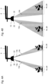
- Figure 2A shows a partial schematic view of a boom in a first tape application scattering mode according to an embodiment of the invention.
- a belt application or a belt application gritting operation is understood here as a row-related application of grit along application strips, in contrast to the full-surface application of grit.
- the AusbringstMail can along rows of plants R or z. B. for weed control, also run between rows of plants, i.e. along intermediate areas Z.
- Figure 2A illustrates a band application where the spreading strips run along rows of plants R.
- the distribution devices 10 of the fertilizer spreader 1 can be configured for the implementation of this first belt application spreading operation in such a way that each distribution device 10 spreads two adjacent spreading fans 12, here the spreading fans 12a and 12b, with different spreading directions 13a, 13b and different non-overlapping impact areas 14 of the spreading material can generate.
- Spreading material is applied to adjacent rows of plants R by means of the spreading fans 12a and 12b, leaving out the intermediate area Z of the rows of plants.
- the individual distribution devices are, for example, 1.5 meters apart along the linkage, this still makes it possible to apply a band to plant row structures whose row spacing is smaller than the spacing of the distribution devices 10 from one another.
- FIG 2A is also shown that the distribution devices 10 are each connected to only one of the distribution lines 4 for supplying grit. How the grit flow conveyed via the associated distribution line 4 and arriving at a distribution device 10 is divided up to produce the multiple grit compartments 12a, 12b is explained below with reference to FIG Figures 6 to 9 explained as an example.
- Figure 2B shows a partial schematic view of a boom in a second tape application spreading mode according to an embodiment of the invention.
- the distribution devices 10 of the fertilizer spreader 1 again produce two adjacent spreading fans 12a and 12b with different ones for carrying out this second band application spreading operation in the spreading operation Spreading directions 13a, 13b and different non-overlapping impact areas 14 of the spreading material, with the spreading material now being applied to adjacent intermediate areas Z of plant rows by means of the spreading fans 12a, 12b, leaving out the plant rows R.
- This can be done, for example, by the same configuration of the distribution devices 10 as in the first belt application -Scattering operation can be achieved, but in contrast to this, the distribution linkage is positioned offset transversely to the rows of plants R by half a row spacing.
- the jet directions 13a, 13b of the scattering fans can also be changed by changing a pivoting position of the baffle plates used to generate the scattering fans.
- the baffle plates can be pivotably arranged on the distribution linkage.
- a particular advantage of the fertilizer spreader 1 is, however, that the distribution devices 10 are each designed to produce a variable number of spread compartments 12a, 12b, 12c, ie the number of simultaneously generated spread compartments that is produced by each distribution device 10 in spreading operation can be adjusted .
- This is exemplified by the Figure 3A 11 showing a partial schematic view of a boom in a third tape application scattering mode.
- the distribution devices 3 can also be configured in such a way that they each produce three different spreading fans 12a, 12b, 12c with different spreading directions and different non-overlapping impact areas 14 of the spreading material during spreading operation.
- This is e.g. B. advantageous for a band application for row spacing of the rows of plants R, which are smaller than the row spacing as in the Figures 2A and 2B shown.
- the scatter fans produced are directed towards the rows of plants R, leaving out the intermediate areas.
- the Figure 3B a fourth belt application scattering operation, which differs from the third belt application scattering operation only in that the spread fan generated is directed towards the intermediate areas Z, leaving out the rows of plants R (similar to the second belt application scattering operation of Figure 2B ).
- the distribution devices 10 can be used to generate the spread fan in the Figures 2A to 3B for example according to the embodiment of FIG figure 7 be carried out, which will be described below. By means of this embodiment, for example, one, two or three spreading compartments can be generated per distribution device 10.
- Figure 4A first shows a schematic partial view of a boom in the first band application spreading operation, as already shown in Figure 2A described.
- Figure 4B shows Figure 4B a fifth tape application spread operation, which differs from that in Figure 4A differs in that the spreading fan 12a, 12b and thus the spreading width 24 generated are widened.
- the scattered fans are directed towards the rows of plants R.
- FIGS 5A and 5B show to the Figures 4A and 4B corresponding litter farms with the difference that the litter fans are now directed towards the intermediate areas Z between the rows of plants. Another difference is that the initial areas 22 of the different spread fans 12a, 12b in the Figures 5A and 5B overlap because they are generated by different impact surfaces of the same baffle plate, while the scatter fans 12a, 12b in the Figures 4A and 4B are generated by different impact plates (cf. figure 6 ).
- FIG 6 shows a highly schematic representation of a distribution device 10 according to an embodiment of the invention.
- the distribution devices 10 have two baffle plates 11a, 11b which are arranged adjacent to one another and which each form different dispensing areas for generating different spreading fans.
- the baffle plates 11a, 11b are attached to the distribution linkage 2 with different orientations.
- deployment areas are here the deployment areas 16a and 16b for generating the scattered fans 12a, 12b (the latter are not shown).
- the discharge areas 16a and 16b are formed by the impact surfaces of the impact plates.
- the distribution devices 10 also each have a configurable and/or controllable dividing device 15 .
- the dividing device 15 is designed to generate a variable number of grit partial flows 18, here the partial flows 18a and 18b, from the grit flow 17 arriving at the respective distribution device via the associated distribution line 4.
- the dividing device 15 can be used to change which of the dispensing areas 16a, 16b the grit arriving at on the input side of the respective distribution device 10 is conveyed to.
- the dividing device 15 has its own feed section 19a, 19b, preferably its own feed pipe, for each of the discharge areas.
- a switch, flap and/or an opening/closing mechanism 20 is arranged on the inlet side of the feed sections 19a, 19b, with which it is possible to adjust and/or change which of the feed section(s) 19a, 19b the grit arriving at the respective distribution device 10 on the inlet side is conveyed to becomes.
- actuatable (pivotable) flaps 20 are shown, which can be brought into an open position in which the grit arriving at the flap can reach the subsequent feed section 19a or 19b and which can be brought into a closed position in which the grit arriving at the flap cannot get into the subsequent feed section 19a or 19b.
- a flap 20 is arranged on the input side of each of the feed sections 19a, 19b. The flaps 20 can be actuated independently of one another.
- no spread fan both flaps in the closed position
- one spread fan only one flap open
- two spread fans both flaps open
- both flaps of each distribution device 10 are open, the flow of grit arriving on the input side of the respective distribution device 10 is divided into two partial flows 18a, 18b of grit, which are each conveyed by means of the air volume flow along one of the feed sections 19a, 19b onto the baffle plates 11a, 11b and there under Formation of the two spread fans 12a, 12b bounce off. If only one of the flaps is open, the jet direction of the spread fan generated can also be adjusted by selecting which of the two flaps is opened.
- the dividing device 15 is manually configurable, e.g. B. by the flaps can be brought manually by a user either in the open position or the closed position.
- the flaps can have a corresponding actuating element, e.g. B. have an adjusting lever to change the flap position.
- a lock can be provided in order to be able to lock the flaps and/or the operating lever in the respective position.
- the dividing device it is possible for the dividing device to be controllable in order to change its configuration.
- the flaps can be brought into the open position or the closed position by means of a controllable actuator.
- the actuators for each flap can do this z. B. have an electrically, hydraulically or pneumatically actuated actuating cylinder, which is controlled by a control device 5 (cf. also figure 10 ) can be controlled.
- the operation of the control device can e.g. B. by a user via an operator terminal 6 (see also figure 10 ) being controlled.
- the embodiment shown can thus optionally one or two spread fans 12 are generated simultaneously.
- baffle plates it is also possible for the baffle plates to have an associated actuator, by means of which the shape of the baffle plate, in particular the shape of the baffle surface, can be changed in order in this way to change the width of the impact area of the spreading fan of the baffle plate.
- the baffle plates or at least a part of them could be pivotably arranged on the distribution linkage 2 by means of a pivoting device in order to change the position of the impact area 14 of the respective baffle plate.
- an alternative embodiment provides for the different application areas (the different baffle surfaces) to be formed by a single baffle plate, which has impingement surfaces arranged at an angle to one another to form the different Has deployment areas.
- the baffle plate is also possible for the baffle plate to be designed as a multi-part baffle plate, with the individual sections of the baffle plate being designed to be adjustable relative to one another in order to form the different dispensing areas. This allows z. B. those in the Figures 5a and 5B scatter images shown are generated. It is advantageous here to separate the different impact surfaces by means of a guide web, so that the spreading material can be better guided within one impact surface by means of the guide web.
- figure 7 shows another embodiment, by means of which one, two or three spread fans 12 can be generated simultaneously.
- This embodiment differs from that in figure 6 shown only in that three baffle plates 11a, 11b, 11c are provided per distribution device 10, which form three different dispensing areas (impact surfaces) 16a, 16b, 16c, that three feed sections 19a, 19b, 19c and three flaps 20 are provided. Otherwise, the above applies to the embodiment of figure 6 Said analogously also for the embodiment of figure 7 .
- FIG figure 8 shows a highly schematic representation of a further embodiment of a distribution device 10, which is a modification of the embodiment of FIG figure 6 represents.
- one or two spread fans 12 can be generated at the same time.
- This embodiment differs from the embodiment of FIG figure 6 essentially only through the design of the dividing device 15, in particular the opening-closing mechanism 20.
- the opening-closing mechanism is formed here by an adjustable switch 20, the fixed end of which is pivotably arranged at the fork point of the two feed sections 19a, 19b and the free end of which in figure 8 from left to right and vice versa is pivotable.
- the diverter 20 can thus be brought into a first end position in which the feed path 19a is closed, into a middle position in which the two feed paths 19a, 19b are open and into an end position in which the feed path 19b is closed.
- two spread fans switch in the middle position
- just one spread fan switch in the first or second end position
- its direction and area of impact can be optionally changed, depending on whether the flap is brought into the first or second end position.
- figure 9 shows a highly schematized representation of a further embodiment, by means of which one, two, three, four or five spreading fans 12 can be generated at the same time.
- This embodiment differs from that in figure 6 shown only in that five impact plates 11a, 11b, 11c, 11d, 11e are provided per distribution device 10 (instead of two), which form five different discharge areas (impact surfaces) 16a, 16b, 16c, 16d, 16e, that the distribution line 4 branches into five separate supply routes 19a, 19b, 19c, 19d, 19e and that the dividing device 15 comprises five flaps (not shown), which are arranged on the input side of the supply routes 19a, 19b, 19c, 19d, 19e.
- the above applies to the embodiment of figure 6 Said analogously also for the embodiment of figure 9 .
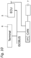
- FIG. 12 shows a schematic block diagram of a communication system of the fertilizer spreader 1.
- FIG Figure 1A The communication system can have a data bus in a manner known per se, e.g. B. a CAN data bus and/or a data bus designed as an ISOBUS. Instead of a data bus, the components can communicate with one another via an Ethernet data network.
- a control device 5, e.g. B. a control unit, an operator terminal 6 (referred to as a terminal in Figure 1C, e.g. an ISOBUS terminal) and a detection device 7 for detecting rows of plants or a grid of rows of plants are in signal connection with the communication system via corresponding data interfaces.
- the operator terminal can also be an operator terminal of the tractor if it is z.
- the fertilizer spreader is a towed fertilizer spreader.
- control device 5 can be set up to change the spreading pattern, preferably for carrying out a belt application, to control the dividing device 15 in order to reduce the number of spreading material - to change sub-streams.
- the control device 5 can have a signal connection with the operating terminal 6 and be set up to generate a control signal depending on information about row spacing entered or stored via the operating terminal 6, preferably for carrying out a belt application and for controlling the dividing device.
- control device 5 can have a signal connection with a detection device 7 for detecting a row of plants or a grid of rows of plants formed by rows of plants.
- the detection device 7 can comprise, for example, a camera (not shown) arranged on the distribution linkage. A position of the distribution devices 10 relative to a row of plants or a grid of rows of plants can also be determined by means of the camera.
- the control device 5 can be set up to generate its control signals as a function of the data recorded by the detection device 7, preferably to carry out a tape application and/or to control the dividing device 15.
- the control device 5 can be set up using the camera data to determine a row spacing or a spacing of a plant row grid and, depending on this, to optionally set either two or three simultaneously generated spreading fans per distribution device 10 by the control device 5 expediently controlling the dividing device 15 for this purpose.
- the first or second band application spreading operation can be set (cf. Figures 2A and 2B ) and with smaller row spacings the third or fourth band application spreading operation (cf. Figures 3A and 3B ) can be set.
- control device 5 it is also possible for the control device 5 to be set up to generate control signals for changing a width and/or position of the impact areas 14 as a function of information on row spacing entered or stored via the operating terminal 6 and as a function of the data recorded by the recording device 7 .
- the baffle plates have an actuator for changing the shape of the baffle surfaces and have a pivoting device to change the pivoted position of the baffle plate relative to the distribution linkage.
- control device 5 it is also possible for the control device 5 to be set up to control the dosing device 8 for dosing the grit into the distribution lines 4 in such a way that the dosing of the grit can be adapted as a function of the variable number of litter compartments.
- each distribution line 4 can be assigned a separate dosing device for grit, so that depending the number of spreading compartments and/or depending on the width of the spreading compartments, the quantity of distribution material metered by means of the metering devices can optionally be adjusted manually (e.g. via the operating terminal 6) and/or automatically.
Abstract
Es wird ein pneumatischer Düngerstreuer zur Verteilung von granularem Streugut offenbart. Der pneumatische Düngerstreuer (1) weist ein Verteilgestänge (2) zum Ausbringen von körnigem Streugut auf, umfassend zwei seitliche Ausleger (3), die jeweils eine Mehrzahl von Verteilleitungen (4) und Verteilvorrichtungen (10) zum Ausbringen des Streuguts aufweisen. Hierbei ist das Streugut entlang der Verteilleitungen (4), die zumindest abschnittsweise am Verteilgestänge (2) angeordnet sind, mittels eines Luftvolumenstroms in Richtung der Verteilvorrichtungen (10) förderbar. Die Verteilvorrichtungen (10) zum Ausbringen des Streuguts umfassen jeweils mindestens ein Ausbringelement (11), vorzugsweise einen Prallteller oder ein Leitelement, zur Ausbildung eines Streufächers (12) aus körnigem Streugut. Der pneumatische Düngerstreuer zeichnet sich dadurch aus, dass die Verteilvorrichtungen (10) jeweils zur Erzeugung einer veränderlichen Anzahl von Streufächern (12a, 12b) ausgebildet sind.A pneumatic fertilizer spreader for distributing granular spreading material is disclosed. The pneumatic fertilizer spreader (1) has a distribution linkage (2) for spreading granular spreading material, comprising two lateral booms (3) each having a plurality of distribution lines (4) and distribution devices (10) for spreading the spreading material. The grit can be conveyed along the distribution lines (4), which are arranged at least in sections on the distribution linkage (2), by means of an air volume flow in the direction of the distribution devices (10). The distribution devices (10) for spreading the grit each comprise at least one spreading element (11), preferably a baffle plate or a guide element, for forming a spreading fan (12) of granular grit. The pneumatic fertilizer spreader is characterized in that the distribution devices (10) are each designed to produce a variable number of spread compartments (12a, 12b).
Description
Die Erfindung betrifft einen pneumatischen Düngerstreuer zur Verteilung von granularem Streugut.The invention relates to a pneumatic fertilizer spreader for distributing granular spreading material.
Aus dem Stand der Technik sind pneumatische Düngerstreuer bekannt. Düngerstreuer dienen zur Verteilung von granularem (körnigem) Streugut (Dünger, Saatgut und/oder dergl.). Zum Ausbringen des körnigen Streuguts weisen derartige Düngerstreuer ein Verteilgestänge hoher Arbeitsbreite mit daran angeordneten Verteileinrichtungen bzw. Ausbringelementen (z. B. Pralltellern) auf. Das Verteilgestänge umfasst zwei seitliche Ausleger, die jeweils eine Mehrzahl von Verteilleitungen und Ausbringelementen zum Ausbringen des Materials aufweisen. Hierbei wird das Streugut entlang der Verteilleitungen, die zumindest abschnittsweise am Verteilgestänge angeordnet sind, mittels eines Luftvolumenstroms in Richtung der Ausbringelemente gefördert. Die Ausbringelemente weisen zum Ausbringen des Streuguts jeweils einen Prallteller zur Ausbildung eines Streufächers aus Streugut auf. Ein derartiger pneumatischer Düngerstreuer ist beispielsweise in der
Pneumatische Düngerstreuer bieten gegenüber sog. Scheibenstreuern bzw. Zentrifugalstreuern, bei welchen die Verteilung des Streuguts mittels eines scheibenförmigen Schleuderwerks erfolgt, den Vorteil, dass teilflächenspezifische Anwendungen (z. B. Section-Control-Anwendungen) einfacher möglich sind und bei starken Winden ein besseres Streubild (Wurfbild) erzeugbar ist.Pneumatic fertilizer spreaders offer the advantage over so-called disc spreaders or centrifugal spreaders, in which the spreading material is distributed by means of a disc-shaped centrifugal mechanism, that site-specific applications (e.g. section control applications) are easier to implement and a better spreading pattern in strong winds (Throw image) can be generated.
Bei der Ausbringung von Streugut auf eine landwirtschaftliche Nutzfläche kann es je nach Ausbringvorgang von Vorteil sein, wenn das Streugut in die unmittelbare Umgebung der jeweiligen Pflanzen auf der landwirtschaftlichen Nutzfläche abgegeben wird. Da die Aussaat einer Vielzahl von landwirtschaftlichen Nutzpflanzen entlang von Saatreihen erfolgt, bilden sich auf der landwirtschaftlichen Nutzfläche während der Wachstumsphase der Nutzpflanzen Pflanzenreihen aus. Für eine besonders effektive und wirksame Ausbringung von Streugut wäre daher die Möglichkeit einer reihenbezogenen Streugutausbringung wünschenswert, so dass das Streugut im Wesentlichen entlang von Ausbringstreifen ausgebracht wird. Die Ausbringstreifen können entlang von Pflanzenreihen oder, z. B. zur Unkrautbekämpfung, auch zwischen Pflanzenreihen verlaufen. Eine reihenbezogene Ausbringung entlang von Ausbringstreifen kann auch als Bandapplikation bezeichnet werden im Unterschied zur ganzflächigen Applikation von Streugut.When applying grit to an agricultural area, it can be advantageous, depending on the application process, if the grit is released into the immediate vicinity of the respective plants on the agricultural area. Since a large number of agricultural crops are sown along seed rows, rows of plants form on the agricultural land during the growth phase of the crops. For a particularly effective application of grit, the possibility of a row-related application of grit would therefore be desirable, so that the grit is applied essentially along application strips. The application strips can be placed along rows of plants or, e.g. B. for weed control, also run between rows of plants. A row-related application along application strips can also be referred to as a band application in contrast to the full-surface application of grit.
Bei aus der Praxis bekannten pneumatischen Düngerstreuern sind die am Verteilgestänge angeordneten Ausbringelemente, die jeweils über eine separate Verteilleitung (Förderleitung) mit Streugut versorgt werden, typischerweise im Abstand von 1,5 Metern angeordnet - in Längserstreckungsrichtung des Verteilgestänges gesehen. Der Grund ist, dass die Vielzahl entlang des Verteilgestänges verlaufender Förderleitungen viel Bauraum benötigen und entsprechend schwer sind. Mit einem derartigen Aufbau ist jedoch eine Bandapplikation bei Reihenkulturen, die in der Regel einen der üblichen Reihenabstände von 25cm, 50 cm oder 75 cm aufweisen, nicht möglich.In the case of pneumatic fertilizer spreaders known from practice, the dispensing elements arranged on the distribution linkage, which are each supplied with spreading material via a separate distribution line (conveying line), are typically arranged at a distance of 1.5 meters - in Seen longitudinal direction of the distribution linkage. The reason is that the large number of delivery lines running along the distribution rods require a lot of space and are correspondingly heavy. With such a structure, however, a band application in row cultures, which usually have one of the usual row spacings of 25 cm, 50 cm or 75 cm, is not possible.
Es ist somit eine Aufgabe der Erfindung, eine verbesserte Technik für pneumatische Düngerstreuer bereitzustellen, mit der Nachteile herkömmlicher Techniken vermieden werden können. Es ist insbesondere eine Aufgabe der Erfindung, einen pneumatischen Düngerstreuer bereitzustellen, mit dem eine verbesserte pflanzenreihenbezogene Ausbringung von granularem Streugut realisiert werden kann.It is therefore an object of the invention to provide an improved technique for pneumatic fertilizer spreaders, with which the disadvantages of conventional techniques can be avoided. It is in particular an object of the invention to provide a pneumatic fertilizer spreader with which an improved application of granular spreading material in relation to the plant rows can be implemented.
Diese Aufgabe wird durch einen pneumatischen Düngerstreuer mit den Merkmalen des unabhängigen Anspruchs gelöst. Vorteilhafte Weiterbildungen sind in den abhängigen Ansprüchen und der Beschreibung angegeben.This object is solved by a pneumatic fertilizer spreader with the features of the independent claim. Advantageous developments are specified in the dependent claims and the description.
Gemäß einem allgemeinen Gesichtspunkt der Erfindung wird ein pneumatischer Düngerstreuer bereitgestellt, der in an sich bekannter Weise ein Verteilgestänge zum Ausbringen von körnigem Streugut (Material), wie Dünger, Saatgut und/oder dergl., aufweist. Der Düngerstreuer kann somit nicht nur zur Ausbringung von Dünger auf eine landwirtschaftliche Fläche, sondern auch von anderem körnigen Material genutzt werden. Das Verteilgestänge umfasst zwei seitliche Ausleger, die jeweils eine Mehrzahl von Verteilleitungen, vorzugsweise Schlauchleitungen, und Verteilvorrichtungen zum Ausbringen des Streuguts (Materials) aufweisen. Hierbei ist das Streugut entlang der Verteilleitungen, die zumindest abschnittsweise am Verteilgestänge angeordnet sind, mittels eines Luftvolumenstroms in Richtung der Verteilvorrichtungen förderbar. Das Verteilgestänge erstreckt sich (in Arbeitsstellung) quer zu einer Fahrtrichtung des Düngerstreuers.According to a general aspect of the invention, a pneumatic fertilizer spreader is provided which, in a manner known per se, has a distribution linkage for spreading granular spreading material (material), such as fertilizer, seed and/or the like. The fertilizer spreader can thus be used not only for spreading fertilizer on an agricultural area, but also for other granular material. The distribution linkage comprises two lateral booms, each of which has a plurality of distribution lines, preferably hose lines, and distribution devices for discharging the grit (material). In this case, the grit can be conveyed along the distribution lines, which are arranged at least in sections on the distribution linkage, by means of an air volume flow in the direction of the distribution devices. The distribution linkage extends (in the working position) transversely to a direction of travel of the fertilizer spreader.
Die Verteilvorrichtungen weisen zum Ausbringen des Streuguts jeweils mindestens ein Ausbringelement zur Ausbildung eines Streufächers aus Streugut auf. Das Ausbringelement kann als Prallelement, z. B. als Prallteller, ausgeführt sein. Das Ausbringelement kann auch als ein Leitelement ausgeführt sein, das vorzugsweise einen gekrümmten Verlauf aufweist, so dass das auf das Leitelement pneumatisch geförderte Streugut durch den gekrümmten Verlauf entsprechend unter Ausbildung eines Streufächers ausgebracht wird.For spreading the spreading material, the distribution devices each have at least one spreading element for forming a spreading fan of spreading material. The dispensing element can be used as an impact element, e.g. B. be executed as a baffle plate. The dispensing element can also be designed as a guide element, which preferably has a curved course, so that the material to be spread pneumatically conveyed onto the guide element is discharged through the curved course, forming a spreading fan.
Der pneumatischer Düngerstreuer zeichnet sich dadurch aus, dass die Verteilvorrichtungen jeweils zur Erzeugung einer veränderlichen Anzahl von Streufächern ausgebildet sind. Mit einer Verteilvorrichtung kann somit nicht nur genau ein Streufächer aus Streugut erzeugt werden, sondern eine anpassbare Anzahl von gleichzeitig durch eine Verteilvorrichtung erzeugten Streufächern. Dies bietet den Vorteil, dass das Streumuster des auszubringenden Verteilguts flexibler angepasst werden kann, insbesondere besser an eine reihenbezogene Ausbringung angepasst werden kann. Somit ist es möglich, dass gezielt Pflanzenreihen behandelt, z. B. gedüngt werden, oder alternativ gezielt Zwischenbereiche von Pflanzenreihen behandelt, z. B. gedüngt, werden.The pneumatic fertilizer spreader is characterized in that the distribution devices are each designed to produce a variable number of spreading fans. With a distribution device, it is not only possible to produce exactly one scatter fan from grit, but also an adjustable number of scatter fans created simultaneously by a distribution device. This offers the advantage that the scattering pattern of the material to be distributed can be adjusted more flexibly, in particular it can be better adapted to a row-related application. It is thus possible that plant rows are treated in a targeted manner, e.g. B. be fertilized, or alternatively specifically treated intermediate areas of plant rows, z. B. are fertilized.
Beispielsweise kann die wahlweise veränderliche Anzahl von Streufächern kleiner gleich 5 sein. In einer besonders bevorzugten Ausführungsform können die Verteilvorrichtungen jeweils zur wahlweisen Erzeugung von einem Streufächer und/oder von zwei Streufächern ausgebildet sein. Alternativ oder zusätzlich können die Verteilvorrichtungen jeweils zur wahlweisen Erzeugung von einem Streufächer, von zwei Streufächern und/oder von drei Streufächern ausgebildet sind. Diese veränderliche Anzahl von Streufächern ermöglicht einerseits ein ausreichend flexibles Anpassen des Streubildes für die üblichsten Pflanzenreihenmuster und ist andererseits hinsichtlich benötigtem Bauraum und Kostenaufwand vorteilhaft realisierbar.For example, the optionally variable number of scattering compartments can be less than or equal to 5. In a particularly preferred embodiment, the distribution devices can each be designed for the selective generation of one spread fan and/or two spread fans. As an alternative or in addition, the distribution devices can each be designed for the selective generation of one spread fan, two spread fans and/or three spread fans. On the one hand, this variable number of spreading fans enables a sufficiently flexible adaptation of the spreading pattern for the most common plant row patterns and, on the other hand, it can be implemented advantageously with regard to the required installation space and costs.
Der Begriff "wahlweise" bedeutet, dass die Anzahl der Streufächer, die beim Ausbringvorgang jeweils durch eine bestimmte Verteilvorrichtung erzeugt werden, ausgewählt werden kann, z. B. eingestellt werden kann. Das Auswählen oder Einstellen der Anzahl an Streufächern kann durch eine entsprechende Konfiguration, z. B. eine manuelle Konfiguration und/oder eine automatisierte Ansteuerung der Verteilvorrichtungen erfolgen, was nachfolgend noch erläutert wird.The term "optional" means that the number of spreading fans that are generated by a specific distribution device during the spreading process can be selected, e.g. B. can be adjusted. The selection or adjustment of the number of spreading compartments can be carried out by an appropriate configuration, e.g. B. a manual configuration and / or automated control of the distribution devices, which will be explained below.
In diesem Dokument werden die Begriffe "Streufächer", "Streurichtung" und "Auftreffbereich" verwendet, die nachfolgend kurz erläutert werden.In this document, the terms "scattering fan", "scattering direction" and "impact area" are used, which are briefly explained below.
Unter Streufächer wird ein fächerförmiges Streubild verstanden, das sich ergeben kann, wenn Streugut von einem Prallteller oder einem Leitelement abprallt und sich anschließend auf dem Weg zur landwirtschaftlichen Fläche fächerartig aufweitet. Bei dem Streufächer handelt es sich um einen dreidimensionalen Streufächer. Die dreidimensionale Ausdehnung des Streufächers setzt sich durch die flächige Ausdehnung des Streufächers und die im Streufächer enthaltene Düngermenge zusammen. Unter Streurichtung kann die in dem Streufächer liegende gemittelte Streurichtung des Streuguts eines Streufächers verstanden werden. Unter benachbarten Streufächern werden Streufächer verstanden, die in Längserstreckungsrichtung des Verteilgestänges nebeneinander /aufeinander folgend angeordnet sind. Der Auftreffbereich ist der Auftreffbereich des Streuguts auf der zu behandelnden landwirtschaftlichen Fläche.Scatter fans are understood to mean a fan-shaped scatter pattern that can result when grit bounces off a baffle plate or a guide element and then spreads out like a fan on the way to the agricultural area. The spread fan is a three-dimensional spread fan. The three-dimensional expansion of the spreading fan is made up of the two-dimensional expansion of the spreading fan and the amount of fertilizer contained in the spreading fan. Scattering direction can be understood as meaning the mean scattering direction of the scattering material of a scattering fan lying in the scattering fan. Adjacent spreading fans are understood to mean spreading fans which are arranged next to one another/following one another in the direction of the longitudinal extent of the distribution linkage. The impact area is the impact area of the spreading material on the agricultural area to be treated.
In einer weiteren Ausführungsform sind die Verteilvorrichtungen jeweils ausgebildet, wahlweise benachbarte Streufächer mit unterschiedlichen Streurichtungen und/oder mit unterschiedlichen Auftreffbereichen, weiter vorzugsweise mit überlappfreien Auftreffbereichen, des Streuguts zu erzeugen. Dies ist besonders vorteilhaft für die Bandapplikation des Streuguts, da hierdurch Streugut durch die Verteilvorrichtungen jeweils auf benachbarte Pflanzenreihen ausgebracht werden kann, insbesondere auch mit pneumatischen Düngerstreuern, deren Verteilvorrichtungen herkömmlich beabstandet angeordnet sind, z. B. im Abstand von ca. 1, 5 Metern.In a further embodiment, the distribution devices are each designed to selectively supply adjacent spreading fans with different spreading directions and/or with different impact areas, more preferably with overlap-free impact areas, of the material to be spread generate. This is particularly advantageous for the band application of the grit, since this grit can be applied through the distribution devices in each case on adjacent rows of plants, in particular with pneumatic fertilizer spreaders whose distribution devices are conventionally spaced, z. B. at a distance of about 1.5 meters.
In einer weiteren Ausführungsform weisen die Verteilvorrichtungen jeweils eine konfigurierbare und/oder ansteuerbare Aufteilvorrichtung auf, die zur Erzeugung einer veränderlichen Anzahl von Streugut-Teilströmen aus dem an der jeweiligen Verteilvorrichtung ankommenden Streugutstrom ausgebildet ist. Hiermit kann die veränderliche Anzahl von Streufächern an einer Verteilvorrichtung besonders vorteilhaft realisiert werden.In a further embodiment, the distribution devices each have a configurable and/or controllable dividing device which is designed to generate a variable number of grit partial flows from the grit flow arriving at the respective distribution device. In this way, the variable number of spreading compartments on a distribution device can be realized in a particularly advantageous manner.
Gemäß einer bevorzugten Ausführungsvariante dieser Ausführungsform weisen die Verteilvorrichtungen jeweils unterschiedliche Ausbringbereiche, vorzugsweise unterschiedliche Prallflächen, zur Erzeugung unterschiedlicher Streufächer auf, wobei mittels der Aufteilvorrichtung veränderbar ist, zu welchen der Ausbringbereiche das eingangsseitig an der jeweiligen Verteilvorrichtung ankommende Streugut gefördert wird. Vorteilhaft wird eine kompakte Realisierung ermöglicht, um die veränderliche Anzahl von Streufächern zu erzeugen.According to a preferred variant of this embodiment, the distribution devices each have different application areas, preferably different impact surfaces, for generating different spreading fans, it being possible to change by means of the distribution device to which of the application areas the material arriving on the input side of the respective distribution device is conveyed. A compact implementation is advantageously made possible in order to generate the variable number of spread fans.
Hierbei kann die Aufteilvorrichtung für jeden der Ausbringbereiche eine eigene Zufuhrstrecke, vorzugsweise ein eigenes Zufuhrrohr, aufweisen. Ferner kann eingangsseitig der Zufuhrstrecke(n) eine Weiche, Klappen und/oder ein Öffnungs-Schließmechanismus angeordnet sein, womit einstellbar und/oder veränderbar ist, in welche der Zufuhrstrecke(n) das eingangsseitig an der jeweiligen Verteilvorrichtung ankommende Streugut gefördert wird. Entsprechend kann hierdurch eine flexible Steuerung und/oder Aufteilung des Streuguts zur Erzeugung der unterschiedlichen Streufächer realisiert werden.In this case, the dividing device can have its own feed path, preferably its own feed pipe, for each of the dispensing areas. Furthermore, a switch, flaps and/or an opening/closing mechanism can be arranged on the input side of the feed section(s), with which it is possible to adjust and/or change which of the feed section(s) the grit arriving at the respective distribution device on the input side is conveyed to. Accordingly, a flexible control and/or division of the spreading material can be realized in this way to generate the different spreading fans.
In einer Ausführungsform sind die unterschiedlichen Ausbringbereiche einer Verteilvorrichtung durch unterschiedliche Ausbringelemente, vorzugsweise durch unterschiedliche Prallteller oder Leitelemente, ausgebildet, die benachbarte Streufächer mit unterschiedlicher Streurichtung erzeugen und vorzugsweise unterschiedlich orientiert am Verteilgestänge befestigt sind. Jede der Verteilvorrichtungen kann somit mehrere Prallteller oder Leitelemente aufweisen, die z. B. unterschiedlich ausgerichtet (orientiert) und/oder unterschiedlich ausrichtbar am Verteilgestänge angeordnet sind.In one embodiment, the different dispensing areas of a distribution device are formed by different dispensing elements, preferably by different baffle plates or guide elements, which produce adjacent spreading fans with different spreading directions and are preferably attached to the distribution linkage with different orientations. Each of the distribution devices can thus have several baffle plates or guide elements z. B. differently aligned (oriented) and / or arranged differently aligned on the distribution linkage.
In einer hierzu alternativen Ausführungsform sind die unterschiedlichen Ausbringbereiche einer Verteilvorrichtung jeweils durch ein einziges Ausbringelement ausgebildet, welches winkelig zueinander angeordnete Auftreffflächen zur Ausbildung der unterschiedlichen Ausbringbereiche aufweist. Alternativ oder zusätzlich sind die unterschiedlichen Ausbringbereiche einer Verteilvorrichtung jeweils durch einen einzigen mehrteilig ausgeführten Prallteller ausgebildet, wobei die einzelnen Abschnitte des Pralltellers zur Ausbildung der unterschiedlichen Ausbringbereiche zueinander verstellbar ausgeführt sind. Die unterschiedlichen Ausbringbereiche können manuell zueinander verstellbar sein oder eine ansteuerbare Aktorik aufweisen und mittels der Aktorik automatisiert zueinander verstellbar sein.In an alternative embodiment to this, the different dispensing areas of a distribution device are each formed by a single dispensing element, which has impingement surfaces arranged at an angle to one another to form the different dispensing areas having. Alternatively or additionally, the different dispensing areas of a distribution device are each formed by a single multi-part baffle plate, with the individual sections of the baffle plate being designed to be adjustable relative to one another in order to form the different dispensing areas. The different application areas can be manually adjustable relative to one another or can have a controllable actuator system and be automatically adjustable relative to one another by means of the actuator system.
Gemäß einer Ausführungsvariante hiervon kann das Ausbringelement mindestens einen Leitsteg zur Trennung der unterschiedlichen Ausbringbereiche und zur Führung des Streuguts innerhalb eines Auftreffbereichs aufweisen. Hierdurch kann auf konstruktiv kosteneffiziente Weise eine zuverlässige Aufteilung und Führung des Streuguts mittels lediglich eines Ausbringelements zur Erzeugung unterschiedlicher Streufächer realisiert werden.According to an embodiment variant of this, the dispensing element can have at least one guide web for separating the different dispensing areas and for guiding the grit within an impact area. In this way, a reliable distribution and guidance of the spreading material can be realized in a structurally cost-efficient manner by means of only one dispensing element for generating different spreading fans.
In einer weiteren bevorzugten Ausführungsform umfasst der pneumatische Düngerstreuer eine Steuerungsvorrichtung, die eingerichtet ist, zur Veränderung des Streubildes, vorzugsweise zur Durchführung einer Bandapplikation, die Aufteilvorrichtung anzusteuern, um die Anzahl von Streugut-Teilströmen zu verändern. In einer Ausführungsvariante hiervon kann die Steuerungsvorrichtung ein Bedienterminal umfassen oder in Signalverbindung mit einem Bedienterminal stehen. Hierbei ist die Steuerungsvorrichtung eingerichtet, in Abhängigkeit von über das Bedienterminal eingegebenen oder hinterlegten Angaben zu Reihenabständen ein Steuersignal zu erzeugen, vorzugsweise zur Durchführung einer Bandapplikation und/oder zur Ansteuerung der Aufteilvorrichtung. Ein Vorteil hiervon ist, dass mittels einer Benutzereingabe die Funktion der Steuerungsvorrichtung entsprechend angepasst werden kann.In a further preferred embodiment, the pneumatic fertilizer spreader comprises a control device which is set up to change the spreading pattern, preferably to carry out a band application, to control the dividing device in order to change the number of spreading material partial flows. In an embodiment variant of this, the control device can comprise an operator terminal or have a signal connection with an operator terminal. In this case, the control device is set up to generate a control signal as a function of information about row spacings entered or stored via the operator terminal, preferably for carrying out a belt application and/or for controlling the dividing device. One advantage of this is that the function of the control device can be adjusted accordingly by means of a user input.
Alternativ oder zusätzlich kann die Steuerungsvorrichtung in Signalverbindung mit einer Erfassungseinrichtung stehen. Die Erfassungseinrichtung ist ausgebildet zur Erfassung einer Pflanzenreihe oder eines durch Pflanzenreihen gebildeten Pflanzenreihenrasters und/oder zur Erfassung einer Lage der Verteilvorrichtungen gegenüber einer Pflanzenreihe oder eines Pflanzenreihenrasters. Hierbei kann die Steuerungsvorrichtung eingerichtet sein, ihre Steuersignale in Abhängigkeit von den von der Erfassungseinrichtung erfassten Daten zu erzeugen, vorzugsweise zur Durchführung einer Bandapplikation und/oder zur Ansteuerung der Aufteilvorrichtung. Vorteilhaft können Pflanzenreihen oder ein Pflanzenreihenraster automatisch erfasst und die Steuerung des Verteilvorgangs entsprechend der Erfassung automatisiert angepasst werden. Die Erfassungseinrichtung kann eine oder mehrere Kameras umfassen, die z. B. am Verteilgestänge angeordnet sind und deren Blickwinkel auf die zu behandelnde landwirtschaftliche Fläche gerichtet ist.Alternatively or additionally, the control device can be in signal connection with a detection device. The detection device is designed to detect a row of plants or a grid of rows of plants formed by rows of plants and/or to detect a position of the distribution devices relative to a row of plants or a grid of rows of plants. In this case, the control device can be set up to generate its control signals as a function of the data recorded by the detection device, preferably for carrying out a belt application and/or for controlling the dividing device. Advantageously, rows of plants or a grid of rows of plants can be automatically recorded and the control of the distribution process can be automatically adjusted according to the recording. The detection device can comprise one or more cameras, e.g. B. are arranged on the distribution linkage and their perspective is directed to the agricultural area to be treated.
In einer weiteren Ausführungsform können die Verteilvorrichtungen zur Veränderung von Auftreffbereichen der Streufächer, vorzugsweise zur Veränderung einer Breite und/oder Lage der Auftreffbereiche, konfigurierbar und/oder ansteuerbar sein. Gemäß dieser Ausführungsform sind die Verteilvorrichtungen somit einerseits jeweils zur Erzeugung einer veränderlichen Anzahl von Streufächern ausgebildet und zusätzlich können die Auftreffbereiche der Streufächer selbst verändert werden. Im Ergebnis kann somit eine besonders flexible Anpassung des Verteilbildes der einzelnen Verteilvorrichtungen erzielt werden, insbesondere um das Verteilbild bei Bedarf an eine gewünschte Bandapplikation anpassen zu können.In a further embodiment, the distribution devices can be configurable and/or controllable for changing the impact areas of the spread fans, preferably for changing the width and/or position of the impact areas. According to this embodiment, the distribution devices are thus each designed to generate a variable number of spread fans and, in addition, the impact areas of the spread fans themselves can be changed. As a result, a particularly flexible adaptation of the distribution pattern of the individual distribution devices can be achieved, in particular in order to be able to adapt the distribution pattern to a desired belt application if necessary.
Gemäß einer weiteren Ausführungsform ist vorgesehen, dass die Steuerungsvorrichtung eingerichtet ist, in Abhängigkeit von über das Bedienterminal eingegebenen oder hinterlegten Angaben zu Reihenabständen und in Abhängigkeit von den von der Erfassungseinrichtung erfassten Daten, Steuersignale zur Veränderung einer Breite und/oder Lage der Auftreffbereiche zu erzeugen. Vorteilhaft kann eine gezielte Anpassung basierend auf den Reihenabständen eines zu behandelnden Pflanzenbestands ermöglicht werden.According to a further embodiment, the control device is set up to generate control signals for changing the width and/or position of the impact areas as a function of information on row spacing entered or stored via the operator terminal and as a function of the data recorded by the detection device. Targeted adjustment based on the row spacing of a stand of plants to be treated can advantageously be made possible.
In einer weiteren Ausführungsform kann zumindest ein Teil der Ausbringelemente jeweils mittels einer Schwenkvorrichtung verschwenkbar am Verteilgestänge angeordnet sein, zur Veränderung der Lage des Auftreffbereiches des Streufächers des Ausbringelements. Alternativ oder zusätzlich kann zumindest ein Teil der Ausbringelemente jeweils einen Prallteller oder ein Leitelement aufweisen, dessen Form mittels einer Aktorik veränderbar ist, zur Veränderung einer Breite des Auftreffbereiches des Streufächers des Ausbringelements. Mit diesen Varianten können die Streufächer, insbesondere deren Auftreffbereiche auf der landwirtschaftlichen Fläche, der entsprechenden Ausbringelemente gezielt beeinflusst werden. Hierdurch kann vorteilhaft eine Anpassung des Streubildes an beliebige Reihenabstände von Reihenkulturen ermöglicht werden.In a further embodiment, at least some of the dispensing elements can each be pivotably arranged on the distribution linkage by means of a pivoting device in order to change the position of the impact area of the spread fan of the dispensing element. Alternatively or in addition, at least some of the dispensing elements can each have a baffle plate or a guide element, the shape of which can be changed by means of an actuator, in order to change the width of the impact area of the spreading fan of the dispensing element. With these variants, the spreading fans, in particular their areas of impact on the agricultural area, of the corresponding spreading elements can be influenced in a targeted manner. As a result, an adaptation of the spread pattern to any row spacing of row crops can advantageously be made possible.
Gemäß einer weiteren Ausführungsform umfasst der pneumatischer Düngerstreuer mindestens eine Dosiervorrichtung zur Dosierung des Streuguts in die Verteilleitungen, wobei die Dosierung des Streuguts in Abhängigkeit von der veränderlichen Anzahl von Streufächern anpassbar ist, vorzugsweise automatisiert anpassbar ist. Die Effizienz der verwendeten Verteilgutmenge kann hierdurch verbessert werden. Die mindestens eine Dosiervorrichtung kann im Bereich des Vorratsbehälters für Streugut oder im Bereich des Verteilgestänges angeordnet sein.According to a further embodiment, the pneumatic fertilizer spreader comprises at least one dosing device for dosing the grit into the distribution lines, wherein the dosing of the grit can be adjusted, preferably automatically, depending on the variable number of spread compartments. The efficiency of the amount of distribution material used can be improved as a result. The at least one dosing device can be arranged in the area of the storage container for grit or in the area of the distribution linkage.
Gemäß einer weiteren bevorzugten Ausführungsform können die Verteilvorrichtungen jeweils über separate Dosiervorrichtungen mit Streugut versorgbar sein und jede der Verteilvorrichtungen kann über eine eigene Verteilleitung mit der ihr zugeordneten Dosiervorrichtung fluidisch in Verbindung stehen. Hierbei kann eine Menge an Streugut, das einer Verteilvorrichtung von der ihr zugeordneten Dosiervorrichtung zuführbar ist, manuell und/oder automatisiert anpassbar sein, vorzugsweise in Abhängigkeit einer Anzahl und/oder Breite der Streufächer der Verteilvorrichtung manuell und/oder automatisiert anpassbar sein. Mit anderen Worten kann jede Versorgungsleitung beispielsweise mit einer separaten Dosiervorrichtung mit dem jeweiligen Verteilgut versorgt werden. In Abhängigkeit der Anzahl an Streufächer und/oder in Abhängigkeit der Breite der Streufächer kann beispielsweise die Menge an mittels der Dosiervorrichtung dosiertem Verteilgut manuell und/oder automatisiert angepasst werden. Eine Verteilgutmenge kann hierdurch besonders effizient im Hinblick auf Bandapplikationsvorgänge angepasst werden.According to a further preferred embodiment, the distribution devices can each be supplied with grit via separate metering devices, and each of the distribution devices can be in fluid communication with the metering device assigned to it via its own distribution line. Here, a quantity of grit that is assigned to a distribution device by its Dosing device can be supplied, be manually and / or automatically adjustable, preferably be manually and / or automatically adjustable depending on a number and / or width of the spreading compartments of the distribution device. In other words, each supply line can be supplied with the respective material to be distributed, for example with a separate dosing device. Depending on the number of spreading compartments and/or depending on the width of the spreading compartments, the quantity of distribution material dosed by means of the dosing device can be adjusted manually and/or automatically, for example. As a result, a quantity of goods to be distributed can be adjusted in a particularly efficient manner with regard to tape application processes.
In einer weiteren Ausführungsform können die Verteilvorrichtungen zur Veränderung der Anzahl von Streufächern manuell konfigurierbar sein, z. B. manuell einstellbar und/oder manuell durch einen Benutzer umrüstbar sein. Beispielsweise ist es möglich, dass die Anzahl der Ausbringelemente, z. B. die Anzahl der Prallteller, die jeweils an den Verteilvorrichtungen montiert sind, durch einen Benutzer entsprechend korrespondierend zu der Anzahl von Streufächern pro Verteilvorrichtung manuell angepasst wird. Hierfür können vorbestimmte Montagestellen für die Prallteller pro Verteilvorrichtung vorgesehen sein. Im Rahmen der manuellen Konfiguration kann dann die Anzahl der montierten Prallteller verändert werden. Gleichzeitig kann die Aufteilvorrichtung entsprechend umkonfiguriert werden.In a further embodiment, the distribution devices can be manually configurable to change the number of spread compartments, e.g. B. manually adjustable and / or manually convertible by a user. For example, it is possible that the number of dispensing elements, e.g. B. the number of baffle plates, which are each mounted on the distribution devices, is manually adjusted by a user in accordance with the number of spreading compartments per distribution device. For this purpose, predetermined assembly points can be provided for the baffle plates per distribution device. The number of installed baffle plates can then be changed as part of the manual configuration. At the same time, the dividing device can be reconfigured accordingly.
Alternativ ist es möglich, dass das Ausbringelement durch einen Benutzer entsprechend der zur erzeugenden Anzahl von Streufächern umgebaut wird, beispielsweise durch Anpassung der jeweiligen Ausbringbereiche (Anpassung der unterschiedlichen Prallflächen). Gleichzeitig kann die Aufteilvorrichtung wieder entsprechend umkonfiguriert werden, z. B. indem der Öffnungs-Schließmechanismus, der den einzelnen Ausbringbereichen zugeordnet ist, entsprechend eingestellt wird.Alternatively, it is possible for the user to convert the dispensing element according to the number of spreading compartments to be generated, for example by adapting the respective dispensing areas (adapting the different impact surfaces). At the same time, the dividing device can be reconfigured accordingly, e.g. B. by adjusting the open-close mechanism associated with each deployment area accordingly.
Unter einer Verteilvorrichtung kann eine Baugruppe verstanden werden, die endseitig an einer Versorgungsleitung angeordnet und fluidisch angeschlossen ist und die ausgebildet ist, das eingangsseitig an der Verteilvorrichtung ankommende Streugut auf eine zu behandelnde landwirtschaftliche Fläche mittels mindestens eines Pralltellers und/oder Leitelements auszubringen. In einer weiteren Ausführungsform können die Verteilvorrichtungen jeweils lediglich nur an einer der zumindest abschnittsweise am Verteilgestänges angeordneten Verteilleitungen zur Versorgung mit Streugut angeschlossen sein.A distribution device can be understood to mean a subassembly which is arranged at the end of a supply line and is fluidically connected and which is designed to spread the grit arriving at the distribution device on the inlet side onto an agricultural area to be treated by means of at least one baffle plate and/or guide element. In a further embodiment, the distribution devices can only be connected to only one of the distribution lines, which are arranged at least in sections on the distribution linkage, for the supply of spreading material.
Alternativ oder zusätzlich können benachbarte Verteilvorrichtungen - in Längserstreckungsrichtung (L) des Verteilgestänges gesehen - einen Abstand von mindestens 1 Meter, vorzugsweise von 1,5 Meter aufweisen. Alternativ oder zusätzlich können Anfangsbereiche der unterschiedlichen Streufächer, die von der gleichen Verteilvorrichtung erzeugbar sind, - in Längserstreckungsrichtung (L) des Verteilgestänges gesehen -, einen Abstand von <_ 50 cm aufweisen. Alternativ oder zusätzlich weisen die Verteilvorrichtungen jeweils eine Längenabmessung und/oder Baugröße auf, - in Längserstreckungsrichtung (L) des Verteilgestänges gesehen -, die ≤ 50 cm beträgt.As an alternative or in addition, adjacent distribution devices—seen in the direction of longitudinal extension (L) of the distribution linkage—have a distance of at least 1 meter, preferably 1.5 meters. Alternatively or additionally, the initial areas of the different spread fans, the can be generated by the same distribution device, viewed in the longitudinal direction (L) of the distribution linkage, have a spacing of <_ 50 cm. As an alternative or in addition, the distribution devices each have a length dimension and/or structural size—seen in the direction of longitudinal extension (L) of the distribution rod—which is ≦50 cm.
In einer weiteren Ausführungsform kann das Verteilgestänge zur Einstellung seiner Höhenlage gegenüber einer zu bearbeitenden landwirtschaftlichen Fläche, insbesondere einem Pflanzenbestand, höhenverstellbar an einem Trägerfahrzeug gehaltert sein, beispielsweise mittels eines höhenverstellbaren Hubrahmens, der z. B. durch ein Parallelogrammgestänge höhenverstellbar ist.In a further embodiment, the distribution linkage can be mounted in a height-adjustable manner on a carrier vehicle for adjusting its height relative to an agricultural area to be processed, in particular a crop, for example by means of a height-adjustable lifting frame which, for. B. is adjustable in height by a parallelogram linkage.
In einer weiteren Ausführungsform kann das Verteilgestänge einen Träger und ein Mittelteil aufweisen, wobei an dem Mittelteil die zwei seitlichen Ausleger schwenkbar angebracht sind. Das Verteilgestänge kann eine hohe Arbeitsbreite aufweisen, die wesentlich größer als eine Breite eines Trägerfahrzeugs des Düngerstreuers ist, an dem das Verteilgestänge gehaltert ist. Die Arbeitsbreite kann z. B. ein Vielfaches der Breite des Trägerfahrzeugs sein. Die Arbeitsbreite des Verteilergestänges, d. h. die Breite in Arbeitsposition oder im vollständig ausgeklappten Zustand, kann mindestens 15 Meter sein, vorzugsweise mindestens 20 Meter sein. Die Ausleger können ein- und ausklappbar ausgeführt sein, so dass diese für Transportfahrten gefaltet und eingeklappt werden können.In a further embodiment, the distribution linkage can have a carrier and a central part, the two lateral booms being pivotably attached to the central part. The distribution linkage can have a large working width, which is significantly larger than a width of a carrier vehicle of the fertilizer spreader on which the distribution linkage is mounted. The working width can e.g. B. be a multiple of the width of the carrier vehicle. The working width of the distributor linkage, i. H. the width in working position or when fully unfolded, can be at least 15 meters, preferably at least 20 meters. The outriggers can be designed to fold in and out, so that they can be folded and folded in for transport.
Die zuvor beschriebenen bevorzugten Ausführungsformen und Merkmale der Erfindung sind beliebig miteinander kombinierbar. Weitere Einzelheiten und Vorteile der Erfindung werden im Folgenden unter Bezug auf die beigefügten Zeichnungen beschrieben. Es zeigen:
- Figur 1A
- eine schematische Perspektivansicht eines pneumatischen Düngerstreuers gemäß einer Ausführungsform der Erfindung;
- Figur 1B
- eine schematische Hinteransicht des Düngerstreuers aus
Figur 1A ; - Figur 2A
- eine schematische Teilansicht eines Auslegers in einem ersten Bandapplikations-Streubetrieb gemäß einer Ausführungsform der Erfindung;
- Figur 2B
- eine schematische Teilansicht eines Auslegers in einem zweiten Bandapplikations-Streubetrieb gemäß einer Ausführungsform der Erfindung;
- Figur 3A
- eine schematische Teilansicht eines Auslegers in einem dritten Bandapplikations-Streubetrieb gemäß einer Ausführungsform der Erfindung;
- Figur 3B
- eine schematische Teilansicht eines Auslegers in einem vierten Bandapplikations-Streubetrieb gemäß einer Ausführungsform der Erfindung;
- Figur 4A
- eine schematische Teilansicht eines Auslegers in dem ersten Bandapplikations-Streubetrieb gemäß einer Ausführungsform der Erfindung;
- Figur 4B
- eine schematische Teilansicht eines Auslegers in einem fünften Bandapplikations-Streubetrieb gemäß einer Ausführungsform der Erfindung;
- Figur 5A
- eine schematische Teilansicht eines Auslegers in dem zweiten Bandapplikations-Streubetrieb gemäß einer Ausführungsform der Erfindung;
- Figur 5B
- eine schematische Teilansicht eines Auslegers in einem sechsten Bandapplikations-Streubetrieb gemäß einer Ausführungsform der Erfindung;
Figur 6- eine schematische Darstellung einer Verteilvorrichtung gemäß einer Ausführungsform der Erfindung;
Figur 7- eine schematische Darstellung einer Verteilvorrichtung gemäß einer weiteren Ausführungsform der Erfindung;
- Figur 8
- eine schematische Darstellung einer Verteilvorrichtung gemäß einer weiteren Ausführungsform der Erfindung;
Figur 9- eine schematische Darstellung einer Verteilvorrichtung gemäß einer weiteren Ausführungsform der Erfindung; und
Figur 10- ein schematisches Blockdiagramm eines Kommunikationssystems des Düngerstreuers aus
Figur 1A .
- Figure 1A
- a schematic perspective view of a pneumatic fertilizer spreader according to an embodiment of the invention;
- Figure 1B
- a schematic rear view of the fertilizer spreader
Figure 1A ; - Figure 2A
- a partial schematic view of a boom in a first tape application spreading operation according to an embodiment of the invention;
- Figure 2B
- a partial schematic view of a boom in a second tape application spreading operation according to an embodiment of the invention;
- Figure 3A
- a partial schematic view of a boom in a third tape application spreading operation according to an embodiment of the invention;
- Figure 3B
- a partial schematic view of a boom in a fourth tape application spreading operation according to an embodiment of the invention;
- Figure 4A
- 12 is a partial schematic view of a boom in the first tape application scattering mode according to an embodiment of the invention;
- Figure 4B
- a schematic partial view of a boom in a fifth tape application spreading operation according to an embodiment of the invention;
- Figure 5A
- a partial schematic view of a boom in the second tape application spreading mode according to an embodiment of the invention;
- Figure 5B
- a schematic partial view of a boom in a sixth tape application spreading operation according to an embodiment of the invention;
- figure 6
- a schematic representation of a distribution device according to an embodiment of the invention;
- figure 7
- a schematic representation of a distribution device according to a further embodiment of the invention;
- figure 8
- a schematic representation of a distribution device according to a further embodiment of the invention;
- figure 9
- a schematic representation of a distribution device according to a further embodiment of the invention; and
- figure 10
- Fig. 12 shows a schematic block diagram of a communication system of the fertilizer spreader
Figure 1A .
Gleiche oder funktional äquivalente Elemente sind in den Figuren zum Teil mit denselben Bezugszeichen bezeichnet und zum Teil nicht gesondert beschrieben. Ferner sind zur besseren Übersichtlichkeit nicht immer alle gleichen Bauteile mit Bezugszeichen versehen, so dass zum Teil nur ein Teil der Verteilvorrichtungen, der Verteilleitungen, Ausbringelemente bzw. der Prallteller, etc. mit Bezugszeichen gekennzeichnet ist.Identical or functionally equivalent elements are partially denoted by the same reference symbols in the figures and partially not separately described. Furthermore, for the sake of clarity, not all of the same components are always provided with reference numbers, so that in some cases only some of the distribution devices, distribution lines, dispensing elements or baffle plates, etc. are provided with reference numbers.
Der Düngerstreuer weist ein an einem Trägerfahrzeug 9 mittelbar oder unmittelbar gehaltertes Verteilgestänge 2 zum Ausbringen von körnigem Streugut auf. Das Verteilgestänge 2 umfasst zwei seitliche Ausleger 3, die an ihrem inneren Ende schwenkbar an einem Mittelteil 3a befestigt sind und ein äußeres freies Ende aufweisen. Das Verteilgestänge 2 kann hierbei bspw. Arbeitsbreiten von mehr als 20 Metern aufweisen. Das Verteilgestänge 2 bzw. die Ausleger 3 können zumindest abschnittsweise durch eine fachwerkartige Gestängestruktur bzw. durch eine Fachwerkkonstruktion gebildet sein. Darüber hinaus weist die Gestängestruktur bzw. die Fachwerkkonstruktion eine größere Höhe als Tiefe auf.The fertilizer spreader has a
An den Auslegern 3 sind jeweils eine Mehrzahl von Verteilleitungen 4, z. B. ausgeführt als Schlauchleitungen, und Verteilvorrichtungen 10 zum Ausbringen des Streuguts angebracht. Hierbei wird das Streugut im Streubetrieb entlang der Verteilleitungen 4, die zumindest abschnittsweise am Verteilgestänge 2 angeordnet sind, mittels eines Luftvolumenstroms in Richtung der Verteilvorrichtungen 10 gefördert. Am Mittelteil 3a ist eine Dosiervorrichtung 8 angeordnet, die ausgebildet ist, das Streugut aus dem Vorratsbehälter 21 über die Dosiervorrichtung 8 in der gewünschten Menge in die einzelnen Verteilleitungen 4 zu dosieren. Der Vorratsbehälter 21, die Dosiervorrichtung 8, sowie das Streugut-Fördersystem zwischen Vorratsbehälter und Dosiervorrichtung 8 kann in an sich bekannter Weise ausgeführt sein und wird daher vorliegend nicht näher beschrieben. Lediglich beispielhaft können diese Komponenten ausgeführt sein, wie es in der Offenlegungsschrift
Die Verteilvorrichtungen 10 weisen zum Ausbringen des Streuguts jeweils mindestens ein Ausbringelement, vorzugsweise einen Prallteller oder ein Leitelement, zur Ausbildung eines Streufächers aus körnigem Streugut auf, was nachfolgend noch näher beschrieben ist. Die Verteilvorrichtungen sind vorliegend, lediglich beispielhaft, in Längserstreckungsrichtung L des Verteilgestänges gesehen, 1,5 Meter voneinander beabstandet. Die Längserstreckungsrichtung bzw. die Gestängeachse des Verteilgestänges 2 ist hier mit dem Pfeil L gekennzeichnet.For discharging the grit, the
Die Verteilvorrichtungen 10 des Düngerstreuers 1 weisen die Besonderheit auf, dass sie jeweils zur Erzeugung einer veränderlichen Anzahl von Streufächern ausgebildet sind, was anhand der nachfolgenden Figuren beschrieben wird.The
Die Verteilvorrichtungen 10 des Düngerstreuers 1 können für die Durchführung dieses ersten Bandapplikations-Streubetriebs so konfiguriert werden, dass jede Verteilvorrichtung 10 im Streubetrieb zwei benachbarte Streufächer 12, hier die Streufächer 12a und 12b, mit unterschiedlichen Streurichtungen 13a, 13b und unterschiedlichen überlappfreien Auftreffbereichen 14 des Streuguts erzeugen kann. Mittels der Streufächer 12a und 12b wird Streugut auf benachbarte Pflanzenreihen R aufgebracht, unter Aussparung des Zwischenbereichs Z der Pflanzenreihen. Obwohl die einzelnen Verteilvorrichtungen beispielsweise entlang des Gestänges 1,5 Meter voneinander beabstandet sind, ist hierdurch dennoch eine Bandapplikation auf Pflanzenreihenstrukturen möglich, deren Reihenabstand kleiner ist als der Abstand der Verteilvorrichtungen 10 voneinander.The
In
Ein besonderer Vorzug des Düngerstreuers 1 ist jedoch, dass die Verteilvorrichtungen 10 jeweils zur Erzeugung einer veränderlichen Anzahl von Streufächern 12a, 12b, 12c ausgebildet sind, d. h. die Anzahl von gleichzeitig erzeugten Streufächern, die von jeder Verteilvorrichtung 10 im Streubetrieb erzeugt wird, kann angepasst werden. Dies ist beispielhaft anhand der
Im Vergleich zu der Bandapplikation der
Im dritten Bandapplikations-Streubetrieb sind die erzeugten Streufächer auf die Pflanzenreihen R gerichtet, unter Aussparung der Zwischenbereiche. Dagegen zeigt die
Neben der Möglichkeit, die Anzahl der gleichzeitig erzeugten Streufächer pro Verteilvorrichtung zu verändern, kann optional ferner die Möglichkeit bestehen, dass das Streubild eines einzelnen Streufächers, insbesondere dessen Breite und/oder Strahlrichtung, angepasst werden kann. Dies ist beispielhaft anhand der
Die
Wie der über die zugeordnete Verteilleitung 4 geförderte und an einer Verteilvorrichtung 10 ankommende Streugut-Strom zur Erzeugung der mehreren Streufächer 12a, 12b aufgeteilt wird, wird nachfolgend beispielhaft erläutert.How the flow of grit conveyed via the associated
Diese Ausbringbereiche sind hier die Ausbringbereiche 16a und 16b zur Erzeugung der Streufächer 12a, 12b (letztere sind nicht dargestellt). Die Ausbringbereiche 16a und 16b werden durch die Prallflächen der Prallteller ausgebildet.These deployment areas are here the
Die Verteilvorrichtungen 10 weisen ferner jeweils eine konfigurierbare und/oder ansteuerbare Aufteilvorrichtung 15 auf. Die Aufteilvorrichtung 15 ist zur Erzeugung einer veränderlichen Anzahl von Streugut-Teilströmen 18, hier die Teilströme 18a und 18b, aus dem an der jeweiligen Verteilvorrichtung über die zugeordnete Verteilleitung 4 ankommenden Streugutstrom 17 ausgebildet. Mittels der Aufteilvorrichtung 15 ist veränderbar, zu welchen der Ausbringbereiche 16a, 16b das eingangsseitig an der jeweiligen Verteilvorrichtung 10 ankommende Streugut gefördert wird. Hierzu weist die Aufteilvorrichtung 15 für jeden der Ausbringbereiche eine eigene Zufuhrstrecke 19a, 19b auf, vorzugsweise ein eigenes Zufuhrrohr auf.The
Eingangsseitig der Zufuhrstrecken 19a, 19b ist jeweils eine Weiche, Klappe und/oder ein Öffnungs-Schließmechanismus 20 angeordnet, womit einstellbar und/oder veränderbar ist, in welche der Zufuhrstrecke(n) 19a, 19b das eingangsseitig an der jeweiligen Verteilvorrichtung 10 ankommende Streugut gefördert wird. In
Je nachdem, wie die Öffnungsstellung oder die Schließstellung der Klappen 20 eingestellt ist, können somit wahlweise kein Streufächer (beide Klappen in Schließstellung, ein Streufächer (nur eine Klappe offen) oder zwei Streufächer (beide Klappen geöffnet) erzeugt werden.Depending on how the open position or the closed position of the
Sind beispielsweise beide Klappen jeder Verteilvorrichtung 10 geöffnet, wird der eingangsseitig an der jeweiligen Verteilvorrichtung 10 ankommende Streugutstrom in zwei Streugutteilströme 18a, 18b aufgeteilt, die jeweils entlang einer der Zufuhrstrecken 19a, 19b auf die Prallteller 11a, 11b mittels des Luftvolumenstroms gefördert werden und dort unter Ausbildung der beiden Streufächer 12a, 12b abprallen. Falls nur eine der Klappen geöffnet ist, kann ferner durch Auswahl, welche der beiden Klappen geöffnet wird, die Strahlrichtung des erzeugten Streufächers angepasst werden.If, for example, both flaps of each
Es ist möglich, dass die Aufteilvorrichtung 15 manuell konfigurierbar ist, z. B. indem die Klappen manuell durch einen Benutzer entweder in die Öffnungsstellung oder die Schließstellung gebracht werden können. Hierzu können die Klappen ein entsprechendes Betätigungselement, z. B. einen Verstellhebel aufweisen, um die Klappenstellung zu verändern. Ferner kann eine Arretierung vorgesehen sein, um die Klappen und/oder den Bedienhebel in der jeweiligen Stellung arretieren zu können.It is possible that the dividing
Alternativ ist es gemäß einer weiteren Ausführungsvariante (nicht dargestellt) möglich, dass die Aufteilvorrichtung ansteuerbar ist, um deren Konfiguration zu verändern. Hierzu können z. B. die Klappen mittels einer ansteuerbaren Aktorik wahlweise in die Öffnungsstellung oder die Schließstellung gebracht werden. Die Aktorik für jede Klappe kann hierzu z. B. einen elektrisch, hydraulisch oder pneumatisch betätigbaren Stellzylinder aufweisen, der von einer Steuerungsvorrichtung 5 (vgl. auch
Gemäß dem in
Ferner ist es möglich, dass die Prallteller eine zugeordnete Aktorik aufweisen, mittels derer eine Form des Pralltellers, insbesondere die Form der Prallfläche, veränderbar ist, um auf diese Weise eine Breite des Auftreffbereiches des Streufächers des Pralltellers zu verändern. Alternativ oder zusätzlich könnten die Prallteller oder zumindest ein Teil hiervon, jeweils mittels einer Schwenkvorrichtung verschwenkbar am Verteilgestänge 2 angeordnet sein, zur Veränderung der Lage des Auftreffbereiches 14 des jeweiligen Pralltellers.It is also possible for the baffle plates to have an associated actuator, by means of which the shape of the baffle plate, in particular the shape of the baffle surface, can be changed in order in this way to change the width of the impact area of the spreading fan of the baffle plate. Alternatively or additionally, the baffle plates or at least a part of them could be pivotably arranged on the
Alternativ zur der Verwendung zweier Prallteller 11a und 11b zur Erzeugung der Streufächer 12a und 12b ist es jedoch in einer alternativen Ausführungsform vorgesehen, dass die unterschiedlichen Ausbringbereiche (die unterschiedlichen Prallflächen) durch einen einzigen Prallteller ausgebildet sind, welcher winkelig zueinander angeordnete Auftreffflächen zur Ausbildung der unterschiedlichen Ausbringbereiche aufweist. Es ist auch möglich, dass der Prallteller, als mehrteilig ausgeführter Prallteller ausgebildet ist, wobei die einzelnen Abschnitte des Pralltellers zur Ausbildung der unterschiedlichen Ausbringbereiche zueinander verstellbar ausgeführt sind. Hiermit können z. B. die in den
Je nachdem, wie die Stellung der Weiche 20 eingestellt ist, können somit wahlweise zwei Streufächer (Weiche in Mittenstellung), oder nur ein Streufächer (Weiche in erster oder zweiter Endstellung) erzeugt werden. Ferner kann bei Erzeugung nur eines Streufächers wahlweise dessen Richtung und Auftreffbereich verändert werden, je nachdem, ob die Klappe in die erste oder zweite Endstellung gebracht wird.Depending on how the position of the
Insbesondere für den Fall, dass die Aufteilvorrichtung 15 automatisiert mittels einer entsprechenden Aktorik, wie vorstehend beschrieben, ansteuerbar ist, kann die Steuerungsvorrichtung 5 eingerichtet sein, zur Veränderung des Streubildes, vorzugsweise zur Durchführung einer Bandapplikation, die Aufteilvorrichtung 15 anzusteuern, um die Anzahl von Streugut-Teilströmen zu verändern.In particular in the event that the dividing
Hierbei kann die Steuerungsvorrichtung 5 in Signalverbindung mit dem Bedienterminal 6 stehen und eingerichtet sein, in Abhängigkeit von über das Bedienterminal 6 eingegebenen oder hinterlegten Angaben zu Reihenabständen ein Steuersignal zu erzeugen, vorzugsweise zur Durchführung einer Bandapplikation und zur Ansteuerung der Aufteilvorrichtung.The
Hierbei ist es optional ferner möglich, dass die Steuerungsvorrichtung 5 in Signalverbindung steht mit einer Erfassungseinrichtung 7 zur Erfassung einer Pflanzenreihe oder eines durch Pflanzenreihen gebildeten Pflanzenreihenrasters. Die Erfassungseinrichtung 7 kann beispielsweise eine am Verteilgestänge angeordnete Kamera (nicht darstellt) umfassen. Mittels der Kamera kann auch eine Lage der Verteilvorrichtungen 10 gegenüber einer Pflanzenreihe oder eines Pflanzenreihenrasters ermittelt werden.It is also optionally possible here for the
Gemäß dieser Ausführungsvariante kann die Steuerungsvorrichtung 5 eingerichtet sein, ihre Steuersignale in Abhängigkeit von den von der Erfassungseinrichtung 7 erfassten Daten zu erzeugen, vorzugsweise zur Durchführung einer Bandapplikation und/oder zur Ansteuerung der Aufteilvorrichtung 15. Beispielsweise kann die Steuerungsvorrichtung 5 eingerichtet sein, anhand der Kameradaten einen Reihenabstand bzw. einen Abstand eines Pflanzenreihenrasters zu ermitteln und in Abhängigkeit hiervon wahlweise entweder zwei oder drei gleichzeitig erzeugte Streufächer pro Verteilvorrichtung 10 einzustellen, indem die Steuerungsvorrichtung 5 hierzu die Aufteilvorrichtung 15 zweckmäßig ansteuert. So kann beispielsweise bei größeren Reihenabständen der erste oder zweite Bandapplikations-Streubetrieb eingestellt werden (vgl.
Ferner ist es möglich, dass die Steuerungsvorrichtung 5 eingerichtet ist, in Abhängigkeit von über das Bedienterminal 6 eingegebenen oder hinterlegten Angaben zu Reihenabständen und in Abhängigkeit von den von der Erfassungseinrichtung 7 erfassten Daten Steuersignale zur Veränderung einer Breite und/oder Lage der Auftreffbereiche 14 zu erzeugen. Dies betrifft insbesondere die vorstehend erläuterte Ausführungsform, bei der die Prallteller eine Aktorik zur Veränderung der Form der Prallflächen aufweisen und eine Schwenkvorrichtung aufweisen, um die Schwenkstellung des Pralltellers relativ zum Verteilgestänge zu verändern.It is also possible for the
Ferner ist es möglich, dass die Steuerungsvorrichtung 5 eingerichtet ist, die Dosiervorrichtung 8 zur Dosierung des Streuguts in die Verteilleitungen 4 derart anzusteuern, dass die Dosierung des Streuguts in Abhängigkeit von der veränderlichen Anzahl von Streufächern anpassbar ist. Ferner kann auch jeder Verteilleitung 4 eine separate Dosiervorrichtung für Streugut zugeordnet sein, so dass in Abhängigkeit der Anzahl an Streufächer und/oder in Abhängigkeit der Breite der Streufächer optional die Menge an mittels der Dosiervorrichtungen dosiertem Verteilgut manuell (z. B. über das Bedienterminal 6) und/oder automatisiert angepasst werden kann.It is also possible for the
Die Erfindung ist nicht auf die vorstehend beschriebenen bevorzugten Ausführungsbeispiele beschränkt. Vielmehr ist eine Vielzahl von Varianten und Abwandlungen möglich, die ebenfalls von dem Erfindungsgedanken Gebrauch machen und deshalb in den Schutzbereich fallen. Insbesondere beansprucht die Erfindung auch Schutz für den Gegenstand und die Merkmale der Unteransprüche unabhängig von den in Bezug genommenen Ansprüchen.The invention is not limited to the preferred embodiments described above. Rather, a large number of variants and modifications are possible, which also make use of the idea of the invention and therefore fall within the scope of protection. In particular, the invention also claims protection for the subject matter and the features of the subclaims independently of the claims referred to.
- 11
- Pneumatischer DüngerstreuerPneumatic fertilizer spreader
- 22
- Verteilgestängedistribution linkage
- 33
- Auslegerboom
- 3a3a
- Mittelteilcenter part
- 44
- Verteilleitungdistribution line
- 55
- Steuerungsvorrichtungcontrol device
- 66
- Bedienterminaloperator terminal
- 77
- Erfassungseinrichtungdetection device
- 88th
- Dosiervorrichtungdosing device
- 99
- Trägerfahrzeugcarrier vehicle
- 1010
- Verteilvorrichtungdistribution device
- 11, 11a, 11b, 11c,11, 11a, 11b, 11c,
- Ausbringelement, z. B. Pralltellerdelivery element, e.g. B. Flapper
- 12, 12a, 12b, 12c12, 12a, 12b, 12c
- Streufächerspread fan
- 13a, 13b13a, 13b
- Streurichtungspreading direction
- 1414
- Auftreffbereichimpact area
- 1515
- Aufteilvorrichtungdividing device
- 16a, 16b, 16c16a, 16b, 16c
- Ausbringbereichapplication area
- 1717
- Streugutstrommaterial flow
- 18a, 18b, 18c18a, 18b, 18c
- Streugutteilstromgrit flow
- 19a, 19b, 19c19a, 19b, 19c
- Zufuhrstreckefeed line
- 2020
- Öffnungs-Schließmechanismus, z. B. KlappeOpen-close mechanism, e.g. B. Flap
- 2121
- Vorratsbehälterreservoir
- 2222
- Anfangsbereich StreufächerBeginning area spread fan
- 2424
- Streubreitespread
- VV
- Fahrtrichtungdriving direction
- LL
- Längserstreckungsrichtung VerteilgestängeLongitudinal direction of distribution linkage
- RR
- Pflanzenreiherow of plants
- ZZ
- Zwischenbereichintermediate area
Claims (20)
wobei die Verteilvorrichtungen (10) zum Ausbringen des Streuguts jeweils mindestens ein Ausbringelement (11), vorzugsweise einen Prallteller oder ein Leitelement, zur Ausbildung eines Streufächers (12) aus körnigem Streugut aufweisen, dadurch gekennzeichnet, dass die Verteilvorrichtungen (10) jeweils zur Erzeugung einer veränderlichen Anzahl von Streufächern (12a, 12b, 12c) ausgebildet sind.Pneumatic fertilizer spreader (1), having a distribution linkage (2) for spreading granular spreading material, comprising two lateral arms (3), each having a plurality of distribution lines (4) and spreading devices (10) for spreading the spreading material, the spreading material along the distribution lines (4), which are arranged at least in sections on the distribution linkage (2), can be conveyed in the direction of the distribution devices (10) by means of an air volume flow,
wherein the distribution devices (10) for discharging the grit each have at least one discharge element (11), preferably a baffle plate or a guide element, for forming a spreading fan (12) of granular grit, characterized in that the distribution devices (10) each for generating a variable number of spreaders (12a, 12b, 12c) are formed.
Applications Claiming Priority (1)
| Application Number | Priority Date | Filing Date | Title |
|---|---|---|---|
| DE102022103794.0A DE102022103794A1 (en) | 2022-02-17 | 2022-02-17 | Pneumatic fertilizer spreader |
Publications (1)
| Publication Number | Publication Date |
|---|---|
| EP4230019A1 true EP4230019A1 (en) | 2023-08-23 |
Family
ID=85251654
Family Applications (1)
| Application Number | Title | Priority Date | Filing Date |
|---|---|---|---|
| EP23156786.8A Pending EP4230019A1 (en) | 2022-02-17 | 2023-02-15 | Pneumatic fertilizer spreader |
Country Status (2)
| Country | Link |
|---|---|
| EP (1) | EP4230019A1 (en) |
| DE (1) | DE102022103794A1 (en) |
Citations (4)
| Publication number | Priority date | Publication date | Assignee | Title |
|---|---|---|---|---|
| US20170265379A1 (en) * | 2016-03-18 | 2017-09-21 | 360 Yield Center, Llc | Apparatus and methods for dispensing agricultural products |
| DE102018131070A1 (en) | 2018-12-05 | 2020-06-10 | Horsch Leeb Application Systems Gmbh | Spreading machine for spreading granular agricultural material and method for distributing granular agricultural material |
| DE102018131073A1 (en) | 2018-12-05 | 2020-06-10 | Horsch Leeb Application Systems Gmbh | Control and / or regulating system for an agricultural distributor, agricultural distributor and method for controlling and / or regulating an agricultural distributor |
| EP3881660A1 (en) * | 2020-03-20 | 2021-09-22 | Amazonen-Werke H. Dreyer SE & Co. KG | Agricultural distributor device |
Family Cites Families (3)
| Publication number | Priority date | Publication date | Assignee | Title |
|---|---|---|---|---|
| FR2605833B1 (en) | 1986-11-05 | 1990-04-20 | Nodet Gougis | GRANULAR PRODUCT SPREADER BY FORCED SPRAY |
| DE102017005093A1 (en) | 2017-05-29 | 2018-11-29 | Rauch Landmaschinenfabrik Gmbh | Pneumatic distributing machine and method for spreading the product with the same |
| EP3881659A1 (en) | 2020-03-20 | 2021-09-22 | Amazonen-Werke H. Dreyer SE & Co. KG | Method for applying granular material |
-
2022
- 2022-02-17 DE DE102022103794.0A patent/DE102022103794A1/en active Pending
-
2023
- 2023-02-15 EP EP23156786.8A patent/EP4230019A1/en active Pending
Patent Citations (4)
| Publication number | Priority date | Publication date | Assignee | Title |
|---|---|---|---|---|
| US20170265379A1 (en) * | 2016-03-18 | 2017-09-21 | 360 Yield Center, Llc | Apparatus and methods for dispensing agricultural products |
| DE102018131070A1 (en) | 2018-12-05 | 2020-06-10 | Horsch Leeb Application Systems Gmbh | Spreading machine for spreading granular agricultural material and method for distributing granular agricultural material |
| DE102018131073A1 (en) | 2018-12-05 | 2020-06-10 | Horsch Leeb Application Systems Gmbh | Control and / or regulating system for an agricultural distributor, agricultural distributor and method for controlling and / or regulating an agricultural distributor |
| EP3881660A1 (en) * | 2020-03-20 | 2021-09-22 | Amazonen-Werke H. Dreyer SE & Co. KG | Agricultural distributor device |
Also Published As
| Publication number | Publication date |
|---|---|
| DE102022103794A1 (en) | 2023-08-17 |
Similar Documents
| Publication | Publication Date | Title |
|---|---|---|
| EP3284332B1 (en) | Distribution machine and method for sowing of granular material | |
| DE4004685C3 (en) | Pneumatic pressure spreader | |
| WO2020035337A1 (en) | Sowing unit for a single-grain sowing machine | |
| EP3409090A1 (en) | Pneumatic distributor and method for delivery of distributed goods with the same | |
| CH641318A5 (en) | SPREADER FOR GRAINY AND / OR POWDERED GOODS. | |
| DE102018124626A1 (en) | Agricultural distribution device and method for transferring it between a working position and a transport position | |
| EP2567607B1 (en) | Operation device for agricultural distribution machines | |
| EP0545894B2 (en) | Broadcaster | |
| EP3881661A1 (en) | Method for applying granular material | |
| EP3881659A1 (en) | Method for applying granular material | |
| DE3420617C2 (en) | ||
| DE2851797C3 (en) | Machine for spreading granular material | |
| DE102019007588A1 (en) | Pneumatic distribution machine | |
| EP4230019A1 (en) | Pneumatic fertilizer spreader | |
| EP4094577A1 (en) | Agricultural field sprayer and spray device for an agricultural field sprayer and method of adapting a spray device for application of spray liquid in rows | |
| EP0344647B1 (en) | Seed drill | |
| EP3964060A1 (en) | Spraying device and corresponding agricultural sprayer | |
| DE2519760A1 (en) | Sowing machine dropping fertilizer with seed into drills - has distributor bar of three separate sections hinged together | |
| EP0392257B1 (en) | Method to distribute fertilizer with a centifugal broadcaster | |
| WO2020088948A1 (en) | Agricultural spray nozzle unit | |
| EP3508047A1 (en) | Assembly for spreading material on agricultural areas | |
| WO2023072585A1 (en) | Pneumatic fertiliser spreader | |
| DE102009012849A1 (en) | Pneumatic direct seed drill for applying seed and fertilizer, lowers seed shares of additional two transversal rows to operating position, and lifts seed shares of third row to non-operating position | |
| DE102021109914A1 (en) | Agricultural field sprayer and spraying device for an agricultural field sprayer | |
| DE19902552B4 (en) | Method of spreading fertilizer using a double disc spreader |
Legal Events
| Date | Code | Title | Description |
|---|---|---|---|
| PUAI | Public reference made under article 153(3) epc to a published international application that has entered the european phase |
Free format text: ORIGINAL CODE: 0009012 |
|
| STAA | Information on the status of an ep patent application or granted ep patent |
Free format text: STATUS: THE APPLICATION HAS BEEN PUBLISHED |
|
| AK | Designated contracting states |
Kind code of ref document: A1 Designated state(s): AL AT BE BG CH CY CZ DE DK EE ES FI FR GB GR HR HU IE IS IT LI LT LU LV MC ME MK MT NL NO PL PT RO RS SE SI SK SM TR |
|
| STAA | Information on the status of an ep patent application or granted ep patent |
Free format text: STATUS: REQUEST FOR EXAMINATION WAS MADE |
|
| 17P | Request for examination filed |
Effective date: 20240207 |
|
| RBV | Designated contracting states (corrected) |
Designated state(s): AL AT BE BG CH CY CZ DE DK EE ES FI FR GB GR HR HU IE IS IT LI LT LU LV MC ME MK MT NL NO PL PT RO RS SE SI SK SM TR |