EP4229552B1 - Génération de mesures de structures et d'environnements physiques par analyse automatisée de données de capteur - Google Patents
Génération de mesures de structures et d'environnements physiques par analyse automatisée de données de capteur Download PDFInfo
- Publication number
- EP4229552B1 EP4229552B1 EP21881003.4A EP21881003A EP4229552B1 EP 4229552 B1 EP4229552 B1 EP 4229552B1 EP 21881003 A EP21881003 A EP 21881003A EP 4229552 B1 EP4229552 B1 EP 4229552B1
- Authority
- EP
- European Patent Office
- Prior art keywords
- interior space
- inspection platform
- outputs
- computing device
- panorama
- Prior art date
- Legal status (The legal status is an assumption and is not a legal conclusion. Google has not performed a legal analysis and makes no representation as to the accuracy of the status listed.)
- Active
Links
Images


Classifications
-
- G—PHYSICS
- G06—COMPUTING OR CALCULATING; COUNTING
- G06T—IMAGE DATA PROCESSING OR GENERATION, IN GENERAL
- G06T3/00—Geometric image transformations in the plane of the image
- G06T3/40—Scaling of whole images or parts thereof, e.g. expanding or contracting
- G06T3/4038—Image mosaicing, e.g. composing plane images from plane sub-images
-
- G—PHYSICS
- G01—MEASURING; TESTING
- G01C—MEASURING DISTANCES, LEVELS OR BEARINGS; SURVEYING; NAVIGATION; GYROSCOPIC INSTRUMENTS; PHOTOGRAMMETRY OR VIDEOGRAMMETRY
- G01C11/00—Photogrammetry or videogrammetry, e.g. stereogrammetry; Photographic surveying
- G01C11/04—Interpretation of pictures
- G01C11/06—Interpretation of pictures by comparison of two or more pictures of the same area
- G01C11/08—Interpretation of pictures by comparison of two or more pictures of the same area the pictures not being supported in the same relative position as when they were taken
- G01C11/10—Interpretation of pictures by comparison of two or more pictures of the same area the pictures not being supported in the same relative position as when they were taken using computers to control the position of the pictures
-
- G—PHYSICS
- G01—MEASURING; TESTING
- G01P—MEASURING LINEAR OR ANGULAR SPEED, ACCELERATION, DECELERATION, OR SHOCK; INDICATING PRESENCE, ABSENCE, OR DIRECTION, OF MOVEMENT
- G01P13/00—Indicating or recording presence, absence, or direction, of movement
-
- G—PHYSICS
- G06—COMPUTING OR CALCULATING; COUNTING
- G06F—ELECTRIC DIGITAL DATA PROCESSING
- G06F30/00—Computer-aided design [CAD]
- G06F30/10—Geometric CAD
- G06F30/13—Architectural design, e.g. computer-aided architectural design [CAAD] related to design of buildings, bridges, landscapes, production plants or roads
-
- G—PHYSICS
- G06—COMPUTING OR CALCULATING; COUNTING
- G06F—ELECTRIC DIGITAL DATA PROCESSING
- G06F30/00—Computer-aided design [CAD]
- G06F30/20—Design optimisation, verification or simulation
- G06F30/27—Design optimisation, verification or simulation using machine learning, e.g. artificial intelligence, neural networks, support vector machines [SVM] or training a model
-
- G—PHYSICS
- G06—COMPUTING OR CALCULATING; COUNTING
- G06T—IMAGE DATA PROCESSING OR GENERATION, IN GENERAL
- G06T11/00—Two-dimensional [2D] image generation
- G06T11/20—Drawing from basic elements
- G06T11/23—Drawing from basic elements using straight lines or curves
-
- G—PHYSICS
- G06—COMPUTING OR CALCULATING; COUNTING
- G06T—IMAGE DATA PROCESSING OR GENERATION, IN GENERAL
- G06T7/00—Image analysis
- G06T7/0002—Inspection of images, e.g. flaw detection
- G06T7/0004—Industrial image inspection
-
- G—PHYSICS
- G06—COMPUTING OR CALCULATING; COUNTING
- G06T—IMAGE DATA PROCESSING OR GENERATION, IN GENERAL
- G06T7/00—Image analysis
- G06T7/60—Analysis of geometric attributes
- G06T7/62—Analysis of geometric attributes of area, perimeter, diameter or volume
-
- H—ELECTRICITY
- H04—ELECTRIC COMMUNICATION TECHNIQUE
- H04N—PICTORIAL COMMUNICATION, e.g. TELEVISION
- H04N23/00—Cameras or camera modules comprising electronic image sensors; Control thereof
- H04N23/60—Control of cameras or camera modules
- H04N23/63—Control of cameras or camera modules by using electronic viewfinders
-
- H—ELECTRICITY
- H04—ELECTRIC COMMUNICATION TECHNIQUE
- H04N—PICTORIAL COMMUNICATION, e.g. TELEVISION
- H04N23/00—Cameras or camera modules comprising electronic image sensors; Control thereof
- H04N23/60—Control of cameras or camera modules
- H04N23/698—Control of cameras or camera modules for achieving an enlarged field of view, e.g. panoramic image capture
-
- G—PHYSICS
- G01—MEASURING; TESTING
- G01P—MEASURING LINEAR OR ANGULAR SPEED, ACCELERATION, DECELERATION, OR SHOCK; INDICATING PRESENCE, ABSENCE, OR DIRECTION, OF MOVEMENT
- G01P15/00—Measuring acceleration; Measuring deceleration; Measuring shock, i.e. sudden change of acceleration
- G01P15/18—Measuring acceleration; Measuring deceleration; Measuring shock, i.e. sudden change of acceleration in two or more dimensions
-
- G—PHYSICS
- G06—COMPUTING OR CALCULATING; COUNTING
- G06T—IMAGE DATA PROCESSING OR GENERATION, IN GENERAL
- G06T2210/00—Indexing scheme for image generation or computer graphics
- G06T2210/04—Architectural design, interior design
-
- G—PHYSICS
- G06—COMPUTING OR CALCULATING; COUNTING
- G06T—IMAGE DATA PROCESSING OR GENERATION, IN GENERAL
- G06T2210/00—Indexing scheme for image generation or computer graphics
- G06T2210/12—Bounding box
Definitions
- Various embodiments concern computer programs and associated computer-implemented techniques for generating measurements of physical structures and environments in an automated matter.
- WO 2020/202164 A2 describes a method for generating a flow model that represents a building plan for constructing a building site, the method comprising: acquire assignment parameters for each of a plurality of objects represented in a building information model of the building site; for each of the plurality of objects, assigning the object to one or more of a plurality of construction action elements (CAEs) that represents a construction task based on the assignment parameters of the object; and arranging the plurality of CAEs in an ordered sequence to a generate the flow model.
- US 2018/225393 A1 describes systems and methods for virtual visualization of a three-dimensional (3D) model of an object in a two-dimensional (2D) environment.
- the method may include capturing the 2D environment and adding scale and perspective to the 2D environment. Further, a user may select intersection points on a ground plane of the 2D environment to form walls, thereby converting the 2D environment into a 3D space. The user may further add 3D models of objects on the wall plane such that the objects may remain flush with the wall plane.
- US 2019/035165 A1 describes a method comprising: receiving, by a system operatively coupled to a processor, a two-dimensional image, and determining, by the system, auxiliary data for the two-dimensional image, wherein the auxiliary data comprises orientation information regarding a capture orientation of the two-dimensional image.
- the method further comprises, deriving, by the system, three-dimensional information for the two-dimensional image using one or more neural network models configured to infer the three-dimensional information based on the two-dimensional image and the auxiliary data.
- a computer program may enable or facilitate measurement of arbitrary dimensions, angles, and square footage of a physical structure (or simply "structure") based on (i) images generated by an image sensor included in the corresponding computing device and (ii) measurements generated by an inertial sensor (also referred to as a "motion sensor”) included in the corresponding computing device.
- an inertial sensor also referred to as a "motion sensor”
- This approach is advantageous since the images provide a visual representation of the structure up to an unknown scale factor, while the inertial measurements (also referred to as "motion measurements”) provide an estimate of the unknown scale factor. Together, these data enable estimates of absolute measurements on the structure.
- embodiments may be described in the context of generating measurements of a structure in an automated manner.
- a computer program may be designed to establish the height, width, and depth of the structure so as to establish its dimensions.
- features of those embodiments may be similarly applicable to generating measurements of a physical environment (or simply "environment").
- interior space may refer to a three-dimensional (3D) space that is enclosed by a floor, ceiling, and walls.
- 3D three-dimensional
- interior space may be used interchangeably with the term "room.”
- an interior space need not be completely bounded by walls on all sides, as the teachings of the present disclosure can be applied to interior spaces that are partially or fully enclosed by walls.
- the term "exterior space” may be a space that is external to a structure of interest. Examples of exterior spaces include driveways, decks, and the like.
- a computer program executing in a computing device receives input that is representative of a request to measure a structure. Normally, this input will correspond to a user either initiating (i.e. , opening) the computer program or interacting with the computer program in such a manner so as to indicate that she is interested in measuring the structure.
- the computer program may instruct the user to situate the computing device in a predetermined orientation with respect to the structure. For example, the user may be instructed to situate the computing device so that image data generated by an image sensor contained therein is captured in a horizontal orientation relative to the structure.
- the computer program may cause the image sensor to generate image data that corresponds to at least a portion of the structure.
- the image data is representative of a series of digital images (or simply "images") that are generated by the image sensor in succession.
- the computer program also obtains inertial measurement data (also referred to as "I MU data" or "inertial data”) that is representative of measurements generated by one or more motion sensors contained in the computing device.
- the inertial data may be temporally aligned with the image data.
- the inertial data may be generated by the motion sensor(s) contemporaneously with the image data generated by the image sensor.
- the computer program can then generate an image of the structure based on the image data and inertial data.
- the computer program may programmatically combine the image data and inertial data so as to create a panorama image (or simply "panorama") having an equirectangular projection by estimating, based on the image data, the focal lengths needed to generate the equirectangular panorama and then determining, based on the inertial data, an approximate location of each image included in the image data relative to the geography of the structure.
- the computer program can then determine the locations of physical features, such as junctures, based on an analysis of the equirectangular panorama that includes at least a portion of the structure.
- the term "juncture” may refer to any location where a pair of walls join, intersect, or otherwise merge or converge with one another. Note that the term “juncture” is intended to cover corners where the walls form acute, obtuse, or reflex angles, so the teachings of the present disclosure are applicable to structures regardless of their particular configuration.
- the computer program may identify the boundaries of objects that are present in the equirectangular panorama. For example, the computer program may estimate the dimensions of objects to a scale factor such that final measurements are regressed relative to the distance between the computing device and ground.
- relevant information may be posted to an interface that is presented by the computing device for consideration by the user.
- a manipulable two-dimensional (2D) or 3D image may be posted to the interface and then updated in near real time as the computer program generates measurements for the structure and objects present therein. This manipulable image may also be useful in identifying which portions of the structure have not yet been imaged.
- the present disclosure covers two actions that can be performed in sequence as part of a measurement operation.
- First, a panorama is created of structure.
- the first action could be performed in a roughly similar manner regardless of the nature of the structure (e.g., whether an interior space or exterior space is being imaged).
- the second action may depend on the nature of the structure, however. If the structure is an interior space, for example, there may be several assumptions (e.g., fixed ceiling height, bounded by junctures, etc.) that may not be applicable to exterior spaces. Accordingly, how the panorama is analyzed may depend on the nature of the structure being imaged.
- Embodiments may be described in the context of executable instructions for the purpose of illustration. However, those skilled in the art will recognize that aspects of the technology could be implemented via hardware, firmware, or software.
- a computer program that is representative of a software-implemented inspection platform (or simply "inspection platform") designed to facilitate measuring of the interior spaces or exterior spaces of structures may be executed by the processor of a computing device.
- This computer program may interface, directly or indirectly, with hardware, firmware, or other software implemented on the computing device.
- this computer program may interact with an image sensor that is able to generate image data from which a panorama can be constructed, a motion sensor that generates measurements indicative of motion of the computing device, etc.
- references in the present disclosure to "an embodiment” or “some embodiments” mean that the feature, function, structure, or characteristic being described is included in at least one embodiment. Occurrences of such phrases do not necessarily refer to the same embodiment, nor are they necessarily referring to alternative embodiments that are mutually exclusive of one another.
- connection or coupling can be physical, logical, or a combination thereof.
- elements may be electrically or communicatively coupled to one another despite not sharing a physical connection.
- module may refer broadly to software, firmware, hardware, or combinations thereof. Modules are typically functional components that generate one or more outputs based on one or more inputs.
- a computer program may include or utilize one or more modules. For example, a computer program may utilize multiple modules that are responsible for completing different tasks, or a computer program may utilize a single module that is responsible for completing all tasks.
- Figure 1 illustrates a network environment 100 that includes an inspection platform 102.
- Individuals also referred to as "users" can interface with the inspection platform 102 via interfaces 104.
- a user may be able to access an interface through which information regarding a structure can be input.
- the user may specify the same of an interior space whose dimensions are to be measured, or the user may provide information regarding the property (e.g., an address, number of occupants, construction materials, insurance provider) or its owner (e.g., name, insurance account number).
- a user may be able to access an interface through which feedback is provided as images (e.g., panoramas) of a structure are generated.
- interfaces 104 may also permit users to view 2D and 3D representations of structures, as well as manage preferences.
- the term "user,” as used herein, may refer to a homeowner, business owner, assessor insurance adjuster (also referred to as a "claims adjuster”), or another individual with an interest in generating measurements for a structure.
- the inspection platform 102 may reside in a network environment 100.
- the computing device on which the inspection platform 102 is implemented may be connected to one or more networks 106a-b.
- These networks 106a-b may be personal area networks (PANs), local area networks (LANs), wide area networks (WANs), metropolitan area networks (MANs), cellular networks, or the Internet.
- the inspection platform 102 can be communicatively coupled to one or more computing devices over a short-range wireless connectivity technology, such as Bluetooth ® , Near Field Communication (NFC), Wi-Fi ® Direct (also referred to as "Wi-Fi P2P”), and the like.
- a short-range wireless connectivity technology such as Bluetooth ® , Near Field Communication (NFC), Wi-Fi ® Direct (also referred to as "Wi-Fi P2P"
- the interfaces 104 may be accessible via a web browser, desktop application, mobile application, or over-the-top (OTT) application.
- OTT over-the-top
- a user may access an interface that is generated by a mobile application executing on a mobile phone.
- This interface may also be accessible via the web browser executing on the mobile phone.
- the interfaces 104 may be viewed on a mobile phone, a tablet computer, a wearable electronic device (e.g., a watch or fitness accessory), or a virtual or augmented reality system (e.g., a head-mounted display).
- the inspection platform 102 are hosted locally. That is, part of the inspection platform 102 may reside on the computing device that is used to access the interfaces 104.
- the inspection platform 102 may be embodied as a mobile application that is executable by a mobile phone. Note, however, that the mobile application may be communicatively connected to a server system 108 on which other components of the inspection platform 102 are hosted.
- the inspection platform 102 is executed entirely by a cloud computing service operated by, for example, Amazon Web Services ® , Google Cloud Platform TM , or Microsoft Azure ® .
- the inspection platform 102 may reside on a server system 108 that is comprised of one or more computer servers.
- These computer server(s) can include different types of data (e.g., spatial coordinates for junctures, dimensions, images), algorithms for processing the data, structure information (e.g., address, construction date, construction material, insurance provider), and other assets.
- structure information e.g., address, construction date, construction material, insurance provider
- this information could also be distributed amongst the server system 108 and one or more computing devices. For example, some data that is generated by the computing device on which the inspection platform 102 resides may be stored on, and processed by, that computing device for security or privacy purposes.
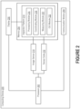
- Figure 2 illustrates an example of a computing device 200 that is able to implement an inspection platform 214 designed to establish the layout of a physical space associated with a structure.
- This physical space could be an interior space or exterior space.
- the inspection platform 214 can establish the layout based on an analysis of image(s) of the physical space. As further discussed below, these image(s) can be acquired during a guided measurement operation in which a user is prompted to pan the computing device 200 to capture a panorama of the physical space.
- the term "panorama” may be used to refer to an image that represents a wide view of the physical space.
- panoramas offer an unbroken view of at least a 180 degree field of view (FOV) along the horizontal plane, though panoramas could offer an unbroken view of a 360 degree FOV along the horizontal plane.
- FOV field of view
- the inspection platform 214 may be able to determine locations of junctures that correspond to the periphery of the physical space and then infer its dimensions (and thus, its layout) based on those locations.
- the computing device 200 can include a processor 202, memory 204, display 206, communication module 208, image sensor 210, and sensor suite 212. Each of these components is discussed in greater detail below. Those skilled in the art will recognize that different combinations of these components may be present depending on the nature of the computing device 200.
- the processor 202 can have generic characteristics similar to general-purpose processors, or the processor 202 may be an application-specific integrated circuit (ASIC) that provides control functions to the computing device 200. As shown in Figure 2 , the processor 202 can be coupled to all components of the computing device 200, either directly or indirectly, for communication purposes.
- ASIC application-specific integrated circuit
- the memory 204 may be comprised of any suitable type of storage medium, such as static random-access memory (SRAM), dynamic random-access memory (DRAM), electrically erasable programmable read-only memory (EEPROM), flash memory, or registers.
- SRAM static random-access memory
- DRAM dynamic random-access memory
- EEPROM electrically erasable programmable read-only memory
- flash memory or registers.
- the memory 204 can also store data generated by the processor 202 (e.g., when executing the modules of the inspection platform 214).
- the memory 204 is merely an abstract representation of a storage environment.
- the memory 204 could be comprised of actual memory chips or modules.
- the display 206 can be any mechanism that is operable to visually convey information to a user.
- the display 206 may be a panel that includes light-emitting diodes (LEDs), organic LEDs, liquid crystal elements, or electrophoretic elements.
- the display 206 is touch sensitive. Thus, a user may be able to provide input to the inspection platform 214 by interacting with the display 206.
- the communication module 208 may be responsible for managing communications between the components of the computing device 200, or the communication module 208 may be responsible for managing communications with other computing devices (e.g., server system 108 of Figure 1 ).
- the communication module 208 may be wireless communication circuitry that is designed to establish communication channels with other computing devices. Examples of wireless communication circuitry include integrated circuits (also referred to as "chips") configured for Bluetooth, Wi-Fi, NFC, and the like.
- the image sensor 210 may be any electronic sensor that is able to detect and convey information in order to generate image data. Examples of image sensors include charge-coupled device (CCD) sensors and complementary metal-oxide semiconductor (CMOS) sensors.
- CCD charge-coupled device
- CMOS complementary metal-oxide semiconductor
- the image sensor 210 may be implemented in a camera module (or simply "camera") that is implemented in the computing device 200. In some embodiments, the image sensor 210 is one of multiple image sensors implemented in the computing device 200. For example, the image sensor 210 could be included in a front- or rear-facing camera on a mobile phone.
- the computing device 200 may include a motion sensor whose output is indicative of motion of the computing device 200 as a whole.
- motion sensors include multi-axis accelerometers and gyroscopes.
- the motion sensor is implemented in an inertial measurement unit (IMU) that measures the force, angular rate, or orientation of the computing device 200.
- IMU inertial measurement unit
- the IMU may accomplish this through the use of one or more accelerometers, one or more gyroscopes, one or more magnetometers, or any combination thereof.
- the computing device 200 may include a proximity sensor whose output is indicative of proximity of the computing device 200 to a nearest obstruction within the field of view of the proximity sensor.
- a proximity sensor may include, for example, an emitter that is able to emit infrared (IR) light and a detector that is able to detect reflected IR light that is returned toward the proximity sensor. These types of proximity sensors are sometimes called laser imaging, detection, and ranging (LiDAR) scanners.
- the computing device 200 may include an ambient light sensor whose output is indicative of the amount of light in the ambient environment.
- the inspection platform 214 is referred to as a computer program that resides within the memory 204.
- the inspection platform 214 could be comprised of software, firmware, or hardware that is implemented in, or accessible to, the computing device 200.
- the inspection platform 214 may include a processing module 216, coordinating module 218, locating module 220, and graphical user interface (GUI) module 222.
- GUI graphical user interface
- Each of these modules can be an integral part of the inspection platform 214.
- these modules can be logically separate from the inspection platform 214 but operate "alongside" it. Together, these modules enable the inspection platform 214 to generate measurements of a physical space, as well as objects contained therein, in an automated manner by guiding a user through a measurement operation.
- the processing module 216 can process data obtained by the inspection platform 214 into a format that is suitable for the other modules. For example, the processing module 216 may apply operations to images generated by the image sensor 210 in preparation for analysis by the other modules of the inspection platform 214. Thus, the processing module 216 may despeckle, denoise, or otherwise filter images that are generated by the image sensor 210. Additionally or alternatively, the processing module 216 may adjust properties like contrast, saturation, and gain in order to improve the outputs produced by the other modules of the inspection platform 214.
- the processing module 216 may also proceed data obtained from the sensor suite 212 in preparation for analysis by the other modules of the inspection platform 214.
- the inspection platform 214 may utilize data that is generated by a motion sensor in order to better understand data that is generated by the image sensor 210.
- the inspection platform 214 may programmatically combine images generated by the image sensor 210 based on measurements generated by the motion sensor, so as to create a panorama of the physical space.
- the inspection platform 214 may determine, based on the measurements, an approximate location of each image generated by the image sensor 210 and then use those insights to estimate dimensions of the physical space and objects contained therein. To accomplish this, the measurements generated by the motion sensor must be temporally aligned with the images generated by the image sensor 210.
- the processing module 216 may be responsible for ensuring that these data are temporally aligned with one another, such that the inspection platform 214 can readily identify the measurement(s) that correspond to each image.
- the coordinating module 218 may be responsible for determining and/or cataloguing the locations of junctures. Assume, for example, that a user is interested in establishing the dimensions of a physical space.
- the periphery of the physical space may be defined by junctures, each of which represents a location where at which a pair of surfaces are joined.
- the inspection platform 214 may request that the user locate the computing device 200 in a certain position (e.g., proximate the center of the physical space) and then capture a panorama of the physical space by panning the computing device 200.
- the coordinating module 218 may be responsible for determining, based on an analysis of the panorama, where the junctures of the physical space are located.
- the trained model may produce, as output, coordinates indicating where a juncture is believed to be located based on pixel-level examination of the panorama. Normally, the trained model will produce a series of outputs that are representative of different junctures of the physical space. Using the series of outputs, the coordinating module 218 can "reconstruct" the physical space, thereby establishing its dimensions. In some embodiments, outputs produced by the sensor suite 212 are used to facilitate the process. For example, a measurement produced by a motion sensor or proximity sensor may allow the coordinating module 218 to gain greater insight into where the computing device 200 is located in the physical space (and thus how to establish the dimensions).
- the measuring module 220 can examine the locations of junctures determined by the coordinating module 218 in order to derive insights into the physical space. For example, the measuring module 220 may calculate a dimension of the physical space based on a comparison of multiple locations (e.g., a width defined by a pair of wall-wall boundaries, or a height defined by the floor-wall and ceiling-wall boundaries ). As another example, the measuring module 220 may generate a 2D or 3D layout using the locations. Thus, the measuring module 220 may be able to construct a 2D or 3D model of the physical space based on insights gained through analysis of a single panorama. In some embodiments, the measuring module 220 is also responsible for cataloging the locations of junctures determined by the coordinating module 218.
- the measuring module 220 may store the locations in a data structure that is associated with either the physical space or a building with which the physical space is associated. Information derived by the measuring module 220, such as dimensions and layouts, can also be stored in the data structure.
- each location is represented using a coordinate system (e.g., a geographic coordinate system such as the Global Positioning System) that is associated with real-world positions, while in other embodiments each location is represented using a coordinate system that is associated with the surrounding environment.
- a coordinate system e.g., a geographic coordinate system such as the Global Positioning System
- each location is represented using a coordinate system that is associated with the surrounding environment.
- the location of each juncture may be defined with respect to the location of the computing device 200.
- the GUI module 222 may be responsible for generating interfaces that can be presented on the display 206. Various types of information can be presented on these interfaces. For example, information that is calculated, derived, or otherwise obtained by the coordinating module 218 and/or measuring module 220 may be presented on an interface for display to the user. As another example, visual feedback may be presented on an interface so as to indicate to the user whether the measurement procedure is being completed properly.
- the inspection platform 214 may not only be responsible for determining the dimensions of a physical space, but also identifying objects contained therein in some embodiments.
- the inspection platform 214 may include a computer vision module that applies one or more types of computer vision models to a panorama provided as input, so as to identify one or more types of objects contained in the corresponding physical space.
- the computer vision models may include multi-class classification, object detection, semantic segmentation, or other deep learning based computer vision approaches to identify multiple types of objects (e.g., different brands of a single object, or different types of objects that are commonly found in the same physical space).
- the computer vision module may also combine several individual computer vision models together to improve accuracy of detection (e.g., apply an object detection model to identify and localize a specific object and then apply a classification model on the localized object to determine kind or quality).
- These computer vision models may be stored in the memory 204 of the computing device 200, or these computer vision models may be stored in a remote memory that is accessible to the computing device 200 (e.g., via the communication module 208).
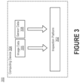
- Figure 3 depicts an example of a communication environment 300 that includes an inspection platform 302 implemented on a computing device.
- the inspection platform 302 may receive and then process several types of data.
- the inspection platform 302 receives image data 306 and sensor data 308.
- the image data 306 may include images that are generated by an image sensor (e.g., image sensor 210 of Figure 2 ) that is implemented in the computing device 304. These images may be discrete images that are captured in rapid succession by the image sensor, or these images may be the individual frames of a video feed that is produced by the image sensor.
- the sensor data 308 may be obtained from one or more of the sensors included in the sensor suite (e.g., sensor suite 212 of Figure 2 ) of the computing device 304.
- the sensor data 308 may include measurements that are generated by a motion sensor, such as an accelerometer or gyroscope, as the computing device 304 is used to generate the image data 306.
- Figure 4 includes a flow diagram of a process 400 for automatically extracting measurements of a structure to enable measurement of arbitrary dimensions, angles, or square footage through analysis of image data and inertial data generated by a computing device.
- the process 400 could be used to establish the height, width, and depth of an interior space of a building, an exterior space of the building, or the building itself.
- the process 400 may be able for use in the insurance industry for assisting in tasks related to insurance claim processes and/or underwriting processes.
- the process 400 is not limited to the insurance industry, and thus could be utilized in any field or scenario where providing automated measurements of a structure is beneficial.
- an inspection platform will receive input that represents a request to measure at least one dimension of a structure (step 401).
- the input is representative of a request to measure a portion of the structure, such as an interior space or exterior space.
- the input normally corresponds to a user either initiating (i.e., opening) the inspection platform or interacting with the inspection platform in such a manner so as to indicate that she is interested in measuring the structure.
- the user may interact with a digital element labeled "Initiate Measuring” or "Begin Measuring” that is viewable on an interface generated by the inspection platform.
- this input could correspond to an instruction that is provided by either a server system to which the computing device is connected or the computing device itself.
- the server system may transmit an instruction to initiate the measurement operation to the inspection platform responsive to a determination that certain conditions have been met, the user has indicated a willingness to complete the measurement operation, etc.
- the inspection platform can then obtain image data that is generated by an image sensor included in the computing device (step 402).
- the image data may include images of at least a portion of the structure to be measured. These images may be representative of static images captured in rapid succession by the image sensor, or these images may be representative of the frames of a video captured by the image sensor.
- the inspection platform may guide the user through capturing the image data at various points of rotation of the computing device to ensure collection of a full 360-degree lateral (i.e., left and right relative to the structure) space and 180-degree vertical (i.e., up and down relative to the structure) space.
- the inspection platform can obtain inertial data that is generated by an inertial sensor included in the computing device (step 403).
- the term "inertial sensor” may be used interchangeably with the term “motion sensor.”
- the nature of the inertial data will depend on the nature of the inertial sensor.
- the inertial sensor is an IMU that includes one or more accelerometers, one or more gyroscopes, one or more magnetometers, or combinations thereof
- the inertial data may include a discrete series of measurements in temporal order. Each measurement may indicate a characteristic of motion of the computing device.
- the measurements may indicate rotational velocity and/or acceleration of the computing device over an interval of time corresponding to generation of the image data.
- the generation of image data and inertial data may be performed simultaneously by the computing device.
- the temporal relationship between the image data and inertial data may allow the inspection platform to gain insights into the position of the computing device with respect to the structure.
- the inspection platform can then combine, based on the inertial data, the different images included in the image data to create a panorama of at least a portion of the structure (step 404).
- the processes herein are described in the context of panoramas; however, those skilled in the art will recognize that the processes may be similarly applicable to images that are not wide-angle representations of a structure.
- the inspection platform may employ algorithms that are designed to combine or "stitch" the different images together so as to create an equirectangular projection of the structure.
- the algorithms overcome the limitations of existing approaches by using line matching techniques in contrast to the feature matching techniques that are normally practiced by those existing approaches.
- line matching techniques may allow the algorithms to optimally perform relative to the structures that are typically of interest (e.g., the interior spaces of buildings).
- the algorithms may estimate the focal length in a manner that is unique with respect to existing approaches. For example, through line matching, the algorithms may estimate the focal length of the image sensor associated with generation of the panorama and then further utilize the measurements included in the inertial data to determine an approximate location of each captured image relative to geography associated with the structure.
- the inspection platform can determine the location of junctures of the structure (step 405), preferably utilizing the panorama of at least a portion of the structure.
- the inspection platform may utilize the panorama to identify the locations of junctures that are representative of floor-wall, ceiling-wall, or wall-wall boundaries.
- the inspection platform may utilize the panorama to compute, infer, or otherwise establish characteristics of other physical features of the structure.
- the inspection platform may be able to determine the curvature of the surfaces - namely, the walls, ceilings, or floors - that make up the structure.
- the algorithms executed by the inspection platform may preferably operate on the panorama to determine the locations of structural intersections like junctures.
- the inspection platform can determine structural aspects (also referred to as "physical aspects") of the structure (step 406). For example, the inspection platform may determine the location of all walls, ceilings, and floors in a 3D spatial representation by combining its knowledge of juncture locations and surface curvature.
- the inspection platform is further configured to estimate the boundaries of some or all of the objects that are present in the panorama (step 407).
- the inspection platform may identify salient objects (e.g., fixtures, appliances, furniture, animals) that are present in the panorama.
- the boundaries of a given object could be identified, for example, by estimating the 3D dimensions of aspects present in the imaged portion of the structure and then using those aspects for reference.
- the estimated dimensions (and measurements of aspects of the structure) are estimated to a scale factor for consistency purposes. The final scaled values may be regressed relative to the distance between the computing device and ground.
- the final scaled values may be regressed relative to the sizes of the salient objects identified in the panorama (and thus present in the structure).
- the inspection platform may also be configured to geographically label - a process referred to as "geo-tagging" - one or more aspects of the structure or the salient objects contained therein.
- the inspection platform can then produce an output that is representative of the insights gained through analysis of the panorama (step 408).
- the inspection platform may generate a manipulable 3D image that is presented by the computing device for display to the user.
- the manipulable 3D image may depict user- or platform-selected dimensions estimated for the structure or the salient objects contained therein.
- the manipulable 3D image is generated by combining the determined physical aspects of the structure with the panorama, so as to enable the user to manipulate the 3D image relative to a selected viewing angle.
- Measurements determined by the inspection platform e.g., through analysis of the panorama
- the interface on which the 3D image is presented may be a "point-and-click interface" that is responsive to selections made by the user. For example, the user may be permitted to identify additional measurements to be generated by selecting one or more locations within the bounds of the 3D image. These location(s) may be associated with physical aspects of the structure, or these location(s) may be associated with a salient object contained in the structure.
- the inspection platform generates and then provides an overlay on the manipulable 3D image that is meant to controllably guide the user through the image data capture process.
- visual indicia may be provided on the interface to indicate determined structural damage relating to physical aspects of the structure.
- the inspection platform discovers that a given physical aspect is abnormal in appearance. This can be accomplished by determining (e.g., based on an output produced by a computer vision model) that the given physical aspect is dissimilar from other physical aspects of the same type. This abnormality may be indicative of damage to the given physical aspect.
- a visual indicium e.g., a bounding box or digital element in a certain color
- a visual indicium may be provided on the interface to identify the abnormality. This can be done by the inspection platform to visually identify the risks, hazards, features, or material types that are associated with internal and external spaces. Examples of risks and hazards for interior spaces include exposed wires, presence of animals, issues related to water heaters, presence or absence of non-combustible materials, wood-burning stoves, issues related to plumbing, mold, water damage (e.g., stains), issues related to washing machines, presence or absence of vacant rooms, issues related to electrical components, and the like.
- risks and hazards for exterior spaces include presence of a deck, steps, stairs, porch, or railings, presence of a pool or pool-related features and components, presence of yard-related features and components, presence of propane task, presence of natural features (e.g., lakes, ponds, or streams) in proximity to a structure, condition of exterior portion of a structure, signage associated with a structure, presence of cages or enclosures for animals, presence of boarded ingress points (e.g., doors and windows), presence of clutter or debris, type of structure (e.g., whether the structure is a mobile or modular home), presence of tarps (e.g., on the roof), presence of bars (e.g., on the doors or windows), and the like.
- natural features e.g., lakes, ponds, or streams
- the types of objects contained in a structure will normally depend on the nature of the structure. If, for example, the imaged portion of the structure is an interior space, then the panorama may be of a bathroom with corresponding fixtures, a kitchen with corresponding fixtures, a laundry room with corresponding fixtures, a common area with associated fixtures, a utility closet with associated fixtures, etc. Meanwhile, if the imaged portion of the structure is an exterior space, then the panorama may be of the construction materials used for exterior construction, outbuildings (e.g., garages and playscapes), yard components (e.g., water features and garden features), exterior components (e.g., faucets, gutters, and condensate drain lines), etc.
- outbuildings e.g., garages and playscapes
- yard components e.g., water features and garden features
- exterior components e.g., faucets, gutters, and condensate drain lines
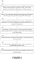
- Figure 5 includes a flow diagram of a process 500 for facilitating a guided procedure for modeling an interior space of a structure using an inspection platform that is executing on a computing device. While the process 500 is described in the context of an interior space, those skilled in the art will recognize that aspects of the process 500 may be similarly appliable to modeling an exterior space.
- the inspection platform will receive input that is indicative of a request to establish the layout of an interior space that includes a series of junctures, each of which represents a point at which a different pair of surfaces are joined (step 501).
- Step 501 of Figure 5 may be substantially similar to step 401 of Figure 4 .
- a user may be able to indicate whether she is interested in establishing a 2D or 3D layout of the interior space. If the user is interested in establishing a 2D layout of the interior space, the inspection platform may only catalogue, store, or otherwise record information regarding wall-wall boundaries. Conversely, if the user is interested in establishing a 3D layout of the interior space, the inspection platform may catalogue, store, or otherwise record information regarding floor-wall, ceiling-wall, and wall-wall boundaries.
- the inspection platform can then instruct the user to generate a panorama by panning the computing device while an image sensor generates one or more images of the interior space (step 502).
- the computing device will normally generate at least two images of the interior space and then combine or "stitch" those images together to create the panorama.
- the panorama may be representative of multiple images with overlapping portions that are joined together - usually by the operating system of the computing device - to collectively represent the interior space.
- the inspection platform can apply a trained model to the panorama to produce an output that is representative of a juncture predicted by the trained model based on an analysis of the panorama (step 503).
- a trained model may output a matrix in which each entry indicates whether the corresponding pixel corresponds to a juncture.
- the value may also indicate the type of juncture (e.g., whether the juncture is representative of a floor-wall, ceiling-wall, or wall-wall boundary). With these values, the inspection platform may be able to define the juncture in the context of the panorama, for example, by identifying which pixels correspond to the juncture.
- the inspection platform may cause display of at least a portion of the panorama with a graphical element overlaid thereon to indicate a location of the juncture that is predicted by the trained model (step 504).
- the output is one of a series of outputs produced by the trained model, each of which is representative of a separate juncture that is predicted by the trained model based on an analysis of the panorama. Accordingly, while each juncture may be represented using a line that overlays the panorama, the panorama may have one or more bounding boxes overlaid thereon as shown in Figure 6 .
- Each bounding box may have four sides, namely, a first side that is representative of the floor-wall boundary, a second side that is representative of the ceiling-wall boundary, and third and fourth sides that are representative of wall-wall boundaries.
- first and second sides are normally roughly parallel to one another and roughly orthogonal to the third and fourth sides.
- the bounding box may not be rectangular due to the distortion of the panorama.
- the bounding boxes that define the walls of an interior space tend to "bulge" along at least one side.
- Graphical elements may be overlaid on the panorama after the panorama has been fully captured, or graphical elements may be overlaid on the panorama as the panorama is being captured.
- the inspection platform may apply the trained model to the panorama in real time (e.g., to columns of pixels) and then populate graphical elements as appropriate.
- the inspection platform may also be able to establish the layout of the interior space based on the outputs produced by the trained model (step 505).
- the outputs may be representative of junctures that are predicted by the trained model based on an analysis of the panorama.
- the inspection platform may infer, predict, or otherwise establish a spatial position in the context of a coordinate system (e.g., defined with respect to the interior space). With these spatial positions, the inspection platform can determine the layout of the interior space. Thereafter, the inspection platform may encode information regarding the layout in a data structure that is associated with the interior space (step 506). For example, the inspection platform may encode the spatial positions of the junctures, the dimensions of the walls, the height of the ceiling, etc.
- the data structure is normally stored in a memory that is internal to the computing device on which the inspection platform is executing.
- the inspection platform could alternatively or additionally cause transmission of the data structure to a destination external to the computing device (step 507).
- the data structure could be transmitted to another computing device (e.g., server system 108 of Figure 1 ) to which the computing device is communicatively connected.
- Figure 7 includes a flow diagram of another process 700 for facilitating a guided procedure for modeling an interior space using an inspection platform that is executing on a computing device.
- the inspection platform may receive input that is indicative of a request from a user to establish the layout of an interior space that includes a series of junctures (step 701), each of which represents a point at which a different pair of surfaces are joined.
- a series of junctures (step 701), each of which represents a point at which a different pair of surfaces are joined.
- the inspection platform may instruct the user to generate a panorama by panning an image sensor across the interior space (step 702). This can be accomplished using the camera housed in a computing device that is associated with the user.
- the inspection platform resides on the computing device, while in other embodiments the inspection platform resides on another computing device to which the computing device is communicatively connected.
- the inspection platform may configure a capture session so that the panorama is made available by the operating system after being generated by the camera. For instance, the inspection platform may cause the capture session to be customized by configuring a capture parameter of the camera based on a characteristic of the interior space.
- the resolution, focus, or flash could be altered based on the ambient light level, distance to wall, location in interior space, etc. These characteristics of the interior space may be determined based on an output produced by a sensor included in a sensor suite (e.g., sensor suite 212 of Figure 2 ) of the computing device.
- a sensor suite e.g., sensor suite 212 of Figure 2
- the inspection platform can then acquire the panorama of the interior space that is generated by the image sensor (step 703).
- the inspection platform may obtain the panorama directly from the operating system.
- the inspection platform may receive the panorama from across a network (e.g., via communication module 208 of Figure 2 ).
- the inspection platform can apply a trained model to the panorama to produce a series of outputs (step 704).
- Each output in the series of outputs may be representative of a juncture that is predicted by the trained model based on an analysis of the panorama.
- the trained model may be configured to perform pixel-wise classification of pixel data corresponding to the panorama in a columnar manner to produce the series of outputs.
- the inspection platform establishes the layout of the interior space based on the series of outputs (step 705). For example, the inspection platform may calculate the dimensions of the interior space based on the series of outputs and then create a 2D floor plan for the interior space that is based on the dimensions. As another example, the inspection platform may calculate the dimensions of the interior space based on the series of outputs and then create a 3D floor plan for the interior space that is based on the dimensions. Whether the floor plan is 2D or 3D may depend on the type(s) of junctures that are predicted by the inspection platform. Moreover, the inspection platform can encode information regarding the layout in a data structure that is associated with the interior space (step 706). Step 706 of Figure 7 may be substantially similar to step 506 of Figure 5 .
- the inspection platform is configured to provide feedback to the user during the capture session in which the panorama is captured.
- the inspection platform may cause display of the panorama on an interface (step 707) and then indicate a location of each juncture that is predicted by the trained model by overlaying at least one bounding box on the panorama (step 708).
- the perimeter of each bounding box is typically defined by a set of four outputs. Normally, the set of four outputs includes a first output representing a floor-wall boundary, a second output representing a ceiling-wall boundary, and third and fourth outputs representing different wall-wall boundaries.
- steps 707-708 are performed in near real time.
- bounding boxes may be overlaid on the panorama as the image sensor is panned across the interior space (and the panorama is presented on the display of the computing device).
- steps 707-708 are performed after the panorama is generated.
- steps 707-708 may be performed by the inspection platform in response to receiving input indicative of a selection of the panorama by the user.
- Figure 8 includes a flow diagram of a process 800 for identifying objects that are contained in a physical space for which a panorama is available.
- This physical space could be an interior space or exterior space.
- objects are identifying by applying computer vision models directly to the panorama, while in other embodiments the panorama is projected back into a normal perspective image before the computer vision models are applied. Additionally or alternatively, computer vision models may be applied to some or all of the images that collectively form the panorama.
- an inspection platform can acquire a panorama of the physical space that is generated by an image sensor of a computing device (step 801).
- the panorama is normally generated as part of a measurement operation in which a user pans the image sensor across the physical space.
- the user may be guided by the inspection platform to systematically pan the image sensor across a portion of the physical space (e.g., so as to image lateral space in 360 degrees), or the user may be guided by the inspection platform to systematically pan the image sensor across the entire physical space (e.g., so as to image lateral space in 360 degrees and vertical space in 360 degrees).
- the inspection platform may apply one or more classification models to the panorama (step 802), so as to identify one or more types of objects included in the panorama.
- Each classification model may be designed and then trained to identify a different type of object.
- the classification models may include a first classification model that is trained to identify stoves, a second classification model that is trained to identify water heaters, a third classification model that is trained to identify water stains, etc. Accordingly, the classification models may be trained to identify objects that are associated with some degree of risk, as well as visual indicia of damage caused by those objects.
- the classification models that are applied to the panorama may depend on the nature of the physical space. Assume, for example, that a user specifies that she is interested in generating a panorama of a kitchen and then proceeds to image the kitchen as discussed above. In such a situation, the inspection platform may only apply those classification models that have been deemed suitable or appropriate for kitchens. As an example, the inspection platform may apply classification models associated with stoves, refrigerators, and water stains but not washing machines or porches. This may advantageously allow the inspection platform to conserve computational resources since not every classification model is necessarily applied to every panorama obtained by the inspection platform.
- the inspection platform may access a data structure in which each classification model is programmatically associated with one or more types of physical spaces. For example, the classification model trained to identify stoves may be labelled as appropriate for kitchens, while the classification model trained to identify water stains may be labelled as appropriate for kitchens, bathrooms, bedrooms, and exterior spaces. These relationships may be manually defined (e.g., at the time of training), or these relationships may be automatically determined by the inspection platform (e.g., based on an analysis of a pool of panoramas to which each classification model available to the inspection platform may be applied).
- each classification model may produce, as output, a bounding box or pixel-wise classification that defines the pixels determined to represent an instance of the corresponding type of object.
- the inspection platform may obtain several bounding boxes that are associated with different types of objects. For example, in the event that the panorama is associated with a kitchen, the inspection platform may ultimately obtain a first bounding box that identifies the stove, a second bounding box that identifies the refrigerator, a third bounding box that identifies a water stain, etc.
- the inspection platform is also configured to determine the dimensions of each object identified by a classification model based on analysis of the panorama (step 803).
- the inspection platform may identify its boundaries based on the output produced by the classification model and then compute, infer, or otherwise establish its dimensions based on the boundaries.
- the dimensions could be determined in an absolute sense (e.g., based solely on analysis of its boundaries), or the dimensions could be determined in a relative sense (e.g., by considering its boundaries in the context of junctures of the physical space, other objects in the physical space, etc.).
- the inspection platform can encode information regarding the outputs, if any, produced by the classification model(s) in a data structure that is associated with the physical space (step 804).
- Step 804 of Figure 8 may be substantially similar to steps 506 and 706 of Figures 5 and 7 , respectively, except that the information pertains to an object rather than the physical space.
- the inspection platform may encode the dimensions of the object in the data structure.
- the inspection platform may encode the boundaries of the bounding box (e.g., in terms of pixel coordinates of the panorama) determined for the object.
- the inspection platform may attempt to limit the inaccuracy by adjusting the predicted locations.
- the inspection platform can be configured to mathematically model the spatial locations of individual junctures (and between pairs of junctures) based on the panorama and/or outputs generated by other sensors included in the computing device.
- an output may be produced that identifies an instance of a given type of object.
- information regarding the object may be presented on an interface for review by the user.
- the user may be able to confirm or deny the instance of the object as identified by the classification model.
- the inspection platform may be able to prompt or permit the user to provide information regarding the instance of the object.
- the inspection platform may proactively ask the user to provide additional information regarding the stove (e.g., fuel type and age).
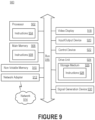
- FIG. 9 is a block diagram illustrating an example of a processing system 900 in which at least some operations described herein can be implemented.
- components of the processing system 900 may be hosted on a computing device that includes an inspection platform, or components of the processing system 900 may be hosted on a computing device with which a panorama of a physical space is captured.
- the processing system 900 may include a central processing unit (“processor") 902, main memory 906, non-volatile memory 910, network adapter 912, video display 918, input/output devices 920, control device 922 (e.g., a keyboard or pointing device), drive unit 924 including a storage medium 926, and signal generation device 930 that are communicatively connected to a bus 916.
- the bus 916 is illustrated as an abstraction that represents one or more physical buses or point-to-point connections that are connected by appropriate bridges, adapters, or controllers.
- the bus 916 can include a system bus, a Peripheral Component Interconnect (PCI) bus or PCI-Express bus, a HyperTransport or industry standard architecture (ISA) bus, a small computer system interface (SCSI) bus, a universal serial bus (USB), inter-integrated circuit (I 2 C) bus, or an Institute of Electrical and Electronics Engineers (IEEE) standard 1394 bus (also referred to as "Firewire").
- PCI Peripheral Component Interconnect
- ISA industry standard architecture
- SCSI small computer system interface
- USB universal serial bus
- I 2 C inter-integrated circuit
- IEEE Institute of Electrical and Electronics Engineers
- machine-readable medium and “storage medium” should be taken to include a single medium or multiple media (e.g., a centralized/distributed database and/or associated caches and servers) that store one or more sets of instructions 928.
- routines executed to implement the embodiments of the disclosure may be implemented as part of an operating system or a specific application, component, program, object, module, or sequence of instructions (collectively referred to as "computer programs").
- the computer programs typically comprise one or more instructions (e.g., instructions 904, 908, 928) set at various times in various memory and storage devices in a computing device.
- the instruction(s) When read and executed by the processors 902, the instruction(s) cause the processing system 900 to perform operations to execute elements involving the various aspects of the present disclosure.
- machine- and computer-readable media include recordable-type media, such as volatile memory devices and non-volatile memory devices 910, removable disks, hard disk drives, and optical disks (e.g., Compact Disk Read-Only Memory (CD-ROMS) and Digital Versatile Disks (DVDs)), and transmission-type media, such as digital and analog communication links.
- recordable-type media such as volatile memory devices and non-volatile memory devices 910
- removable disks such as removable disks, hard disk drives, and optical disks (e.g., Compact Disk Read-Only Memory (CD-ROMS) and Digital Versatile Disks (DVDs)
- CD-ROMS Compact Disk Read-Only Memory
- DVDs Digital Versatile Disks
- the network adapter 912 enables the processing system 900 to mediate data in a network 914 with an entity that is external to the processing system 900 through any communication protocol supported by the processing system 900 and the external entity.
- the network adapter 912 can include a network adaptor card, a wireless network interface card, a router, an access point, a wireless router, a switch, a multilayer switch, a protocol converter, a gateway, a bridge, bridge router, a hub, a digital media receiver, a repeater, or any combination thereof.
Landscapes
- Engineering & Computer Science (AREA)
- Physics & Mathematics (AREA)
- General Physics & Mathematics (AREA)
- Theoretical Computer Science (AREA)
- Geometry (AREA)
- Computer Hardware Design (AREA)
- Evolutionary Computation (AREA)
- General Engineering & Computer Science (AREA)
- Computer Vision & Pattern Recognition (AREA)
- Multimedia (AREA)
- Signal Processing (AREA)
- Pure & Applied Mathematics (AREA)
- Software Systems (AREA)
- Mathematical Analysis (AREA)
- Computational Mathematics (AREA)
- Artificial Intelligence (AREA)
- Structural Engineering (AREA)
- Medical Informatics (AREA)
- Mathematical Optimization (AREA)
- Civil Engineering (AREA)
- Architecture (AREA)
- Quality & Reliability (AREA)
- Radar, Positioning & Navigation (AREA)
- Remote Sensing (AREA)
- Image Analysis (AREA)
- Image Processing (AREA)
Claims (12)
- Procédé mis en œuvre par un programme d'ordinateur s'exécutant sur un dispositif informatique (200), le procédé comprenant :la réception (701) d'une entrée qui est indicative d'une requête d'établissement d'une disposition d'un espace intérieur qui comporte une série de jointures, chacune desquelles représente un point au niveau duquel une paire différente de surfaces sont jointes ;le fait d'ordonner (702) à un utilisateur de générer une image panoramique en effectuant un mouvement panoramique avec un appareil de prise de vues sur tout l'espace intérieur ;le fait d'amener une session de capture à être personnalisée en configurant un paramètre de capture de l'appareil de prise de vues, dans lequel le paramètre de capture comprend une résolution d'images acquises ;l'acquisition, par l'appareil de prise de vues, d'au moins deux images de l'espace intérieur selon le paramètre de capture ;l'acquisition, par un capteur de mouvement du dispositif informatique, de données inertielles simultanément avec l'acquisition des au moins deux images ;la génération d'une image panoramique équirectangulaire numérique sur la base des données inertielles et des au moins deux images ;l'application (704) d'un modèle entraîné à l'image panoramique équirectangulaire numérique pour produire une série de sorties, dans lequel chaque sortie de la série de sorties est représentative d'une jointure séparée prédite par le modèle entraîné sur la base d'une analyse de l'image panoramique équirectangulaire ;la fourniture d'indices visuels pour indiquer un aspect anormal d'une structure dans l'espace intérieur, dans lequel l'aspect anormal de la structure comprend un ou plusieurs risques ou dangers ; etle fait d'amener (707) l'affichage d'au moins une portion de l'image panoramique équirectangulaire numérique avec des éléments graphiques superposés sur celle-ci sous la forme d'un cadre de sélection, dans lequel un périmètre du cadre de sélection est défini par un ensemble de quatre sorties, l'ensemble de quatre sorties étant un sous-ensemble de la série de sorties, et dans lequel l'ensemble de quatre sorties comporte une première sortie représentant une limite plancher-mur, une deuxième sortie représentant une limite plafond-mur, et des troisième et quatrième sorties représentant différentes limites mur-mur.
- Procédé selon la revendication 1, dans lequel le procédé comprend en outre :l'établissement (705) de la disposition de l'espace intérieur sur la base de la série de sorties ;le codage (706) d'informations concernant la disposition dans une structure de données qui est associée à l'espace intérieur ; etle fait d'amener l'émission de la structure de données vers une destination externe au dispositif informatique.
- Procédé selon la revendication 1, comprenant en outre l'alignement temporel des données inertielles avec les au moins deux images ; et
dans lequel l'image panoramique équirectangulaire numérique est générée en combinant les au moins deux images sur la base de la série de mesures. - Procédé selon la revendication 1, comprenant en outre :
la détermination d'une dimension de l'espace intérieur sur la base d'une analyse par :la prédiction, pour chaque sortie de la série de sorties, d'une position spatiale de la jointure correspondante dans un contexte d'un système de coordonnées, etle calcul de la dimension de l'espace intérieur sur la base des positions spatiales prédites pour la série de sorties ; etle codage de la dimension dans une structure de données qui est associée à l'espace intérieur. - Procédé selon la revendication 4, comprenant en outre :
l'application d'un second modèle à l'image panoramique équirectangulaire numérique pour produire une sortie qui est représentative d'un objet qui est prédit par le second modèle. - Procédé selon la revendication 4, comprenant en outre l'application d'un second modèle à l'image panoramique équirectangulaire numérique pour produire une sortie représentative d'un cadre de sélection ou d'une classification pixel par pixel qui comporte des pixels de deux images ou plus qui correspondent à un objet.
- Procédé selon la revendication 6, dans lequel le second modèle est l'un d'une série de modèles qui sont appliqués à l'image panoramique équirectangulaire numérique à des fins de classification d'objet, et dans lequel chaque modèle de la série de modèles est entraîné pour prédire un type d'objet différent.
- Procédé selon la revendication 7, comprenant en outre le codage d'informations concernant l'objet dans la structure de données qui est associée à l'espace intérieur.
- Procédé selon la revendication 4, comprenant en outre :l'estimation, sur la base des au moins deux images, de longueurs focales nécessaires pour générer l'image panoramique équirectangulaire numérique ;la détermination, sur la base d'une série de mesures, d'un emplacement de chacune des au moins deux images par rapport à une géographie de l'espace intérieur ; etla combinaison des au moins deux images sur la base de l'emplacement.
- Procédé selon la revendication 4, comprenant en outre :le fait d'amener l'affichage de l'image panoramique équirectangulaire numérique sur une interface ; etl'indication d'un emplacement de chaque jointure qui est prédit par le modèle en superposant au moins un cadre de sélection sur l'image panoramique équirectangulaire numérique, dans lequel un périmètre du cadre de sélection est défini par un ensemble de quatre sorties, et dans lequel l'ensemble de quatre sorties comporte une première sortie représentant une limite plancher-mur, une deuxième sortie représentant une limite plafond-mur, et des troisième et quatrième sorties représentant différentes limites mur-mur.
- Procédé selon la revendication 10, dans lequel ledit fait d'amener et ladite indication sont réalisés en temps quasi réel pendant qu'un appareil de prise de vues du dispositif informatique effectue un mouvement panoramique sur tout l'espace intérieur pour générer l'image panoramique équirectangulaire numérique.
- Procédé selon la revendication 4, dans lequel le paramètre de capture comprend en outre un réglage de flash.
Applications Claiming Priority (2)
| Application Number | Priority Date | Filing Date | Title |
|---|---|---|---|
| US202063091149P | 2020-10-13 | 2020-10-13 | |
| PCT/US2021/054796 WO2022081717A1 (fr) | 2020-10-13 | 2021-10-13 | Génération de mesures de structures et d'environnements physiques par analyse automatisée de données de capteur |
Publications (3)
| Publication Number | Publication Date |
|---|---|
| EP4229552A1 EP4229552A1 (fr) | 2023-08-23 |
| EP4229552A4 EP4229552A4 (fr) | 2024-03-06 |
| EP4229552B1 true EP4229552B1 (fr) | 2025-04-23 |
Family
ID=81079292
Family Applications (1)
| Application Number | Title | Priority Date | Filing Date |
|---|---|---|---|
| EP21881003.4A Active EP4229552B1 (fr) | 2020-10-13 | 2021-10-13 | Génération de mesures de structures et d'environnements physiques par analyse automatisée de données de capteur |
Country Status (4)
| Country | Link |
|---|---|
| US (3) | US11699001B2 (fr) |
| EP (1) | EP4229552B1 (fr) |
| CN (2) | CN117744196A (fr) |
| WO (1) | WO2022081717A1 (fr) |
Families Citing this family (8)
| Publication number | Priority date | Publication date | Assignee | Title |
|---|---|---|---|---|
| EP3907725A1 (fr) * | 2020-05-06 | 2021-11-10 | Admesy B.V. | Procédé et installation pour la réalisation d'une série de mesures optiques à l'aide d'un système d'imagerie 2d |
| US11769245B2 (en) * | 2021-10-21 | 2023-09-26 | Goodrich Corporation | Systems and methods of monitoring cargo load systems for damage detection |
| US12449250B2 (en) | 2021-12-10 | 2025-10-21 | Lexisnexis Risk Solutions Fl Inc. | Provoking movement of computing devices with augmented reality features |
| US12505618B2 (en) * | 2022-02-02 | 2025-12-23 | Tencent America LLC | Manhattan layout estimation using geometric and semantic information |
| WO2024030525A1 (fr) | 2022-08-03 | 2024-02-08 | Schlumberger Technology Corporation | Détermination et traitement automatisés de qualité d'enregistrement pour quantification d'émission de polluants |
| US12577871B2 (en) | 2022-08-03 | 2026-03-17 | Schlumberger Technology Corporation | Linear cut generation method for sensor inversion constraint imposition |
| AU2024284054A1 (en) | 2023-06-09 | 2026-01-08 | Schlumberger Technology B.V. | Emission detecting camera placement planning using 3d models |
| US20250078240A1 (en) * | 2023-08-31 | 2025-03-06 | Schlumberger Technology Corporation | Panoramic images for improved methane camera commissioning, interpretation, and remote operation |
Family Cites Families (253)
| Publication number | Priority date | Publication date | Assignee | Title |
|---|---|---|---|---|
| US6657667B1 (en) * | 1997-11-25 | 2003-12-02 | Flashpoint Technology, Inc. | Method and apparatus for capturing a multidimensional array of overlapping images for composite image generation |
| US20030210228A1 (en) * | 2000-02-25 | 2003-11-13 | Ebersole John Franklin | Augmented reality situational awareness system and method |
| JP4244973B2 (ja) * | 2005-08-03 | 2009-03-25 | ソニー株式会社 | 撮像システムとカメラ制御装置およびパノラマ画像表示方法とプログラム |
| US20070081081A1 (en) * | 2005-10-07 | 2007-04-12 | Cheng Brett A | Automated multi-frame image capture for panorama stitching using motion sensor |
| US8564640B2 (en) * | 2007-11-16 | 2013-10-22 | Tenebraex Corporation | Systems and methods of creating a virtual window |
| US20100275018A1 (en) * | 2007-12-20 | 2010-10-28 | Pedersen Thomas Jam | System and method for conversion and distribution of graphical objects |
| US8217956B1 (en) * | 2008-02-29 | 2012-07-10 | Adobe Systems Incorporated | Method and apparatus for rendering spherical panoramas |
| WO2010025309A1 (fr) * | 2008-08-28 | 2010-03-04 | Zoran Corporation | Assemblage panoramique rapide et efficace dans des téléphones mobiles ou des appareils photo |
| US9766089B2 (en) * | 2009-12-14 | 2017-09-19 | Nokia Technologies Oy | Method and apparatus for correlating and navigating between a live image and a prerecorded panoramic image |
| JP2011155361A (ja) * | 2010-01-26 | 2011-08-11 | Sony Corp | 撮像装置、撮像制御方法、プログラム |
| JP5504915B2 (ja) * | 2010-01-26 | 2014-05-28 | ソニー株式会社 | 撮像制御装置、撮像制御方法、プログラム |
| JP5686244B2 (ja) * | 2010-12-21 | 2015-03-18 | ソニー株式会社 | 表示制御装置、表示制御方法、及び、プログラム |
| US8600194B2 (en) * | 2011-05-17 | 2013-12-03 | Apple Inc. | Positional sensor-assisted image registration for panoramic photography |
| US20130099919A1 (en) * | 2011-10-20 | 2013-04-25 | Hon Hai Precision Industry Co., Ltd. | Emergency guiding system and server |
| US20130116922A1 (en) * | 2011-11-08 | 2013-05-09 | Hon Hai Precision Industry Co., Ltd. | Emergency guiding system, server and portable device using augmented reality |
| US9070216B2 (en) * | 2011-12-14 | 2015-06-30 | The Board Of Trustees Of The University Of Illinois | Four-dimensional augmented reality models for interactive visualization and automated construction progress monitoring |
| US8971612B2 (en) * | 2011-12-15 | 2015-03-03 | Microsoft Corporation | Learning image processing tasks from scene reconstructions |
| US10663294B2 (en) * | 2012-02-03 | 2020-05-26 | Eagle View Technologies, Inc. | Systems and methods for estimation of building wall area and producing a wall estimation report |
| US11282287B2 (en) * | 2012-02-24 | 2022-03-22 | Matterport, Inc. | Employing three-dimensional (3D) data predicted from two-dimensional (2D) images using neural networks for 3D modeling applications and other applications |
| US10848731B2 (en) * | 2012-02-24 | 2020-11-24 | Matterport, Inc. | Capturing and aligning panoramic image and depth data |
| US10139985B2 (en) * | 2012-06-22 | 2018-11-27 | Matterport, Inc. | Defining, displaying and interacting with tags in a three-dimensional model |
| US8994540B2 (en) * | 2012-09-21 | 2015-03-31 | Google Inc. | Cover plate for a hazard detector having improved air flow and other characteristics |
| US8570329B1 (en) * | 2012-10-31 | 2013-10-29 | Google Inc. | Subtle camera motions to indicate imagery type in a mapping system |
| US8902322B2 (en) * | 2012-11-09 | 2014-12-02 | Bubl Technology Inc. | Systems and methods for generating spherical images |
| FR2998400B1 (fr) * | 2012-11-21 | 2016-01-15 | Thales Sa | Procede de reconstruction 3d et de mosaiquage 3d panoramique d'une scene |
| IES20120509A2 (en) * | 2012-11-27 | 2014-06-04 | Digitaloptics Corp Europe Ltd | Digital image capture device having a panorama mode |
| US9602720B2 (en) * | 2012-12-10 | 2017-03-21 | Samsung Electronics Co., Ltd. | Photographing apparatus |
| US9648297B1 (en) * | 2012-12-28 | 2017-05-09 | Google Inc. | Systems and methods for assisting a user in capturing images for three-dimensional reconstruction |
| US20140362176A1 (en) * | 2013-01-05 | 2014-12-11 | Patrick A. St. Clair | Spherical panoramic imaging system |
| US9595134B2 (en) * | 2013-05-11 | 2017-03-14 | Mitsubishi Electric Research Laboratories, Inc. | Method for reconstructing 3D scenes from 2D images |
| US10438633B2 (en) * | 2013-05-26 | 2019-10-08 | Pixellot Ltd. | Method and system for low cost television production |
| US10021295B1 (en) * | 2013-06-03 | 2018-07-10 | Amazon Technologies, Inc. | Visual cues for managing image capture |
| US11670046B2 (en) * | 2013-07-23 | 2023-06-06 | Hover Inc. | 3D building analyzer |
| US10861224B2 (en) * | 2013-07-23 | 2020-12-08 | Hover Inc. | 3D building analyzer |
| US9600989B2 (en) * | 2013-09-12 | 2017-03-21 | Google Inc. | Detector unit with multiple integrated sensing systems and visually pleasing housing |
| US20150116691A1 (en) * | 2013-10-25 | 2015-04-30 | Planitar Inc. | Indoor surveying apparatus and method |
| US9787904B2 (en) * | 2013-10-31 | 2017-10-10 | InsideMaps Inc. | Methods and apparatuses for capturing images used for generating 3D models of rooms |
| US20150207988A1 (en) * | 2014-01-23 | 2015-07-23 | Nvidia Corporation | Interactive panoramic photography based on combined visual and inertial orientation tracking |
| WO2015123348A1 (fr) * | 2014-02-11 | 2015-08-20 | Xactware Solutions, Inc. | Système et procédé permettant de générer des plans d'étage informatisés |
| US12190429B2 (en) * | 2014-02-20 | 2025-01-07 | William Ernest Miller | Method and system for construction project management using photo imaging measurements |
| GB2525232A (en) * | 2014-04-17 | 2015-10-21 | Nokia Technologies Oy | A device orientation correction method for panorama images |
| US9977844B2 (en) * | 2014-05-13 | 2018-05-22 | Atheer, Inc. | Method for providing a projection to align 3D objects in 2D environment |
| US9595130B2 (en) * | 2014-06-17 | 2017-03-14 | Chief Architect Inc. | Virtual model navigation methods and apparatus |
| US9575564B2 (en) * | 2014-06-17 | 2017-02-21 | Chief Architect Inc. | Virtual model navigation methods and apparatus |
| US9420176B2 (en) * | 2014-06-19 | 2016-08-16 | Omnivision Technologies, Inc. | 360 degree multi-camera system |
| US9589362B2 (en) * | 2014-07-01 | 2017-03-07 | Qualcomm Incorporated | System and method of three-dimensional model generation |
| US11205305B2 (en) * | 2014-09-22 | 2021-12-21 | Samsung Electronics Company, Ltd. | Presentation of three-dimensional video |
| US10750153B2 (en) * | 2014-09-22 | 2020-08-18 | Samsung Electronics Company, Ltd. | Camera system for three-dimensional video |
| EP3251347A4 (fr) * | 2015-01-28 | 2018-09-19 | Matterport, Inc. | Classification, séparation et affichage d'étages individuels d'un modèle tridimensionnel d'une structure multi-étages d'après des données d'images capturées de la structure multi-étages |
| US9521321B1 (en) * | 2015-02-11 | 2016-12-13 | 360 Lab Llc. | Enabling manually triggered multiple field of view image capture within a surround image mode for multi-lens mobile devices |
| US10210577B1 (en) * | 2015-04-17 | 2019-02-19 | State Farm Mutual Automobile Insurance Company | Electronic device data capture for property insurance quotes |
| US9536452B2 (en) * | 2015-05-13 | 2017-01-03 | Abl Ip Holding Llc | System and method to assist users having reduced visual capability utilizing lighting device provided information |
| US10410413B2 (en) * | 2015-05-29 | 2019-09-10 | Hover Inc. | Image capture for a multi-dimensional building model |
| US9866752B2 (en) * | 2015-06-02 | 2018-01-09 | Qualcomm Incorporated | Systems and methods for producing a combined view from fisheye cameras |
| US10033928B1 (en) * | 2015-10-29 | 2018-07-24 | Gopro, Inc. | Apparatus and methods for rolling shutter compensation for multi-camera systems |
| US10706615B2 (en) * | 2015-12-08 | 2020-07-07 | Matterport, Inc. | Determining and/or generating data for an architectural opening area associated with a captured three-dimensional model |
| US10068385B2 (en) * | 2015-12-15 | 2018-09-04 | Intel Corporation | Generation of synthetic 3-dimensional object images for recognition systems |
| US20170180680A1 (en) * | 2015-12-21 | 2017-06-22 | Hai Yu | Object following view presentation method and system |
| US10977764B2 (en) * | 2015-12-29 | 2021-04-13 | Dolby Laboratories Licensing Corporation | Viewport independent image coding and rendering |
| US10692011B2 (en) * | 2016-01-21 | 2020-06-23 | Verily Life Sciences Llc | Adaptive model-based system to automatically quantify fall risk |
| US20170278308A1 (en) * | 2016-03-23 | 2017-09-28 | Intel Corporation | Image modification and enhancement using 3-dimensional object model based recognition |
| WO2017174412A1 (fr) * | 2016-04-06 | 2017-10-12 | Philips Lighting Holding B.V. | Commande d'un système d'éclairage |
| US10554896B2 (en) * | 2016-05-04 | 2020-02-04 | Insidemaps, Inc. | Stereoscopic imaging using mobile computing devices having front-facing and rear-facing cameras |
| EP3466051A1 (fr) * | 2016-05-25 | 2019-04-10 | GoPro, Inc. | Réduction tridimensionnelle du bruit |
| WO2017203710A1 (fr) * | 2016-05-27 | 2017-11-30 | 楽天株式会社 | Système de génération de modèle tridimensionnel, procédé de génération de modèle tridimensionnel et programme |
| CN109863754B (zh) * | 2016-06-07 | 2021-12-28 | 维斯比特股份有限公司 | 用于直播流化的虚拟现实360度视频相机系统 |
| US10277886B2 (en) * | 2016-07-19 | 2019-04-30 | Gopro, Inc. | Mapping of spherical image data into rectangular faces for transport and decoding across networks |
| WO2018058044A1 (fr) * | 2016-09-23 | 2018-03-29 | Aon Benfield Inc. | Plate-forme, systèmes et procédés d'identification de caractéristiques de propriété et d'entretien de caractéristiques de propriété par une analyse d'imagerie aérienne |
| US10600150B2 (en) * | 2016-10-31 | 2020-03-24 | Adobe Inc. | Utilizing an inertial measurement device to adjust orientation of panorama digital images |
| CN115097937B (zh) * | 2016-11-15 | 2025-04-29 | 奇跃公司 | 用于长方体检测的深度学习系统 |
| JP6116746B1 (ja) * | 2016-11-17 | 2017-04-19 | 株式会社ネクスト | 情報処理装置、情報処理方法、及びプログラム |
| US20180190033A1 (en) * | 2016-12-30 | 2018-07-05 | Facebook, Inc. | Systems and methods for providing augmented reality effects and three-dimensional mapping associated with interior spaces |
| CN110419219A (zh) * | 2017-01-03 | 2019-11-05 | 诺基亚技术有限公司 | 用于视频编码和解码的装置、方法和计算机程序 |
| US20230188384A1 (en) * | 2020-05-10 | 2023-06-15 | David N. Claffey | Method, apparatus, and system for wireless sensing based on multiple groups of wireless devices |
| GB2559157A (en) * | 2017-01-27 | 2018-08-01 | Ucl Business Plc | Apparatus, method and system for alignment of 3D datasets |
| US11043026B1 (en) * | 2017-01-28 | 2021-06-22 | Pointivo, Inc. | Systems and methods for processing 2D/3D data for structures of interest in a scene and wireframes generated therefrom |
| US10248744B2 (en) * | 2017-02-16 | 2019-04-02 | The University Of North Carolina At Chapel Hill | Methods, systems, and computer readable media for acoustic classification and optimization for multi-modal rendering of real-world scenes |
| US10185878B2 (en) * | 2017-02-28 | 2019-01-22 | Microsoft Technology Licensing, Llc | System and method for person counting in image data |
| US10616482B2 (en) * | 2017-03-10 | 2020-04-07 | Gopro, Inc. | Image quality assessment |
| AU2018236433B2 (en) * | 2017-03-17 | 2022-03-03 | Magic Leap, Inc. | Room layout estimation methods and techniques |
| US11218683B2 (en) * | 2017-03-22 | 2022-01-04 | Nokia Technologies Oy | Method and an apparatus and a computer program product for adaptive streaming |
| US10477200B2 (en) * | 2017-04-13 | 2019-11-12 | Facebook, Inc. | Panoramic camera systems |
| US10572970B2 (en) * | 2017-04-28 | 2020-02-25 | Google Llc | Extracting 2D floor plan from 3D GRID representation of interior space |
| US10567630B2 (en) * | 2017-05-12 | 2020-02-18 | Microsoft Technology Licensing, Llc | Image capture using a hinged device with multiple cameras |
| US10319150B1 (en) * | 2017-05-15 | 2019-06-11 | A9.Com, Inc. | Object preview in a mixed reality environment |
| EP3404913B1 (fr) * | 2017-05-16 | 2019-11-06 | Axis AB | Système comprenant une caméra vidéo et un dispositif client et procédé ainsi mis en oeuvre |
| US10992847B2 (en) * | 2017-05-25 | 2021-04-27 | Eys3D Microelectronics, Co. | Image device for generating a 360 degree depth map |
| US10321109B1 (en) * | 2017-06-13 | 2019-06-11 | Vulcan Inc. | Large volume video data transfer over limited capacity bus |
| US10530997B2 (en) * | 2017-07-13 | 2020-01-07 | Zillow Group, Inc. | Connecting and using building interior data acquired from mobile devices |
| US10824867B1 (en) * | 2017-08-02 | 2020-11-03 | State Farm Mutual Automobile Insurance Company | Augmented reality system for real-time damage assessment |
| US10133933B1 (en) * | 2017-08-07 | 2018-11-20 | Standard Cognition, Corp | Item put and take detection using image recognition |
| US10304254B2 (en) * | 2017-08-08 | 2019-05-28 | Smart Picture Technologies, Inc. | Method for measuring and modeling spaces using markerless augmented reality |
| US10477064B2 (en) * | 2017-08-21 | 2019-11-12 | Gopro, Inc. | Image stitching with electronic rolling shutter correction |
| US10395147B2 (en) * | 2017-10-30 | 2019-08-27 | Rakuten, Inc. | Method and apparatus for improved segmentation and recognition of images |
| US10410350B2 (en) * | 2017-10-30 | 2019-09-10 | Rakuten, Inc. | Skip architecture neural network machine and method for improved semantic segmentation |
| US11127129B2 (en) * | 2017-12-14 | 2021-09-21 | The Joan and Irwin Jacobs Technion-Cornell Institute | Techniques for identifying hazardous site conditions in geo-localized enhanced floor plans |
| US11127213B2 (en) * | 2017-12-22 | 2021-09-21 | Houzz, Inc. | Techniques for crowdsourcing a room design, using augmented reality |
| EP3506160B1 (fr) * | 2017-12-28 | 2022-06-01 | Dassault Systèmes | Segmentation sémantique de plans de sol 2d à l'aide d'un classificateur au niveau du pixel |
| EP3506211B1 (fr) * | 2017-12-28 | 2021-02-24 | Dassault Systèmes | Génération de modèles 3d représentant des bâtiments |
| US12361511B2 (en) * | 2018-02-09 | 2025-07-15 | Matterport, Inc. | Accuracy of GPS coordinates associated with image capture locations |
| US11494857B2 (en) * | 2018-02-15 | 2022-11-08 | Flyreel, Inc. | Property inspection system and method |
| US20190266793A1 (en) * | 2018-02-23 | 2019-08-29 | Lowe's Companies, Inc. | Apparatus, systems, and methods for tagging building features in a 3d space |
| US11328102B2 (en) * | 2018-03-29 | 2022-05-10 | Aecom | Digital design tools for building construction |
| US20190303648A1 (en) * | 2018-04-02 | 2019-10-03 | QRI Group, LLC | Smart surveillance and diagnostic system for oil and gas field surface environment via unmanned aerial vehicle and cloud computation |
| US10643386B2 (en) * | 2018-04-11 | 2020-05-05 | Zillow Group, Inc. | Presenting image transition sequences between viewing locations |
| US11093747B2 (en) * | 2018-04-16 | 2021-08-17 | Peerwell, Inc. | Hazard recognition |
| US10950021B2 (en) * | 2018-04-23 | 2021-03-16 | Accenture Global Solutions Limited | AI-driven design platform |
| US10592747B2 (en) * | 2018-04-26 | 2020-03-17 | Fyusion, Inc. | Method and apparatus for 3-D auto tagging |
| JP7163057B2 (ja) * | 2018-04-26 | 2022-10-31 | キヤノン株式会社 | 撮像装置、撮像方法、プログラムおよび記録媒体 |
| EP3788601A1 (fr) * | 2018-05-04 | 2021-03-10 | Signaturize Holdings Ltd | Génération de représentations virtuelles |
| GB2574795B (en) * | 2018-05-04 | 2022-10-05 | Signaturize Holdings Ltd | Generating virtual representations |
| WO2019216414A1 (fr) * | 2018-05-11 | 2019-11-14 | 国立大学法人東京工業大学 | Programme acoustique, dispositif acoustique et système acoustique |
| US11010977B2 (en) * | 2018-05-31 | 2021-05-18 | Jido, Inc. | Method for establishing a common reference frame amongst devices for an augmented reality session |
| US20190387165A1 (en) * | 2018-06-07 | 2019-12-19 | Eys3D Microelectronics, Co. | Image device for generating depth images and related electronic device |
| KR102138536B1 (ko) * | 2018-06-08 | 2020-07-28 | 엘지전자 주식회사 | 360 비디오 시스템에서 오버레이 처리 방법 및 그 장치 |
| EP3807844A4 (fr) * | 2018-06-15 | 2022-04-27 | Geomni, Inc. | Systèmes et procédés de vision artificielle permettant la modélisation de toits de structures à l'aide de données bidimensionnelles et de données partielles tridimensionnelles |
| US11189078B2 (en) * | 2018-06-20 | 2021-11-30 | Google Llc | Automated understanding of three dimensional (3D) scenes for augmented reality applications |
| WO2020006078A1 (fr) * | 2018-06-26 | 2020-01-02 | Gopro, Inc. | Auto-exposition fondée sur une optimisation d'entropie |
| CN115311422B (zh) * | 2018-06-27 | 2025-12-19 | 奈安蒂克公司 | 用于设备定位的多重集成模型 |
| US10740870B2 (en) * | 2018-06-28 | 2020-08-11 | EyeSpy360 Limited | Creating a floor plan from images in spherical format |
| US10735708B2 (en) * | 2018-06-28 | 2020-08-04 | EyeSpy360 Limited | Transforming locations in a spherical image viewer |
| CN108961395B (zh) * | 2018-07-03 | 2019-07-30 | 上海亦我信息技术有限公司 | 一种基于拍照重建三维空间场景的方法 |
| EP3823274B1 (fr) * | 2018-07-13 | 2024-11-20 | LG Electronics Inc. | Procédé et dispositif de transmission et de réception de métadonnées sur un système de coordonnées d'un point de vue dynamique |
| US11468206B2 (en) * | 2018-08-20 | 2022-10-11 | Sri International | Machine learning system for building renderings and building information modeling data |
| US11200421B1 (en) * | 2018-08-22 | 2021-12-14 | United Services Automobile Association (Usaa) | Guided inspection system and method |
| WO2020041893A1 (fr) * | 2018-09-01 | 2020-03-05 | Digital Animal Interactive Inc. | Procédés et systèmes de traitement d'image |
| US10832437B2 (en) * | 2018-09-05 | 2020-11-10 | Rakuten, Inc. | Method and apparatus for assigning image location and direction to a floorplan diagram based on artificial intelligence |
| US11276244B2 (en) * | 2018-09-18 | 2022-03-15 | AB Strategies SEZC Ltd. | Fixing holes in a computer generated model of a real-world environment |
| WO2020075098A1 (fr) * | 2018-10-09 | 2020-04-16 | Resonai Inc. | Systèmes et procédés de reconstruction et d'augmentation de scène 3d |
| US11069145B1 (en) * | 2018-10-09 | 2021-07-20 | Corelogic Solutions, Llc | Augmented reality application for interacting with building models |
| US10809066B2 (en) * | 2018-10-11 | 2020-10-20 | Zillow Group, Inc. | Automated mapping information generation from inter-connected images |
| CA3058602C (fr) * | 2018-10-11 | 2023-01-24 | Zillow Group, Inc. | Production automatisee d`information cartographique a partir d`images interdependantes |
| US10708507B1 (en) * | 2018-10-11 | 2020-07-07 | Zillow Group, Inc. | Automated control of image acquisition via use of acquisition device sensors |
| US10937211B2 (en) * | 2018-11-09 | 2021-03-02 | Autodesk, Inc. | Automated parametrization of floor-plan sketches for multi-objective building optimization tasks |
| KR20200061279A (ko) * | 2018-11-23 | 2020-06-02 | 삼성전자주식회사 | 전자 장치 및 그 제어 방법 |
| KR101988372B1 (ko) * | 2018-11-30 | 2019-06-12 | 주식회사 큐픽스 | 사진 이미지를 이용한 3차원 건축물 모델 역설계 장치 및 방법 |
| US10839606B2 (en) * | 2018-12-28 | 2020-11-17 | National Tsing Hua University | Indoor scene structural estimation system and estimation method thereof based on deep learning network |
| US12203872B2 (en) * | 2019-01-22 | 2025-01-21 | Fyusion, Inc. | Damage detection from multi-view visual data |
| US11791050B2 (en) * | 2019-02-05 | 2023-10-17 | Electronic Caregiver, Inc. | 3D environment risks identification utilizing reinforced learning |
| US11922489B2 (en) * | 2019-02-11 | 2024-03-05 | A9.Com, Inc. | Curated environments for augmented reality applications |
| EP3948840A4 (fr) * | 2019-03-18 | 2023-07-19 | Geomagical Labs, Inc. | Interaction virtuelle avec imagerie de pièce intérieure en trois dimensions |
| EP3942468A4 (fr) * | 2019-03-18 | 2023-01-04 | Geomagical Labs, Inc. | Système et procédé de modélisation virtuelle de scènes intérieures à partir d'imagerie |
| US10930057B2 (en) * | 2019-03-29 | 2021-02-23 | Airbnb, Inc. | Generating two-dimensional plan from three-dimensional image data |
| US10977525B2 (en) * | 2019-03-29 | 2021-04-13 | Fuji Xerox Co., Ltd. | Indoor localization using real-time context fusion of visual information from static and dynamic cameras |
| CA3136056A1 (fr) | 2019-04-02 | 2020-10-08 | Buildots Ltd. | Suivi de projet de construction |
| MX2021012554A (es) * | 2019-04-15 | 2022-01-24 | Armstrong World Ind Inc | Sistemas y metodos para predecir materiales arquitectonicos dentro de un espacio. |
| US11074697B2 (en) * | 2019-04-16 | 2021-07-27 | At&T Intellectual Property I, L.P. | Selecting viewpoints for rendering in volumetric video presentations |
| US11113943B2 (en) * | 2019-05-07 | 2021-09-07 | Electronic Caregiver, Inc. | Systems and methods for predictive environmental fall risk identification |
| CA3139978A1 (fr) * | 2019-06-06 | 2020-12-10 | Bruno ALVES | Procedes et systemes de detection automatique d'element de conception dans un document de conception bidimensionnel |
| US11263825B2 (en) * | 2019-06-12 | 2022-03-01 | Boom Interactive Inc. | Aggregating data and storing information in connection with a digital sticky note associated with a file |
| EP3994660A4 (fr) * | 2019-07-01 | 2023-08-02 | Geomagical Labs, Inc. | Procédé et système de génération d'images |
| GB2585370B (en) * | 2019-07-02 | 2022-02-23 | Parsempo Ltd | Digital display set-up |
| WO2021006622A1 (fr) * | 2019-07-09 | 2021-01-14 | Samsung Electronics Co., Ltd. | Appareil électronique et procédé de commande associé |
| US10956626B2 (en) * | 2019-07-15 | 2021-03-23 | Ke.Com (Beijing) Technology Co., Ltd. | Artificial intelligence systems and methods for interior design |
| GB2591857B (en) * | 2019-08-23 | 2023-12-06 | Shang Hai Yiwo Information Tech Co Ltd | Photography-based 3D modeling system and method, and automatic 3D modeling apparatus and method |
| US11243656B2 (en) * | 2019-08-28 | 2022-02-08 | Zillow, Inc. | Automated tools for generating mapping information for buildings |
| US12014120B2 (en) * | 2019-08-28 | 2024-06-18 | MFTB Holdco, Inc. | Automated tools for generating mapping information for buildings |
| US20210073430A1 (en) * | 2019-09-06 | 2021-03-11 | BeamUp, Ltd. | Structural design systems and methods for optimizing equipment selection in floorplans using modeling and simulation |
| WO2021050784A1 (fr) * | 2019-09-11 | 2021-03-18 | Flir Systems Ab | Systèmes et procédés d'inspection de domicile |
| US11164368B2 (en) * | 2019-10-07 | 2021-11-02 | Zillow, Inc. | Providing simulated lighting information for three-dimensional building models |
| US20210117582A1 (en) * | 2019-10-16 | 2021-04-22 | Select Interior Concepts, Inc. | Visualizing Building Interior Information In A User-Customized Manner |
| CA3148166A1 (fr) * | 2019-10-18 | 2021-04-22 | Shadrian Strong | Systemes pour la classification de surfaces de structure interieure sur la base d'images exterieures |
| US11694354B2 (en) * | 2019-10-18 | 2023-07-04 | Pictometry International Corp. | Geospatial object geometry extraction from imagery |
| CN112712584B (zh) * | 2019-10-25 | 2024-05-24 | 阿里巴巴集团控股有限公司 | 空间建模方法、装置、设备 |
| US11164361B2 (en) * | 2019-10-28 | 2021-11-02 | Zillow, Inc. | Generating floor maps for buildings from automated analysis of visual data of the buildings' interiors |
| WO2021087185A1 (fr) * | 2019-10-31 | 2021-05-06 | Matrixcare, Inc. | Systèmes et procédés de quantification de dangers dans des pièces d'habitation |
| US11676344B2 (en) * | 2019-11-12 | 2023-06-13 | MFTB Holdco, Inc. | Presenting building information using building models |
| US10825247B1 (en) * | 2019-11-12 | 2020-11-03 | Zillow Group, Inc. | Presenting integrated building information using three-dimensional building models |
| US12333655B2 (en) * | 2019-11-12 | 2025-06-17 | MFTB Holdco, Inc. | Presenting building information using video and building models |
| US11328476B2 (en) * | 2019-11-14 | 2022-05-10 | Qualcomm Incorporated | Layout estimation using planes |
| CN114641753B (zh) * | 2019-11-18 | 2025-01-14 | 欧特克公司 | 使用机器学习从楼层平面图图纸进行合成数据生成和建筑信息模型(bim)要素提取 |
| US20240127385A1 (en) * | 2019-12-09 | 2024-04-18 | State Farm Mutual Automobile Insurance Company | Systems and methods for analyzing and mitigating community-associated risks |
| US11276179B2 (en) * | 2019-12-18 | 2022-03-15 | Zoox, Inc. | Prediction on top-down scenes based on object motion |
| CA3165230C (fr) * | 2019-12-30 | 2025-07-22 | Matterport, Inc. | Systeme et procede de capture et de generation d'images panoramiques tridimensionnelles |
| US11763478B1 (en) * | 2020-01-17 | 2023-09-19 | Apple Inc. | Scan-based measurements |
| US11551422B2 (en) * | 2020-01-17 | 2023-01-10 | Apple Inc. | Floorplan generation based on room scanning |
| US20210256177A1 (en) * | 2020-02-14 | 2021-08-19 | Pic2Sketch | System and method for creating a 2D floor plan using 3D pictures |
| US11244466B2 (en) * | 2020-02-27 | 2022-02-08 | Dell Products L.P. | Automated capacity management using artificial intelligence techniques |
| EP4111365A4 (fr) * | 2020-02-27 | 2024-03-20 | Tailorbird, Inc. | Appareil et procédé de conversion d'images numériques en images de construction tridimensionnelles |
| EP4111333A4 (fr) * | 2020-02-28 | 2024-07-24 | Aurora Solar Inc. | Estimation automatisée de modèle de construction en trois dimensions |
| EP4115392A4 (fr) * | 2020-03-04 | 2023-08-23 | Magic Leap, Inc. | Systèmes et procédés de génération efficace de plan de masse à partir de balayages 3d de scènes intérieures |
| EP4115395A4 (fr) * | 2020-03-06 | 2024-02-14 | Yembo, Inc. | Identification de dommages causés par une inondation à un environnement d'intérieur à l'aide d'une représentation virtuelle |
| US12131103B2 (en) * | 2020-03-30 | 2024-10-29 | Kla Corporation | Semiconductor fabrication process parameter determination using a generative adversarial network |
| US11538231B2 (en) * | 2020-04-06 | 2022-12-27 | Nvidia Corporation | Projecting images captured using fisheye lenses for feature detection in autonomous machine applications |
| EP4136568A1 (fr) * | 2020-04-13 | 2023-02-22 | Charles C. Carrington | Géoréférencement d'un plan d'implantation généré et génération de modèles structuraux |
| US11455074B2 (en) * | 2020-04-17 | 2022-09-27 | Occipital, Inc. | System and user interface for viewing and interacting with three-dimensional scenes |
| US11196944B2 (en) * | 2020-05-06 | 2021-12-07 | At&T Intellectual Property I, L.P. | System for infinite windows with optical disparity and depth resolution |
| US11006041B1 (en) * | 2020-05-07 | 2021-05-11 | Qualcomm Incorporated | Multiple camera system for wide angle imaging |
| JP7693284B2 (ja) * | 2020-05-08 | 2025-06-17 | キヤノン株式会社 | 情報処理装置、情報処理方法及びープログラム |
| US11436812B2 (en) * | 2020-05-29 | 2022-09-06 | Open Space Labs, Inc. | Machine learning based object identification using scaled diagram and three-dimensional model |
| US11405549B2 (en) * | 2020-06-05 | 2022-08-02 | Zillow, Inc. | Automated generation on mobile devices of panorama images for building locations and subsequent use |
| CN113761614B (zh) * | 2020-06-05 | 2023-08-11 | 杭州群核信息技术有限公司 | 一种平面家装设计辅助方法 |
| EP3923241B1 (fr) * | 2020-06-09 | 2022-04-06 | Axis AB | Alignement d'images numériques |
| US20220180595A1 (en) * | 2020-06-12 | 2022-06-09 | Boom Interactive, Inc. | System and method for creating three-dimensional renderings of environments from two-dimensional images |
| CN113971628B (zh) * | 2020-07-24 | 2025-05-06 | 株式会社理光 | 图像匹配方法、装置和计算机可读存储介质 |
| US12430903B2 (en) * | 2020-07-29 | 2025-09-30 | Magic Leap, Inc. | Object recognition neural network training using multiple data sources |
| US20220061746A1 (en) * | 2020-08-31 | 2022-03-03 | Enlitic, Inc. | Risk assessment system and methods for use therewith |
| US11514674B2 (en) * | 2020-09-04 | 2022-11-29 | Zillow, Inc. | Automated analysis of image contents to determine the acquisition location of the image |
| US20220092227A1 (en) * | 2020-09-22 | 2022-03-24 | Zillow, Inc. | Automated Identification And Use Of Building Floor Plan Information |
| US20220108044A1 (en) * | 2020-10-02 | 2022-04-07 | OPR General Contracting, Inc. | Kitchen Renovation System |
| US20220107977A1 (en) * | 2020-10-05 | 2022-04-07 | Modern Adjusting Services, LLC | Methods, systems, and software for inspection of a structure |
| US11592969B2 (en) * | 2020-10-13 | 2023-02-28 | MFTB Holdco, Inc. | Automated tools for generating building mapping information |
| CN114390262A (zh) * | 2020-10-21 | 2022-04-22 | 中强光电股份有限公司 | 用于拼接三维球面全景影像的方法及电子装置 |
| US20220130064A1 (en) * | 2020-10-25 | 2022-04-28 | Nishant Tomar | Feature Determination, Measurement, and Virtualization From 2-D Image Capture |
| US12243342B2 (en) * | 2020-11-10 | 2025-03-04 | Autodesk, Inc. | Machine learning techniques for extracting floorplan elements from architectural drawings |
| US11797724B2 (en) * | 2020-11-13 | 2023-10-24 | Qualcomm Incorporated | Scene layout estimation |
| US11252329B1 (en) * | 2021-01-08 | 2022-02-15 | Zillow, Inc. | Automated determination of image acquisition locations in building interiors using multiple data capture devices |
| CA3142154C (fr) * | 2021-01-08 | 2026-04-07 | MFTB Holdco, Inc. | Determination automatisee d'emplacements d'acquisition d'images dans les lieux interieurs de batiment au moyen de multiples dispositifs d'enregistrement de donnees |
| US11836973B2 (en) * | 2021-02-25 | 2023-12-05 | MFTB Holdco, Inc. | Automated direction of capturing in-room information for use in usability assessment of buildings |
| US11790648B2 (en) * | 2021-02-25 | 2023-10-17 | MFTB Holdco, Inc. | Automated usability assessment of buildings using visual data of captured in-room images |
| US11583770B2 (en) * | 2021-03-01 | 2023-02-21 | Lghorizon, Llc | Systems and methods for machine learning-based emergency egress and advisement |
| US11094135B1 (en) * | 2021-03-05 | 2021-08-17 | Flyreel, Inc. | Automated measurement of interior spaces through guided modeling of dimensions |
| US11507713B2 (en) * | 2021-03-05 | 2022-11-22 | Flyreel, Inc. | Semi-supervised 3D indoor layout estimation from a single 360 degree panorama |
| US11481704B2 (en) * | 2021-03-09 | 2022-10-25 | Togal.Ai Inc. | Methods and apparatus for artificial intelligence conversion of change orders into an actionable interface |
| US12008817B2 (en) * | 2021-03-11 | 2024-06-11 | GM Global Technology Operations LLC | Systems and methods for depth estimation in a vehicle |
| US20220287530A1 (en) * | 2021-03-15 | 2022-09-15 | Midea Group Co., Ltd. | Method and Apparatus for Localizing Mobile Robot in Environment |
| US11670045B2 (en) * | 2021-05-07 | 2023-06-06 | Tencent America LLC | Method and apparatus for constructing a 3D geometry |
| US12026840B2 (en) * | 2021-05-21 | 2024-07-02 | Occipital, Inc. | System for generation of floor plans and three-dimensional models |
| US11657611B2 (en) * | 2021-05-28 | 2023-05-23 | Verizon Patent And Licensing Inc. | Methods and systems for augmented reality room identification based on room-object profile data |
| US11481970B1 (en) * | 2021-05-28 | 2022-10-25 | End To End, Inc. | Modeling indoor scenes using measurements captured using mobile devices |
| US11625553B2 (en) * | 2021-06-01 | 2023-04-11 | Buildingestimates.Com Limited | Rapid and accurate modeling of a building construction structure including estimates, detailing, and take-offs using artificial intelligence |
| US11625893B2 (en) * | 2021-06-21 | 2023-04-11 | The Travelers Indemnity Company | Systems and methods for artificial intelligence (AI) three-dimensional modeling |
| WO2023009749A1 (fr) * | 2021-07-28 | 2023-02-02 | OPAL AI Inc. | Système de génération de plans d'étages et procédés d'utilisation |
| US11861762B2 (en) * | 2021-08-12 | 2024-01-02 | Adobe Inc. | Generating synthesized digital images utilizing class-specific machine-learning models |
| US12056900B2 (en) * | 2021-08-27 | 2024-08-06 | MFTB Holdco, Inc. | Automated mapping information generation from analysis of building photos |
| US11989848B2 (en) * | 2021-09-17 | 2024-05-21 | Yembo, Inc. | Browser optimized interactive electronic model based determination of attributes of a structure |
| US11734861B2 (en) * | 2021-09-22 | 2023-08-22 | Awe Company Limited | 2D and 3D floor plan generation |
| US11842464B2 (en) * | 2021-09-22 | 2023-12-12 | MFTB Holdco, Inc. | Automated exchange and use of attribute information between building images of multiple types |
| US11410362B1 (en) * | 2021-10-12 | 2022-08-09 | Procore Technologies, Inc. | Automatic area detection |
| US11282268B1 (en) * | 2021-10-27 | 2022-03-22 | Flyreel, Inc. | Top-down view mapping of interior spaces |
| US20230138762A1 (en) * | 2021-10-28 | 2023-05-04 | MFTB Holdco, Inc. | Automated Building Floor Plan Generation Using Visual Data Of Multiple Building Images |
| US20230184949A1 (en) * | 2021-12-09 | 2023-06-15 | Robert Bosch Gmbh | Learning-based system and method for estimating semantic maps from 2d lidar scans |
| US12449250B2 (en) * | 2021-12-10 | 2025-10-21 | Lexisnexis Risk Solutions Fl Inc. | Provoking movement of computing devices with augmented reality features |
| US20240320936A1 (en) * | 2021-12-10 | 2024-09-26 | Flyreel, Inc. | Systems and methods for provoking image capture of a physical space using live and historical feedback |
| US20230185978A1 (en) * | 2021-12-14 | 2023-06-15 | Buildots Ltd. | Interactive gui for presenting construction information at construction projects |
| US12524588B2 (en) * | 2021-12-22 | 2026-01-13 | Unearthed Land Technologies, Llc | Predicting interior models of structures |
| US12045951B2 (en) * | 2021-12-28 | 2024-07-23 | MFTB Holdco, Inc. | Automated building information determination using inter-image analysis of multiple building images |
| US12211150B2 (en) * | 2022-03-10 | 2025-01-28 | Matterport, Inc. | System and method of object detection and interactive 3D models |
| EP4500457A4 (fr) * | 2022-03-28 | 2026-03-25 | Insurance Services Office Inc | Systèmes et procédés de vision par ordinateur pour la compréhension de scène de biens à partir d'images numériques et de vidéos |
| US12547787B2 (en) * | 2022-04-08 | 2026-02-10 | Honeywell International Inc. | Fire system floor plan layout generation |
| US20230377070A1 (en) * | 2022-04-20 | 2023-11-23 | State Farm Mutual Automobile Insurance Company | Systems and Methods for Generating a Home Score for a User |
| US12469207B2 (en) * | 2022-05-10 | 2025-11-11 | Apple Inc. | Systems, methods, and graphical user interfaces for scanning and modeling environments |
| US12112431B2 (en) * | 2022-05-27 | 2024-10-08 | Quantarium Group, LLC | Three dimensional mapping |
| US20230394746A1 (en) * | 2022-06-03 | 2023-12-07 | Apple Inc. | Multi-Room 3D Floor Plan Generation |
| US11783560B1 (en) * | 2022-06-03 | 2023-10-10 | Amazon Technologies, Inc. | Three-dimensional room modeling and feature annotation |
| US20230409766A1 (en) * | 2022-06-16 | 2023-12-21 | MFTB Holdco, Inc. | Automated Tools For Assessing Building Mapping Information Generation |
| US11830135B1 (en) * | 2022-07-13 | 2023-11-28 | MFTB Holdco, Inc. | Automated building identification using floor plans and acquired building images |
| US12260156B2 (en) * | 2022-07-25 | 2025-03-25 | MFTB Holdco, Inc. | Automated tools for incremental generation of building mapping information |
| EP4533748A4 (fr) * | 2022-10-14 | 2025-09-17 | Samsung Electronics Co Ltd | Système de recommandation sur site pour une maison intelligente plus saine |
| US12175562B2 (en) * | 2022-11-11 | 2024-12-24 | MFTB Holdco, Inc. | Automated inter-image analysis of multiple building images for building information determination |
| US12462483B2 (en) * | 2023-01-05 | 2025-11-04 | MFTB Holdco, Inc. | Automated localization using beacon transmitter devices of data acquired in buildings |
| US20240312136A1 (en) * | 2023-03-17 | 2024-09-19 | MFTB Holdco, Inc. | Automated Generation Of Building Floor Plans Having Associated Absolute Locations Using Multiple Data Capture Devices |
| US20250238010A1 (en) * | 2024-01-24 | 2025-07-24 | State Farm Mutual Automobile Insurance Company | Method And System for Identifying Home Hazards and Unsafe Conditions Using Artificial Intelligence |
-
2021
- 2021-10-13 WO PCT/US2021/054796 patent/WO2022081717A1/fr not_active Ceased
- 2021-10-13 CN CN202311238654.3A patent/CN117744196A/zh active Pending
- 2021-10-13 EP EP21881003.4A patent/EP4229552B1/fr active Active
- 2021-10-13 CN CN202180070143.8A patent/CN116406461B/zh active Active
- 2021-10-13 US US17/500,128 patent/US11699001B2/en active Active
-
2023
- 2023-04-26 US US18/307,270 patent/US11960799B2/en active Active
-
2024
- 2024-02-07 US US18/435,267 patent/US20240176922A1/en active Pending
Also Published As
| Publication number | Publication date |
|---|---|
| CN116406461A (zh) | 2023-07-07 |
| CN116406461B (zh) | 2023-10-20 |
| US20240176922A1 (en) | 2024-05-30 |
| US11699001B2 (en) | 2023-07-11 |
| CN117744196A (zh) | 2024-03-22 |
| EP4229552A1 (fr) | 2023-08-23 |
| US11960799B2 (en) | 2024-04-16 |
| WO2022081717A1 (fr) | 2022-04-21 |
| US20230259667A1 (en) | 2023-08-17 |
| US20220114298A1 (en) | 2022-04-14 |
| EP4229552A4 (fr) | 2024-03-06 |
Similar Documents
| Publication | Publication Date | Title |
|---|---|---|
| EP4229552B1 (fr) | Génération de mesures de structures et d'environnements physiques par analyse automatisée de données de capteur | |
| US12190581B2 (en) | Automated usability assessment of buildings using visual data of captured in-room images | |
| US11481925B1 (en) | Automated determination of image acquisition locations in building interiors using determined room shapes | |
| US11632602B2 (en) | Automated determination of image acquisition locations in building interiors using multiple data capture devices | |
| US11252329B1 (en) | Automated determination of image acquisition locations in building interiors using multiple data capture devices | |
| US11836973B2 (en) | Automated direction of capturing in-room information for use in usability assessment of buildings | |
| US11238652B2 (en) | Presenting integrated building information using building models | |
| US11408738B2 (en) | Automated mapping information generation from inter-connected images | |
| CA3090629C (fr) | Outils automatises pour la production de renseignements de dessin de batiments | |
| US11501492B1 (en) | Automated room shape determination using visual data of multiple captured in-room images | |
| US11842464B2 (en) | Automated exchange and use of attribute information between building images of multiple types | |
| EP4293562A1 (fr) | Outils automatisés pour évaluer la génération d'informations de mappage de bâtiment | |
| US12260156B2 (en) | Automated tools for incremental generation of building mapping information | |
| US12449250B2 (en) | Provoking movement of computing devices with augmented reality features | |
| US20240320936A1 (en) | Systems and methods for provoking image capture of a physical space using live and historical feedback | |
| US20260038208A1 (en) | Room axis estimation | |
| CN121053352A (zh) | 使用实时和历史反馈引发物理空间图像捕获的系统和方法 |
Legal Events
| Date | Code | Title | Description |
|---|---|---|---|
| STAA | Information on the status of an ep patent application or granted ep patent |
Free format text: STATUS: THE INTERNATIONAL PUBLICATION HAS BEEN MADE |
|
| PUAI | Public reference made under article 153(3) epc to a published international application that has entered the european phase |
Free format text: ORIGINAL CODE: 0009012 |
|
| STAA | Information on the status of an ep patent application or granted ep patent |
Free format text: STATUS: REQUEST FOR EXAMINATION WAS MADE |
|
| 17P | Request for examination filed |
Effective date: 20230331 |
|
| AK | Designated contracting states |
Kind code of ref document: A1 Designated state(s): AL AT BE BG CH CY CZ DE DK EE ES FI FR GB GR HR HU IE IS IT LI LT LU LV MC MK MT NL NO PL PT RO RS SE SI SK SM TR |
|
| DAV | Request for validation of the european patent (deleted) | ||
| DAX | Request for extension of the european patent (deleted) | ||
| REG | Reference to a national code |
Ref country code: DE Ref legal event code: R079 Ipc: G06T0007620000 Ref document number: 602021029790 Country of ref document: DE Free format text: PREVIOUS MAIN CLASS: G06K0009620000 |
|
| A4 | Supplementary search report drawn up and despatched |
Effective date: 20240207 |
|
| RIC1 | Information provided on ipc code assigned before grant |
Ipc: H04N 23/698 20230101ALN20240201BHEP Ipc: G01P 15/18 20130101ALN20240201BHEP Ipc: G06F 30/27 20200101ALI20240201BHEP Ipc: G06F 30/13 20200101ALI20240201BHEP Ipc: G01C 11/10 20060101ALI20240201BHEP Ipc: G06T 7/00 20170101ALI20240201BHEP Ipc: G06T 3/4038 20240101ALI20240201BHEP Ipc: G06T 7/62 20170101AFI20240201BHEP |
|
| STAA | Information on the status of an ep patent application or granted ep patent |
Free format text: STATUS: EXAMINATION IS IN PROGRESS |
|
| 17Q | First examination report despatched |
Effective date: 20240620 |
|
| 17Q | First examination report despatched |
Effective date: 20240626 |
|
| GRAP | Despatch of communication of intention to grant a patent |
Free format text: ORIGINAL CODE: EPIDOSNIGR1 |
|
| RAP1 | Party data changed (applicant data changed or rights of an application transferred) |
Owner name: LEXISNEXIS RISK SOLUTIONS FL INC. |
|
| STAA | Information on the status of an ep patent application or granted ep patent |
Free format text: STATUS: GRANT OF PATENT IS INTENDED |
|
| RIC1 | Information provided on ipc code assigned before grant |
Ipc: H04N 23/698 20230101ALN20241009BHEP Ipc: G01P 15/18 20130101ALN20241009BHEP Ipc: G06F 30/27 20200101ALI20241009BHEP Ipc: G06F 30/13 20200101ALI20241009BHEP Ipc: G01C 11/10 20060101ALI20241009BHEP Ipc: G06T 7/00 20170101ALI20241009BHEP Ipc: G06T 3/4038 20240101ALI20241009BHEP Ipc: G06T 7/62 20170101AFI20241009BHEP |
|
| GRAJ | Information related to disapproval of communication of intention to grant by the applicant or resumption of examination proceedings by the epo deleted |
Free format text: ORIGINAL CODE: EPIDOSDIGR1 |
|
| STAA | Information on the status of an ep patent application or granted ep patent |
Free format text: STATUS: EXAMINATION IS IN PROGRESS |
|
| RIC1 | Information provided on ipc code assigned before grant |
Ipc: H04N 23/698 20230101ALN20241016BHEP Ipc: G01P 15/18 20130101ALN20241016BHEP Ipc: G06F 30/27 20200101ALI20241016BHEP Ipc: G06F 30/13 20200101ALI20241016BHEP Ipc: G01C 11/10 20060101ALI20241016BHEP Ipc: G06T 7/00 20170101ALI20241016BHEP Ipc: G06T 3/4038 20240101ALI20241016BHEP Ipc: G06T 7/62 20170101AFI20241016BHEP |
|
| GRAP | Despatch of communication of intention to grant a patent |
Free format text: ORIGINAL CODE: EPIDOSNIGR1 |
|
| STAA | Information on the status of an ep patent application or granted ep patent |
Free format text: STATUS: GRANT OF PATENT IS INTENDED |
|
| INTG | Intention to grant announced |
Effective date: 20241031 |
|
| INTG | Intention to grant announced |
Effective date: 20241126 |
|
| RIC1 | Information provided on ipc code assigned before grant |
Ipc: H04N 23/698 20230101ALN20241118BHEP Ipc: G01P 15/18 20130101ALN20241118BHEP Ipc: G06F 30/27 20200101ALI20241118BHEP Ipc: G06F 30/13 20200101ALI20241118BHEP Ipc: G01C 11/10 20060101ALI20241118BHEP Ipc: G06T 7/00 20170101ALI20241118BHEP Ipc: G06T 3/4038 20240101ALI20241118BHEP Ipc: G06T 7/62 20170101AFI20241118BHEP |
|
| RAP3 | Party data changed (applicant data changed or rights of an application transferred) |
Owner name: LEXISNEXIS RISK SOLUTIONS FL INC. |
|
| P01 | Opt-out of the competence of the unified patent court (upc) registered |
Free format text: CASE NUMBER: APP_67033/2024 Effective date: 20241218 |
|
| GRAS | Grant fee paid |
Free format text: ORIGINAL CODE: EPIDOSNIGR3 |
|
| GRAA | (expected) grant |
Free format text: ORIGINAL CODE: 0009210 |
|
| STAA | Information on the status of an ep patent application or granted ep patent |
Free format text: STATUS: THE PATENT HAS BEEN GRANTED |
|
| AK | Designated contracting states |
Kind code of ref document: B1 Designated state(s): AL AT BE BG CH CY CZ DE DK EE ES FI FR GB GR HR HU IE IS IT LI LT LU LV MC MK MT NL NO PL PT RO RS SE SI SK SM TR |
|
| REG | Reference to a national code |
Ref country code: GB Ref legal event code: FG4D |
|
| REG | Reference to a national code |
Ref country code: CH Ref legal event code: EP |
|
| REG | Reference to a national code |
Ref country code: DE Ref legal event code: R096 Ref document number: 602021029790 Country of ref document: DE |
|
| REG | Reference to a national code |
Ref country code: IE Ref legal event code: FG4D |
|
| REG | Reference to a national code |
Ref country code: NL Ref legal event code: MP Effective date: 20250423 |
|
| PG25 | Lapsed in a contracting state [announced via postgrant information from national office to epo] |
Ref country code: NL Free format text: LAPSE BECAUSE OF FAILURE TO SUBMIT A TRANSLATION OF THE DESCRIPTION OR TO PAY THE FEE WITHIN THE PRESCRIBED TIME-LIMIT Effective date: 20250423 |
|
| REG | Reference to a national code |
Ref country code: AT Ref legal event code: MK05 Ref document number: 1788544 Country of ref document: AT Kind code of ref document: T Effective date: 20250423 |
|
| PG25 | Lapsed in a contracting state [announced via postgrant information from national office to epo] |
Ref country code: FI Free format text: LAPSE BECAUSE OF FAILURE TO SUBMIT A TRANSLATION OF THE DESCRIPTION OR TO PAY THE FEE WITHIN THE PRESCRIBED TIME-LIMIT Effective date: 20250423 Ref country code: PT Free format text: LAPSE BECAUSE OF FAILURE TO SUBMIT A TRANSLATION OF THE DESCRIPTION OR TO PAY THE FEE WITHIN THE PRESCRIBED TIME-LIMIT Effective date: 20250825 Ref country code: ES Free format text: LAPSE BECAUSE OF FAILURE TO SUBMIT A TRANSLATION OF THE DESCRIPTION OR TO PAY THE FEE WITHIN THE PRESCRIBED TIME-LIMIT Effective date: 20250423 |
|
| REG | Reference to a national code |
Ref country code: LT Ref legal event code: MG9D |
|
| PG25 | Lapsed in a contracting state [announced via postgrant information from national office to epo] |
Ref country code: GR Free format text: LAPSE BECAUSE OF FAILURE TO SUBMIT A TRANSLATION OF THE DESCRIPTION OR TO PAY THE FEE WITHIN THE PRESCRIBED TIME-LIMIT Effective date: 20250724 Ref country code: NO Free format text: LAPSE BECAUSE OF FAILURE TO SUBMIT A TRANSLATION OF THE DESCRIPTION OR TO PAY THE FEE WITHIN THE PRESCRIBED TIME-LIMIT Effective date: 20250723 |
|
| PG25 | Lapsed in a contracting state [announced via postgrant information from national office to epo] |
Ref country code: PL Free format text: LAPSE BECAUSE OF FAILURE TO SUBMIT A TRANSLATION OF THE DESCRIPTION OR TO PAY THE FEE WITHIN THE PRESCRIBED TIME-LIMIT Effective date: 20250423 |
|
| PG25 | Lapsed in a contracting state [announced via postgrant information from national office to epo] |
Ref country code: BG Free format text: LAPSE BECAUSE OF FAILURE TO SUBMIT A TRANSLATION OF THE DESCRIPTION OR TO PAY THE FEE WITHIN THE PRESCRIBED TIME-LIMIT Effective date: 20250423 |
|
| PGFP | Annual fee paid to national office [announced via postgrant information from national office to epo] |
Ref country code: GB Payment date: 20250923 Year of fee payment: 5 |
|
| PG25 | Lapsed in a contracting state [announced via postgrant information from national office to epo] |
Ref country code: HR Free format text: LAPSE BECAUSE OF FAILURE TO SUBMIT A TRANSLATION OF THE DESCRIPTION OR TO PAY THE FEE WITHIN THE PRESCRIBED TIME-LIMIT Effective date: 20250423 |
|
| PG25 | Lapsed in a contracting state [announced via postgrant information from national office to epo] |
Ref country code: AT Free format text: LAPSE BECAUSE OF FAILURE TO SUBMIT A TRANSLATION OF THE DESCRIPTION OR TO PAY THE FEE WITHIN THE PRESCRIBED TIME-LIMIT Effective date: 20250423 |
|
| PG25 | Lapsed in a contracting state [announced via postgrant information from national office to epo] |
Ref country code: RS Free format text: LAPSE BECAUSE OF FAILURE TO SUBMIT A TRANSLATION OF THE DESCRIPTION OR TO PAY THE FEE WITHIN THE PRESCRIBED TIME-LIMIT Effective date: 20250723 |
|
| PG25 | Lapsed in a contracting state [announced via postgrant information from national office to epo] |
Ref country code: IS Free format text: LAPSE BECAUSE OF FAILURE TO SUBMIT A TRANSLATION OF THE DESCRIPTION OR TO PAY THE FEE WITHIN THE PRESCRIBED TIME-LIMIT Effective date: 20250823 |
|
| PG25 | Lapsed in a contracting state [announced via postgrant information from national office to epo] |
Ref country code: LV Free format text: LAPSE BECAUSE OF FAILURE TO SUBMIT A TRANSLATION OF THE DESCRIPTION OR TO PAY THE FEE WITHIN THE PRESCRIBED TIME-LIMIT Effective date: 20250423 |
|
| PG25 | Lapsed in a contracting state [announced via postgrant information from national office to epo] |
Ref country code: SM Free format text: LAPSE BECAUSE OF FAILURE TO SUBMIT A TRANSLATION OF THE DESCRIPTION OR TO PAY THE FEE WITHIN THE PRESCRIBED TIME-LIMIT Effective date: 20250423 Ref country code: DK Free format text: LAPSE BECAUSE OF FAILURE TO SUBMIT A TRANSLATION OF THE DESCRIPTION OR TO PAY THE FEE WITHIN THE PRESCRIBED TIME-LIMIT Effective date: 20250423 |
|
| PG25 | Lapsed in a contracting state [announced via postgrant information from national office to epo] |
Ref country code: CZ Free format text: LAPSE BECAUSE OF FAILURE TO SUBMIT A TRANSLATION OF THE DESCRIPTION OR TO PAY THE FEE WITHIN THE PRESCRIBED TIME-LIMIT Effective date: 20250423 |
|
| PG25 | Lapsed in a contracting state [announced via postgrant information from national office to epo] |
Ref country code: EE Free format text: LAPSE BECAUSE OF FAILURE TO SUBMIT A TRANSLATION OF THE DESCRIPTION OR TO PAY THE FEE WITHIN THE PRESCRIBED TIME-LIMIT Effective date: 20250423 |
|
| REG | Reference to a national code |
Ref country code: DE Ref legal event code: R097 Ref document number: 602021029790 Country of ref document: DE |
|
| PG25 | Lapsed in a contracting state [announced via postgrant information from national office to epo] |
Ref country code: SK Free format text: LAPSE BECAUSE OF FAILURE TO SUBMIT A TRANSLATION OF THE DESCRIPTION OR TO PAY THE FEE WITHIN THE PRESCRIBED TIME-LIMIT Effective date: 20250423 |
|
| PG25 | Lapsed in a contracting state [announced via postgrant information from national office to epo] |
Ref country code: IT Free format text: LAPSE BECAUSE OF FAILURE TO SUBMIT A TRANSLATION OF THE DESCRIPTION OR TO PAY THE FEE WITHIN THE PRESCRIBED TIME-LIMIT Effective date: 20250423 |
|
| PLBE | No opposition filed within time limit |
Free format text: ORIGINAL CODE: 0009261 |
|
| STAA | Information on the status of an ep patent application or granted ep patent |
Free format text: STATUS: NO OPPOSITION FILED WITHIN TIME LIMIT |
|
| REG | Reference to a national code |
Ref country code: CH Ref legal event code: L10 Free format text: ST27 STATUS EVENT CODE: U-0-0-L10-L00 (AS PROVIDED BY THE NATIONAL OFFICE) Effective date: 20260304 |
|
| PG25 | Lapsed in a contracting state [announced via postgrant information from national office to epo] |
Ref country code: RO Free format text: LAPSE BECAUSE OF FAILURE TO SUBMIT A TRANSLATION OF THE DESCRIPTION OR TO PAY THE FEE WITHIN THE PRESCRIBED TIME-LIMIT Effective date: 20250423 |
|
| 26N | No opposition filed |
Effective date: 20260126 |