EP4229462B1 - Folded cameras with continuously adaptive zoom factor - Google Patents
Folded cameras with continuously adaptive zoom factor Download PDFInfo
- Publication number
- EP4229462B1 EP4229462B1 EP22774442.2A EP22774442A EP4229462B1 EP 4229462 B1 EP4229462 B1 EP 4229462B1 EP 22774442 A EP22774442 A EP 22774442A EP 4229462 B1 EP4229462 B1 EP 4229462B1
- Authority
- EP
- European Patent Office
- Prior art keywords
- lens
- efl
- camera
- max
- image sensor
- Prior art date
- Legal status (The legal status is an assumption and is not a legal conclusion. Google has not performed a legal analysis and makes no representation as to the accuracy of the status listed.)
- Active
Links
Images








Classifications
-
- G—PHYSICS
- G02—OPTICS
- G02B—OPTICAL ELEMENTS, SYSTEMS OR APPARATUS
- G02B13/00—Optical objectives specially designed for the purposes specified below
- G02B13/001—Miniaturised objectives for electronic devices, e.g. portable telephones, webcams, PDAs, small digital cameras
- G02B13/0015—Miniaturised objectives for electronic devices, e.g. portable telephones, webcams, PDAs, small digital cameras characterised by the lens design
- G02B13/002—Miniaturised objectives for electronic devices, e.g. portable telephones, webcams, PDAs, small digital cameras characterised by the lens design having at least one aspherical surface
- G02B13/0045—Miniaturised objectives for electronic devices, e.g. portable telephones, webcams, PDAs, small digital cameras characterised by the lens design having at least one aspherical surface having five or more lenses
-
- G—PHYSICS
- G02—OPTICS
- G02B—OPTICAL ELEMENTS, SYSTEMS OR APPARATUS
- G02B13/00—Optical objectives specially designed for the purposes specified below
- G02B13/001—Miniaturised objectives for electronic devices, e.g. portable telephones, webcams, PDAs, small digital cameras
- G02B13/0055—Miniaturised objectives for electronic devices, e.g. portable telephones, webcams, PDAs, small digital cameras employing a special optical element
- G02B13/0065—Miniaturised objectives for electronic devices, e.g. portable telephones, webcams, PDAs, small digital cameras employing a special optical element having a beam-folding prism or mirror
-
- G—PHYSICS
- G02—OPTICS
- G02B—OPTICAL ELEMENTS, SYSTEMS OR APPARATUS
- G02B13/00—Optical objectives specially designed for the purposes specified below
- G02B13/001—Miniaturised objectives for electronic devices, e.g. portable telephones, webcams, PDAs, small digital cameras
- G02B13/009—Miniaturised objectives for electronic devices, e.g. portable telephones, webcams, PDAs, small digital cameras having zoom function
-
- G—PHYSICS
- G02—OPTICS
- G02B—OPTICAL ELEMENTS, SYSTEMS OR APPARATUS
- G02B13/00—Optical objectives specially designed for the purposes specified below
- G02B13/02—Telephoto objectives, i.e. systems of the type + - in which the distance from the front vertex to the image plane is less than the equivalent focal length
-
- G—PHYSICS
- G02—OPTICS
- G02B—OPTICAL ELEMENTS, SYSTEMS OR APPARATUS
- G02B15/00—Optical objectives with means for varying the magnification
- G02B15/14—Optical objectives with means for varying the magnification by axial movement of one or more lenses or groups of lenses relative to the image plane for continuously varying the equivalent focal length of the objective
- G02B15/144—Optical objectives with means for varying the magnification by axial movement of one or more lenses or groups of lenses relative to the image plane for continuously varying the equivalent focal length of the objective having four groups only
-
- G—PHYSICS
- G02—OPTICS
- G02B—OPTICAL ELEMENTS, SYSTEMS OR APPARATUS
- G02B15/00—Optical objectives with means for varying the magnification
- G02B15/14—Optical objectives with means for varying the magnification by axial movement of one or more lenses or groups of lenses relative to the image plane for continuously varying the equivalent focal length of the objective
- G02B15/144—Optical objectives with means for varying the magnification by axial movement of one or more lenses or groups of lenses relative to the image plane for continuously varying the equivalent focal length of the objective having four groups only
- G02B15/1441—Optical objectives with means for varying the magnification by axial movement of one or more lenses or groups of lenses relative to the image plane for continuously varying the equivalent focal length of the objective having four groups only the first group being positive
- G02B15/144113—Optical objectives with means for varying the magnification by axial movement of one or more lenses or groups of lenses relative to the image plane for continuously varying the equivalent focal length of the objective having four groups only the first group being positive arranged +-++
-
- G—PHYSICS
- G02—OPTICS
- G02B—OPTICAL ELEMENTS, SYSTEMS OR APPARATUS
- G02B7/00—Mountings, adjusting means, or light-tight connections, for optical elements
- G02B7/02—Mountings, adjusting means, or light-tight connections, for optical elements for lenses
- G02B7/04—Mountings, adjusting means, or light-tight connections, for optical elements for lenses with mechanism for focusing or varying magnification
- G02B7/10—Mountings, adjusting means, or light-tight connections, for optical elements for lenses with mechanism for focusing or varying magnification by relative axial movement of several lenses, e.g. of varifocal objective lens
-
- G—PHYSICS
- G02—OPTICS
- G02B—OPTICAL ELEMENTS, SYSTEMS OR APPARATUS
- G02B7/00—Mountings, adjusting means, or light-tight connections, for optical elements
- G02B7/02—Mountings, adjusting means, or light-tight connections, for optical elements for lenses
- G02B7/04—Mountings, adjusting means, or light-tight connections, for optical elements for lenses with mechanism for focusing or varying magnification
- G02B7/10—Mountings, adjusting means, or light-tight connections, for optical elements for lenses with mechanism for focusing or varying magnification by relative axial movement of several lenses, e.g. of varifocal objective lens
- G02B7/102—Mountings, adjusting means, or light-tight connections, for optical elements for lenses with mechanism for focusing or varying magnification by relative axial movement of several lenses, e.g. of varifocal objective lens controlled by a microcomputer
-
- G—PHYSICS
- G03—PHOTOGRAPHY; CINEMATOGRAPHY; ANALOGOUS TECHNIQUES USING WAVES OTHER THAN OPTICAL WAVES; ELECTROGRAPHY; HOLOGRAPHY
- G03B—APPARATUS OR ARRANGEMENTS FOR TAKING PHOTOGRAPHS OR FOR PROJECTING OR VIEWING THEM; APPARATUS OR ARRANGEMENTS EMPLOYING ANALOGOUS TECHNIQUES USING WAVES OTHER THAN OPTICAL WAVES; ACCESSORIES THEREFOR
- G03B17/00—Details of cameras or camera bodies; Accessories therefor
- G03B17/02—Bodies
- G03B17/12—Bodies with means for supporting objectives, supplementary lenses, filters, masks, or turrets
-
- G—PHYSICS
- G03—PHOTOGRAPHY; CINEMATOGRAPHY; ANALOGOUS TECHNIQUES USING WAVES OTHER THAN OPTICAL WAVES; ELECTROGRAPHY; HOLOGRAPHY
- G03B—APPARATUS OR ARRANGEMENTS FOR TAKING PHOTOGRAPHS OR FOR PROJECTING OR VIEWING THEM; APPARATUS OR ARRANGEMENTS EMPLOYING ANALOGOUS TECHNIQUES USING WAVES OTHER THAN OPTICAL WAVES; ACCESSORIES THEREFOR
- G03B17/00—Details of cameras or camera bodies; Accessories therefor
- G03B17/02—Bodies
- G03B17/17—Bodies with reflectors arranged in beam forming the photographic image, e.g. for reducing dimensions of camera
-
- G—PHYSICS
- G03—PHOTOGRAPHY; CINEMATOGRAPHY; ANALOGOUS TECHNIQUES USING WAVES OTHER THAN OPTICAL WAVES; ELECTROGRAPHY; HOLOGRAPHY
- G03B—APPARATUS OR ARRANGEMENTS FOR TAKING PHOTOGRAPHS OR FOR PROJECTING OR VIEWING THEM; APPARATUS OR ARRANGEMENTS EMPLOYING ANALOGOUS TECHNIQUES USING WAVES OTHER THAN OPTICAL WAVES; ACCESSORIES THEREFOR
- G03B30/00—Camera modules comprising integrated lens units and imaging units, specially adapted for being embedded in other devices, e.g. mobile phones or vehicles
-
- G—PHYSICS
- G03—PHOTOGRAPHY; CINEMATOGRAPHY; ANALOGOUS TECHNIQUES USING WAVES OTHER THAN OPTICAL WAVES; ELECTROGRAPHY; HOLOGRAPHY
- G03B—APPARATUS OR ARRANGEMENTS FOR TAKING PHOTOGRAPHS OR FOR PROJECTING OR VIEWING THEM; APPARATUS OR ARRANGEMENTS EMPLOYING ANALOGOUS TECHNIQUES USING WAVES OTHER THAN OPTICAL WAVES; ACCESSORIES THEREFOR
- G03B5/00—Adjustment of optical system relative to image or object surface other than for focusing
- G03B5/04—Vertical adjustment of lens; Rising fronts
-
- H—ELECTRICITY
- H04—ELECTRIC COMMUNICATION TECHNIQUE
- H04N—PICTORIAL COMMUNICATION, e.g. TELEVISION
- H04N23/00—Cameras or camera modules comprising electronic image sensors; Control thereof
- H04N23/45—Cameras or camera modules comprising electronic image sensors; Control thereof for generating image signals from two or more image sensors being of different type or operating in different modes, e.g. with a CMOS sensor for moving images in combination with a charge-coupled device [CCD] for still images
-
- H—ELECTRICITY
- H04—ELECTRIC COMMUNICATION TECHNIQUE
- H04N—PICTORIAL COMMUNICATION, e.g. TELEVISION
- H04N23/00—Cameras or camera modules comprising electronic image sensors; Control thereof
- H04N23/50—Constructional details
- H04N23/54—Mounting of pick-up tubes, electronic image sensors, deviation or focusing coils
-
- H—ELECTRICITY
- H04—ELECTRIC COMMUNICATION TECHNIQUE
- H04N—PICTORIAL COMMUNICATION, e.g. TELEVISION
- H04N23/00—Cameras or camera modules comprising electronic image sensors; Control thereof
- H04N23/50—Constructional details
- H04N23/55—Optical parts specially adapted for electronic image sensors; Mounting thereof
-
- H—ELECTRICITY
- H04—ELECTRIC COMMUNICATION TECHNIQUE
- H04N—PICTORIAL COMMUNICATION, e.g. TELEVISION
- H04N23/00—Cameras or camera modules comprising electronic image sensors; Control thereof
- H04N23/57—Mechanical or electrical details of cameras or camera modules specially adapted for being embedded in other devices
-
- H—ELECTRICITY
- H04—ELECTRIC COMMUNICATION TECHNIQUE
- H04N—PICTORIAL COMMUNICATION, e.g. TELEVISION
- H04N23/00—Cameras or camera modules comprising electronic image sensors; Control thereof
- H04N23/60—Control of cameras or camera modules
- H04N23/68—Control of cameras or camera modules for stable pick-up of the scene, e.g. compensating for camera body vibrations
- H04N23/682—Vibration or motion blur correction
- H04N23/685—Vibration or motion blur correction performed by mechanical compensation
- H04N23/687—Vibration or motion blur correction performed by mechanical compensation by shifting the lens or sensor position
-
- H—ELECTRICITY
- H04—ELECTRIC COMMUNICATION TECHNIQUE
- H04N—PICTORIAL COMMUNICATION, e.g. TELEVISION
- H04N23/00—Cameras or camera modules comprising electronic image sensors; Control thereof
- H04N23/60—Control of cameras or camera modules
- H04N23/69—Control of means for changing angle of the field of view, e.g. optical zoom objectives or electronic zooming
-
- G—PHYSICS
- G03—PHOTOGRAPHY; CINEMATOGRAPHY; ANALOGOUS TECHNIQUES USING WAVES OTHER THAN OPTICAL WAVES; ELECTROGRAPHY; HOLOGRAPHY
- G03B—APPARATUS OR ARRANGEMENTS FOR TAKING PHOTOGRAPHS OR FOR PROJECTING OR VIEWING THEM; APPARATUS OR ARRANGEMENTS EMPLOYING ANALOGOUS TECHNIQUES USING WAVES OTHER THAN OPTICAL WAVES; ACCESSORIES THEREFOR
- G03B2205/00—Adjustment of optical system relative to image or object surface other than for focusing
- G03B2205/0007—Movement of one or more optical elements for control of motion blur
- G03B2205/0023—Movement of one or more optical elements for control of motion blur by tilting or inclining one or more optical elements with respect to the optical axis
-
- G—PHYSICS
- G03—PHOTOGRAPHY; CINEMATOGRAPHY; ANALOGOUS TECHNIQUES USING WAVES OTHER THAN OPTICAL WAVES; ELECTROGRAPHY; HOLOGRAPHY
- G03B—APPARATUS OR ARRANGEMENTS FOR TAKING PHOTOGRAPHS OR FOR PROJECTING OR VIEWING THEM; APPARATUS OR ARRANGEMENTS EMPLOYING ANALOGOUS TECHNIQUES USING WAVES OTHER THAN OPTICAL WAVES; ACCESSORIES THEREFOR
- G03B2205/00—Adjustment of optical system relative to image or object surface other than for focusing
- G03B2205/0046—Movement of one or more optical elements for zooming
-
- G—PHYSICS
- G03—PHOTOGRAPHY; CINEMATOGRAPHY; ANALOGOUS TECHNIQUES USING WAVES OTHER THAN OPTICAL WAVES; ELECTROGRAPHY; HOLOGRAPHY
- G03B—APPARATUS OR ARRANGEMENTS FOR TAKING PHOTOGRAPHS OR FOR PROJECTING OR VIEWING THEM; APPARATUS OR ARRANGEMENTS EMPLOYING ANALOGOUS TECHNIQUES USING WAVES OTHER THAN OPTICAL WAVES; ACCESSORIES THEREFOR
- G03B2205/00—Adjustment of optical system relative to image or object surface other than for focusing
- G03B2205/0053—Driving means for the movement of one or more optical element
- G03B2205/0069—Driving means for the movement of one or more optical element using electromagnetic actuators, e.g. voice coils
Definitions
- Embodiments (examples) disclosed herein relate in general to digital cameras, and more particularly, to multi-aperture zoom digital cameras with a folded continuous zoom lens for use in handheld electronic mobile devices such as smartphones.
- Back focal length the minimal distance, measured along an axis parallel to the optical axis of a lens, between a point of the rear surface S2N of the last lens element LN and an image sensor, when the system is focused to an infinity object distance.
- Effective focal length in a lens (or an assembly of lens elements L1 to LN), the distance between a rear principal point P' and a rear focal point F' of the lens.
- F number (F/#) the ratio of the EFL to an entrance pupil diameter.
- Multi-aperture cameras are now standard for handheld electronic mobile devices (or simply “mobile devices”, for example smartphones, tablets, etc.).
- a multi-camera usually comprises a wide field-of-view FOV camera ("Wide” or “W” camera with FOVw), and at least one additional camera with a narrower (than FOVw) field-of-view (Telephoto, "Tele” or “T” camera, also referred to as "TC", with FOV T ).
- FOVw wide field-of-view FOV camera
- Telephoto, "Tele” or “T” camera also referred to as "TC”, with FOV T
- the spatial resolution of the TC is constant (or “fixed”) and may be for example 3, 5, or 10 times higher than the spatial resolution of the W camera. This is referred to as the TC having a fixed “zoom factor” (ZF) of, respectively, 3, 5, or 10.
- a dual-camera having a W camera and a TC with ZF of 5.
- W camera image data which is digitally zoomed up to a ZF of 5.
- TC image data digitally zoomed for ZF > 5.
- a high ZF is desired for capturing scene segments with high spatial resolution.
- a high ZF is undesired, as only (digitally zoomed) W camera image data may be available.
- the TC's ZF is determined solely by its EFL.
- a TC that can switch continuously between two extreme (minimal and maximal) EFLs, EFL MIN and EFL MAX , for providing any ZF between minimal and maximal ZFs ZF MIN and ZF MAX is described for example in co-owned international patent application PCT/IB2021/061078 .
- Tele camera that can provide all ZFs between ZF MIN and ZF MAX wherein ZF MAX ⁇ 2x ZF MIN , continuously and in a slim camera module form factor having large aperture heights for a given camera module's height and by requiring relatively small lens stroke ranges for switching between ZF MIN and ZF MAX .
- US 2006/262420 A1 relates to a lens unit incorporating, for example, a variable-magnification optical system, and to an image-sensing apparatus incorporating such a lens unit. 1
- US 2021/026117 A1 relates generally to camera systems, and more specifically to small form factor camera and lens systems.
- US 2009/161228 A1 relates to a refracting zoom lens system having a shake correction function.
- a camera comprising: an OPFE for a folding a first optical path OP1 to second optical path OP2; a lens including N lens elements, the lens being divided into four lens groups arranged along a lens optical axis and marked, in order from an object side of the lens to an image side of the lens, G1, G2, G3 and G4; and an image sensor,
- the camera is a folded Tele camera, the lens elements of a lens group do not move with respect to each other, G1 and G3 do not move with respect to each other, G2 and G4 do not move with respect to each other, the Tele camera is configured to change a zoom factor (ZF) continuously between ZF MIN corresponding to EFL MIN and ZF MAX corresponding to EFL MAX by moving G1 and G3 together relative to the image sensor and by moving G2 and G4 together relative to the image sensor, wherein ZF MAX /ZF MIN ⁇ 2, wherein switching from EFL MIN to EFL MAX or
- R In some examples, R>3. In some examples, R>5.
- ZF MAX /ZF MIN ⁇ 2.5. In some examples, ZF MAX /ZF MIN ⁇ 2.75.
- the configuration to change the ZF continuously includes a configuration to move G1 and G3 together relative to the image sensor over a small range larger than 0.1mm and smaller than 5mm and to move G2 and G4 together relative to the image sensor over a large range larger than 2mm and smaller than 15mm.
- the configuration to change the ZF continuously includes a configuration to move G1 and G3 together relative to the image sensor over a small range larger than 0.2mm and smaller than 2.5mm, and to move G2 and G4 together relative to the image sensor over a large range larger than 4mm and smaller than 10mm.
- the configuration to change the ZF continuously includes a configuration to move G2 and G4 together relative to the image sensor over a small range larger than 0.1mm and smaller than 5mm, and to move G1 and G3 together relative to the image sensor over a large range larger than 2mm and smaller than 15mm.
- the configuration to change the ZF continuously includes a configuration to move G2 and G4 together relative to the image sensor over a small range larger than 0.2mm and smaller than 2.5mm, and to move the G1 and G3 together relative to the image sensor over a large range larger than 4mm and smaller than 10mm.
- G1 and G3 are included in a single G13 carrier and G2 and G4 are included in a single G24 carrier.
- both the G24 carrier and the G13 carrier include rails for defining a position of the G13 carrier relative to the G24 carrier.
- a maximum stroke range of the G13 carrier is S13
- a maximum stroke range of the G24 carrier is S24
- a ratio S24/S13>7.5 In some examples, S24/S13>12.5.
- the G24 and G13 carriers are movable by, respectively, G24 and G13 actuators.
- one of the G24 actuator or the G13 actuator includes three or more magnets.
- a power sequence of lens groups G1-G4 is positive-negative-positive-positive.
- G1 includes two lens elements with a positive-negative power sequence
- G2 includes two lens elements with a negative-negative power sequence
- G3 includes three lens elements with a positive-positive-positive power sequence
- G4 includes three lens elements with a positive-negative-positive power sequence.
- G1 includes two lens elements with a positive-negative power sequence
- G2 includes two lens elements with a negative-positive power sequence
- G3 includes three lens elements with a positive-negative-positive power sequence
- G4 includes three lens elements with a positive-negative-positive power sequence.
- G1 includes two lens elements with a negative-positive power sequence
- G2 includes three lens elements with a positive-negative-negative power sequence
- G3 includes three lens elements with a positive-negative-negative power sequence
- G4 includes two lens elements with a negative-positive power sequence.
- the camera has a F number F/#
- the F/# at ZF MIN is F/# MIN
- the F/# at ZF MAX is F/# MAX
- EFL MAX /EFL MIN > F/# MAX /F/# MIN .
- EFL MAX /EFL MIN > F/# MAX /F/# MIN + 0.5.
- varies less than 10% from a magnitude of an EFL of G3
- lens groups G1 and G2 include 2 lens elements, and lens group G3 and G4 include 3 lens elements.
- the larger of a thickness T G2 of G2 and of a thickness T G1 of G1 is T(G1,G2) MAX
- the smaller of T G2 and T G1 is T(G1,G2) MIN
- a ratio of a thickness T G4 of G4 and a thickness T G3 of G3 fulfill 0.9 ⁇ T G4 /T G3 ⁇ 1.1.
- T G3 and T G4 the larger of T G3 and T G4 is T(G3,G4) MAX
- the smaller of T G3 and T G4 is T(G3,G4) MIN
- T(G1,G2) MAX /T(G3,G4) MIN ⁇ 0.5.
- lens groups G1 and G4 include 2 lens elements, and lens groups G2 and G3 include 3 lens elements.
- the camera includes an aperture stop, and the aperture stop is located at a front surface of a first lens element of G2. In some examples, the aperture stop is located at a rear surface of a second lens element of G2. In some examples, aperture stop is located at the front surface of the first lens element of G3.
- an EFL of G1 (EFL G1 ) varies less than 50% from an EFL of G4 (EFL G4 ), and both EFL G1 and EFL G4 vary by less than 20% from (EFL MAX +EFL MIN )/2.
- EFL G1 varies less than 50% from EFL G4 and both EFL G1 and EFL G4 vary by less than 20% from (EFL MAX +EFL MIN )/2.
- EFL G4 > 10xEFL MAX .
- EFL G1 ⁇ 0.15xEFL G4
- both EFL G1 and EFL G4 vary by less than 20% from (EFL MAX +EFL MIN )/2.
- EFL G4 > 10xEFL MIN .
- G1 and G3 have each at least two lens elements, and the first two lens elements in each of G1 and G3 are separated from each other on the lens optical axis by ⁇ 0.75mm. In some examples, G1 and G3 have each at least two lens elements, and the first two lens elements in each of G1 and G3 are separated from each other on the lens optical axis by ⁇ 0.1xEFL MIN .
- first two lens elements in G2 and in G4 are separated from each other at margins of each lens element by ⁇ 0.1mm. In some examples, first two lens elements in G2 and in G4 are separated from each other at margins of each lens element by ⁇ 0.01xEFL MIN .
- the N lens elements include a first lens element L1, a second lens element L2, an eighth lens element L8 and a ninth lens element L9, and L1 and L2 and L8 and L9 form respective doublet lenses.
- first two lens elements in G2 and in G4 are separated from each other at margins of each lens element by ⁇ 0.1mm. In some examples, first two lens elements in G2 and in G4 are separated from each other at margins of each lens element by ⁇ 0.01xEFL MIN .
- the N lens elements include a first lens element L1, a second lens element L2, a third lens element L3, a fourth lens element L4, a sixth lens element L6, a seventh lens element L7, an eight lens element L8 and a ninth lens element L9, L1 and L2, L3 and L4, and L8 and L9 form respective doublet lenses, and L6 and L7 form an inverted doublet lens.
- a maximum distance between lens elements of the moving groups G1 and G3 is smaller than 0. 1xEFL MIN .
- the N lens elements include a first lens element L1, a second lens element L2, a third lens element L3, a fourth lens element L4, an seventh lens element L7 and an eighth lens element L8, L1 and L2, L3 and L4, form respective inverted doublet lenses, and L7 and L8 form a doublet lens.
- a difference between distances of the OPFE from the front surface of the first lens element lens measured along an axis parallel to the lens optical axis for all ZFs is marked ⁇ d, and a ratio of ⁇ d and a lens thickness T Lens fulfils ⁇ d/T Lens ⁇ 0.25 when ⁇ d ⁇ 4mm. In some examples, ⁇ d/T Lens ⁇ 0.05 for ⁇ d ⁇ 1mm.
- DA MIN /DA MAX >0.4. In some examples, DA MIN /DA MAX >0.5. In some examples, DA MIN /DA MAX >0.75. In some examples, 5mm ⁇ DA MAX ⁇ 7mm.
- F/# MIN EFL MIN /DA MIN
- F/# MAX EFL MAX /DA MAX
- the lens has a maximum total track length TTL MAX , and TTL MAX /EFL MAX ⁇ 1.2. In some examples, TTL MAX /EFL MAX ⁇ 1.1.
- the camera is configured to be focused by moving lens groups G1+G2+G3+G4 together as one lens.
- the OPFE is configured to be rotated for optical image stabilization (OIS) along two rotation axes, a first rotation axis parallel to OP1 and a second rotation axis perpendicular to both OP1 and OP2.
- OIS optical image stabilization
- the OPFE is a prism.
- the prism is a cut prism with a prism optical height H P measured along an axis parallel to OP1 and with a prism optical width W P measured along an axis perpendicular to both OP1 and OP2, and W P is larger than H P by between 5% and 30%.
- the lens is a cut lens with a cut lens aperture height H A measured along an axis parallel to OP1 and with a lens aperture width W A measured along an axis perpendicular to both OP1 and OP2, and W A is larger than H A by between 5% and 50%.
- EFL MAX is between 24mm and 30mm.
- EFL MIN 9mm.
- the folded Tele camera is included in a dual-camera along with a Wide camera having a field-of-view larger than the folded Tele camera.
- a smartphone comprising a dual-camera as above.
- a smartphone comprising any of the cameras above or below.
- FIG. 1A illustrates a dual-camera 150 that comprises a folded continuous zoom T camera (or "FCZT camera”) 100 as disclosed herein together with a W camera 130.
- T camera 100 comprises an optical path folding element (OPFE) 102 e.g. a prism or mirror, a lens 110 with a plurality of lens elements (not visible in this representation) having a lens optical axis 108 and an image sensor 106.
- OPFE folds an optical path from a first optical path 112 ("OP1") to a second optical path 114 (“OP2").
- W camera 130 comprises a lens 134 with an optical axis 136 and an image sensor 138.
- EFL MIN corresponds to a minimal ZF MIN .
- FCZT camera 160 comprises an OPFE 162, a lens 164, an (optional) optical element 166 and an image sensor 168. Camera 160 is shown with ray tracing.
- Optical element 166 may be for example an infra-red (IR) filter, and/or a glass image sensor dust cover.
- Lens 164 is divided in four lens groups ("G1", "G2", “G3" and "G4"), wherein each lens group may include one or more lens elements.
- Lens elements included in each of G1, G2, G3 and G4 are fixedly coupled to each other, meaning that the lens elements included in each of G1, G2, G3 and G4 can move with respect to the lens elements included in any other lens group and with respect to other components included in camera 160 (such as image sensor 168 ), but not with respect to each other. Further, G2 and G4 are fixedly coupled and move together as one group (group "G24" see marked). The G24 group is moved with a large stroke, G1+G2+G3+G4 are moved together as one lens with a small stroke, while G1 and G3 can move together independently of the G24 group.
- the transition or switching from EFL MAX to EFL MIN can be performed continuously, i.e. camera 160 can be switched to any other ZF that satisfies ZF MIN ⁇ ZF ⁇ ZF MAX (or EFL MIN ⁇ EFL ⁇ EFL MAX ).
- Camera 160 can provide this known functionality while having size dimensions that allow it to be integrated in a camera module such as a G24 FCZT camera module 200 ( FIG. 2 ), which fits the size constraints of handheld (portable) electronic mobile devices such as smartphones.
- a camera module such as a G24 FCZT camera module 200 ( FIG. 2 )
- FIG. 2 a G24 FCZT camera module 200
- smartphones Samsung Galaxy Tabs
- all camera modules and optical lens systems disclosed herein may beneficially be included or incorporated in smartphones.
- the G24 group is moved with a large stroke, (e.g. of 2 mm or more) with respect to G1, G3 and image sensor 168.
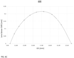
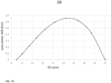
- G1+G2+G3+G4 are moved together as one lens with a small maximum stroke ⁇ d ( ⁇ d ⁇ 0.25mm see FIG. 6C , ⁇ d ⁇ 0.7mm see FIG 7C ) with respect to image sensor 168.
- camera 160 is referred to as a "G24 FCZT camera".
- the G24 FCZT camera may include a G24 optical lens system as shown and described for example with reference to FIGS. 6A-C and FIGS. 7A-C .
- EFL 1 and EFL 2 (EFL Min ⁇ EFL 1 , EFL 2 ⁇ EFL Max ) with respective distances d 1 and d 2 between OPFE 162 and lens 164
- a difference ⁇ d
- between the distances fulfils ⁇ d ⁇ 1mm.
- a small ⁇ d is beneficial for a slim camera module, as it allows using a small OPFE.
- moving lens 164 by ⁇ d with respect to image sensor 168 (and thus moving lens 164 by ⁇ d with respect to OPFE 162 ) is required to focus camera 160 to infinity.
- FIG. 1D shows schematically another embodiment of a FCZT camera disclosed herein and numbered 170 in a first, minimal zoom state having EFL MIN .
- EFL MIN corresponds to a minimal ZF MIN .
- FCZT camera 170 comprises an OPFE 172, a lens 174, an (optional) optical element 176 and an image sensor 178.
- Lens 174 is divided in four lens groups ("G1", “G2", “G3” and "G4"), wherein each lens group may include one or more lens elements.
- Lens elements included in each of G1, G2, G3 and G4 are fixedly coupled to each other. Further, G1 and G3 are fixedly coupled and move together as one group (group "G13" see marked), while G2 and G4 can move independently of the G13 group.
- FIG. 1E shows FCZT camera 170 schematically in a second, maximal zoom state having EFL MAX .
- the transition or switching from EFL MAX to EFL MIN can be performed continuously, i.e. camera 170 can be switched to any other ZF that satisfies ZF MIN ⁇ ZF ⁇ ZF MAX .
- G13 group is moved with a large stroke, (e.g. of 2 mm or more) with respect to G2, G4 and image sensor 178, while G2 and G4 do not move with respect to image sensor 178.
- camera 170 is referred to as a "G13 FCZT camera”.
- G13 FCZT camera may include a G13 optical lens system ( FIGS. 8A-C ).
- G1+G2+G3+G4 can be moved together as one lens with respect to image sensor 178.
- Table 1 shows values and ranges of various parameters of exemplary optical lens systems numbered 600 - 800 and of FCZT camera module 200, which are shown and described next. These parameters include TTL, EFL, BFL, SD, T Lens , ⁇ d, HA, DA, H M , S given in mm, Half-field-of-view ("HFOV”) given in degrees, power sequence, and F/#, N, N Gi given without units. All of these parameters are defined above or below.
- EFL MIN and EFL MAX , TTL MIN and TTL MAX , BFL MIN and BFL MAX , DA MIN and DA MAX , F/# MIN and F/# MAX , T MIN and T MAX and HFOV MIN and HFOV MAX refer respectively to minimum and maximum EFL, TTL, BFL, DA, F/#, T and HFOV that can be achieved in the respective example.
- Columns "MIN” and "MAX” refer respectively to minimum and maximum values in the range of values given in the other columns.
- TTL is given by TTL MIN .
- TTL MAX is given at a particular intermediate EFL state that corresponds to the maximum in the graphs shown in FIG. 6C and FIG. 7C respectively.
- TTL at state EFL MIN is given by TTL MIN
- TTL at state EFL MAX is given by TTL MAX .
- BFL at state EFL MIN is given by BFL MIN
- BFL at state EFL MAX is given by BFL MAX .
- the optical aperture diameter ("DA") of a lens element is given by the larger of the DA values of the front or the rear surface.
- DA at state EFL MIN is given by DA MIN
- DA at state EFL MAX is given by DA MAX .
- the optical aperture height ("HA") of a lens element is given by the larger of the HA values of the front or the rear surface.
- T Lens the lens thickness
- T Lens the lens thickness
- T Lens the lens thickness
- T Lens the lens at state EFL MAX
- T Lens ,MAX T Lens ,MAX
- HFOV MIN is obtained at EFL MAX
- HFOV MAX is obtained at EFL MIN .
- N represents the number of lens elements in a respective lens.
- #N Gi represents the number of lens elements in a respective lens group Gi.
- S is a stroke range that represents the maximum movement of lens groups required for changing a ZF from EFL MIN to EFL MAX or vice versa.
- R (EFL MAX - EFL MIN )/S is a ratio between a ZF range determined by the EFLs in the extreme states and the stroke range S.
- T(G i ,G i+1 ) MIN and T(G i ,G i+1 ) MAX represent respectively a minimum and maximum thickness of lens groups G i and G i+1 .
- a F/# e.g. F/# MAX
- F/# MAX can be increased by further closing an aperture of the lens.
- the same is valid for a ratio F/# MAX /F/# MIN .
- FIG. 2A shows yet another embodiment of a FCZT camera module disclosed herein and numbered 200 in a perspective view.
- FIG. 2B shows camera module 200 in a side view.
- FIG. 2C shows camera module 200 in a first exploded view, and
- FIG. 2D shows camera module 200 in a second exploded view.
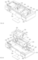
- Camera module 200 comprises an OPFE module 210 with an OPFE 204 (e.g. a prism) that folds the light from OP1 to OP2, and a lens 206 divided into four lens groups G1-G4 included in four lens barrel sections (the barrel sections named after the group number), respectively G1 barrel 212, G2 barrel 214, G3 barrel 216 and G4 barrel 218 (see FIGS 2C-D ).
- Camera module 200 further comprises a housing 202, a top shield 203, a first flex 240 (e.g. a flexible printed circuit board or "flex PCB"), a second flex 245 (e.g. a flex PCB), a sensor module 250 that includes an image sensor 208, and an optional optical element (not shown).
- a first flex 240 e.g. a flexible printed circuit board or "flex PCB”
- second flex 245 e.g. a flex PCB
- sensor module 250 that includes an image sensor 208, and an optional optical
- Housing 202 includes a first yoke 213 and a second yoke 215 (see e.g. FIG. 4B ).
- Flex 240 additionally includes a pitch coil 243 and two yaw coils, a first yaw coil 245 and a second yaw coil 247.
- G1 barrel 212 and G3 barrel 216 are included in a "G13 carrier” 220
- G2 barrel 214 and G4 barrel 218 are included in a "G24 carrier” 230.
- the two barrels included in each of G13 carrier 220 and G24 carrier 230 do not move with respect to each other, but only with respect to the two barrels included in the other of G24 carrier 230 and in G13 carrier 220, as well as with respect to image sensor 208.
- Flex 240 includes a coil 242 and a position sensor 225 ( FIG. 4H ), e.g. a Hall sensor.
- G13 carrier 220 includes an "actuation" magnet 222 and a “position” magnet 224 that form, together with coil 242 and position sensor 225, a "G13 carrier VCM” that actuates G13 carrier 220 with respect to image sensor 208.
- G13 carrier VCM is a closed-loop VCM.
- Actuation magnet 222 and coil 242 form an actuation unit
- position magnet 224 and position sensor 225 form a position sensing unit.
- the actuation of G13 carrier 220 with respect to image sensor 208 may be along the optical axis of lens 206 and over a relatively small stroke of 0.5mm - 5mm. In the example shown, the actuation of G13 carrier 220 is over a stroke of about 1.7mm.
- Flex 245 includes a coil assembly ("CA") 246 and a Hall sensor 248.
- CA 246 may include 2 or more coils.
- G24 carrier 230 includes a magnet assembly ("MA") of three or more magnets which forms, together with CA 246 and Hall sensor 248, a "G24 carrier VCM” that actuates G24 carrier 230 with respect to image sensor 208.
- the G24 carrier VCM may additionally include a position sensing unit for controlling an actuation of G24 carrier 230 with respect to image sensor 208.
- G24 carrier VCM" is a "large stroke” VCM for performing large stroke movements as described above or below, as e.g. described in PCT/IB2021/056693.
- G24 carrier VCM is a closed-loop VCM.
- the actuation of G24 carrier 230 with respect to image sensor 208 may be along the optical axis of lens 206 and over a relatively large stroke of 2.0mm - 15mm. In the example shown, the actuation of G24 carrier 230 is over a stroke of about 6.2mm. Because the G24 carrier moves along a relatively large stroke and the G13 carrier moves along a relatively small stroke, camera module 200 is referred to as a "G24 FCZT camera module".
- a G24 FCZT camera module may include a G24 FCZT camera ( FIGS. 1B-C ).
- Camera module 200 has a module height H M and includes a camera aperture 209 with an aperture height H A .
- Module height H M and aperture height H A are both measured along the Y-axis in the coordinate system shown in FIG. 2B (i.e., along OP1).
- Aperture height H A is determined by the optical height ("H L " - see FIG. 6A , FIG. 9) of the lens element that determines an aperture stop of camera 200.
- H M may be 6.2mm and H A may be 5.0mm.
- Module length L M may be about 40mm, in general 25mm-60mm.
- Lens 206 may be a "cut” (or “D-cut”) lens as known in the art and shown in FIG. 2E , which shows a cut lens 260.
- Cut lens 260 is cut along an axis parallel to the x axis at the sides marked 262 and 264. At the sides marked 266 and 268, lens 260 is not cut. Therefore, lens 260 has an optical lens width W L (measured along the x axis) which is larger than its optical lens height H L (measured along the Y-axis).
- Using a cut lens such as lens 260 is beneficial in folded cameras, as it supports slim camera height while still providing a relatively large aperture area (AA) of AA > H L 2 and AA > (H L /2) 2 ⁇ .
- AA aperture area
- G4 included in G4 barrel 218 may be cut, meaning that W A > H A is fulfilled, as shown in FIG. 5A .
- a cut lens has one or more lens elements Li that are cut, i.e. that have an optical width ("W Li ”) measured along a first axis perpendicular to the lens optical axis that is larger than an optical height ("H Li ”) measured along a second axis perpendicular to the lens optical axis, i.e. W Li > H Li .
- W Li optical width
- H Li optical height
- a D-cut ratio of a cut lens may be 0% - 50%, meaning that W Li may be larger than H Li by 0% - 50%, i.e..
- the cutting may reduce module height H M of the camera module above.
- FIG. 3A shows camera module 200 from FIGS. 2A-2D in a perspective view and without top shield 203.
- FIG. 3B shows camera module 200 without top shield 203 from FIG. 3A in an exploded view.
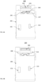
- FIG. 4A shows camera module 200 in a bottom view and with flex 240 partly removed for exposing pitch coil 243, pitch position sensor 302 as well as two yaw coils 245 and 247 and yaw position sensor 304. Yoke 213 and yoke 215 are visible.
- FIG. 4B shows camera module 200 in a bottom view and with flex 240 as well as pitch coil 243, pitch position sensor 302, yaw coils 245 and 247 and yaw position sensor 304 partly removed for exposing pitch magnet 306 as well as two yaw magnets 308 and 312.
- Pitch coil 243, pitch position sensor 302 and pitch magnet 306 form together a, "first OIS VCM" for performing optical image stabilization (OIS) around a first OIS rotation axis.
- Yaw coils 245 and 247, yaw position sensor 304 and yaw magnets 308 and 312 form together a "second OIS VCM" for performing OIS around a second OIS rotation axis.
- First OIS rotation axis is perpendicular to both OP1 and OP2, second OIS rotation axis is parallel to OP1.
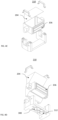
- FIG. 4C shows OPFE module 210 in a perspective top view.
- FIG. 4D shows OPFE module 210 in a perspective bottom view.
- FIG. 4E shows G13 carrier 220 in a perspective bottom view.
- FIG. 4F shows G13 carrier 220 in a bottom view.
- G13 carrier 220 includes a preload magnet 229 which is attracted to yoke 215.
- G13 carrier 220 additionally includes two grooved rails 228-1 and 228-2 and two flat rails 226-1 and 226-2.
- FIG. 4G shows G24 carrier 230 in a perspective top view.
- G24 carrier 230 includes a preload magnet 232 which connects to yoke 213.
- G24 carrier 230 additionally includes two grooved rails 234-1 and 234-2 and two grooved rails 236-1 and 236-2 and magnet assembly 402.
- Grooved rails 234-1, 234-2, 236-1 and 236-2 in G24 carrier 230 and grooved rails 226-1 and 226-2 and flat rails 228-1 and 228-2 in G13 carrier 220 include balls, so that they form ball-groove mechanisms that allow G13 carrier 220 to move on top of and relative to G24 carrier 230 and relative to image sensor 208 by means of G13 carrier VCM.
- G24 carrier 230 moves relative to G13 carrier 220 and relative to image sensor 208 by means of G24 carrier VCM.
- FIG. 4H shows position magnet 224 included in G13 carrier 220 in a perspective view.
- Position sensor 225 included in flex 240 is also shown. Together, position magnet 224 and position sensor 225 form a position sensing unit 410 that controls the actuation of G13 carrier 220.
- Position sensing unit 410 is a large stroke position sensing unit as known in the art and e.g. described in PCT/IB2021/056693.
- FIG. 5A shows components of FCZT camera module 200 in a minimum zoom state in a perspective view.
- EFL MIN may be ⁇ 9mm and a minimal F/# may be F/# MIN ⁇ 2.3.
- G4 included in G4 barrel 218 may be a cut (or D-cut) lens as known in the art, i.e. G4 may have an optical lens width (W L ) and an optical lens height (H L ) that fulfill W L >H L . In other examples, further lens groups or all lens groups may be D-cut.
- FIG. 5B shows components of FCZT camera module 200 in an intermediate zoom state in a perspective view.
- an EFL INT may be 16mm.
- FIG. 5C shows components of FCZT camera module 200 in a maximum zoom state in a perspective view.
- an EFL MAX may be 24mm-30mm and a maximal F/# may be F/# MAX ⁇ 6.
- a G13 FCZT camera module including a G13 FCZT camera ( FIGS. 1D-E )
- the G13 carrier moves along a relatively large stroke and the G24 carrier moves along a relatively small stroke.
- a G13 FCZT camera module may be realized by exchanging G24 carrier VCM and G13 carrier VCM, i.e. the large stroke G24 carrier VCM may be used to actuate a G13 carrier such as G13 carrier 220 over a relatively large stroke, and the G13 carrier VCM may be used to actuate a G24 carrier such as G24 carrier 230 over a relatively small stroke.
- a yoke that attracts G24 carrier 230 such as yoke 213 and a yoke that attracts G13 carrier 220 such as yoke 215 respectively may be located at positions different than the ones shown for G24 FCZT camera module 200.
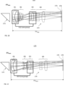
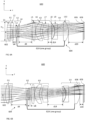
- FIGS. 6A-6B show a G24 optical lens system disclosed herein and numbered 600 which may be included into a G24 FCZT camera like camera 160.
- Optical lens system 600 comprises a lens 604 having a lens optical axis 602, an (optional) optical element 606 and an image sensor 608.
- System 600 is shown with ray tracing.
- Optical element 606 may be for example an infra-red (IR) filter, and/or a glass image sensor dust cover.
- lens 604 is divided into four lens groups G1, G2, G3 and G4.
- G1 includes (in order from an object to an image side of optical system 600 ) lens elements L1-L2, G2 includes L3-L4, G3 includes L5-L7 and G4 includes L8-L10.
- the lens elements included in each lens group are fixedly coupled to each other.
- Lens 604 includes a plurality of N lens elements L i .
- N 10.
- L 1 is the lens element closest to the object side
- L N is the lens element closest to the image side, i.e. the side where the image sensor is located. This order holds for all lenses and lens elements disclosed herein.
- Each lens element L i comprises a respective front surface S 2i-1 (the index “21-1” being the number of the front surface) and a respective rear surface S 2i (the index “21” being the number of the rear surface), where “i” is an integer between 1 and N.
- This numbering convention is used throughout the description. Alternatively, as done throughout this description, lens surfaces are marked as “S k ", with k running from 1 to 2N.
- G24 optical lens system 600 as well as all other optical lens systems disclosed herein are shown without D-cut.
- Maximizing R is desired, as, (1) for a given ZF range, determined by EFL MAX - EFL MIN , a smaller stroke S is required for switching between EFL MAX and EFL MIN , or, (2) for a given stroke S, a larger ZF range, determined by EFL MAX - EFL MIN , is provided.
- G1+G2+G3+G4 together must be moved as one lens with respect to image sensor 608 as specified in FIG. 6C.
- FIG. 6C gives the values for ⁇ d, as defined in FIGS. 1B-1C . As visible, ⁇ d ⁇ 0.25mm. A small ⁇ d is beneficial.
- L1, L2 are uniformly close to each other.
- a lens pair L i , L i+1 is "uniformly close to each other", if for all values between OA and DA/2 (i.e. a margin of L i or L i+1 ) along the y-axis, the lens pair fulfils all of these three criteria:
- Lens pair L1, L2 is a "doublet lens", what is beneficial for achieving low chromatic aberration.
- a lens pair L i , L i+1 is defined a “doublet lens” if it fulfils all of these three criteria:
- a lens pair L i , L i+1 is defined an "inverted doublet lens", if it fulfils all of these three criteria:
- Table 5 shows all doublet lenses and inverted doublet lenses that are included in the optical lens system examples 600 - 800 disclosed herein as well as values thereof (Max-d, ⁇ , ⁇ given in mm, n and v given without units). "Type” specifies whether the lens pair is a doublet lens ("D") or an inverted doublet lens (“ID").
- FIGS. 7A-7B show another G24 optical lens system 700 disclosed herein that may be included into a G24 FCZT camera like camera 160.
- Optical lens system 700 comprises a lens 704 having a lens optical axis 702, an (optional) optical element 706 and an image sensor 708.
- System 700 is shown with ray tracing.
- Lens 704 is divided into G1, G2, G3 and G4.
- G1 includes L1-L2
- G2 includes L3-L4
- G3 includes L5-L7
- G4 includes L8-L10.
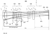
- FIGS. 8A-8C show a G13 optical lens system 800 disclosed herein that may be included into a G13 FCZT camera like camera 170.
- Optical lens system 800 comprises a lens 804 having a lens optical axis 802, an (optional) optical element 806 and an image sensor 808.
- System 800 is shown with ray tracing.
- Lens 804 is divided into G1, G2, G3 and G4.
- G1 includes L1-L2
- G2 includes L3-L5
- G3 includes L6-L8
- G4 includes L9-L10.
- the term “substantially” is used herein to imply the possibility of variations in values within an acceptable range. According to one example, the term “substantially” used herein should be interpreted to imply possible variation of up to 10% over or under any specified value. According to another example, the term “substantially” used herein should be interpreted to imply possible variation of up to 5% over or under any specified value. According to a further example, the term “substantially” used herein should be interpreted to imply possible variation of up to 2.5% over or under any specified value.
Landscapes
- Physics & Mathematics (AREA)
- General Physics & Mathematics (AREA)
- Engineering & Computer Science (AREA)
- Optics & Photonics (AREA)
- Multimedia (AREA)
- Signal Processing (AREA)
- Human Computer Interaction (AREA)
- General Engineering & Computer Science (AREA)
- Lenses (AREA)
- Studio Devices (AREA)
Description
- Embodiments (examples) disclosed herein relate in general to digital cameras, and more particularly, to multi-aperture zoom digital cameras with a folded continuous zoom lens for use in handheld electronic mobile devices such as smartphones.
- The following symbols and abbreviations are used, all of terms known in the art:
Total track length (TTL): the maximal distance, measured along an axis parallel to the optical axis of a lens, between a point of the front surface S1 of a first lens element L1 and an image sensor, when the system is focused to an infinity object distance. - Back focal length (BFL): the minimal distance, measured along an axis parallel to the optical axis of a lens, between a point of the rear surface S2N of the last lens element LN and an image sensor, when the system is focused to an infinity object distance.
- Effective focal length (EFL): in a lens (or an assembly of lens elements L1 to LN), the distance between a rear principal point P' and a rear focal point F' of the lens.
- F number (F/#): the ratio of the EFL to an entrance pupil diameter.
- Multi-aperture cameras (or "multi-cameras", of which a "dual-camera" having two cameras is an example) are now standard for handheld electronic mobile devices (or simply "mobile devices", for example smartphones, tablets, etc.). A multi-camera usually comprises a wide field-of-view FOV camera ("Wide" or "W" camera with FOVw), and at least one additional camera with a narrower (than FOVw) field-of-view (Telephoto, "Tele" or "T" camera, also referred to as "TC", with FOVT). In general, the spatial resolution of the TC is constant (or "fixed") and may be for example 3, 5, or 10 times higher than the spatial resolution of the W camera. This is referred to as the TC having a fixed "zoom factor" (ZF) of, respectively, 3, 5, or 10.
- As an example, consider a dual-camera having a W camera and a TC with ZF of 5. When zooming onto a scene, one may in general use W camera image data, which is digitally zoomed up to a ZF of 5. For a ZF ≥ 5, one may use TC image data, digitally zoomed for ZF > 5. In some scenes, a high ZF is desired for capturing scene segments with high spatial resolution. In other scenes, a high ZF is undesired, as only (digitally zoomed) W camera image data may be available. This shows the trade-off between the applicability range of the TC on the one hand (which is larger for TCs with smaller ZF) and the TC's zoom capability on the other hand (which is larger for TCs with larger ZF). In general, both large applicability range and large zoom capability are beneficial. This cannot be achieved in known TCs having a fixed ZF.
- For a given image sensor included in a TC, the TC's ZF is determined solely by its EFL. A TC that can switch continuously between two extreme (minimal and maximal) EFLs, EFLMIN and EFLMAX, for providing any ZF between minimal and maximal ZFs ZFMIN and ZFMAX, is described for example in co-owned international patent application
PCT/IB2021/061078 . - There is need for, and it would be beneficial to have a Tele camera that can provide all ZFs between ZFMIN and ZFMAX wherein ZFMAX ≥2x ZFMIN, continuously and in a slim camera module form factor having large aperture heights for a given camera module's height and by requiring relatively small lens stroke ranges for switching between ZFMIN and ZFMAX.
-
US 2006/262420 A1 relates to a lens unit incorporating, for example, a variable-magnification optical system, and to an image-sensing apparatus incorporating such a lens unit. 1 -
US 2021/026117 A1 relates generally to camera systems, and more specifically to small form factor camera and lens systems. - Itay Yedid's paper "THE EVOLUTION OF ZOOM CAMERA TECHNOLOGIES IN SMARTPHONES" (published on August 1, 2017) covers the entire evolution of zoom cameras in smartphones, from early days of the Samsung Galaxy K-zoom, through the latest iPhones and the Samsung Note8, to the future of folded zoom cameras. It also explains some of the mobile photography fundamentals and how vendors strike a fine balance between them.
-
US 2009/161228 A1 relates to a refracting zoom lens system having a shake correction function. - According to
claim 1 of the present invention, there is provided a camera, comprising: an OPFE for a folding a first optical path OP1 to second optical path OP2; a lens including N lens elements, the lens being divided into four lens groups arranged along a lens optical axis and marked, in order from an object side of the lens to an image side of the lens, G1, G2, G3 and G4; and an image sensor, the camera is a folded Tele camera, the lens elements of a lens group do not move with respect to each other, G1 and G3 do not move with respect to each other, G2 and G4 do not move with respect to each other, the Tele camera is configured to change a zoom factor (ZF) continuously between ZFMIN corresponding to EFLMIN and ZFMAX corresponding to EFLMAX by moving G1 and G3 together relative to the image sensor and by moving G2 and G4 together relative to the image sensor, wherein ZFMAX/ZFMIN ≥ 2, wherein switching from EFLMIN to EFLMAX or vice versa requires a lens stroke range S, and wherein a ratio R given by R = (EFLMAX - EFLMIN)/S fulfils R>2. - In some examples, R>3. In some examples, R>5.
- In some examples, ZFMAX/ZFMIN ≥2.5. In some examples, ZFMAX/ZFMIN ≥2.75.
- In some examples, the configuration to change the ZF continuously includes a configuration to move G1 and G3 together relative to the image sensor over a small range larger than 0.1mm and smaller than 5mm and to move G2 and G4 together relative to the image sensor over a large range larger than 2mm and smaller than 15mm.
- In some examples, the configuration to change the ZF continuously includes a configuration to move G1 and G3 together relative to the image sensor over a small range larger than 0.2mm and smaller than 2.5mm, and to move G2 and G4 together relative to the image sensor over a large range larger than 4mm and smaller than 10mm.
- In some examples, the configuration to change the ZF continuously includes a configuration to move G2 and G4 together relative to the image sensor over a small range larger than 0.1mm and smaller than 5mm, and to move G1 and G3 together relative to the image sensor over a large range larger than 2mm and smaller than 15mm.
- In some examples, the configuration to change the ZF continuously includes a configuration to move G2 and G4 together relative to the image sensor over a small range larger than 0.2mm and smaller than 2.5mm, and to move the G1 and G3 together relative to the image sensor over a large range larger than 4mm and smaller than 10mm.
- In some examples, G1 and G3 are included in a single G13 carrier and G2 and G4 are included in a single G24 carrier.
- In some examples, both the G24 carrier and the G13 carrier include rails for defining a position of the G13 carrier relative to the G24 carrier.
- In some examples, a maximum stroke range of the G13 carrier is S13, a maximum stroke range of the G24 carrier is S24, and a ratio S24/S13>7.5. In some examples, S24/S13>12.5.
- In some examples, the G24 and G13 carriers are movable by, respectively, G24 and G13 actuators. In some examples, one of the G24 actuator or the G13 actuator includes three or more magnets.
- In some examples, the lens includes N=10 lens elements.
- In some examples, a power sequence of lens groups G1-G4 is positive-negative-positive-positive.
- In some examples, G1 includes two lens elements with a positive-negative power sequence, G2 includes two lens elements with a negative-negative power sequence, G3 includes three lens elements with a positive-positive-positive power sequence, and G4 includes three lens elements with a positive-negative-positive power sequence.
- In some examples, G1 includes two lens elements with a positive-negative power sequence, G2 includes two lens elements with a negative-positive power sequence, G3 includes three lens elements with a positive-negative-positive power sequence, and G4 includes three lens elements with a positive-negative-positive power sequence.
- In some examples, G1 includes two lens elements with a negative-positive power sequence, G2 includes three lens elements with a positive-negative-negative power sequence, G3 includes three lens elements with a positive-negative-negative power sequence, and G4 includes two lens elements with a negative-positive power sequence.
- In some examples, the camera has a F number F/#, the F/# at ZFMIN is F/#MIN, the F/# at ZFMAX is F/#MAX, and EFLMAX/EFLMIN > F/#MAX/F/#MIN. In some examples, EFLMAX/EFLMIN > F/#MAX/F/#MIN + 0.5.
- In some examples, a magnitude of an EFL of G2 |EFLG2| varies less than 10% from a magnitude of an EFL of G3 |EFLG3|, and |EFLG2|, |EFLG3| < EFLMIN.
- In some examples, lens groups G1 and G2 include 2 lens elements, and lens group G3 and G4 include 3 lens elements.
- In some examples, the larger of a thickness TG2 of G2 and of a thickness TG1 of G1 is T(G1,G2)MAX, the smaller of TG2 and TG1 is T(G1,G2)MIN, and T(G1,G2)MIN/T(G1,G2)MAX <0.8. In some examples, 0.75<T(G1,G2)MIN/T(G1,G2)MAX <1.0.
- In some examples, a ratio of a thickness TG4 of G4 and a thickness TG3 of G3 fulfill 0.9 <TG4/TG3<1.1.
- In some examples, the larger of TG3 and TG4 is T(G3,G4)MAX, the smaller of TG3 and TG4 is T(G3,G4)MIN, and T(G1,G2)MAX/T(G3,G4)MIN <0.5. In some examples, 0.5<T(G3,G4)MIN/T(G3,G4)MAX <0.75. In some examples, 0.9<T(G1,G2)MAX/T(G3,G4)MIN <1.1.
- In some examples, lens groups G1 and G4 include 2 lens elements, and lens groups G2 and G3 include 3 lens elements.
- In some examples, the camera includes an aperture stop, and the aperture stop is located at a front surface of a first lens element of G2. In some examples, the aperture stop is located at a rear surface of a second lens element of G2. In some examples, aperture stop is located at the front surface of the first lens element of G3.
- In some examples, an EFL of G1 (EFLG1) varies less than 50% from an EFL of G4 (EFLG4), and both EFLG1 and EFLG4 vary by less than 20% from (EFLMAX+EFLMIN)/2. In some examples, EFLG1 varies less than 50% from EFLG4 and both EFLG1 and EFLG4 vary by less than 20% from (EFLMAX+EFLMIN)/2. In some examples, EFLG4> 10xEFLMAX.
- In some examples, EFLG1<0.15xEFLG4, and both EFLG1 and EFLG4 vary by less than 20% from (EFLMAX+EFLMIN)/2. In some examples, EFLG4> 10xEFLMIN.
- In some examples, G1 and G3 have each at least two lens elements, and the first two lens elements in each of G1 and G3 are separated from each other on the lens optical axis by <0.75mm. In some examples, G1 and G3 have each at least two lens elements, and the first two lens elements in each of G1 and G3 are separated from each other on the lens optical axis by <0.1xEFLMIN.
- In some examples, first two lens elements in G2 and in G4 are separated from each other at margins of each lens element by <0.1mm. In some examples, first two lens elements in G2 and in G4 are separated from each other at margins of each lens element by <0.01xEFLMIN.
- In some examples, the N lens elements include a first lens element L1, a second lens element L2, an eighth lens element L8 and a ninth lens element L9, and L1 and L2 and L8 and L9 form respective doublet lenses.
- In some examples, first two lens elements in G2 and in G4 are separated from each other at margins of each lens element by <0.1mm. In some examples, first two lens elements in G2 and in G4 are separated from each other at margins of each lens element by <0.01xEFLMIN.
- In some examples, the N lens elements include a first lens element L1, a second lens element L2, a third lens element L3, a fourth lens element L4, a sixth lens element L6, a seventh lens element L7, an eight lens element L8 and a ninth lens element L9, L1 and L2, L3 and L4, and L8 and L9 form respective doublet lenses, and L6 and L7 form an inverted doublet lens.
- In some examples, a maximum distance between lens elements of the moving groups G1 and G3 is smaller than 0. 1xEFLMIN.
- In some examples, the N lens elements include a first lens element L1, a second lens element L2, a third lens element L3, a fourth lens element L4, an seventh lens element L7 and an eighth lens element L8, L1 and L2, L3 and L4, form respective inverted doublet lenses, and L7 and L8 form a doublet lens.
- In some examples, a difference between distances of the OPFE from the front surface of the first lens element lens measured along an axis parallel to the lens optical axis for all ZFs is marked Δd, and a ratio of Δd and a lens thickness TLens fulfils Δd/TLens < 0.25 when Δd<4mm. In some examples, Δd/TLens < 0.05 for Δd<1mm.
- In some examples, the camera has an aperture diameter DAMIN at EFLMIN and a minimum F number F/#MIN = EFLMIN/DAMIN, and F/#MIN is <4. In some examples, F/#MIN is < 3. In some examples, F/#MIN is < 2.5.
- In some examples, the camera has an aperture diameter DAMAX at EFLMAX, and a maximum F number F/#MAX = EFLMAX/DAMAX, and 4.4<F/#MAX < 6.
- In some examples, DAMIN/DAMAX>0.4. In some examples, DAMIN/DAMAX>0.5. In some examples, DAMIN/DAMAX >0.75. In some examples, 5mm<DAMAX <7mm.
- In some examples, F/#MIN = EFLMIN/DAMIN, F/#MAX = EFLMAX/DAMAX, and F/#MAX/ F/#MIN<1.3 - 3.
- In some examples, the lens has a maximum total track length TTLMAX, and TTLMAX/EFLMAX <1.2. In some examples, TTLMAX/EFLMAX <1.1.
- In some examples, the camera is configured to be focused by moving lens groups G1+G2+G3+G4 together as one lens.
- In some examples, the camera is included in a camera module having a module height HM, the lens has a lens aperture height HA, both HM and HA are measured along an axis parallel to OP1, HM = 5mm - 15mm, HA = 3mm - 10mm, and HM <HA+3mm. In some examples, HM <HA+2mm.
- In some examples, the OPFE is configured to be rotated for optical image stabilization (OIS) along two rotation axes, a first rotation axis parallel to OP1 and a second rotation axis perpendicular to both OP1 and OP2.
- In some examples, the OPFE is a prism.
- In some examples, the prism is a cut prism with a prism optical height HP measured along an axis parallel to OP1 and with a prism optical width WP measured along an axis perpendicular to both OP1 and OP2, and WP is larger than HP by between 5% and 30%.
- In some examples, the lens is a cut lens with a cut lens aperture height HA measured along an axis parallel to OP1 and with a lens aperture width WA measured along an axis perpendicular to both OP1 and OP2, and WA is larger than HA by between 5% and 50%.
- In some examples, EFLMAX is between 24mm and 30mm.
- In some examples, EFLMIN ≥ 9mm.
- In some examples, the folded Tele camera is included in a dual-camera along with a Wide camera having a field-of-view larger than the folded Tele camera. In some examples, there is provided a smartphone comprising a dual-camera as above.
- In some examples, there is provided a smartphone comprising any of the cameras above or below.
- Non-limiting examples of embodiments disclosed herein are described below with reference to figures attached hereto that are listed following this paragraph. The drawings and descriptions are meant to illuminate and clarify embodiments disclosed herein and should not be considered limiting in any way. Like elements in different drawings may be indicated by like numerals. Elements in the drawings are not necessarily drawn to scale. In the drawings:
-
FIG. 1A illustrates a dual-camera that comprises a known folded continuous zoom T camera (or "FCZT camera") as disclosed herein together with a W camera; -
FIG. 1B shows schematically an embodiment of a G24 FCZT camera disclosed herein in a first, minimal zoom state with ZFMIN and EFLMIN; -
FIG. 1C shows the FCZT camera ofFIGS. 1A and1B schematically in a second, maximal zoom state with ZFMAX and EFLMAX; -
FIG. 1D shows schematically an embodiment of a G13 FCZT camera disclosed herein and in a first, minimal zoom state with ZFMIN and EFLMIN; -
FIG. 1E shows the FCZT camera ofFIG. 1D schematically in a second, maximal zoom state with ZFMAX and EFLMAX; -
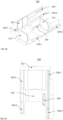
FIG. 2A shows an embodiment of a G24 FCZT camera module disclosed herein in a perspective view; -
FIG. 2B shows the camera module ofFIG. 2A in a side view; -
FIG. 2C shows the camera module ofFIG. 2A in a first exploded view; -
FIG. 2D shows the camera module ofFIG. 2A in a second exploded view; -
FIG. 2E shows an example a cut lens; -
FIG. 2F shows an example of a cut prism; -
FIG. 3A shows the camera module ofFIG. 2A in a perspective view and without a top shield; -
FIG. 3B shows the camera module ofFIG. 2A without the top shield fromFIG. 3A in an exploded view; -
FIG. 4A shows the camera module ofFIG. 2A-2D in a bottom view and with a flex partly removed for exposing a pitch coil, a pitch position sensor, two yaw coils and a yaw position sensor; -
FIG. 4B shows the camera module ofFIG. 2A-2D in a bottom view with some of the elements shown inFIG. 4A removed; -
FIG. 4C shows an OPFE module in the camera module ofFIG. 2A-2D in a perspective top view; -
FIG. 4D shows the OPFE module ofFIG. 4C in a perspective bottom view; -
FIG. 4E shows a G13 carrier in the camera module ofFIG. 2A-2D in a perspective bottom view; -
FIG. 4F shows the G13 carrier ofFIG. 4E in a bottom view; -
FIG. 4G shows a G24 carrier in the camera module ofFIG. 2A-2D in a perspective top view; -
FIG. 4H shows a position magnet included in the G13 carrier and a position sensor included in the flex in a perspective view; -
FIG. 5A shows components of the FCZT camera module ofFIGS. 2A-2D in a minimum zoom state in a perspective view; -
FIG. 5B shows components of the FCZT camera module ofFIGS. 2A-2D in an intermediate zoom state in a perspective view; -
FIG. 5C shows components of the FCZT camera module ofFIGS. 2A-2D in a maximum zoom state in a perspective view; -
FIG. 6A shows a first example of an optical lens system disclosed herein in a first, minimal zoom state having an EFLMIN=9.6mm; -
FIG. 6B shows the optical lens system ofFIG. 6A in a second, maximum zoom state having an EFLMAX=24.0mm; -
FIG. 6C gives the values for Δd for the optical lens system ofFIGS. 6A-B , as defined inFIGS. 1B-1C ; -
FIG. 7A shows a second example of an optical lens system disclosed herein in a minimal zoom state having an EFLMIN=9.96mm; -
FIG. 7B shows the optical lens system ofFIG. 7A in a maximum zoom state having an EFLMAX=27.0mm; -
FIG. 7C gives the values for Δd for the optical lens system ofFIGS. 7A-B , as defined inFIGS. 1B-1C ; -
FIG. 8A shows a third example of an optical lens system disclosed herein in a minimal zoom state having an EFLMIN=10mm; -
FIG. 8B shows the optical lens system ofFIG. 8A in an intermediate zoom state having an EFLMID=20mm; -
FIG. 8C shows the optical lens system ofFIG. 8A in a maximum zoom state having an EFLMAX=30mm. -
FIG. 1A illustrates a dual-camera 150 that comprises a folded continuous zoom T camera (or "FCZT camera") 100 as disclosed herein together with aW camera 130.T camera 100 comprises an optical path folding element (OPFE) 102 e.g. a prism or mirror, alens 110 with a plurality of lens elements (not visible in this representation) having a lensoptical axis 108 and animage sensor 106. OPFE folds an optical path from a first optical path 112 ("OP1") to a second optical path 114 ("OP2").W camera 130 comprises alens 134 with anoptical axis 136 and animage sensor 138. -
FIG. 1B shows schematically an embodiment of a FCZT camera disclosed herein and numbered 160 in a first, minimal zoom state (with a minimal zoom factor ZFMIN) having a minimal EFL = EFLMIN. EFLMIN corresponds to a minimal ZFMIN.FCZT camera 160 comprises anOPFE 162, alens 164, an (optional)optical element 166 and animage sensor 168.Camera 160 is shown with ray tracing.Optical element 166 may be for example an infra-red (IR) filter, and/or a glass image sensor dust cover.Lens 164 is divided in four lens groups ("G1", "G2", "G3" and "G4"), wherein each lens group may include one or more lens elements. Lens elements included in each of G1, G2, G3 and G4 are fixedly coupled to each other, meaning that the lens elements included in each of G1, G2, G3 and G4 can move with respect to the lens elements included in any other lens group and with respect to other components included in camera 160 (such as image sensor 168), but not with respect to each other. Further, G2 and G4 are fixedly coupled and move together as one group (group "G24" see marked). The G24 group is moved with a large stroke, G1+G2+G3+G4 are moved together as one lens with a small stroke, while G1 and G3 can move together independently of the G24 group. -
FIG. 1C showsFCZT camera 160 schematically in a second, maximal zoom state (with a maximal zoom factor ZFMAX) having a maximal EFL=EFLMAX. The transition or switching from EFLMAX to EFLMIN can be performed continuously, i.e.camera 160 can be switched to any other ZF that satisfies ZFMIN ≤ ZF ≤ ZFMAX (or EFLMIN≤ EFL ≤ EFLMAX). - This functionality is known in zoom camera lenses that are used for example in relatively large handheld camera devices such as digital single-lens reflex (DSLR) cameras.
Camera 160 can provide this known functionality while having size dimensions that allow it to be integrated in a camera module such as a G24 FCZT camera module 200 (FIG. 2 ), which fits the size constraints of handheld (portable) electronic mobile devices such as smartphones. To clarify, all camera modules and optical lens systems disclosed herein may beneficially be included or incorporated in smartphones. - For changing ZF, the G24 group is moved with a large stroke, (e.g. of 2 mm or more) with respect to G1, G3 and
image sensor 168. In addition and dependent on the particular desired EFL, G1+G2+G3+G4 are moved together as one lens with a small maximum stroke Δd (Δd≤0.25mm seeFIG. 6C , Δd≤0.7mm seeFIG 7C ) with respect toimage sensor 168. Because of this movement required for ZF change,camera 160 is referred to as a "G24 FCZT camera". The G24 FCZT camera may include a G24 optical lens system as shown and described for example with reference toFIGS. 6A-C andFIGS. 7A-C . - For situations with
camera 160 focused to infinity, a distance "d" betweenOPFE 162 andlens 164, measured fromOPFE 162 to the first surface of the first lens element in G1 along an axis parallel to the lens optical axis, shown (inFIG. 1B ) in the EFLMin state (dMin) and (inFIG. 1C ) in the EFLMax state (dMin), changes slighty for intermediate states EFLMin≤EFL≤ EFLMax as detailed inFIG. 6C andFIG. 7C . For any arbitrary pair of EFL states EFL1 and EFL2 (EFLMin≤ EFL1, EFL2 ≤EFLMax) with respective distances d1 and d2 betweenOPFE 162 andlens 164, a difference Δd=|d1-d2| between the distances fulfils Δd< 1mm. A small Δd is beneficial for a slim camera module, as it allows using a small OPFE. After a ZF change, movinglens 164 by Δd with respect to image sensor 168 (and thus movinglens 164 by Δd with respect to OPFE 162) is required to focuscamera 160 to infinity. -
FIG. 1D shows schematically another embodiment of a FCZT camera disclosed herein and numbered 170 in a first, minimal zoom state having EFLMIN. EFLMIN corresponds to a minimal ZFMIN.FCZT camera 170 comprises anOPFE 172, alens 174, an (optional)optical element 176 and animage sensor 178.Lens 174 is divided in four lens groups ("G1", "G2", "G3" and "G4"), wherein each lens group may include one or more lens elements. Lens elements included in each of G1, G2, G3 and G4 are fixedly coupled to each other. Further, G1 and G3 are fixedly coupled and move together as one group (group "G13" see marked), while G2 and G4 can move independently of the G13 group. -
FIG. 1E showsFCZT camera 170 schematically in a second, maximal zoom state having EFLMAX. As incamera 160, the transition or switching from EFLMAX to EFLMIN can be performed continuously, i.e.camera 170 can be switched to any other ZF that satisfies ZFMIN ≤ ZF ≤ ZFMAX. - For changing ZF, G13 group is moved with a large stroke, (e.g. of 2 mm or more) with respect to G2, G4 and
image sensor 178, while G2 and G4 do not move with respect toimage sensor 178. As of this movement required for ZF change,camera 170 is referred to as a "G13 FCZT camera". G13 FCZT camera may include a G13 optical lens system (FIGS. 8A-C ). For focusing, G1+G2+G3+G4 can be moved together as one lens with respect toimage sensor 178. - Table 1 shows values and ranges of various parameters of exemplary optical lens systems numbered 600 - 800 and of
FCZT camera module 200, which are shown and described next. These parameters include TTL, EFL, BFL, SD, TLens, Δd, HA, DA, HM, S given in mm, Half-field-of-view ("HFOV") given in degrees, power sequence, and F/#, N, NGi given without units. All of these parameters are defined above or below. - EFLMIN and EFLMAX, TTLMIN and TTLMAX, BFLMIN and BFLMAX, DAMIN and DAMAX, F/#MIN and F/#MAX, TMIN and TMAX and HFOVMIN and HFOVMAX refer respectively to minimum and maximum EFL, TTL, BFL, DA, F/#, T and HFOV that can be achieved in the respective example. Columns "MIN" and "MAX" refer respectively to minimum and maximum values in the range of values given in the other columns.
- In optical lens system examples 600 and 700, at both state EFLMIN and state EFLMAX TTL is given by TTLMIN. TTLMAX is given at a particular intermediate EFL state that corresponds to the maximum in the graphs shown in
FIG. 6C andFIG. 7C respectively. In optical lens system example 800, TTL at state EFLMIN is given by TTLMIN, and TTL at state EFLMAX is given by TTLMAX. - In optical lens system examples 600 and 700, BFL at state EFLMIN is given by BFLMIN, and BFL at state EFLMAX is given by BFLMAX.
- The optical aperture diameter ("DA") of a lens element is given by the larger of the DA values of the front or the rear surface. In all optical lens system examples 600 - 800, DA at state EFLMIN is given by DAMIN, and DA at state EFLMAX is given by DAMAX.
- The optical aperture height ("HA") of a lens element is given by the larger of the HA values of the front or the rear surface.
- All values of optical lens system examples 600 - 800 are given for lenses without D-cut, so that DAMIN=HAMIN and DAMAX=HAMAX.
- In all optical lens system examples 600 - 800, the lens thickness ("TLens") at state EFLMIN is given by TLens ,MIN, and TLens at state EFLMAX is given by TLens ,MAX. HFOVMIN is obtained at EFLMAX and HFOVMAX is obtained at EFLMIN.
- "N" represents the number of lens elements in a respective lens. "#NGi" represents the number of lens elements in a respective lens group Gi.
- "SD" represents the sensor diagonal.
- "S" is a stroke range that represents the maximum movement of lens groups required for changing a ZF from EFLMIN to EFLMAX or vice versa.
- R = (EFLMAX - EFLMIN)/S is a ratio between a ZF range determined by the EFLs in the extreme states and the stroke range S.
- T(Gi,Gi+1)MIN and T(Gi,Gi+1)MAX represent respectively a minimum and maximum thickness of lens groups Gi and Gi+1.
- It is noted that a F/#, e.g. F/#MAX, can be increased by further closing an aperture of the lens. The same is valid for a ratio F/#MAX/F/#MIN.
- For lens power sequences, "+" indicates a positive lens power and "-" indicates a negative lens power.
Table 1 Example 600 700 800 MIN MAX Type G24 G24 G13 N 10 10 10 10 10 EFLMIN 9.61 9.96 9.99 9.61 9.99 EFLMAX 24.03 27 29.87 24.03 29.87 SD 5.1 5.1 5.1 5.10 5.10 TTLMIN 25.07 29.34 29.52 25.07 29.52 TTLMAX 25.31 29.99 33.22 25.27 33.22 BFLMIN 1.47 2.71 10.22 1.47 10.22 BFLMAX 5.16 7.93 10.22 5.16 10.22 DAMIN 4.07 3.85 2.95 2.95 4.07 DAMAX 5.17 5.79 6.69 5.17 6.69 HAMIN 4.07 3.85 2.95 2.95 4.07 HAMAX 5.17 5.79 6.69 5.17 6.69 F/#MIN 2.36 2.59 3.38 2.36 3.38 F/#MAX 4.64 4.66 4.46 4.46 4.66 Δd 0.23 0.66 3.70 0.23 3.70 SG24 3.69 5.21 0.00 0.00 5.21 SG13 0.23 0.66 3.70 0.23 3.70 Lens power sequence (+-)(--)(+++)(+-+) (+-)(-+)(+-+)(+-+) (-+)(+--)(++-)(-+) Lens group power sequence +-++ +-++ +-++ TLens,MIN 19.912 21.410 19.296 19.30 21.41 TLens,MAX 23.600 26.623 22.999 23.00 26.62 NG1 2 2 2 2 2 NG2 2 2 3 2 3 NG3 3 3 3 3 3 NG4 3 3 2 2 3 EFLG1 19.27 17.82 16.10 16.10 19.27 EFLG2 -5.81 -5.62 -3.96 -5.81 -3.96 EFLG3 6.02 7.15 5.59 5.59 7.15 EFLG4 14.24 305.70 154.50 14.24 305.70 TG1 2.25 1.50 3.11 1.50 3.11 TG2 1.25 1.91 2.60 1.25 2.60 TG3 5.49 5.01 3.25 3.25 5.49 TG4 5.68 4.97 4.96 4.96 5.68 HFOVMIN 6.06 5.36 5.62 5.36 6.06 HFOVMAX 13.97 14.63 17.02 13.97 17.02 HM 6.20 6.20 6.20 6.20 6.20 EFLMAX/EFLMIN 2.50 2.71 2.99 2.50 2.99 F/#MAX/F/#MIN 1.97 1.80 1.32 1.32 1.97 DAMIN/DAMAx 0.79 0.66 0.44 0.44 0.79 TTLMIN/TTLMAX 0.99 0.98 0.89 0.89 0.99 TTLMAX/EFLMAX 1.05 1.11 1.11 1.05 1.11 SG24/SG13 15.95 7.94 0.00 0.00 15.95 R 3.91 3.27 5.37 3.27 5.37 Δd/TLens,Min 0.012 0.030 0.192 0.012 0.192 Δd/TLens,Max 0.010 0.025 0.161 0.010 0.161 T(G1,G2)MIN 1.25 1.50 2.60 1.25 2.60 T(G1,G2)MAX 2.25 1.91 3.11 1.91 3.11 T(G3,G4)MIN 5.49 4.97 3.25 3.25 5.49 T(G3,G4)MAX 5.68 5.01 4.96 4.96 5.68 T(G1,G2)MIN/T(G1,G2)MAX 0.56 0.78 0.84 0.56 0.84 T(G3,G4)MIN/T(G3,G4)MAX 0.97 0.99 0.66 0.66 0.99 T(G1,G2)MAX/T(G3,G4)MIN 0.41 0.39 0.96 0.39 0.96 - In particular, in embodiments disclosed herein, the following ranges are supported:
-

-

-

-

-

-

-

-
FIG. 2A shows yet another embodiment of a FCZT camera module disclosed herein and numbered 200 in a perspective view.FIG. 2B showscamera module 200 in a side view.FIG. 2C showscamera module 200 in a first exploded view, andFIG. 2D showscamera module 200 in a second exploded view. -
Camera module 200 comprises anOPFE module 210 with an OPFE 204 (e.g. a prism) that folds the light from OP1 to OP2, and alens 206 divided into four lens groups G1-G4 included in four lens barrel sections (the barrel sections named after the group number), respectivelyG1 barrel 212,G2 barrel 214,G3 barrel 216 and G4 barrel 218 (seeFIGS 2C-D ).Camera module 200 further comprises ahousing 202, atop shield 203, a first flex 240 (e.g. a flexible printed circuit board or "flex PCB"), a second flex 245 (e.g. a flex PCB), asensor module 250 that includes animage sensor 208, and an optional optical element (not shown).Housing 202 includes afirst yoke 213 and a second yoke 215 (see e.g.FIG. 4B ).Flex 240 additionally includes apitch coil 243 and two yaw coils, afirst yaw coil 245 and asecond yaw coil 247. -
G1 barrel 212 andG3 barrel 216 are included in a "G13 carrier" 220, andG2 barrel 214 andG4 barrel 218 are included in a "G24 carrier" 230. The two barrels included in each ofG13 carrier 220 andG24 carrier 230 do not move with respect to each other, but only with respect to the two barrels included in the other ofG24 carrier 230 and inG13 carrier 220, as well as with respect toimage sensor 208.Flex 240 includes acoil 242 and a position sensor 225 (FIG. 4H ), e.g. a Hall sensor.G13 carrier 220 includes an "actuation"magnet 222 and a "position"magnet 224 that form, together withcoil 242 andposition sensor 225, a "G13 carrier VCM" that actuatesG13 carrier 220 with respect toimage sensor 208. G13 carrier VCM is a closed-loop VCM.Actuation magnet 222 andcoil 242 form an actuation unit, andposition magnet 224 andposition sensor 225 form a position sensing unit. The actuation ofG13 carrier 220 with respect toimage sensor 208 may be along the optical axis oflens 206 and over a relatively small stroke of 0.5mm - 5mm. In the example shown, the actuation ofG13 carrier 220 is over a stroke of about 1.7mm.Flex 245 includes a coil assembly ("CA") 246 and aHall sensor 248.CA 246 may include 2 or more coils.G24 carrier 230 includes a magnet assembly ("MA") of three or more magnets which forms, together withCA 246 andHall sensor 248, a "G24 carrier VCM" that actuatesG24 carrier 230 with respect toimage sensor 208. The G24 carrier VCM may additionally include a position sensing unit for controlling an actuation ofG24 carrier 230 with respect toimage sensor 208. G24 carrier VCM" is a "large stroke" VCM for performing large stroke movements as described above or below, as e.g. described in PCT/IB2021/056693. G24 carrier VCM is a closed-loop VCM. - The actuation of
G24 carrier 230 with respect toimage sensor 208 may be along the optical axis oflens 206 and over a relatively large stroke of 2.0mm - 15mm. In the example shown, the actuation ofG24 carrier 230 is over a stroke of about 6.2mm. Because the G24 carrier moves along a relatively large stroke and the G13 carrier moves along a relatively small stroke,camera module 200 is referred to as a "G24 FCZT camera module". A G24 FCZT camera module may include a G24 FCZT camera (FIGS. 1B-C ). -
Camera module 200 has a module height HM and includes acamera aperture 209 with an aperture height HA. Module height HM and aperture height HA are both measured along the Y-axis in the coordinate system shown inFIG. 2B (i.e., along OP1). Aperture height HA is determined by the optical height ("HL" - seeFIG. 6A , FIG. 9) of the lens element that determines an aperture stop ofcamera 200. For example, HM may be 6.2mm and HA may be 5.0mm. In general, HM may be in the range HM = 5mm - 15mm and HA may be in the range HA = 3mm - 10mm. Module length LM may be about 40mm, in general 25mm-60mm. -
Lens 206 may be a "cut" (or "D-cut") lens as known in the art and shown inFIG. 2E , which shows acut lens 260.Cut lens 260 is cut along an axis parallel to the x axis at the sides marked 262 and 264. At the sides marked 266 and 268,lens 260 is not cut. Therefore,lens 260 has an optical lens width WL (measured along the x axis) which is larger than its optical lens height HL (measured along the Y-axis). Using a cut lens such aslens 260 is beneficial in folded cameras, as it supports slim camera height while still providing a relatively large aperture area (AA) of AA > HL 2 and AA > (HL/2)2·π. For a lens element that determines the aperture of a camera, the optical lens height and width is equivalent to the height and the width of the aperture of the lens, i.e. HL =HA and WL=WA. G4 included inG4 barrel 218 may be cut, meaning that WA > HA is fulfilled, as shown inFIG. 5A . - A cut lens has one or more lens elements Li that are cut, i.e. that have an optical width ("WLi") measured along a first axis perpendicular to the lens optical axis that is larger than an optical height ("HLi") measured along a second axis perpendicular to the lens optical axis, i.e. WLi > HLi. For example, a D-cut ratio of a cut lens may be 0% - 50%, meaning that WLi may be larger than HLi by 0% - 50%, i.e.. The cutting may reduce module height HM of the camera module above. This allows to realize a slim FCZT camera having a low HM to render it compatible with smartphone size constraints and having a relatively large aperture area, which is beneficial for achieving a low F/# camera having a relatively large signal-to-noise ratio ("SNR"). One may refer to the difference between HM and HA as a "height penalty" ("P") of the camera module, where P is to be minimized for a slim camera with relatively large SNR. Further design choices for minimizing penalty P are:
-
Top shield 203 may be made of metal and may have a low height (measured along the y-axis) or thickness of about 0.05mm-0.25mm, and in particular about 0.1mm-0.2mm. -
Yoke 213 andYoke 215 are located at a bottom part ofhousing 202 with lowest height (measured along the Y-axis) or thickness.Yoke 213 andYoke 215 may be made of a magnetic metal and may have a low height of about 0.05mm-0.25mm. - A height of
G13 carrier 220 andG24 carrier 230 is determined by HL. That is,G13 carrier 220 andG24 carrier 230 do not include any additional parts that have a height that exceeds the height of aG1 barrel 212, aG2 barrel 214,G3 barrel 216 andG4 barrel 218. For example, the height ofG1 barrel 212 is given by the sum of HL and twice the G1 barrel thickness of e.g. 0.1mm-0.5mm. - HM is determined by the heights of
G13 carrier 220 andG24 carrier 230. HM is given by a largest height ofG13 carrier 220 orG24 carrier 230 plus two thin air gaps having an air gap height of about 0.1mm (a first air gap being located betweenG13 carrier 220 andtop shield 203, a second air gap being located betweenG13 carrier 220 and housing 202) plus the thickness oftop shield 203 and plus the thickness ofhousing 202. -
FIG. 3A showscamera module 200 fromFIGS. 2A-2D in a perspective view and withouttop shield 203.FIG. 3B showscamera module 200 withouttop shield 203 fromFIG. 3A in an exploded view. -
FIG. 4A showscamera module 200 in a bottom view and withflex 240 partly removed for exposingpitch coil 243,pitch position sensor 302 as well as twoyaw coils yaw position sensor 304.Yoke 213 andyoke 215 are visible. -
FIG. 4B showscamera module 200 in a bottom view and withflex 240 as well aspitch coil 243,pitch position sensor 302, yaw coils 245 and 247 andyaw position sensor 304 partly removed for exposingpitch magnet 306 as well as twoyaw magnets Pitch coil 243,pitch position sensor 302 andpitch magnet 306 form together a, "first OIS VCM" for performing optical image stabilization (OIS) around a first OIS rotation axis. Yaw coils 245 and 247,yaw position sensor 304 andyaw magnets -
FIG. 4C showsOPFE module 210 in a perspective top view.FIG. 4D showsOPFE module 210 in a perspective bottom view. -
FIG. 4E showsG13 carrier 220 in a perspective bottom view. -
FIG. 4F showsG13 carrier 220 in a bottom view.G13 carrier 220 includes apreload magnet 229 which is attracted toyoke 215.G13 carrier 220 additionally includes two grooved rails 228-1 and 228-2 and two flat rails 226-1 and 226-2. -
FIG. 4G showsG24 carrier 230 in a perspective top view.G24 carrier 230 includes apreload magnet 232 which connects toyoke 213.G24 carrier 230 additionally includes two grooved rails 234-1 and 234-2 and two grooved rails 236-1 and 236-2 andmagnet assembly 402. - Grooved rails 234-1, 234-2, 236-1 and 236-2 in
G24 carrier 230 and grooved rails 226-1 and 226-2 and flat rails 228-1 and 228-2 inG13 carrier 220 include balls, so that they form ball-groove mechanisms that allowG13 carrier 220 to move on top of and relative toG24 carrier 230 and relative toimage sensor 208 by means of G13 carrier VCM.G24 carrier 230 moves relative toG13 carrier 220 and relative toimage sensor 208 by means of G24 carrier VCM. -
FIG. 4H showsposition magnet 224 included inG13 carrier 220 in a perspective view.Position sensor 225 included inflex 240 is also shown. Together,position magnet 224 andposition sensor 225 form aposition sensing unit 410 that controls the actuation ofG13 carrier 220.Position sensing unit 410 is a large stroke position sensing unit as known in the art and e.g. described in PCT/IB2021/056693. -
FIG. 5A shows components ofFCZT camera module 200 in a minimum zoom state in a perspective view. In this example, in the minimum zoom state with ZFMIN, EFLMIN may be ≥9mm and a minimal F/# may be F/#MIN ≥2.3. G4 included inG4 barrel 218 may be a cut (or D-cut) lens as known in the art, i.e. G4 may have an optical lens width (WL) and an optical lens height (HL) that fulfill WL>HL. In other examples, further lens groups or all lens groups may be D-cut. -
FIG. 5B shows components ofFCZT camera module 200 in an intermediate zoom state in a perspective view. In this intermediate zoom state having some zoom factor ZFINT, an EFLINT may be 16mm. -
FIG. 5C shows components ofFCZT camera module 200 in a maximum zoom state in a perspective view. In this example, in the maximum zoom state having a maximum zoom factor ZFMAX, an EFLMAX may be 24mm-30mm and a maximal F/# may be F/#MAX<6. - In a "G13 FCZT camera module" including a G13 FCZT camera (
FIGS. 1D-E ), the G13 carrier moves along a relatively large stroke and the G24 carrier moves along a relatively small stroke. Based on G24FCZT camera module 200, a G13 FCZT camera module may be realized by exchanging G24 carrier VCM and G13 carrier VCM, i.e. the large stroke G24 carrier VCM may be used to actuate a G13 carrier such asG13 carrier 220 over a relatively large stroke, and the G13 carrier VCM may be used to actuate a G24 carrier such asG24 carrier 230 over a relatively small stroke. In the G13 FCZT camera module, a yoke that attractsG24 carrier 230 such asyoke 213 and a yoke that attractsG13 carrier 220 such asyoke 215 respectively may be located at positions different than the ones shown for G24FCZT camera module 200. -
FIGS. 6A-6B show a G24 optical lens system disclosed herein and numbered 600 which may be included into a G24 FCZT camera likecamera 160.FIG. 6A showsoptical lens system 600 in a first, minimal zoom state having an EFLMIN=9.6mm.FIG. 6B showsoptical lens system 600 in a second, maximum zoom state having an EFLMAX=24.0mm. The transition or switching from EFLMAX to EFLMIN or vice versa can be performed continuously, i.e. a FCZT camera such asFCZT camera 160 includingsystem 600 can be switched to any other EFL that satisfies EFLMIN≤ EFL ≤ EFLMAX. -
Optical lens system 600 comprises alens 604 having a lensoptical axis 602, an (optional)optical element 606 and animage sensor 608.System 600 is shown with ray tracing.Optical element 606 may be for example an infra-red (IR) filter, and/or a glass image sensor dust cover. Likelens 164,lens 604 is divided into four lens groups G1, G2, G3 and G4. G1 includes (in order from an object to an image side of optical system 600) lens elements L1-L2, G2 includes L3-L4, G3 includes L5-L7 and G4 includes L8-L10. The lens elements included in each lens group are fixedly coupled to each other. Distances between the lens groups are marked d4 (between G1 and G2), d8 (between G2 and G3), d14 (between G3 and G4) and d20 (between G4 and optical element 606).Lens 604 includes a plurality of N lens elements Li. Inlens 604, N=10. L1 is the lens element closest to the object side and LN is the lens element closest to the image side, i.e. the side where the image sensor is located. This order holds for all lenses and lens elements disclosed herein. Each lens element Li comprises a respective front surface S2i-1 (the index "21-1" being the number of the front surface) and a respective rear surface S2i (the index "21" being the number of the rear surface), where "i" is an integer between 1 and N. This numbering convention is used throughout the description. Alternatively, as done throughout this description, lens surfaces are marked as "Sk", with k running from 1 to 2N. - It is noted that G24
optical lens system 600 as well as all other optical lens systems disclosed herein are shown without D-cut. - Detailed optical data and surface data for
system 600 are given in Tables 2-4. The values provided for these examples are purely illustrative and according to other examples, other values can be used. - Surface types are defined in Table 2. "Stop" in the Comment column of Table 2 indicates where the aperture stop of the lens is located. The coefficients for the surfaces are defined in Table 4. The surface types are:
- a) Plano: flat surfaces, no curvature
- b) Q type 1 (QT1) surface sag formula:





- c) Even Asphere (ASP) surface sag formula:

- Movements between the lens groups required for continuously switching
lens 604 between EFLMIN and EFLMAX as well as F/# and HFOV are given in Table 3. Note that here and in other optical lens systems disclosed herein, the F/# can be increased by further closing the lens aperture. For switchinglens 604 any state between the extreme states EFLMIN and EFLMAX, a maximum movement (or stroke "s") of G24 lens group S=3.69mm is required, as detailed in Table 1. A ratio R of the EFL differences in the extreme states and S is R= (EFLMAX - EFLMIN)/S = 3.91, as well detailed in Table 1. Maximizing R is desired, as, (1) for a given ZF range, determined by EFLMAX - EFLMIN, a smaller stroke S is required for switching between EFLMAX and EFLMIN, or, (2) for a given stroke S, a larger ZF range, determined by EFLMAX - EFLMIN, is provided. In addition, G1+G2+G3+G4 together must be moved as one lens with respect toimage sensor 608 as specified inFIG. 6C. FIG. 6C gives the values for Δd, as defined inFIGS. 1B-1C . As visible, Δd <0.25mm. A small Δd is beneficial. - L1, L2 are uniformly close to each other. A lens pair Li, Li+1 is "uniformly close to each other", if for all values between OA and DA/2 (i.e. a margin of Li or Li+1) along the y-axis, the lens pair fulfils all of these three criteria:
- 1. A maximum distance ("Max-d") between Li and Li+1 measured along the z-axis at any position along the y-axis is Max-dLi-Li+1<0.5mm.
- 2. An average of the distance between Li and Li+1 ("µLi-Li+1") measured along the z-axis is µLi-Li+1<0.25mm,
- 3. A standard deviation of the average µLi-Li+1 ("σLi-Li+1") is σLi-Li+1<0.1mm.
- Lens pair L1, L2 is a "doublet lens", what is beneficial for achieving low chromatic aberration. Herein, a lens pair Li, Li+1 is defined a "doublet lens" if it fulfils all of these three criteria:
- 1. Lens pair Li, Li+1 is uniformly close to each other according to above definition,
- 2. The ratio of the refractive index ("n") of Li, Li+1 is ni+1≥ni+0.03,
- 3. The ratio of the Abbe number ("v") is vi/vi+1>1.4.
- Herein, a lens pair Li, Li+1 is defined an "inverted doublet lens", if it fulfils all of these three criteria:
- 1. Lens pair Li, Li+1 is uniformly close to each other,
- 2. The ratio of the refractive index ("n") of Li, Li+1 is ni≥ni+1+0.03,
- 3. The ratio of the Abbe number ("v") is vi+1/vi>1.4.
- Table 5 shows all doublet lenses and inverted doublet lenses that are included in the optical lens system examples 600 - 800 disclosed herein as well as values thereof (Max-d, µ, σ given in mm, n and v given without units). "Type" specifies whether the lens pair is a doublet lens ("D") or an inverted doublet lens ("ID").
Table 5 600 600 700 700 700 700 800 800 800 Lens pair L1, L2 L8, L9 L1, L2 L3, L4 L6, L7 L8, L9 L1, L2 L3, L4 L7, L8 Type D D D D ID D ID ID D Max-d 0.345 0.170 0.062 0.195 0.064 0.346 0.145 0.185 0.265 µLi-Li+1 0.237 0.106 0.050 0.141 0.045 0.231 0.130 0.073 0.109 σLi-Li+1 0.057 0.044 0.010 0.042 0.012 0.095 0.019 0.024 0.060 ni 1.54 1.54 1.54 1.54 1.61 1.54 1.64 1.67 1.53 ni+1 1.64 1.61 1.67 1.67 1.53 1.61 1.54 1.54 1.67 vi 55.93 55.93 55.93 55.93 25.59 55.93 23.52 19.24 55.69 vi+1 23.52 25.59 19.24 19.24 55.69 25.59 55.93 55.93 19.24 ni - ni+1 -0.1 -0.07 -0.13 -0.13 0.08 -0.07 0.1 0.13 -0.14 vi/vi+1 2.38 2.19 2.91 2.91 2.19 2.89 vi+1/vi 2.18 2.38 2.91 -
FIGS. 7A-7B show another G24optical lens system 700 disclosed herein that may be included into a G24 FCZT camera likecamera 160.FIG. 7A showsoptical lens system 700 in a minimal zoom state having an EFLMIN=9.96mm.FIG. 7B showsoptical lens system 700 in a maximum zoom state having an EFLMAX=27.0mm. The transition or switching from EFLMAX to EFLMIN or vice versa can be performed continuously. -
Optical lens system 700 comprises alens 704 having a lensoptical axis 702, an (optional)optical element 706 and animage sensor 708.System 700 is shown with ray tracing.Lens 704 is divided into G1, G2, G3 and G4. G1 includes L1-L2, G2 includes L3-L4, G3 includes L5-L7 and G4 includes L8-L10. - Detailed optical data and surface data for
system 700 are given in Tables 6-8. Surface types are defined in Table 6. Movements between the lens groups required for continuously switchinglens 704 between EFLMIN and EFLMAX as well as F/# and HFOV are given in Table 7. The coefficients for the surfaces are defined in Table 8.Table 6 Optical lens system 700EFL = see Table 7, F number = see Table 7, HFOV = see Table 7. Surface # Comment Type Curvatu re Radius Thickness Aperture Radius (D/2) Material Index Abbe # Focal Length 1 Lens 1 ASP 10.760 1.114 3.03 Plastic 1.544 55.933 11.31 2 -13.957 0.037 2.98 3 Lens 2 ASP -15.044 0.346 2.95 Plastic 1.671 19.239 -29.90 4 -59.099 See Table 7 2.90 5 Lens 3 ASP -5.658 0.664 2.03 Plastic 1.544 55.933 -3.91 6 3.576 0.195 1.91 7 Lens 4 - Stop ASP 6.437 0.527 1.92 Plastic 1.671 19.239 13.61 8 20.638 See Table 7 1.90 9 Lens 5 ASP 6.779 1.601 3.11 Plastic 1.544 55.933 9.67 10 -21.887 0.615 3.11 11 Lens 6 ASP 11.188 0.913 3.01 Plastic 1.614 25.587 -10.93 12 4.082 0.064 2.96 13 Lens 7 ASP 4.732 1.815 2.99 Plastic 1.535 55.686 7.16 14 -17.663 See Table 7 2.97 15 Lens 8 ASP -14.688 1.363 2.63 Plastic 1.544 55.933 49.56 16 -9.833 0.346 2.64 17 Lens 9 ASP -4.622 0.591 2.62 Plastic 1.614 25.587 -9.13 18 -26.680 0.614 2.67 19 Lens 10 ASP -16.100 1.845 2.96 Plastic 1.588 28.365 13.37 20 -5.528 See Table 7 2.994 21 Filter Plano Infinity 0.179 - Glass 1.52 64.17 22 Infinity 2.55E-01 - 23 Image Plano Infinity - - Table 7 EFL = 9.96 EFL = 27.00 Surface 4 0.756 5.969 Surface 8 5.357 0.145 Surface 14 2.647 7.859 Surface 20 7.492 2.279 F/# 2.59 4.66 HFOV [deg] 14.63 5.36 Table 8 Aspheric Coefficients Surface # Conic A4 A6 A8 A10 A12 A14 1 0 -2.09E-04 -6.72E-06 1.84E-06 -3.40E-07 3.13E-09 0.00E+00 2 0 -1.69E-03 3.59E-04 -2.62E-05 1.51E-07 1.30E-08 0.00E+00 3 0 -1.49E-03 2.71E-04 -1.64E-05 9.36E-08 -7.70E-09 0.00E+00 4 0 -2.25E-04 -3.76E-05 8.14E-06 -4.38E-07 -1.22E-08 0.00E+00 5 0 -3.66E-03 1.39E-03 -1.37E-04 5.24E-06 -5.29E-07 7.11E-08 6 0 -3.95E-03 7.26E-06 -5.42E-05 2.91E-05 -3.70E-06 2.61E-08 7 0 9.60E-03 -9.24E-04 -9.52E-05 4.31E-05 -5.81E-06 8.74E-08 8 0 5.80E-03 1.94E-04 -1.54E-04 2.15E-05 -3.42E-06 1.09E-07 9 0 -8.05E-04 -4.67E-05 2.59E-06 -6.62E-07 6.21E-08 0.00E+00 10 0 -5.30E-03 3.88E-04 -1.44E-05 -4.50E-08 4.55E-08 0.00E+00 11 0 -8.55E-03 4.35E-04 1.11E-05 -8.55E-07 -1.02E-08 0.00E+00 12 0 -7.01E-03 -3.12E-05 4.38E-05 -1.70E-06 -4.98E-08 0.00E+00 13 0 -3.56E-03 -1.54E-04 3.94E-05 -3.53E-07 -6.70E-08 0.00E+00 14 0 -1.16E-03 5.73E-05 1.34E-05 -1.43E-06 8.89E-08 0.00E+00 15 0 1.57E-03 1.34E-05 -4.86E-05 3.67E-06 2.84E-09 0.00E+00 16 0 6.54E-03 -6.95E-05 -6.95E-05 -1.20E-06 -8.19E-08 0.00E+00 17 0 8.78E-03 -7.15E-05 -3.75E-05 4.84E-07 -3.42E-07 0.00E+00 18 0 5.05E-03 2.13E-04 3.57E-06 2.67E-07 0.00E+00 0.00E+00 19 0 3.99E-03 1.93E-04 1.99E-05 -1.52E-06 2.39E-08 -1.87E-09 20 0 2.47E-03 -1.65E-05 1.47E-05 -5.58E-07 4.20E-08 4.51E-10 -
FIGS. 8A-8C show a G13optical lens system 800 disclosed herein that may be included into a G13 FCZT camera likecamera 170.FIG. 8A showsoptical lens system 800 in a minimal zoom state having an EFLMIN=10mm.FIG. 8B showsoptical lens system 800 in an intermediate zoom state having an EFLMID=20mm.FIG. 8C showsoptical lens system 800 in a maximum zoom state having an EFLMAX=30mm. The transition or switching from EFLMAX to EFLMIN or vice versa can be performed continuously. -
Optical lens system 800 comprises alens 804 having a lensoptical axis 802, an (optional)optical element 806 and animage sensor 808.System 800 is shown with ray tracing.Lens 804 is divided into G1, G2, G3 and G4. G1 includes L1-L2, G2 includes L3-L5, G3 includes L6-L8 and G4 includes L9-L10. - Detailed optical data and surface data for
system 800 are given in Tables 9-11. Surface types are defined in Table 9. Movements between the lens groups required for continuously switchinglens 804 between EFLMIN and EFLMAX as well as F/# and HFOV are given in Table 10. The coefficients for the surfaces are defined in Table 11.Table 9 Optical lens system 800EFL = see Table 10, F number = see Table 8, HFOV = see Table 10. Group Lens Surface Type R [mm] T [mm] D [mm] Nd Vd Focal Length [mm] Object S0 Flat Infinity Infinity G1 L1 S1 QTYP 9.6942 1.2175 3.5801 1.6392 23.5174 -24.5407 16.1040 S2 QTYP 5.7130 0.1359 3.1917 L2 S3 QTYP 5.1388 1.7544 3.2006 1.5443 55.9329 9.3046 S4 QTYP -397.6066 See Table 10 3.1068 G2 L3 S5 QTYP -33.5732 0.7020 2.4949 1.6707 19.2389 10.1444 -3.9604 S6 QTYP -5.7492 0.0500 2.4513 L4 S7 QTYP -13.3042 0.3300 2.2940 1.5443 55.9329 -5.5391 S8 QTYP 3.9491 1.0954 1.8547 L5 S9 QTYP -7.9227 0.3300 1.7701 1.5443 55.9329 -6.2960 S10 QTYP 6.1633 See Table 10 1.9220 G3 L6 S11 (Stop) QTYP 7.0120 0.9445 2.0413 1.5443 55.9329 8.8606 5.5857 S12 QTYP -14.8678 0.0500 2.1842 L7 S13 QTYP 12.2606 1.2768 2.3475 1.5348 55.6857 6.8071 S14 QTYP -5.0129 0.0500 2.3504 L8 S15 QTYP -7.3898 0.8705 2.2903 1.6707 19.2389 -13.2301 S16 QTYP -44.2657 See Table 10 2.1933 G4 L9 S17 QTYP -8.3488 1.2159 2.2212 1.6142 25.5871 -10.1466 154.5022 S18 QTYP 26.6866 1.7515 2.3750 L10 S19 QTYP -500.5411 1.7510 3.0147 1.5875 28.3647 12.7415 S20 QTYP -7.4311 9.7121 3.0029 Glass window S21 Flat Infinity 0.2100 1.5168 64.1673 S22 Flat Infinity 0.3000 Image sensor S23 Table 10 Configuration 1 Configuration 2 Configuration 3 EFL = 10 [mm] EFL = 20 [mm] EFL = 30 [mm] T [mm] S4 0.5551 2.9477 4.2581 S10 4.2005 1.8079 0.4975 S16 1.0154 3.4080 4.7184 F/# 3.38 4.08 4.46 HFOV 17.02 8.43 5.62 Table 11 Surface Conic (k) NR A0 A1 A2 A3 A4 A5 A6 S1 0 3.5800E+00 1.1491E-01 -2.8917E-02 1.7143E-03 -2.5910E-04 6.5830E-05 3.1372E-06 -8.1380E-06 S2 0 3.2404E+00 2.0800E-01 -4.4183E-02 7.7743E-04 -8.8972E-05 5.6426E-05 1.1177E-05 -5.1629E-05 S3 0 3.2513E+00 -1.7304E-02 -2.3956E-02 -4.6667E-04 2.7248E-04 3.7931E-05 1.9795E-05 -4.8777E-05 S4 0 3.1457E+00 -9.4934E-02 4.7895E-03 -5.9032E-04 3.3997E-04 -2.8749E-05 1.5586E-05 -8.2102E-07 S5 0 2.3902E+00 1.3198E-01 -3.8200E-02 -8.8324E-03 -1.6995E-03 4.5851E-04 2.0698E-04 5.0679E-05 S6 0 2.2470E+00 1.5614E-01 -1.2560E-02 -3.1075E-03 -5.3334E-04 1.2627E-04 2.1103E-05 1.0284E-05 S7 0 2.2051E+00 -1.0725E-01 7.6028E-02 -6.0832E-03 3.0963E-03 -4.9030E-04 1.7973E-04 -2.0049E-05 S8 0 1.8535E+00 -1.6541E-01 2.2861E-02 -2.5045E-03 8.2602E-04 -2.7614E-04 9.7694E-06 -2.7978E-06 S9 0 1.8405E+00 -3.4565E-01 1.6856E-02 -4.3840E-03 4.5201E-04 -3.3516E-04 1.0012E-05 2.4073E-05 S10 0 1.9899E+00 -3.2868E-01 4.3924E-02 -7.4263E-03 1.4795E-03 -4.0483E-04 1.1174E-04 -7.5844E-06 S11 0 2.1098E+00 -2.9218E-01 -3.2879E-02 -5.3227E-04 1.7710E-03 -3.4398E-05 -8.0419E-05 -3.8515E- . 05 S12 0 2.2540E+00 -4.5958E-01 7.9424E-03 1.0271E-04 1.1537E-03 -8.7776E-04 2.3072E-04 -1.4673E-04 S13 0 2.4095E+00 -8.7987E-02 5.8921E-02 1.5630E-03 -3.9633E-03 -7.9363E-04 7.9334E-04 -1.2551E-04 S14 0 2.4176E+00 1.1392E-01 -1.3685E-02 6.7038E-03 -7.3149E-04 -2.1211E-04 1.3974E-04 5.2531E-05 S15 0 2.3565E+00 1.2110E-01 7.3093E-03 -2.0647E-03 1.3576E-03 -1.6472E-05 1.7699E-04 -2.7937E-05 S16 0 2.2654E+00 1.1979E-01 1.2232E-02 -1.4439E-03 1.0863E-03 -2.6553E-05 7.4177E-05 -3.6304E-05 S17 0 2.2802E+00 8.0600E-02 -1.7121E-02 3.0490E-03 -2.6796E-04 -3.5541E-05 -2.4619E-05 -2.5559E-06 S18 0 2.4245E+00 2.0883E-01 -3.8259E-02 5.3459E-03 -1.8825E-04 -1.6586E-04 -5.2039E-06 -9.4617E-06 S19 0 3.0755E+00 5.5056E-01 -4.6892E-02 6.7617E-03 -7.8801E-05 -1.4180E-04 -6.3231E-05 -4.4062E-05 S20 0 3.0275E+00 3.6419E-01 -1.0546E-03 4.2089E-04 5.2717E-04 -8.8110E-06 -1.4724E-05 -4.9271E-05 - Furthermore, for the sake of clarity the term "substantially" is used herein to imply the possibility of variations in values within an acceptable range. According to one example, the term "substantially" used herein should be interpreted to imply possible variation of up to 10% over or under any specified value. According to another example, the term "substantially" used herein should be interpreted to imply possible variation of up to 5% over or under any specified value. According to a further example, the term "substantially" used herein should be interpreted to imply possible variation of up to 2.5% over or under any specified value.
- While this disclosure describes a limited number of embodiments, it will be appreciated that many variations, modifications and other applications of such embodiments may be made. In general, the disclosure is to be understood as not limited by the specific embodiments described herein, but only by the scope of the appended claims.
| | |||||||||
| EFL = see Table 3, F number (F/#) = see Table 3, HFOV = see Table 3. | |||||||||
| Surface # | Comment | Type | Curvatu re Radius | Thickness | Aperture Radius (D/2) | Material | Index | Abbe # | Focal Length |
| 1 | Lens 1 | ASP | 7.450 | 1.153 | 3.052 | Plastic | 1.54 | 55.93 | 11.32 |
| 2 | -34.276 | 0.172 | 2.947 | ||||||
| 3 | Lens 2 | ASP | 45.190 | 0.633 | 2.778 | Plastic | 1.64 | 23.52 | -24.24 |
| 4 | 11.541 | See Table 3 | 2.532 | ||||||
| 5 | Lens 3 - Stop | ASP | -20.726 | 0.330 | 1.744 | Plastic | 1.53 | 55.69 | -8.57 |
| 6 | 5.941 | 0.268 | 1.787 | ||||||
| 7 | Lens 4 | ASP | -24.974 | 0.330 | 1.820 | Plastic | 1.54 | 55.93 | -19.01 |
| 8 | 17.846 | See Table 3 | 1.859 | ||||||
| 9 | Lens 5 | ASP | 9.996 | 1.081 | 3.044 | Plastic | 1.54 | 55.93 | 14.22 |
| 10 | -33.512 | 0.050 | 3.052 | ||||||
| 11 | Lens 6 | ASP | 3.419 | 1.515 | 3.000 | Plastic | 1.53 | 55.69 | 46.94 |
| 12 | 3.344 | 0.783 | 2.665 | ||||||
| 13 | Lens 7 | ASP | 4.078 | 1.753 | 2.558 | Plastic | 1.54 | 55.93 | 11.42 |
| 14 | 9.992 | See Table 3 | 2.371 | ||||||
| 15 | Lens 8 | ASP | -24.642 | 0.805 | 2.357 | Plastic | 1.54 | 55.93 | 18.31 |
| 16 | -7.196 | 0.170 | 2.385 | ||||||
| 17 | Lens 9 | ASP | -3.838 | 0.740 | 2.354 | Plastic | 1.61 | 25.59 | -4.67 |
| 18 | 12.572 | 1.919 | 2.510 | ||||||
| 19 | Lens 10 | ASP | 20.787 | 1.753 | 2.943 | Plastic | 1.54 | 55.93 | 6.59 |
| 20 | -4.225 | See Table 3 | 3.052 | ||||||
| 21 | Filter | Plano | Infinity | 0.179 | - | Glass | 1.52 | 64.17 | |
| 22 | Infinity | 0.255 | - | ||||||
| 23 | Image | Plano | Infinity | - | - | ||||
| EFL = 9.61 | EFL = 24.03 | |
| Surface 4 | 0.911 | 4.599 |
| Surface 8 | 4.251 | 0.563 |
| Surface 14 | 1.296 | 4.984 |
| Surface 20 | 4.729 | 1.041 |
| F/# | 2.36 | 4.64 |
| HFOV [deg] | 13.97 | 6.06 |
| Aspheric Coefficients | ||||
| Surface # | Conic | A4 | A6 | A8 |
| 1 | 0 | -3.70E-04 | -5.26E-06 | 8.06E-06 |
| 2 | 0 | -2.58E-03 | 4.80E-04 | -1.90E-05 |
| 3 | 0 | -2.11E-03 | 4.44E-04 | -2.96E-05 |
| 4 | 0 | 4.81E-04 | -2.21E-05 | -4.56E-06 |
| 5 | 0 | -6.37E-03 | -4.24E-04 | 1.71E-04 |
| 6 | 0 | -4.82E-03 | 9.68E-05 | 3.10E-04 |
| 7 | 0 | 1.23E-02 | 7.83E-04 | -6.36E-06 |
| 8 | 0 | 8.17E-03 | 3.87E-04 | -1.27E-04 |
| 9 | 0 | -2.42E-04 | 1.75E-04 | -9.31E-06 |
| 10 | 0 | -3.48E-03 | 5.11E-04 | -2.23E-05 |
| 11 | 0 | -4.29E-03 | -3.89E-05 | 9.66E-07 |
| 12 | 0 | -7.52E-03 | -8.80E-04 | 5.68E-05 |
| 13 | 0 | -8.79E-03 | -1.91E-04 | -3.47E-05 |
| 14 | 0 | -4.07E-04 | 2.60E-04 | -1.49E-05 |
| 15 | 0 | -9.69E-03 | 5.18E-04 | 3.09E-05 |
| 16 | 0 | -1.72E-02 | 1.23E-03 | -2.91E-05 |
| 17 | 0 | -4.98E-03 | 4.71E-04 | 2.44E-05 |
| 18 | 0 | -3.02E-03 | -2.43E-04 | 5.41E-05 |
| 19 | 0 | -1.10E-03 | -1.75E-04 | 1.09E-05 |
| 20 | 0 | 3.79E-03 | -1.10E-04 | 7.80E-06 |
Claims (15)
- A camera, comprising:an optical path folding element (OPFE) for folding a first optical path OP1 to second optical path OP2;a lens including N lens elements, the lens being divided into four lens groups arranged along a lens optical axis and marked, in order from an object side of the lens to an image side of the lens, G1, G2, G3 and G4; andan image sensor,wherein the camera is a folded Tele camera,wherein the lens elements of a lens group do not move with respect to each other, wherein G1 and G3 do not move with respect to each other,wherein G2 and G4 do not move with respect to each other,wherein the Tele camera is configured to change a zoom factor (ZF) continuously between a minimum zoom factor marked ZFMIN corresponding to a minimal effective focal length marked EFLMIN and a maximum zoom factor marked ZFMAX corresponding to a maximal effective focal length marked EFLMAX by moving G1 and G3 together relative to the image sensor and by moving G2 and G4 together relative to the image sensor,wherein
 wherein switching from EFLMIN to EFLMAX or vice versa requires a lens stroke range S, andwherein a ratio R given by R = (EFLMAX - EFLMIN)/S fulfils R>2.
 - The camera of claim 1, wherein R>3.
- The camera of claim 1, wherein R>5.
- The camera of claim 1, wherein the configuration to change the ZF continuously includes a configuration to move G1 and G3 together relative to the image sensor over a small range larger than 0.1mm and smaller than 5mm, and to move G2 and G4 together relative to the image sensor over a large range larger than 2mm and smaller than 15mm.
- The camera of claim 1, wherein the configuration to change the ZF continuously includes a configuration to move G2 and G4 together relative to the image sensor over a small range larger than 0.1mm and smaller than 5mm, and to move G1 and G3 together relative to the image sensor over a large range larger than 2mm and smaller than 15mm.
- The camera of claim 1, wherein G1 and G3 are included in a single G13 carrier, and wherein G2 and G4 are included in a single G24 carrier.
- The camera of claim 1, wherein the lens includes N=10 lens elements.
- The camera of claim 1, wherein a power sequence of lens groups G1-G4 is positive-negative-positive-positive.
- The camera of claim 1, wherein the camera has a F number F/#, wherein the F/# at ZFMIN is F/#MIN, wherein the F/# at ZFMAX is F/#MAX, and wherein EFLMAX/EFLMIN > F/#MAX/F/#MIN.
- The camera of claim 1, wherein a magnitude of an EFL of G2 |EFLG2| varies less than 10% from a magnitude of an EFL of G3 |EFLG3|, and wherein |EFLG2|, |EFLG3| < EFLMIN.
- The camera of claim 1, wherein the camera has an aperture diameter DAMIN at EFLMIN and a minimum F number F/#MIN = EFLMIN/DAMIN, and wherein F/#MIN is <4.
- The camera of claim 1, wherein the lens has a maximum total track length TTLMAX, and wherein the ratio TTLMAX/EFLMAX <1.2.
- The camera of claim 1, wherein the camera is configured to be focused by moving lens groups G1+G2+G3+G4 together as one lens.
- The camera of any of the preceding claims, wherein the folded Tele camera is included in a dual-camera along with a Wide camera having a field-of-view larger than the folded Tele camera.
- A smartphone comprising the camera of any of the preceding claims.
Priority Applications (1)
| Application Number | Priority Date | Filing Date | Title |
|---|---|---|---|
| EP24223500.0A EP4513884A3 (en) | 2021-03-22 | 2022-03-20 | Folded cameras with continuously adaptive zoom factor |
Applications Claiming Priority (4)
| Application Number | Priority Date | Filing Date | Title |
|---|---|---|---|
| US202163164187P | 2021-03-22 | 2021-03-22 | |
| US202163177427P | 2021-04-21 | 2021-04-21 | |
| US202263300067P | 2022-01-17 | 2022-01-17 | |
| PCT/IB2022/052515 WO2022200965A1 (en) | 2021-03-22 | 2022-03-20 | Folded cameras with continuously adaptive zoom factor |
Related Child Applications (2)
| Application Number | Title | Priority Date | Filing Date |
|---|---|---|---|
| EP24223500.0A Division EP4513884A3 (en) | 2021-03-22 | 2022-03-20 | Folded cameras with continuously adaptive zoom factor |
| EP24223500.0A Division-Into EP4513884A3 (en) | 2021-03-22 | 2022-03-20 | Folded cameras with continuously adaptive zoom factor |
Publications (4)
| Publication Number | Publication Date |
|---|---|
| EP4229462A1 EP4229462A1 (en) | 2023-08-23 |
| EP4229462A4 EP4229462A4 (en) | 2024-04-17 |
| EP4229462B1 true EP4229462B1 (en) | 2025-05-07 |
| EP4229462C0 EP4229462C0 (en) | 2025-05-07 |
Family
ID=83396107
Family Applications (2)
| Application Number | Title | Priority Date | Filing Date |
|---|---|---|---|
| EP22774442.2A Active EP4229462B1 (en) | 2021-03-22 | 2022-03-20 | Folded cameras with continuously adaptive zoom factor |
| EP24223500.0A Pending EP4513884A3 (en) | 2021-03-22 | 2022-03-20 | Folded cameras with continuously adaptive zoom factor |
Family Applications After (1)
| Application Number | Title | Priority Date | Filing Date |
|---|---|---|---|
| EP24223500.0A Pending EP4513884A3 (en) | 2021-03-22 | 2022-03-20 | Folded cameras with continuously adaptive zoom factor |
Country Status (6)
| Country | Link |
|---|---|
| US (4) | US12001078B2 (en) |
| EP (2) | EP4229462B1 (en) |
| KR (5) | KR102723968B1 (en) |
| CN (5) | CN118210137A (en) |
| TW (2) | TWI867278B (en) |
| WO (1) | WO2022200965A1 (en) |
Families Citing this family (4)
| Publication number | Priority date | Publication date | Assignee | Title |
|---|---|---|---|---|
| JP6806919B2 (en) * | 2017-11-23 | 2021-01-06 | コアフォトニクス リミテッド | Compact bendable camera structure |
| WO2024171004A1 (en) * | 2023-02-15 | 2024-08-22 | Corephotonics Ltd. | Large angle compact optical image stabilization for folded cameras |
| EP4741911A2 (en) * | 2023-11-08 | 2026-05-13 | Corephotonics Ltd. | Compact folded tele cameras with slim high image quality optical image stabilization actuator |
| WO2026094054A1 (en) | 2024-11-04 | 2026-05-07 | Corephotonics Ltd. | Large aperture continuous zoom folded tele cameras |
Family Cites Families (328)
| Publication number | Priority date | Publication date | Assignee | Title |
|---|---|---|---|---|
| US2106752A (en) | 1934-12-03 | 1938-02-01 | Sheet Polarizer Company Inc | Field divider |
| US2354503A (en) | 1941-12-01 | 1944-07-25 | Taylor Taylor & Hobson Ltd | Optical objective of the telephoto type |
| US2378170A (en) | 1943-06-25 | 1945-06-12 | Eastman Kodak Co | Telephoto lens |
| US2441093A (en) | 1946-07-22 | 1948-05-04 | Eastman Kodak Co | Telephoto lens |
| US3388956A (en) | 1963-04-10 | 1968-06-18 | Voigtlaender Ag | Photographic telephoto lenses of high telephoto power |
| DE1447278A1 (en) | 1964-06-20 | 1968-12-19 | Voigtlaender Ag | Tele-anastigmat of medium light intensity with a large telephoto effect |
| US3558218A (en) | 1967-12-01 | 1971-01-26 | Polaroid Corp | Three-element telephoto objective lens |
| JPS5116135B2 (en) | 1972-05-10 | 1976-05-21 | ||
| US3942876A (en) | 1972-09-07 | 1976-03-09 | Ponder & Best, Inc. | Telephoto lens |
| JPS5327421A (en) | 1976-08-26 | 1978-03-14 | Asahi Optical Co Ltd | Small telephotographic lens |
| JPS54157620A (en) | 1978-06-01 | 1979-12-12 | Konishiroku Photo Ind Co Ltd | Photographic telephoto lens |
| JPS55163510A (en) | 1979-06-06 | 1980-12-19 | Nippon Kogaku Kk <Nikon> | Telephoto lens |
| JPS5850509A (en) | 1981-09-21 | 1983-03-25 | Ricoh Co Ltd | small telephoto lens |
| JPS59121015A (en) | 1982-12-28 | 1984-07-12 | Nippon Kogaku Kk <Nikon> | Close-range corrected photographic lens |
| JPS6165212A (en) | 1984-09-07 | 1986-04-03 | Fuji Xerox Co Ltd | Image forming lens of copying machine |
| JPS6370211A (en) | 1986-09-11 | 1988-03-30 | Canon Inc | Optical element made of plastic |
| JPH0690350B2 (en) | 1986-12-15 | 1994-11-14 | 富士写真光機株式会社 | camera |
| JPH0233117A (en) | 1988-07-22 | 1990-02-02 | Ricoh Co Ltd | Lens optical axis adjustment device |
| US5000551A (en) | 1989-06-05 | 1991-03-19 | Nikon Corporation | Zoom lens |
| JP3103166B2 (en) | 1991-11-26 | 2000-10-23 | 富士写真光機株式会社 | Macro lens with a long exit pupil |
| US5327291A (en) | 1992-03-30 | 1994-07-05 | Polaroid Corporation | Compact objective lens |
| JPH0659195A (en) | 1992-08-07 | 1994-03-04 | Fuji Photo Optical Co Ltd | Optical system device for endoscope |
| JPH06165212A (en) | 1992-11-26 | 1994-06-10 | Sanyo Electric Co Ltd | Integrated circuit for video signal processing |
| JP3358639B2 (en) | 1994-05-31 | 2002-12-24 | 京セラ株式会社 | Camera focus control method |
| JPH07333505A (en) | 1994-06-10 | 1995-12-22 | Canon Inc | Imaging device |
| JP3210242B2 (en) | 1995-03-06 | 2001-09-17 | 川崎製鉄株式会社 | Graphite-containing amorphous refractories |
| JP3851677B2 (en) | 1996-02-06 | 2006-11-29 | オリンパス株式会社 | Zoom lens |
| JP3676524B2 (en) | 1996-10-25 | 2005-07-27 | ペンタックス株式会社 | prism |
| JPH1195105A (en) | 1997-07-22 | 1999-04-09 | Nikon Corp | Focusing method of variable power optical system |
| JP3811281B2 (en) | 1997-12-10 | 2006-08-16 | オリンパス株式会社 | Zoom lens barrel |
| JPH11223771A (en) | 1998-02-06 | 1999-08-17 | Nikon Corp | Variable focal length lens system |
| US6147702A (en) | 1998-04-17 | 2000-11-14 | Intel Corporation | Calibration of digital cameras |
| JP3570253B2 (en) | 1998-10-28 | 2004-09-29 | ソニー株式会社 | Zoom lens |
| JP2000292848A (en) | 1999-04-06 | 2000-10-20 | Fuji Photo Film Co Ltd | Optical instrument |
| US6195209B1 (en) | 1999-05-04 | 2001-02-27 | U.S. Precision Lens Incorporated | Projection lenses having reduced lateral color for use with pixelized panels |
| JP4278879B2 (en) | 2001-02-27 | 2009-06-17 | 株式会社オートネットワーク技術研究所 | Vehicle periphery visual recognition device |
| US7436599B2 (en) * | 2001-05-14 | 2008-10-14 | Olympus Corporation | Electronic image pickup system |
| JP2003057546A (en) | 2001-08-20 | 2003-02-26 | Pentax Corp | Zoom lens system |
| JP3503941B2 (en) | 2002-02-04 | 2004-03-08 | 富士写真光機株式会社 | 3-group zoom lens |
| JP4262439B2 (en) | 2002-05-14 | 2009-05-13 | オリンパス株式会社 | Zoom lens and electronic imaging apparatus having the same |
| JP4285957B2 (en) * | 2002-08-29 | 2009-06-24 | オリンパス株式会社 | Zoom lens and electronic imaging apparatus having the same |
| JP2004170707A (en) | 2002-11-20 | 2004-06-17 | Minolta Co Ltd | Imaging lens device and digital camera equipped with imaging lens device |
| KR101162050B1 (en) | 2003-02-14 | 2012-07-04 | 베이 센서스 앤드 시스템즈 캄파니, 인코포레이티드 | Position sensor utilizing a linear hall-effect sensor, having a magnet arrangement for an increased linearity |
| JP2004334185A (en) | 2003-04-18 | 2004-11-25 | Canon Inc | Zoom lens |
| JP4059145B2 (en) | 2003-05-30 | 2008-03-12 | ソニー株式会社 | Zoom lens and imaging device |
| US6924948B2 (en) | 2003-08-21 | 2005-08-02 | Arc Design, Inc. | Multifocal lens system for digital cameras |
| JP4276914B2 (en) | 2003-09-18 | 2009-06-10 | オリンパス株式会社 | Vibration wave linear motor and driving method thereof |
| JP2005106855A (en) * | 2003-09-26 | 2005-04-21 | Olympus Corp | Lens housing for inflection optical system |
| JP2005134486A (en) | 2003-10-28 | 2005-05-26 | Ricoh Co Ltd | Color image reading lens, color image reading lens unit, color image reading apparatus, and image forming apparatus |
| JP2005173191A (en) | 2003-12-11 | 2005-06-30 | Olympus Corp | Optical path bending optical system |
| JP2005215473A (en) | 2004-01-30 | 2005-08-11 | Sekinosu Kk | Projection lens device |
| JP2005266173A (en) * | 2004-03-17 | 2005-09-29 | Sony Corp | Zoom lens and imaging device |
| US7158315B2 (en) | 2004-03-30 | 2007-01-02 | Nikon Corporation | Zoom lens system |
| KR101042640B1 (en) * | 2004-07-13 | 2011-06-20 | 삼성전자주식회사 | Zoom lens optical system |
| US6980379B1 (en) | 2004-07-19 | 2005-12-27 | Microalign Technologies, Inc. | Flat wide-angle objective |
| WO2006011610A1 (en) | 2004-07-26 | 2006-02-02 | Ricoh Company, Ltd. | Lens barrel, camera and mobile information terminal |
| JP4684597B2 (en) | 2004-08-13 | 2011-05-18 | Hoya株式会社 | Lens control device |
| JP2006154702A (en) | 2004-10-29 | 2006-06-15 | Konica Minolta Opto Inc | Variable power optical system, imaging lens device and digital apparatus |
| US9155483B2 (en) | 2004-12-03 | 2015-10-13 | The Invention Science Fund I, Llc | Vision modification with reflected image |
| JP4679906B2 (en) | 2005-01-13 | 2011-05-11 | 株式会社リコー | Lens fixing structure |
| US7206136B2 (en) | 2005-02-18 | 2007-04-17 | Eastman Kodak Company | Digital camera using multiple lenses and image sensors to provide an extended zoom range |
| JP4641203B2 (en) | 2005-03-07 | 2011-03-02 | 株式会社リコー | Lens barrel, camera using the lens barrel, and portable information terminal device |
| JP4717480B2 (en) * | 2005-03-25 | 2011-07-06 | 富士フイルム株式会社 | Zoom lens |
| JP4731977B2 (en) | 2005-04-22 | 2011-07-27 | キヤノン株式会社 | Optical equipment |
| JP2006323219A (en) * | 2005-05-19 | 2006-11-30 | Konica Minolta Photo Imaging Inc | Lens unit and imaging apparatus having the same |
| JP4794912B2 (en) | 2005-06-02 | 2011-10-19 | キヤノン株式会社 | Zoom lens and imaging apparatus having the same |
| JP2007033879A (en) | 2005-07-27 | 2007-02-08 | Sony Corp | Imaging lens device and imaging device |
| JP2007133096A (en) | 2005-11-09 | 2007-05-31 | Konica Minolta Opto Inc | Imaging optical system, imaging lens device, and digital equipment |
| JP2007164065A (en) | 2005-12-16 | 2007-06-28 | Konica Minolta Opto Inc | Lens unit and imaging device |
| JP2007206544A (en) | 2006-02-03 | 2007-08-16 | Matsushita Electric Ind Co Ltd | Zoom lens system, lens barrel, imaging device and camera |
| JP2007212961A (en) | 2006-02-13 | 2007-08-23 | Matsushita Electric Ind Co Ltd | Zoom lens system, imaging device and camera |
| JP2007219199A (en) | 2006-02-17 | 2007-08-30 | Konica Minolta Opto Inc | Lens unit, imaging device and manufacturing method of lens |
| JP2007219316A (en) | 2006-02-17 | 2007-08-30 | Nikon Corp | Zoom lens and optical apparatus having the same |
| JP4916198B2 (en) | 2006-03-20 | 2012-04-11 | 株式会社リコー | Zoom lens, imaging device having zoom lens, camera device, and portable information terminal device |
| JP4905653B2 (en) | 2006-03-28 | 2012-03-28 | ペンタックスリコーイメージング株式会社 | Medium telephoto lens system |
| JP2007310343A (en) | 2006-04-17 | 2007-11-29 | Sharp Corp | Lens barrel, lens barrel assembling method, and camera module |
| JP4631872B2 (en) * | 2006-05-01 | 2011-02-16 | 株式会社ニコン | Zoom lens and optical apparatus having the same |
| EP2015122A4 (en) | 2006-05-01 | 2010-11-03 | Nikon Corp | Zoom lens and optical device with the same |
| JP2007306282A (en) | 2006-05-11 | 2007-11-22 | Citizen Electronics Co Ltd | The camera module |
| KR100900486B1 (en) | 2006-09-04 | 2009-06-03 | 삼성테크윈 주식회사 | Optical module for imaging device and imaging device having same |
| JP4956343B2 (en) | 2006-09-25 | 2012-06-20 | 富士フイルム株式会社 | Bifocal imaging optical system and imaging device |
| US7515345B2 (en) | 2006-10-09 | 2009-04-07 | Drs Sensors & Targeting Systems, Inc. | Compact objective lens assembly |
| KR20080032759A (en) | 2006-10-10 | 2008-04-16 | 삼성전기주식회사 | Lens barrel of camera module and laser device to assemble it |
| KR101278239B1 (en) | 2006-10-17 | 2013-06-24 | 삼성전자주식회사 | Dual lens optical system and Dual lens camera comprising the same |
| JP2008102427A (en) | 2006-10-20 | 2008-05-01 | Tamron Co Ltd | Optical apparatus and imaging apparatus |
| JP2008111876A (en) | 2006-10-27 | 2008-05-15 | Sony Corp | The camera module |
| JP4994812B2 (en) | 2006-12-05 | 2012-08-08 | キヤノン株式会社 | Imaging device |
| JP2008191423A (en) | 2007-02-05 | 2008-08-21 | Sharp Corp | Lens unit, camera module, and imaging apparatus provided with the camera module |
| JP5000403B2 (en) | 2007-03-28 | 2012-08-15 | 富士フイルム株式会社 | Magnification optical system and imaging device |
| TWI332584B (en) | 2007-04-25 | 2010-11-01 | Largan Precision Co Ltd | Optical lens system for taking image |
| US7918398B2 (en) | 2007-06-04 | 2011-04-05 | Hand Held Products, Inc. | Indicia reading terminal having multiple setting imaging lens |
| JP2008304708A (en) | 2007-06-07 | 2008-12-18 | Konica Minolta Opto Inc | Zoom lens and imaging apparatus |
| TWI351530B (en) | 2007-07-05 | 2011-11-01 | Largan Precision Co Ltd | Inverse telephoto with correction lenses |
| TWI354820B (en) | 2007-08-14 | 2011-12-21 | Largan Precision Co Ltd | Optical lens system for taking image |
| KR100921146B1 (en) | 2007-08-21 | 2009-10-12 | 엘지이노텍 주식회사 | Lens module |
| JP4947423B2 (en) | 2007-08-29 | 2012-06-06 | コニカミノルタオプト株式会社 | Imaging lens |
| EP2037306A1 (en) | 2007-09-12 | 2009-03-18 | Fujinon Corporation | Imaging lens and imaging apparatus |
| US7710665B2 (en) | 2007-11-08 | 2010-05-04 | Samsung Electro-Mechanics Co., Ltd. | Imaging optical system |
| TWI361914B (en) | 2007-11-16 | 2012-04-11 | Largan Precision Co Ltd | Optical lens system for taking image |
| US9118850B2 (en) | 2007-11-27 | 2015-08-25 | Capso Vision, Inc. | Camera system with multiple pixel arrays on a chip |
| JP2009134175A (en) | 2007-11-30 | 2009-06-18 | Olympus Imaging Corp | Image forming optical system |
| CA2703246C (en) | 2007-12-04 | 2017-07-11 | Blackeye Optics, Llc | Zoom lens of the telephoto type having a liquid lens in a fixed group |
| KR100956250B1 (en) | 2007-12-10 | 2010-05-06 | 삼성전기주식회사 | Wafer scale lens assembly manufacturing method and wafer scale lens assembly manufactured thereby |
| TWI354821B (en) | 2007-12-18 | 2011-12-21 | Largan Precision Co Ltd | Optical lens system for taking image |
| EP2223173B1 (en) | 2007-12-19 | 2013-09-04 | Heptagon Micro Optics Pte. Ltd. | Camera device and manufacturing methods therefor |
| KR101431538B1 (en) * | 2007-12-24 | 2014-09-19 | 삼성전자주식회사 | Zoom lens system |
| CN101842728B (en) | 2007-12-28 | 2013-06-19 | 松下电器产业株式会社 | Lens barrel and lens support structure |
| TWI361915B (en) | 2008-02-18 | 2012-04-11 | Largan Precision Co Ltd | Optical lens system for taking image |
| TWI361903B (en) | 2008-02-27 | 2012-04-11 | Largan Precision Co Ltd | Optical lens system for taking image |
| TWI361913B (en) | 2008-02-27 | 2012-04-11 | Largan Precision Co Ltd | Optical lens system for taking image |
| JP2009216941A (en) | 2008-03-10 | 2009-09-24 | Tamron Co Ltd | Bending variable power optical system |
| JP2009258286A (en) | 2008-04-15 | 2009-11-05 | Konica Minolta Opto Inc | Imaging lens, imaging unit, and mobile terminal |
| CN101576642B (en) | 2008-05-06 | 2013-04-24 | 鸿富锦精密工业(深圳)有限公司 | Spacing ring and lens module with spacing ring |
| KR100962970B1 (en) | 2008-06-19 | 2010-06-10 | 엘지이노텍 주식회사 | Imaging lens |
| TWI395992B (en) | 2008-07-25 | 2013-05-11 | Largan Precision Co | Four-piece optical lens system for taking image |
| CN101634738A (en) | 2008-07-25 | 2010-01-27 | 鸿富锦精密工业(深圳)有限公司 | Lens module and camera module |
| JP2010032628A (en) * | 2008-07-25 | 2010-02-12 | Sony Corp | Zoom lens, lens barrel and image pickup apparatus |
| JP5137729B2 (en) | 2008-07-31 | 2013-02-06 | 株式会社オプトロジック | Zoom lens |
| JP5483842B2 (en) | 2008-08-06 | 2014-05-07 | キヤノン株式会社 | Imaging device |
| JP5270267B2 (en) * | 2008-09-04 | 2013-08-21 | シャープ株式会社 | Zoom lens, zoom lens unit, and electronic device |
| JP5304117B2 (en) | 2008-09-05 | 2013-10-02 | コニカミノルタ株式会社 | Imaging lens, imaging device, and portable terminal |
| US8049979B2 (en) | 2008-09-08 | 2011-11-01 | Panasonic Corporation | Lens barrel and imaging device |
| TWI384254B (en) | 2008-10-16 | 2013-02-01 | Largan Precision Co Ltd | Optical lens system for taking image |
| TWI379102B (en) | 2008-11-20 | 2012-12-11 | Largan Precision Co Ltd | Optical lens system for taking image |
| TWI388878B (en) | 2008-12-01 | 2013-03-11 | Largan Precision Co Ltd | Optical lens system for taking image |
| DE102008061664A1 (en) * | 2008-12-12 | 2010-06-17 | Linos Photonics Gmbh & Co. Kg | Miniaturized Vario lens |
| TWI382199B (en) | 2008-12-16 | 2013-01-11 | Largan Precision Co Ltd | Optical lens system for taking image |
| JP5201679B2 (en) | 2008-12-25 | 2013-06-05 | 株式会社オプトロジック | Imaging lens |
| JP5300467B2 (en) | 2008-12-26 | 2013-09-25 | キヤノン株式会社 | Optical system and optical apparatus having the same |
| US7826149B2 (en) | 2008-12-27 | 2010-11-02 | Largan Precision Co., Ltd. | Optical lens system for taking image |
| JP2010164841A (en) | 2009-01-16 | 2010-07-29 | Sharp Corp | Imaging module, image capturing apparatus and optical equipment |
| TWI394979B (en) | 2009-01-22 | 2013-05-01 | Largan Precision Co Ltd | Photographing optical lens assembly |
| TWI406004B (en) | 2009-02-19 | 2013-08-21 | Largan Precision Co Ltd | Imaging optical lens assembly |
| TWI406005B (en) | 2009-02-24 | 2013-08-21 | Asia Optical Co Inc | Small-sized zoom lens and image pickup device with the same |
| TWI395990B (en) | 2009-05-11 | 2013-05-11 | Largan Precision Co Ltd | Optical lens system for taking image |
| TWI404972B (en) | 2009-06-19 | 2013-08-11 | Largan Precision Co | Optical lens system for taking image |
| TWI401466B (en) | 2009-06-19 | 2013-07-11 | Largan Precision Co | Optical lens system for taking image |
| KR20110002630A (en) | 2009-07-02 | 2011-01-10 | 삼성전자주식회사 | Camera operation method and device of mobile terminal |
| TWI421557B (en) | 2009-07-14 | 2014-01-01 | 大立光電股份有限公司 | Camera lens system |
| DE102009028861B4 (en) | 2009-08-25 | 2015-03-05 | Trimble Jena Gmbh | Measuring device with reduced amount of stray light and manufacturing method for this |
| JP5671684B2 (en) | 2009-08-31 | 2015-02-18 | パナソニックIpマネジメント株式会社 | Lens barrel, imaging device, and portable terminal device |
| JP5405360B2 (en) | 2009-10-06 | 2014-02-05 | 富士フイルム株式会社 | Imaging lens and imaging apparatus |
| US8248523B2 (en) | 2009-11-05 | 2012-08-21 | Flextronics Ap, Llc | Camera module with fold over flexible circuit and cavity substrate |
| US8559118B2 (en) | 2009-11-18 | 2013-10-15 | DigitalOptics Corporation Europe Limited | Fixed focal length optical lens architecture providing a customized depth of focus optical system |
| KR20110058094A (en) | 2009-11-25 | 2011-06-01 | 삼성전기주식회사 | Lens Assembly and Camera Module Using the Same |
| JP2011128445A (en) | 2009-12-18 | 2011-06-30 | Sony Corp | Zoom lens and image pickup apparatus |
| JP2011138047A (en) | 2009-12-28 | 2011-07-14 | Olympus Imaging Corp | Image pickup apparatus having optical path reflecting zoom lens |
| JP2011141396A (en) | 2010-01-06 | 2011-07-21 | Tamron Co Ltd | Imaging lens, camera module, and imaging apparatus |
| JP5363354B2 (en) | 2010-01-12 | 2013-12-11 | 富士フイルム株式会社 | Imaging lens, imaging optical system, imaging device |
| JP5479123B2 (en) | 2010-01-19 | 2014-04-23 | 京セラ株式会社 | Imaging apparatus and electronic apparatus |
| WO2011104518A1 (en) | 2010-02-26 | 2011-09-01 | Cambridge Mechatronics Limited | Sma actuation apparatus |
| CN102193162A (en) | 2010-03-16 | 2011-09-21 | 大立光电股份有限公司 | Zooming shooting module |
| TWI406027B (en) | 2010-04-08 | 2013-08-21 | Largan Precision Co Ltd | Imaging lens assembly |
| KR101161951B1 (en) | 2010-04-15 | 2012-07-04 | 삼성전기주식회사 | Plastic lens, lens module, and lens injection mold |
| JP5498259B2 (en) | 2010-05-24 | 2014-05-21 | 株式会社タムロン | High magnification zoom lens |
| TWI401485B (en) | 2010-06-10 | 2013-07-11 | Largan Precision Co Ltd | Imaging optical lens assembly |
| US8780463B2 (en) | 2010-06-24 | 2014-07-15 | Ricoh Company, Ltd. | Image-forming lens, and imaging apparatus and information device using the image-forming lens |
| TWI431352B (en) | 2010-09-15 | 2014-03-21 | Largan Precision Co Ltd | Optical imaging lens assembly |
| TWI434096B (en) | 2010-09-16 | 2014-04-11 | Largan Precision Co Ltd | Optical imaging lens system |
| JP2012068510A (en) | 2010-09-24 | 2012-04-05 | Hoya Corp | Photographic optical system and photographic device |
| US20120075518A1 (en) | 2010-09-29 | 2012-03-29 | Hoya Corporation | Imaging unit |
| TWI435135B (en) | 2010-10-06 | 2014-04-21 | Largan Precision Co Ltd | Optical lens system |
| US8339714B2 (en) | 2010-10-13 | 2012-12-25 | Olympus Imaging Corp. | Zoom lens and imaging apparatus incorporating the same |
| JP5804878B2 (en) | 2010-11-01 | 2015-11-04 | キヤノン株式会社 | Zoom lens and imaging apparatus having the same |
| CN102466865B (en) | 2010-11-15 | 2014-06-04 | 大立光电股份有限公司 | Optical imaging lens group |
| CN102466867B (en) | 2010-11-19 | 2014-11-05 | 大立光电股份有限公司 | Optical camera lens group |
| WO2012069491A1 (en) | 2010-11-23 | 2012-05-31 | Umicore | Super wide angle lens arrangement for infrared applications |
| TWI418877B (en) | 2010-12-15 | 2013-12-11 | Largan Precision Co | Imagery optical system |
| KR20120068177A (en) | 2010-12-17 | 2012-06-27 | 삼성전기주식회사 | Lens assembly |
| KR101262470B1 (en) | 2011-01-31 | 2013-05-08 | 엘지이노텍 주식회사 | Lens assembly and camera module |
| JP5802401B2 (en) | 2011-02-22 | 2015-10-28 | オリンパス株式会社 | Lens frame and lens assembly |
| US8976466B2 (en) | 2011-03-11 | 2015-03-10 | Olympus Corporation | Imaging optical system and imaging apparatus using the same |
| JP2012203234A (en) | 2011-03-25 | 2012-10-22 | Konica Minolta Advanced Layers Inc | Imaging optical system, imaging apparatus and digital instrument |
| TWI429979B (en) | 2011-04-13 | 2014-03-11 | Largan Precision Co Ltd | Optical image lens assembly |
| CN102147519B (en) | 2011-04-20 | 2013-01-09 | 中国科学院光电技术研究所 | Wide-angle and long-rear working distance full-color objective lens of aerial survey camera |
| JP2012230323A (en) | 2011-04-27 | 2012-11-22 | Olympus Imaging Corp | Lens barrel and imaging apparatus |
| JP5730138B2 (en) | 2011-06-10 | 2015-06-03 | キヤノン株式会社 | Zoom lens and imaging apparatus having the same |
| JP5766523B2 (en) | 2011-06-15 | 2015-08-19 | 株式会社ディスコ | Image-side telecentric objective lens and laser processing equipment |
| JP2013003754A (en) | 2011-06-15 | 2013-01-07 | Tokai Rika Co Ltd | Input device |
| JP5827688B2 (en) | 2011-07-25 | 2015-12-02 | 富士フイルム株式会社 | Imaging lens and imaging device provided with imaging lens |
| KR20130025137A (en) | 2011-09-01 | 2013-03-11 | 삼성전자주식회사 | Panoramic imaging lens and panoramic imaging system using the same |
| KR101301314B1 (en) | 2011-10-10 | 2013-08-29 | 삼성전기주식회사 | The imaging lens unit |
| JP5904208B2 (en) | 2011-10-20 | 2016-04-13 | コニカミノルタ株式会社 | Imaging lens, imaging optical device, and digital device |
| WO2013063097A1 (en) | 2011-10-24 | 2013-05-02 | DigitalOptics Corporation MEMS | Optical objective having five lenses with front focusing |
| JP5809936B2 (en) | 2011-11-08 | 2015-11-11 | オリンパス株式会社 | Imaging device |
| JP2013105049A (en) | 2011-11-15 | 2013-05-30 | Sharp Corp | Lens holder and imaging apparatus having the same |
| JP5741395B2 (en) | 2011-11-16 | 2015-07-01 | コニカミノルタ株式会社 | Imaging device |
| CN203909389U (en) | 2011-12-09 | 2014-10-29 | 富士胶片株式会社 | Zooming lens and camera device |
| JP5871623B2 (en) | 2012-01-11 | 2016-03-01 | キヤノン株式会社 | Zoom lens and imaging apparatus having the same |
| JP5871630B2 (en) | 2012-01-23 | 2016-03-01 | キヤノン株式会社 | Zoom lens and imaging apparatus having the same |
| KR101932717B1 (en) | 2012-02-13 | 2018-12-26 | 삼성전자주식회사 | Imaging lens system |
| KR101964297B1 (en) | 2012-02-16 | 2019-04-01 | 엘지이노텍 주식회사 | Imaging lens |
| TWI460465B (en) | 2012-04-20 | 2014-11-11 | Largan Precision Co Ltd | Optical image lens system |
| JP2013238848A (en) | 2012-04-20 | 2013-11-28 | Hoya Corp | Imaging apparatus |
| KR101422910B1 (en) | 2012-04-30 | 2014-07-23 | 삼성전기주식회사 | Optical system for camera |
| TWI479223B (en) * | 2012-06-05 | 2015-04-01 | Delta Electronics Inc | Projection zoom lens |
| KR101941248B1 (en) | 2012-07-23 | 2019-04-10 | 삼성전자주식회사 | Zoom lens and imaging apparatus employing the same |
| KR102012749B1 (en) | 2012-08-16 | 2019-08-21 | 엘지이노텍 주식회사 | Optical system |
| JP5854227B2 (en) | 2012-08-28 | 2016-02-09 | ソニー株式会社 | Imaging lens and imaging apparatus |
| TWI438520B (en) | 2012-10-02 | 2014-05-21 | Largan Precision Co Ltd | Photographing lens assembly |
| JP5963360B2 (en) | 2012-11-21 | 2016-08-03 | カンタツ株式会社 | Imaging lens |
| JP5808311B2 (en) | 2012-11-28 | 2015-11-10 | キヤノン株式会社 | Zoom lens and imaging apparatus having the same |
| CN103852851A (en) | 2012-12-06 | 2014-06-11 | 玉晶光电(厦门)有限公司 | Imaging lens capable of eliminating stray light |
| KR101452084B1 (en) | 2013-01-22 | 2014-10-16 | 삼성전기주식회사 | Subminiature optical system and portable device having the same |
| JP6150535B2 (en) | 2013-01-25 | 2017-06-21 | 日本電産サンキョー株式会社 | Lens unit and lens unit manufacturing method |
| US20190215440A1 (en) | 2018-01-10 | 2019-07-11 | Duelight Llc | Systems and methods for tracking a region using an image sensor |
| JP6048882B2 (en) | 2013-02-28 | 2016-12-21 | 株式会社オプトロジック | Imaging lens |
| TWI476435B (en) | 2013-03-20 | 2015-03-11 | Largan Precision Co Ltd | Imaging lens assembly |
| CN205281004U (en) | 2013-03-25 | 2016-06-01 | 富士胶片株式会社 | Camera lens and camera device equipped with camera lens |
| JP5886230B2 (en) | 2013-03-29 | 2016-03-16 | 富士フイルム株式会社 | Imaging lens and imaging device provided with imaging lens |
| JP6000179B2 (en) | 2013-03-29 | 2016-09-28 | 富士フイルム株式会社 | Imaging lens and imaging device provided with imaging lens |
| JP2014209163A (en) | 2013-03-29 | 2014-11-06 | 富士フイルム株式会社 | Imaging lens and imaging apparatus including the same |
| TWI461779B (en) | 2013-04-25 | 2014-11-21 | Largan Precision Co Ltd | Imaging lens assembly |
| KR20140135909A (en) | 2013-05-16 | 2014-11-27 | 주식회사 테크웍스플러스 | Camera module assembly |
| JP6100089B2 (en) | 2013-05-17 | 2017-03-22 | キヤノン株式会社 | Image processing apparatus, image processing method, and program |
| JP6136588B2 (en) | 2013-05-31 | 2017-05-31 | ソニー株式会社 | Zoom lens and imaging device |
| US10168882B2 (en) | 2013-06-09 | 2019-01-01 | Apple Inc. | Device, method, and graphical user interface for switching between camera interfaces |
| CN105308947B (en) | 2013-06-13 | 2018-10-02 | 核心光电有限公司 | Dual Aperture Zoom Digital Video Camera |
| CN105359006B (en) | 2013-07-04 | 2018-06-22 | 核心光电有限公司 | Small Telephoto Lens Kit |
| CN104297887A (en) | 2013-07-17 | 2015-01-21 | 玉晶光电(厦门)有限公司 | Photographic lens and gasket for same |
| FR3009395B1 (en) | 2013-07-31 | 2016-12-23 | Dxo Labs | DEVICE FOR SHOOTING WITH A PLURALITY OF CAMERA MODULES |
| WO2015024136A1 (en) | 2013-08-20 | 2015-02-26 | Optotune Ag | Optical zoom lens with two liquid lenses |
| US10318823B2 (en) | 2013-10-14 | 2019-06-11 | Mobileye Vision Technologies Ltd. | Forward-facing multi-imaging system for navigating a vehicle |
| KR101580382B1 (en) | 2013-10-14 | 2015-12-24 | 삼성전기주식회사 | Lens module |
| JP6237106B2 (en) * | 2013-10-18 | 2017-11-29 | コニカミノルタ株式会社 | Zoom lens and imaging device |
| CN103576290B (en) | 2013-10-30 | 2016-01-06 | 宁波舜宇车载光学技术有限公司 | A kind of wide-angle lens |
| US9507129B2 (en) | 2013-10-31 | 2016-11-29 | Duke University | Apparatus comprising a compact catadioptric telescope |
| US9223118B2 (en) | 2013-10-31 | 2015-12-29 | Apple Inc. | Small form factor telephoto camera |
| KR102109936B1 (en) | 2013-11-21 | 2020-05-13 | 삼성전자주식회사 | Photographing lens and photographing apparatus |
| KR20150062803A (en) | 2013-11-29 | 2015-06-08 | 삼성전자주식회사 | Zoom lens and photographing lens having the same |
| JP2015114400A (en) | 2013-12-10 | 2015-06-22 | Hoya株式会社 | Curve imaging device |
| JP6214379B2 (en) | 2013-12-17 | 2017-10-18 | キヤノン株式会社 | Optical equipment |
| CN103698876B (en) | 2013-12-17 | 2016-02-03 | 中山联合光电科技有限公司 | A kind of mobile lens |
| JP6198616B2 (en) | 2014-01-22 | 2017-09-20 | Hoya株式会社 | Lens barrel |
| US9946047B2 (en) | 2014-03-04 | 2018-04-17 | Largan Precision Co., Ltd. | Annual optical spacer, image lens system, and mobile terminal |
| US9316810B2 (en) | 2014-03-07 | 2016-04-19 | Apple Inc. | Folded telephoto camera lens system |
| US9557627B2 (en) | 2014-03-07 | 2017-01-31 | Apple Inc. | Folded camera lens systems |
| US9383550B2 (en) | 2014-04-04 | 2016-07-05 | Qualcomm Incorporated | Auto-focus in low-profile folded optics multi-camera system |
| US9726846B2 (en) | 2014-05-06 | 2017-08-08 | Genius Electronic Optical Co., Ltd. | Dual-shot injection molded optical components |
| US9549107B2 (en) | 2014-06-20 | 2017-01-17 | Qualcomm Incorporated | Autofocus for folded optic array cameras |
| US9386222B2 (en) | 2014-06-20 | 2016-07-05 | Qualcomm Incorporated | Multi-camera system using folded optics free from parallax artifacts |
| KR20160000759A (en) | 2014-06-25 | 2016-01-05 | 삼성전자주식회사 | Slim telephoto lens system |
| US11927874B2 (en) | 2014-07-01 | 2024-03-12 | Apple Inc. | Mobile camera system |
| TWI510804B (en) | 2014-08-01 | 2015-12-01 | Largan Precision Co Ltd | Image capturing optical lens group, image capturing device and electronic device |
| US9392188B2 (en) | 2014-08-10 | 2016-07-12 | Corephotonics Ltd. | Zoom dual-aperture camera with folded lens |
| TWI518360B (en) | 2014-08-26 | 2016-01-21 | 大立光電股份有限公司 | Image taking optical lens group, image capturing device, and electronic device |
| JP2016057468A (en) | 2014-09-10 | 2016-04-21 | Hoya株式会社 | Bending imaging device |
| CN105467563B (en) | 2014-09-11 | 2019-02-22 | 玉晶光电(厦门)有限公司 | The small-sized narrow visual field optical imaging lens of portable equipment |
| JP6524414B2 (en) | 2014-09-12 | 2019-06-05 | パナソニックIpマネジメント株式会社 | Lens barrel |
| DE102014220585A1 (en) | 2014-10-10 | 2016-04-14 | Conti Temic Microelectronic Gmbh | Stereo camera for vehicles |
| KR101659167B1 (en) | 2014-10-16 | 2016-09-22 | 삼성전기주식회사 | Optical system |
| US10125840B2 (en) | 2014-10-17 | 2018-11-13 | Continental Automotive Systems, Inc. | Air spring hybrid piston assembly |
| CN104297906A (en) | 2014-10-20 | 2015-01-21 | 宁波舜宇车载光学技术有限公司 | Optical lens |
| CN104407432A (en) | 2014-12-19 | 2015-03-11 | 中山联合光电科技有限公司 | High-low-temperature resistant high-resolution optical system capable of being used at daytime and night |
| KR101544792B1 (en) | 2014-12-30 | 2015-08-18 | 주식회사 세코닉스 | Iris lens system |
| TWI534467B (en) | 2015-02-17 | 2016-05-21 | 大立光電股份有限公司 | Photographing system, image capturing unit and electronic device |
| KR20160115359A (en) | 2015-03-27 | 2016-10-06 | 주식회사 옵트론텍 | Optical device with self aligning of optical axis |
| KR102078978B1 (en) | 2015-04-16 | 2020-02-19 | 코어포토닉스 리미티드 | Auto focus and optical imagestabilization in a compact folded camera |
| JP6401103B2 (en) | 2015-04-20 | 2018-10-03 | 富士フイルム株式会社 | Endoscope objective lens and endoscope |
| US9817213B2 (en) | 2015-04-23 | 2017-11-14 | Apple Inc. | Camera lens system with five lens components |
| TWI585485B (en) | 2015-05-19 | 2017-06-01 | 先進光電科技股份有限公司 | Optical image capturing system |
| KR101883033B1 (en) | 2015-05-27 | 2018-07-27 | 삼성전기주식회사 | Lens module |
| CN107533208B (en) | 2015-05-28 | 2019-09-13 | 核心光电有限公司 | Bidirectional stiffness for optical image stabilization and autofocus in dual-aperture digital cameras |
| CN107533272B (en) | 2015-06-24 | 2020-09-11 | 核心光电有限公司 | Low Profile Triaxial Actuator for Folding Lens Cameras |
| JP6460934B2 (en) | 2015-07-22 | 2019-01-30 | 富士フイルム株式会社 | Imaging lens and imaging apparatus |
| KR102494776B1 (en) | 2015-08-04 | 2023-02-02 | 엘지이노텍 주식회사 | Image pickup lens |
| TWI586998B (en) | 2015-08-11 | 2017-06-11 | 大立光電股份有限公司 | Photographing optical lens system, image capturing unit and electronic device |
| CN109901342B (en) | 2015-09-06 | 2021-06-22 | 核心光电有限公司 | Auto-focus and optical image stabilization with roll compensation in compact folded cameras |
| EP3353711A1 (en) | 2015-09-23 | 2018-08-01 | Datalogic USA, Inc. | Imaging systems and methods for tracking objects |
| US10382698B2 (en) | 2015-09-30 | 2019-08-13 | Apple Inc. | Mobile zoom using multiple optical image stabilization cameras |
| KR101813329B1 (en) | 2015-10-13 | 2017-12-28 | 삼성전기주식회사 | Optical Imaging System |
| TWI585455B (en) | 2015-10-20 | 2017-06-01 | 大立光電股份有限公司 | Image capturing lens system, image capturing apparatus and electronic device |
| US10185123B2 (en) | 2015-10-22 | 2019-01-22 | Apple Inc. | Lens system |
| TWI622794B (en) | 2015-12-01 | 2018-05-01 | 先進光電科技股份有限公司 | Optical image capturing system |
| KR102570101B1 (en) | 2015-12-04 | 2023-08-23 | 삼성전자주식회사 | Lens assembly and electronic device including the same |
| JP6478903B2 (en) | 2015-12-21 | 2019-03-06 | カンタツ株式会社 | Imaging lens |
| JP2017116679A (en) | 2015-12-22 | 2017-06-29 | 株式会社タムロン | Zoom lens and imaging apparatus |
| EP4024842A3 (en) | 2015-12-29 | 2022-08-31 | Corephotonics Ltd. | Dual-aperture zoom digital camera with automatic adjustable tele field of view |
| TWI581001B (en) | 2016-01-11 | 2017-05-01 | Tan Cian Technology Co Ltd | The zoom mechanism of the zoom lens |
| CN105657290A (en) | 2016-01-29 | 2016-06-08 | 宇龙计算机通信科技(深圳)有限公司 | Dual-camera based scanning method and device |
| KR101632168B1 (en) | 2016-02-03 | 2016-06-22 | 주식회사 싸인텔레콤 | The apparatus of smart camera with lidar senser module |
| US11523034B2 (en) | 2016-02-10 | 2022-12-06 | Microsoft Technology Licensing, Llc | Imaging apparatus |
| US10437023B2 (en) | 2016-03-28 | 2019-10-08 | Apple Inc. | Folded lens system with three refractive lenses |
| WO2017199556A1 (en) | 2016-05-17 | 2017-11-23 | 富士フイルム株式会社 | Stereo camera and stereo camera control method |
| TWI567693B (en) | 2016-05-17 | 2017-01-21 | 緯創資通股份有限公司 | Method and system for generating depth information |
| EP3758356B1 (en) | 2016-05-30 | 2021-10-20 | Corephotonics Ltd. | Actuator |
| CN105974561B (en) | 2016-07-08 | 2018-08-24 | 浙江舜宇光学有限公司 | Wide-angle camera |
| TWI626467B (en) | 2016-07-21 | 2018-06-11 | 先進光電科技股份有限公司 | Optical image capturing system |
| CN107770433B (en) | 2016-08-15 | 2020-08-04 | 广州立景创新科技有限公司 | Image acquisition device and image smooth scaling method thereof |
| US10802251B2 (en) | 2016-08-23 | 2020-10-13 | Largan Precision Co., Ltd. | Photographing optical lens assembly, image capturing apparatus and electronic device |
| CN106526787A (en) | 2016-08-25 | 2017-03-22 | 玉晶光电(厦门)有限公司 | Optical imaging lens |
| CN106526788B (en) | 2016-08-25 | 2020-05-01 | 玉晶光电(厦门)有限公司 | Optical imaging lens |
| KR102815108B1 (en) | 2016-09-21 | 2025-06-04 | 삼성전자주식회사 | Optical lens assembly and electronic apparatus having the same |
| JP2018059969A (en) | 2016-10-03 | 2018-04-12 | Hoya株式会社 | Imaging optical system |
| TWI594037B (en) | 2016-11-24 | 2017-08-01 | 大立光電股份有限公司 | Photographing lens assembly, image capturing unit and electronic device |
| KR102867850B1 (en) | 2016-11-28 | 2025-10-01 | 삼성전기주식회사 | Optical Imaging System |
| EP4145206A1 (en) | 2017-01-12 | 2023-03-08 | Corephotonics Ltd. | Compact folded camera |
| CN106680974B (en) | 2017-02-17 | 2022-06-10 | 浙江舜宇光学有限公司 | camera lens |
| EP4560375A3 (en) | 2017-02-23 | 2025-07-16 | Corephotonics Ltd. | Folded camera lens designs |
| CN114137791A (en) | 2017-03-15 | 2022-03-04 | 核心光电有限公司 | Camera device and mobile device with panoramic scanning range |
| AU2018275249B2 (en) | 2017-06-02 | 2023-12-14 | Owl Labs, Inc. | Wide angle lens and camera system for peripheral field of view imaging |
| WO2019008517A1 (en) | 2017-07-07 | 2019-01-10 | Corephotonics Ltd | Folded camera prism design for preventing stray light |
| TWI631382B (en) | 2017-07-19 | 2018-08-01 | 大立光電股份有限公司 | Photographing lens assembly, imaging apparatus and electronic device |
| KR102310641B1 (en) | 2017-07-23 | 2021-10-08 | 코어포토닉스 리미티드 | Compact folded lenses with large apertures |
| JP6890060B2 (en) | 2017-07-31 | 2021-06-18 | 日本電産コパル株式会社 | Optical system and imaging device |
| KR102449876B1 (en) | 2017-09-20 | 2022-09-30 | 삼성전자주식회사 | Optical lens assembly and electronic device including same |
| US11493670B2 (en) | 2017-10-09 | 2022-11-08 | Iphysicist Ltd. | Lens design with tolerance of fabrication errors |
| JP6806919B2 (en) | 2017-11-23 | 2021-01-06 | コアフォトニクス リミテッド | Compact bendable camera structure |
| US11029496B2 (en) | 2017-12-21 | 2021-06-08 | Apple Inc. | Folded lens system |
| WO2019148027A1 (en) | 2018-01-26 | 2019-08-01 | Apple Inc. | Folded camera with actuator for moving optics |
| CN113467031B (en) | 2018-02-12 | 2023-07-14 | 核心光电有限公司 | Folded camera with optical image stabilization, digital camera and method |
| TWI664468B (en) | 2018-05-21 | 2019-07-01 | 大立光電股份有限公司 | Photographing optical lens assembly, imaging apparatus and electronic device |
| TWI684024B (en) | 2018-07-04 | 2020-02-01 | 大立光電股份有限公司 | Photographing optical lens assembly, imaging apparatus and electronic device |
| JP7191599B2 (en) | 2018-09-07 | 2022-12-19 | キヤノン株式会社 | optical equipment |
| CN114615400B (en) | 2019-01-03 | 2024-11-15 | 核心光电有限公司 | Camera, Dual Camera and Triple Camera |
| JP7570331B2 (en) | 2019-02-25 | 2024-10-21 | コアフォトニクス リミテッド | Multi-aperture camera with at least one camera having two zoom states |
| US12585091B2 (en) * | 2019-07-22 | 2026-03-24 | Apple Inc. | Camera including two light folding elements |
| CN112327467B (en) * | 2019-08-05 | 2022-02-18 | Oppo广东移动通信有限公司 | Optical lens, camera module and shooting equipment |
| CN114578518B (en) | 2019-08-21 | 2025-01-21 | 核心光电有限公司 | Lens components |
| KR102430634B1 (en) * | 2019-08-30 | 2022-08-16 | 삼성전기주식회사 | Camera module |
| US20220004085A1 (en) | 2019-09-24 | 2022-01-06 | Corephotonics Ltd. | Slim pop-out cameras and lenses for such cameras |
| TR201914765A2 (en) | 2019-09-27 | 2021-04-21 | Roketsan Roket Sanayii Ticaret A S | A LASER-SOURCED UNDERWATER LOCATION DETECTION AND METHOD |
| CN111198436B (en) | 2020-02-26 | 2025-04-04 | 浙江舜宇光学有限公司 | Optical imaging lens |
| TWI742675B (en) | 2020-05-20 | 2021-10-11 | 大立光電股份有限公司 | Imaging optical lens assembly, image capturing unit and electronic device |
| TWM602642U (en) | 2020-07-30 | 2020-10-11 | 大立光電股份有限公司 | Imaging lens set and smart phone |
| CN111929821B (en) | 2020-09-03 | 2022-07-12 | 诚瑞光学(苏州)有限公司 | Image pickup optical lens |
| CN111929854B (en) | 2020-10-13 | 2020-12-11 | 瑞泰光学(常州)有限公司 | Image pickup optical lens |
| US12124016B2 (en) * | 2021-04-01 | 2024-10-22 | Sintai Optical (Shenzhen) Co., Ltd. | Lens assembly |
-
2022
- 2022-03-20 KR KR1020247031995A patent/KR102723968B1/en active Active
- 2022-03-20 KR KR1020257003381A patent/KR20250021649A/en active Pending
- 2022-03-20 CN CN202410321575.7A patent/CN118210137A/en active Pending
- 2022-03-20 KR KR1020247035332A patent/KR102765949B1/en active Active
- 2022-03-20 CN CN202410321641.0A patent/CN118151354A/en active Pending
- 2022-03-20 US US17/925,857 patent/US12001078B2/en active Active
- 2022-03-20 CN CN202410321535.2A patent/CN118210136A/en active Pending
- 2022-03-20 CN CN202410321624.7A patent/CN118151353A/en active Pending
- 2022-03-20 EP EP22774442.2A patent/EP4229462B1/en active Active
- 2022-03-20 CN CN202280004136.2A patent/CN115885205B/en active Active
- 2022-03-20 EP EP24223500.0A patent/EP4513884A3/en active Pending
- 2022-03-20 KR KR1020227037624A patent/KR102486397B1/en active Active
- 2022-03-20 WO PCT/IB2022/052515 patent/WO2022200965A1/en not_active Ceased
- 2022-03-20 KR KR1020237000239A patent/KR102712773B1/en active Active
- 2022-03-21 TW TW111110434A patent/TWI867278B/en active
- 2022-03-21 TW TW113145197A patent/TWI915089B/en active
-
2024
- 2024-04-24 US US18/644,167 patent/US12135465B2/en active Active
- 2024-09-29 US US18/900,755 patent/US12360332B2/en active Active
-
2025
- 2025-06-11 US US19/234,743 patent/US12560777B2/en active Active
Also Published As
Similar Documents
| Publication | Publication Date | Title |
|---|---|---|
| EP4513884A2 (en) | Folded cameras with continuously adaptive zoom factor | |
| EP2741117B1 (en) | Zoom lens and electronic device including the same | |
| KR20140121709A (en) | Telephoto lens and photographing apparatus having the same | |
| KR20150006936A (en) | Zoom lens and photographing lens having the same | |
| EP4066036A1 (en) | Folded camera with continuously adaptive zoom factor | |
| CN103492925A (en) | Zoom lens and image pick-up device | |
| US20050259334A1 (en) | Zoom lens system and image pickup apparatus including the same | |
| EP4038433B1 (en) | Folded macro-tele camera lens designs | |
| CN101223467B (en) | Zoom lens system and imaging optical device using the zoom lens system | |
| JP2007121611A (en) | Zoom lens and imaging device | |
| CN110543000B (en) | Zoom lens and imaging device | |
| EP2741116B1 (en) | Zoom lens of the telephoto type having four lens groups with rear-focusing | |
| JPWO2013031186A1 (en) | Zoom lens and imaging device | |
| TW202615927A (en) | Folded cameras with continuously adaptive zoom factor | |
| KR20220129912A (en) | Optical system and camera module having the same |
Legal Events
| Date | Code | Title | Description |
|---|---|---|---|
| STAA | Information on the status of an ep patent application or granted ep patent |
Free format text: STATUS: THE INTERNATIONAL PUBLICATION HAS BEEN MADE |
|
| PUAI | Public reference made under article 153(3) epc to a published international application that has entered the european phase |
Free format text: ORIGINAL CODE: 0009012 |
|
| STAA | Information on the status of an ep patent application or granted ep patent |
Free format text: STATUS: REQUEST FOR EXAMINATION WAS MADE |
|
| 17P | Request for examination filed |
Effective date: 20230519 |
|
| AK | Designated contracting states |
Kind code of ref document: A1 Designated state(s): AL AT BE BG CH CY CZ DE DK EE ES FI FR GB GR HR HU IE IS IT LI LT LU LV MC MK MT NL NO PL PT RO RS SE SI SK SM TR |
|
| REG | Reference to a national code |
Ref country code: DE Ref legal event code: R079 Free format text: PREVIOUS MAIN CLASS: G02B0015140000 Ipc: G03B0037020000 Ref country code: DE Ref legal event code: R079 Ref document number: 602022014425 Country of ref document: DE Free format text: PREVIOUS MAIN CLASS: G02B0015140000 Ipc: G03B0037020000 |
|
| A4 | Supplementary search report drawn up and despatched |
Effective date: 20240320 |
|
| RIC1 | Information provided on ipc code assigned before grant |
Ipc: H04N 23/55 20230101ALI20240314BHEP Ipc: H04N 23/45 20230101ALI20240314BHEP Ipc: G03B 17/17 20210101ALI20240314BHEP Ipc: G02B 7/10 20210101ALI20240314BHEP Ipc: G02B 13/00 20060101ALI20240314BHEP Ipc: G03B 30/00 20210101ALI20240314BHEP Ipc: G03B 13/36 20210101ALI20240314BHEP Ipc: G02B 15/15 20060101ALI20240314BHEP Ipc: G02B 15/14 20060101ALI20240314BHEP Ipc: G02B 13/02 20060101ALI20240314BHEP Ipc: G03B 37/02 20210101AFI20240314BHEP |
|
| DAV | Request for validation of the european patent (deleted) | ||
| DAX | Request for extension of the european patent (deleted) | ||
| GRAP | Despatch of communication of intention to grant a patent |
Free format text: ORIGINAL CODE: EPIDOSNIGR1 |
|
| STAA | Information on the status of an ep patent application or granted ep patent |
Free format text: STATUS: GRANT OF PATENT IS INTENDED |
|
| RIC1 | Information provided on ipc code assigned before grant |
Ipc: H04N 23/55 20230101ALI20240826BHEP Ipc: H04N 23/45 20230101ALI20240826BHEP Ipc: G03B 17/17 20210101ALI20240826BHEP Ipc: G02B 7/10 20210101ALI20240826BHEP Ipc: G02B 13/00 20060101ALI20240826BHEP Ipc: G03B 30/00 20210101ALI20240826BHEP Ipc: G03B 13/36 20210101ALI20240826BHEP Ipc: G02B 15/15 20060101ALI20240826BHEP Ipc: G02B 15/14 20060101ALI20240826BHEP Ipc: G02B 13/02 20060101ALI20240826BHEP Ipc: G03B 37/02 20210101AFI20240826BHEP |
|
| INTG | Intention to grant announced |
Effective date: 20240910 |
|
| GRAJ | Information related to disapproval of communication of intention to grant by the applicant or resumption of examination proceedings by the epo deleted |
Free format text: ORIGINAL CODE: EPIDOSDIGR1 |
|
| STAA | Information on the status of an ep patent application or granted ep patent |
Free format text: STATUS: REQUEST FOR EXAMINATION WAS MADE |
|
| INTC | Intention to grant announced (deleted) | ||
| GRAP | Despatch of communication of intention to grant a patent |
Free format text: ORIGINAL CODE: EPIDOSNIGR1 |
|
| STAA | Information on the status of an ep patent application or granted ep patent |
Free format text: STATUS: GRANT OF PATENT IS INTENDED |
|
| INTG | Intention to grant announced |
Effective date: 20250211 |
|
| GRAS | Grant fee paid |
Free format text: ORIGINAL CODE: EPIDOSNIGR3 |
|
| GRAA | (expected) grant |
Free format text: ORIGINAL CODE: 0009210 |
|
| STAA | Information on the status of an ep patent application or granted ep patent |
Free format text: STATUS: THE PATENT HAS BEEN GRANTED |
|
| AK | Designated contracting states |
Kind code of ref document: B1 Designated state(s): AL AT BE BG CH CY CZ DE DK EE ES FI FR GB GR HR HU IE IS IT LI LT LU LV MC MK MT NL NO PL PT RO RS SE SI SK SM TR |
|
| REG | Reference to a national code |
Ref country code: GB Ref legal event code: FG4D |
|
| REG | Reference to a national code |
Ref country code: CH Ref legal event code: EP |
|
| REG | Reference to a national code |
Ref country code: DE Ref legal event code: R096 Ref document number: 602022014425 Country of ref document: DE |
|
| REG | Reference to a national code |
Ref country code: IE Ref legal event code: FG4D |
|
| U01 | Request for unitary effect filed |
Effective date: 20250605 |
|
| U07 | Unitary effect registered |
Designated state(s): AT BE BG DE DK EE FI FR IT LT LU LV MT NL PT RO SE SI Effective date: 20250612 |
|
| PG25 | Lapsed in a contracting state [announced via postgrant information from national office to epo] |
Ref country code: ES Free format text: LAPSE BECAUSE OF FAILURE TO SUBMIT A TRANSLATION OF THE DESCRIPTION OR TO PAY THE FEE WITHIN THE PRESCRIBED TIME-LIMIT Effective date: 20250507 |
|
| PG25 | Lapsed in a contracting state [announced via postgrant information from national office to epo] |
Ref country code: GR Free format text: LAPSE BECAUSE OF FAILURE TO SUBMIT A TRANSLATION OF THE DESCRIPTION OR TO PAY THE FEE WITHIN THE PRESCRIBED TIME-LIMIT Effective date: 20250808 Ref country code: NO Free format text: LAPSE BECAUSE OF FAILURE TO SUBMIT A TRANSLATION OF THE DESCRIPTION OR TO PAY THE FEE WITHIN THE PRESCRIBED TIME-LIMIT Effective date: 20250807 |
|
| PG25 | Lapsed in a contracting state [announced via postgrant information from national office to epo] |
Ref country code: PL Free format text: LAPSE BECAUSE OF FAILURE TO SUBMIT A TRANSLATION OF THE DESCRIPTION OR TO PAY THE FEE WITHIN THE PRESCRIBED TIME-LIMIT Effective date: 20250507 |
|
| PG25 | Lapsed in a contracting state [announced via postgrant information from national office to epo] |
Ref country code: HR Free format text: LAPSE BECAUSE OF FAILURE TO SUBMIT A TRANSLATION OF THE DESCRIPTION OR TO PAY THE FEE WITHIN THE PRESCRIBED TIME-LIMIT Effective date: 20250507 |
|
| PG25 | Lapsed in a contracting state [announced via postgrant information from national office to epo] |
Ref country code: RS Free format text: LAPSE BECAUSE OF FAILURE TO SUBMIT A TRANSLATION OF THE DESCRIPTION OR TO PAY THE FEE WITHIN THE PRESCRIBED TIME-LIMIT Effective date: 20250807 |
|
| PG25 | Lapsed in a contracting state [announced via postgrant information from national office to epo] |
Ref country code: IS Free format text: LAPSE BECAUSE OF FAILURE TO SUBMIT A TRANSLATION OF THE DESCRIPTION OR TO PAY THE FEE WITHIN THE PRESCRIBED TIME-LIMIT Effective date: 20250907 |
|
| PG25 | Lapsed in a contracting state [announced via postgrant information from national office to epo] |
Ref country code: SM Free format text: LAPSE BECAUSE OF FAILURE TO SUBMIT A TRANSLATION OF THE DESCRIPTION OR TO PAY THE FEE WITHIN THE PRESCRIBED TIME-LIMIT Effective date: 20250507 |
|
| PG25 | Lapsed in a contracting state [announced via postgrant information from national office to epo] |
Ref country code: CZ Free format text: LAPSE BECAUSE OF FAILURE TO SUBMIT A TRANSLATION OF THE DESCRIPTION OR TO PAY THE FEE WITHIN THE PRESCRIBED TIME-LIMIT Effective date: 20250507 |
|
| PG25 | Lapsed in a contracting state [announced via postgrant information from national office to epo] |
Ref country code: SK Free format text: LAPSE BECAUSE OF FAILURE TO SUBMIT A TRANSLATION OF THE DESCRIPTION OR TO PAY THE FEE WITHIN THE PRESCRIBED TIME-LIMIT Effective date: 20250507 |
|
| PLBE | No opposition filed within time limit |
Free format text: ORIGINAL CODE: 0009261 |
|
| STAA | Information on the status of an ep patent application or granted ep patent |
Free format text: STATUS: NO OPPOSITION FILED WITHIN TIME LIMIT |
|
| REG | Reference to a national code |
Ref country code: CH Ref legal event code: L10 Free format text: ST27 STATUS EVENT CODE: U-0-0-L10-L00 (AS PROVIDED BY THE NATIONAL OFFICE) Effective date: 20260318 |
|
| PGFP | Annual fee paid to national office [announced via postgrant information from national office to epo] |
Ref country code: GB Payment date: 20260324 Year of fee payment: 5 |
|
| 26N | No opposition filed |
Effective date: 20260210 |
|
| U20 | Renewal fee for the european patent with unitary effect paid |
Year of fee payment: 5 Effective date: 20260326 |