JP2011128445A - Zoom lens and image pickup apparatus - Google Patents
Zoom lens and image pickup apparatus Download PDFInfo
- Publication number
- JP2011128445A JP2011128445A JP2009287977A JP2009287977A JP2011128445A JP 2011128445 A JP2011128445 A JP 2011128445A JP 2009287977 A JP2009287977 A JP 2009287977A JP 2009287977 A JP2009287977 A JP 2009287977A JP 2011128445 A JP2011128445 A JP 2011128445A
- Authority
- JP
- Japan
- Prior art keywords
- lens
- lens group
- refractive power
- conditional expression
- positive
- Prior art date
- Legal status (The legal status is an assumption and is not a legal conclusion. Google has not performed a legal analysis and makes no representation as to the accuracy of the status listed.)
- Pending
Links
Images


Classifications
-
- G—PHYSICS
- G02—OPTICS
- G02B—OPTICAL ELEMENTS, SYSTEMS OR APPARATUS
- G02B15/00—Optical objectives with means for varying the magnification
- G02B15/14—Optical objectives with means for varying the magnification by axial movement of one or more lenses or groups of lenses relative to the image plane for continuously varying the equivalent focal length of the objective
- G02B15/145—Optical objectives with means for varying the magnification by axial movement of one or more lenses or groups of lenses relative to the image plane for continuously varying the equivalent focal length of the objective having five groups only
- G02B15/1451—Optical objectives with means for varying the magnification by axial movement of one or more lenses or groups of lenses relative to the image plane for continuously varying the equivalent focal length of the objective having five groups only the first group being positive
- G02B15/145129—Optical objectives with means for varying the magnification by axial movement of one or more lenses or groups of lenses relative to the image plane for continuously varying the equivalent focal length of the objective having five groups only the first group being positive arranged +-+++
-
- G—PHYSICS
- G02—OPTICS
- G02B—OPTICAL ELEMENTS, SYSTEMS OR APPARATUS
- G02B15/00—Optical objectives with means for varying the magnification
- G02B15/14—Optical objectives with means for varying the magnification by axial movement of one or more lenses or groups of lenses relative to the image plane for continuously varying the equivalent focal length of the objective
- G02B15/145—Optical objectives with means for varying the magnification by axial movement of one or more lenses or groups of lenses relative to the image plane for continuously varying the equivalent focal length of the objective having five groups only
- G02B15/1451—Optical objectives with means for varying the magnification by axial movement of one or more lenses or groups of lenses relative to the image plane for continuously varying the equivalent focal length of the objective having five groups only the first group being positive
- G02B15/145113—Optical objectives with means for varying the magnification by axial movement of one or more lenses or groups of lenses relative to the image plane for continuously varying the equivalent focal length of the objective having five groups only the first group being positive arranged +-++-
-
- G—PHYSICS
- G02—OPTICS
- G02B—OPTICAL ELEMENTS, SYSTEMS OR APPARATUS
- G02B27/00—Optical systems or apparatus not provided for by any of the groups G02B1/00 - G02B26/00, G02B30/00
- G02B27/64—Imaging systems using optical elements for stabilisation of the lateral and angular position of the image
- G02B27/646—Imaging systems using optical elements for stabilisation of the lateral and angular position of the image compensating for small deviations, e.g. due to vibration or shake
Landscapes
- Physics & Mathematics (AREA)
- General Physics & Mathematics (AREA)
- Optics & Photonics (AREA)
- Lenses (AREA)
Abstract
Description
本発明はズームレンズ及び撮像装置に関する。詳しくは、デジタルスチルカメラやビデオカメラ等の小型の撮像装置に好適な小型かつ広角のズームレンズ及び撮像装置の技術分野に関する。 The present invention relates to a zoom lens and an imaging apparatus. Specifically, the present invention relates to a technical field of a small and wide-angle zoom lens and an imaging apparatus suitable for a small imaging apparatus such as a digital still camera and a video camera.
近年、デジタルスチルカメラやデジタルビデオカメラ等の撮像装置は小型化され家庭用として広く普及しているが、これらの撮像装置には、より一層の小型化が求められている。従って、これらの撮像装置に搭載される撮影用レンズ、特に、ズームレンズにおいても全長や奥行きの短縮等による小型化が求められている。 In recent years, imaging apparatuses such as digital still cameras and digital video cameras have been downsized and widely used for home use, but these imaging apparatuses are required to be further downsized. Accordingly, there is a demand for downsizing of a photographic lens, particularly a zoom lens, mounted on these image pickup apparatuses by shortening the overall length or depth.
また、特に、デジタルスチルカメラ用のズームレンズにあっては、CCD(Charge Coupled Device)やCMOS(Complementary Metal-Oxide Semiconductor)等の固体撮像素子の高画素数化に対応して、小型化に加えてレンズ性能の向上も求められている。 In particular, in zoom lenses for digital still cameras, in addition to miniaturization in response to the increase in the number of pixels of solid-state imaging devices such as CCD (Charge Coupled Device) and CMOS (Complementary Metal-Oxide Semiconductor). There is also a need for improved lens performance.
さらに、最近では、ズームレンズの高変倍化と広角端における撮影画角の広角化も強く望まれている。 Furthermore, recently, it is strongly desired to increase the zoom ratio of the zoom lens and to widen the shooting angle of view at the wide angle end.
デジタルスチルカメラには、例えば、変倍比が3〜5倍程度のズームレンズを搭載したコンパクトタイプがある。コンパクトタイプのデジタルスチルカメラにおいては、持ち運び易さが要望されており、撮像装置及びズームレンズの厚さ方向(撮像装置が被写体に正対した際の被写体から撮像レンズまでを結ぶ光軸方向)における薄型化を図る必要がある。 Digital still cameras include, for example, a compact type equipped with a zoom lens having a zoom ratio of about 3 to 5 times. A compact digital still camera is required to be portable and thin in the thickness direction of the imaging device and zoom lens (in the optical axis direction from the subject to the imaging lens when the imaging device faces the subject). It is necessary to plan.
このような撮像装置及びズームレンズの厚さ方向における薄型化の要望に適したズームレンズとして、第1レンズ群に光軸を90°折り曲げる光学部材を配置した折曲光学系を有するズームレンズが提案されている(例えば、特許文献1及び特許文献2参照)。
A zoom lens having a bending optical system in which an optical member that bends the optical axis by 90 ° is arranged in the first lens group is proposed as a zoom lens suitable for the demand for thinning the imaging device and the zoom lens in the thickness direction. (For example, refer to
特許文献1に記載されたズームレンズは、正の屈折力を有する第1レンズ群と負の屈折力を有する第2レンズ群と正の屈折力を有する第3レンズ群と正の屈折力を有する第4レンズ群とから成る4群構成とされている。特許文献1に記載されたズームレンズにあっては、第1レンズ群の負レンズと正レンズの間に光軸を90°折り曲げる光学部材としてプリズムを配置することにより撮像装置及びズームレンズの厚さ方向における薄型化を図っている。
The zoom lens described in
特許文献2に記載されたズームレンズは、正の屈折力を有する第1レンズ群と負の屈折力を有する第2レンズ群と正の屈折力を有する第3レンズ群と正の屈折力を有する第4レンズ群と第5レンズ群から成る5群構成とされている。特許文献2に記載されたズームレンズにあっては、折曲光学系を有すると共に第5レンズ群に光軸に直交する方向へシフトさせて像ブレを補正する正レンズを配置することにより手ぶれ補正機構を備えたズームレンズを提供している。
The zoom lens described in
ところで、折曲光学系を有するズームレンズを広角化しようとする場合には、広角化により第1レンズ群を通過する光束の径が広がるため、第1レンズ群におけるレンズの径や光軸上の厚さが大きくなり、撮像装置及びズームレンズの厚さ方向における薄型化に支障を来たしている。 By the way, when a zoom lens having a bent optical system is to have a wide angle, the diameter of the light beam passing through the first lens group is widened due to the wide angle, so that the lens diameter in the first lens group and the optical axis are increased. The thickness is increased, which hinders the reduction in thickness of the imaging device and the zoom lens in the thickness direction.
また、第1レンズ群におけるレンズの径や光軸上の厚さを大きくすることなく広角化を図ろうとすると、第1レンズ群におけるレンズの屈折力を強くする必要があり、光学性能が悪化してしまうと言う問題があった。 Further, when attempting to widen the angle without increasing the lens diameter or the thickness on the optical axis in the first lens group, it is necessary to increase the refractive power of the lens in the first lens group, and the optical performance deteriorates. There was a problem to say.
例えば、特許文献1に記載されたズームレンズにあっては、画角が60°程度であり広角化が図られていないが、このような構成において広角化を図ろうとする場合には、画角が広がるため、第1レンズ群の最も物体側に位置するレンズの径が大きくなり、撮像装置及びズームレンズの厚さ方向における大型化を来たしてしまう。
For example, the zoom lens described in
また、像面の近くにレンズ群が配置されていないため、広角化によって増大する倍率色収差と像面湾曲の補正が困難であり、軸外の光学性能が悪化してしまう。 In addition, since no lens group is disposed near the image plane, it is difficult to correct lateral chromatic aberration and curvature of field, which are increased by widening the angle, and the off-axis optical performance is deteriorated.
特許文献2に記載されたズームレンズにあっては、5群構成とされているが、第2レンズ群のズーミングにおける移動量が大きいため、第1レンズから絞りまでの距離が大きく、広角化を図ろうとした場合には、第1レンズ群におけるレンズ径や光軸上の厚さが大きくなり、撮像装置及びズームレンズの厚さ方向における薄型化が困難である。
The zoom lens described in
そこで、本発明ズームレンズ及び撮像装置は、上記した問題点を克服し、折曲光学系を有するズームレンズ及び撮像装置における小型化及び広角化を図ることを課題とする。 Accordingly, an object of the zoom lens and the imaging apparatus of the present invention is to overcome the above-described problems and to reduce the size and the angle of the zoom lens and the imaging apparatus having a bending optical system.
ズームレンズは、上記した課題を解決するため、正の屈折力を有する第1レンズ群と負の屈折力を有する第2レンズ群と正の屈折力を有する第3レンズ群と正の屈折力を有する第4レンズ群と正又は負の屈折力を有する第5レンズ群とが物体側から像側へ順に配置されて成り、ズーミングにおいて前記第2レンズ群と前記第4レンズ群が光軸方向へ移動され、前記第1レンズ群はズーミングにおいて前記光軸方向の位置が固定とされると共に負の屈折力を有する前側レンズと光路を折り曲げる光学部材と正の屈折力を有する後側レンズとが物体側から像側へ順に配置されて成り、前記第3レンズ群はズーミングにおいて前記光軸方向の位置が固定とされ、絞りが前記第2レンズ群と前記第3レンズ群の間又は前記第3レンズ群と前記第4レンズ群の間に配置され、以下の条件式(1)、条件式(2)及び条件式(3)を満足するようにしたものである。
(1)1.8<F1/FW<3.0
(2)2.0<D1G/FW<3.3
(3)2.0<DIA11/DIA21<3.0
但し、
F1:第1レンズ群の焦点距離
D1G:第1レンズ群の光軸上の厚さ
FW:広角端におけるレンズ全系の焦点距離
DIA11:第1レンズ群の最も物体側のレンズ面の広角端における有効径
DIA21:第2レンズ群の最も物体側のレンズ面の広角端における有効径
とする。
In order to solve the above problems, the zoom lens has a positive refractive power between a first lens group having a positive refractive power, a second lens group having a negative refractive power, a third lens group having a positive refractive power, and a positive refractive power. The fourth lens group and the fifth lens group having positive or negative refractive power are sequentially arranged from the object side to the image side, and in zooming, the second lens group and the fourth lens group move in the optical axis direction. The first lens group is fixed at a position in the optical axis direction during zooming, and has a front lens having a negative refractive power, an optical member for bending the optical path, and a rear lens having a positive refractive power. The third lens group is fixed in position in the optical axis direction during zooming, and the stop is located between the second lens group and the third lens group or the third lens. Group and said fourth len Is arranged between the groups, the following conditional expressions (1), in which so as to satisfy the conditional expression (2) and conditional expression (3).
(1) 1.8 <F1 / FW <3.0
(2) 2.0 <D1G / FW <3.3
(3) 2.0 <DIA11 / DIA21 <3.0
However,
F1: Focal length D1G of the first lens group: Thickness on the optical axis of the first lens group FW: Focal length of the entire lens system at the wide angle end DIA11: At the wide angle end of the lens surface closest to the object side of the first lens group Effective diameter DIA21: The effective diameter at the wide-angle end of the lens surface closest to the object side in the second lens group.
従って、ズームレンズにあっては、ズーミングを行う際の第2レンズ群と第4レンズ群の移動方向が、第1レンズ群の後側レンズの光軸方向、即ち、光学部材によって光路が折り曲げられた方向となり、また、5群ズーム構成の中央付近に絞りが配置される。 Therefore, in the zoom lens, the movement direction of the second lens group and the fourth lens group during zooming is the optical axis direction of the rear lens of the first lens group, that is, the optical path is bent by the optical member. In addition, a stop is disposed near the center of the five-group zoom configuration.
上記したズームレンズにおいては、以下の条件式(4)及び条件式(5)を満足することが望ましい。
(4)2.1<|FG1/FW|<3.3
(5)1.8<|FRW/FW|<2.4
但し、
FG1:第1レンズ群の前側レンズの焦点距離
FRW:第1レンズ群の後側レンズから第5レンズ群までの広角端における焦点距離
とする。
In the zoom lens described above, it is preferable that the following conditional expressions (4) and (5) are satisfied.
(4) 2.1 <| FG1 / FW | <3.3
(5) 1.8 <| FRW / FW | <2.4
However,
FG1: focal length of front lens of first lens group FRW: focal length at wide angle end from rear lens of first lens group to fifth lens group.
ズームレンズが条件式(4)及び条件式(5)を満足することにより、第1レンズ群の前側レンズの屈折力が適正化され、広角端における倍率色収差がの発生が抑制されると共に前側レンズと光学部材の有効径が小さくなる。 When the zoom lens satisfies the conditional expressions (4) and (5), the refractive power of the front lens of the first lens group is optimized, the occurrence of lateral chromatic aberration at the wide-angle end is suppressed, and the front lens And the effective diameter of the optical member is reduced.
上記したズームレンズにおいては、前記第2レンズ群は、負レンズと、負レンズと正レンズの接合レンズとが物体側から像側へ順に配置されて成り、前記第4レンズ群は物体側から像側へ順に配置された正レンズと負レンズの接合レンズから成り、以下の条件式(6)を満足することが望ましい。
但し、
(6)0.84<|D4/D2|<2.0
D2:被写体が無限遠にある場合の第2レンズ群のズーミングにおける移動量
D4:被写体が無限遠にある場合の第4レンズ群のズーミングにおける移動量
とする。
In the zoom lens described above, the second lens group includes a negative lens and a cemented lens of a negative lens and a positive lens arranged in order from the object side to the image side, and the fourth lens group includes an image from the object side. It is desirable that the lens is composed of a cemented lens of a positive lens and a negative lens arranged in this order in order, and satisfies the following conditional expression (6).
However,
(6) 0.84 <| D4 / D2 | <2.0
D2: A movement amount in zooming of the second lens group when the subject is at infinity D4: A movement amount in zooming of the fourth lens group when the subject is at infinity.
ズームレンズが上記のように構成され条件式(6)を満足することにより、第2レンズ群の光軸上の厚さが薄くなると共にズーミングにおける第2レンズ群と第4レンズ群の移動量が適正化される。 When the zoom lens is configured as described above and satisfies the conditional expression (6), the thickness of the second lens group on the optical axis is reduced, and the amount of movement of the second lens group and the fourth lens group during zooming is reduced. It is optimized.
上記したズームレンズにおいては、以下の条件式(7)及び条件式(8)を満足することが望ましい。
(7)0.5<|F2/FW|<1.0
(8)2.0<F4/FW<3.0
但し、
F2:第2レンズ群の焦点距離
F4:第4レンズ群の焦点距離
とする。
In the zoom lens described above, it is preferable that the following conditional expressions (7) and (8) are satisfied.
(7) 0.5 <| F2 / FW | <1.0
(8) 2.0 <F4 / FW <3.0
However,
F2: Focal length of the second lens group F4: Focal length of the fourth lens group.
ズームレンズが条件式(7)及び条件式(8)を満足することにより、第2レンズ群と第4レンズ群の屈折力が適正化され、ズーミングにおける第2レンズ群と第4レンズ群の移動量が小さくなる。 When the zoom lens satisfies the conditional expressions (7) and (8), the refractive powers of the second lens group and the fourth lens group are optimized, and the second lens group and the fourth lens group move during zooming. The amount becomes smaller.
上記したズームレンズにおいては、前記第5レンズ群は正の屈折力を有すると共に負レンズと光軸に直交する方向へ移動することにより像のシフトが可能な第1正レンズと少なくとも一方の面が非球面に形成された第2正レンズとが物体側から像側へ順に配置されて成り、以下の条件式(9)、条件式(10)及び条件式(11)を満足することが望ましい。
(9)0.15<β52<0.55
(10)0.6<β53<1.1
(11)−0.2<FW/F5<0.2
但し、
β52:第1正レンズの広角端における横倍率
β53:第2正レンズの広角端における横倍率
F5:第5レンズ群の焦点距離
とする。
In the zoom lens described above, the fifth lens group has a positive refractive power and a negative lens and a first positive lens capable of shifting an image by moving in a direction orthogonal to the optical axis, and at least one surface thereof. It is desirable that the second positive lens formed on the aspherical surface is arranged in order from the object side to the image side, and satisfies the following conditional expressions (9), (10), and (11).
(9) 0.15 <β52 <0.55
(10) 0.6 <β53 <1.1
(11) -0.2 <FW / F5 <0.2
However,
β52: lateral magnification at the wide angle end of the first positive lens β53: lateral magnification at the wide angle end of the second positive lens F5: focal length of the fifth lens group.
ズームレンズが上記のように構成され条件式(9)、条件式(10)及び条件式(11)を満足することにより、第1正レンズがシフトした際の像面湾曲の変動が抑制されると共に第5レンズ群の屈折力が適正化される。 When the zoom lens is configured as described above and satisfies the conditional expression (9), conditional expression (10), and conditional expression (11), fluctuations in field curvature when the first positive lens is shifted are suppressed. At the same time, the refractive power of the fifth lens group is optimized.
上記したズームレンズにおいては、第1正レンズは樹脂によって形成され少なくとも一方の面が非球面に形成されることが望ましい。 In the zoom lens described above, it is desirable that the first positive lens is formed of resin and at least one surface is formed as an aspherical surface.
第1正レンズが樹脂によって形成され少なくとも一方の面が非球面に形成されることにより、第1正レンズが軽量化されると共に収差の発生が抑制される。 Since the first positive lens is formed of resin and at least one surface is formed as an aspheric surface, the first positive lens is reduced in weight and the occurrence of aberration is suppressed.
撮像装置は、上記した課題を解決するため、ズームレンズと該ズームレンズによって形成された光学像を電気的信号に変換する撮像素子とを備え、前記ズームレンズは、正の屈折力を有する第1レンズ群と負の屈折力を有する第2レンズ群と正の屈折力を有する第3レンズ群と正の屈折力を有する第4レンズ群と正又は負の屈折力を有する第5レンズ群とが物体側から像側へ順に配置されて成り、ズーミングにおいて前記第2レンズ群と前記第4レンズ群が光軸方向へ移動され、前記第1レンズ群はズーミングにおいて前記光軸方向の位置が固定とされると共に負の屈折力を有する前側レンズと光路を折り曲げる光学部材と正の屈折力を有する後側レンズとが物体側から像側へ順に配置されて成り、前記第3レンズ群はズーミングにおいて前記光軸方向の位置が固定とされ、絞りが前記第2レンズ群と前記第3レンズ群の間又は前記第3レンズ群と前記第4レンズ群の間に配置され、以下の条件式(1)、条件式(2)及び条件式(3)を満足するようにしたものである。
(1)1.8<F1/FW<3.0
(2)2.0<D1G/FW<3.3
(3)2.0<DIA11/DIA21<3.0
但し、
F1:第1レンズ群の焦点距離
D1G:第1レンズ群の光軸上の厚さ
FW:広角端におけるレンズ全系の焦点距離
DIA11:第1レンズ群の最も物体側のレンズ面の広角端における有効径
DIA21:第2レンズ群の最も物体側のレンズ面の広角端における有効径
とする。
In order to solve the above-described problem, the imaging apparatus includes a zoom lens and an imaging element that converts an optical image formed by the zoom lens into an electrical signal, and the zoom lens has a first refractive power. A lens group, a second lens group having a negative refractive power, a third lens group having a positive refractive power, a fourth lens group having a positive refractive power, and a fifth lens group having a positive or negative refractive power. The second lens group and the fourth lens group are moved in the optical axis direction during zooming, and the position of the first lens group in the optical axis direction is fixed during zooming. And a front lens having a negative refractive power, an optical member that bends the optical path, and a rear lens having a positive refractive power are arranged in order from the object side to the image side, and the third lens group is a front lens during zooming. The position in the optical axis direction is fixed, and the stop is disposed between the second lens group and the third lens group or between the third lens group and the fourth lens group. The following conditional expression (1) Conditional expression (2) and conditional expression (3) are satisfied.
(1) 1.8 <F1 / FW <3.0
(2) 2.0 <D1G / FW <3.3
(3) 2.0 <DIA11 / DIA21 <3.0
However,
F1: Focal length D1G of the first lens group: Thickness on the optical axis of the first lens group FW: Focal length of the entire lens system at the wide angle end DIA11: At the wide angle end of the lens surface closest to the object side of the first lens group Effective diameter DIA21: The effective diameter at the wide-angle end of the lens surface closest to the object side in the second lens group.
従って、撮像装置にあっては、ズーミングを行う際の第2レンズ群と第4レンズ群の移動方向が、第1レンズ群の後側レンズの光軸方向、即ち、光学部材によって光路が折り曲げられた方向となり、また、5群ズーム構成の中央付近に絞りが配置される。 Therefore, in the imaging apparatus, the movement direction of the second lens group and the fourth lens group during zooming is the optical axis direction of the rear lens of the first lens group, that is, the optical path is bent by the optical member. In addition, a stop is disposed near the center of the five-group zoom configuration.
本発明ズームレンズ及び撮像装置は、折曲光学系を有するレンズ系における小型化及び広角化を図ることができる。 The zoom lens and the image pickup apparatus of the present invention can be downsized and widened in a lens system having a bending optical system.
以下に、本発明ズームレンズ及び撮像装置を実施するための最良の形態について説明する。 The best mode for carrying out the zoom lens and the imaging apparatus of the present invention will be described below.
[ズームレンズの構成]
本発明ズームレンズは、正の屈折力を有する第1レンズ群と負の屈折力を有する第2レンズ群と正の屈折力を有する第3レンズ群と正の屈折力を有する第4レンズ群と正又は負の屈折力を有する第5レンズ群とが物体側から像側へ順に配置されて成る。
[Configuration of zoom lens]
The zoom lens of the present invention includes a first lens group having a positive refractive power, a second lens group having a negative refractive power, a third lens group having a positive refractive power, and a fourth lens group having a positive refractive power. A fifth lens group having positive or negative refractive power is arranged in order from the object side to the image side.
また、本発明ズームレンズは、ズーミングにおいて第2レンズ群と第4レンズ群が光軸方向へ移動される。 In the zoom lens of the present invention, the second lens group and the fourth lens group are moved in the optical axis direction during zooming.
さらに、本発明ズームレンズは、第1レンズ群はズーミングにおいて光軸方向の位置が固定とされると共に負の屈折力を有する前側レンズと光路を折り曲げる光学部材と正の屈折力を有する後側レンズとが物体側から像側へ順に配置されて成る。 In the zoom lens of the present invention, the first lens group is fixed at a position in the optical axis direction during zooming, and has a front lens having a negative refractive power, an optical member for bending the optical path, and a rear lens having a positive refractive power. Are arranged in order from the object side to the image side.
加えて、本発明ズームレンズは、第3レンズ群はズーミングにおいて光軸方向の位置が固定とされ、絞りが第2レンズ群と第3レンズ群の間又は第3レンズ群と第4レンズ群の間に配置され、以下の条件式(1)、条件式(2)及び条件式(3)を満足する。
(1)1.8<F1/FW<3.0
(2)2.0<D1G/FW<3.3
(3)2.0<DIA11/DIA21<3.0
但し、
F1:第1レンズ群の焦点距離
D1G:第1レンズ群の光軸上の厚さ
FW:広角端におけるレンズ全系の焦点距離
DIA11:第1レンズ群の最も物体側のレンズ面の広角端における有効径
DIA21:第2レンズ群の最も物体側のレンズ面の広角端における有効径
とする。
In addition, in the zoom lens of the present invention, the position of the third lens group in the optical axis direction is fixed during zooming, and the stop is between the second lens group and the third lens group or between the third lens group and the fourth lens group. The following conditional expressions (1), (2), and (3) are satisfied.
(1) 1.8 <F1 / FW <3.0
(2) 2.0 <D1G / FW <3.3
(3) 2.0 <DIA11 / DIA21 <3.0
However,
F1: Focal length D1G of the first lens group: Thickness on the optical axis of the first lens group FW: Focal length of the entire lens system at the wide angle end DIA11: At the wide angle end of the lens surface closest to the object side of the first lens group Effective diameter DIA21: The effective diameter at the wide-angle end of the lens surface closest to the object side in the second lens group.
本発明ズームレンズは、上記のような構成とされているため、以下のような効果が得られる。 Since the zoom lens of the present invention is configured as described above, the following effects can be obtained.
ズーミングを行う際の第2レンズ群と第4レンズ群の移動方向が、第1レンズ群の後側レンズの光軸方向、即ち、光学部材によって光路が折り曲げられた方向となり、レンズ系の薄型化を図ることができる。 The moving direction of the second lens group and the fourth lens group during zooming becomes the optical axis direction of the rear lens of the first lens group, that is, the direction in which the optical path is bent by the optical member, and the lens system is made thinner. Can be achieved.
また、絞りが第2レンズ群と第3レンズ群の間又は第3レンズ群と第4レンズ群の間に配置されているため、5群ズーム構成の中央付近に絞りを配置することが可能となり、第1レンズ群から第5レンズ群までの有効径を小型化することができ、レンズ系の薄型化を図ることができる。 In addition, since the diaphragm is disposed between the second lens group and the third lens group or between the third lens group and the fourth lens group, the diaphragm can be disposed near the center of the five-group zoom configuration. The effective diameter from the first lens group to the fifth lens group can be reduced, and the lens system can be made thinner.
条件式(1)は、第1レンズ群の焦点距離を規定する式である。第1レンズ群の焦点距離を適切に規定することにより、広角ズームレンズでありながら広角端における軸外収差の発生が少ない小型のズームレンズを実現することができる。 Conditional expression (1) defines the focal length of the first lens group. By appropriately defining the focal length of the first lens group, it is possible to realize a small zoom lens that is a wide-angle zoom lens and generates less off-axis aberrations at the wide-angle end.
条件式(1)の下限を下回ると、第1レンズ群の焦点距離が小さくなり過ぎるため、第1レンズ群の後側レンズの屈折力が強くなり過ぎ、広角側において倍率色収差が増加し、望遠側において軸上色収差が増加してしまう。また、前側レンズと後側レンズの屈折力が一定である場合には、前側レンズと後側レンズの光軸上の距離が増加してしまい、光学系の薄型化が困難となる。 If the lower limit of conditional expression (1) is not reached, the focal length of the first lens group becomes too small, the refractive power of the rear lens of the first lens group becomes too strong, the lateral chromatic aberration increases on the wide angle side, and the telephoto On the side, axial chromatic aberration increases. In addition, when the refractive power of the front lens and the rear lens is constant, the distance on the optical axis between the front lens and the rear lens increases, making it difficult to reduce the thickness of the optical system.
逆に、条件式(1)の上限を上回ると、第1レンズ群の焦点距離が大きくなり過ぎるため、変倍のための第2レンズ群の大きな移動量を確保する必要が生じ、第1レンズ群と第3レンズ群の距離が大きくなってしまう。また、第1レンズ群の前側レンズから絞りまでの距離が大きくなると、入射瞳位置が前側レンズから像側に遠去かるため、広角化した場合に前側レンズ及び光学部材の径が大きくなり、薄型化に支障を来たしてしまう。 On the contrary, if the upper limit of conditional expression (1) is exceeded, the focal length of the first lens group becomes too large, so that it is necessary to ensure a large amount of movement of the second lens group for zooming. The distance between the lens group and the third lens group becomes large. Further, when the distance from the front lens of the first lens group to the stop increases, the entrance pupil position moves away from the front lens to the image side. Therefore, when the angle is widened, the diameters of the front lens and the optical member are increased, and the thickness is reduced. It will interfere with the transformation.
条件式(2)は、光軸を折り曲げる光学部材を含む第1レンズ群の光軸上の厚さを規定する式である。第1レンズ群の焦点距離が条件式(1)を満足した上で、第1レンズ群の光軸上の厚さを適切に規定して条件式(2)を満足することにより、広角ズームレンズでありながら小型化及び薄型化を図ることができる。 Conditional expression (2) is an expression that defines the thickness on the optical axis of the first lens group including the optical member that bends the optical axis. When the focal length of the first lens group satisfies the conditional expression (1), and the thickness on the optical axis of the first lens group is appropriately defined to satisfy the conditional expression (2), the wide-angle zoom lens However, the size and thickness can be reduced.
条件式(2)の下限を下回ると、前側レンズと後側レンズの距離が小さくなり過ぎるため、光学部材の光路を折り曲げるための十分な長さの確保が困難となる。また、前側レンズ又は後側レンズの屈折力が強くなり過ぎてしまい、広角側において倍率色収差が増加し、望遠側において軸上色収差が増加してしまう。 If the lower limit of conditional expression (2) is not reached, the distance between the front lens and the rear lens becomes too small, and it becomes difficult to secure a sufficient length for bending the optical path of the optical member. Further, the refractive power of the front lens or the rear lens becomes too strong, the lateral chromatic aberration increases on the wide angle side, and the axial chromatic aberration increases on the telephoto side.
逆に、条件式(2)の上限を上回ると、前側レンズの屈折力が弱くなり過ぎるため、前側レンズ及び光学部材の径と光軸上の厚さが大きくなり、光路を折り曲げた際の撮像装置及びズームレンズの厚さが増し、薄型化に支障を来たしてしまう。 On the contrary, if the upper limit of conditional expression (2) is exceeded, the refractive power of the front lens becomes too weak, so the diameter of the front lens and the optical member and the thickness on the optical axis become large, and imaging when the optical path is bent is performed. The thickness of the device and the zoom lens increases, which hinders thinning.
条件式(3)は、第1レンズ群の最も物体側のレンズ面の有効径と第2レンズ群の最も物体側のレンズ面の有効径との比を規定する式である。第1レンズ群の最も物体側のレンズ面の有効径と第2レンズ群の最も物体側のレンズ面の有効径との比を適切に規定することにより、広角ズームレンズでありながら第1レンズ群を小型化して薄型化を図ることができる。 Conditional expression (3) defines the ratio between the effective diameter of the lens surface closest to the object side of the first lens group and the effective diameter of the lens surface closest to the object side of the second lens group. By appropriately defining the ratio between the effective diameter of the lens surface closest to the object side of the first lens group and the effective diameter of the lens surface closest to the object side of the second lens group, the first lens group is a wide-angle zoom lens. The size can be reduced by reducing the size.
条件式(3)の下限を下回ると、第2レンズ群の有効径が大きくなり過ぎ、最大画角光線の第2レンズ群中の光路が光軸から離れた部分を通過することになるため、第2レンズ群の光軸上の厚さが増加し、第2レンズ群のズーミングにおける移動量を十分に確保することができなくなる。また、最大画角光線の第2レンズ群中の光路が光軸から離れた部分を通過すると、倍率色収差及び像面湾曲等の軸外収差が増加することに加えズーミングにおける収差の変動も大きくなるため、収差の補正が困難となってしまう。 If the lower limit of conditional expression (3) is surpassed, the effective diameter of the second lens group becomes too large, and the optical path in the second lens group of the maximum field angle ray passes through a portion away from the optical axis. The thickness of the second lens group on the optical axis increases, and a sufficient amount of movement in zooming of the second lens group cannot be ensured. In addition, when the optical path in the second lens group for the maximum field angle light beam passes through a portion away from the optical axis, off-axis aberrations such as lateral chromatic aberration and field curvature increase, and aberration variation during zooming also increases. This makes it difficult to correct aberrations.
逆に、条件式(3)の上限を上回ると、第1レンズ群の前側レンズの有効径が大きくなり過ぎ、光学部材の有効径も大きくなるため、光路を折り曲げた際の撮像装置及びズームレンズの厚さが増し、薄型化を図ることができない。 On the contrary, if the upper limit of conditional expression (3) is exceeded, the effective diameter of the front lens of the first lens group becomes too large and the effective diameter of the optical member also becomes large, so that the imaging device and zoom lens when the optical path is bent Therefore, the thickness cannot be reduced.
尚、条件式(1)は下限を2.1とし上限を2.7とすることがより望ましい。条件式(2)は下限を2.2とし上限を2.9とすることがより望ましい。条件式(3)は下限を2.1とし上限を2.6とすることがより望ましい。 In conditional expression (1), it is more desirable that the lower limit be 2.1 and the upper limit be 2.7. In conditional expression (2), it is more desirable to set the lower limit to 2.2 and the upper limit to 2.9. In conditional expression (3), it is more desirable to set the lower limit to 2.1 and the upper limit to 2.6.
条件式(1)、条件式(2)及び条件式(3)をそれぞれ上記の範囲とすることにより、条件式(1)、条件式(2)及び条件式(3)の各々の効果に対してより適したものとなる。 By setting conditional expression (1), conditional expression (2) and conditional expression (3) to the above ranges, respectively, the effects of conditional expression (1), conditional expression (2) and conditional expression (3) More suitable.
また、本発明ズームレンズにあっては、上記のように構成することにより、広角端における撮影画角を70°〜95°程度、変倍比を3〜6倍程度にすることが可能である。 Further, in the zoom lens according to the present invention, by configuring as described above, it is possible to set the photographing field angle at the wide angle end to about 70 ° to 95 ° and the zoom ratio to about 3 to 6 times. .
本発明の一実施形態によるズームレンズにあっては、以下の条件式(4)及び条件式(5)を満足することが望ましい。
(4)2.1<|FG1/FW|<3.3
(5)1.8<|FRW/FW|<2.4
但し、
FG1:第1レンズ群の前側レンズの焦点距離
FRW:第1レンズ群の後側レンズから第5レンズ群までの広角端における焦点距離
とする。
In the zoom lens according to the embodiment of the present invention, it is preferable that the following conditional expressions (4) and (5) are satisfied.
(4) 2.1 <| FG1 / FW | <3.3
(5) 1.8 <| FRW / FW | <2.4
However,
FG1: focal length of front lens of first lens group FRW: focal length at wide angle end from rear lens of first lens group to fifth lens group.
条件式(4)は、第1レンズ群の前側レンズの焦点距離を規定する式である。第1レンズ群の前側レンズの焦点距離を適切に規定することにより、広角ズームレンズでありながら、広角端における軸外収差の発生が少ない小型のズームレンズを実現することができる。 Conditional expression (4) defines the focal length of the front lens of the first lens group. By appropriately defining the focal length of the front lens of the first lens group, it is possible to realize a small zoom lens that is a wide-angle zoom lens and generates little off-axis aberrations at the wide-angle end.
条件式(4)の下限を下回ると、前側レンズの屈折力が強くなり過ぎ、前側レンズで発生する広角端における倍率色収差が増大してしまう。また、第2レンズ群から第5レンズ群までの合成したレンズ系の広角端における横倍率が大きくなるため、3〜6倍程度の変倍比を確保することが困難となってしまう。 If the lower limit of conditional expression (4) is not reached, the refractive power of the front lens becomes too strong, and the chromatic aberration of magnification at the wide-angle end that occurs in the front lens increases. Further, since the lateral magnification at the wide-angle end of the combined lens system from the second lens group to the fifth lens group becomes large, it becomes difficult to secure a zoom ratio of about 3 to 6 times.
逆に、条件式(4)の上限を上回ると、前側レンズの屈折力が弱くなり過ぎ、前側レンズと光学部材の有効径が大きくなるため、光路を折り曲げた際の撮像装置及びズームレンズの厚さが増し、薄型化を図ることができない。 On the other hand, if the upper limit of conditional expression (4) is exceeded, the refractive power of the front lens becomes too weak and the effective diameter of the front lens and the optical member increases, so the thickness of the imaging device and zoom lens when the optical path is bent Therefore, the thickness cannot be reduced.
条件式(5)は、第1レンズ群の後側レンズから第5レンズ群までの広角端における焦点距離を規定する式である。第1レンズ群の後側レンズから第5レンズ群までの広角端における焦点距離(合成した焦点距離)を適切に規定することにより、広角ズームレンズでありながら、広角端における軸外収差の発生が少ない小型のズームレンズを実現することができる。 Conditional expression (5) defines the focal length at the wide-angle end from the rear lens of the first lens group to the fifth lens group. By appropriately defining the focal length (combined focal length) at the wide-angle end from the rear lens of the first lens group to the fifth lens group, off-axis aberrations are generated at the wide-angle end while being a wide-angle zoom lens. A small-sized zoom lens can be realized.
条件式(5)の下限を下回ると、前側レンズの屈折力が弱くなり過ぎ、光学部材の有効径が大きくなるため、光路を折り曲げた際の撮像装置及びズームレンズの厚さが増し、薄型化を図ることができない。 If the lower limit of conditional expression (5) is not reached, the refractive power of the front lens becomes too weak and the effective diameter of the optical member increases, so the thickness of the imaging device and zoom lens when the optical path is bent increases and the thickness is reduced. I can't plan.
逆に、条件式(5)の上限を上回ると、後側レンズから第5レンズ群までの焦点距離が大きくなり過ぎ、光学全長の大型化を来たしてしまう。 On the contrary, if the upper limit of conditional expression (5) is exceeded, the focal length from the rear lens to the fifth lens group becomes too large, resulting in an increase in the total optical length.
尚、条件式(4)は下限を2.4とし上限を3.1とすることがより望ましい。条件式(5)は下限を1.8とし上限を2.2とすることがより望ましい。 In conditional expression (4), it is more desirable that the lower limit is 2.4 and the upper limit is 3.1. In conditional expression (5), it is more desirable to set the lower limit to 1.8 and the upper limit to 2.2.
条件式(4)及び条件式(5)をそれぞれ上記の範囲とすることにより、条件式(4)及び条件式(5)の各々の効果に対してより適したものとなる。 By setting the conditional expression (4) and the conditional expression (5) within the above ranges, the conditional expression (4) and the conditional expression (5) are more suitable for the respective effects.
本発明の一実施形態によるズームレンズにあっては、前記第2レンズ群は、負レンズと、負レンズと正レンズの接合レンズとが物体側から像側へ順に配置されて成り、前記第4レンズ群は物体側から像側へ順に配置された正レンズと負レンズの接合レンズから成り、以下の条件式(6)を満足することが望ましい。
但し、
(6)0.84<|D4/D2|<2.0
D2:被写体が無限遠にある場合の第2レンズ群のズーミングにおける移動量
D4:被写体が無限遠にある場合の第4レンズ群のズーミングにおける移動量
とする。
In the zoom lens according to an embodiment of the present invention, the second lens group includes a negative lens and a cemented lens of a negative lens and a positive lens arranged in order from the object side to the image side. The lens group is composed of a cemented lens of a positive lens and a negative lens arranged in order from the object side to the image side, and it is preferable that the following conditional expression (6) is satisfied.
However,
(6) 0.84 <| D4 / D2 | <2.0
D2: A movement amount in zooming of the second lens group when the subject is at infinity D4: A movement amount in zooming of the fourth lens group when the subject is at infinity.
第2レンズ群を上記のように構成することにより、第2レンズ群の光軸上の厚さを薄くすることができるため、第1レンズ群と第3レンズ群の間隔を短縮することができ、第1レンズ群の前側レンズの有効径を小さくすることができる。また、第2レンズ群と第4レンズ群の光軸上の厚さを薄くすることができるため、ズーミングの際の第2レンズ群と第4レンズ群の移動量を大きくすることができ、高い変倍比を得ることが容易となる。 By configuring the second lens group as described above, the thickness of the second lens group on the optical axis can be reduced, so that the distance between the first lens group and the third lens group can be shortened. The effective diameter of the front lens of the first lens group can be reduced. In addition, since the thickness of the second lens group and the fourth lens group on the optical axis can be reduced, the amount of movement of the second lens group and the fourth lens group during zooming can be increased, which is high. It becomes easy to obtain a zoom ratio.
条件式(6)は、ズーミングにおける第2レンズ群の移動量と第4レンズ群の移動量の比を規定する式である。ズーミングにおける第2レンズ群の移動量と第4レンズ群の移動量の比を適切に規定することにより、広角ズームレンズでありながら、3〜6倍程度の所望の変倍比を確保することができると共に小型のズームレンズを実現することができる。 Conditional expression (6) defines the ratio of the movement amount of the second lens group and the movement amount of the fourth lens group during zooming. By appropriately defining the ratio of the amount of movement of the second lens unit and the amount of movement of the fourth lens unit in zooming, it is possible to ensure a desired zoom ratio of about 3 to 6 times even though it is a wide-angle zoom lens. In addition, a small zoom lens can be realized.
条件式(6)の下限を下回ると、ズーミングにおける第2レンズ群の移動量が増加して前側レンズと絞りの距離が大きくなるため、前側レンズの有効径が増大して光学部材の有効径も大きくなり、光路を折り曲げた際の撮像装置及びズームレンズの厚さが増し、薄型化を図ることができない。 If the lower limit of conditional expression (6) is not reached, the amount of movement of the second lens unit during zooming increases and the distance between the front lens and the stop increases, so the effective diameter of the front lens increases and the effective diameter of the optical member also increases. The thickness increases, and the thickness of the imaging device and the zoom lens when the optical path is bent increases, making it impossible to reduce the thickness.
逆に、条件式(6)の上限を上回ると、第4レンズ群の移動量が増加して絞りと第4レンズ群の距離が増加するため、第4レンズ群の有効径が増大し、撮像装置及びズームレンズの厚さ方向の大型化を来たしてしまう。 On the contrary, if the upper limit of conditional expression (6) is exceeded, the amount of movement of the fourth lens group increases and the distance between the stop and the fourth lens group increases, so the effective diameter of the fourth lens group increases, and imaging is performed. The size of the apparatus and the zoom lens is increased in the thickness direction.
尚、条件式(6)は下限を1.05とし上限を1.5とすることがより望ましい。 In conditional expression (6), it is more desirable to set the lower limit to 1.05 and the upper limit to 1.5.
条件式(6)を上記の範囲とすることにより、条件式(6)の効果に対してより適したものとなる。 By making conditional expression (6) into the above range, it becomes more suitable for the effect of conditional expression (6).
本発明の一実施形態によるズームレンズにあっては、以下の条件式(7)及び条件式(8)を満足することが望ましい。
(7)0.5<|F2/FW|<1.0
(8)2.0<F4/FW<3.0
但し、
F2:第2レンズ群の焦点距離
F4:第4レンズ群の焦点距離
とする。
In the zoom lens according to the embodiment of the present invention, it is preferable that the following conditional expressions (7) and (8) are satisfied.
(7) 0.5 <| F2 / FW | <1.0
(8) 2.0 <F4 / FW <3.0
However,
F2: Focal length of the second lens group F4: Focal length of the fourth lens group.
条件式(7)は、第2レンズ群の焦点距離を規定する式である。第2レンズ群の焦点距離を適切に規定することにより、広角ズームレンズでありながら、3〜6倍程度の所望の変倍比を確保することができると共に小型のズームレンズを実現することができる。 Conditional expression (7) defines the focal length of the second lens group. By appropriately defining the focal length of the second lens group, a desired zoom ratio of about 3 to 6 times can be secured and a small zoom lens can be realized while being a wide-angle zoom lens. .
条件式(7)の下限を下回ると、第2レンズ群の屈折力が強くなり過ぎるため、第2レンズ群における収差の発生量が増大してしまう。 If the lower limit of conditional expression (7) is not reached, the refractive power of the second lens group becomes too strong, and the amount of aberration generated in the second lens group increases.
逆に、条件式(7)の上限を上回ると、所望の変倍比を得るために第2レンズ群の移動量が増加して前側レンズと絞りの距離が増加するため、前側レンズの有効径が増大して光学部材の有効径が大きくなり、光路を折り曲げた際の撮像装置及びズームレンズの厚さが増し、薄型化を図ることができない。 On the other hand, if the upper limit of conditional expression (7) is exceeded, the amount of movement of the second lens group increases to obtain the desired zoom ratio and the distance between the front lens and the aperture increases, so the effective diameter of the front lens The effective diameter of the optical member increases, the thickness of the imaging device and the zoom lens when the optical path is bent increases, and the thickness cannot be reduced.
条件式(8)は、第4レンズ群の焦点距離を規定する式である。第4レンズ群の焦点距離を適切に規定することにより、広角ズームレンズでありながら、所望の変倍比を確保することができると共に小型のズームレンズを実現することができる。 Conditional expression (8) defines the focal length of the fourth lens group. By appropriately defining the focal length of the fourth lens group, a desired zoom ratio can be ensured and a small zoom lens can be realized while being a wide-angle zoom lens.
条件式(8)の下限を下回ると、第4レンズ群の屈折力が強くなり過ぎるため、ズーム全域に亘って球面収差とコマ収差が増大してしまう。 If the lower limit of conditional expression (8) is surpassed, the refractive power of the fourth lens group becomes too strong, so that spherical aberration and coma increase over the entire zoom range.
逆に、条件式(8)の上限を上回ると、所望の変倍比を得るための第4レンズ群の移動量が増加して絞りと第4レンズ群の距離が増加するため、第4レンズ群の有効径が増大し、撮像装置及びズームレンズの厚さ方向の大型化を来たしてしまう。 Conversely, if the upper limit of conditional expression (8) is exceeded, the amount of movement of the fourth lens group for obtaining a desired zoom ratio increases, and the distance between the stop and the fourth lens group increases. The effective diameter of the group increases, resulting in an increase in the size of the imaging device and the zoom lens in the thickness direction.
尚、条件式(7)は下限を0.6とし上限を1.0とすることがより望ましい。条件式(8)は下限を2.15とし上限を2.6とすることがより望ましい。 In conditional expression (7), it is more desirable to set the lower limit to 0.6 and the upper limit to 1.0. In conditional expression (8), it is more desirable to set the lower limit to 2.15 and the upper limit to 2.6.
条件式(7)及び条件式(8)をそれぞれ上記の範囲とすることにより、条件式(7)及び条件式(8)の各々の効果に対してより適したものとなる。 By setting the conditional expression (7) and the conditional expression (8) within the above ranges, the conditional expression (7) and the conditional expression (8) are more suitable for the respective effects.
本発明の一実施形態によるズームレンズにあっては、第5レンズ群は正の屈折力を有すると共に負レンズと光軸に直交する方向へ移動することにより像のシフトが可能な第1正レンズと少なくとも一方の面が非球面に形成された第2正レンズとが物体側から像側へ順に配置されて成り、以下の条件式(9)、条件式(10)及び条件式(11)を満足することが望ましい。
(9)0.15<β52<0.55
(10)0.6<β53<1.1
(11)−0.2<FW/F5<0.2
但し、
β52:第1正レンズの広角端における横倍率
β53:第2正レンズの広角端における横倍率
F5:第5レンズ群の焦点距離
とする。
In the zoom lens according to the embodiment of the present invention, the fifth lens group has a positive refractive power and is capable of shifting an image by moving in the direction orthogonal to the negative lens and the optical axis. And a second positive lens having at least one surface formed as an aspheric surface are arranged in order from the object side to the image side, and the following conditional expressions (9), (10), and (11) It is desirable to be satisfied.
(9) 0.15 <β52 <0.55
(10) 0.6 <β53 <1.1
(11) -0.2 <FW / F5 <0.2
However,
β52: lateral magnification at the wide angle end of the first positive lens β53: lateral magnification at the wide angle end of the second positive lens F5: focal length of the fifth lens group.
第5レンズ群を上記のように構成することにより、撮影時における手ぶれ等によって発生する像の移動を補正した上で、第1正レンズがシフトした際の像面湾曲の変動を抑制することができる。 By configuring the fifth lens group as described above, it is possible to suppress fluctuations in the curvature of field when the first positive lens is shifted after correcting the movement of the image caused by camera shake during photographing. it can.
条件式(9)は、第1正レンズの広角端における横倍率を規定する式であり、条件式(10)は、第2正レンズの広角端における横倍率を規定する式である。 Conditional expression (9) is an expression that defines the lateral magnification at the wide-angle end of the first positive lens, and conditional expression (10) is an expression that defines the lateral magnification at the wide-angle end of the second positive lens.
第1正レンズと第2正レンズの広角端における横倍率を適切に規定することにより、第1正レンズのシフト移動量と像面上での像の移動量との比(以下、「像移動感度」と言う。)を適切な値に確保した上で、各レンズでの良好な収差補正の効果を確保することができる。 By appropriately defining the lateral magnification at the wide-angle end of the first positive lens and the second positive lens, the ratio between the shift movement amount of the first positive lens and the image movement amount on the image plane (hereinafter referred to as “image movement”). It is possible to secure a good aberration correction effect in each lens while securing an appropriate value of “sensitivity”.
条件式(9)の下限を下回ると、又は、条件式(10)の上限を上回ると、像移動感度が高くなり過ぎるため、像ブレを適切に補正するための制御が困難となる。 If the lower limit of conditional expression (9) is exceeded, or if the upper limit of conditional expression (10) is exceeded, the image movement sensitivity becomes too high, and control for appropriately correcting image blur becomes difficult.
逆に、条件式(9)の上限を上回ると、又は、条件式(10)の下限を下回ると、像移動感度が低くなり過ぎるため、像ブレを適切に補正するための第1正レンズのシフト移動量が大きくなり過ぎ、撮像装置及びズームレンズの厚さ方向における大型化を来たしてしまう。 Conversely, if the upper limit of conditional expression (9) is exceeded, or if the lower limit of conditional expression (10) is exceeded, the image movement sensitivity becomes too low, so that the first positive lens for appropriately correcting image blurring is used. The shift movement amount becomes too large, and the imaging device and the zoom lens increase in size in the thickness direction.
条件式(11)は、第5レンズ群の焦点距離を規定する式であり、5群構成のズームレンズの全体の小型化を図るための条件の範囲を規定する式である。上記したように、第1正レンズは条件式(9)及び条件式(10)によって規定される適切な像移動感度を有することが必要であり、像ブレ補正に最適な像移動感度を確保した上で、第5レンズ群の焦点距離を適切に規定することにより、ズームレンズの全体の小型化を図ることができる。 Conditional expression (11) is an expression that defines the focal length of the fifth lens group, and is an expression that defines a range of conditions for reducing the overall size of the zoom lens having the five-group structure. As described above, it is necessary for the first positive lens to have an appropriate image movement sensitivity defined by the conditional expressions (9) and (10), and an image movement sensitivity optimal for image blur correction is ensured. The zoom lens can be reduced in size by appropriately defining the focal length of the fifth lens group.
条件式(11)の下限を下回ると、第5レンズ群の負の屈折力が強くなり過ぎ、第1レンズ群から第4レンズ群までの正の屈折力が強くなり過ぎてしまうため、第1レンズ群から第4レンズ群までに発生する収差が増大してしまう。また、第1レンズ群から第4レンズ群までに発生する収差が第5レンズ群によって拡大されるため、著しい光学性能の低下を来たしてしまう。 If the lower limit of conditional expression (11) is not reached, the negative refractive power of the fifth lens group becomes too strong, and the positive refractive power from the first lens group to the fourth lens group becomes too strong. The aberration generated from the lens group to the fourth lens group increases. Further, since the aberration generated from the first lens group to the fourth lens group is magnified by the fifth lens group, the optical performance is remarkably deteriorated.
逆に、条件式(11)の上限を上回ると、第5レンズ群の正の屈折力が強くなり過ぎ、第1レンズ群から第4レンズ群までの焦点距離が長くなってしまうため、ズームレンズの全長の大型化を来たしてしまう。 On the contrary, if the upper limit of conditional expression (11) is exceeded, the positive refractive power of the fifth lens group becomes too strong, and the focal length from the first lens group to the fourth lens group becomes long, so the zoom lens Will increase the overall length.
尚、条件式(9)は下限を0.2とし上限を0.5とすることがより望ましい。条件式(10)は下限を0.7とし上限を1.1とすることがより望ましい。条件式(11)は下限を−0.05とし上限を0.05とすることがより望ましい。 In conditional expression (9), it is more desirable to set the lower limit to 0.2 and the upper limit to 0.5. In conditional expression (10), it is more desirable to set the lower limit to 0.7 and the upper limit to 1.1. In conditional expression (11), it is more desirable to set the lower limit to -0.05 and the upper limit to 0.05.
条件式(9)、条件式(10)及び条件式(11)をそれぞれ上記の範囲とすることにより、条件式(9)、条件式(10)及び条件式(11)の各々の効果に対してより適したものとなる。 By setting the conditional expression (9), the conditional expression (10), and the conditional expression (11) to the above ranges, respectively, the effects of the conditional expression (9), the conditional expression (10), and the conditional expression (11) are achieved. More suitable.
本発明の一実施形態によるズームレンズにあっては、第5レンズ群の第1正レンズは樹脂によって形成され少なくとも一方の面が非球面に形成されることが望ましい。 In the zoom lens according to the embodiment of the present invention, it is desirable that the first positive lens of the fifth lens group is formed of resin and at least one surface is formed as an aspherical surface.
第5レンズ群の第1正レンズを樹脂によって形成することにより、コストの低減を図ることができると共に軽量化による光軸に直交する方向への移動を容易にすることができる。また、本発明のような折曲光学系のズームレンズにおいては、レンズの端(外周部)をカットすることにより撮像装置及びズームレンズの厚さ方向における小型化を図ることが知られているが、第1正レンズをレンズの端を形成しない形状で樹脂の射出成形によりレンズを形成することが可能となり、カット工程を省くことができ、製造コストの低減を図ることができる。 By forming the first positive lens of the fifth lens group with resin, it is possible to reduce costs and facilitate movement in a direction perpendicular to the optical axis due to weight reduction. Further, in the zoom lens of the bending optical system as in the present invention, it is known to reduce the size in the thickness direction of the imaging device and the zoom lens by cutting the end (outer peripheral portion) of the lens. The first positive lens can be formed by resin injection molding in a shape that does not form the end of the lens, the cutting process can be omitted, and the manufacturing cost can be reduced.
[ズームレンズの数値実施例]
以下に、本発明ズームレンズの具体的な実施の形態及び該実施の形態に具体的な数値を適用した数値実施例について、図面及び表を参照して説明する。
[Numerical example of zoom lens]
Hereinafter, specific embodiments of the zoom lens according to the present invention and numerical examples in which specific numerical values are applied to the embodiments will be described with reference to the drawings and tables.
尚、以下の各表や説明において示した記号の意味等については、下記に示す通りである。 The meanings of symbols shown in the following tables and explanations are as shown below.
「si」は物体側から像側へ数えて第i番目の面、「ri」は第i番目の面の曲率半径、「di」は第i番目の面と第i+1番目の面の間の軸上面間隔、「ni」は第i番目の面から始まるレンズ等のd線(λ=587.6nm)に対する屈折率、「νi」は第i番目の面から始まるレンズ等のd線におけるアッベ数、「DIAi」は第i番目の面の有効半径を示す。「F」はレンズ全系の焦点距離、「Fno」はFナンバー(開放F値)、「ω」は半画角を示す。曲率半径「ri」に関し「∞」は当該面が平面であることを示す。「K」は円錐定数(コーニック定数)、「A4」、「A6」、「A8」、「A10」はそれぞれ4次、6次、8次、10次の非球面係数を示す。 “Si” is the i-th surface counted from the object side to the image side, “ri” is the radius of curvature of the i-th surface, and “di” is the axis between the i-th surface and the (i + 1) -th surface. “Ni” is a refractive index with respect to a d-line (λ = 587.6 nm) of a lens or the like starting from the i-th surface, “νi” is an Abbe number in the d-line of a lens or the like starting from the i-th surface, “DIAi” indicates the effective radius of the i-th surface. “F” indicates the focal length of the entire lens system, “Fno” indicates the F number (open F value), and “ω” indicates the half angle of view. With respect to the curvature radius “ri”, “∞” indicates that the surface is a plane. “K” represents a conic constant (conic constant), and “A4”, “A6”, “A8”, and “A10” represent fourth-order, sixth-order, eighth-order, and tenth-order aspherical coefficients, respectively.
尚、以下の非球面係数を示す各表において、「E−i」は10を底とする指数表現、即ち、「10−i」を表しており、例えば、「0.12345E−05」は「0.12345×10⁻⁵」を表している。 In each table showing the following aspheric coefficients, “E-i” represents an exponential expression with a base of 10, that is, “10- i ”. For example, “0.12345E-05” represents “ 0.12345 × 10 −5 ”.
各数値実施例において用いられたレンズには、レンズ面が非球面に形成されたものがある。非球面形状は、以下の数式1によって定義される。
Some lenses used in each numerical example have an aspheric lens surface. The aspherical shape is defined by

「Z」は非球面頂点における接平面と球面との光軸からの高さ「H」(=√(X2+Y2))における光軸方向の距離、「C」は非球面の頂点の曲率(1/r)である。 “Z” is the distance in the optical axis direction at the height “H” (= √ (X 2 + Y 2 )) from the optical axis between the tangential plane and the spherical surface at the aspherical vertex, and “C” is the curvature of the aspherical vertex. (1 / r).
以下に示す各実施の形態におけるズームレンズ1、2、3、4、5は、第1レンズ群G1乃至第5レンズ群G5による5群構成とされている。
The
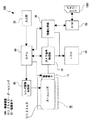
第5レンズ群の像側には撮像素子ユニットIUが配置されている。撮像素子ユニットIUは、撮像面IMGを有する撮像素子とフィルターFLによって構成されている。撮像素子としては、例えば、CCDやCMOS等が用いられ、フィルターFLは、例えば、赤外線カットフィルターやローパスフィルター等によって構成されている。 An image sensor unit IU is disposed on the image side of the fifth lens group. The image sensor unit IU includes an image sensor having an imaging surface IMG and a filter FL. For example, a CCD or CMOS is used as the imaging element, and the filter FL is configured by, for example, an infrared cut filter or a low-pass filter.
<第1の実施の形態>
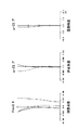
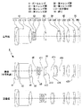
図1は、本発明の第1の実施の形態におけるズームレンズ1のレンズ構成を示している。
<First Embodiment>
FIG. 1 shows a lens configuration of a
ズームレンズ1は、変倍比が3.73倍にされている。
The
ズームレンズ1は、正の屈折力を有する第1レンズ群G1と負の屈折力を有する第2レンズ群G2と正の屈折力を有する第3レンズ群G3と正の屈折力を有する第4レンズ群G4と正の屈折力を有する第5レンズ群G5とが物体側から像側へ順に配置されて成る。
The
第1レンズ群G1は、負の屈折力を有する第1レンズ(前側レンズ)L11と、光軸を90°折り曲げる光学部材としてのプリズムL12と、正の屈折力を有する第3レンズ(後側レンズ)L13とが物体側から像側へ順に配置されて構成されている。 The first lens group G1 includes a first lens (front lens) L11 having negative refractive power, a prism L12 as an optical member that bends the optical axis by 90 °, and a third lens (rear lens) having positive refractive power. ) L13 are arranged in order from the object side to the image side.
第1レンズ群G1はズーミングにおいて光軸方向の位置が固定とされている。第1レンズ群G1にプリズムL12を配置して光軸を90°折り曲げることにより、撮像装置及びズームレンズの厚さ方向における薄型化を図ることができる。 The position of the first lens group G1 in the optical axis direction is fixed during zooming. By arranging the prism L12 in the first lens group G1 and bending the optical axis by 90 °, the imaging device and the zoom lens can be thinned in the thickness direction.
第2レンズ群G2は、負の屈折力を有する第4レンズL21と、負の屈折力を有する第5レンズL22と正の屈折力を有する第6レンズL23とが接合された接合レンズとが物体側から像側へ順に配置されて構成されている。 The second lens group G2 includes a fourth lens L21 having a negative refractive power, and a cemented lens in which a fifth lens L22 having a negative refractive power and a sixth lens L23 having a positive refractive power are cemented. They are arranged in order from the side to the image side.
第2レンズ群G2は広角端から望遠端へのズーミングにおいて物体側から像側へ移動される。 The second lens group G2 is moved from the object side to the image side during zooming from the wide-angle end to the telephoto end.
第2レンズ群G2の第4レンズL21は像側の面が非球面に形成された両凹形状にされている。第4レンズL21を像側の面が非球面に形成された両凹形状にすることにより、広角域における倍率色収差と望遠域におけるコマ収差を効率的に補正することができる。 The fourth lens L21 of the second lens group G2 has a biconcave shape in which the image-side surface is formed as an aspheric surface. By making the fourth lens L21 into a biconcave shape in which the image-side surface is formed as an aspheric surface, it is possible to efficiently correct lateral chromatic aberration in the wide-angle region and coma aberration in the telephoto region.
第3レンズ群G3は、正の屈折力を有する第7レンズL31によって構成されている。 The third lens group G3 includes a seventh lens L31 having a positive refractive power.
第3レンズ群G3はズーミングにおいて光軸方向の位置が固定とされている。 The position of the third lens group G3 in the optical axis direction is fixed during zooming.
第4レンズ群G4は、正の屈折力を有する第8レンズL41と負の屈折力を有する第9レンズL42とが接合された接合レンズによって構成されている。 The fourth lens group G4 includes a cemented lens in which an eighth lens L41 having a positive refractive power and a ninth lens L42 having a negative refractive power are cemented.
第4レンズ群G4は広角端から望遠端へのズーミングにおいて像側から物体側へ移動され、合焦時においても光軸に沿って移動可能とされている。 The fourth lens group G4 is moved from the image side to the object side during zooming from the wide-angle end to the telephoto end, and is movable along the optical axis even during focusing.
第5レンズ群G5は、負の屈折力を有する第10レンズL51と、光軸に直交する方向へ移動することにより像のシフトが可能な正の屈折力を有する第11レンズ(第1正レンズ)L52と、正の屈折力を有する第12レンズ(第2正レンズ)L53とが物体側から像側へ順に配置されて成る。 The fifth lens group G5 includes a tenth lens L51 having a negative refractive power and an eleventh lens (first positive lens) having a positive refractive power capable of shifting an image by moving in a direction orthogonal to the optical axis. ) L52 and a twelfth lens (second positive lens) L53 having a positive refractive power are arranged in order from the object side to the image side.
第5レンズ群G5の第10レンズL51は両凹形状に形成されている。第10レンズL51を両凹形状に形成することにより、広角域における倍率色収差の発生を抑制することができる。 The tenth lens L51 of the fifth lens group G5 is formed in a biconcave shape. By forming the tenth lens L51 into a biconcave shape, it is possible to suppress the occurrence of lateral chromatic aberration in the wide angle region.
第5レンズ群G5の第11レンズL52と第12レンズL53はそれぞれ非球面を有している。第11レンズL52と第12レンズL53に非球面を形成することにより、特に、広角域における像面湾曲を効果的に補正することができ、また、第11レンズL52が光軸に直交する方向へ移動した際の収差の変動を抑制することができる。 The eleventh lens L52 and the twelfth lens L53 of the fifth lens group G5 each have an aspheric surface. By forming aspherical surfaces on the eleventh lens L52 and the twelfth lens L53, it is possible to effectively correct the field curvature particularly in a wide angle region, and the eleventh lens L52 is in a direction perpendicular to the optical axis. It is possible to suppress fluctuations in aberration when moved.
第5レンズ群G5の第11レンズL52と第12レンズL53はともに樹脂材料によって形成されている。第11レンズL52と第12レンズL53を樹脂材料によって形成することにより、コストの低減を図ることができる。また、第11レンズL52を樹脂材料によって形成することにより、軽量化による光軸に直交する方向への移動を容易にすることができる。 Both the eleventh lens L52 and the twelfth lens L53 of the fifth lens group G5 are made of a resin material. The cost can be reduced by forming the eleventh lens L52 and the twelfth lens L53 from a resin material. Further, by forming the eleventh lens L52 from a resin material, the movement in the direction perpendicular to the optical axis can be facilitated by weight reduction.
絞りIRは第3レンズ群G3の像側における近傍に配置されている。 The diaphragm IR is disposed in the vicinity of the third lens group G3 on the image side.
第1の実施の形態におけるズームレンズ1に具体的数値を適用した数値実施例1のレンズデーターを、広角端状態(F=5.18)、中間焦点距離状態(F=9.99)及び望遠端状態(F=19.30)におけるFナンバーFno及び半画角ωとともに表1に示す。
The lens data of Numerical Example 1 in which specific numerical values are applied to the
ズームレンズ1において、広角端状態と望遠端状態の間のズーミングに際して、第1レンズ群G1と第2レンズ群G2の間の面間隔d6、第2レンズ群G2と第3レンズ群G3の間の面間隔d11、絞りIRと第4レンズ群G4の間の面間隔d15及び第4レンズ群G4と第5レンズ群G5の間の面間隔d18が変化する。数値実施例1における各面間隔の広角端状態、中間焦点距離状態及び望遠端状態における可変間隔を表2に示す。
In
ズームレンズ1において、第1レンズ群G1の第3レンズL13の両面(第5面、第6面)、第2レンズ群G2の第4レンズL21の像側の面(第8面)、第3レンズ群G3の第7レンズL31の両面(第12面、第13面)、第4レンズ群G4の第8レンズL41の物体側の面(第16面)、第5レンズ群G5の第11レンズL52の物体側の面(第21面)及び第5レンズ群G5の第12レンズL53の物体側の面(第23面)は非球面に形成されている。数値実施例1における非球面の4次、6次、8次、10次の非球面係数A4、A6、A8、A10を円錐定数Kと共に表3に示す。
In the
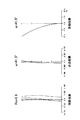
図2乃至図4は数値実施例1の無限遠合焦状態における諸収差図を示し、図2は広角端状態、図3は中間焦点距離状態、図4は望遠端状態における球面収差図、非点収差図、歪曲収差図を示す。 2 to 4 are graphs showing various aberrations in the infinite focus state in Numerical Example 1. FIG. 2 is a wide angle end state, FIG. 3 is an intermediate focal length state, and FIG. 4 is a spherical aberration diagram in a telephoto end state. A point aberration diagram and a distortion aberration diagram are shown.
図2乃至図4には、球面収差図において、実線でd線(波長587.6nm)、一点鎖線でg線(波長435.8nm)、点線でC線(波長656.3nm)における値をそれぞれ示す。非点収差図において、実線でサジタル像面における値を示し、点線でメリディオナル像面における値を示す。 In FIG. 2 to FIG. 4, in the spherical aberration diagrams, values for the d-line (wavelength 587.6 nm) as a solid line, the g-line (wavelength 435.8 nm) as a dashed line, and the C-line (wavelength 656.3 nm) as a dotted line, respectively. Show. In the astigmatism diagram, the solid line indicates the value on the sagittal image plane, and the dotted line indicates the value on the meridional image plane.
各収差図から、数値実施例1は諸収差が良好に補正され、優れた結像性能を有していることが明らかである。 From each aberration diagram, it is clear that Numerical Example 1 has excellent imaging performance with various aberrations corrected well.
<第2の実施の形態>
図5は、本発明の第2の実施の形態におけるズームレンズ2のレンズ構成を示している。
<Second Embodiment>
FIG. 5 shows a lens configuration of the
ズームレンズ2は、変倍比が3.72倍にされている。
The
ズームレンズ2は、正の屈折力を有する第1レンズ群G1と負の屈折力を有する第2レンズ群G2と正の屈折力を有する第3レンズ群G3と正の屈折力を有する第4レンズ群G4と負の屈折力を有する第5レンズ群G5とが物体側から像側へ順に配置されて成る。
The
第1レンズ群G1は、負の屈折力を有する第1レンズ(前側レンズ)L11と、光軸を90°折り曲げる光学部材としてのプリズムL12と、正の屈折力を有する第3レンズ(後側レンズ)L13とが物体側から像側へ順に配置されて構成されている。 The first lens group G1 includes a first lens (front lens) L11 having negative refractive power, a prism L12 as an optical member that bends the optical axis by 90 °, and a third lens (rear lens) having positive refractive power. ) L13 are arranged in order from the object side to the image side.
第1レンズ群G1はズーミングにおいて光軸方向の位置が固定とされている。第1レンズ群G1にプリズムL12を配置して光軸を90°折り曲げることにより、撮像装置及びズームレンズの厚さ方向における薄型化を図ることができる。 The position of the first lens group G1 in the optical axis direction is fixed during zooming. By arranging the prism L12 in the first lens group G1 and bending the optical axis by 90 °, the imaging device and the zoom lens can be thinned in the thickness direction.
第2レンズ群G2は、負の屈折力を有する第4レンズL21と、負の屈折力を有する第5レンズL22と正の屈折力を有する第6レンズL23とが接合された接合レンズとが物体側から像側へ順に配置されて構成されている。 The second lens group G2 includes a fourth lens L21 having a negative refractive power, and a cemented lens in which a fifth lens L22 having a negative refractive power and a sixth lens L23 having a positive refractive power are cemented. They are arranged in order from the side to the image side.
第2レンズ群G2は広角端から望遠端へのズーミングにおいて物体側から像側へ移動される。 The second lens group G2 is moved from the object side to the image side during zooming from the wide-angle end to the telephoto end.
第2レンズ群G2の第4レンズL21は像側の面が非球面に形成された両凹形状にされている。第4レンズL21を像側の面が非球面に形成された両凹形状にすることにより、広角域における倍率色収差と望遠域におけるコマ収差を効率的に補正することができる。 The fourth lens L21 of the second lens group G2 has a biconcave shape in which the image-side surface is formed as an aspheric surface. By making the fourth lens L21 into a biconcave shape in which the image-side surface is formed as an aspheric surface, it is possible to efficiently correct lateral chromatic aberration in the wide-angle region and coma aberration in the telephoto region.
第3レンズ群G3は、正の屈折力を有する第7レンズL31によって構成されている。 The third lens group G3 includes a seventh lens L31 having a positive refractive power.
第3レンズ群G3はズーミングにおいて光軸方向の位置が固定とされている。 The position of the third lens group G3 in the optical axis direction is fixed during zooming.
第4レンズ群G4は、正の屈折力を有する第8レンズL41と負の屈折力を有する第9レンズL42とが接合された接合レンズによって構成されている。 The fourth lens group G4 includes a cemented lens in which an eighth lens L41 having a positive refractive power and a ninth lens L42 having a negative refractive power are cemented.
第4レンズ群G4は広角端から望遠端へのズーミングにおいて像側から物体側へ移動され、合焦時においても光軸に沿って移動可能とされている。 The fourth lens group G4 is moved from the image side to the object side during zooming from the wide-angle end to the telephoto end, and is movable along the optical axis even during focusing.
第5レンズ群G5は、負の屈折力を有する第10レンズL51と、光軸に直交する方向へ移動することにより像のシフトが可能な正の屈折力を有する第11レンズ(第1正レンズ)L52と、正の屈折力を有する第12レンズL53とが物体側から像側へ順に配置されて成る。 The fifth lens group G5 includes a tenth lens L51 having a negative refractive power and an eleventh lens (first positive lens) having a positive refractive power capable of shifting an image by moving in a direction orthogonal to the optical axis. ) L52 and a twelfth lens L53 having a positive refractive power are arranged in order from the object side to the image side.
第5レンズ群G5の第10レンズL51は両凹形状に形成されている。第10レンズL51を両凹形状に形成することにより、広角域における倍率色収差の発生を抑制することができる。 The tenth lens L51 of the fifth lens group G5 is formed in a biconcave shape. By forming the tenth lens L51 into a biconcave shape, it is possible to suppress the occurrence of lateral chromatic aberration in the wide angle region.
第5レンズ群G5の第12レンズL53は非球面を有している。第12レンズL53に非球面を形成することにより、特に、広角域における像面湾曲を効果的に補正することができ、また、第11レンズL52が光軸に直交する方向へ移動した際の収差の変動を抑制することができる。 The twelfth lens L53 of the fifth lens group G5 has an aspheric surface. By forming an aspherical surface on the twelfth lens L53, it is possible to effectively correct the curvature of field particularly in a wide angle region, and the aberration when the eleventh lens L52 moves in the direction perpendicular to the optical axis. Fluctuations can be suppressed.
第5レンズ群G5の第12レンズL53は樹脂材料によって形成されている。第12レンズL53を樹脂材料によって形成することにより、コストの低減を図ることができる。 The twelfth lens L53 of the fifth lens group G5 is made of a resin material. The cost can be reduced by forming the twelfth lens L53 from a resin material.
絞りIRは第3レンズ群G3の像側における近傍に配置されている。 The diaphragm IR is disposed in the vicinity of the third lens group G3 on the image side.
第2の実施の形態におけるズームレンズ2に具体的数値を適用した数値実施例2のレンズデーターを、広角端状態(F=4.61)、中間焦点距離状態(F=8.89)及び望遠端状態(F=17.17)におけるFナンバーFno及び半画角ωとともに表4に示す。
The lens data of Numerical Example 2 in which specific numerical values are applied to the
ズームレンズ2において、広角端状態と望遠端状態の間のズーミングに際して、第1レンズ群G1と第2レンズ群G2の間の面間隔d6、第2レンズ群G2と第3レンズ群G3の間の面間隔d11、絞りIRと第4レンズ群G4の間の面間隔d15及び第4レンズ群G4と第5レンズ群G5の間の面間隔d18が変化する。数値実施例2における各面間隔の広角端状態、中間焦点距離状態及び望遠端状態における可変間隔を表5に示す。
In
ズームレンズ2において、第1レンズ群G1の第1レンズL11の両面(第1面、第2面)、第1レンズ群G1の第3レンズL13の両面(第5面、第6面)、第2レンズ群G2の第4レンズL21の像側の面(第8面)、第3レンズ群G3の第7レンズL31の両面(第12面、第13面)、第4レンズ群G4の第8レンズL41の物体側の面(第16面)及び第5レンズ群G5の第12レンズL53の物体側の面(第23面)は非球面に形成されている。数値実施例2における非球面の4次、6次、8次、10次の非球面係数A4、A6、A8、A10を円錐定数Kと共に表6に示す。
In the
図6乃至図8は数値実施例2の無限遠合焦状態における諸収差図を示し、図6は広角端状態、図7は中間焦点距離状態、図8は望遠端状態における球面収差図、非点収差図、歪曲収差図を示す。 6 to 8 show various aberration diagrams in the infinite focus state in Numerical Example 2, FIG. 6 is a wide angle end state, FIG. 7 is an intermediate focal length state, and FIG. 8 is a spherical aberration diagram in a telephoto end state. A point aberration diagram and a distortion aberration diagram are shown.
図6乃至図8には、球面収差図において、実線でd線(波長587.6nm)、一点鎖線でg線(波長435.8nm)、点線でC線(波長656.3nm)における値をそれぞれ示す。非点収差図において、実線でサジタル像面における値を示し、点線でメリディオナル像面における値を示す。 In FIG. 6 to FIG. 8, in the spherical aberration diagrams, values for the d-line (wavelength 587.6 nm) as a solid line, the g-line (wavelength 435.8 nm) as a dashed line, and the C-line (wavelength 656.3 nm) as a dotted line, respectively. Show. In the astigmatism diagram, the solid line indicates the value on the sagittal image plane, and the dotted line indicates the value on the meridional image plane.
各収差図から、数値実施例2は諸収差が良好に補正され、優れた結像性能を有していることが明らかである。 From each aberration diagram, it is clear that Numerical Example 2 has excellent imaging performance with various aberrations corrected well.
<第3の実施の形態>
図9は、本発明の第3の実施の形態におけるズームレンズ3のレンズ構成を示している。
<Third Embodiment>
FIG. 9 shows the lens configuration of the
ズームレンズ3は、変倍比が3.73倍にされている。
The
ズームレンズ3は、正の屈折力を有する第1レンズ群G1と負の屈折力を有する第2レンズ群G2と正の屈折力を有する第3レンズ群G3と正の屈折力を有する第4レンズ群G4と正の屈折力を有する第5レンズ群G5とが物体側から像側へ順に配置されて成る。
The
第1レンズ群G1は、負の屈折力を有する第1レンズ(前側レンズ)L11と、光軸を90°折り曲げる光学部材としてのプリズムL12と、正の屈折力を有する第3レンズ(後側レンズ)L13とが物体側から像側へ順に配置されて構成されている。 The first lens group G1 includes a first lens (front lens) L11 having negative refractive power, a prism L12 as an optical member that bends the optical axis by 90 °, and a third lens (rear lens) having positive refractive power. ) L13 are arranged in order from the object side to the image side.
第1レンズ群G1はズーミングにおいて光軸方向の位置が固定とされている。第1レンズ群G1にプリズムL12を配置して光軸を90°折り曲げることにより、撮像装置及びズームレンズの厚さ方向における薄型化を図ることができる。 The position of the first lens group G1 in the optical axis direction is fixed during zooming. By arranging the prism L12 in the first lens group G1 and bending the optical axis by 90 °, the imaging device and the zoom lens can be thinned in the thickness direction.
第2レンズ群G2は、負の屈折力を有する第4レンズL21と、負の屈折力を有する第5レンズL22と正の屈折力を有する第6レンズL23とが接合された接合レンズとが物体側から像側へ順に配置されて構成されている。 The second lens group G2 includes a fourth lens L21 having a negative refractive power, and a cemented lens in which a fifth lens L22 having a negative refractive power and a sixth lens L23 having a positive refractive power are cemented. They are arranged in order from the side to the image side.
第2レンズ群G2は広角端から望遠端へのズーミングにおいて物体側から像側へ移動される。 The second lens group G2 is moved from the object side to the image side during zooming from the wide-angle end to the telephoto end.
第2レンズ群G2の第4レンズL21は物体側の面と像側の面が非球面に形成された両凹形状にされている。第4レンズL21を像側の面が非球面に形成された両凹形状にすることにより、広角域における倍率色収差と望遠域におけるコマ収差を効率的に補正することができる。 The fourth lens L21 of the second lens group G2 has a biconcave shape in which the object-side surface and the image-side surface are formed as aspheric surfaces. By making the fourth lens L21 into a biconcave shape in which the image-side surface is formed as an aspheric surface, it is possible to efficiently correct lateral chromatic aberration in the wide-angle region and coma aberration in the telephoto region.
第3レンズ群G3は、正の屈折力を有する第7レンズL31によって構成されている。 The third lens group G3 includes a seventh lens L31 having a positive refractive power.
第3レンズ群G3はズーミングにおいて光軸方向の位置が固定とされている。 The position of the third lens group G3 in the optical axis direction is fixed during zooming.
第4レンズ群G4は、正の屈折力を有する第8レンズL41と負の屈折力を有する第9レンズL42とが接合された接合レンズによって構成されている。 The fourth lens group G4 includes a cemented lens in which an eighth lens L41 having a positive refractive power and a ninth lens L42 having a negative refractive power are cemented.
第4レンズ群G4は広角端から望遠端へのズーミングにおいて像側から物体側へ移動され、合焦時においても光軸に沿って移動可能とされている。 The fourth lens group G4 is moved from the image side to the object side during zooming from the wide-angle end to the telephoto end, and is movable along the optical axis even during focusing.
第5レンズ群G5は、負の屈折力を有する第10レンズL51と、光軸に直交する方向へ移動することにより像のシフトが可能な正の屈折力を有する第11レンズ(第1正レンズ)L52と、正の屈折力を有する第12レンズ(第2正レンズ)L53とが物体側から像側へ順に配置されて成る。 The fifth lens group G5 includes a tenth lens L51 having a negative refractive power and an eleventh lens (first positive lens) having a positive refractive power capable of shifting an image by moving in a direction orthogonal to the optical axis. ) L52 and a twelfth lens (second positive lens) L53 having a positive refractive power are arranged in order from the object side to the image side.
第5レンズ群G5の第10レンズL51は両凹形状に形成されている。第10レンズL51を両凹形状に形成することにより、広角域における倍率色収差の発生を抑制することができる。 The tenth lens L51 of the fifth lens group G5 is formed in a biconcave shape. By forming the tenth lens L51 into a biconcave shape, it is possible to suppress the occurrence of lateral chromatic aberration in the wide angle region.
また、第5レンズ群G5の第10レンズL51は物体側の面と像側の面の曲率半径が同一にされている。第10レンズL51の物体側の面と像側の面の曲率半径を同一にすることにより、形状が光軸方向において対称になり、ズームレンズ3の組立の容易化を図ることができる。
The tenth lens L51 of the fifth lens group G5 has the same radius of curvature on the object side surface and the image side surface. By making the curvature radius of the object side surface and the image side surface of the tenth lens L51 the same, the shape becomes symmetrical in the optical axis direction, and the
第5レンズ群G5の第11レンズL52と第12レンズL53はそれぞれ非球面を有している。第11レンズL52と第12レンズL53に非球面を形成することにより、特に、広角域における像面湾曲を効果的に補正することができ、また、第11レンズL52が光軸に直交する方向へ移動した際の収差の変動を抑制することができる。 The eleventh lens L52 and the twelfth lens L53 of the fifth lens group G5 each have an aspheric surface. By forming aspherical surfaces on the eleventh lens L52 and the twelfth lens L53, it is possible to effectively correct the field curvature particularly in a wide angle region, and the eleventh lens L52 is in a direction perpendicular to the optical axis. It is possible to suppress fluctuations in aberration when moved.
第5レンズ群G5の第11レンズL52は樹脂材料によって形成されている。第11レンズL52を樹脂材料によって形成することにより、コストの低減を図ることができると共に軽量化による光軸に直交する方向への移動を容易にすることができる。 The eleventh lens L52 of the fifth lens group G5 is made of a resin material. By forming the eleventh lens L52 from a resin material, the cost can be reduced and the movement in the direction perpendicular to the optical axis can be facilitated by weight reduction.
絞りIRは第3レンズ群G3の像側における近傍に配置されている。 The diaphragm IR is disposed in the vicinity of the third lens group G3 on the image side.
第3の実施の形態におけるズームレンズ3に具体的数値を適用した数値実施例3のレンズデーターを、広角端状態(F=4.59)、中間焦点距離状態(F=8.69)及び望遠端状態(F=17.10)におけるFナンバーFno及び半画角ωとともに表7に示す。
The lens data of Numerical Example 3 in which specific numerical values are applied to the
ズームレンズ3において、広角端状態と望遠端状態の間のズーミングに際して、第1レンズ群G1と第2レンズ群G2の間の面間隔d6、第2レンズ群G2と第3レンズ群G3の間の面間隔d11、絞りIRと第4レンズ群G4の間の面間隔d15及び第4レンズ群G4と第5レンズ群G5の間の面間隔d18が変化する。数値実施例3における各面間隔の広角端状態、中間焦点距離状態及び望遠端状態における可変間隔を表8に示す。
In
ズームレンズ3において、第1レンズ群G1の第3レンズL13の両面(第5面、第6面)、第2レンズ群G2の第4レンズL21の両面(第7面、第8面)、第3レンズ群G3の第7レンズL31の両面(第12面、第13面)、第4レンズ群G4の第8レンズL41の物体側の面(第16面)、第5レンズ群G5の第11レンズL52の両面(第21面、第22面)及び第5レンズ群G5の第12レンズL53の物体側の面(第23面)は非球面に形成されている。数値実施例3における非球面の4次、6次、8次、10次の非球面係数A4、A6、A8、A10を円錐定数Kと共に表9に示す。
In the
図10乃至図12は数値実施例3の無限遠合焦状態における諸収差図を示し、図10は広角端状態、図11は中間焦点距離状態、図12は望遠端状態における球面収差図、非点収差図、歪曲収差図を示す。 10 to 12 are graphs showing various aberrations in the infinite focus state in Numerical Example 3. FIG. 10 is a wide-angle end state, FIG. 11 is an intermediate focal length state, and FIG. 12 is a spherical aberration diagram in a telephoto end state. A point aberration diagram and a distortion aberration diagram are shown.
図10乃至図12には、球面収差図において、実線でd線(波長587.6nm)、一点鎖線でg線(波長435.8nm)、点線でC線(波長656.3nm)における値をそれぞれ示す。非点収差図において、実線でサジタル像面における値を示し、点線でメリディオナル像面における値を示す。 In FIG. 10 to FIG. 12, in the spherical aberration diagrams, values for the d-line (wavelength 587.6 nm) as a solid line, the g-line (wavelength 435.8 nm) as a one-dot chain line, and the C-line (wavelength 656.3 nm) as a dotted line, respectively. Show. In the astigmatism diagram, the solid line indicates the value on the sagittal image plane, and the dotted line indicates the value on the meridional image plane.
各収差図から、数値実施例3は諸収差が良好に補正され、優れた結像性能を有していることが明らかである。 From each aberration diagram, it is clear that Numerical Example 3 has excellent imaging performance with various aberrations corrected well.
<第4の実施の形態>
図13は、本発明の第4の実施の形態におけるズームレンズ4のレンズ構成を示している。
<Fourth embodiment>
FIG. 13 shows the lens configuration of the zoom lens 4 according to the fourth embodiment of the present invention.
ズームレンズ4は、変倍比が3.07倍にされている。 The zoom lens 4 has a zoom ratio of 3.07.
ズームレンズ4は、正の屈折力を有する第1レンズ群G1と負の屈折力を有する第2レンズ群G2と正の屈折力を有する第3レンズ群G3と正の屈折力を有する第4レンズ群G4と正の屈折力を有する第5レンズ群G5とが物体側から像側へ順に配置されて成る。 The zoom lens 4 includes a first lens group G1 having a positive refractive power, a second lens group G2 having a negative refractive power, a third lens group G3 having a positive refractive power, and a fourth lens having a positive refractive power. A group G4 and a fifth lens group G5 having positive refractive power are arranged in order from the object side to the image side.
第1レンズ群G1は、負の屈折力を有する第1レンズ(前側レンズ)L11と、光軸を90°折り曲げる光学部材としてのプリズムL12と、正の屈折力を有する第3レンズ(後側レンズ)L13とが物体側から像側へ順に配置されて構成されている。 The first lens group G1 includes a first lens (front lens) L11 having negative refractive power, a prism L12 as an optical member that bends the optical axis by 90 °, and a third lens (rear lens) having positive refractive power. ) L13 are arranged in order from the object side to the image side.
第1レンズ群G1はズーミングにおいて光軸方向の位置が固定とされている。第1レンズ群G1にプリズムL12を配置して光軸を90°折り曲げることにより、撮像装置及びズームレンズの厚さ方向における薄型化を図ることができる。 The position of the first lens group G1 in the optical axis direction is fixed during zooming. By arranging the prism L12 in the first lens group G1 and bending the optical axis by 90 °, the imaging device and the zoom lens can be thinned in the thickness direction.
第2レンズ群G2は、負の屈折力を有する第4レンズL21と、負の屈折力を有する第5レンズL22と正の屈折力を有する第6レンズL23とが接合された接合レンズとが物体側から像側へ順に配置されて構成されている。 The second lens group G2 includes a fourth lens L21 having a negative refractive power, and a cemented lens in which a fifth lens L22 having a negative refractive power and a sixth lens L23 having a positive refractive power are cemented. They are arranged in order from the side to the image side.
第2レンズ群G2は広角端から望遠端へのズーミングにおいて物体側から像側へ移動される。 The second lens group G2 is moved from the object side to the image side during zooming from the wide-angle end to the telephoto end.
第2レンズ群G2の第4レンズL21は像側の面が非球面に形成された両凹形状にされている。第4レンズL21を像側の面が非球面に形成された両凹形状にすることにより、広角域における倍率色収差と望遠域におけるコマ収差を効率的に補正することができる。 The fourth lens L21 of the second lens group G2 has a biconcave shape in which the image-side surface is formed as an aspheric surface. By making the fourth lens L21 into a biconcave shape in which the image-side surface is formed as an aspheric surface, it is possible to efficiently correct lateral chromatic aberration in the wide-angle region and coma aberration in the telephoto region.
第3レンズ群G3は、正の屈折力を有する第7レンズL31によって構成されている。 The third lens group G3 includes a seventh lens L31 having a positive refractive power.
第3レンズ群G3はズーミングにおいて光軸方向の位置が固定とされている。 The position of the third lens group G3 in the optical axis direction is fixed during zooming.
第4レンズ群G4は、正の屈折力を有する第8レンズL41と負の屈折力を有する第9レンズL42とが接合された接合レンズによって構成されている。 The fourth lens group G4 includes a cemented lens in which an eighth lens L41 having a positive refractive power and a ninth lens L42 having a negative refractive power are cemented.
第4レンズ群G4は広角端から望遠端へのズーミングにおいて像側から物体側へ移動され、合焦時においても光軸に沿って移動可能とされている。 The fourth lens group G4 is moved from the image side to the object side during zooming from the wide-angle end to the telephoto end, and is movable along the optical axis even during focusing.
第5レンズ群G5は、負の屈折力を有する第10レンズL51と、光軸に直交する方向へ移動することにより像のシフトが可能な正の屈折力を有する第11レンズ(第1正レンズ)L52と、負の屈折力を有する第12レンズL53とが物体側から像側へ順に配置されて成る。 The fifth lens group G5 includes a tenth lens L51 having a negative refractive power and an eleventh lens (first positive lens) having a positive refractive power capable of shifting an image by moving in a direction orthogonal to the optical axis. ) L52 and a twelfth lens L53 having negative refractive power are arranged in order from the object side to the image side.
第5レンズ群G5の第10レンズL51は両凹形状に形成されている。第10レンズL51を両凹形状に形成することにより、広角域における倍率色収差の発生を抑制することができる。 The tenth lens L51 of the fifth lens group G5 is formed in a biconcave shape. By forming the tenth lens L51 into a biconcave shape, it is possible to suppress the occurrence of lateral chromatic aberration in the wide angle region.
第5レンズ群G5の第12レンズL53は非球面を有している。第12レンズL53に非球面を形成することにより、特に、広角域における像面湾曲を効果的に補正することができ、また、第11レンズL52が光軸に直交する方向へ移動した際の収差の変動を抑制することができる。 The twelfth lens L53 of the fifth lens group G5 has an aspheric surface. By forming an aspherical surface on the twelfth lens L53, it is possible to effectively correct the curvature of field particularly in a wide angle region, and the aberration when the eleventh lens L52 moves in the direction perpendicular to the optical axis. Fluctuations can be suppressed.
第5レンズ群G5の第11レンズL52は樹脂材料によって形成されている。第11レンズL52を樹脂材料によって形成することにより、コストの低減を図ることができると共に軽量化による光軸に直交する方向への移動を容易にすることができる。 The eleventh lens L52 of the fifth lens group G5 is made of a resin material. By forming the eleventh lens L52 from a resin material, the cost can be reduced and the movement in the direction perpendicular to the optical axis can be facilitated by weight reduction.
絞りIRは第3レンズ群G3の像側における近傍に配置されている。 The diaphragm IR is disposed in the vicinity of the third lens group G3 on the image side.
第4の実施の形態におけるズームレンズ4に具体的数値を適用した数値実施例4のレンズデーターを、広角端状態(F=5.17)、中間焦点距離状態(F=9.06)及び望遠端状態(F=15.89)におけるFナンバーFno及び半画角ωとともに表10に示す。 The lens data of Numerical Example 4 in which specific numerical values are applied to the zoom lens 4 according to the fourth embodiment are the wide-angle end state (F = 5.17), the intermediate focal length state (F = 9.06), and the telephoto lens. Table 10 shows the F number Fno and the half angle of view ω in the end state (F = 15.89).
ズームレンズ4において、広角端状態と望遠端状態の間のズーミングに際して、第1レンズ群G1と第2レンズ群G2の間の面間隔d6、第2レンズ群G2と第3レンズ群G3の間の面間隔d11、絞りIRと第4レンズ群G4の間の面間隔d15及び第4レンズ群G4と第5レンズ群G5の間の面間隔d18が変化する。数値実施例4における各面間隔の広角端状態、中間焦点距離状態及び望遠端状態における可変間隔を表11に示す。 In zoom lens 4, during zooming between the wide-angle end state and the telephoto end state, the surface distance d6 between the first lens group G1 and the second lens group G2, and the distance between the second lens group G2 and the third lens group G3. The surface distance d11, the surface distance d15 between the stop IR and the fourth lens group G4, and the surface distance d18 between the fourth lens group G4 and the fifth lens group G5 change. Table 11 shows variable intervals in the wide-angle end state, the intermediate focal length state, and the telephoto end state of each surface interval in Numerical Example 4.
ズームレンズ4において、第1レンズ群G1の第1レンズL11の両面(第1面、第2面)、第1レンズ群G1の第3レンズL13の両面(第5面、第6面)、第2レンズ群G2の第4レンズL21の像側の面(第8面)、第3レンズ群G3の第7レンズL31の両面(第12面、第13面)、第4レンズ群G4の第8レンズL41の物体側の面(第16面)及び第5レンズ群G5の第12レンズL53の物体側の面(第23面)は非球面に形成されている。数値実施例4における非球面の4次、6次、8次、10次の非球面係数A4、A6、A8、A10を円錐定数Kと共に表12に示す。 In the zoom lens 4, both surfaces (first surface, second surface) of the first lens L11 of the first lens group G1, both surfaces (fifth surface, sixth surface) of the third lens L13 of the first lens group G1, The image side surface (eighth surface) of the fourth lens L21 of the second lens group G2, the both surfaces (the twelfth surface and the thirteenth surface) of the seventh lens L31 of the third lens group G3, and the eighth surface of the fourth lens group G4. The object side surface (the 16th surface) of the lens L41 and the object side surface (the 23rd surface) of the twelfth lens L53 of the fifth lens group G5 are aspheric. Table 12 shows the fourth-order, sixth-order, eighth-order, and tenth-order aspheric coefficients A4, A6, A8, and A10 of the aspheric surface in Numerical Example 4 together with the conic constant K.
図14乃至図16は数値実施例4の無限遠合焦状態における諸収差図を示し、図14は広角端状態、図15は中間焦点距離状態、図16は望遠端状態における球面収差図、非点収差図、歪曲収差図を示す。 FIGS. 14 to 16 show various aberration diagrams in the infinite focus state in Numerical Example 4, FIG. 14 is a wide-angle end state, FIG. 15 is an intermediate focal length state, and FIG. 16 is a spherical aberration diagram in a telephoto end state. A point aberration diagram and a distortion aberration diagram are shown.
図14乃至図16には、球面収差図において、実線でd線(波長587.6nm)、一点鎖線でg線(波長435.8nm)、点線でC線(波長656.3nm)における値をそれぞれ示す。非点収差図において、実線でサジタル像面における値を示し、点線でメリディオナル像面における値を示す。 In FIG. 14 to FIG. 16, in the spherical aberration diagrams, values for the d-line (wavelength 587.6 nm) as a solid line, the g-line (wavelength 435.8 nm) as a dashed-dotted line, and the C-line (wavelength 656.3 nm) as a dotted line, respectively. Show. In the astigmatism diagram, the solid line indicates the value on the sagittal image plane, and the dotted line indicates the value on the meridional image plane.
各収差図から、数値実施例4は諸収差が良好に補正され、優れた結像性能を有していることが明らかである。 From each aberration diagram, it is clear that Numerical Example 4 has excellent imaging performance with various aberrations corrected well.
<第5の実施の形態>
図17は、本発明の第5の実施の形態におけるズームレンズ5のレンズ構成を示している。
<Fifth embodiment>
FIG. 17 shows the lens configuration of the
ズームレンズ5は、変倍比が3.73倍にされている。
The
ズームレンズ5は、正の屈折力を有する第1レンズ群G1と負の屈折力を有する第2レンズ群G2と正の屈折力を有する第3レンズ群G3と正の屈折力を有する第4レンズ群G4と負の屈折力を有する第5レンズ群G5とが物体側から像側へ順に配置されて成る。
The
第1レンズ群G1は、負の屈折力を有する第1レンズ(前側レンズ)L11と、光軸を90°折り曲げる光学部材としてのプリズムL12と、正の屈折力を有する第3レンズ(後側レンズ)L13とが物体側から像側へ順に配置されて構成されている。 The first lens group G1 includes a first lens (front lens) L11 having negative refractive power, a prism L12 as an optical member that bends the optical axis by 90 °, and a third lens (rear lens) having positive refractive power. ) L13 are arranged in order from the object side to the image side.
第1レンズ群G1はズーミングにおいて光軸方向の位置が固定とされている。第1レンズ群G1にプリズムL12を配置して光軸を90°折り曲げることにより、撮像装置及びズームレンズの厚さ方向における薄型化を図ることができる。 The position of the first lens group G1 in the optical axis direction is fixed during zooming. By arranging the prism L12 in the first lens group G1 and bending the optical axis by 90 °, the imaging device and the zoom lens can be thinned in the thickness direction.
第2レンズ群G2は、負の屈折力を有する第4レンズL21と、負の屈折力を有する第5レンズL22と正の屈折力を有する第6レンズL23とが接合された接合レンズと、負の屈折力を有する第7レンズL24とが物体側から像側へ順に配置されて構成されている。 The second lens group G2 includes a cemented lens in which a fourth lens L21 having a negative refractive power, a fifth lens L22 having a negative refractive power, and a sixth lens L23 having a positive refractive power are cemented, The seventh lens L24 having a refractive power of is arranged in order from the object side to the image side.
第2レンズ群G2は広角端から望遠端へのズーミングにおいて物体側から像側へ移動される。 The second lens group G2 is moved from the object side to the image side during zooming from the wide-angle end to the telephoto end.
第2レンズ群G2の第4レンズL21は物体側の面と像側の面が非球面に形成された両凹形状にされている。第4レンズL21を像側の面が非球面に形成された両凹形状にすることにより、広角域における倍率色収差と望遠域におけるコマ収差を効率的に補正することができる。 The fourth lens L21 of the second lens group G2 has a biconcave shape in which the object-side surface and the image-side surface are formed as aspheric surfaces. By making the fourth lens L21 into a biconcave shape in which the image-side surface is formed as an aspheric surface, it is possible to efficiently correct lateral chromatic aberration in the wide-angle region and coma aberration in the telephoto region.
第3レンズ群G3は、正の屈折力を有する第8レンズL31によって構成されている。 The third lens group G3 includes an eighth lens L31 having a positive refractive power.
第3レンズ群G3はズーミングにおいて光軸方向の位置が固定とされている。 The position of the third lens group G3 in the optical axis direction is fixed during zooming.
第4レンズ群G4は、正の屈折力を有する第9レンズL41と負の屈折力を有する第10レンズL42とが接合された接合レンズによって構成されている。 The fourth lens group G4 includes a cemented lens in which a ninth lens L41 having a positive refractive power and a tenth lens L42 having a negative refractive power are cemented.
第4レンズ群G4は広角端から望遠端へのズーミングにおいて像側から物体側へ移動され、合焦時においても光軸に沿って移動可能とされている。 The fourth lens group G4 is moved from the image side to the object side during zooming from the wide-angle end to the telephoto end, and is movable along the optical axis even during focusing.
第5レンズ群G5は、負の屈折力を有する第11レンズL51と、光軸に直交する方向へ移動することにより像のシフトが可能な正の屈折力を有する第12レンズ(第1正レンズ)L52と、正の屈折力を有する第13レンズ(第2正レンズ)L53とが物体側から像側へ順に配置されて成る。 The fifth lens group G5 includes an eleventh lens L51 having negative refractive power and a twelfth lens (first positive lens) having positive refractive power capable of shifting an image by moving in a direction orthogonal to the optical axis. ) L52 and a thirteenth lens (second positive lens) L53 having a positive refractive power are arranged in order from the object side to the image side.
第5レンズ群G5の第13レンズL53は非球面を有している。第13レンズL53に非球面を形成することにより、特に、広角域における像面湾曲を効果的に補正することができ、また、第12レンズL52が光軸に直交する方向へ移動した際の収差の変動を抑制することができる。 The thirteenth lens L53 of the fifth lens group G5 has an aspheric surface. By forming an aspherical surface on the thirteenth lens L53, it is possible to effectively correct the curvature of field particularly in the wide-angle range, and the aberration when the twelfth lens L52 moves in the direction perpendicular to the optical axis. Fluctuations can be suppressed.
第5レンズ群G5の第13レンズL53は樹脂材料によって形成されている。第13レンズL53を樹脂材料によって形成することにより、コストの低減を図ることができる。 The thirteenth lens L53 of the fifth lens group G5 is made of a resin material. The cost can be reduced by forming the thirteenth lens L53 from a resin material.
絞りIRは第3レンズ群G3の像側における近傍に配置されている。 The diaphragm IR is disposed in the vicinity of the third lens group G3 on the image side.
第5の実施の形態におけるズームレンズ5に具体的数値を適用した数値実施例5のレンズデーターを、広角端状態(F=5.20)、中間焦点距離状態(F=10.00)及び望遠端状態(F=19.40)におけるFナンバーFno及び半画角ωとともに表13に示す。
The lens data of Numerical Example 5 in which specific numerical values are applied to the
ズームレンズ5において、広角端状態と望遠端状態の間のズーミングに際して、第1レンズ群G1と第2レンズ群G2の間の面間隔d6、第2レンズ群G2と第3レンズ群G3の間の面間隔d13、絞りIRと第4レンズ群G4の間の面間隔d17及び第4レンズ群G4と第5レンズ群G5の間の面間隔d20が変化する。数値実施例5における各面間隔の広角端状態、中間焦点距離状態及び望遠端状態における可変間隔を表14に示す。
In
ズームレンズ5において、第1レンズ群G1の第3レンズL13の両面(第5面、第6面)、第2レンズ群G2の第4レンズL21の両面(第7面、第8面)、第3レンズ群G3の第8レンズL31の両面(第14面、第15面)、第4レンズ群G4の第9レンズL41の物体側の面(第18面)及び第5レンズ群G5の第13レンズL53の両面(第25面、第26面)は非球面に形成されている。数値実施例5における非球面の4次、6次、8次、10次の非球面係数A4、A6、A8、A10を円錐定数Kと共に表15に示す。
In the
図18乃至図20は数値実施例5の無限遠合焦状態における諸収差図を示し、図18は広角端状態、図19は中間焦点距離状態、図20は望遠端状態における球面収差図、非点収差図、歪曲収差図を示す。 18 to 20 show various aberration diagrams in the infinite focus state in Numerical Example 5, FIG. 18 is a wide-angle end state, FIG. 19 is an intermediate focal length state, and FIG. 20 is a spherical aberration diagram in the telephoto end state. A point aberration diagram and a distortion aberration diagram are shown.
図18乃至図20には、球面収差図において、実線でd線(波長587.6nm)、一点鎖線でg線(波長435.8nm)、点線でC線(波長656.3nm)における値をそれぞれ示す。非点収差図において、実線でサジタル像面における値を示し、点線でメリディオナル像面における値を示す。 In FIG. 18 to FIG. 20, in the spherical aberration diagrams, the values for the d-line (wavelength 587.6 nm) as a solid line, the g-line (wavelength 435.8 nm) as a dashed line, and the C-line (wavelength 656.3 nm) as a dotted line, respectively. Show. In the astigmatism diagram, the solid line indicates the value on the sagittal image plane, and the dotted line indicates the value on the meridional image plane.
各収差図から、数値実施例5は諸収差が良好に補正され、優れた結像性能を有していることが明らかである。 From each aberration diagram, it is clear that Numerical Example 5 has excellent imaging performance with various aberrations corrected well.
[ズームレンズの条件式の各値]
以下に、本発明ズームレンズの条件式の各値について説明する。
[Each value of conditional expression of zoom lens]
Hereinafter, each value of the conditional expression of the zoom lens of the present invention will be described.
表16にズームレンズ1乃至ズームレンズ5における前記条件式(1)乃至条件式(11)の各値を示す。
Table 16 shows values of the conditional expressions (1) to (11) in the
表16から明らかなように、ズームレンズ1乃至ズームレンズ5は条件式(1)乃至条件式(11)を満足するようにされている。
As apparent from Table 16, the
[撮像装置の構成]
以下に、本発明撮像装置について説明する。
[Configuration of imaging device]
The imaging device of the present invention will be described below.
本発明撮像装置は、ズームレンズと該ズームレンズによって形成された光学像を電気的信号に変換する撮像素子とを備えた装置である。 The imaging apparatus of the present invention is an apparatus that includes a zoom lens and an imaging element that converts an optical image formed by the zoom lens into an electrical signal.
本発明撮像装置は、ズームレンズと該ズームレンズによって形成された光学像を電気的信号に変換する撮像素子とを備え、ズームレンズが、正の屈折力を有する第1レンズ群と負の屈折力を有する第2レンズ群と正の屈折力を有する第3レンズ群と正の屈折力を有する第4レンズ群と正又は負の屈折力を有する第5レンズ群とが物体側から像側へ順に配置されて成る。 The image pickup apparatus of the present invention includes a zoom lens and an image pickup element that converts an optical image formed by the zoom lens into an electrical signal. The zoom lens includes a first lens group having a positive refractive power and a negative refractive power. A second lens group having positive refractive power, a third lens group having positive refractive power, a fourth lens group having positive refractive power, and a fifth lens group having positive or negative refractive power in order from the object side to the image side. It is arranged.
また、本発明撮像装置は、ズームレンズが、ズーミングにおいて第2レンズ群と第4レンズ群が光軸方向へ移動される。 In the imaging apparatus of the present invention, the zoom lens moves the second lens group and the fourth lens group in the optical axis direction during zooming.
さらに、本発明撮像装置は、ズームレンズの第1レンズ群がズーミングにおいて光軸方向の位置が固定とされると共に負の屈折力を有する前側レンズと光路を折り曲げる光学部材と正の屈折力を有する後側レンズとが物体側から像側へ順に配置されて成る。 Furthermore, the imaging apparatus of the present invention has a positive lens having a positive lens, a front lens having a negative refractive power, a front lens having a negative refractive power, the first lens group of the zoom lens being fixed in zooming, and a positive refractive power. A rear lens is arranged in order from the object side to the image side.
加えて、本発明撮像装置は、ズームレンズの第3レンズ群がズーミングにおいて光軸方向の位置が固定とされ、絞りが第2レンズ群と第3レンズ群の間又は第3レンズ群と第4レンズ群の間に配置され、以下の条件式(1)、条件式(2)及び条件式(3)を満足する。
(1)1.8<F1/FW<3.0
(2)2.0<D1G/FW<3.3
(3)2.0<DIA11/DIA21<3.0
但し、
F1:第1レンズ群の焦点距離
D1G:第1レンズ群の光軸上の厚さ
FW:広角端におけるレンズ全系の焦点距離
DIA11:第1レンズ群の最も物体側のレンズ面の広角端における有効径
DIA21:第2レンズ群の最も物体側のレンズ面の広角端における有効径
とする。
In addition, in the imaging apparatus of the present invention, the position of the third lens group of the zoom lens in the optical axis direction is fixed during zooming, and the stop is located between the second lens group and the third lens group or the third lens group and the fourth lens group. Arranged between the lens groups, the following conditional expression (1), conditional expression (2) and conditional expression (3) are satisfied.
(1) 1.8 <F1 / FW <3.0
(2) 2.0 <D1G / FW <3.3
(3) 2.0 <DIA11 / DIA21 <3.0
However,
F1: Focal length D1G of the first lens group: Thickness on the optical axis of the first lens group FW: Focal length of the entire lens system at the wide angle end DIA11: At the wide angle end of the lens surface closest to the object side of the first lens group Effective diameter DIA21: The effective diameter at the wide-angle end of the lens surface closest to the object side in the second lens group.
本発明撮像装置は、ズームレンズが上記のような構成とされているため、以下のような効果が得られる。 Since the zoom lens has the above-described configuration, the imaging apparatus according to the present invention has the following effects.
ズーミングを行う際の第2レンズ群と第4レンズ群の移動方向が、第1レンズ群の後側レンズの光軸方向、即ち、光学部材によって光路が折り曲げられた方向となり、レンズ系の薄型化を図ることができる。 The moving direction of the second lens group and the fourth lens group during zooming becomes the optical axis direction of the rear lens of the first lens group, that is, the direction in which the optical path is bent by the optical member, and the lens system is made thinner. Can be achieved.
また、絞りが第2レンズ群と第3レンズ群の間又は第3レンズ群と第4レンズ群の間に配置されているため、5群ズーム構成の中央付近に絞りを配置することが可能となり、第1レンズ群から第5レンズ群までの有効径を小型化することができ、レンズ系の薄型化を図ることができる。 In addition, since the diaphragm is disposed between the second lens group and the third lens group or between the third lens group and the fourth lens group, the diaphragm can be disposed near the center of the five-group zoom configuration. The effective diameter from the first lens group to the fifth lens group can be reduced, and the lens system can be made thinner.
条件式(1)は、第1レンズ群の焦点距離を規定する式である。第1レンズ群の焦点距離を適切に規定することにより、広角ズームレンズでありながら広角端における軸外収差の発生が少ない小型のズームレンズを実現することができる。 Conditional expression (1) defines the focal length of the first lens group. By appropriately defining the focal length of the first lens group, it is possible to realize a small zoom lens that is a wide-angle zoom lens and generates less off-axis aberrations at the wide-angle end.
条件式(1)の下限を下回ると、第1レンズ群の焦点距離が小さくなり過ぎるため、第1レンズ群の後側レンズの屈折力が強くなり過ぎ、広角側において倍率色収差が増加し、望遠側において軸上色収差が増加してしまう。また、前側レンズと後側レンズの屈折力が一定である場合には、前側レンズと後側レンズの光軸上の距離が増加してしまい、光学系の薄型化が困難となる。 If the lower limit of conditional expression (1) is not reached, the focal length of the first lens group becomes too small, the refractive power of the rear lens of the first lens group becomes too strong, the lateral chromatic aberration increases on the wide angle side, and the telephoto On the side, axial chromatic aberration increases. In addition, when the refractive power of the front lens and the rear lens is constant, the distance on the optical axis between the front lens and the rear lens increases, making it difficult to reduce the thickness of the optical system.
逆に、条件式(1)の上限を上回ると、第1レンズ群の焦点距離が大きくなり過ぎるため、変倍のための第2レンズ群の大きな移動量を確保する必要が生じ、第1レンズ群と第3レンズ群の距離が大きくなってしまう。また、第1レンズ群の前側レンズから絞りまでの距離が大きくなると、入射瞳位置が前側レンズから像側に遠去かるため、広角化した場合に前側レンズ及び光学部材の径が大きくなり、薄型化に支障を来たしてしまう。 On the contrary, if the upper limit of conditional expression (1) is exceeded, the focal length of the first lens group becomes too large, so that it is necessary to ensure a large amount of movement of the second lens group for zooming. The distance between the lens group and the third lens group becomes large. Further, when the distance from the front lens of the first lens group to the stop increases, the entrance pupil position moves away from the front lens to the image side. Therefore, when the angle is widened, the diameters of the front lens and the optical member are increased, and the thickness is reduced. It will interfere with the transformation.
条件式(2)は、光軸を折り曲げる光学部材を含む第1レンズ群の光軸上の厚さを規定する式である。第1レンズ群の焦点距離が条件式(1)を満足した上で、第1レンズ群の光軸上の厚さを適切に規定して条件式(2)を満足することにより、広角ズームレンズでありながら小型化及び薄型化を図ることができる。 Conditional expression (2) is an expression that defines the thickness on the optical axis of the first lens group including the optical member that bends the optical axis. When the focal length of the first lens group satisfies the conditional expression (1), and the thickness on the optical axis of the first lens group is appropriately defined to satisfy the conditional expression (2), the wide-angle zoom lens However, the size and thickness can be reduced.
条件式(2)の下限を下回ると、前側レンズと後側レンズの距離が小さくなり過ぎるため、光学部材の光路を折り曲げるための十分な長さの確保が困難となる。また、前側レンズ又は後側レンズの屈折力が強くなり過ぎてしまい、広角側において倍率色収差が増加し、望遠側において軸上色収差が増加してしまう。 If the lower limit of conditional expression (2) is not reached, the distance between the front lens and the rear lens becomes too small, and it becomes difficult to secure a sufficient length for bending the optical path of the optical member. Further, the refractive power of the front lens or the rear lens becomes too strong, the lateral chromatic aberration increases on the wide angle side, and the axial chromatic aberration increases on the telephoto side.
逆に、条件式(2)の上限を上回ると、前側レンズの屈折力が弱くなり過ぎるため、前側レンズ及び光学部材の径と光軸上の厚さが大きくなり、光路を折り曲げた際の撮像装置及びズームレンズの厚さが増し、薄型化に支障を来たしてしまう。 On the contrary, if the upper limit of conditional expression (2) is exceeded, the refractive power of the front lens becomes too weak, so the diameter of the front lens and the optical member and the thickness on the optical axis become large, and imaging when the optical path is bent is performed. The thickness of the device and the zoom lens increases, which hinders thinning.
条件式(3)は、第1レンズ群の最も物体側のレンズ面の有効径と第2レンズ群の最も物体側のレンズ面の有効径との比を規定する式である。第1レンズ群の最も物体側のレンズ面の有効径と第2レンズ群の最も物体側のレンズ面の有効径との比を適切に規定することにより、広角ズームレンズでありながら第1レンズ群を小型化して薄型化を図ることができる。 Conditional expression (3) defines the ratio between the effective diameter of the lens surface closest to the object side of the first lens group and the effective diameter of the lens surface closest to the object side of the second lens group. By appropriately defining the ratio between the effective diameter of the lens surface closest to the object side of the first lens group and the effective diameter of the lens surface closest to the object side of the second lens group, the first lens group is a wide-angle zoom lens. The size can be reduced by reducing the size.
条件式(3)の下限を下回ると、第2レンズ群の有効径が大きくなり過ぎ、最大画角光線の第2レンズ群中の光路が光軸から離れた部分を通過することになるため、第2レンズ群の光軸上の厚さが増加し、第2レンズ群のズーミングにおける移動量を十分に確保することができなくなる。また、最大画角光線の第2レンズ群中の光路が光軸から離れた部分を通過すると、倍率色収差及び像面湾曲等の軸外収差が増加することに加えズーミングにおける収差の変動も大きくなるため、収差の補正が困難となってしまう。 If the lower limit of conditional expression (3) is surpassed, the effective diameter of the second lens group becomes too large, and the optical path in the second lens group of the maximum field angle ray passes through a portion away from the optical axis. The thickness of the second lens group on the optical axis increases, and a sufficient amount of movement in zooming of the second lens group cannot be ensured. In addition, when the optical path in the second lens group for the maximum field angle light beam passes through a portion away from the optical axis, off-axis aberrations such as lateral chromatic aberration and field curvature increase, and aberration variation during zooming also increases. This makes it difficult to correct aberrations.
逆に、条件式(3)の上限を上回ると、第1レンズ群の前側レンズの有効径が大きくなり過ぎ、光学部材の有効径も大きくなるため、光路を折り曲げた際の撮像装置及びズームレンズの厚さが増し、薄型化を図ることができない。 On the contrary, if the upper limit of conditional expression (3) is exceeded, the effective diameter of the front lens of the first lens group becomes too large and the effective diameter of the optical member also becomes large, so that the imaging device and zoom lens when the optical path is bent Therefore, the thickness cannot be reduced.
尚、条件式(1)は下限を2.1とし上限を2.7とすることがより望ましい。条件式(2)は下限を2.2とし上限を2.9とすることがより望ましい。条件式(3)は下限を2.1とし上限を2.6とすることがより望ましい。 In conditional expression (1), it is more desirable that the lower limit be 2.1 and the upper limit be 2.7. In conditional expression (2), it is more desirable to set the lower limit to 2.2 and the upper limit to 2.9. In conditional expression (3), it is more desirable to set the lower limit to 2.1 and the upper limit to 2.6.
条件式(1)、条件式(2)及び条件式(3)をそれぞれ上記の範囲とすることにより、条件式(1)、条件式(2)及び条件式(3)の各々の効果に対してより適したものとなる。 By setting conditional expression (1), conditional expression (2) and conditional expression (3) to the above ranges, respectively, the effects of conditional expression (1), conditional expression (2) and conditional expression (3) More suitable.
また、本発明撮像装置にあっては、上記のように構成することにより、ズームレンズの広角端における撮影画角を70°〜95°程度、変倍比を3〜6倍程度にすることが可能である。 Further, in the imaging apparatus of the present invention, by configuring as described above, the photographing field angle at the wide angle end of the zoom lens can be set to about 70 ° to 95 °, and the zoom ratio can be set to about 3 to 6 times. Is possible.
[撮像装置の一実施形態]
図21に、本発明撮像装置の一実施形態によるデジタルスチルカメラのブロック図を示す。
[One Embodiment of Imaging Device]
FIG. 21 is a block diagram of a digital still camera according to an embodiment of the imaging apparatus of the present invention.
撮像装置(デジタルスチルカメラ)100は、撮像機能を担うカメラブロック10と、撮影された画像信号のアナログ−デジタル変換等の信号処理を行うカメラ信号処理部20と、画像信号の記録再生処理を行う画像処理部30とを有している。また、撮像装置100は、撮影された画像等を表示するLCD(Liquid Crystal Display)40と、メモリーカード1000への画像信号の書込及び読出を行うR/W(リーダ/ライタ)50と、撮像装置の全体を制御するCPU(Central Processing Unit)60と、ユーザーによって所要の操作が行われる各種のスイッチ等から成る入力部70と、カメラブロック10に配置されたレンズの駆動を制御するレンズ駆動制御部80とを備えている。
An imaging apparatus (digital still camera) 100 performs a
カメラブロック10は、ズームレンズ11(本発明が適用されるズームレンズ1、2、3、4、5)を含む光学系や、CCD(Charge Coupled Device)やCMOS(Complementary Metal-Oxide Semiconductor)等の撮像素子12等とによって構成されている。
The
カメラ信号処理部20は、撮像素子12からの出力信号に対するデジタル信号への変換、ノイズ除去、画質補正、輝度・色差信号への変換等の各種の信号処理を行う。
The camera
画像処理部30は、所定の画像データフォーマットに基づく画像信号の圧縮符号化・伸張復号化処理や解像度等のデータ仕様の変換処理等を行う。
The
LCD40はユーザーの入力部70に対する操作状態や撮影した画像等の各種のデータを表示する機能を有している。
The
R/W50は、画像処理部30によって符号化された画像データのメモリーカード1000への書込及びメモリーカード1000に記録された画像データの読出を行う。
The R /
CPU60は、撮像装置100に設けられた各回路ブロックを制御する制御処理部として機能し、入力部70からの指示入力信号等に基づいて各回路ブロックを制御する。
The
入力部70は、例えば、シャッター操作を行うためのシャッターレリーズボタンや、動作モードを選択するための選択スイッチ等によって構成され、ユーザーによる操作に応じた指示入力信号をCPU60に対して出力する。
The
レンズ駆動制御部80は、CPU60からの制御信号に基づいてズームレンズ11の各レンズを駆動する図示しないモータ等を制御する。
The lens
メモリーカード1000は、例えば、R/W50に接続されたスロットに対して着脱可能な半導体メモリーである。
The
以下に、撮像装置100における動作を説明する。
Hereinafter, an operation in the
撮影の待機状態では、CPU60による制御の下で、カメラブロック10において撮影された画像信号が、カメラ信号処理部20を介してLCD40に出力され、カメラスルー画像として表示される。また、入力部70からのズーミングのための指示入力信号が入力されると、CPU60がレンズ駆動制御部80に制御信号を出力し、レンズ駆動制御部80の制御に基づいてズームレンズ11の所定のレンズが移動される。
In a shooting standby state, under the control of the
入力部70からの指示入力信号によりカメラブロック10の図示しないシャッターが動作されると、撮影された画像信号がカメラ信号処理部20から画像処理部30に出力されて圧縮符号化処理され、所定のデータフォーマットのデジタルデータに変換される。変換されたデータはR/W50に出力され、メモリーカード1000に書き込まれる。
When a shutter (not shown) of the
尚、フォーカシングは、例えば、入力部70のシャッターレリーズボタンが半押しされた場合や記録(撮影)のために全押しされた場合等に、CPU60からの制御信号に基づいてレンズ駆動制御部80がズームレンズ11の所定のレンズを移動させることにより行われる。
The focusing is performed by the lens
メモリーカード1000に記録された画像データを再生する場合には、入力部70に対する操作に応じて、R/W50によってメモリーカード1000から所定の画像データが読み出され、画像処理部30によって伸張復号化処理が行われた後、再生画像信号がLCD40に出力されて再生画像が表示される。
When reproducing the image data recorded on the
尚、上記した実施の形態においては、撮像装置をデジタルスチルカメラに適用した例を示したが、撮像装置の適用範囲はデジタルスチルカメラに限られることはなく、デジタルビデオカメラ、カメラが組み込まれた携帯電話、カメラが組み込まれたPDA(Personal Digital Assistant)等のデジタル入出力機器のカメラ部等として広く適用することができる。 In the above-described embodiment, an example in which the imaging device is applied to a digital still camera has been shown. However, the application range of the imaging device is not limited to a digital still camera, and a digital video camera and a camera are incorporated. It can be widely applied as a camera unit of a digital input / output device such as a mobile phone or a PDA (Personal Digital Assistant) incorporating a camera.
上記した各実施の形態において示した各部の形状及び数値は、何れも本発明を実施するための具体化のほんの一例に過ぎず、これらによって本発明の技術的範囲が限定的に解釈されることがあってはならないものである。 The shapes and numerical values of the respective parts shown in the above-described embodiments are merely examples of embodiments for carrying out the present invention, and the technical scope of the present invention is interpreted in a limited manner by these. There should be no.
1…ズームレンズ、2…ズームレンズ、3…ズームレンズ、4…ズームレンズ、5…ズームレンズ、G1…第1レンズ群、G2…第2レンズ群、G3…第3レンズ群、G4…第4レンズ群、G5…第5レンズ群、100…撮像装置、11…ズームレンズ、12…撮像素子
DESCRIPTION OF
Claims (7)
ズーミングにおいて前記第2レンズ群と前記第4レンズ群が光軸方向へ移動され、
前記第1レンズ群はズーミングにおいて前記光軸方向の位置が固定とされると共に負の屈折力を有する前側レンズと光路を折り曲げる光学部材と正の屈折力を有する後側レンズとが物体側から像側へ順に配置されて成り、
前記第3レンズ群はズーミングにおいて前記光軸方向の位置が固定とされ、
絞りが前記第2レンズ群と前記第3レンズ群の間又は前記第3レンズ群と前記第4レンズ群の間に配置され、
以下の条件式(1)、条件式(2)及び条件式(3)を満足する
ズームレンズ。
(1)1.8<F1/FW<3.0
(2)2.0<D1G/FW<3.3
(3)2.0<DIA11/DIA21<3.0
但し、
F1:第1レンズ群の焦点距離
D1G:第1レンズ群の光軸上の厚さ
FW:広角端におけるレンズ全系の焦点距離
DIA11:第1レンズ群の最も物体側のレンズ面の広角端における有効径
DIA21:第2レンズ群の最も物体側のレンズ面の広角端における有効径
とする。 A first lens group having a positive refractive power, a second lens group having a negative refractive power, a third lens group having a positive refractive power, a fourth lens group having a positive refractive power, and a positive or negative refractive power And a fifth lens group having the following arrangement in order from the object side to the image side:
In zooming, the second lens group and the fourth lens group are moved in the optical axis direction,
In the first lens group, the position in the optical axis direction is fixed during zooming, and a front lens having negative refractive power, an optical member that bends the optical path, and a rear lens having positive refractive power are imaged from the object side. Arranged in order to the side,
The third lens group is fixed at a position in the optical axis direction during zooming,
A diaphragm is disposed between the second lens group and the third lens group or between the third lens group and the fourth lens group;
A zoom lens that satisfies the following conditional expressions (1), (2), and (3).
(1) 1.8 <F1 / FW <3.0
(2) 2.0 <D1G / FW <3.3
(3) 2.0 <DIA11 / DIA21 <3.0
However,
F1: Focal length D1G of the first lens group: Thickness on the optical axis of the first lens group FW: Focal length of the entire lens system at the wide angle end DIA11: At the wide angle end of the lens surface closest to the object side of the first lens group Effective diameter DIA21: The effective diameter at the wide-angle end of the lens surface closest to the object side in the second lens group.
請求項1に記載のズームレンズ。
(4)2.1<|FG1/FW|<3.3
(5)1.8<|FRW/FW|<2.4
但し、
FG1:第1レンズ群の前側レンズの焦点距離
FRW:第1レンズ群の後側レンズから第5レンズ群までの広角端における焦点距離
とする。 The zoom lens according to claim 1, wherein the following conditional expression (4) and conditional expression (5) are satisfied.
(4) 2.1 <| FG1 / FW | <3.3
(5) 1.8 <| FRW / FW | <2.4
However,
FG1: focal length of front lens of first lens group FRW: focal length at wide angle end from rear lens of first lens group to fifth lens group.
前記第4レンズ群は物体側から像側へ順に配置された正レンズと負レンズの接合レンズから成り、
以下の条件式(6)を満足する
請求項1に記載のズームレンズ。
但し、
(6)0.84<|D4/D2|<2.0
D2:被写体が無限遠にある場合の第2レンズ群のズーミングにおける移動量
D4:被写体が無限遠にある場合の第4レンズ群のズーミングにおける移動量
とする。 The second lens group includes a negative lens and a cemented lens of a negative lens and a positive lens arranged in order from the object side to the image side.
The fourth lens group includes a cemented lens of a positive lens and a negative lens arranged in order from the object side to the image side,
The zoom lens according to claim 1, wherein the following conditional expression (6) is satisfied.
However,
(6) 0.84 <| D4 / D2 | <2.0
D2: A movement amount in zooming of the second lens group when the subject is at infinity D4: A movement amount in zooming of the fourth lens group when the subject is at infinity.
請求項1に記載のズームレンズ。
(7)0.5<|F2/FW|<1.0
(8)2.0<F4/FW<3.0
但し、
F2:第2レンズ群の焦点距離
F4:第4レンズ群の焦点距離
とする。 The zoom lens according to claim 1, wherein the following conditional expression (7) and conditional expression (8) are satisfied.
(7) 0.5 <| F2 / FW | <1.0
(8) 2.0 <F4 / FW <3.0
However,
F2: Focal length of the second lens group F4: Focal length of the fourth lens group.
以下の条件式(9)、条件式(10)及び条件式(11)を満足する
請求項1に記載のズームレンズ。
(9)0.15<β52<0.55
(10)0.6<β53<1.1
(11)−0.2<FW/F5<0.2
但し、
β52:第1正レンズの広角端における横倍率
β53:第2正レンズの広角端における横倍率
F5:第5レンズ群の焦点距離
とする。 The fifth lens group has a positive refractive power and a first positive lens capable of shifting an image by moving in a direction orthogonal to the negative lens and the optical axis, and at least one surface is formed as an aspherical surface. 2 positive lenses are arranged in order from the object side to the image side,
The zoom lens according to claim 1, wherein the following conditional expression (9), conditional expression (10), and conditional expression (11) are satisfied.
(9) 0.15 <β52 <0.55
(10) 0.6 <β53 <1.1
(11) -0.2 <FW / F5 <0.2
However,
β52: lateral magnification at the wide angle end of the first positive lens β53: lateral magnification at the wide angle end of the second positive lens F5: focal length of the fifth lens group.
請求項5に記載のズームレンズ。 The zoom lens according to claim 5, wherein the first positive lens is formed of a resin and at least one surface is formed as an aspherical surface.
前記ズームレンズは、
正の屈折力を有する第1レンズ群と負の屈折力を有する第2レンズ群と正の屈折力を有する第3レンズ群と正の屈折力を有する第4レンズ群と正又は負の屈折力を有する第5レンズ群とが物体側から像側へ順に配置されて成り、
ズーミングにおいて前記第2レンズ群と前記第4レンズ群が光軸方向へ移動され、
前記第1レンズ群はズーミングにおいて前記光軸方向の位置が固定とされると共に負の屈折力を有する前側レンズと光路を折り曲げる光学部材と正の屈折力を有する後側レンズとが物体側から像側へ順に配置されて成り、
前記第3レンズ群はズーミングにおいて前記光軸方向の位置が固定とされ、
絞りが前記第2レンズ群と前記第3レンズ群の間又は前記第3レンズ群と前記第4レンズ群の間に配置され、
以下の条件式(1)、条件式(2)及び条件式(3)を満足する
撮像装置。
(1)1.8<F1/FW<3.0
(2)2.0<D1G/FW<3.3
(3)2.0<DIA11/DIA21<3.0
但し、
F1:第1レンズ群の焦点距離
D1G:第1レンズ群の光軸上の厚さ
FW:広角端におけるレンズ全系の焦点距離
DIA11:第1レンズ群の最も物体側のレンズ面の広角端における有効径
DIA21:第2レンズ群の最も物体側のレンズ面の広角端における有効径
とする。 A zoom lens and an image sensor that converts an optical image formed by the zoom lens into an electrical signal;
The zoom lens is
A first lens group having a positive refractive power, a second lens group having a negative refractive power, a third lens group having a positive refractive power, a fourth lens group having a positive refractive power, and a positive or negative refractive power And a fifth lens group having the following arrangement in order from the object side to the image side:
In zooming, the second lens group and the fourth lens group are moved in the optical axis direction,
In the first lens group, the position in the optical axis direction is fixed during zooming, and a front lens having negative refractive power, an optical member that bends the optical path, and a rear lens having positive refractive power are imaged from the object side. Arranged in order to the side,
The third lens group is fixed at a position in the optical axis direction during zooming,
A diaphragm is disposed between the second lens group and the third lens group or between the third lens group and the fourth lens group;
An imaging device that satisfies the following conditional expression (1), conditional expression (2), and conditional expression (3).
(1) 1.8 <F1 / FW <3.0
(2) 2.0 <D1G / FW <3.3
(3) 2.0 <DIA11 / DIA21 <3.0
However,
F1: Focal length D1G of the first lens group: Thickness on the optical axis of the first lens group FW: Focal length of the entire lens system at the wide angle end DIA11: At the wide angle end of the lens surface closest to the object side of the first lens group Effective diameter DIA21: The effective diameter at the wide-angle end of the lens surface closest to the object side in the second lens group.
Priority Applications (3)
| Application Number | Priority Date | Filing Date | Title |
|---|---|---|---|
| JP2009287977A JP2011128445A (en) | 2009-12-18 | 2009-12-18 | Zoom lens and image pickup apparatus |
| US12/926,401 US7995284B2 (en) | 2009-12-18 | 2010-11-16 | Zoom lens and image pickup apparatus |
| CN2010105859352A CN102103253A (en) | 2009-12-18 | 2010-12-13 | Zoom lens and image pickup apparatus |
Applications Claiming Priority (1)
| Application Number | Priority Date | Filing Date | Title |
|---|---|---|---|
| JP2009287977A JP2011128445A (en) | 2009-12-18 | 2009-12-18 | Zoom lens and image pickup apparatus |
Publications (1)
| Publication Number | Publication Date |
|---|---|
| JP2011128445A true JP2011128445A (en) | 2011-06-30 |
Family
ID=44150540
Family Applications (1)
| Application Number | Title | Priority Date | Filing Date |
|---|---|---|---|
| JP2009287977A Pending JP2011128445A (en) | 2009-12-18 | 2009-12-18 | Zoom lens and image pickup apparatus |
Country Status (3)
| Country | Link |
|---|---|
| US (1) | US7995284B2 (en) |
| JP (1) | JP2011128445A (en) |
| CN (1) | CN102103253A (en) |
Cited By (7)
| Publication number | Priority date | Publication date | Assignee | Title |
|---|---|---|---|---|
| JP2011141328A (en) * | 2010-01-05 | 2011-07-21 | Fujifilm Corp | Zoom lens and imaging apparatus |
| WO2013065251A1 (en) * | 2011-11-04 | 2013-05-10 | パナソニック株式会社 | Zoom-lens system, imaging device, and camera |
| JP2013231827A (en) * | 2012-04-27 | 2013-11-14 | Olympus Imaging Corp | Image pickup apparatus having zoom lens |
| WO2019049371A1 (en) * | 2017-09-11 | 2019-03-14 | 株式会社ニコン | Variable magnification optical system, optical device, and production method for variable magnification optical system |
| WO2019049372A1 (en) * | 2017-09-11 | 2019-03-14 | 株式会社ニコン | Variable magnification optical system, optical device, and production method for variable magnification optical system |
| JP2019204114A (en) * | 2019-07-29 | 2019-11-28 | キヤノン株式会社 | Optical system and image capturing device |
| JP2020101736A (en) * | 2018-12-25 | 2020-07-02 | 株式会社シグマ | Zoom imaging optical system |
Families Citing this family (36)
| Publication number | Priority date | Publication date | Assignee | Title |
|---|---|---|---|---|
| JP2012088618A (en) * | 2010-10-21 | 2012-05-10 | Sony Corp | Zoom lens and imaging apparatus |
| JP5836654B2 (en) * | 2011-06-14 | 2015-12-24 | キヤノン株式会社 | Zoom lens and imaging apparatus having the same |
| JP2014126851A (en) | 2012-12-27 | 2014-07-07 | Tamron Co Ltd | Zoom lens and image capturing device |
| US9395524B2 (en) * | 2013-06-10 | 2016-07-19 | Konica Minolta, Inc. | Variable magnification optical system, imaging optical device, and digital appliance |
| CN108989647B (en) | 2013-06-13 | 2020-10-20 | 核心光电有限公司 | Double-aperture zooming digital camera |
| CN108519656A (en) | 2013-07-04 | 2018-09-11 | 核心光电有限公司 | Small-sized focal length lens external member |
| US9857568B2 (en) | 2013-07-04 | 2018-01-02 | Corephotonics Ltd. | Miniature telephoto lens assembly |
| US9392188B2 (en) | 2014-08-10 | 2016-07-12 | Corephotonics Ltd. | Zoom dual-aperture camera with folded lens |
| CN112433331B (en) | 2015-01-03 | 2022-07-08 | 核心光电有限公司 | Miniature telephoto lens module and camera using the same |
| JP6898460B2 (en) | 2017-02-23 | 2021-07-07 | コアフォトニクス リミテッド | Flexible camera lens design |
| EP3461284A4 (en) | 2017-07-07 | 2019-07-03 | Corephotonics Ltd. | Folded camera prism design for preventing stray light |
| WO2019021145A1 (en) | 2017-07-23 | 2019-01-31 | Corephotonics Ltd. | Compact folded lenses with large apertures |
| US11333845B2 (en) | 2018-03-02 | 2022-05-17 | Corephotonics Ltd. | Spacer design for mitigating stray light |
| EP3765884A4 (en) | 2018-05-14 | 2021-06-09 | Corephotonics Ltd. | Folded camera lens designs |
| JP7043384B2 (en) * | 2018-10-16 | 2022-03-29 | 富士フイルム株式会社 | Zoom lens and image pickup device |
| JP7252247B2 (en) | 2019-01-03 | 2023-04-04 | コアフォトニクス リミテッド | Multi-aperture camera comprising at least one camera with two zoom states |
| KR102424008B1 (en) | 2019-02-25 | 2022-07-22 | 코어포토닉스 리미티드 | Multi-aperture camera with at least one two-state zoom camera |
| CN114578519A (en) | 2019-08-21 | 2022-06-03 | 核心光电有限公司 | Lens assembly |
| US12072609B2 (en) | 2019-09-24 | 2024-08-27 | Corephotonics Ltd. | Slim pop-out cameras and lenses for such cameras |
| US11656538B2 (en) | 2019-11-25 | 2023-05-23 | Corephotonics Ltd. | Folded zoom camera module with adaptive aperture |
| JP7387423B2 (en) * | 2019-12-25 | 2023-11-28 | キヤノン株式会社 | Zoom lens and imaging device |
| KR102494753B1 (en) | 2020-01-08 | 2023-01-31 | 코어포토닉스 리미티드 | Multi-aperture zoom digital camera and method of use thereof |
| EP4411475A3 (en) | 2020-05-30 | 2024-11-27 | Corephotonics Ltd. | Systems and methods for obtaining a super macro image |
| US12050308B2 (en) | 2020-07-22 | 2024-07-30 | Corephotonics Ltd. | Folded camera lens designs including eight lenses of +−+−+++− refractive powers |
| CN119395931A (en) | 2020-07-31 | 2025-02-07 | 核心光电有限公司 | Camera with camera body |
| CN117518405A (en) | 2020-09-18 | 2024-02-06 | 核心光电有限公司 | Camera system and method for compensating for undesired linear movement of a camera system |
| CN114868065A (en) | 2020-12-01 | 2022-08-05 | 核心光电有限公司 | Folding camera with continuously adaptive zoom factor |
| CN115516357B (en) | 2021-01-25 | 2023-12-19 | 核心光电有限公司 | Thin pop-up wide camera lens |
| CN112904542B (en) * | 2021-01-28 | 2022-03-04 | 中国科学院西安光学精密机械研究所 | Low-distortion high-definition continuous zooming optical system |
| WO2022200965A1 (en) | 2021-03-22 | 2022-09-29 | Corephotonics Ltd. | Folded cameras with continuously adaptive zoom factor |
| CN113589503B (en) * | 2021-07-12 | 2022-05-20 | 浙江大华技术股份有限公司 | Lens barrel |
| CN113741016B (en) * | 2021-08-25 | 2023-04-07 | 浙江大华技术股份有限公司 | Lens |
| EP4268010A4 (en) | 2021-09-23 | 2024-06-26 | Corephotonics Ltd. | CONTINUOUS ZOOM FOLDED TELECAMERA WITH LARGE APERTURE |
| CN119414562A (en) | 2021-11-02 | 2025-02-11 | 核心光电有限公司 | Camera module and mobile device |
| KR20240093754A (en) | 2021-12-14 | 2024-06-24 | 코어포토닉스 리미티드 | Large-aperture compact scanning telecamera |
| TWI829119B (en) * | 2022-03-22 | 2024-01-11 | 大陸商信泰光學(深圳)有限公司 | Optical system |
Citations (7)
| Publication number | Priority date | Publication date | Assignee | Title |
|---|---|---|---|---|
| JP2005181635A (en) * | 2003-12-18 | 2005-07-07 | Sony Corp | Zoom lens and image pickup device |
| JP2005266173A (en) * | 2004-03-17 | 2005-09-29 | Sony Corp | Zoom lens and imaging device |
| JP2006276475A (en) * | 2005-03-29 | 2006-10-12 | Sony Corp | Zoom lens and image pickup device |
| JP2006317478A (en) * | 2005-05-10 | 2006-11-24 | Konica Minolta Photo Imaging Inc | Variable magnification optical system |
| JP2007328306A (en) * | 2006-05-09 | 2007-12-20 | Sony Corp | Zoom lens and imaging apparatus |
| JP2008059000A (en) * | 2007-11-19 | 2008-03-13 | Sony Corp | Zoom lens and imaging apparatus |
| JP2008065347A (en) * | 2007-10-29 | 2008-03-21 | Sony Corp | Zoom lens and imaging apparatus |
Family Cites Families (5)
| Publication number | Priority date | Publication date | Assignee | Title |
|---|---|---|---|---|
| JP2006064839A (en) * | 2004-08-25 | 2006-03-09 | Konica Minolta Opto Inc | Zoom lens and imaging apparatus |
| EP1655635A3 (en) * | 2004-11-05 | 2006-09-06 | Matsushita Electric Industrial Co., Ltd. | Lens barrel, imaging device and camera |
| JP5082499B2 (en) * | 2007-02-27 | 2012-11-28 | 株式会社ニコン | Zoom lens and optical apparatus having the same |
| EP2244117B1 (en) * | 2009-04-24 | 2017-05-31 | Ricoh Company, Ltd. | Zoom lens unit |
| JP5328484B2 (en) * | 2009-05-26 | 2013-10-30 | キヤノン株式会社 | Zoom lens and imaging apparatus having the same |
-
2009
- 2009-12-18 JP JP2009287977A patent/JP2011128445A/en active Pending
-
2010
- 2010-11-16 US US12/926,401 patent/US7995284B2/en not_active Expired - Fee Related
- 2010-12-13 CN CN2010105859352A patent/CN102103253A/en active Pending
Patent Citations (7)
| Publication number | Priority date | Publication date | Assignee | Title |
|---|---|---|---|---|
| JP2005181635A (en) * | 2003-12-18 | 2005-07-07 | Sony Corp | Zoom lens and image pickup device |
| JP2005266173A (en) * | 2004-03-17 | 2005-09-29 | Sony Corp | Zoom lens and imaging device |
| JP2006276475A (en) * | 2005-03-29 | 2006-10-12 | Sony Corp | Zoom lens and image pickup device |
| JP2006317478A (en) * | 2005-05-10 | 2006-11-24 | Konica Minolta Photo Imaging Inc | Variable magnification optical system |
| JP2007328306A (en) * | 2006-05-09 | 2007-12-20 | Sony Corp | Zoom lens and imaging apparatus |
| JP2008065347A (en) * | 2007-10-29 | 2008-03-21 | Sony Corp | Zoom lens and imaging apparatus |
| JP2008059000A (en) * | 2007-11-19 | 2008-03-13 | Sony Corp | Zoom lens and imaging apparatus |
Cited By (12)
| Publication number | Priority date | Publication date | Assignee | Title |
|---|---|---|---|---|
| JP2011141328A (en) * | 2010-01-05 | 2011-07-21 | Fujifilm Corp | Zoom lens and imaging apparatus |
| WO2013065251A1 (en) * | 2011-11-04 | 2013-05-10 | パナソニック株式会社 | Zoom-lens system, imaging device, and camera |
| JP2013231827A (en) * | 2012-04-27 | 2013-11-14 | Olympus Imaging Corp | Image pickup apparatus having zoom lens |
| WO2019049371A1 (en) * | 2017-09-11 | 2019-03-14 | 株式会社ニコン | Variable magnification optical system, optical device, and production method for variable magnification optical system |
| WO2019049372A1 (en) * | 2017-09-11 | 2019-03-14 | 株式会社ニコン | Variable magnification optical system, optical device, and production method for variable magnification optical system |
| JPWO2019049372A1 (en) * | 2017-09-11 | 2020-10-01 | 株式会社ニコン | Magnification optics, optics, and methods of manufacturing variable magnification optics |
| JPWO2019049371A1 (en) * | 2017-09-11 | 2020-10-01 | 株式会社ニコン | Magnification optics, optics, and methods of manufacturing variable magnification optics |
| JP2022024121A (en) * | 2017-09-11 | 2022-02-08 | 株式会社ニコン | Zoom optical system, optical device, and method of manufacturing zoom optical system |
| JP2020101736A (en) * | 2018-12-25 | 2020-07-02 | 株式会社シグマ | Zoom imaging optical system |
| JP7217935B2 (en) | 2018-12-25 | 2023-02-06 | 株式会社シグマ | Variable magnification imaging optical system |
| JP2019204114A (en) * | 2019-07-29 | 2019-11-28 | キヤノン株式会社 | Optical system and image capturing device |
| JP7187400B2 (en) | 2019-07-29 | 2022-12-12 | キヤノン株式会社 | Optical system and imaging device |
Also Published As
| Publication number | Publication date |
|---|---|
| CN102103253A (en) | 2011-06-22 |
| US20110149119A1 (en) | 2011-06-23 |
| US7995284B2 (en) | 2011-08-09 |
Similar Documents
| Publication | Publication Date | Title |
|---|---|---|
| JP2011128445A (en) | Zoom lens and image pickup apparatus | |
| JP6136588B2 (en) | Zoom lens and imaging device | |
| JP5387392B2 (en) | Zoom lens and imaging device | |
| JP5163007B2 (en) | Zoom lens and imaging device | |
| JP2011209347A (en) | Zoom lens and imaging apparatus | |
| JP2011237588A (en) | Zoom lens and imaging device | |
| WO2018139160A1 (en) | Zoom lens and imaging device | |
| JP2013182259A (en) | Zoom lens and image capturing device | |
| JP5891860B2 (en) | Zoom lens and imaging device | |
| JP2013182054A (en) | Zoom lens and image capturing device | |
| JP2012128116A (en) | Zoom lens and imaging apparatus | |
| JP2015064492A (en) | Zoom lens and imaging apparatus | |
| JP2011075985A (en) | Variable focal length lens system and imaging apparatus | |
| JP2011164194A (en) | Zoom lens and imaging apparatus | |
| JP2011022191A (en) | Zoom lens and imaging apparatus | |
| JP2014066946A (en) | Zoom lens and imaging device | |
| JP2009217167A (en) | Zoom optical system and imaging apparatus | |
| JP2011095505A (en) | Zoom lens and imaging apparatus | |
| JP2010181543A (en) | Variable focal length lens system and imaging apparatus | |
| JP2010122457A (en) | Zoom lens and image pickup device | |
| JP2014066945A (en) | Zoom lens and imaging device | |
| JP2013125106A (en) | Zoom lens and imaging apparatus | |
| JP6287647B2 (en) | Zoom lens and imaging device | |
| JP2011095504A (en) | Zoom lens and imaging apparatus | |
| JP2012042557A (en) | Imaging unit and imaging device |
Legal Events
| Date | Code | Title | Description |
|---|---|---|---|
| A621 | Written request for application examination |
Free format text: JAPANESE INTERMEDIATE CODE: A621 Effective date: 20121023 |
|
| A977 | Report on retrieval |
Free format text: JAPANESE INTERMEDIATE CODE: A971007 Effective date: 20130918 |
|
| A131 | Notification of reasons for refusal |
Free format text: JAPANESE INTERMEDIATE CODE: A131 Effective date: 20131001 |
|
| A02 | Decision of refusal |
Free format text: JAPANESE INTERMEDIATE CODE: A02 Effective date: 20140304 |