JP4631872B2 - Zoom lens and optical apparatus having the same - Google Patents
Zoom lens and optical apparatus having the same Download PDFInfo
- Publication number
- JP4631872B2 JP4631872B2 JP2007112167A JP2007112167A JP4631872B2 JP 4631872 B2 JP4631872 B2 JP 4631872B2 JP 2007112167 A JP2007112167 A JP 2007112167A JP 2007112167 A JP2007112167 A JP 2007112167A JP 4631872 B2 JP4631872 B2 JP 4631872B2
- Authority
- JP
- Japan
- Prior art keywords
- lens
- lens group
- negative
- object side
- zoom
- Prior art date
- Legal status (The legal status is an assumption and is not a legal conclusion. Google has not performed a legal analysis and makes no representation as to the accuracy of the status listed.)
- Expired - Fee Related
Links
Images


Description
本発明は、固体撮像素子等を用いたビデオカメラ、デジタルスチルカメラ等に適したズームレンズに関する。 The present invention relates to a zoom lens suitable for a video camera, a digital still camera, or the like using a solid-state imaging device.
従来、CCDやCMOS等の固体撮像素子を用いて、被写体像を記録する、例えばデジタルスチルカメラやビデオカメラ等は、ズームレンズの搭載が一般的である。 Conventionally, for example, a digital still camera or a video camera that records a subject image using a solid-state imaging device such as a CCD or CMOS is generally equipped with a zoom lens.
しかしながら、多くのズームレンズでは、望遠端状態の焦点距離が大きくなるに従い、レンズ系全長が大きくなると共に、最も物体側のレンズ群のレンズ外径が大型化してしまい、結果として鏡筒部材が大型化してしまい携帯性に不都合が生じてしまった。 However, in many zoom lenses, as the focal length in the telephoto end state increases, the total length of the lens system increases, and the lens outer diameter of the lens unit closest to the object increases, resulting in a large lens barrel member. This has resulted in inconvenience in portability.
そこで、デジタルスチルカメラの携帯時には各レンズ群の間隔が最小になるように各レンズ群間隔を狭めた状態でカメラ本体内に格納することによって、携帯性を高めていた。 Therefore, when the digital still camera is carried, the portability is improved by storing the lens group in the camera body with the distance between the lens groups narrowed so that the distance between the lens groups is minimized.
更に、格納状態でのデジタルスチルカメラの厚みを減らす為に、部分鏡筒で構成し、各部分鏡筒の長さを小さくすることも考えられた。しかし、各部分鏡筒の長さよりも厚みを小さくすることは不可能であった。 Furthermore, in order to reduce the thickness of the digital still camera in the retracted state, it has been considered to use partial barrels and reduce the length of each partial barrel. However, it has been impossible to make the thickness smaller than the length of each partial barrel.
今日では、デジタルスチルカメラ等を携行する際の携帯性が非常に重視され、カメラ本体の小型化、薄型化、軽量化を図るために、撮影レンズであるズームレンズの小型化および軽量化が図られている。 Nowadays, portability when carrying a digital still camera is very important, and in order to reduce the size, thickness, and weight of the camera body, the zoom lens, which is a photographic lens, has been reduced in size and weight. It has been.
そこで、レンズ系の一部に光路を略90度折り曲げられるような光学素子を備えたズームレンズが考案された。このようなズームレンズを搭載することで、格納状態から使用状態へ移行する際に、カメラ本体より突出することがなく、使用状態においても携帯性に優れている。また、カメラの小型化、薄型化に大きく寄与している。さらに、可動部分がカメラ本体内部に存在するため、表面上は可動部分が存在しないため、防水・防滴・防塵等の用途にも効果的である。 Accordingly, a zoom lens has been devised that includes an optical element that can bend the optical path approximately 90 degrees in a part of the lens system. By mounting such a zoom lens, it does not protrude from the camera body when shifting from the storage state to the use state, and is excellent in portability even in the use state. In addition, it greatly contributes to miniaturization and thinning of the camera. Furthermore, since the movable part exists inside the camera body, there is no movable part on the surface, which is effective for applications such as waterproofing, drip-proofing, and dustproofing.
従来の光路を折り曲げられるズームレンズは、物体側より順に正の屈折力を有する第1レンズ群、負の屈折力を有する第2レンズ群、正の屈折力を有する第3レンズ群、正の屈折力を有する第4レンズ群で構成される正負正正の4群タイプのズームレンズが開示されている(例えば、特許文献1参照)。
しかしながら、特許文献1の開示例では、変倍の際に第2レンズ群、第3レンズ群、第4レンズ群の空気間隔を効果的に可変させることで、小型化に寄与していたが、三つのレンズ群を移動するために、可動するレンズ群が多くなってしまい可動機構が複雑化してしまう問題があった。
However, in the disclosed example of
本発明は、上記課題に鑑みて行われたものであり、ズームレンズを配置する場所が限られた光学装置に好適な、小型かつ簡素な可動機構で優れた結像性能を有するズームレンズを提供する。また、このズームレンズを具備することを特徴とする光学装置を提供する。 The present invention has been made in view of the above problems, and provides a zoom lens having excellent imaging performance with a small and simple movable mechanism suitable for an optical apparatus in which a place where the zoom lens is disposed is limited. To do. Also provided is an optical device comprising the zoom lens.
上記課題を解決するために、本発明は、光軸に沿って物体側より順に、光路折り曲げ光学素子を備え正の屈折力を有する第1レンズ群と、負の屈折力を有する第2レンズ群と、正の屈折力を有する第3レンズ群と、正の屈折力を有する第4レンズ群とから構成され、広角端状態から望遠端状態まで焦点距離が変化する際に、前記第1レンズ群は、像面に対して固定され、前記第1レンズ群と前記第2レンズ群との間隔が増大し、前記第2レンズ群と前記第3レンズ群との間隔が減少し、前記第3レンズ群と前記第4レンズ群との間隔が減少し、前記第1レンズ群は、負レンズを含み、以下の条件を満足することを特徴とするズームレンズを提供する。
nd1>1.900
νd1<20.50
但し、
nd1:前記負レンズのd線の屈折率
νd1:前記負レンズのd線のアッベ数
In order to solve the above-described problems, the present invention provides, in order from the object side along the optical axis, a first lens group having an optical path bending optical element and having a positive refractive power, and a second lens group having a negative refractive power. And a third lens group having a positive refractive power and a fourth lens group having a positive refractive power, and when the focal length changes from the wide-angle end state to the telephoto end state, the first lens group Is fixed with respect to the image plane, the distance between the first lens group and the second lens group increases, the distance between the second lens group and the third lens group decreases, and the third lens The zoom lens is characterized in that the distance between the first lens group and the fourth lens group is reduced, and the first lens group includes a negative lens and satisfies the following conditions.
nd1> 1.900
νd1 <20.50
However,
nd1: refractive index of d-line of the negative lens νd1: Abbe number of d-line of the negative lens
また、本発明は、前記ズームレンズを搭載することを特徴とする光学装置を提供する。 In addition, the present invention provides an optical device including the zoom lens.
また、本発明は、物体側より順に光軸に沿って、光路折り曲げ光学素子を備え正の屈折力を有する第1レンズ群と、負の屈折力を有する第2レンズ群と、正の屈折力を有する第3レンズ群と、正の屈折力を有する第4レンズ群とから構成され、前記第1レンズ群は、負レンズを含み、前記負レンズは、以下の条件を満足し、広角端状態から望遠端状態まで焦点距離が変化する際に、前記第1レンズ群は、像面に対して固定され、前記第1レンズ群と前記第2レンズ群との間隔が増大し、前記第2レンズ群と前記第3レンズ群との間隔が減少し、前記第3レンズ群と前記第4レンズ群との間隔が減少するように、前記第2レンズ群と前記第4レンズ群が光軸に沿って移動することを特徴とするズームレンズの変倍方法を提供する。
nd1>1.900
νd1<20.50
但し、
nd1:前記負レンズのd線の屈折率
νd1:前記負レンズのd線のアッベ数
Further, according to the present invention, a first lens group having an optical path bending optical element and having a positive refractive power, a second lens group having a negative refractive power, and a positive refractive power in order from the object side along the optical axis. And a fourth lens group having a positive refractive power. The first lens group includes a negative lens, and the negative lens satisfies the following condition and is in a wide-angle end state. When the focal length changes from the telephoto end state to the telephoto end state, the first lens group is fixed with respect to the image plane, the distance between the first lens group and the second lens group increases, and the second lens The second lens group and the fourth lens group are along the optical axis so that the distance between the third lens group and the third lens group is decreased, and the distance between the third lens group and the fourth lens group is decreased. The zoom lens zooming method is characterized in that the zoom lens moves.
nd1> 1.900
νd1 <20.50
However,
nd1: refractive index of d-line of the negative lens νd1: Abbe number of d-line of the negative lens
また、本発明は、物体側より順に光軸に沿って、光路折り曲げ光学素子を備え正の屈折力を有する第1レンズ群と、負の屈折力を有する第2レンズ群と、正の屈折力を有する第3レンズ群と、正の屈折力を有する第4レンズ群とから構成され、広角端状態から望遠端状態まで焦点距離が変化する際に、前記第1レンズ群は、像面に対して固定され、前記第1レンズ群と前記第2レンズ群との間隔が増大し、前記第2レンズ群と前記第3レンズ群との間隔が減少し、前記第3レンズ群と前記第4レンズ群との間隔が減少し、前記第1レンズ群は、負レンズを含み、前記負レンズは、以下の条件を満足し、前記第2レンズ群を物体側に移動させて、無限遠物体から近距離物体への焦点調節を行うことを特徴とするズームレンズの焦点調節方法を提供する。
nd1>1.900
νd1<20.50
但し、
nd1:前記負レンズのd線の屈折率
νd1:前記負レンズのd線のアッベ数
Further, according to the present invention, a first lens group having an optical path bending optical element and having a positive refractive power, a second lens group having a negative refractive power, and a positive refractive power in order from the object side along the optical axis. When the focal length changes from the wide-angle end state to the telephoto end state, the first lens group is formed with respect to the image plane. The distance between the first lens group and the second lens group increases, the distance between the second lens group and the third lens group decreases, and the third lens group and the fourth lens The first lens group includes a negative lens, and the negative lens satisfies the following condition, and moves the second lens group toward the object side to move closer to an object at infinity. A focus adjustment method for a zoom lens characterized by focusing on a distance object is proposed. To.
nd1> 1.900
νd1 <20.50
However,
nd1: refractive index of d-line of the negative lens νd1: Abbe number of d-line of the negative lens
本発明によれば、ズームレンズを配置する場所が限られた光学装置に好適な、小型かつ簡素な可動機構で優れた結像性能を有する屈曲ズームレンズ、およびこのズームレンズを具備することを特徴とする光学装置を提供することができる。 According to the present invention, there is provided a bent zoom lens having excellent imaging performance with a small and simple movable mechanism, which is suitable for an optical apparatus in which a place where the zoom lens is disposed is limited, and the zoom lens. An optical device can be provided.
以下、本発明の実施の形態に関し説明する。 Hereinafter, embodiments of the present invention will be described.
図1は、後述する本発明の実施の形態にかかるズームレンズを搭載する光学装置である電子スチルカメラを示し、(a)は正面図を、(b)は背面図をそれぞれ示す。図2は、図1(a)のA−A’線に沿った断面図であり、後述する本発明の実施の形態にかかるズームレンズの配置の概要を示している。 1A and 1B show an electronic still camera that is an optical device equipped with a zoom lens according to an embodiment of the present invention, which will be described later. FIG. 1A shows a front view and FIG. 1B shows a rear view. FIG. 2 is a cross-sectional view taken along line A-A ′ in FIG. 1A, and shows an outline of the arrangement of zoom lenses according to an embodiment of the present invention to be described later.
図1、図2において、本発明にかかる電子スチルカメラ1は、不図示の電源釦を押すと撮影レンズの不図示のシャッタが開放され撮影レンズ2で不図示の被写体からの光が集光され、像面Iに配置された撮像素子Cに結像される。撮像装置Cに結像された被写体像は、電子スチルカメラ1の背後に配置された液晶モニター3に表示される。撮影者は、液晶モニター3を見ながら被写体像の構図を決めた後、レリーズ釦4を押し下げ被写体像を撮像素子Cで撮影し、不図示のメモリーに記録保存する。
1 and 2, the electronic still
撮影レンズ2は、後述する本発明の実施の形態にかかるズームレンズ2で構成されており、電子スチルカメラ1の正面から入射した光は、後述するズームレンズ2内のプリズムPで略90度下方(図2の紙面下方)に偏向されるため、電子スチルカメラ1を薄型化することが可能になる。
The
また、電子スチルカメラ1には、被写体が暗い場合に補助光を発光する補助光発光部5、撮影レンズ2であるズームレンズ2を広角端状態(W)から望遠端状態(T)にズーミングする際のワイド(W)ーテレ(T)釦6、および電子スチルカメラ1の種々の条件設定等に使用するファンクション釦7等が配置されている。
The electronic
このようにして、後述する本発明の実施の形態にかかるズームレンズ2を内蔵する光学装置である電子スチルカメラ1が構成されている。
In this way, an electronic
次に、本発明の実施の形態にかかるズームレンズに関し説明する。 Next, a zoom lens according to an embodiment of the present invention will be described.
本発明の実施の形態にかかるズームレンズは、光軸に沿って物体側より順に、光路折り曲げ光学素子を備え正の屈折力を有する第1レンズ群と、負の屈折力を有する第2レンズ群と、正の屈折力を有する第3レンズ群と、正の屈折力を有する第4レンズ群とから構成され、広角端状態から望遠端状態まで焦点距離が変化する際に、第1レンズ群と第3レンズ群は像面に対して固定され、第1レンズ群と第2レンズ群との間隔が増大し、第2レンズ群と第3レンズ群との間隔が減少し、第3レンズ群と第4レンズ群との間隔が減少する構成である。 The zoom lens according to the embodiment of the present invention includes, in order from the object side along the optical axis, a first lens group having an optical path bending optical element and having a positive refractive power, and a second lens group having a negative refractive power. And a third lens group having a positive refractive power and a fourth lens group having a positive refractive power, and when the focal length changes from the wide-angle end state to the telephoto end state, The third lens group is fixed with respect to the image plane, the distance between the first lens group and the second lens group increases, the distance between the second lens group and the third lens group decreases, and the third lens group In this configuration, the distance from the fourth lens group is reduced.
第1レンズ群は、光路を略90度折り曲げる作用と、光束を収斂する作用を有する。また、広角端状態から望遠端状態まで焦点距離が変化する際に、第1レンズ群は常に固定されている。このようにズームレンズを構成するレンズ群の中で一番大きく、重量を有する第1レンズ群を可動させないため、構造を簡素化することが可能である。 The first lens group has an action of bending the optical path by approximately 90 degrees and an action of converging the light flux. Further, when the focal length changes from the wide-angle end state to the telephoto end state, the first lens group is always fixed. As described above, the first lens group having the largest weight among the lens groups constituting the zoom lens is not moved, so that the structure can be simplified.
第2レンズ群は、第1レンズ群により形成される被写体の像を拡大する作用をなし、広角端状態から望遠端状態まで焦点距離が変化するに従い、第1レンズ群と第2レンズ群との間隔を広げることにより拡大率を高めて、焦点距離を変化させている。 The second lens group functions to enlarge the image of the subject formed by the first lens group, and as the focal length changes from the wide-angle end state to the telephoto end state, the first lens group and the second lens group The focal length is changed by increasing the magnification by increasing the interval.
第3レンズ群は、第2レンズ群によって拡大された光束を収斂させる作用をなし、高性能化を達成するために、第3レンズ群を複数のレンズ群で構成し、球面収差およびサインコンディション、ペッツバール和が良好に補正された状態を達成している。 The third lens group has a function of converging the light beam expanded by the second lens group, and in order to achieve high performance, the third lens group is composed of a plurality of lens groups, and spherical aberration and sine condition, The Petzval sum is well corrected.
第4レンズ群は、第3レンズ群によって収斂される光束をより収斂させる作用をなし、広角端状態から望遠端状態まで焦点距離を変化させる際に、第3レンズ群と第4レンズ群の間隔を積極的に変化させることで、焦点距離の変化に対する像面の変動を抑えることを可能にしている。 The fourth lens group has a function of further converging the light beam converged by the third lens group, and when changing the focal length from the wide-angle end state to the telephoto end state, the distance between the third lens group and the fourth lens group. It is possible to suppress the fluctuation of the image plane with respect to the change of the focal length by actively changing.
このように構成することにより、小型で優れた結像性能を有するズームレンズを達成することができる。 With this configuration, a zoom lens having a small size and excellent imaging performance can be achieved.
また、本発明の実施の形態にかかるズームレンズは、小型化を図る為に、第1レンズ群に負レンズを含み、この負レンズが以下の条件式(1)を満足することが望ましい。
nd1>1.900 (1)
但し、nd1は負レンズのd線(波長λ=587.6nm)の屈折率である。
In order to reduce the size of the zoom lens according to the embodiment of the present invention, it is preferable that the first lens group includes a negative lens, and the negative lens satisfies the following conditional expression (1).
nd1> 1.900 (1)
Here, nd1 is the refractive index of the d-line (wavelength λ = 587.6 nm) of the negative lens.
条件式(1)は、第1レンズ群中の負レンズの屈折率を規定した条件式である。条件式(1)の下限値を超えると、第1レンズ群中の負レンズの有効径及び外径の大きさが大きくなり、ズームレンズ全体が大きくなってしまい好ましくない。結果としてカメラ本体の厚さにも影響してしまい小型化が図れなくなってしまう。また、コマ収差、および歪曲収差が悪化してしまい好ましくない。 Conditional expression (1) is a conditional expression that defines the refractive index of the negative lens in the first lens group. Exceeding the lower limit value of conditional expression (1) is not preferable because the effective diameter and the outer diameter of the negative lens in the first lens group become large and the entire zoom lens becomes large. As a result, the thickness of the camera body is also affected, making it impossible to reduce the size. Further, coma and distortion are deteriorated, which is not preferable.
なお、本発明の効果を確実にするために、条件式(1)の下限値を1.910にすることが好ましい。また、本発明の効果を更に確実にするために、条件式(1)下限値を1.920、1.930、1.940のいずれかにすることが更に好ましい。また、条件式(1)を満足する負レンズは、複数在っても良い。 In order to secure the effect of the present invention, it is preferable to set the lower limit of conditional expression (1) to 1.910. In order to further secure the effect of the present invention, it is more preferable to set the lower limit of conditional expression (1) to any one of 1.920, 1.930, and 1.940. There may be a plurality of negative lenses that satisfy the conditional expression (1).
また、本発明の実施の形態にかかるズームレンズは、小型化を図るために、第1レンズ群の負レンズは、以下の条件式(2)を満足することが望ましい。
νd1<20.50 (2)
但し、νd1は負レンズのd線のアッベ数である。
In order to reduce the size of the zoom lens according to the embodiment of the present invention, it is desirable that the negative lens of the first lens group satisfies the following conditional expression (2).
νd1 <20.50 (2)
Where νd1 is the Abbe number of the d-line of the negative lens.
条件式(2)は、第1レンズ群中の負レンズのアッベ数を規定した条件式である。条件式(2)の上限値を超えると、第1レンズ群単独で発生する色収差が大きくなってしまい、良好に補正することが困難となってしまう。 Conditional expression (2) defines the Abbe number of the negative lens in the first lens group. When the upper limit value of conditional expression (2) is exceeded, chromatic aberration generated by the first lens unit alone becomes large, and it becomes difficult to correct it satisfactorily.
なお、本発明の効果を確実にするために、条件式(2)の上限値を20.30にすることが好ましい。また、本発明の効果を更に確実にするために、条件式(2)の上限値を20.00、19.80のいずれかにすることが更に好ましい。 In order to secure the effect of the present invention, it is preferable to set the upper limit of conditional expression (2) to 20.30. In order to further secure the effect of the present invention, it is more preferable to set the upper limit of conditional expression (2) to 20.00 or 19.80.
また、本発明の実施の形態にかかるズームレンズでは、第3レンズ群は、第3レンズ群単独で発生する球面収差を良好に補正するとともに射出瞳位置を像面からなるべく遠くする為に、正の屈折力を有する単レンズと負の屈折力を有する接合レンズとで構成されることが望ましく、光軸に沿って物体側から順に、物体側に凸面を向けた正レンズと、物体側に凸面を向けた正レンズと像側に凹面を向けた負レンズとの負の屈折力を有する接合レンズで構成されることが望ましい。 In the zoom lens according to the embodiment of the present invention, the third lens group corrects spherical aberration generated by the third lens group alone, and corrects the exit pupil position as far as possible from the image plane. It is desirable that the lens is composed of a single lens having a refractive power of 1 and a cemented lens having a negative refractive power, and in order from the object side along the optical axis, a positive lens having a convex surface facing the object side, and a convex surface facing the object side It is desirable that the lens is composed of a cemented lens having a negative refractive power, a positive lens having a negative surface and a negative lens having a concave surface facing the image side.
物体側に凸面を向けた正レンズにより、軸外光束が収斂され、光軸から離れないようにすることで、レンズ径の小型化を達成することができる。 The positive lens with the convex surface facing the object side converges the off-axis light beam so that it does not move away from the optical axis, thereby reducing the lens diameter.
また、本発明の実施の形態にかかるズームレンズでは、第4レンズ群は、第4レンズ群単独で発生する球面収差を良好に補正するとともに射出瞳位置を像面からなるべく遠くする為に、正の屈折力を有する単レンズと負の屈折力を有する接合レンズとで構成されることが望ましく、光軸に沿って物体側から順に、物体側に凸面を向けた正レンズと、物体側に凸面を向けた正レンズと像側に凹面を向けた負レンズとの負の屈折力を有する接合レンズで構成されることが望ましい。 In the zoom lens according to the embodiment of the present invention, the fourth lens group corrects spherical aberration generated by the fourth lens group alone, and corrects the exit pupil position as far as possible from the image plane. It is desirable that the lens is composed of a single lens having a refractive power of 1 and a cemented lens having a negative refractive power, and in order from the object side along the optical axis, a positive lens having a convex surface facing the object side, and a convex surface facing the object side It is desirable that the lens is composed of a cemented lens having a negative refractive power, a positive lens having a negative surface and a negative lens having a concave surface facing the image side.
物体側に凸面を向けた正レンズにより、軸外光束が収斂され、光軸から離れないようにすることで、レンズ径の小型化を達成することができる。また、第4レンズ群全体で正の屈折力を有することで、像面から射出瞳位置を遠ざけることが可能であり、固体撮像素子を受光素子として用いる光学系に好適である。 The positive lens with the convex surface facing the object side converges the off-axis light beam so that it does not move away from the optical axis, thereby reducing the lens diameter. Further, since the fourth lens group as a whole has a positive refractive power, the exit pupil position can be moved away from the image plane, which is suitable for an optical system using a solid-state imaging device as a light receiving element.
また、本発明の実施の形態にかかるズームレンズは、以下の条件式(3)を満足することが望ましい。
0.5<f4/f3<1.1 (3)
但し、f3は第3レンズ群の焦点距離、f4は第4レンズ群の焦点距離である。
In addition, it is desirable that the zoom lens according to the embodiment of the present invention satisfies the following conditional expression (3).
0.5 <f4 / f3 <1.1 (3)
Here, f3 is the focal length of the third lens group, and f4 is the focal length of the fourth lens group.
条件式(3)は、第3レンズ群と第4レンズ群の最適な焦点距離比の範囲を規定するための条件式である。 Conditional expression (3) is a conditional expression for defining an optimum focal length ratio range of the third lens group and the fourth lens group.
条件式(3)の上限値を上回った場合、第3レンズ群の屈折力が相対的に弱くなってしまい、第3レンズ群が変倍に対して効率的に寄与することが困難となり、変倍比が3倍程度以上の高変倍比を確保できなくなってしまう。更に、第4レンズ群の屈折力が相対的に強くなることにより、第4レンズ群で発生するコマ収差および非点収差が大きくなり過ぎてしまい、優れた光学性能を得るという本発明の目的を達成できなくなってしまう。 If the upper limit of conditional expression (3) is exceeded, the refractive power of the third lens group becomes relatively weak, making it difficult for the third lens group to efficiently contribute to zooming. A high zoom ratio of about 3 times or more cannot be secured. Further, since the refractive power of the fourth lens group becomes relatively strong, coma and astigmatism generated in the fourth lens group become too large, and the object of the present invention is to obtain excellent optical performance. It can no longer be achieved.
条件式(3)の下限値を下回った場合、第3レンズ群の屈折力が相対的に強くなってしまい、ズーミングの際に第3レンズ群で発生する像面湾曲の変動が大きくなってしまう。また、第4レンズ群の屈折力が相対的に弱くなってしまい、ズーミングの際に移動量が大きくなり、第4レンズ群で発生するコマ収差および非点収差の変動が大きくなってしまう。結果として、広角端状態から望遠端状態での全てのズーム範囲において、性能の劣化を抑えることが困難となってしまう。 If the lower limit of conditional expression (3) is not reached, the refractive power of the third lens group becomes relatively strong, and the variation in field curvature that occurs in the third lens group during zooming becomes large. . In addition, the refractive power of the fourth lens group becomes relatively weak, the amount of movement increases during zooming, and fluctuations in coma and astigmatism generated in the fourth lens group become large. As a result, it becomes difficult to suppress degradation of performance in the entire zoom range from the wide-angle end state to the telephoto end state.
なお、本発明の効果を確実にするために、条件式(3)の上限値を1.0にすることが好ましい。また、本発明の効果を更に確実にするために、条件式(3)の上限値を0.95にすることが更に好ましい。また、本発明の効果を確実にするために、条件式(3)の下限値を0.55にすることが好ましい。また、本発明の効果を更に確実にするために、条件式(3)下限値を0.60にすることが更に好ましい。 In order to secure the effect of the present invention, it is preferable to set the upper limit of conditional expression (3) to 1.0. In order to further secure the effect of the present invention, it is more preferable to set the upper limit of conditional expression (3) to 0.95. In order to secure the effect of the present invention, it is preferable to set the lower limit of conditional expression (3) to 0.55. In order to further secure the effect of the present invention, it is more preferable to set the lower limit of conditional expression (3) to 0.60.
また、本発明の実施の形態にかかるズームレンズは、更なる高性能化と小型化をバランスさせるために、第1レンズ群の負レンズは、物体側に凸面を向けた負メニスカスレンズであって、第1レンズ群は、光軸に沿って物体側から順に、負メニスカスレンズと、光路折り曲げ光学素子と、物体側に凸面を向けた正レンズで構成されることが望ましい。 In the zoom lens according to the embodiment of the present invention, the negative lens of the first lens group is a negative meniscus lens having a convex surface directed toward the object side in order to balance further high performance and downsizing. The first lens group is preferably composed of, in order from the object side along the optical axis, a negative meniscus lens, an optical path bending optical element, and a positive lens having a convex surface facing the object side.
第1レンズ群を上記構成とすることで、構造的に簡素化でき、最小限の構成枚数で、第1レンズ群単独で発生する球面収差及びコマ収差を良好に補正することができる。 By having the first lens group configured as described above, it is possible to simplify the structure, and it is possible to satisfactorily correct spherical aberration and coma generated by the first lens group alone with a minimum number of components.
また、本発明の実施の形態にかかるズームレンズでは、光路折り曲げ光学素子は、直角プリズムであり、以下の条件式(4)を満足することが望ましい。
ndp>1.800 (4)
但し、ndpは直角プリズムのd線の屈折率である。
In the zoom lens according to the embodiment of the present invention, it is preferable that the optical path bending optical element is a right-angle prism and satisfies the following conditional expression (4).
ndp> 1.800 (4)
Here, ndp is the refractive index of the d-line of the right-angle prism.
条件式(4)は、光路を折り曲げることを目的とした、直角プリズムの適切な屈折率の範囲を規定した条件式である。直角プリズムは全反射で光路を偏向でき光量ロスを低減することができると共に、光学系をコンパクトな構成にする事ができる。 Conditional expression (4) is a conditional expression that defines an appropriate refractive index range of the right-angle prism for the purpose of bending the optical path. The right-angle prism can deflect the optical path by total reflection and reduce the light loss, and can make the optical system compact.
条件式(4)の下限値を超えると、直角プリズムの形状が大きくなり、ズームレンズ全体が大きくなってしまい好ましくない。また、第1レンズ群中で発生するコマ収差および倍率色収差が悪化してしまう。結果としてカメラ本体の厚さにも影響してしまい小型化が図れなくなってしまう。なお、光路折り曲げ光学素子には、直角プリズム以外にもミラーや光ファイバー等を用いることも可能である。 If the lower limit of conditional expression (4) is exceeded, the shape of the right-angle prism becomes large, and the entire zoom lens becomes undesirably large. In addition, coma and lateral chromatic aberration generated in the first lens group are deteriorated. As a result, the thickness of the camera body is also affected, making it impossible to reduce the size. In addition to the right-angle prism, a mirror, an optical fiber, or the like can be used as the optical path bending optical element.
なお、本発明の効果を確実にするために、条件式(4)の下限値を1.820にすることが好ましい。また、本発明の効果を更に確実にするために、条件式(4)下限値を1.830にすることが更に好ましい。 In order to secure the effect of the present invention, it is preferable to set the lower limit of conditional expression (4) to 1.820. In order to further secure the effect of the present invention, it is more preferable to set the lower limit of conditional expression (4) to 1.830.
また、本発明の実施の形態にかかるズームレンズは、第1レンズ群中に少なくとも1枚が非球面レンズであることが望ましい。第1レンズ群中に非球面レンズを配置することにより広角端状態から望遠端状への焦点距離変化に際して発生するコマ収差及び非点収差の変動を良好に補正することができる。更に、第1レンズ群のレンズ外径の小型化にも寄与することができる。 In the zoom lens according to the embodiment of the present invention, it is preferable that at least one lens in the first lens group is an aspherical lens. By disposing an aspheric lens in the first lens group, it is possible to satisfactorily correct coma and astigmatism variations that occur when the focal length changes from the wide-angle end state to the telephoto end state. Furthermore, it can contribute to the reduction in the outer diameter of the first lens group.
また、本発明の実施の形態にかかるズームレンズは、更なる高性能化と小型化をバランスさせるために、第2レンズ群は、光軸に沿って物体側から順に、像側に凹面を向けた負レンズと、物体側に凹面を向けた負レンズと正レンズとの負の屈折力を有する接合レンズから構成されることが望ましい。 In the zoom lens according to the embodiment of the present invention, the second lens unit has a concave surface directed toward the image side in order from the object side along the optical axis in order to balance further higher performance and downsizing. It is desirable that the lens is composed of a negative lens and a cemented lens having negative refractive power of a negative lens having a concave surface facing the object side and a positive lens.
第2レンズ群を上記構成とすることで、簡素な構成で、第2レンズ群単独で発生するコマ収差及び倍率色収差を良好に補正することができる。 By configuring the second lens group as described above, it is possible to satisfactorily correct coma and lateral chromatic aberration generated by the second lens group alone with a simple configuration.
また、本発明の実施の形態にかかるズームレンズは、更なる高性能化を図るために、第2レンズ群中に少なくとも1枚の非球面レンズを配置することが望ましい。ここで、第2レンズ群に非球面レンズを配置することにより、広角端状態から望遠端状態への焦点距離変化に際して発生するコマ収差の変動を良好に補正することができる。 In the zoom lens according to the embodiment of the present invention, it is desirable to dispose at least one aspheric lens in the second lens group in order to further improve the performance. Here, by arranging an aspherical lens in the second lens group, it is possible to satisfactorily correct coma variation that occurs when the focal length changes from the wide-angle end state to the telephoto end state.
また、本発明の実施の形態にかかるズームレンズは、以下の条件式(5)を満足することが望ましい。
0.8<(−f2)/fw<1.3 (5)
It is desirable that the zoom lens according to the embodiment of the present invention satisfies the following conditional expression (5).
0.8 <(− f2) / fw <1.3 (5)
条件式(5)は、第2レンズ群の適切な焦点距離の範囲を規定するための条件式である。 Conditional expression (5) is a conditional expression for defining an appropriate focal length range of the second lens group.
条件式(5)の上限値を上回った場合、第2レンズ群の屈折力が強まり、第2レンズ群単独で発生するコマ収差および非点収差が大きくなりすぎて、近距離撮影時の性能変化が大きくなってしまい、好ましくない。結果として最短撮影距離を短縮することが困難となってしまう。 If the upper limit of conditional expression (5) is exceeded, the refractive power of the second lens group will increase, and coma and astigmatism generated by the second lens group alone will become too large, resulting in performance changes during close-up shooting. Becomes large and is not preferable. As a result, it becomes difficult to shorten the shortest shooting distance.
条件式(5)の下限値を下回った場合、第2レンズ群の屈折力が弱まり、焦点調節時の移動量が大きくなってしまい、移動する際に必要な駆動系の部材等が大型化してしまい、他の部材と干渉する恐れがある。また、小型化しようとすると球面収差が悪化する。結果的にカメラ本体内に格納する時に省スペース化が図れなくなってしまう。 If the lower limit of conditional expression (5) is not reached, the refractive power of the second lens group will be weakened, and the amount of movement during focus adjustment will increase, and the drive system members and the like necessary for movement will increase in size. Therefore, there is a risk of interference with other members. In addition, spherical aberration deteriorates when trying to reduce the size. As a result, it becomes impossible to save space when storing in the camera body.
なお、本発明の効果を確実にするために、条件式(5)の上限値を1.25にすることが好ましい。また、本発明の効果を更に確実にするために、条件式(5)の上限値を1.20にすることが更に好ましい。また、本発明の効果を確実にするために、条件式(5)の下限値を0.85にすることが好ましい。また、本発明の効果を更に確実にするために、条件式(5)下限値を0.90にすることが更に好ましい。 In order to secure the effect of the present invention, it is preferable to set the upper limit of conditional expression (5) to 1.25. In order to further secure the effect of the present invention, it is more preferable to set the upper limit of conditional expression (5) to 1.20. In order to secure the effect of the present invention, it is preferable to set the lower limit of conditional expression (5) to 0.85. In order to further secure the effect of the present invention, it is more preferable to set the lower limit of conditional expression (5) to 0.90.
また、本発明の実施の形態にかかるズームレンズは、第2レンズ群を光軸に沿って物体側に移動させて無限遠物体から近距離物体への焦点調節を行うことが望ましい。本発明のズームレンズでは、第2レンズ群は、広角端状態で第1レンズ群と第2レンズ群の空気間隔が近接してしまうが、焦点調節の際、第2レンズ群の物体側への繰り出し量が非常に小さい為にレンズ或いはレンズを支持する機械部品等の干渉を避けることが可能である。また、広角端状態から望遠端状態まで第2レンズ群の繰り出し量を確保することが出来、所謂マクロ撮影が可能となる。 In the zoom lens according to the embodiment of the present invention, it is desirable to adjust the focus from an infinitely distant object to a close object by moving the second lens group to the object side along the optical axis. In the zoom lens of the present invention, the air distance between the first lens group and the second lens group is close to the second lens group in the wide-angle end state. Since the feeding amount is very small, it is possible to avoid interference between the lens and the mechanical parts that support the lens. Further, the amount of extension of the second lens group can be secured from the wide-angle end state to the telephoto end state, and so-called macro photography is possible.
一方、第4レンズ群で無限遠物体から近距離物体への焦点調節を行なうことも考えられるが、望遠端状態において、第4レンズ群と第3レンズ群が近接してしまい、所望の繰り出し量を確保することが困難となってしまう。更に望遠端状態において、第3レンズ群と第4レンズ群の空気間隔を大きくしようとすると、望遠端状態の球面収差や像面湾曲の劣化が大きくなってしまい好ましくない。 On the other hand, it is conceivable to adjust the focus from an object at infinity to an object at a short distance with the fourth lens group. It will be difficult to ensure. Further, in the telephoto end state, it is not preferable to increase the air gap between the third lens unit and the fourth lens unit because the spherical aberration and the field curvature in the telephoto end state are increased.
また、本発明の実施の形態にかかるズームレンズは、以下の条件式(6)を満足することが望ましい。
1.5<f1/(−f2)<4.0 (6)
但し、f1は第1レンズ群の焦点距離、f2は第2レンズ群の焦点距離である。
In addition, it is desirable that the zoom lens according to the embodiment of the present invention satisfies the following conditional expression (6).
1.5 <f1 / (− f2) <4.0 (6)
Here, f1 is the focal length of the first lens group, and f2 is the focal length of the second lens group.
条件式(6)は、第1レンズ群と第2レンズ群の焦点距離比について適切な範囲を規定するための条件式である。 Conditional expression (6) is a conditional expression for defining an appropriate range for the focal length ratio between the first lens group and the second lens group.
条件式(6)の上限値を上回った場合、第1レンズ群の屈折力が相対的に弱くなってしまい、第1レンズ群全体のレンズ外径が大きくなってしまい小型化に寄与できなくなってしまう。また、第2レンズ群の屈折力が相対的に強くなってしまうため、コマ収差の発生を抑えられなくなってしまい、高い光学性能が得られなくなってしまう。 If the upper limit of conditional expression (6) is exceeded, the refractive power of the first lens group becomes relatively weak, and the lens outer diameter of the entire first lens group becomes large, making it impossible to contribute to downsizing. End up. Further, since the refractive power of the second lens group becomes relatively strong, the occurrence of coma aberration cannot be suppressed, and high optical performance cannot be obtained.
条件式(6)の下限値を下回った場合、第1レンズ群の屈折力が相対的に強くなってしまい、小型化には有利であるが、ズーミングの際の球面収差および像面湾曲の変動が大きくなってしまい好ましくない。また、第2レンズ群の屈折力が相対的に弱くなるため、第2レンズ群が変倍に対して効率的に寄与できなくなってしまい、変倍に必要な移動量が確保できなくなってしまう。 If the lower limit value of conditional expression (6) is not reached, the refractive power of the first lens group becomes relatively strong, which is advantageous for miniaturization, but the spherical aberration and the fluctuation of the field curvature during zooming. Is undesirably large. In addition, since the refractive power of the second lens group becomes relatively weak, the second lens group cannot efficiently contribute to zooming, and the amount of movement necessary for zooming cannot be secured.
なお、本発明の効果を確実にするために、条件式(6)の上限値を3.5にすることが好ましい。また、本発明の効果を更に確実にするために、条件式(6)の上限値を3.0にすることが更に好ましい。また、本発明の効果を確実にするために、条件式(6)の下限値を1.7にすることが好ましい。また、本発明の効果を更に確実にするために、条件式(6)下限値を2.0にすることが更に好ましい。 In order to secure the effect of the present invention, it is preferable to set the upper limit of conditional expression (6) to 3.5. In order to further secure the effect of the present invention, it is more preferable to set the upper limit of conditional expression (6) to 3.0. In order to secure the effect of the present invention, it is preferable to set the lower limit of conditional expression (6) to 1.7. In order to further secure the effect of the present invention, it is more preferable to set the lower limit of conditional expression (6) to 2.0.
また、本発明の実施の形態にかかるズームレンズは、更なる高性能化を図るために、第3レンズ群中に少なくとも1枚の非球面レンズを配置することが望ましい。第3レンズ群に非球面レンズを配置することにより、広角端状態から望遠端状態への焦点距離変化に際して発生する球面収差及びコマ収差の変動を良好に補正することができる。 In the zoom lens according to the embodiment of the present invention, it is desirable to dispose at least one aspheric lens in the third lens group in order to further improve the performance. By disposing an aspheric lens in the third lens group, it is possible to satisfactorily correct spherical aberration and coma aberration fluctuations that occur when the focal length changes from the wide-angle end state to the telephoto end state.
また、本発明の実施の形態にかかるズームレンズは、更なる高性能化を図るために、第4レンズ群中に少なくとも1枚の非球面レンズを配置することが望ましい。第4レンズ群に非球面レンズを配置することにより、広角端状態から望遠端状態への焦点距離変化に際して発生する像面湾曲の変動を良好に補正することができる。 In the zoom lens according to the embodiment of the present invention, it is desirable to dispose at least one aspheric lens in the fourth lens group in order to further improve the performance. By disposing an aspherical lens in the fourth lens group, it is possible to satisfactorily correct the variation in field curvature that occurs when the focal length changes from the wide-angle end state to the telephoto end state.
また、本発明の実施の形態にかかるズームレンズの変倍方法は、物体側より順に光軸に沿って、光路折り曲げ光学素子を備え正の屈折力を有する第1レンズ群と、負の屈折力を有する第2レンズ群と、正の屈折力を有する第3レンズ群と、正の屈折力を有する第4レンズ群とから構成され、第1レンズ群は、負レンズを含み、この負レンズは、以下の条件式(1)を満足し、広角端状態から望遠端状態まで焦点距離が変化する際に、第1レンズ群と第3レンズ群は、像面に対して固定され、第1レンズ群と第2レンズ群との間隔が増大し、第2レンズ群と第3レンズ群との間隔が減少し、第3レンズ群と第4レンズ群との間隔が減少するように、第2レンズ群と第4レンズ群が光軸に沿って移動することが望ましい。
nd1>1.900 (1)
但し、nd1は負レンズのd線の屈折率である。
The zoom lens zooming method according to the embodiment of the present invention includes a first lens group having an optical path bending optical element having a positive refractive power and a negative refractive power in order from the object side along the optical axis. Is composed of a second lens group having a positive refractive power, a fourth lens group having a positive refractive power, and the first lens group includes a negative lens. When the focal length changes from the wide-angle end state to the telephoto end state, the following conditional expression (1) is satisfied, the first lens group and the third lens group are fixed with respect to the image plane, and the first lens The second lens so that the distance between the second lens group and the second lens group increases, the distance between the second lens group and the third lens group decreases, and the distance between the third lens group and the fourth lens group decreases. It is desirable that the group and the fourth lens group move along the optical axis.
nd1> 1.900 (1)
Here, nd1 is the refractive index of the d-line of the negative lens.
このような変倍方法を採用することで、可動レンズ群を少なくすることが可能となり、駆動機構を簡素化することが可能になる。 By adopting such a zooming method, it is possible to reduce the number of movable lens groups and to simplify the drive mechanism.
また、本発明の実施の形態にかかるズームレンズの焦点調節方法は、物体側より順に光軸に沿って、光路折り曲げ光学素子を備え正の屈折力を有する第1レンズ群と、負の屈折力を有する第2レンズ群と、正の屈折力を有する第3レンズ群と、正の屈折力を有する第4レンズ群とから構成され、広角端状態から望遠端状態まで焦点距離が変化する際に、第1レンズ群と第3レンズ群は、像面に対して固定され、第1レンズ群と第2レンズ群との間隔が増大し、第2レンズ群と第3レンズ群との間隔が減少し、第3レンズ群と第4レンズ群との間隔が減少し、第1レンズ群は、負レンズを含み、この負レンズは、以下の条件式(1)を満足し、第2レンズ群を光軸に沿って物体側に移動させて、無限遠物体から近距離物体への焦点調節を行う焦点調節方法が望ましい。
nd1>1.900 (1)
但し、nd1は負レンズのd線の屈折率である。
In addition, the zoom lens focus adjusting method according to the embodiment of the present invention includes a first lens group having an optical path bending optical element and having a positive refractive power in order from the object side along the optical axis, and a negative refractive power. A second lens group having a positive refractive power, a fourth lens group having a positive refractive power, and a fourth lens group having a positive refractive power. When the focal length changes from the wide-angle end state to the telephoto end state, The first lens group and the third lens group are fixed with respect to the image plane, the distance between the first lens group and the second lens group is increased, and the distance between the second lens group and the third lens group is decreased. The distance between the third lens group and the fourth lens group is reduced, and the first lens group includes a negative lens. The negative lens satisfies the following conditional expression (1), and the second lens group is A focus that adjusts the focus from an infinite object to a near object by moving it to the object side along the optical axis. Adjustment method is desirable.
nd1> 1.900 (1)
Here, nd1 is the refractive index of the d-line of the negative lens.
このような焦点調節方法を採用することによって、焦点調節の際にレンズ繰り出し量の少ない第2レンズ群を用いることによって、レンズ或いはレンズを支持する機械部品等の干渉を避けることが可能になると共に、広角端状態から望遠端状態まで第2レンズ群の繰り出し量を確保することができ、所謂マクロ撮影を可能にする事ができる。 By adopting such a focus adjustment method, it is possible to avoid interference of the lens or mechanical parts supporting the lens by using the second lens group with a small lens extension amount during focus adjustment. Further, the amount of extension of the second lens group can be ensured from the wide-angle end state to the telephoto end state, and so-called macro photography can be made possible.
なお、本発明の実施の形態にかかるズームレンズは、高変倍ズームレンズで発生しがちな手ブレ等に起因する像ブレによる撮影の失敗を防ぐために、レンズ系のブレを検出するブレ検出系と駆動手段とをレンズ系に組み合わせ、レンズ系を構成するレンズ群のうち1つのレンズ群の全体または一部をシフトレンズ群として光軸に対して偏心させることにより、ブレ検出系により検出されたレンズ系のブレに起因する像ブレ(像面位置の変動)を補正するように、駆動手段によりシフトレンズ群を駆動させ、像面上の像をシフトさせることで、像ブレを補正することが可能である。上述のように、本発明のズームレンズは、いわゆる防振光学系として機能させることが可能である。 The zoom lens according to the embodiment of the present invention is a blur detection system that detects a blur of a lens system in order to prevent a shooting failure due to an image blur caused by a camera shake or the like that is likely to occur in a high-magnification zoom lens. And the driving means are combined with the lens system, and the whole or a part of one of the lens groups constituting the lens system is decentered with respect to the optical axis as a shift lens group. It is possible to correct image blur by driving a shift lens group by driving means and shifting an image on the image plane so as to correct image blur (fluctuation in image plane position) caused by lens system blur. Is possible. As described above, the zoom lens of the present invention can function as a so-called vibration-proof optical system.
(実施例)
以下、本発明の実施の形態にかかるズームレンズの各実施例について図面を参照しつつ説明する。
(Example)
Embodiments of the zoom lens according to the embodiment of the present invention will be described below with reference to the drawings.
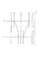
図3は、本発明の各実施例にかかるズームレンズの屈折力配分および広角端状態Wから望遠端状態Tへの焦点距離状態の変化における各レンズ群の移動の様子を示す図である。図3に示すように、本発明の各実施例にかかるズームレンズは、光軸に沿って物体側から順に、正の屈折力を有する第1レンズ群G1と、負の屈折力を有する第2レンズ群G2と、正の屈折力を有する第3レンズ群G3と、正の屈折力を有する第4レンズ群G4と、ローパスフィルターや赤外カットフィルター等からなるフィルター群FLとから構成されている。そして、広角端状態Wから望遠端状態Tへの焦点距離状態の変化(すなわちズーミング)に際して、第1レンズ群G1と、第3レンズ群G3は像面Iに対して固定で、第1レンズ群G1と第2レンズ群G2との間隔が増大し、第2レンズ群G2と第3レンズ群G3との間隔が減少し、第3レンズ群G3と第4レンズ群G4との間隔が減少する構成である。 FIG. 3 is a diagram illustrating the state of movement of each lens group in the refractive power distribution of the zoom lens according to each embodiment of the present invention and the change in the focal length state from the wide-angle end state W to the telephoto end state T. As shown in FIG. 3, the zoom lens according to each embodiment of the present invention includes a first lens group G1 having a positive refractive power and a second lens having a negative refractive power in order from the object side along the optical axis. The lens group G2 includes a third lens group G3 having a positive refractive power, a fourth lens group G4 having a positive refractive power, and a filter group FL including a low-pass filter and an infrared cut filter. . When the focal length state changes from the wide-angle end state W to the telephoto end state T (that is, zooming), the first lens group G1 and the third lens group G3 are fixed with respect to the image plane I, and the first lens group A configuration in which the distance between G1 and the second lens group G2 increases, the distance between the second lens group G2 and the third lens group G3 decreases, and the distance between the third lens group G3 and the fourth lens group G4 decreases. It is.
各実施例において、非球面は、光軸に垂直な方向の高さをyとし、高さyにおける各非球面の頂点の接平面から各非球面までの光軸に沿った距離(サグ量)をS(y)、基準球面の曲率半径(近軸曲率半径)をr、円錐定数をκ、n次の非球面係数をCnとしたとき、以下の数式で表される。
S(y)=(y2/r)/{1+(1−κ×y2/r2)1/2}
+C4×y4+C6×y6+C8×y8+C10×y10
In each embodiment, the height of the aspheric surface in the direction perpendicular to the optical axis is y, and the distance (sag amount) along the optical axis from the tangential plane of the apex of each aspheric surface to each aspheric surface at height y. Is S (y), the radius of curvature of the reference sphere (paraxial radius of curvature) is r, the conic constant is κ, and the nth-order aspherical coefficient is Cn, it is expressed by the following equation.
S (y) = (y 2 / r) / {1+ (1−κ × y 2 / r 2 ) 1/2 }
+ C4 × y 4 + C6 × y 6 + C8 × y 8 + C10 × y 10
なお、各実施例において、2次の非球面係数C2は0である。各実施例の表中において、非球面には面番号の左側に*印を付している。 In each embodiment, the secondary aspheric coefficient C2 is zero. In the table of each example, an aspherical surface is marked with * on the left side of the surface number.
(第1実施例)
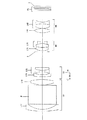
図4は、本発明の第1実施例にかかるズームレンズのレンズ構成を光軸に沿って展開して示す図である。
(First embodiment)
FIG. 4 is a diagram illustrating a lens configuration of the zoom lens according to the first embodiment of the present invention developed along the optical axis.
図4において、第1レンズ群G1は、光軸に沿って物体側から順に、物体側に凸面を向けた負メニスカスレンズL11と、光路を略90度折り曲げることを目的とした直角プリズムPと、物体側に非球面を備えた両凸形状の正レンズL12から構成されている。 In FIG. 4, the first lens group G1 includes, in order from the object side along the optical axis, a negative meniscus lens L11 having a convex surface facing the object side, a right-angle prism P intended to bend the optical path by approximately 90 degrees, It is composed of a biconvex positive lens L12 having an aspheric surface on the object side.
第2レンズ群G2は、光軸に沿って物体側から順に、像面I側に非球面を備え物体側に凸面を向けた負メニスカスレンズL21と、両凹形状の負レンズと物体側に凸面を向けた正メニスカスレンズとの貼り合わせからなる負の屈折力の接合レンズL22から構成されている。 The second lens group G2 includes, in order from the object side along the optical axis, a negative meniscus lens L21 having an aspheric surface on the image surface I side and a convex surface facing the object side, a biconcave negative lens, and a convex surface on the object side This is composed of a cemented lens L22 having a negative refractive power formed by bonding with a positive meniscus lens facing the lens.
第3レンズ群G3は、光軸に沿って物体側から順に、物体側に非球面を備えた両凸形状の正レンズL31と、両凸形状の正レンズと両凹形状の負レンズとの貼り合わせからなる負の屈折力の接合レンズL32で構成されている。 The third lens group G3 is formed by sticking, in order from the object side along the optical axis, a biconvex positive lens L31 having an aspheric surface on the object side, and a biconvex positive lens and a biconcave negative lens. It is composed of a cemented lens L32 having a negative refractive power made of a combination.
第4レンズ群G4は、光軸に沿って物体側から順に、像側に非球面を備えた両凸形状の正レンズL41と、両凸形状の正レンズと両凹形状の負レンズとの貼り合わせからなる負の屈折力の接合レンズL42で構成されている。 The fourth lens group G4 includes, in order from the object side along the optical axis, a biconvex positive lens L41 having an aspheric surface on the image side, and a bonding of a biconvex positive lens and a biconcave negative lens. It is composed of a cemented lens L42 having a negative refractive power made of a combination.
また、無限遠物体から近距離物体への焦点調節は、第2レンズ群G2を光軸に沿って物体側に移動することで行う。 Further, the focus adjustment from the object at infinity to the object at a short distance is performed by moving the second lens group G2 to the object side along the optical axis.
さらに、フィルター群FLは、ローパスフィルターや赤外カットフィルター等から構成されている。 Further, the filter group FL includes a low-pass filter, an infrared cut filter, and the like.
像面Iは、不図示の撮像素子上に形成され、該撮像素子はCCDやCMOS等から構成されている(以降の実施例についても同様である。)。 The image plane I is formed on an image pickup device (not shown), and the image pickup device is composed of a CCD, a CMOS, or the like (the same applies to the following embodiments).
また、開口絞りSは、第2レンズ群G2と第3レンズ群G3の間に配置され、広角端状態Wから望遠端状態Tへのズーミングに際して、像面Iに対して固定されている。 The aperture stop S is disposed between the second lens group G2 and the third lens group G3, and is fixed with respect to the image plane I during zooming from the wide-angle end state W to the telephoto end state T.
次の表1に、本第1実施例にかかるズームレンズの諸元の値を掲げる。表中の、「全体諸元」中のfは焦点距離を、F.NOはFナンバーを、2ωは画角(単位:度)を、Bfはバックフォーカスをそれぞれ表している。「レンズデータ」中の、面番号は光線の進行する方向に沿った物体側からのレンズ面の順序を、面間隔は各レンズ面の面間隔を、屈折率およびアッベ数はそれぞれd線(λ=587.6nm)に対する値を示している。尚、曲率半径0.0000は平面を示し、空気の屈折率1.00000は記載を省略してある。「非球面データ」中には、面番号、円錐係数κ、および各非球面係数C4〜C10の値をそれぞれ示す。「可変間隔データ」中には、焦点距離f、各可変間隔、およびバックフォーカスBfの値をそれぞれ示す。「条件式対応値」には、各条件式に対応する値をそれぞれ示す。 Table 1 below lists values of specifications of the zoom lens according to the first example. In the table, “f” in “Overall specifications” indicates the focal length, and F.F. NO represents the F number, 2ω represents the angle of view (unit: degree), and Bf represents the back focus. In the “lens data”, the surface number indicates the order of the lens surfaces from the object side along the direction in which the light beam travels, the surface interval indicates the surface interval of each lens surface, and the refractive index and Abbe number indicate the d-line (λ = 587.6 nm). The radius of curvature of 0.0000 indicates a plane, and the refractive index of air of 1.0000 is omitted. “Aspherical data” indicates the surface number, the conical coefficient κ, and the values of the aspherical coefficients C4 to C10. “Variable interval data” indicates the focal length f, each variable interval, and the value of the back focus Bf. The “conditional expression corresponding value” indicates a value corresponding to each conditional expression.
なお、以下の全ての諸元値において掲載されている焦点距離f、曲率半径r、面間隔d、その他長さの単位は一般に「mm」が使われるが、光学系は、比例拡大または比例縮小しても同等の光学性能が得られるので、これに限られるものではない。また、上記符号は、他の実施例でも同様であり説明を省略する。 In addition, the focal length f, the radius of curvature r, the surface interval d, and other length units listed in all the following specification values are generally “mm”, but the optical system is proportionally enlarged or reduced. However, the same optical performance can be obtained, and the present invention is not limited to this. The above reference numerals are the same in other embodiments, and the description thereof is omitted.
(表1)
「全体諸元」
広角端状態 中間焦点距離状態 望遠端状態
f = 6.49 〜 13.00 〜 18.35
F.NO = 3.23 〜 3.88 〜 4.36
2ω = 63.45 〜 31.73 〜 22.52
「レンズデータ」
面番号 曲率半径 面間隔 屈折率 アッベ数
1 25.0000 0.80 1.92286 18.90
2 10.1687 2.92
3 0.0000 8.00 1.83481 42.71
4 0.0000 0.20
* 5 16.5591 2.59 1.77377 47.18
6 -26.6813 (d6)
7 43.1399 1.00 1.80610 40.88
* 8 9.6052 1.42
9 -10.6311 0.70 1.78800 47.37
10 9.2523 1.54 1.92286 18.90
11 139.6780 (d11)
12 0.0000 0.50 (開口絞りS)
*13 7.9234 1.32 1.69350 53.20
14 -27.4529 0.20
15 11.7142 1.57 1.65160 58.55
16 -6.2105 0.70 1.83481 42.71
17 7.4146 (d17)
18 10.0252 1.55 1.58913 61.16
*19 -11.6786 0.10
20 6.5080 2.28 1.48749 70.23
21 -18.1248 0.75 1.79504 28.54
22 5.7167 (d22)
23 0.0000 0.65 1.54437 70.51
24 0.0000 0.40
25 0.0000 0.50 1.51633 64.14
26 0.0000 (Bf)
「非球面データ」
〔第5面〕
κ C4 C6 C8 C10
-1.4495 +4.2291×10⁻⁵ -1.2508×10⁻⁷ +3.0136×10⁻⁹ -4.1299×10⁻¹¹
〔第8面〕
κ C4 C6 C8 C10
-9.0000 +1.4000×10⁻³ -3.9508×10⁻⁵ +1.3308×10⁻⁶ -4.6579×10⁻⁹
〔第13面〕
κ C4 C6 C8 C10
+0.3527 +1.7586×10⁻⁵ +1.2242×10⁻⁵ -8.6518×10⁻⁷ +5.7865×10⁻⁸
〔第19面〕
κ C4 C6 C8 C10
+5.6263 +7.1091×10⁻⁴ +1.4030×10⁻⁵ -1.5418×10⁻⁷ +2.2411×10⁻⁸
「可変間隔データ」
広角端状態 中間焦点距離状態 望遠端状態
f 6.4900 13.0000 18.3500
d6 1.3806 6.0114 7.8333
d11 7.5027 2.8719 1.0500
d17 5.2220 2.5639 1.1150
d22 5.6760 8.3341 9.7830
Bf 0.5900 0.5900 0.5900
「条件式対応値」
(1)nd1=1.92286
(2)νd1=18.90
(3)f4/f3=0.74169
(4)ndp=1.83481
(5)(−f2)/fw=1.13206
(6)f1/(−f2)=2.65137
(Table 1)
"Overall specifications"
Wide-angle end state Intermediate focal length state Telephoto end state
f = 6.49 to 13.00 to 18.35
F.NO = 3.23 to 3.88 to 4.36
2ω = 63.45 to 31.73 to 22.52
"Lens data"
Surface number Curvature radius Surface spacing Refractive index Abbe number
1 25.0000 0.80 1.92286 18.90
2 10.1687 2.92
3 0.0000 8.00 1.83481 42.71
4 0.0000 0.20
* 5 16.5591 2.59 1.77377 47.18
6 -26.6813 (d6)
7 43.1399 1.00 1.80610 40.88
* 8 9.6052 1.42
9 -10.6311 0.70 1.78800 47.37
10 9.2523 1.54 1.92286 18.90
11 139.6780 (d11)
12 0.0000 0.50 (Aperture stop S)
* 13 7.9234 1.32 1.69350 53.20
14 -27.4529 0.20
15 11.7142 1.57 1.65160 58.55
16 -6.2105 0.70 1.83481 42.71
17 7.4146 (d17)
18 10.0252 1.55 1.58913 61.16
* 19 -11.6786 0.10
20 6.5080 2.28 1.48749 70.23
21 -18.1248 0.75 1.79504 28.54
22 5.7167 (d22)
23 0.0000 0.65 1.54437 70.51
24 0.0000 0.40
25 0.0000 0.50 1.51633 64.14
26 0.0000 (Bf)
"Aspherical data"
[Fifth side]
κ C4 C6 C8 C10
-1.4495 + 4.2291 × 10 -5 -1.2508 × 10 -7 + 3.0136 × 10 -9 -4.1299 × 10 -11
[Eighth side]
κ C4 C6 C8 C10
-9.0000 + 1.4000 × 10 -3 -3.9508 × 10 -5 + 1.3308 × 10 -6 -4.6579 × 10 -9
[13th page]
κ C4 C6 C8 C10
+0.3527 + 1.7586 × 10 -5 + 1.2242 × 10 -5 -8.6518 × 10 -7 + 5.7865 × 10 -8
[19th page]
κ C4 C6 C8 C10
+5.6263 + 7.1091 × 10 -4 + 1.4030 × 10 -5 -1.5418 × 10 -7 + 2.2411 × 10 -8
"Variable interval data"
Wide-angle end state Intermediate focal length state Telephoto end state
f 6.4900 13.0000 18.3500
d6 1.3806 6.0114 7.8333
d11 7.5027 2.8719 1.0500
d17 5.2220 2.5639 1.1150
d22 5.6760 8.3341 9.7830
Bf 0.5900 0.5900 0.5900
"Values for conditional expressions"
(1) nd1 = 1.92286
(2) νd1 = 18.90
(3) f4 / f3 = 0.74169
(4) ndp = 1.83481
(5) (−f2) /fw=1.13206
(6) f1 / (− f2) = 2.65137
図5は、本第1実施例にかかるズームレンズのd線(λ=587.6nm)に対する無限遠合焦状態における諸収差図であり、(a)は広角端状態(f=6.49mm)における諸収差図を、(b)は中間焦点距離状態(f=13.00mm)における諸収差を、(c)は望遠端状態(f=18.35mm)における諸収差をそれぞれ示す。 FIG. 5 is a diagram showing various aberrations in the infinitely focused state with respect to the d-line (λ = 587.6 nm) of the zoom lens according to the first example, and (a) is a wide-angle end state (f = 6.49 mm). (B) shows various aberrations in the intermediate focal length state (f = 13.00 mm), and (c) shows various aberrations in the telephoto end state (f = 18.35 mm).
各収差図において、FNOはFナンバーを、Aは半画角(単位:度)をそれぞれ示している。また、非点収差を示す収差図において実線はサジタル像面を示し、破線はメリディオナル像面を示している。さらに、球面収差を示す収差図において、実線は球面収差を示し、破線はサインコンディション(正弦条件)を示している。なお、上記符号は、その他の実施例も同様であり説明を省略する。 In each aberration diagram, FNO indicates an F number, and A indicates a half angle of view (unit: degree). In the aberration diagrams showing astigmatism, the solid line shows the sagittal image plane, and the broken line shows the meridional image plane. Further, in the aberration diagrams showing the spherical aberration, the solid line shows the spherical aberration, and the broken line shows the sine condition (sine condition). In addition, the said code | symbol is the same also in other Examples, and abbreviate | omits description.
各収差図から明らかなように、本第1実施例にかかるズームレンズは、広角端状態から望遠端状態までの各焦点距離状態において諸収差が良好に補正され、優れた結像性能を有することがわかる。 As is apparent from each aberration diagram, the zoom lens according to the first example has excellent imaging performance with various aberrations corrected well in each focal length state from the wide-angle end state to the telephoto end state. I understand.
(第2実施例)
図6は、本発明の第2実施例にかかるズームレンズのレンズ構成を光軸に沿って展開して示す図である。
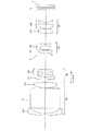
(Second embodiment)
FIG. 6 is a diagram illustrating a lens configuration of the zoom lens according to the second embodiment of the present invention developed along the optical axis.
図6において、第1レンズ群G1は、光軸に沿って物体側から順に、物体側に凸面を向けた負メニスカスレンズL11と、光路を略90度折り曲げることを目的とした直角プリズムPと、物体側に非球面を備えた両凸形状の正レンズL12から構成されている。 In FIG. 6, the first lens group G1 includes, in order from the object side along the optical axis, a negative meniscus lens L11 having a convex surface facing the object side, a right-angle prism P intended to bend the optical path by approximately 90 degrees, It is composed of a biconvex positive lens L12 having an aspheric surface on the object side.
第2レンズ群G2は、光軸に沿って物体側から順に、像面I側に非球面を備え物体側に凸面を向けた負メニスカスレンズL21と、両凹形状の負レンズと両凸形状の正レンズとの貼り合わせからなる負の屈折力の接合レンズL22から構成されている。 The second lens group G2 includes, in order from the object side along the optical axis, a negative meniscus lens L21 having an aspheric surface on the image plane I side and a convex surface facing the object side, a biconcave negative lens, and a biconvex shape It is composed of a cemented lens L22 having a negative refractive power formed by bonding with a positive lens.
第3レンズ群G3は、光軸に沿って物体側から順に、物体側に非球面を備えた両凸形状の正レンズL31と、両凸形状の正レンズと両凹形状の負レンズとの貼り合わせからなる負の屈折力の接合レンズL32で構成されている。 The third lens group G3 is formed by sticking, in order from the object side along the optical axis, a biconvex positive lens L31 having an aspheric surface on the object side, and a biconvex positive lens and a biconcave negative lens. It is composed of a cemented lens L32 having a negative refractive power made of a combination.
第4レンズ群G4は、光軸に沿って物体側から順に、像側に非球面を備えた両凸形状の正レンズL41と、両凸形状の正レンズと両凹形状の負レンズとの貼り合わせからなる負の屈折力の接合レンズL42で構成されている。 The fourth lens group G4 includes, in order from the object side along the optical axis, a biconvex positive lens L41 having an aspheric surface on the image side, and a bonding of a biconvex positive lens and a biconcave negative lens. It is composed of a cemented lens L42 having a negative refractive power made of a combination.
また、無限遠物体から近距離物体への焦点調節は、第2レンズ群G2を光軸に沿って物体側に移動することで行う。 Further, the focus adjustment from the object at infinity to the object at a short distance is performed by moving the second lens group G2 to the object side along the optical axis.
また、フィルター群FLは、ローパスフィルターや赤外カットフィルター等から構成されている。 The filter group FL includes a low-pass filter, an infrared cut filter, and the like.
また、開口絞りSは、第2レンズ群G2と第3レンズ群G3の間に配置され、広角端状態Wから望遠端状態Tへのズーミングに際して、像面Iに対して固定されている。 The aperture stop S is disposed between the second lens group G2 and the third lens group G3, and is fixed with respect to the image plane I during zooming from the wide-angle end state W to the telephoto end state T.
次の表2に、本第2実施例にかかるズームレンズの諸元の値を掲げる。 Table 2 below provides values of specifications of the zoom lens according to the second example.
(表2)
「全体諸元」
広角端状態 中間焦点距離状態 望遠端状態
f = 6.49 〜 12.42 〜 18.35
F.NO = 3.29 〜 3.89 〜 4.40
2ω = 63.45 〜 33.16 〜 22.52
「レンズデータ」
面番号 曲率半径 面間隔 屈折率 アッベ数
1 37.3815 0.80 1.92286 18.90
2 11.4743 2.50
3 0.0000 9.00 1.80420 46.50
4 0.0000 0.20
* 5 15.6194 2.52 1.77377 47.18
6 -26.0835 (d6)
7 33.9415 0.90 1.82080 42.71
* 8 8.3923 1.47
9 -9.3559 0.70 1.80400 46.57
10 10.5119 1.31 1.92286 18.90
11 -104.7189 (d11)
12 0.0000 0.50 (開口絞りS)
*13 7.2921 1.40 1.69350 53.20
14 -24.0200 0.15
15 12.7408 1.68 1.65160 58.55
16 -4.9883 0.70 1.83481 42.71
17 7.2495 (d17)
18 9.8677 1.86 1.58913 61.16
*19 -11.3223 0.10
20 7.1768 2.06 1.49700 81.54
21 -21.5501 0.80 1.79504 28.54
22 5.9728 (d22)
23 0.0000 0.65 1.54437 70.51
24 0.0000 0.40
25 0.0000 0.50 1.51633 64.14
26 0.0000 (Bf)
「非球面データ」
〔第5面〕
κ C4 C6 C8 C10
-1.2861 +2.7530×10⁻⁵ -1.9665×10⁻⁷ +6.3806×10⁻¹⁰ -1.9119×10⁻¹²
〔第8面〕
κ C4 C6 C8 C10
-9.0000 +2.0979×10⁻³ -9.3712×10⁻⁵ +4.3205×10⁻⁶ -6.7633×10⁻⁸
〔第13面〕
κ C4 C6 C8 C10
+0.4009 +7.1395×10⁻⁵ +1.4244×10⁻⁵ -4.5095×10⁻⁷ +6.1718×10⁻⁸
〔第19面〕
κ C4 C6 C8 C10
-9.0000 -4.4999×10⁻⁴ +3.2020×10⁻⁵ -1.0016×10⁻⁶ +1.0650×10⁻⁸
「可変間隔データ」
広角端状態 中間焦点距離状態 望遠端状態
f 6.4900 12.4200 18.3500
d6 1.3518 5.5097 7.5388
d11 7.2370 3.0791 1.0500
d17 5.2070 2.6787 1.1000
d22 5.8964 8.4247 10.0034
Bf 0.6000 0.6000 0.6000
「条件式対応値」
(1)nd1=1.92286
(2)νd1=18.90
(3)f4/f3=0.77620
(4)ndp=1.80420
(5)(−f2)/fw=1.08310
(6)f1/(−f2)=2.52762
(Table 2)
"Overall specifications"
Wide-angle end state Intermediate focal length state Telephoto end state
f = 6.49 to 12.42 to 18.35
F.NO = 3.29 to 3.89 to 4.40
2ω = 63.45 to 33.16 to 22.52
"Lens data"
Surface number Curvature radius Surface spacing Refractive index Abbe number
1 37.3815 0.80 1.92286 18.90
2 11.4743 2.50
3 0.0000 9.00 1.80420 46.50
4 0.0000 0.20
* 5 15.6194 2.52 1.77377 47.18
6 -26.0835 (d6)
7 33.9415 0.90 1.82080 42.71
* 8 8.3923 1.47
9 -9.3559 0.70 1.80400 46.57
10 10.5119 1.31 1.92286 18.90
11 -104.7189 (d11)
12 0.0000 0.50 (Aperture stop S)
* 13 7.2921 1.40 1.69350 53.20
14 -24.0200 0.15
15 12.7408 1.68 1.65160 58.55
16 -4.9883 0.70 1.83481 42.71
17 7.2495 (d17)
18 9.8677 1.86 1.58913 61.16
* 19 -11.3223 0.10
20 7.1768 2.06 1.49700 81.54
21 -21.5501 0.80 1.79504 28.54
22 5.9728 (d22)
23 0.0000 0.65 1.54437 70.51
24 0.0000 0.40
25 0.0000 0.50 1.51633 64.14
26 0.0000 (Bf)
"Aspherical data"
[Fifth side]
κ C4 C6 C8 C10
-1.2861 + 2.7530 × 10 -5 -1.9665 × 10 -7 + 6.3806 × 10 -10 -1.9119 × 10 -12
[Eighth side]
κ C4 C6 C8 C10
-9.0000 + 2.0979 × 10 -3 -9.3712 × 10 -5 + 4.3205 × 10 -6 -6.7633 × 10 -8
[13th page]
κ C4 C6 C8 C10
+0.4009 + 7.1395 × 10 -5 + 1.4244 × 10 -5 -4.5095 × 10 -7 + 6.1718 × 10 -8
[19th page]
κ C4 C6 C8 C10
-9.0000 -4.4999 × 10 -4 + 3.2020 × 10 -5 -1.0016 × 10 -6 + 1.0650 × 10 -8
"Variable interval data"
Wide-angle end state Intermediate focal length state Telephoto end state
f 6.4900 12.4200 18.3500
d6 1.3518 5.5097 7.5388
d11 7.2370 3.0791 1.0500
d17 5.2070 2.6787 1.1000
d22 5.8964 8.4247 10.0034
Bf 0.6000 0.6000 0.6000
"Values for conditional expressions"
(1) nd1 = 1.92286
(2) νd1 = 18.90
(3) f4 / f3 = 0.76620
(4) ndp = 1.80420
(5) (−f2) /fw=1.08310
(6) f1 / (− f2) = 2.52762
図7は、本第2実施例にかかるズームレンズのd線(λ=587.6nm)に対する無限遠合焦状態における諸収差図であり、(a)は、広角端状態(f=6.49mm)における諸収差図を、(b)は中間焦点距離状態(f=12.42mm)における諸収差を、(c)は望遠端状態(f=18.35mm)における諸収差をそれぞれ示す。 FIG. 7 is a diagram of various aberrations in the infinitely focused state with respect to the d-line (λ = 587.6 nm) of the zoom lens according to the second example, and (a) is a wide-angle end state (f = 6.49 mm). (B) shows various aberrations in the intermediate focal length state (f = 12.42 mm), and (c) shows various aberrations in the telephoto end state (f = 18.35 mm).
各収差図から明らかなように、本第2実施例にかかるズームレンズは、広角端状態から望遠端状態までの各焦点距離状態において諸収差が良好に補正され、優れた結像性能を有することがわかる。 As is apparent from each aberration diagram, the zoom lens according to the second example has excellent imaging performance with various aberrations corrected well in each focal length state from the wide-angle end state to the telephoto end state. I understand.
(第3実施例)
図8は、本発明の第3実施例にかかるズームレンズのレンズ構成を光軸に沿って展開して示す図である。
(Third embodiment)
FIG. 8 is a diagram illustrating a lens configuration of the zoom lens according to the third embodiment of the present invention developed along the optical axis.
図8において、第1レンズ群G1は、光軸に沿って物体側から順に、物体側に凸面を向けた負メニスカスレンズL11と、光路を略90度折り曲げることを目的とした直角プリズムPと、物体側に非球面を備えた両凸形状の正レンズL12から構成されている。 In FIG. 8, the first lens group G1 includes, in order from the object side along the optical axis, a negative meniscus lens L11 having a convex surface directed toward the object side, a right-angle prism P intended to bend the optical path by approximately 90 degrees, It is composed of a biconvex positive lens L12 having an aspheric surface on the object side.
第2レンズ群G2は、光軸に沿って物体側から順に、像面I側に非球面を備え物体側に凸面を向けた負メニスカスレンズL21と、両凹形状の負レンズと両凸形状の正レンズとの貼り合わせからなる負の屈折力の接合レンズL22から構成されている。 The second lens group G2 includes, in order from the object side along the optical axis, a negative meniscus lens L21 having an aspheric surface on the image plane I side and a convex surface facing the object side, a biconcave negative lens, and a biconvex shape It is composed of a cemented lens L22 having a negative refractive power formed by bonding with a positive lens.
第3レンズ群G3は、光軸に沿って物体側から順に、物体側に非球面を備えた両凸形状の正レンズL31と、両凸形状の正レンズと両凹形状の負レンズとの貼り合わせからなる負の屈折力の接合レンズL32で構成されている。 The third lens group G3 is formed by sticking, in order from the object side along the optical axis, a biconvex positive lens L31 having an aspheric surface on the object side, and a biconvex positive lens and a biconcave negative lens. It is composed of a cemented lens L32 having a negative refractive power made of a combination.
第4レンズ群G4は、光軸に沿って物体側から順に、像面I側に非球面を備えた両凸形状の正レンズL41、両凸形状の正レンズと両凹形状の負レンズとの貼り合わせからなる負の屈折力の接合レンズL42で構成されている。 The fourth lens group G4 includes, in order from the object side along the optical axis, a biconvex positive lens L41 having an aspheric surface on the image plane I side, a biconvex positive lens, and a biconcave negative lens. It is composed of a cemented lens L42 having a negative refractive power made by bonding.
また、無限遠物体から近距離物体への焦点調節は、第2レンズ群G2を光軸に沿って物体側に移動することで行う。 Further, the focus adjustment from the object at infinity to the object at a short distance is performed by moving the second lens group G2 to the object side along the optical axis.
また、フィルター群FLは、ローパスフィルターや赤外カットフィルター等から構成されている。 The filter group FL includes a low-pass filter, an infrared cut filter, and the like.
また、開口絞りSは、第2レンズ群G2と第3レンズ群G3の間に配置され、広角端状態Wから望遠端状態Tへのズーミングに際して、像面に対して固定されている。 The aperture stop S is disposed between the second lens group G2 and the third lens group G3, and is fixed with respect to the image plane during zooming from the wide-angle end state W to the telephoto end state T.
次の表3に、本第3実施例にかかるズームレンズの諸元の値を掲げる。 Table 3 below provides values of specifications of the zoom lens according to the third example.
(表3)
「全体諸元」
広角端状態 中間焦点距離状態 望遠端状態
f = 6.49 〜 12.42 〜 18.35
F.NO = 3.46 〜 4.03 〜 4.40
2ω = 63.45 〜 33.21 〜 22.52
「レンズデータ」
面番号 曲率半径 面間隔 屈折率 アッベ数
1 37.2624 0.90 1.92286 18.90
2 11.1482 2.45
3 0.0000 9.00 1.83481 42.71
4 0.0000 0.20
* 5 15.1979 2.57 1.77377 47.18
6 -25.3799 (d6)
7 41.2336 0.90 1.82080 42.71
* 8 8.4256 1.50
9 -9.2831 0.70 1.78800 47.37
10 12.0522 1.30 1.92286 18.90
11 -68.6250 (d11)
12 0.0000 0.50 (開口絞りS)
*13 7.6045 1.45 1.69350 53.20
14 -34.1354 0.15
15 10.6131 1.87 1.65160 58.55
16 -5.3841 0.70 1.83481 42.71
17 7.0835 (d17)
18 10.0717 1.99 1.58913 61.16
*19 -10.9249 0.10
20 7.5031 2.19 1.48749 70.23
21 -11.3937 0.80 1.79504 28.54
22 6.7316 (d22)
23 0.0000 0.65 1.54437 70.51
24 0.0000 0.40
25 0.0000 0.50 1.51633 64.14
26 0.0000 (Bf)
「非球面データ」
〔第5面〕
κ C4 C6 C8 C10
-5.8159 +1.8991×10⁻⁴ -2.5581×10⁻⁶ +2.9511×10⁻⁸ -2.0089×10⁻¹⁰
〔第8面〕
κ C4 C6 C8 C10
-9.0000 +2.0520×10⁻³ -8.7500×10⁻⁵ +3.6741×10⁻⁶ -4.7536×10⁻⁸
〔第13面〕
κ C4 C6 C8 C10
+0.4028 +8.0510×10⁻⁵ +1.5444×10⁻⁵ -9.1869×10⁻⁷ +7.2852×10⁻⁸
〔第19面〕
κ C4 C6 C8 C10
-9.0000 -5.8178×10⁻⁴ +3.4645×10⁻⁵ -1.1500×10⁻⁶ +1.5550×10⁻⁸
「可変間隔データ」
広角端状態 中間焦点距離状態 望遠端状態
f 6.4900 12.4200 18.3500
d6 1.3774 5.6717 7.9738
d11 7.6464 3.3521 1.0500
d17 4.4527 2.2134 1.1000
d22 5.6029 7.8422 8.9556
Bf 0.5999 0.6000 0.6000
「条件式対応値」
(1)nd1=1.92286
(2)νd1=18.90
(3)f4/f3=0.79595
(4)ndp=1.83481
(5)(−f2)/fw=1.10029
(6)f1/(−f2)=2.42205
(Table 3)
"Overall specifications"
Wide-angle end state Intermediate focal length state Telephoto end state
f = 6.49 to 12.42 to 18.35
F.NO = 3.46 to 4.03 to 4.40
2ω = 63.45 to 33.21 to 22.52
"Lens data"
Surface number Curvature radius Surface spacing Refractive index Abbe number
1 37.2624 0.90 1.92286 18.90
2 11.1482 2.45
3 0.0000 9.00 1.83481 42.71
4 0.0000 0.20
* 5 15.1979 2.57 1.77377 47.18
6 -25.3799 (d6)
7 41.2336 0.90 1.82080 42.71
* 8 8.4256 1.50
9 -9.2831 0.70 1.78800 47.37
10 12.0522 1.30 1.92286 18.90
11 -68.6250 (d11)
12 0.0000 0.50 (Aperture stop S)
* 13 7.6045 1.45 1.69350 53.20
14 -34.1354 0.15
15 10.6131 1.87 1.65160 58.55
16 -5.3841 0.70 1.83481 42.71
17 7.0835 (d17)
18 10.0717 1.99 1.58913 61.16
* 19 -10.9249 0.10
20 7.5031 2.19 1.48749 70.23
21 -11.3937 0.80 1.79504 28.54
22 6.7316 (d22)
23 0.0000 0.65 1.54437 70.51
24 0.0000 0.40
25 0.0000 0.50 1.51633 64.14
26 0.0000 (Bf)
"Aspherical data"
[Fifth side]
κ C4 C6 C8 C10
-5.8159 + 1.8991 × 10 -4 -2.5581 × 10 -6 + 2.9511 × 10 -8 -2.0089 × 10 -10
[Eighth side]
κ C4 C6 C8 C10
-9.0000 + 2.0520 × 10 -3 -8.7500 × 10 -5 + 3.6741 × 10 -6 -4.7536 × 10 -8
[13th page]
κ C4 C6 C8 C10
+0.4028 +8.0 510 × 10 -5 + 1.5444 × 10 -5 -9.1869 × 10 -7 + 7.2852 × 10 -8
[19th page]
κ C4 C6 C8 C10
-9.0000 -5.8178 × 10 -4 + 3.4645 × 10 -5 -1.1500 × 10 -6 + 1.5550 × 10 -8
"Variable interval data"
Wide-angle end state Intermediate focal length state Telephoto end state
f 6.4900 12.4200 18.3500
d6 1.3774 5.6717 7.9738
d11 7.6464 3.3521 1.0500
d17 4.4527 2.2134 1.1000
d22 5.6029 7.8422 8.9556
Bf 0.5999 0.6000 0.6000
"Values for conditional expressions"
(1) nd1 = 1.92286
(2) νd1 = 18.90
(3) f4 / f3 = 0.79595
(4) ndp = 1.83481
(5) (−f2) /fw=1.10029
(6) f1 / (− f2) = 2.422205
図9は、本第3実施例にかかるズームレンズのd線(λ=587.6nm)に対する無限遠合焦状態における諸収差図であり、(a)は広角端状態(f=6.49mm)における諸収差図を、(b)は中間焦点距離状態(f=12.42mm)における諸収差を、(c)は望遠端状態(f=18.35mm)における諸収差をそれぞれ示す。 FIG. 9 is a diagram showing various aberrations of the zoom lens according to the third example in the infinite focus state with respect to the d-line (λ = 587.6 nm). FIG. 9A is a wide-angle end state (f = 6.49 mm). (B) shows various aberrations in the intermediate focal length state (f = 12.42 mm), and (c) shows various aberrations in the telephoto end state (f = 18.35 mm).
各収差図から明らかなように、本第3実施例にかかるズームレンズは、広角端状態から望遠端状態までの各焦点距離状態において諸収差が良好に補正され、優れた結像性能を有することがわかる。 As is apparent from each aberration diagram, the zoom lens according to the third example has excellent imaging performance with various aberrations corrected well in each focal length state from the wide-angle end state to the telephoto end state. I understand.
(第4実施例)
図10は、本発明の第4実施例にかかるズームレンズのレンズ構成を光軸に沿って展開して示す図である。
(Fourth embodiment)
FIG. 10 is a diagram illustrating a lens configuration of the zoom lens according to the fourth example of the present invention developed along the optical axis.
図10において、第1レンズ群G1は、光軸に沿って物体側から順に、物体側に凸面を向けた負メニスカスレンズL11と、光路を略90度折り曲げることを目的とした直角プリズムPと、物体側に非球面を備えた両凸形状の正レンズL12から構成されている。 In FIG. 10, the first lens group G1 includes, in order from the object side along the optical axis, a negative meniscus lens L11 having a convex surface facing the object side, a right-angle prism P intended to bend the optical path by approximately 90 degrees, It is composed of a biconvex positive lens L12 having an aspheric surface on the object side.
第2レンズ群G2は、光軸に沿って物体側から順に、像面I側に非球面を備えた両凹形状の負レンズL21と、両凹形状の負レンズと両凸形状の正レンズとの貼り合わせからなる負の屈折力の接合レンズL22から構成されている。 The second lens group G2 includes, in order from the object side along the optical axis, a biconcave negative lens L21 having an aspheric surface on the image plane I side, a biconcave negative lens, and a biconvex positive lens. This is composed of a cemented lens L22 having a negative refractive power made up of these two lenses.
第3レンズ群G3は、光軸に沿って物体側から順に、物体側に非球面を備えた両凸形状の正レンズL31と、両凸形状の正レンズと両凹形状の負レンズとの貼り合わせからなる負の屈折力の接合レンズL32で構成されている。 The third lens group G3 is formed by sticking, in order from the object side along the optical axis, a biconvex positive lens L31 having an aspheric surface on the object side, and a biconvex positive lens and a biconcave negative lens. It is composed of a cemented lens L32 having a negative refractive power made of a combination.
第4レンズ群G4は、光軸に沿って物体側から順に、像面I側に非球面を備えた両凸形状の正レンズL41と、両凸形状の正レンズと両凹形状の負レンズとの貼り合わせからなる負の屈折力の接合レンズL42で構成されている。 The fourth lens group G4 includes, in order from the object side along the optical axis, a biconvex positive lens L41 having an aspheric surface on the image plane I side, a biconvex positive lens, and a biconcave negative lens. This is composed of a cemented lens L42 having a negative refractive power, which is formed by bonding together.
また、無限遠物体から近距離物体への焦点調節は、第2レンズ群G2を光軸に沿って物体側に移動することで行う。 Further, the focus adjustment from the object at infinity to the object at a short distance is performed by moving the second lens group G2 to the object side along the optical axis.
また、フィルター群FLは、ローパスフィルターや赤外カットフィルター等から構成されている。 The filter group FL includes a low-pass filter, an infrared cut filter, and the like.
また、開口絞りSは、第2レンズ群G2と第3レンズ群G3の間に配置され、広角端状態Wから望遠端状態Tへのズーミングに際して、像面Iに対して固定されている。 The aperture stop S is disposed between the second lens group G2 and the third lens group G3, and is fixed with respect to the image plane I during zooming from the wide-angle end state W to the telephoto end state T.
次の表4に、本第4実施例にかかるズームレンズの諸元の値を掲げる。 Table 4 below provides values of specifications of the zoom lens according to the fourth example.
(表4)
「全体諸元」
広角端状態 中間焦点距離状態 望遠端状態
f = 6.49 〜 12.42 〜 18.35
F.NO = 3.46 〜 4.04 〜 4.41
2ω = 63.44 〜 33.20 〜 22.52
「レンズデータ」
面番号 曲率半径 面間隔 屈折率 アッベ数
1 33.7718 0.80 1.94595 17.98
2 11.7461 2.50
3 0.0000 9.00 1.83481 42.71
4 0.0000 0.20
* 5 13.9344 2.60 1.77377 47.18
6 -27.5986 (d6)
7 -61.3807 0.90 1.82080 42.71
* 8 8.9234 1.40
9 -12.0258 0.80 1.81600 46.62
10 11.6524 1.35 1.94595 17.98
11 -97.7336 (d11)
12 0.0000 0.50 (開口絞りS)
*13 7.7058 1.50 1.68863 52.85
14 -25.9720 0.15
15 13.8124 1.90 1.65160 58.55
16 -4.5044 0.80 1.83481 42.71
17 9.1795 (d17)
18 10.2475 2.15 1.58913 61.16
*19 -10.8582 0.10
20 6.9779 2.15 1.48749 70.23
21 -13.5284 0.80 1.79504 28.54
22 5.9758 (d22)
23 0.0000 0.65 1.54437 70.51
24 0.0000 0.40
25 0.0000 0.50 1.51633 64.14
26 0.0000 (Bf)
「非球面データ」
〔第5面〕
κ C4 C6 C8 C10
-1.5628 +5.9482×10⁻⁵ -5.0922×10⁻⁷ +3.3737×10⁻⁹ -3.2731×10⁻¹¹
〔第8面〕
κ C4 C6 C8 C10
-9.0000 +1.6926×10⁻³ -5.7910×10⁻⁵ +6.6386×10⁻⁷ +9.8033×10⁻⁸
〔第13面〕
κ C4 C6 C8 C10
+0.4479 +1.1451×10⁻⁴ +2.1327×10⁻⁵ -1.1862×10⁻⁶ +1.2675×10⁻⁷
〔第19面〕
κ C4 C6 C8 C10
-9.0000 -5.6183×10⁻⁴ +3.8657×10⁻⁵ -1.1222×10⁻⁶ +2.5253×10⁻⁹
「可変間隔データ」
広角端状態 中間焦点距離状態 望遠端状態
f 6.4900 12.4198 18.3496
d6 1.3281 5.1577 7.2028
d11 6.9247 3.0950 1.0500
d17 4.7633 2.4074 1.2377
d22 5.7268 8.0827 9.2525
Bf 0.5998 0.5997 0.5997
「条件式対応値」
(1)nd1=1.94595
(2)νd1=17.98
(3)f4/f3=0.85941
(4)ndp=1.83481
(5)(−f2)/fw=0.97891
(6)f1/(−f2)=2.50823
(Table 4)
"Overall specifications"
Wide-angle end state Intermediate focal length state Telephoto end state
f = 6.49 to 12.42 to 18.35
F.NO = 3.46 to 4.04 to 4.41
2ω = 63.44 to 33.20 to 22.52
"Lens data"
Surface number Curvature radius Surface spacing Refractive index Abbe number
1 33.7718 0.80 1.94595 17.98
2 11.7461 2.50
3 0.0000 9.00 1.83481 42.71
4 0.0000 0.20
* 5 13.9344 2.60 1.77377 47.18
6 -27.5986 (d6)
7 -61.3807 0.90 1.82080 42.71
* 8 8.9234 1.40
9 -12.0258 0.80 1.81600 46.62
10 11.6524 1.35 1.94595 17.98
11 -97.7336 (d11)
12 0.0000 0.50 (Aperture stop S)
* 13 7.7058 1.50 1.68863 52.85
14 -25.9720 0.15
15 13.8124 1.90 1.65160 58.55
16 -4.5044 0.80 1.83481 42.71
17 9.1795 (d17)
18 10.2475 2.15 1.58913 61.16
* 19 -10.8582 0.10
20 6.9779 2.15 1.48749 70.23
21 -13.5284 0.80 1.79504 28.54
22 5.9758 (d22)
23 0.0000 0.65 1.54437 70.51
24 0.0000 0.40
25 0.0000 0.50 1.51633 64.14
26 0.0000 (Bf)
"Aspherical data"
[Fifth side]
κ C4 C6 C8 C10
-1.5628 + 5.9482 × 10 -5 -5.0922 × 10 -7 + 3.3737 × 10 -9 -3.2731 × 10 -11
[Eighth side]
κ C4 C6 C8 C10
-9.0000 + 1.6926 × 10 -3 -5.7910 × 10 -5 + 6.6386 × 10 -7 + 9.8033 × 10 -8
[13th page]
κ C4 C6 C8 C10
+0.4479 + 1.1451 × 10 -4 + 2.1327 × 10 -5 -1.1862 × 10 -6 + 1.2675 × 10 -7
[19th page]
κ C4 C6 C8 C10
-9.0000 -5.6183 × 10 -4 + 3.8657 × 10 -5 -1.1222 × 10 -6 + 2.5253 × 10 -9
"Variable interval data"
Wide-angle end state Intermediate focal length state Telephoto end state
f 6.4900 12.4198 18.3496
d6 1.3281 5.1577 7.2028
d11 6.9247 3.0950 1.0500
d17 4.7633 2.4074 1.2377
d22 5.7268 8.0827 9.2525
Bf 0.5998 0.5997 0.5997
"Values for conditional expressions"
(1) nd1 = 1.94595
(2) νd1 = 17.98
(3) f4 / f3 = 0.85941
(4) ndp = 1.83481
(5) (−f2) /fw=0.97891
(6) f1 / (− f2) = 2.5823
図11は、本第4実施例にかかるズームレンズのd線(λ=587.6nm)に対する無限遠合焦状態における諸収差図であり、(a)は広角端状態(f=6.49mm)における諸収差図を、(b)は中間焦点距離状態(f=12.42mm)における諸収差を、(c)は望遠端状態(f=18.35mm)における諸収差をそれぞれ示す。 FIG. 11 is a diagram illustrating various aberrations in the infinitely focused state with respect to the d-line (λ = 587.6 nm) of the zoom lens according to the fourth example, and (a) is a wide-angle end state (f = 6.49 mm). (B) shows various aberrations in the intermediate focal length state (f = 12.42 mm), and (c) shows various aberrations in the telephoto end state (f = 18.35 mm).
各収差図から明らかなように、本第4実施例にかかるズームレンズは、広角端状態から望遠端状態までの各焦点距離状態において諸収差が良好に補正され、優れた結像性能を有することがわかる。 As is apparent from each aberration diagram, the zoom lens according to the fourth example has excellent imaging performance with various aberrations corrected well in each focal length state from the wide-angle end state to the telephoto end state. I understand.
(第5実施例)
図12は、第5実施例にかかるズームレンズのレンズ構成を光軸に沿って展開して示す図である。
(5th Example)
FIG. 12 is a diagram illustrating a lens configuration of the zoom lens according to the fifth example developed along the optical axis.
図12において、第1レンズ群G1は、光軸に沿って物体側から順に、物体側に凸面を向けた負メニスカスレンズL11と、光路を略90度折り曲げることを目的とした直角プリズムPと、物体側に非球面を備えた両凸形状の正レンズL12から構成されている。 In FIG. 12, the first lens group G1 includes, in order from the object side along the optical axis, a negative meniscus lens L11 having a convex surface directed toward the object side, and a right-angle prism P intended to bend the optical path by approximately 90 degrees. It is composed of a biconvex positive lens L12 having an aspheric surface on the object side.
第2レンズ群G2は、光軸に沿って物体側から順に、物体側に凸面を向け像面I側に非球面を備えた負メニスカスレンズL21と、両凹形状の負レンズと物体側に凸面を向けた正メニスカスレンズとの貼り合わせからなる負の屈折力の接合レンズL22から構成されている。 The second lens group G2 includes, in order from the object side along the optical axis, a negative meniscus lens L21 having a convex surface facing the object side and an aspheric surface on the image surface I side, a biconcave negative lens, and a convex surface facing the object side. This is composed of a cemented lens L22 having a negative refractive power formed by bonding with a positive meniscus lens facing the lens.
第3レンズ群G3は、光軸に沿って物体側から順に、物体側に非球面を備えた両凸形状の正レンズL31と、両凸形状の正レンズと両凹形状の負レンズとの貼り合わせからなる負の屈折力の接合レンズL32で構成されている。 The third lens group G3 is formed by sticking, in order from the object side along the optical axis, a biconvex positive lens L31 having an aspheric surface on the object side, and a biconvex positive lens and a biconcave negative lens. It is composed of a cemented lens L32 having a negative refractive power made of a combination.
第4レンズ群G4は、光軸に沿って物体側から順に、像面I側に非球面を備えた両凸形状の正レンズL41と、両凸形状の正レンズと両凹形状の負レンズとの貼り合わせからなる負の屈折力の接合レンズL42で構成されている。 The fourth lens group G4 includes, in order from the object side along the optical axis, a biconvex positive lens L41 having an aspheric surface on the image plane I side, a biconvex positive lens, and a biconcave negative lens. This is composed of a cemented lens L42 having a negative refractive power, which is formed by bonding together.
また、無限遠物体から近距離物体への焦点調節は、第2レンズ群G2を光軸に沿って物体側に移動することで行う。 Further, the focus adjustment from the object at infinity to the object at a short distance is performed by moving the second lens group G2 to the object side along the optical axis.
また、フィルター群FLは、ローパスフィルターや赤外カットフィルター等から構成されている。 The filter group FL includes a low-pass filter, an infrared cut filter, and the like.
また、開口絞りSは、第3レンズ群G3の最も物体側に配置され、広角端状態から望遠端状態へのズーミングに際して、像面Iに対して固定である。 The aperture stop S is disposed closest to the object side of the third lens group G3, and is fixed with respect to the image plane I during zooming from the wide-angle end state to the telephoto end state.
次の表5に、本第5実施例にかかるズームレンズの諸元の値を掲げる。 Table 5 below provides values of specifications of the zoom lens according to the fifth example.
(表5)
「全体諸元」
広角端状態 中間焦点距離状態 望遠端状態
f = 6.49 〜 13.00 〜 18.35
F.NO = 3.25 〜 3.92 〜 4.44
2ω = 63.46 〜 31.68 〜 22.52
「レンズデータ」
面番号 曲率半径 面間隔 屈折率 アッベ数
1 30.0000 0.80 1.92286 18.90
2 10.8266 2.76
3 0.0000 10.50 1.88300 40.76
4 0.0000 0.20
* 5 17.6854 2.54 1.77377 47.18
6 -24.9579 (d6)
7 49.4226 1.00 1.80610 40.88
* 8 10.1943 1.32
9 -11.0741 0.70 1.77250 49.60
10 8.9104 1.40 1.92286 18.90
11 66.6471 (d11)
12 0.0000 0.50 (開口絞りS)
*13 8.0543 1.33 1.69350 53.20
14 -23.6288 0.10
15 14.5229 1.55 1.65160 58.55
16 -5.8631 0.70 1.83481 42.71
17 8.2446 (d17)
18 9.6258 2.04 1.58913 61.16
*19 -11.5184 0.10
20 6.9573 2.15 1.48749 70.23
21 -18.4789 0.80 1.79504 28.54
22 5.7682 (d22)
23 0.0000 0.65 1.54437 70.51
24 0.0000 0.40
25 0.0000 0.50 1.51633 64.14
26 0.0000 (Bf)
「非球面データ」
〔第5面〕
κ C4 C6 C8 C10
-1.8966 +3.3740×10⁻⁵ -2.5195×10⁻⁷ +2.9256×10⁻⁹ -2.3805×10⁻¹¹
〔第8面〕
κ C4 C6 C8 C10
-8.9802 +1.2224×10⁻³ -3.6939×10⁻⁵ +1.5818×10⁻⁶ -1.8716×10⁻⁸
〔第13面〕
κ C4 C6 C8 C10
+0.3629 +2.1443×10⁻⁵ +9.5031×10⁻⁶ -4.2244×10⁻⁷ +3.9902×10⁻⁸
〔第19面〕
κ C4 C6 C8 C10
+5.7565 +7.8405×10⁻⁴ +1.7280×10⁻⁵ -2.5355×10⁻⁷ +2.9997×10⁻⁸
「可変間隔データ」
広角端状態 中間焦点距離状態 望遠端状態
f 6.4900 12.9997 18.3499
d6 1.3662 5.9198 7.7019
d11 7.3857 2.8321 1.0500
d17 5.4454 2.6465 1.1000
d22 6.1696 8.9684 10.5150
Bf 0.5900 0.5900 0.5900
「条件式対応値」
(1)nd1=1.92286
(2)νd1=18.90
(3)f4/f3=0.71550
(4)ndp=1.88300
(5)(−f2)/fw=1.14409
(6)f1/(−f2)=2.49132
(Table 5)
"Overall specifications"
Wide-angle end state Intermediate focal length state Telephoto end state
f = 6.49 to 13.00 to 18.35
F.NO = 3.25 to 3.92 to 4.44
2ω = 63.46 to 31.68 to 22.52
"Lens data"
Surface number Curvature radius Surface spacing Refractive index Abbe number
1 30.0000 0.80 1.92286 18.90
2 10.8266 2.76
3 0.0000 10.50 1.88300 40.76
4 0.0000 0.20
* 5 17.6854 2.54 1.77377 47.18
6 -24.9579 (d6)
7 49.4226 1.00 1.80610 40.88
* 8 10.1943 1.32
9 -11.0741 0.70 1.77250 49.60
10 8.9104 1.40 1.92286 18.90
11 66.6471 (d11)
12 0.0000 0.50 (Aperture stop S)
* 13 8.0543 1.33 1.69350 53.20
14 -23.6288 0.10
15 14.5229 1.55 1.65160 58.55
16 -5.8631 0.70 1.83481 42.71
17 8.2446 (d17)
18 9.6258 2.04 1.58913 61.16
* 19 -11.5184 0.10
20 6.9573 2.15 1.48749 70.23
21 -18.4789 0.80 1.79504 28.54
22 5.7682 (d22)
23 0.0000 0.65 1.54437 70.51
24 0.0000 0.40
25 0.0000 0.50 1.51633 64.14
26 0.0000 (Bf)
"Aspherical data"
[Fifth side]
κ C4 C6 C8 C10
-1.8966 + 3.3740 × 10 -5 -2.5195 × 10 -7 + 2.9256 × 10 -9 -2.3805 × 10 -11
[Eighth side]
κ C4 C6 C8 C10
-8.9802 + 1.2224 × 10 -3 -3.6939 × 10 -5 + 1.5818 × 10 -6 -1.8716 × 10 -8
[13th page]
κ C4 C6 C8 C10
+0.3629 + 2.1443 × 10 -5 + 9.5031 × 10 -6 -4.2244 × 10 -7 + 3.9902 × 10 -8
[19th page]
κ C4 C6 C8 C10
+5.7565 + 7.8405 × 10 -4 + 1.7280 × 10 -5 -2.5355 × 10 -7 + 2.9997 × 10 -8
"Variable interval data"
Wide-angle end state Intermediate focal length state Telephoto end state
f 6.4900 12.9997 18.3499
d6 1.3662 5.9198 7.7019
d11 7.3857 2.8321 1.0500
d17 5.4454 2.6465 1.1000
d22 6.1696 8.9684 10.5150
Bf 0.5900 0.5900 0.5900
"Values for conditional expressions"
(1) nd1 = 1.92286
(2) νd1 = 18.90
(3) f4 / f3 = 0.71550
(4) ndp = 1.88300
(5) (−f2) /fw=1.14409
(6) f1 / (− f2) = 2.49132
図13〜図15は、本第5実施例にかかるズームレンズのd線(λ=587.6nm)に対する無限遠合焦状態における諸収差図であり、図13は広角端状態(f=6.49mm)における諸収差を、図14は中間焦点距離状態(f=13.00mm)における諸収差を、図15は望遠端状態(f=18.35mm)における諸収差をそれぞれ示す。 FIGS. 13 to 15 are graphs showing various aberrations of the zoom lens according to the fifth example in the infinite focus state with respect to the d-line (λ = 587.6 nm), and FIG. 13 shows the wide-angle end state (f = 6. 49 shows various aberrations in the intermediate focal length state (f = 13.00 mm), and FIG. 15 shows various aberrations in the telephoto end state (f = 18.35 mm).
各収差図から明らかなように、本第5実施例にかかるズームレンズは、広角端状態から望遠端状態までの各焦点距離状態において諸収差が良好に補正され、優れた結像性能を有することがわかる。 As is apparent from each aberration diagram, the zoom lens according to the fifth example has excellent imaging performance with various aberrations corrected well in each focal length state from the wide-angle end state to the telephoto end state. I understand.
(第6実施例)
図16は、第6実施例にかかるズームレンズのレンズ構成を光軸に沿って展開して示す図である。
(Sixth embodiment)
FIG. 16 is a diagram illustrating a lens configuration of the zoom lens according to the sixth example developed along the optical axis.
図16において、第1レンズ群G1は、光軸に沿って物体側から順に、物体側に凸面を向けた負メニスカスレンズL11と、光路を略90度折り曲げることを目的とした直角プリズムPと、物体側に非球面を備えた両凸形状の正レンズL12から構成されている。 In FIG. 16, the first lens group G1 includes, in order from the object side along the optical axis, a negative meniscus lens L11 having a convex surface facing the object side, a right-angle prism P intended to bend the optical path by approximately 90 degrees, It is composed of a biconvex positive lens L12 having an aspheric surface on the object side.
第2レンズ群G2は、光軸に沿って物体側から順に、物体側に凸面を向け像面I側に非球面を備えた負メニスカスレンズL21と、両凹形状の負レンズと両凸形状の正レンズとの貼り合わせからなる負の屈折力の接合レンズL22から構成されている。 The second lens group G2 includes, in order from the object side along the optical axis, a negative meniscus lens L21 having a convex surface on the object side and an aspheric surface on the image plane I side, a biconcave negative lens, and a biconvex shape. It is composed of a cemented lens L22 having a negative refractive power formed by bonding with a positive lens.
第3レンズ群G3は、光軸に沿って物体側から順に、物体側に非球面を備えた両凸形状の正レンズL31と、両凸形状の正レンズと両凹形状の負レンズとの貼り合わせからなる負の屈折力の接合レンズL32で構成されている。 The third lens group G3 is formed by sticking, in order from the object side along the optical axis, a biconvex positive lens L31 having an aspheric surface on the object side, and a biconvex positive lens and a biconcave negative lens. It is composed of a cemented lens L32 having a negative refractive power made of a combination.
第4レンズ群G4は、光軸に沿って物体側から順に、像側に非球面を備えた両凸形状の正レンズL41と、両凸形状の正レンズと両凹形状の負レンズとの貼り合わせからなる負の屈折力の接合レンズL42で構成されている。 The fourth lens group G4 includes, in order from the object side along the optical axis, a biconvex positive lens L41 having an aspheric surface on the image side, and a bonding of a biconvex positive lens and a biconcave negative lens. It is composed of a cemented lens L42 having a negative refractive power made of a combination.
また、無限遠物体から近距離物体への焦点調節は、第2レンズ群G2を光軸に沿って物体側に移動することで行う。 Further, the focus adjustment from the object at infinity to the object at a short distance is performed by moving the second lens group G2 to the object side along the optical axis.
また、フィルター群FLは、ローパスフィルターや赤外カットフィルター等から構成されている。 The filter group FL includes a low-pass filter, an infrared cut filter, and the like.
また、開口絞りSは、第3レンズ群G3の最も物体側に配置され、広角端状態から望遠端状態へのズーミングに際して、像面Iに対して固定である。 The aperture stop S is disposed closest to the object side of the third lens group G3, and is fixed with respect to the image plane I during zooming from the wide-angle end state to the telephoto end state.
次の表6に、本第6実施例にかかるズームレンズの諸元の値を掲げる。 Table 6 below provides values of specifications of the zoom lens according to the sixth example.
(表6)
「全体諸元」
広角端状態 中間焦点距離状態 望遠端状態
f = 6.49 〜 13.00 〜 18.35
F.NO = 3.28 〜 3.89 〜 4.40
2ω = 63.45 〜 33.20 〜 22.52
「レンズデータ」
面番号 曲率半径 面間隔 屈折率 アッベ数
1 24.5000 0.80 1.92286 18.90
2 9.9772 2.95
3 0.0000 8.50 1.83481 42.71
4 0.0000 0.20
* 5 16.6000 2.63 1.77377 47.18
6 -24.8401 (d6)
7 74.7674 1.00 1.82080 42.71
* 8 9.4961 1.39
9 -10.0785 0.70 1.78800 47.37
10 11.0108 1.35 1.92286 18.90
11 -140.1574 (d11)
12 0.0000 0.50 (開口絞りS)
*13 7.2743 1.39 1.69350 53.20
14 -26.2141 0.15
15 13.0403 1.59 1.65160 58.55
16 -5.7472 0.70 1.83481 42.71
17 7.0000 (d17)
18 9.8799 1.69 1.58913 61.16
*19 -11.2538 0.10
20 6.8394 2.19 1.48749 70.23
21 -15.4997 0.80 1.79504 28.54
22 6.0883 (d22)
23 0.0000 0.65 1.54437 70.51
24 0.0000 0.40
25 0.0000 0.50 1.51633 64.14
26 0.0000 (Bf)
「非球面データ」
〔第5面〕
κ C4 C6 C8 C10
-1.5215 +3.9133×10⁻⁵ -1.9315×10⁻⁷ +3.1162×10⁻⁹ -3.5747×10⁻¹¹
〔第8面〕
κ C4 C6 C8 C10
-9.0000 +1.4631×10⁻³ -4.9164×10⁻⁵ +2.1048×10⁻⁶ -2.6229×10⁻⁸
〔第13面〕
κ C4 C6 C8 C10
+0.3110 +4.3394×10⁻⁵ +1.0663×10⁻⁵ -4.6198×10⁻⁷ +4.5396×10⁻⁸
〔第19面〕
κ C4 C6 C8 C10
-1.7610 +1.0693×10⁻⁴ +6.5769×10⁻⁶ -2.4528×10⁻⁷ +8.6823×10⁻¹⁰
「可変間隔データ」
広角端状態 中間焦点距離状態 望遠端状態
f 6.4900 12.4200 18.3500
d6 1.3733 5.6158 7.7020
d11 7.3787 3.1362 1.0500
d17 5.0253 2.6114 1.1000
d22 5.9477 8.3616 9.8730
Bf 0.6000 0.6000 0.6000
「条件式対応値」
(1)nd1=1.92286
(2)νd1=18.90
(3)f4/f3=0.70338
(4)ndp=1.83481
(5)(−f2)/fw=1.11448
(6)f1/(−f2)=2.51707
(Table 6)
"Overall specifications"
Wide-angle end state Intermediate focal length state Telephoto end state
f = 6.49 to 13.00 to 18.35
F.NO = 3.28 to 3.89 to 4.40
2ω = 63.45 to 33.20 to 22.52
"Lens data"
Surface number Curvature radius Surface spacing Refractive index Abbe number
1 24.5000 0.80 1.92286 18.90
2 9.9772 2.95
3 0.0000 8.50 1.83481 42.71
4 0.0000 0.20
* 5 16.6000 2.63 1.77377 47.18
6 -24.8401 (d6)
7 74.7674 1.00 1.82080 42.71
* 8 9.4961 1.39
9 -10.0785 0.70 1.78800 47.37
10 11.0108 1.35 1.92286 18.90
11 -140.1574 (d11)
12 0.0000 0.50 (Aperture stop S)
* 13 7.2743 1.39 1.69350 53.20
14 -26.2141 0.15
15 13.0403 1.59 1.65160 58.55
16 -5.7472 0.70 1.83481 42.71
17 7.0000 (d17)
18 9.8799 1.69 1.58913 61.16
* 19 -11.2538 0.10
20 6.8394 2.19 1.48749 70.23
21 -15.4997 0.80 1.79504 28.54
22 6.0883 (d22)
23 0.0000 0.65 1.54437 70.51
24 0.0000 0.40
25 0.0000 0.50 1.51633 64.14
26 0.0000 (Bf)
"Aspherical data"
[Fifth side]
κ C4 C6 C8 C10
-1.5215 + 3.9133 × 10 -5 -1.9315 × 10 -7 + 3.1162 × 10 -9 -3.5747 × 10 -11
[Eighth side]
κ C4 C6 C8 C10
-9.0000 + 1.4631 × 10 -3 -4.9164 × 10 -5 + 2.1048 × 10 -6 -2.6229 × 10 -8
[13th page]
κ C4 C6 C8 C10
+0.3110 + 4.3394 × 10 -5 + 1.0663 × 10 -5 -4.6198 × 10 -7 + 4.5396 × 10 -8
[19th page]
κ C4 C6 C8 C10
-1.7610 + 1.0693 × 10 -4 + 6.5769 × 10 -6 -2.4528 × 10 -7 + 8.6823 × 10 -10
"Variable interval data"
Wide-angle end state Intermediate focal length state Telephoto end state
f 6.4900 12.4200 18.3500
d6 1.3733 5.6158 7.7020
d11 7.3787 3.1362 1.0500
d17 5.0253 2.6114 1.1000
d22 5.9477 8.3616 9.8730
Bf 0.6000 0.6000 0.6000
"Values for conditional expressions"
(1) nd1 = 1.92286
(2) νd1 = 18.90
(3) f4 / f3 = 0.70338
(4) ndp = 1.83481
(5) (−f2) /fw=1.11448
(6) f1 / (− f2) = 2.571707
図17〜図19は、本第6実施例にかかるズームレンズのd線(λ=587.6nm)に対する無限遠合焦状態における諸収差図であり、図17は広角端状態(f=6.49mm)における諸収差を、図18は中間焦点距離状態(f=12.42mm)における諸収差を、図19は望遠端状態(f=18.35mm)における諸収差をそれぞれ示す。 FIGS. 17 to 19 are graphs showing various aberrations of the zoom lens according to Example 6 in the infinite focus state with respect to the d-line (λ = 587.6 nm), and FIG. 17 shows the wide-angle end state (f = 6. 49 shows various aberrations in the intermediate focal length state (f = 12.42 mm), and FIG. 19 shows various aberrations in the telephoto end state (f = 18.35 mm).
各収差図から明らかなように、本第6実施例にかかるズームレンズは、広角端状態から望遠端状態までの各焦点距離状態において諸収差が良好に補正され、優れた結像性能を有することがわかる。 As is apparent from each aberration diagram, the zoom lens according to the sixth example has excellent imaging performance with various aberrations corrected well in each focal length state from the wide-angle end state to the telephoto end state. I understand.
(第7実施例)
図20は、第7実施例にかかるズームレンズのレンズ構成を光軸に沿って展開して示す図である。
(Seventh embodiment)
FIG. 20 is a diagram illustrating a lens configuration of the zoom lens according to the seventh example developed along the optical axis.
図20において、第1レンズ群G1は、光軸に沿って物体側から順に、物体側に凸面を向けた負メニスカスレンズL11と、光路を略90度折り曲げることを目的とした直角プリズムPと、物体側に非球面を備えた両凸形状の正レンズL12から構成されている。 In FIG. 20, the first lens group G1 includes, in order from the object side along the optical axis, a negative meniscus lens L11 having a convex surface facing the object side, a right-angle prism P intended to bend the optical path by approximately 90 degrees, It is composed of a biconvex positive lens L12 having an aspheric surface on the object side.
第2レンズ群G2は、光軸に沿って物体側から順に、像面I側に非球面を備えた両凹形状の負レンズL21と、両凹形状の負レンズと両凸形状の正レンズとの貼り合わせからなる負の屈折力の接合レンズL22から構成されている。 The second lens group G2 includes, in order from the object side along the optical axis, a biconcave negative lens L21 having an aspheric surface on the image plane I side, a biconcave negative lens, and a biconvex positive lens. This is composed of a cemented lens L22 having a negative refractive power made up of these two lenses.
第3レンズ群G3は、光軸に沿って物体側から順に、物体側に非球面を備えた両凸形状の正レンズL31と、両凸形状の正レンズと両凹形状の負レンズとの貼り合わせからなる負の屈折力の接合レンズL32で構成されている。 The third lens group G3 is formed by sticking, in order from the object side along the optical axis, a biconvex positive lens L31 having an aspheric surface on the object side, and a biconvex positive lens and a biconcave negative lens. It is composed of a cemented lens L32 having a negative refractive power made of a combination.
第4レンズ群G4は、光軸に沿って物体側から順に、像面I側に非球面を備えた両凸形状の正レンズL41と、両凸形状の正レンズと両凹形状の負レンズとの貼り合わせからなる負の屈折力の接合レンズL42で構成されている。 The fourth lens group G4 includes, in order from the object side along the optical axis, a biconvex positive lens L41 having an aspheric surface on the image plane I side, a biconvex positive lens, and a biconcave negative lens. This is composed of a cemented lens L42 having a negative refractive power, which is formed by bonding together.
また、無限遠物体から近距離物体への焦点調節は、第2レンズ群G2を光軸に沿って物体側に移動することで行う。 Further, the focus adjustment from the object at infinity to the object at a short distance is performed by moving the second lens group G2 to the object side along the optical axis.
また、フィルター群FLは、ローパスフィルターや赤外カットフィルター等から構成されている。 The filter group FL includes a low-pass filter, an infrared cut filter, and the like.
また、開口絞りSは、第3レンズ群G3の最も物体側に配置され、広角端状態から望遠端状態へのズーミングに際して、像面Iに対して固定である。 The aperture stop S is disposed closest to the object side of the third lens group G3, and is fixed with respect to the image plane I during zooming from the wide-angle end state to the telephoto end state.
次の表7に、本第7実施例にかかるズームレンズの諸元の値を掲げる。 Table 7 below provides values of specifications of the zoom lens according to the seventh example.
(表7)
「全体諸元」
広角端状態 中間焦点距離状態 望遠端状態
f = 6.49 〜 12.42 〜 18.35
F.NO = 3.48 〜 4.07 〜 4.44
2ω = 63.43 〜 33.20 〜 22.52
「レンズデータ」
面番号 曲率半径 面間隔 屈折率 アッベ数
1 29.3816 0.85 1.94595 17.98
2 10.9980 2.45
3 0.0000 9.00 1.83481 42.71
4 0.0000 0.20
* 5 14.0983 2.60 1.77377 47.18
6 -26.4642 (d6)
7 -64.2210 0.90 1.82080 42.71
* 8 9.3699 1.40
9 -12.3854 0.80 1.81600 46.62
10 10.6993 1.35 1.94595 17.98
11 -299.4574 (d11)
12 0.0000 0.50 (開口絞りS)
*13 7.7797 1.45 1.68863 52.85
14 -22.4777 0.20
15 14.8768 1.90 1.64000 60.09
16 -4.8081 0.80 1.83481 42.71
17 9.2275 (d17)
18 9.8310 2.15 1.58913 61.16
*19 -11.1803 0.10
20 7.1100 2.15 1.48749 70.23
21 -13.1759 0.80 1.79504 28.69
22 6.0262 (d22)
23 0.0000 0.65 1.54437 70.51
24 0.0000 1.40
25 0.0000 0.50 1.51633 64.14
26 0.0000 (Bf)
「非球面データ」
〔第5面〕
κ C4 C6 C8 C10
-1.5628 +5.9061×10⁻⁵ -4.2880×10⁻⁷ +6.8266×10⁻¹⁰ +2.1560×10⁻¹¹
〔第8面〕
κ C4 C6 C8 C10
-9.0000 +1.4768×10⁻³ -4.2970×10⁻⁵ +3.4527×10⁻⁷ +8.8838×10⁻⁸
〔第13面〕
κ C4 C6 C8 C10
+0.4479 +4.1008×10⁻⁵ +2.5708×10⁻⁵ -2.5079×10⁻⁶ +1.8686×10⁻⁷
〔第19面〕
κ C4 C6 C8 C10
-9.0000 -4.8117×10⁻⁴ +3.5584×10⁻⁵ -1.1993×10⁻⁶ +1.2638×10⁻⁸
「可変間隔データ」
広角端状態 中間焦点距離状態 望遠端状態
f 6.4900 12.4198 18.3496
d6 1.3281 5.1578 7.2028
d11 7.0747 3.2450 1.2000
d17 4.7632 2.4074 1.2377
d22 4.6997 7.0555 8.2252
Bf 0.5997 0.5997 0.5997
「条件式対応値」
(1)nd1=1.94595
(2)νd1=17.98
(3)f4/f3=0.85941
(4)ndp=1.83481
(5)(−f2)/fw=0.97868
(6)f1/(−f2)=2.50823
(Table 7)
"Overall specifications"
Wide-angle end state Intermediate focal length state Telephoto end state
f = 6.49 to 12.42 to 18.35
F.NO = 3.48 to 4.07 to 4.44
2ω = 63.43 to 33.20 to 22.52
"Lens data"
Surface number Curvature radius Surface spacing Refractive index Abbe number
1 29.3816 0.85 1.94595 17.98
2 10.9980 2.45
3 0.0000 9.00 1.83481 42.71
4 0.0000 0.20
* 5 14.0983 2.60 1.77377 47.18
6 -26.4642 (d6)
7 -64.2210 0.90 1.82080 42.71
* 8 9.3699 1.40
9 -12.3854 0.80 1.81600 46.62
10 10.6993 1.35 1.94595 17.98
11 -299.4574 (d11)
12 0.0000 0.50 (Aperture stop S)
* 13 7.7797 1.45 1.68863 52.85
14 -22.4777 0.20
15 14.8768 1.90 1.64000 60.09
16 -4.8081 0.80 1.83481 42.71
17 9.2275 (d17)
18 9.8310 2.15 1.58913 61.16
* 19 -11.1803 0.10
20 7.1100 2.15 1.48749 70.23
21 -13.1759 0.80 1.79504 28.69
22 6.0262 (d22)
23 0.0000 0.65 1.54437 70.51
24 0.0000 1.40
25 0.0000 0.50 1.51633 64.14
26 0.0000 (Bf)
"Aspherical data"
[Fifth side]
κ C4 C6 C8 C10
-1.5628 + 5.9061 × 10 -5 -4.2880 × 10 -7 + 6.8266 × 10 -10 + 2.1560 × 10 -11
[Eighth side]
κ C4 C6 C8 C10
-9.0000 + 1.4768 × 10 -3 -4.2970 × 10 -5 + 3.4527 × 10 -7 + 8.8838 × 10 -8
[13th page]
κ C4 C6 C8 C10
+0.4479 + 4.1008 × 10 -5 + 2.5708 × 10 -5 -2.5079 × 10 -6 + 1.8686 × 10 -7
[19th page]
κ C4 C6 C8 C10
-9.0000 -4.8117 × 10 -4 + 3.5584 × 10 -5 -1.1993 × 10 -6 + 1.2638 × 10 -8
"Variable interval data"
Wide-angle end state Intermediate focal length state Telephoto end state
f 6.4900 12.4198 18.3496
d6 1.3281 5.1578 7.2028
d11 7.0747 3.2450 1.2000
d17 4.7632 2.4074 1.2377
d22 4.6997 7.0555 8.2252
Bf 0.5997 0.5997 0.5997
"Values for conditional expressions"
(1) nd1 = 1.94595
(2) νd1 = 17.98
(3) f4 / f3 = 0.85941
(4) ndp = 1.83481
(5) (−f2) /fw=0.97868
(6) f1 / (− f2) = 2.5823
図21〜図23は、本第7実施例にかかるズームレンズのd線(λ=587.6nm)に対する無限遠合焦状態における諸収差図であり、図21は広角端状態(f=6.49mm)における諸収差を、図22は中間焦点距離状態(f=12.42mm)における諸収差を、図23は望遠端状態(f=18.35mm)における諸収差をそれぞれ示す。 FIGS. 21 to 23 are graphs showing various aberrations of the zoom lens according to the seventh example in the infinite focus state with respect to the d-line (λ = 587.6 nm), and FIG. 21 is a wide angle end state (f = 6. 49 shows various aberrations in the intermediate focal length state (f = 12.42 mm), and FIG. 23 shows various aberrations in the telephoto end state (f = 18.35 mm).
各収差図から明らかなように、本第7実施例にかかるズームレンズは、広角端状態から望遠端状態までの各焦点距離状態において諸収差が良好に補正され、優れた結像性能を有することがわかる。 As is apparent from each aberration diagram, the zoom lens according to the seventh example has excellent imaging performance with various aberrations corrected well in each focal length state from the wide-angle end state to the telephoto end state. I understand.
以上説明したように、本発明によれば、固体撮像素子等を用いたビデオカメラ、デジタルスチルカメラ等に適したズームレンズであって、ズームレンズを配置する場所が限られた際に使用することが可能な、小型で優れた結像性能を有する屈曲ズームレンズを実現することができる。 As described above, according to the present invention, the zoom lens is suitable for a video camera, a digital still camera, etc. using a solid-state imaging device, and used when a place where the zoom lens is disposed is limited. Therefore, it is possible to realize a small zoom lens having excellent imaging performance.
なお、以下に記載の内容は、光学性能を損なわない範囲で適宜採用可能である。 The contents described below can be appropriately adopted as long as the optical performance is not impaired.
なお、本実施形態の4群構成のレンズ系は、最も像面側に一つのレンズ群を付加して、5群構成のレンズ系とすることも可能である。この場合、付加する第5レンズ群は、正の屈折力を有するものと負の屈折力を有するものとの両方が採用可能である。付加する第5レンズ群は、ズーミングの際に固定でも可動でも良い。5群構成のレンズ系は、第3レンズ群と第5レンズ群との少なくとも一方をシフトレンズ群として光軸に略直交方向にシフトさせることとしても良い。 It should be noted that the four-group lens system of the present embodiment can be made into a five-group lens system by adding one lens group closest to the image plane side. In this case, as the added fifth lens group, both a lens having a positive refractive power and a lens having a negative refractive power can be adopted. The fifth lens group to be added may be fixed or movable during zooming. In the five-group lens system, at least one of the third lens group and the fifth lens group may be shifted in a direction substantially orthogonal to the optical axis as a shift lens group.
また、単独または複数のレンズ群、または部分レンズ群を光軸方向に移動させて、無限遠物体から近距離物体への合焦を行う合焦レンズ群としても良い。また、前記合焦レンズ群はオートフォーカスにも適用でき、オートフォーカス用の(超音波モーター等の)モーター駆動にも適している。特に第2レンズ群または第4レンズ群を合焦レンズ群とするのが好ましい。 Alternatively, a single lens group, a plurality of lens groups, or a partial lens group may be moved in the optical axis direction to be a focusing lens group that performs focusing from an object at infinity to a near object. The focusing lens group can also be applied to autofocus, and is also suitable for driving a motor for autofocus (such as an ultrasonic motor). In particular, the second lens group or the fourth lens group is preferably a focusing lens group.
また、本実施形態のズームレンズは、第3レンズ群をシフトレンズ群としたが、他のレンズ群または部分群をシフトレンズ群としても良い。本実施形態のズームレンズは、第3レンズ群をズーミングの際の固定群としているので、第3レンズ群をシフトレンズ群とするのが好ましいが、第2レンズ群をシフトレンズ群としても良い。また、シフトレンズ群は、少なくとも2枚の単レンズを有していれば良く、2枚の単レンズを接合した一つの接合レンズを有するのが好ましい。 In the zoom lens of this embodiment, the third lens group is a shift lens group, but another lens group or a partial group may be a shift lens group. In the zoom lens of this embodiment, since the third lens group is a fixed group during zooming, the third lens group is preferably a shift lens group, but the second lens group may be a shift lens group. The shift lens group only needs to have at least two single lenses, and preferably has one cemented lens obtained by cementing two single lenses.
また、レンズ面を非球面としても構わない。また、研削加工による非球面、ガラスを型で非球面形状に形成したガラスモールド非球面、ガラスの表面に樹脂を非球面形状に形成した複合型非球面のいずれの非球面でも構わない。 The lens surface may be an aspherical surface. The aspherical surface may be any one of an aspherical surface by grinding, a glass mold aspherical surface in which glass is formed into an aspherical shape, and a composite aspherical surface in which a resin is formed in an aspherical shape on the glass surface.
また、各レンズ面には、広い波長城で高い透過率を有する反射防止膜が施され、フレアやゴーストを軽減し高いコントラストの高い光学性能を達成できる。 Further, each lens surface is provided with an antireflection film having a high transmittance over a wide wavelength range, and flare and ghost can be reduced to achieve high optical performance with high contrast.
なお、上述の実施の形態は例に過ぎず、上述の構成や形状に限定されるものではなく、本発明の範囲内において適宜修正、変更が可能である。 The above-described embodiment is merely an example, and is not limited to the above-described configuration and shape, and can be appropriately modified and changed within the scope of the present invention.
G1 第1レンズ群
G2 第2レンズ群
G3 第3レンズ群
G4 第4レンズ群
P 光路折り曲げ用光学素子(直角プリズム)
FL フィルタ群
S 開口絞り
I 像面
G1 First lens group G2 Second lens group G3 Third lens group G4 Fourth lens group P Optical path bending optical element (right angle prism)
FL filter group S Aperture stop I Image plane
Claims (22)
広角端状態から望遠端状態まで焦点距離が変化する際に、前記第1レンズ群は、像面に対して固定され、前記第1レンズ群と前記第2レンズ群との間隔が増大し、前記第2レンズ群と前記第3レンズ群との間隔が減少し、前記第3レンズ群と前記第4レンズ群との間隔が減少し、
前記第1レンズ群は、負レンズを含み、
以下の条件を満足することを特徴とするズームレンズ。
nd1>1.900
νd1<20.50
但し、
nd1:前記負レンズのd線の屈折率
νd1:前記負レンズのd線のアッベ数 A first lens group having an optical path bending optical element and having a positive refractive power, a second lens group having a negative refractive power, and a third lens group having a positive refractive power in order from the object side along the optical axis. And a fourth lens group having a positive refractive power,
When the focal length changes from the wide-angle end state to the telephoto end state, the first lens group is fixed with respect to the image plane, the distance between the first lens group and the second lens group increases, An interval between the second lens group and the third lens group is reduced, and an interval between the third lens group and the fourth lens group is reduced;
The first lens group includes a negative lens;
A zoom lens satisfying the following conditions:
nd1> 1.900
νd1 <20.50
However,
nd1: refractive index of d-line of the negative lens νd1: Abbe number of d-line of the negative lens
nd1>1.94
但し、
nd1:前記負レンズのd線の屈折率 The zoom lens according to claim 1, wherein the negative lens satisfies the following conditional expression.
nd1> 1.94
However,
nd1: refractive index of d-line of the negative lens
0.5<f4/f3<1.1
但し、
f3:前記第3レンズ群の焦点距離
f4:前記第4レンズ群の焦点距離 The zoom lens according to claim 1, wherein the following condition is satisfied.
0.5 <f4 / f3 <1.1
However,
f3: focal length of the third lens group f4: focal length of the fourth lens group
0.5<f4/f3<1.00.5 <f4 / f3 <1.0
但し、However,
f3:前記第3レンズ群の焦点距離f3: focal length of the third lens group
f4:前記第4レンズ群の焦点距離f4: focal length of the fourth lens group
0.5<f4/f3<0.950.5 <f4 / f3 <0.95
但し、However,
f3:前記第3レンズ群の焦点距離f3: focal length of the third lens group
f4:前記第4レンズ群の焦点距離f4: focal length of the fourth lens group
前記第1レンズ群は、光軸に沿って物体側から順に、前記負メニスカスレンズと、前記光路折り曲げ光学素子と、物体側に凸面を向けた正レンズで構成されることを特徴とする請求項1から9のいずれか一項に記載のズームレンズ。 The negative lens of the first lens group is a negative meniscus lens having a convex surface facing the object side,
The first lens group includes, in order from the object side along the optical axis, the negative meniscus lens, the optical path bending optical element, and a positive lens having a convex surface facing the object side. The zoom lens according to any one of 1 to 9 .
以下の条件を満足することを特徴とする請求項1から10のいずれか一項に記載のズームレンズ。
ndp>1.800
但し、
ndp:前記直角プリズムのd線の屈折率 The optical path bending optical element is a right angle prism;
The zoom lens according to any one of claims 1 to 10, characterized in that the following condition is satisfied.
ndp> 1.800
However,
ndp: refractive index of d-line of the right-angle prism
0.8<(−f2)/fw<1.3
但し、
fw:広角端状態におけるズームレンズ系全体での焦点距離
f2:前記第2レンズ群の焦点距離 The zoom lens according to any one of claims 1 to 14, characterized in that the following condition is satisfied.
0.8 <(− f2) / fw <1.3
However,
fw: focal length of the entire zoom lens system in the wide-angle end state f2: focal length of the second lens group
1.5<f1/(−f2)<4.0
但し、
f1:前記第1レンズ群の焦点距離
f2:前記第2レンズ群の焦点距離 The zoom lens according to any one of claims 1 to 16, characterized in that the following condition is satisfied.
1.5 <f1 / (− f2) <4.0
However,
f1: Focal length of the first lens group f2: Focal length of the second lens group
前記第1レンズ群は、負レンズを含み、前記負レンズは、以下の条件を満足し、
広角端状態から望遠端状態まで焦点距離が変化する際に、前記第1レンズ群は、像面に対して固定され、前記第1レンズ群と前記第2レンズ群との間隔が増大し、前記第2レンズ群と前記第3レンズ群との間隔が減少し、前記第3レンズ群と前記第4レンズ群との間隔が減少するように、前記第2レンズ群と前記第4レンズ群が光軸に沿って移動することを特徴とするズームレンズの変倍方法。
nd1>1.900
νd1<20.50
但し、
nd1:前記負レンズのd線の屈折率
νd1:前記負レンズのd線のアッベ数 A first lens group having an optical path bending optical element and having a positive refractive power, a second lens group having a negative refractive power, and a third lens group having a positive refractive power in order from the object side along the optical axis. And a fourth lens group having a positive refractive power,
The first lens group includes a negative lens, and the negative lens satisfies the following conditions:
When the focal length changes from the wide-angle end state to the telephoto end state, the first lens group is fixed with respect to the image plane, the distance between the first lens group and the second lens group increases, The second lens group and the fourth lens group are light so that the distance between the second lens group and the third lens group decreases and the distance between the third lens group and the fourth lens group decreases. A zoom lens zooming method characterized by moving along an axis.
nd1> 1.900
νd1 <20.50
However,
nd1: refractive index of d-line of the negative lens νd1: Abbe number of d-line of the negative lens
広角端状態から望遠端状態まで焦点距離が変化する際に、前記第1レンズ群は、像面に対して固定され、前記第1レンズ群と前記第2レンズ群との間隔が増大し、前記第2レンズ群と前記第3レンズ群との間隔が減少し、前記第3レンズ群と前記第4レンズ群との間隔が減少し、
前記第1レンズ群は、負レンズを含み、前記負レンズは、以下の条件を満足し、
前記第2レンズ群を光軸に沿って物体側に移動させて、無限遠物体から近距離物体への焦点調節を行うことを特徴とするズームレンズの焦点調節方法。
nd1>1.900
νd1<20.50
但し、
nd1:前記負レンズのd線の屈折率
νd1:前記負レンズのd線のアッベ数 A first lens group having an optical path bending optical element and having a positive refractive power, a second lens group having a negative refractive power, and a third lens group having a positive refractive power in order from the object side along the optical axis. And a fourth lens group having a positive refractive power,
When the focal length changes from the wide-angle end state to the telephoto end state, the first lens group is fixed with respect to the image plane, the distance between the first lens group and the second lens group increases, An interval between the second lens group and the third lens group is reduced, and an interval between the third lens group and the fourth lens group is reduced;
The first lens group includes a negative lens, and the negative lens satisfies the following conditions:
A focus adjustment method for a zoom lens, wherein the second lens group is moved to the object side along the optical axis to perform focus adjustment from an object at infinity to a near object.
nd1> 1.900
νd1 <20.50
However,
nd1: refractive index of d-line of the negative lens νd1: Abbe number of d-line of the negative lens
Priority Applications (5)
| Application Number | Priority Date | Filing Date | Title |
|---|---|---|---|
| JP2007112167A JP4631872B2 (en) | 2006-05-01 | 2007-04-20 | Zoom lens and optical apparatus having the same |
| EP07742854A EP2015122A4 (en) | 2006-05-01 | 2007-04-25 | Zoom lens and optical device with the same |
| CN2007800158013A CN101432651B (en) | 2006-05-01 | 2007-04-25 | Zoom lens and optical device with the same |
| PCT/JP2007/059419 WO2007129677A1 (en) | 2006-05-01 | 2007-04-25 | Zoom lens and optical device with the same |
| US12/161,000 US8503099B2 (en) | 2006-05-01 | 2007-04-25 | Zoom lens system and optical apparatus using the same |
Applications Claiming Priority (2)
| Application Number | Priority Date | Filing Date | Title |
|---|---|---|---|
| JP2006127714 | 2006-05-01 | ||
| JP2007112167A JP4631872B2 (en) | 2006-05-01 | 2007-04-20 | Zoom lens and optical apparatus having the same |
Publications (3)
| Publication Number | Publication Date |
|---|---|
| JP2007323054A JP2007323054A (en) | 2007-12-13 |
| JP2007323054A5 JP2007323054A5 (en) | 2010-08-05 |
| JP4631872B2 true JP4631872B2 (en) | 2011-02-16 |
Family
ID=38855865
Family Applications (1)
| Application Number | Title | Priority Date | Filing Date |
|---|---|---|---|
| JP2007112167A Expired - Fee Related JP4631872B2 (en) | 2006-05-01 | 2007-04-20 | Zoom lens and optical apparatus having the same |
Country Status (1)
| Country | Link |
|---|---|
| JP (1) | JP4631872B2 (en) |
Families Citing this family (5)
| Publication number | Priority date | Publication date | Assignee | Title |
|---|---|---|---|---|
| KR101431538B1 (en) * | 2007-12-24 | 2014-09-19 | 삼성전자주식회사 | Zoom lens system |
| JP5282314B2 (en) * | 2010-05-19 | 2013-09-04 | コニカミノルタ株式会社 | Zoom lens and imaging device |
| KR101204095B1 (en) | 2011-01-06 | 2012-11-27 | 삼성테크윈 주식회사 | Zoom lens system and photographing apparatus |
| JP6405629B2 (en) * | 2013-12-26 | 2018-10-17 | 株式会社ニコン | Optical system, optical device |
| JP6405630B2 (en) * | 2013-12-26 | 2018-10-17 | 株式会社ニコン | Optical system, optical device |
Citations (2)
| Publication number | Priority date | Publication date | Assignee | Title |
|---|---|---|---|---|
| JP2005321545A (en) * | 2004-05-07 | 2005-11-17 | Sony Corp | Imaging apparatus |
| JP2005352347A (en) * | 2004-06-14 | 2005-12-22 | Sony Corp | Zoom lens and imaging apparatus |
-
2007
- 2007-04-20 JP JP2007112167A patent/JP4631872B2/en not_active Expired - Fee Related
Patent Citations (2)
| Publication number | Priority date | Publication date | Assignee | Title |
|---|---|---|---|---|
| JP2005321545A (en) * | 2004-05-07 | 2005-11-17 | Sony Corp | Imaging apparatus |
| JP2005352347A (en) * | 2004-06-14 | 2005-12-22 | Sony Corp | Zoom lens and imaging apparatus |
Also Published As
| Publication number | Publication date |
|---|---|
| JP2007323054A (en) | 2007-12-13 |
Similar Documents
| Publication | Publication Date | Title |
|---|---|---|
| JP5126496B2 (en) | Zoom lens and optical apparatus provided with the zoom lens | |
| JP5257734B2 (en) | Zoom lens, optical apparatus including the same, and imaging method | |
| JP5245320B2 (en) | Zoom lens, optical instrument using the same, and imaging method | |
| JP5764510B2 (en) | Zoom lens | |
| JP5678424B2 (en) | Variable magnification optical system, optical apparatus equipped with the variable magnification optical system, and method of manufacturing the variable magnification optical system | |
| JP5309553B2 (en) | Zoom lens and optical apparatus provided with the zoom lens | |
| JP5212898B2 (en) | Zoom lens, optical apparatus including the zoom lens, and method of manufacturing the zoom lens | |
| JP5463865B2 (en) | Lens system, optical equipment | |
| JP2010145759A (en) | Zoom lens, optical apparatus with the zoom lens and method for producing the zoom lens | |
| JP2010044190A (en) | Zoom lens, optical equipment having the same, and method of manufacturing the same | |
| JP5648900B2 (en) | Variable magnification optical system and optical apparatus having the variable magnification optical system | |
| JP4674567B2 (en) | Zoom lens and optical apparatus having the same | |
| JP2007219318A (en) | Zoom lens and optical equipment equipped with the same | |
| JP2007298832A (en) | Zoom lens and optical device equipped therewith | |
| JP4631872B2 (en) | Zoom lens and optical apparatus having the same | |
| JP5071773B2 (en) | Zoom lens, optical apparatus, and imaging method | |
| JP5333896B2 (en) | Zoom lens, optical apparatus having the same, and vibration isolation method | |
| JP2007292795A (en) | Vibration-proof lens and optical device equipped therewith | |
| JP5354326B2 (en) | Zoom lens and optical apparatus having the same | |
| JP5245321B2 (en) | Lens system and optical apparatus using the same | |
| JP5201460B2 (en) | Zoom lens, optical apparatus having the same, and zooming method | |
| JP5459587B2 (en) | Zoom lens, optical apparatus including the same, and manufacturing method | |
| JP5157503B2 (en) | Zoom lens, optical apparatus equipped with the same, and zooming method | |
| WO2007037112A9 (en) | Zoom lens | |
| JP5540513B2 (en) | Variable magnification optical system and optical apparatus having the variable magnification optical system |
Legal Events
| Date | Code | Title | Description |
|---|---|---|---|
| A621 | Written request for application examination |
Free format text: JAPANESE INTERMEDIATE CODE: A621 Effective date: 20100402 |
|
| A521 | Request for written amendment filed |
Free format text: JAPANESE INTERMEDIATE CODE: A523 Effective date: 20100623 |
|
| TRDD | Decision of grant or rejection written | ||
| A01 | Written decision to grant a patent or to grant a registration (utility model) |
Free format text: JAPANESE INTERMEDIATE CODE: A01 Effective date: 20101019 |
|
| A01 | Written decision to grant a patent or to grant a registration (utility model) |
Free format text: JAPANESE INTERMEDIATE CODE: A01 |
|
| A61 | First payment of annual fees (during grant procedure) |
Free format text: JAPANESE INTERMEDIATE CODE: A61 Effective date: 20101101 |
|
| R150 | Certificate of patent or registration of utility model |
Ref document number: 4631872 Country of ref document: JP Free format text: JAPANESE INTERMEDIATE CODE: R150 Free format text: JAPANESE INTERMEDIATE CODE: R150 |
|
| FPAY | Renewal fee payment (event date is renewal date of database) |
Free format text: PAYMENT UNTIL: 20131126 Year of fee payment: 3 |
|
| FPAY | Renewal fee payment (event date is renewal date of database) |
Free format text: PAYMENT UNTIL: 20131126 Year of fee payment: 3 |
|
| R250 | Receipt of annual fees |
Free format text: JAPANESE INTERMEDIATE CODE: R250 |
|
| R250 | Receipt of annual fees |
Free format text: JAPANESE INTERMEDIATE CODE: R250 |
|
| R250 | Receipt of annual fees |
Free format text: JAPANESE INTERMEDIATE CODE: R250 |
|
| R250 | Receipt of annual fees |
Free format text: JAPANESE INTERMEDIATE CODE: R250 |
|
| R250 | Receipt of annual fees |
Free format text: JAPANESE INTERMEDIATE CODE: R250 |
|
| R250 | Receipt of annual fees |
Free format text: JAPANESE INTERMEDIATE CODE: R250 |
|
| R250 | Receipt of annual fees |
Free format text: JAPANESE INTERMEDIATE CODE: R250 |
|
| LAPS | Cancellation because of no payment of annual fees |