EP4229323B1 - Elastischer steckverbinder - Google Patents
Elastischer steckverbinder Download PDFInfo
- Publication number
- EP4229323B1 EP4229323B1 EP21793886.9A EP21793886A EP4229323B1 EP 4229323 B1 EP4229323 B1 EP 4229323B1 EP 21793886 A EP21793886 A EP 21793886A EP 4229323 B1 EP4229323 B1 EP 4229323B1
- Authority
- EP
- European Patent Office
- Prior art keywords
- plug
- receiving body
- anvil
- receiving
- connector
- Prior art date
- Legal status (The legal status is an assumption and is not a legal conclusion. Google has not performed a legal analysis and makes no representation as to the accuracy of the status listed.)
- Active
Links
Images


Classifications
-
- F—MECHANICAL ENGINEERING; LIGHTING; HEATING; WEAPONS; BLASTING
- F01—MACHINES OR ENGINES IN GENERAL; ENGINE PLANTS IN GENERAL; STEAM ENGINES
- F01N—GAS-FLOW SILENCERS OR EXHAUST APPARATUS FOR MACHINES OR ENGINES IN GENERAL; GAS-FLOW SILENCERS OR EXHAUST APPARATUS FOR INTERNAL-COMBUSTION ENGINES
- F01N13/00—Exhaust or silencing apparatus characterised by constructional features
- F01N13/18—Construction facilitating manufacture, assembly, or disassembly
-
- F—MECHANICAL ENGINEERING; LIGHTING; HEATING; WEAPONS; BLASTING
- F16—ENGINEERING ELEMENTS AND UNITS; GENERAL MEASURES FOR PRODUCING AND MAINTAINING EFFECTIVE FUNCTIONING OF MACHINES OR INSTALLATIONS; THERMAL INSULATION IN GENERAL
- F16L—PIPES; JOINTS OR FITTINGS FOR PIPES; SUPPORTS FOR PIPES, CABLES OR PROTECTIVE TUBING; MEANS FOR THERMAL INSULATION IN GENERAL
- F16L37/00—Couplings of the quick-acting type
- F16L37/08—Couplings of the quick-acting type in which the connection between abutting or axially overlapping ends is maintained by locking members
- F16L37/084—Couplings of the quick-acting type in which the connection between abutting or axially overlapping ends is maintained by locking members combined with automatic locking
- F16L37/088—Couplings of the quick-acting type in which the connection between abutting or axially overlapping ends is maintained by locking members combined with automatic locking by means of a split elastic ring
- F16L37/0885—Couplings of the quick-acting type in which the connection between abutting or axially overlapping ends is maintained by locking members combined with automatic locking by means of a split elastic ring with access to the split elastic ring from a radial or tangential opening in the coupling
-
- F—MECHANICAL ENGINEERING; LIGHTING; HEATING; WEAPONS; BLASTING
- F16—ENGINEERING ELEMENTS AND UNITS; GENERAL MEASURES FOR PRODUCING AND MAINTAINING EFFECTIVE FUNCTIONING OF MACHINES OR INSTALLATIONS; THERMAL INSULATION IN GENERAL
- F16L—PIPES; JOINTS OR FITTINGS FOR PIPES; SUPPORTS FOR PIPES, CABLES OR PROTECTIVE TUBING; MEANS FOR THERMAL INSULATION IN GENERAL
- F16L37/00—Couplings of the quick-acting type
- F16L37/08—Couplings of the quick-acting type in which the connection between abutting or axially overlapping ends is maintained by locking members
- F16L37/12—Couplings of the quick-acting type in which the connection between abutting or axially overlapping ends is maintained by locking members using hooks, pawls, or other movable or insertable locking members
- F16L37/14—Joints secured by inserting between mating surfaces an element, e.g. a piece of wire, a pin, a chain
- F16L37/142—Joints secured by inserting between mating surfaces an element, e.g. a piece of wire, a pin, a chain where the securing element is inserted tangentially
- F16L37/144—Joints secured by inserting between mating surfaces an element, e.g. a piece of wire, a pin, a chain where the securing element is inserted tangentially the securing element being U-shaped
-
- F—MECHANICAL ENGINEERING; LIGHTING; HEATING; WEAPONS; BLASTING
- F01—MACHINES OR ENGINES IN GENERAL; ENGINE PLANTS IN GENERAL; STEAM ENGINES
- F01N—GAS-FLOW SILENCERS OR EXHAUST APPARATUS FOR MACHINES OR ENGINES IN GENERAL; GAS-FLOW SILENCERS OR EXHAUST APPARATUS FOR INTERNAL-COMBUSTION ENGINES
- F01N2450/00—Methods or apparatus for fitting, inserting or repairing different elements
-
- F—MECHANICAL ENGINEERING; LIGHTING; HEATING; WEAPONS; BLASTING
- F01—MACHINES OR ENGINES IN GENERAL; ENGINE PLANTS IN GENERAL; STEAM ENGINES
- F01N—GAS-FLOW SILENCERS OR EXHAUST APPARATUS FOR MACHINES OR ENGINES IN GENERAL; GAS-FLOW SILENCERS OR EXHAUST APPARATUS FOR INTERNAL-COMBUSTION ENGINES
- F01N3/00—Exhaust or silencing apparatus having means for purifying, rendering innocuous, or otherwise treating exhaust
- F01N3/08—Exhaust or silencing apparatus having means for purifying, rendering innocuous, or otherwise treating exhaust for rendering innocuous
- F01N3/10—Exhaust or silencing apparatus having means for purifying, rendering innocuous, or otherwise treating exhaust for rendering innocuous by thermal or catalytic conversion of noxious components of exhaust
- F01N3/18—Exhaust or silencing apparatus having means for purifying, rendering innocuous, or otherwise treating exhaust for rendering innocuous by thermal or catalytic conversion of noxious components of exhaust characterised by methods of operation; Control
- F01N3/20—Exhaust or silencing apparatus having means for purifying, rendering innocuous, or otherwise treating exhaust for rendering innocuous by thermal or catalytic conversion of noxious components of exhaust characterised by methods of operation; Control specially adapted for catalytic conversion
- F01N3/206—Adding periodically or continuously substances to exhaust gases for promoting purification, e.g. catalytic material in liquid form, NOx reducing agents
- F01N3/2066—Selective catalytic reduction [SCR]
-
- F—MECHANICAL ENGINEERING; LIGHTING; HEATING; WEAPONS; BLASTING
- F16—ENGINEERING ELEMENTS AND UNITS; GENERAL MEASURES FOR PRODUCING AND MAINTAINING EFFECTIVE FUNCTIONING OF MACHINES OR INSTALLATIONS; THERMAL INSULATION IN GENERAL
- F16L—PIPES; JOINTS OR FITTINGS FOR PIPES; SUPPORTS FOR PIPES, CABLES OR PROTECTIVE TUBING; MEANS FOR THERMAL INSULATION IN GENERAL
- F16L2201/00—Special arrangements for pipe couplings
- F16L2201/10—Indicators for correct coupling
-
- F—MECHANICAL ENGINEERING; LIGHTING; HEATING; WEAPONS; BLASTING
- F16—ENGINEERING ELEMENTS AND UNITS; GENERAL MEASURES FOR PRODUCING AND MAINTAINING EFFECTIVE FUNCTIONING OF MACHINES OR INSTALLATIONS; THERMAL INSULATION IN GENERAL
- F16L—PIPES; JOINTS OR FITTINGS FOR PIPES; SUPPORTS FOR PIPES, CABLES OR PROTECTIVE TUBING; MEANS FOR THERMAL INSULATION IN GENERAL
- F16L53/00—Heating of pipes or pipe systems; Cooling of pipes or pipe systems
- F16L53/30—Heating of pipes or pipe systems
- F16L53/35—Ohmic-resistance heating
-
- F—MECHANICAL ENGINEERING; LIGHTING; HEATING; WEAPONS; BLASTING
- F16—ENGINEERING ELEMENTS AND UNITS; GENERAL MEASURES FOR PRODUCING AND MAINTAINING EFFECTIVE FUNCTIONING OF MACHINES OR INSTALLATIONS; THERMAL INSULATION IN GENERAL
- F16L—PIPES; JOINTS OR FITTINGS FOR PIPES; SUPPORTS FOR PIPES, CABLES OR PROTECTIVE TUBING; MEANS FOR THERMAL INSULATION IN GENERAL
- F16L53/00—Heating of pipes or pipe systems; Cooling of pipes or pipe systems
- F16L53/30—Heating of pipes or pipe systems
- F16L53/35—Ohmic-resistance heating
- F16L53/38—Ohmic-resistance heating using elongate electric heating elements, e.g. wires or ribbons
-
- F—MECHANICAL ENGINEERING; LIGHTING; HEATING; WEAPONS; BLASTING
- F16—ENGINEERING ELEMENTS AND UNITS; GENERAL MEASURES FOR PRODUCING AND MAINTAINING EFFECTIVE FUNCTIONING OF MACHINES OR INSTALLATIONS; THERMAL INSULATION IN GENERAL
- F16L—PIPES; JOINTS OR FITTINGS FOR PIPES; SUPPORTS FOR PIPES, CABLES OR PROTECTIVE TUBING; MEANS FOR THERMAL INSULATION IN GENERAL
- F16L55/00—Devices or appurtenances for use in, or in connection with, pipes or pipe systems
- F16L55/02—Energy absorbers; Noise absorbers
-
- Y—GENERAL TAGGING OF NEW TECHNOLOGICAL DEVELOPMENTS; GENERAL TAGGING OF CROSS-SECTIONAL TECHNOLOGIES SPANNING OVER SEVERAL SECTIONS OF THE IPC; TECHNICAL SUBJECTS COVERED BY FORMER USPC CROSS-REFERENCE ART COLLECTIONS [XRACs] AND DIGESTS
- Y02—TECHNOLOGIES OR APPLICATIONS FOR MITIGATION OR ADAPTATION AGAINST CLIMATE CHANGE
- Y02A—TECHNOLOGIES FOR ADAPTATION TO CLIMATE CHANGE
- Y02A50/00—TECHNOLOGIES FOR ADAPTATION TO CLIMATE CHANGE in human health protection, e.g. against extreme weather
- Y02A50/20—Air quality improvement or preservation, e.g. vehicle emission control or emission reduction by using catalytic converters
Definitions
- the invention relates to a plug connector for producing hose and/or pipe connections.
- the plug connector has a base body and a receiving body.
- the base body and the receiving body each have an insertion channel for a plug part to be mounted in a plug-in direction.
- the plug connector also has a holding part which is arranged in a receiving opening of the receiving body and, in a locked position, blocks the plug part to be mounted counter to the plug-in direction.
- the receiving body is connected to the base body, wherein the holding part has a stop surface facing counter to the plug-in direction.
- the receiving opening also has a contact surface facing in the plug-in direction, wherein the stop surface acts against the contact surface of the receiving part when the holding part is displaced counter to the plug-in direction.
- the receiving body is designed to be elastically deformable such that the contact surface is elastically displaceable counter to the plug-in direction, at least within a displacement range.
- Connectors of this type are marketed under the name “VOSS Plug-in System 241" and are particularly known under the name “SV241N / NSL.”
- VOSS Plug-in System 241 is marketed under the name "VOSS Plug-in System 241” and are particularly known under the name “SV241N / NSL.”
- the retaining part is inserted into the receiving opening of the receptacle body, and the receptacle body is mounted in the insertion channel of the base body.
- the retaining part After assembly, i.e., after the plug part to be assembled has been inserted into the insertion channels of the receptacle body and the base body, the retaining part at least positively prevents the plug part from separating from the insertion channel of the receptacle body and the base body in the opposite direction of insertion.
- the plug part can, in particular, be a so-called male connector designed according to the SAE J 2044 standard.
- the retaining part engages behind a collar formed in the SAE connector contour and locks it in place against the insertion direction.
- Such systems are used, among other things, in automotive engineering. These systems are particularly suitable for fuel systems and selective catalytic reduction (SCR) systems for reducing nitrogen oxides in exhaust gases.
- SCR selective catalytic reduction
- SCR systems can be designed in both heated and unheated versions.
- the lines of SCR systems typically contain a 32.5 percent aqueous urea solution, also known as AdBlue.
- AdBlue a 32.5 percent aqueous urea solution
- the composition is regulated by DIN 70070 and ISO 22241-1. It is generally known that these aqueous urea solutions freeze and expand at temperatures between -8 °C and -11 °C. This can lead to failure of the connector system.
- a generic connector is available from the DE 10 2016 109 051 A1 known. Due to its design, this connector is configured in such a way that high pressures in the cable system or forces act on the plug part, which in turn presses it against the retaining element in the opposite direction of insertion. Due to the arrangement of the retaining element in the receiving opening of the receptacle body, the force acting from the plug part on the retaining element is transferred via the stop surface of the retaining element to the contact surface of the receiving opening.
- the receiving body has a connecting projection that has freely projecting, radially spring-elastic, axially directed locking arms on an outer geometry.
- the locking arms of the receiving body are operatively connected to the base body, so that the receiving body is fixed in the base body in a locking manner.
- a receiving part for a fluid plug-in coupling which has a socket part with a receiving opening for a plug part that can be inserted into the socket part in an axial insertion direction, and with an expandable holding part, by means of which the plug part can be locked against detachment from the socket part via a holding step of the plug part, wherein the holding part has at least one radially spring-elastically expandable holding arm for engaging behind the holding step of the plug part.
- a fluid plug-in coupling with a plug part and with such a receiving part is also described.
- the holding part engages over the sleeve part with a ring-shaped head region on the front side, wherein the holding part has at least one radially spring-elastically expandable snap arm located in an outer casing region, protruding axially from the head region in the direction of the sleeve part, for engaging behind a locking step located on the outer circumference of the sleeve part, which snap arm is concentric with the radially spring-elastically expandable holding arm for engaging behind the holding step of the plug part, which is arranged in an inner casing region of the holding part.
- a gap can arise between the rearmost end of the connector part, viewed in the insertion direction, and a wall of the base body opposite this end.
- This gap is preferably also considered essential as a mating space for the assembly of the connector part in the connector.
- this gap is filled with the medium of the fluid system, in particular with the liquid urea solution. At high operating pressures or when the medium freezes, a force acts on the end of the connector part opposite to the insertion direction, thereby displacing it opposite to the insertion direction.
- the plug part is pressed with its ring collar against the holding part, which in turn exerts the force on the receiving body, in particular as DE 10 2016 109 051 A1
- the elasticity of the receiving body is reduced, particularly at cold temperatures, so that the force transmitted to the receiving body exceeds the elastic range of the receiving body, even if parts located behind it in the direction of the force might also be more or less elastically and/or plastically deformed and thus affected. Plastic deformation and material failure, in particular, are possible consequences if the elastic range is exceeded.
- the invention is based on the object of reducing the disadvantages of the known connector, in particular with the known retaining clip, preferably with regard to the resistance to line pressures, while maintaining at least an equivalent function during operation.
- the receiving body has a resistance element that generates resistance to further elastic deformation of the receiving body against the insertion direction upon displacement of the contact surface beyond the displacement range
- the receiving body advantageously has at least two displacement ranges.
- the displacement ranges have different levels of resistance to displacement of the contact surface.
- the resistance element which according to the invention is designed as an anvil arm extending in the receiving body parallel to the insertion direction, which is integrally connected or formed on at least one side to the receiving body and is arranged with at least one end in a Anvil receptacle is arranged in the receptacle body, wherein a gap is formed between a contact section on at least one end of the anvil arm and a correspondingly formed contact surface of the anvil receptacle, which gap decreases when the contact surface is displaced and increases the resistance against further deformation of the receptacle body against the insertion direction when the contact section makes contact with the contact surface, furthermore enables protection against overload, e.g. in the case of exceptionally high pressures during operation or a freezing fluid, in particular a fluid freezing in the plug-in space.
- the displacement can quickly increase the fluid volume, thus reducing the pressure acting on the connector.
- the resistance element limits further displacement of the contact surface. The increased volume reduces the residual pressure in the fluid system to such an extent that it no longer leads to the destruction of the connector or its plastic deformation.
- the receiving body comprises two elastically deformable plate elements offset parallel to the insertion direction and each extending in a plane perpendicular to the insertion direction.
- the plate elements delimit the receiving opening.
- the front plate element viewed in the insertion direction, expediently has the contact surface for the stop surface of the holding part.
- the expansion bars expediently connect the plate elements to one another and are arranged, in particular, on an outer periphery of the plate elements.
- the plate elements themselves are elastically deformable, as are the expansion bars, so that the elastic deformability or displacement range of the receiving body can be adjusted through the structural design of the expansion bars and the plate elements.
- the receiving body has at least one material saving.
- Material saving is to be understood in particular as notches, perforations, constrictions, or the like, by which a homogeneous structure of the receiving body is interrupted.
- the first and/or second plate element and/or the respective expansion webs have at least one such material saving.
- a material saving can be formed perpendicular and/or parallel to the insertion direction in the receiving body.
- the resistance element is designed as an anvil arm extending in the receiving body parallel to the insertion direction.
- the anvil arm is integrally bonded to the receiving body on at least one side. connected or formed and arranged with at least one end in an anvil receptacle in the receptacle body.
- a gap is expediently formed between a contact section on at least one end of the anvil arm and a correspondingly formed contact surface of the anvil receptacle.
- the gap advantageously decreases, i.e. the contact section of the anvil arm approaches the contact surface of the anvil receptacle in accordance with the displacement of the contact surface.
- the resistance element increases the resistance against further deformation of the receptacle body and the associated displacement of the contact surface against the insertion direction.
- the gap between the contact section of the anvil arm and the contact surface of the anvil holder can be adapted to the elastic deformability of the holder body in such a way that the contact between the contact section of the anvil arm and the contact surface occurs, in particular before the displacement of the contact surface leads to a plastic deformation or destruction of the holder body.
- At least one anvil arm is integrally connected or molded to the receiving body on one side.
- the anvil arm expediently has a free end opposite it.
- the free end is arranged in the anvil receptacle in the receiving body, with the contact section being formed as a projection at the free end of the anvil arm.
- the anvil arm is connected to a plate element and extends parallel to the insertion direction to the respective other plate element.
- the respective other plate element has the anvil receptacle, so that the plate elements are connected to one another via the anvil arm when the projection of the free end and the contact surface of the anvil receptacle make contact.
- a further embodiment of the invention provides that the receiving body has at least two anvil arms and two anvil receptacles. According to this embodiment, these are advantageously designed such that, upon reaching at least two different, specific elastic deformations of the receiving body, their respective contact sections successively come into contact with their respective associated contact surfaces of the anvil receptacles.
- the various specific elastic deformations of the receiving body differ, in particular, in the extent of the elastic displacement of the contact surface of the receiving body against the insertion direction.
- this achieves the result that, upon reaching each specific elastic deformation of the receiving body, a further resistance to the displacement of the contact surface of the receiving body is generated.
- the connector expediently comprises a reset element.
- the insertion channel of the receiving body has an axial mating play for supporting the plug part to be mounted.
- the mating play serves in particular to enable the mating space that is advantageous for the assembly of the plug part to be mounted.
- the mating play is limited by a rear stop, viewed in the insertion direction, for an annular collar of the plug part in the insertion channel of the receiving body and the holding part, in the locked position, arranged in front of the rear stop, viewed in the insertion direction.
- the reset element is arranged at least partially in the receiving body and can generate a restoring force acting in the insertion direction on the annular collar of the plug part to be mounted.
- the mating space is kept as small as possible so that less fluid, which can freeze and expand, can accumulate in the mating space.
- the receiving body and/or the holding part and/or the base body are monolithic and manufactured by injection molding.
- the receiving body can be and the base body can be connected to one another in a known manner by a material fit, in particular by laser welding.
- the receiving body and the base body can be connected to one another in a force-fitting or force-positive manner, as an alternative to a material fit, in a likewise known manner by means of locking elements, in particular locking arms arranged parallel to the insertion direction.
- the connector 1 for producing hose and/or pipe connections has a base body 2 and a receiving body 4.
- the base body 2 and the receiving body 4 each have an insertion channel 6, 8 for a plug part 10 to be mounted in an insertion direction E.
- the plug part 10 is shown in the Figures 6 and 7 shown.
- the receiving body 4 is shown in an advantageous embodiment designed as a clamp cage.
- the base body 2 can be connected on one side, in particular to a fluid line (not shown).
- the base body 2 is preferably provided with a Figures 1 , 6 and 7 As shown, a connection section 12 is formed.
- a media line to be connected can be designed, in particular, as a hose or pipe. Provision can be made for the fluid line to be connected in a form-fitting and/or force-fitting manner, or even in a material-fitting manner.
- the base body 2 can be connected directly to an assembly or another element of a fluid line system.
- a sealing package can be arranged, which preferably comprises two sealing rings 14, in particular elastomeric O-rings, and a spacer ring 16 in between.
- the sealing package is attached to a connecting projection 18 of the receiving body 4, which faces in the insertion direction E, or to a support ring.
- the advantageous embodiment with the support ring is not shown.
- the support ring which, like the spacer ring, is made of a stronger material than the O-rings, counteracts gap extrusion of the elastomer O-rings.
- the sealing package expediently seals an outer circumference of a sealing section of the plug part 10 to be mounted against an inner wall of the insertion channel 6 of the base body 2 after its assembly.
- the connector part 10 is in particular a SAE J 2044 male connector.
- the plug part 10 is hollow-cylindrical and, in particular, has the sealing portion 20 and a locking portion 22 arranged in front of the sealing portion 20 in the insertion direction E.
- the sealing portion 20 is preferably arranged completely in the insertion channel 6, 8 of the base body 2 and the receiving body 4.
- the sealing portion 20 is separated from the locking portion 22 by a circumferential annular collar 24 with an enlarged diameter.
- the connector 1 has a Figure 1 shown, in particular in the illustrated embodiment designed as a retaining clip, which, as shown in the Figures 6 to 8 shown, is arranged in a receiving opening 26 of the receiving body 4. According to the illustration according to the Figures 6 and 7 the holding part 28 blocks the plug part 10 to be mounted in a locking position against the insertion direction E.
- the holding part 28 can be expediently pre-assembled in the receiving opening 26 of the receiving body 4.
- the holding part 28, designed as a holding clip can preferably assume at least two positions, a release position and a locking position, in particular three positions, namely an additional pre-assembly position.
- the plug part 10 to be assembled can be inserted into the insertion channel 6, 8 through the holding clip.
- the plug part 10 can be removed from the insertion channel 6, 8 against the insertion direction E.
- the holding clip locks, correspondingly Figure 7 , the plug part 10 in a form-fitting manner, in that the retaining clip blocks the annular collar 24 of the plug part 10 against movement against the insertion direction E.
- the holding part 28 designed as a holding clip has in particular, as shown in Figure 1 shown, two pairs of spring arms.
- Each pair of spring arms expediently consists of a positioning arm 30 and a functional arm 32.
- the positioning arms 30 are each arranged behind the respective functional arm 32, as viewed in the insertion direction E.
- the functional arms 32 and positioning arms 30 are arranged opposite one another radially relative to the insertion channel 6, 8.
- the positioning arms 30 are designed as a loss prevention device and, in a pre-assembly position of the retaining clip, engage behind a positioning element formed in the receiving opening 26.
- the functional arms 32 have in particular a blocking side 34 which is preferably perpendicular to the insertion channel 6, 8 and points in the insertion direction E, and an insertion side 36 which points against the insertion direction E and is at least partially bevelled.
- the insertion side 36 is bevelled in such a way that When the plug part 10 to be assembled is inserted, the insertion side 36 with the beveled section comes into contact with the annular collar 24 of the plug part 10 and the functional arms 32 are elastically deformed outwards radially towards the insertion channel 6, 8.
- the blocking side 34 is designed such that as soon as the plug part 10 is inserted into the insertion channel 6, 8 so far in the insertion direction E that the annular collar 24 of the plug part 10 is arranged behind the functional arm 32 in the insertion direction E, the functional arm 32 deforms radially towards the insertion channel 6, 8 and, with the blocking side 34, positively blocks the annular collar 24 against the insertion direction E.
- the plug part 10 is advantageously inserted in the insertion direction E into the insertion channel 6, 8 of the base body 2 and the receiving body 4 until the annular collar 24 is engaged behind by the functional arm 32.
- a so-called over-insertion ie an excessive insertion of the plug part 10 in the insertion direction E with regard to the actual locking position, in order to enable engagement behind the holding part 28, is advantageous.
- the rearmost section of the insertion channel 6 of the base body 2 in the insertion direction E forms a Figure 7 shown overlay space 38.
- the guide slots are expediently designed as elongated holes 48 with bend angles, whereby the elongated holes 48 form a control contour for the guide pins 46.
- the interaction of the control contour with the guide pins 46 advantageously allows an insertion movement and an extension movement of the holding part 28 designed as a holding clamp perpendicular to the insertion direction E. limited and a movement of the functional arms 32 radially to the insertion channel 6, 8 is controlled.
- at least one pre-assembly position, one release position, and one locking position of the retaining clip in the receiving opening 26 can be set by the control contour.
- the guide pins 46 are arranged in a locking contour 50 of the control contour, which is located between a pre-assembly contour 52 and a release contour 54.
- the locking contour 50, the control contour, and the release contour 54 are connected to one another via the elongated hole 48.
- the retaining clip By means of a radial pressure from outside the connector 1 on a release engagement 56 of the retaining clip or by means of a pressure inside the connector 1 on the insertion side 36 of the functional arms 32 when inserting the plug part 10 to be mounted into the insertion channel 8 of the receiving body 4, the retaining clip can be moved from the locked position into the release position by the guide pins 46 of the functional arms 32 following the control contour of the elongated holes 48.
- the guide pins 46 are arranged in particular in the pre-assembly contour 52.
- the retaining clip can advantageously be transferred into the locking position by radial pressure from outside the connector 1 on the release engagement 56 of the retaining clip or by pressure inside the connector 1 on the insertion side 36 of the functional arms 32 when inserting the plug part 10 to be assembled into the insertion channel 8 of the receiving body 4, in that the guide pins 46 of the functional arms 32 follow the control contour of the elongated holes 48.
- the receiving body 4 is connected to the base body 2. Furthermore, in the Figures 7 and 8 shown that the holding part 28 has a stop surface 40 pointing against the insertion direction E. Facing the stop surface 40, the receiving opening 26 has a contact surface 42 pointing in the insertion direction E.
- the stop surface 40 acts, as in Figure 8 shown, when the holding part 28 is moved against the insertion direction E against the contact surface 42 of the receiving body 4.
- the receiving body 4 is designed to be elastically deformable in such a way that the contact surface 42 is elastically displaceable at least within a displacement range against the insertion direction E.
- the plug connector 1 and/or the fluid line connected to the plug part 10 to be mounted can be electrically heated.
- a heating means is advantageously arranged on the base body 2 and/or the receiving body 4, in particular wound around the base body 2 and/or the receiving body 4.
- the heating means is preferably designed as an electrical heating means, in particular as a single- or multi-core heating wire or heating conductor.
- the heating element 2 has a heating section in which the heating medium is arranged.
- the base body 2 has at least one guide element 58 in the heating section for guiding and directing the heating medium.
- the guide element 58 is a helical guide groove that extends spirally around the circumference of the base body 2.
- the receiving body 4 as shown in the Figures 1 to 6 and 8 to 14 shown, a resistance element 69.
- the resistance element 69 When the contact surface 42 is displaced beyond the displacement range, the resistance element 69 generates a resistance against further elastic deformation of the receiving body 4 against the insertion direction E.
- the receiving body 4 expediently has at least two displacement regions.
- the displacement regions have different strengths of resistance to a displacement of the contact surface 42.
- the elastic deformation of the receiving body 4 provides an elastic region that can compensate for pressure pulsations and pressure fluctuations during operation.
- Resistance element 69 provides a resistance range to protect against overload, e.g., due to deformation beyond the displacement range.
- the displacement range is not a limitation of the elastic range in the sense of the invention.
- the receiving body 4 can still be elastically deformable beyond the displacement range.
- the receiving body 4 cannot be plastically deformed by a displacement of the contact surface 42 counter to the insertion direction E within the displacement range.
- the receiving body 4 or the contact surface 42 of the receiving body 4 is used particularly in the case of exceptionally high pressures during operation or a freezing fluid, in particular in a plug-in space 38, shown in Figure 7 , freezing fluid, deformed beyond the displacement range.
- the holding part 28 is arranged in the receiving opening 26 and then transmits the release force via the stop surface 40 to the contact surface 42 of the receiving opening 26, whereby the receiving body 4 is deformed or the contact surface 42 is displaced, see third release force F3 in Figure 7 .
- the volume for the fluid can be quickly increased by means of the displacement path, so that the pressure acting on the connector 1 decreases.
- the resistance element 69 limits further displacement of the contact surface 42, whereby due to the increased volume, the residual pressure in the fluid system is reduced to such an extent that it no longer leads to destruction of the connector 1 or plastic deformation thereof.
- the receiving body 4 has two plate elements 60, 62 which are offset parallel to the insertion direction E and each extend in a plane perpendicular to the insertion direction E.
- the plate elements 60, 62 are in particular elastically deformable and delimit the receiving opening 26.
- the front first plate element 60 viewed in the insertion direction E, expediently has the contact surface 42 for the stop surface 40 of the holding part 28.
- the front first plate element 60 viewed in the insertion direction E, in particular has the control contour or the elongated holes 48 for guiding the guide pins 46 of the holding clip.
- the receiving body 4 has at least one expansion web 64, in particular two expansion webs 64 offset around the insertion channel 6, 8.
- the expansion webs 64 are expediently designed to be elastically deformable counter to the insertion direction E and in particular in the insertion direction E.
- the Figures 1 to 16 The advantageous embodiments illustrated have the expansion webs 64.
- the expansion webs 64 optimize the elasticity of the receiving body 4 in such a way that the elasticity can be or is adapted to the pressure conditions and the intended use.
- the expansion webs 64 as shown, limit the receiving opening 26 radially relative to the insertion channel 6, 8.
- the expansion webs 64 connect the plate elements 60, 62 to one another.
- the expansion webs 64 are arranged on an outer circumference of the plate elements 60, 62.
- the plate elements 60, 62 are themselves elastically deformable, as are the expansion webs 64, so that the elastic deformability or the displacement range of the receiving body 4 can be adjusted via the structural design of the expansion webs 64 and the plate elements 60, 62.
- the receiving body 4 has at least one material saving 66.
- the material saving 66 is designed in particular as a notch or an opening or a constriction or the like.
- the material saving 66 increases the elasticity or deformability of the receiving body 4 and reduces the resistance against the insertion direction E.
- the material saving 66 in particular interrupts a homogeneous structure of the receiving body 4.
- the first and/or the second plate element 60, 62 and/or the respective expansion webs 64 as shown in the Figures 9 to 14 and 16 shown, at least one such material saving 66.
- a material saving 66 can be perpendicular and/or parallel, as shown in the Figures 13 to 16 shown, to the insertion direction E in the receiving body 4.
- connection of the plate elements is optimized to adapt the force-displacement curve to possible requirements. Furthermore, the receiving body 4 is advantageously particularly stable and easy to manufacture due to the material savings 66 formed parallel to the insertion direction E.
- the material savings can also be designed tangentially to a circular path around the insertion channel 8 of the receiving body, as shown in particular in the Figures 11 and 12 shown in the second plate element 62.
- a material saving 66 is shown, which is formed as a notch on the end wall 44 of the first plate element 60 or on the rear side 68 of the second plate element 62 pointing in the insertion direction. Furthermore, in the Figures 4, 5 , 11 to 15 Material savings 66 advantageous as breakthroughs, especially Slots formed in the second plate element 62.
- the material saving 66 is formed in the form of openings, in particular free cuts, in the expansion webs 64.
- the resistance element 69 as shown in the Figures 1 to 6 , 8 , 7 and 9 to 14 shown, designed as an anvil arm 70 extending in the receiving body 4 parallel to the insertion direction E.
- the anvil arm 70 is integrally connected or molded onto the receiving body 4 on one side and is arranged with its free end in an anvil receptacle 72 in the receiving body 4.
- the contact portion 74 is formed on a projection 75 at a free end of the anvil arm 70.
- a gap is formed between the contact portion 74 of the projection 75 and a correspondingly formed contact surface 76 of the anvil receptacle 72.
- the resistance element 69 increases the resistance against further deformation of the receiving body 4 against the insertion direction E when the contact section 74, in particular the projection 75, makes contact with the contact surface 76.
- the gap between the contact section 74, in particular the projection 75, of the anvil arm 70 and the contact surface 76 of the anvil receptacle 72 can be adapted to the elastic deformability of the receptacle body 4 in such a way that the contact between the contact section 74 of the anvil arm 70 and the contact surface 76 occurs, in particular before the Displacement of the contact surface 42 leads to plastic deformation or destruction of the receiving body 4.
- At least one anvil arm 70 connected on both sides to the plate elements 60, 62 is formed on one side with a projection 75 forming the contact section 74.
- the end having the projection 75 is advantageously connected to the plate element 60, 62 radially to the insertion channel 6, 8 by a connecting web 77.
- This embodiment of the anvil arm 70 is shown in Figure 9 to recognize.
- the Figures 12 and 14 show a further embodiment of the receiving body, wherein at least one anvil arm 70 connected on both sides to the plate elements 60, 62 is connected to the plate element 60, 62 in such a way that the contact section 74 is formed as a part of the plate element 60, 62 itself.
- the anvil arm 70 according to this embodiment merges into the plate elements 60, 62 on both sides in such a way that the anvil arm 70 extends out of a surface of the respective plate element 60, 62 facing the receiving opening 26 or delimiting the receiving opening 26.
- At least one of the plate elements 60, 62 has at least one anvil arm 70 extending parallel to the insertion direction E and to the respective other plate element 60, 62, integrally connected or formed thereon.
- This embodiment is particularly shown in the Figures 1 to 6 , 8 and 10 to 14
- the corresponding anvil receptacle 72 is advantageously arranged in the respective other plate element 60, 62.
- the plate elements 60, 62 are expediently connected to one another via the anvil arm 70 when the contact section 74 of the anvil arm 70 and the contact surface 76 of the anvil receptacle 72 make contact, in order to increase the resistance to deformation or displacement counter to the insertion direction E.
- the anvil receptacle 72 in the respective plate element 60, 62 forms a material saving 66, which in turn increases the elasticity against the insertion direction E and reduces the resistance.
- a material saving 66 designed as a notch, is formed in the respective plate element 60, 62 radially of the insertion channel 6, 8 and opposite the anvil receptacle 72 in the plate element 60, 62.
- the Figures 1 to 7 , 9 to 12 and 16 show a corresponding advantageous embodiment.
- the receiving body 4 has two or more anvil arms 70 and corresponding anvil receptacles 72. In an advantageous embodiment, the receiving body 4 has two anvil arms 70 and two anvil receptacles 72.
- the anvil receptacles 72 and anvil arms 70 are preferably arranged uniformly distributed around the insertion channel 6, 8. In particular, two anvil arms 70 and anvil receptacles 72 are arranged diametrically to the insertion channel 6, 8.
- the at least two anvil arms 70 and two anvil receptacles 72 are designed such that, upon reaching the specific deformation of the receiving body 4, they simultaneously come into contact with their respective contact sections 74 with their respective associated contact surfaces 76 of the anvil receptacles 72. Particularly advantageously, this immediately generates a resistance starting with reaching or exceeding the displacement path.
- Such an embodiment is characterized in particular by two resistance ranges, advantageously a first resistance range in which the receiving body 4 or its deformation is in the displacement range and a second resistance range, starting from the extent of the displacement of the contact surface 42, at which the anvil arms 70 with their respective contact sections 74 come into contact with their respective associated contact surfaces 76 of the anvil receptacles 72.
- a further advantageous embodiment of the invention also relates to a receiving body 4, which has at least two anvil arms 70 and two anvil receptacles 72.
- the anvil arms 70 and anvil receptacles 72 are advantageously designed such that, upon reaching at least two different, specific elastic deformations of the receiving body 4, their respective contact sections 74 successively come into contact with their respective associated contact surfaces 76 of the anvil receptacles 72.
- this achieves the result that, upon reaching each specific elastic deformation of the receiving body 4, a further resistance to the displacement of the contact surface 42 of the receiving body 4 is generated, so that the resistance to the insertion direction E increases stepwise.
- a plug-in connector 1 of this type advantageously has the first resistance range, in which the receiving body 4 or its deformation is located in the displacement range, and furthermore at least a second and third resistance range, in which the anvil arms 70 with their respective contact sections 74 come into contact with their respective associated contact surfaces 76 of the anvil receptacles 72.
- At least one anvil arm 70 is designed with its free end pointing in the insertion direction E and at least one anvil arm 70 is designed with its free end pointing against the insertion direction E.
- This embodiment is shown in the Figures 1 , 2 and 3 and allows adaptation of the component production to existing tool conditions.
- the anvil arm 70 is arranged on the first front plate element 60, as seen in the insertion direction E, and extends into the anvil receptacle 72 of the second rear plate element 60, as seen in the insertion direction E.
- Plate element 62 Diametrically opposite to the insertion channel 6, 8, the anvil arm 70 is arranged on the second plate element 62 and extends into the anvil receptacle 72 of the first plate element 60.
- At least one anvil arm 70 connected on both sides to the plate elements 60, 62 is formed at least on one side with the projection 75.
- the end of the anvil arm 70 having the projection 75 is expediently connected to the plate element 60, 62 by the connecting web 77 radially to the insertion channel 6, 8.
- at least one further anvil arm 70 connected on both sides to the plate elements 60, 62 is connected to the plate elements 60, 62 in such a way that the contact section 74 itself is formed as part of the plate element 60, 62.
- the insertion channel 8 of the receiving body 4 has an axial insertion play for supporting the plug part 10 to be mounted.
- the insertion play serves in particular to enable the plug part 10 to be inserted over during its assembly.
- the insertion play is preferably limited by a rear stop 78, as viewed in the insertion direction E, for the annular collar 24 of the plug part 10 in the insertion channel 8 of the receiving body 4 and by the holding part 28, which is arranged in front of the rear stop 78, as viewed in the insertion direction E, in the locked position.
- a restoring element is expediently arranged at least partially in the receiving body 4 and can generate a restoring force acting on the annular collar 24 of the plug part 10 to be mounted in the insertion direction E.
- the insertion space 38 is thereby kept as small as possible, so that less fluid, which can freeze and expand, can accumulate in the insertion space 38.
- the receiving body 4 and/or the holding part 28 and/or the base body 2 are monolithic and manufactured by injection molding.
- the receiving body 4 and the base body 2 are connected to one another in a materially bonded manner, in particular by laser welding, according to an advantageous embodiment.
- the receiving body 4 and/or the base body 2 can have locking and/or screw elements with which the base body 2 and the receiving body 4 are connected to one another.
- the base body 2 is permanently connected, e.g., to an aggregate, a design of the base body 2 and the receiving body 4 that can be separated from the base body 2 is advantageous.
- the sealing package is first inserted into the base body 2.
- the receiving body 4 is brought together with the base body 2 and, in particular, connected in a material-to-material manner.
- the retaining part 28, in particular the retaining clip, is then inserted perpendicular to the insertion direction E into the receiving opening 26 of the receiving body 4, initially creating the pre-assembled state in which the guide pins 46 of the functional arms 32 engage in the complementary guide slots.
- the guide pins 46 are arranged in the pre-assembly contour 52, and the positioning arms engage behind the positioning element in the receiving opening 26.
- the connector 1 can be delivered in this state.
- the receiving body 4 can also be pre-assembled with the holding part, in particular the holding clamp, before being connected to the base body 2.
- the plug part 10 is inserted into the insertion channel 6, 8 in the insertion direction E.
- the functional side is configured such that the retaining clip is drawn radially deeper into the receiving opening 26 and consequently expands radially elastically before the functional arms 32 expand radially.
- the functional arms 32 can then finally engage behind the annular collar 24 and block movement of the plug part 10 against the insertion direction E with their blocking side 34.
- the retaining clip is pushed deeper into the receiving opening 26 by pressing on its release tab 56. This moves the guide pins 46 radially outward in the guide contour of the guide slots into the release contour 54. Consequently, the functional arms 32 are widened, so that the annular collar 24 is released again by the expansion of the functional arms 32.
- the connection can now be released by pulling the plug part 10 out of the connector 1 in the opposite direction to the insertion direction E.
Landscapes
- Engineering & Computer Science (AREA)
- General Engineering & Computer Science (AREA)
- Mechanical Engineering (AREA)
- Chemical & Material Sciences (AREA)
- Combustion & Propulsion (AREA)
- Quick-Acting Or Multi-Walled Pipe Joints (AREA)
Description
- Die Erfindung betrifft einen Steckverbinder zur Herstellung von Schlauch- und/oder Rohrverbindungen. Der Steckverbinder weist einen Grundkörper und einen Aufnahmekörper auf. Der Grundkörper und der Aufnahmekörper weisen jeweils einen Einsteckkanal für ein in eine Einsteckrichtung zu montierendes Steckerteil auf. Weiterhin weist der Steckverbinder ein Halteteil auf, welches in einer Aufnahmeöffnung des Aufnahmekörpers angeordnet ist und in einer Riegelstellung das zu montierende Steckerteil entgegen der Einsteckrichtung blockiert. Weiterhin ist der Aufnahmekörper mit dem Grundkörper verbunden, wobei das Halteteil eine gegen die Einsteckrichtung weisende Anschlagfläche aufweist. Die Aufnahmeöffnung weist weiterhin eine in Einsteckrichtung weisende Anlagefläche auf, wobei die Anschlagfläche bei einer Verschiebung des Halteteils entgegen der Einsteckrichtung gegen die Anlagefläche des Aufnahmeteils wirkt. Der Aufnahmekörper ist derart elastisch verformbar ausgebildet, dass die Anlagefläche zumindest innerhalb eines Verschiebebereichs entgegen der Einsteckrichtung elastisch verschiebbar ist.
- Steckverbinder dieser Art sind unter anderem als "VOSS Stecksystem 241" auf dem Markt befindlich und insbesondere unter den Namen "SV241N / NSL" bekannt. Dabei wird, meist in einem Vormontageprozess, das Halteteil in die Aufnahmeöffnung des Aufnahmekörpers gesteckt und der Aufnahmekörper in dem Einsteckkanal des Grundkörpers montiert. Nach der Montage, d. h. nach dem Einstecken des zu montierenden Steckerteils in die Einsteckkanäle des Aufnahmekörpers und des Grundkörpers, blockiert das Halteteil zumindest formschlüssig ein Trennen des Steckerteils gegen die Einsteckrichtung aus dem Einsteckkanal des Aufnahmekörpers und des Grundkörpers.
- Bei dem Steckerteil kann es sich insbesondere um einen nach der Norm SAE J 2044 ausgebildeten, so genannten Male-Stecker handeln. Dabei greift das Halteteil hinter einen in der SAE-Steckerkontur ausgebildeten Ringbund und blockiert diesen formschlüssig entgegen der Einsteckrichtung.
- Derartige Systeme werden unter anderem in der Kraftfahrzeugtechnik verwendet. Insbesondere ist der Einsatz dieser Systeme für Kraftstoffsysteme und "Selective catalytic reduction", nachfolgend SCR-Systeme genannt, zur Reduktion von Stickoxiden in Abgasen geeignet.
- SCR-Systeme können in bekannter Art sowohl beheizt als auch unbeheizt ausgeführt werden. In den Leitungen von SCR-Systemen wird in der Regel eine 32,5- prozentige wässrige Harnstofflösung geführt, auch als AdBlue bekannt. Die Zusammensetzung ist in der DIN 70070 bzw. ISO 22241-1 geregelt. Dabei ist es allgemein bekannt, dass besagte wässrige Harnstofflösungen bei Temperaturen im Bereich von -8 °C bis -11 °C gefrieren und sich dabei ausdehnen. Dies kann zu einem Versagen des Stecksystems führen.
- Ein gattungsgemäßer Steckverbinder ist aus der
DE 10 2016 109 051 A1 bekannt. Konstruktionsbedingt ist dieser Steckverbinder derart ausgelegt, dass hohe Drücke im Leitungssystem bzw. Kräfte auf das Steckerteil wirken und dieses wiederum entgegen der Einsteckrichtung gegen das Halteelement pressen. Durch die Anordnung des Halteelements in der Aufnahmeöffnung des Aufnahmekörpers wird die Kraft, welche von dem Steckerteil auf das Halteelement wirkt, über die Anschlagfläche des Halteelements auf die Anlagefläche der Aufnahmeöffnung übertragen. - Aus der
EP 3 270 028 A2 ist ein Steckverbinder bekannt, bei dem der Aufnahmekörper einen Verbindungsansatz aufweist, welcher an einer Außengeometrie frei ragende, radial federelastische, axial gerichtete Rastarme aufweist. Die Rastarme des Aufnahmekörpers stehen dabei in Wirkverbindung mit dem Grundkörper, so dass der Aufnahmekörper im Grundkörper rastend fixiert wird. - In der
DE 10 2014 107 530 A1 ist ein Aufnahmeteil für eine Fluid-Steckkupplung beschrieben, welches ein Muffenteil aufweist, das eine Aufnahmeöffnung für ein in einer axialen Einsteckrichtung in das Muffenteil einsteckbares Steckerteil aufweist, und mit einem aufspreizbaren Halteteil, mittels dessen das Steckerteil über eine Haltestufe des Steckerteiles rastend gegen ein Lösen aus dem Muffenteil arretierbar ist, wobei das Halteteil mindestens einen radial federelastisch aufspreizbaren Haltearm zum rastenden Hintergreifen der Haltestufe des Steckerteils aufweist. Auch eine Fluid-Steckkupplung mit einem Steckerteil und mit einem derartigen Aufnahmeteil ist beschrieben. Hierbei ist vorgesehen dass das Halteteil das Muffenteil mit einem ringförmig ausgebildeten Kopfbereich stirnseitig übergreift, wobei das Halteteil mindestens einen in einem Außenmantelbereich liegenden, von dem Kopfbereich in Richtung auf das Muffenteil hin axial abstehenden, radial federelastisch aufspreizbaren Schnapparm zum rastenden Hintergreifen einer auf dem Außenumfang des Muffenteils liegenden Raststufe aufweist, der konzentrisch mit dem radial federelastisch aufspreizbaren Haltearm zum rastenden Hintergreifen der Haltestufe des Steckerteils liegt, welcher in einem Innenmantelbereich des Halteteils angeordnet ist. - Die aus der
DE 10 2016 109 051 A1 , derEP 3 270 028 A2 und derDE 10 2014 107 530 A1 bekannten Steckverbinder haben sich in der Praxis vorteilhaft bewährt. Insbesondere die konstruktive Ausbildung der Halteklammer mit zwei Paaren von Federarmen ist dabei für die Montage und Einbausicherheit von großem Vorteil. - Bei Steckverbindern der bekannten Art kann insbesondere allerdings ein Spalt zwischen einem in Einsteckrichtung gesehen hintersten Ende des Steckerteils und einer diesem Ende gegenüberliegenden Wandung des Grundkörpers entstehen, wobei dieser Spalt als Übersteckraum für die Montage des Steckerteils im Steckverbinder bevorzugt auch als wesentlich anzusehen ist. Dieser Spalt ist im Betrieb mit dem Medium des Fluidsystems gefüllt, insbesondere mit der flüssigen Harnstofflösung. Bei hohen Betriebsdrücken bzw. wenn das Medium gefriert, wirkt eine Kraft entgegen der Einsteckrichtung auf das Ende des Steckerteils und verschiebt diesen dadurch entgegen der Einsteckrichtung. Hierbei wird das Steckerteil mit seinem Ringbund gegen das Halteteil gepresst, welches wiederum die Kraft auf den Aufnahmekörper, insbesondere wie zur
DE 10 2016 109 051 A1 erläutert, überträgt. Insbesondere bei kalten Temperaturen ist die Elastizität des Aufnahmekörpers nur in einem reduzierten Ausmaß gegeben, so dass die auf den Aufnahmekörper übertragene Kraft den elastischen Bereich des Aufnahmekörpers übersteigt, auch dann, wenn möglicherweise in Kraftwirkungsrichtung dahinter liegende Teile ebenfalls mehr oder weniger elastisch und/oder plastisch deformiert werden sollten und dadurch in Mitleidenschaft gezogen werden könnten. Insbesondere plastische Verformungen und Materialversagen sind eine mögliche Folge, wenn der elastische Bereich überschritten wird. - Der Erfindung liegt die Aufgabe zugrunde, die Nachteile des bekannten Steckverbinders, insbesondere mit der bekannten Halteklammer, vorzugsweise hinsichtlich des Widerstands gegen Leitungsdrücke, zu verringern, unter Beibehaltung einer zumindest gleichwertigen Funktion im Betrieb.
- Die Aufgabe wird erfindungsgemäß durch die Merkmale des Anspruchs 1 gelöst. Dadurch, dass der Aufnahmekörper ein Widerstandselement aufweist, welches bei einer Verschiebung der Anlagefläche über den Verschiebebereich hinaus einen Widerstand gegen eine weitere elastische Verformung des Aufnahmekörpers gegen die Einsteckrichtung erzeugt, weist der Aufnahmekörper vorteilhaft zumindest zwei Verschiebebereiche auf. Die Verschiebebereiche weisen dabei unterschiedlich starke Widerstände gegen eine Verschiebung der Anlagefläche auf.
- Vorteilhaft ist dabei, dass durch die elastische Verformung des Aufnahmekörpers ein elastischer Bereich zur Verfügung gestellt wird, welcher im Betrieb Druckpulsation und Druckschwankungen ausgleichen kann.
- Das Widerstandselement, welches erfindungsgemäß als ein sich im Aufnahmekörper parallel zur Einsteckrichtung erstreckender Ambossarm ausgebildet ist, welcher zumindest einseitig mit dem Aufnahmekörper stoffschlüssig verbunden oder angeformt ist und mit zumindest einem Ende in einer Ambossaufnahme im Aufnahmekörper angeordnet ist, wobei zwischen einem Kontaktabschnitt an zumindest einem Ende des Ambossarms und einer korrespondierend ausgebildeten Kontaktfläche der Ambossaufnahme ein Spalt ausgebildet ist, welcher sich bei einer Verschiebung der Anlagefläche verringert und bei einem Anlagekontakt des Kontaktabschnitts mit der Kontaktfläche den Widerstand gegen eine weitere Verformung des Aufnahmekörpers gegen die Einsteckrichtung steigert, ermöglicht des Weiteren einen Schutz vor Überlastung, z. B. bei außergewöhnlich hohen Drücken im Betrieb oder einem gefrierenden Fluid, insbesondere einem im Übersteckraum gefrierenden Fluid.
- Wenn der Druck im Fluidsystem ansteigt, kann mittels des Verschiebewegs schnell das Volumen für das Fluid vergrößert werden, so dass der auf den Steckverbinder wirkende Druck abnimmt. Um allerdings die Verschiebung zu begrenzen und insbesondere eine plastische Verformung zu vermeiden, begrenzt das Widerstandselement eine weitere Verschiebung der Anlagefläche, wobei durch die ermöglichte Volumenvergrößerung der restliche im Fluidsystem herrschende Druck derart reduziert ist, dass dieser nicht mehr zu einer Zerstörung des Steckverbinders oder einer plastischen Verformung desselbigen führt.
- Der Aufnahmekörper ist insbesondere als ein Klammerkäfig ausgebildet. Weiterhin ist das Halteteil vorzugsweise als eine senkrecht zur Einsteckrichtung in den Klammerkäfig einsteckbare Halteklammer ausgebildet. Die Halteklammer weist dabei insbesondere ein, in Einsteckrichtung betrachtetes, U-förmiges Profil auf. Die Aufnahmeöffnung im Aufnahmekörper ist insbesondere komplementär zu der Halteklammer senkrecht zur Einsteckrichtung im Aufnahmekörper ausgebildet und insbesondere auf zwei gegenüberliegenden Seiten geöffnet.
- In einer vorteilhaften Ausführungsform der Erfindung weist der Aufnahmekörper zwei parallel zur Einsteckrichtung versetzte und sich jeweils in einer Ebene senkrecht zur Einsteckrichtung erstreckende elastisch verformbare Tellerelemente auf. Insbesondere begrenzen die Tellerelemente dabei die Aufnahmeöffnung.
- Zweckmäßig weist das in Einsteckrichtung betrachtete vordere Tellerelement die Anlagefläche für die Anschlagfläche des Halteteils auf.
- Um die Elastizität des Aufnahmekörpers an die Druckbedingungen und den Einsatzzweck anzupassen, weist der Aufnahmekörper gemäß einer vorteilhaften Ausführung zumindest einen Dehnungssteg auf, welcher entgegen der Einsteckrichtung und insbesondere in die Einsteckrichtung elastisch verformbar ausgebildet ist. In einer vorteilhaften Variante dieser Ausführung weist der Aufnahmekörper zumindest zwei um den Einsteckkanal versetzte Dehnungsstege auf, wobei die Dehnungsstege jeweils entgegen der Einsteckrichtung elastisch verformbar ausgebildet sind.
- Zweckmäßig verbinden die Dehnungsstege die Tellerelemente miteinander und sind insbesondere an einem äußeren Umfang der Tellerelemente angeordnet. Vorteilhaft sind die Tellerelemente dabei selbst elastisch verformbar, ebenso wie die Dehnungsstege, so dass über die konstruktive Gestaltung der Dehnungsstege und der Tellerelemente die elastische Verformbarkeit bzw. der Verschiebebereich des Aufnahmekörpers eingestellt werden können.
- Um die Elastizität weiter zu erhöhen, weist der Aufnahmekörper gemäß einer Ausführung der Erfindung zumindest eine Materialeinsparung auf. Materialeinsparungen sind insbesondere als Einkerbungen oder Durchbrüche oder Einschnürungen oder dergleichen zu verstehen, durch welche eine homogene Struktur des Aufnahmekörpers unterbrochen wird. Vorzugsweise weist das erste und/oder das zweite Tellerelement und/oder jeweils die Dehnungsstege zumindest eine derartige Materialeinsparung auf. Insbesondere kann eine Materialeinsparung senkrecht und/oder parallel zu der Einsteckrichtung im Aufnahmekörper ausgebildet sein.
- Erfindungsgemäß ist das Widerstandselement als ein sich im Aufnahmekörper parallel zur Einsteckrichtung erstreckender Ambossarm ausgebildet. Insbesondere ist der Ambossarm zumindest einseitig mit dem Aufnahmekörper stoffschlüssig verbunden oder angeformt und mit zumindest einem Ende in einer Ambossaufnahme im Aufnahmekörper angeordnet. Zweckmäßig ist zwischen einem Kontaktabschnitt an zumindest einem Ende des Ambossarms und einer korrespondierend ausgebildeten Kontaktfläche der Ambossaufnahme ein Spalt ausgebildet. Bei einer elastischen Verformung des Aufnahmekörpers im Verschiebebereich bzw. einer Verschiebung der Anlagefläche verringert sich vorteilhaft der Spalt, d. h. der Kontaktabschnitt des Ambossarms nähert sich entsprechend der Verschiebung der Anlagefläche der Kontaktfläche der Ambossaufnahme. Insbesondere steigert das Widerstandselement bei einem Anlagekontakt des Kontaktabschnitts mit der Kontaktfläche den Widerstand gegen eine weitere Verformung des Aufnahmekörpers und eine damit einhergehende Verschiebung der Anlagefläche entgegen der Einsteckrichtung. Besonders vorteilhaft kann der Spalt zwischen dem Kontaktabschnitt des Ambossarms und der Kontaktfläche der Ambossaufnahme an die elastische Verformbarkeit des Aufnahmekörpers derart angepasst werden, dass der Anlagekontakt zwischen dem Kontaktabschnitt des Ambossarms und der Kontaktfläche eintritt, insbesondere bevor die Verschiebung der Anlagefläche zu einer plastischen Verformung oder einer Zerstörung des Aufnahmekörpers führt.
- Gemäß einer weiteren Ausführung ist zumindest ein Ambossarm einseitig mit dem Aufnahmekörper stoffschlüssig verbunden oder angeformt. Zweckmäßig hat der Ambossarm gegenüberliegend ein freies Ende ausgebildet. Insbesondere ist das freie Ende in der Ambossaufnahme im Aufnahmekörper angeordnet, wobei der Kontaktabschnitt als ein Überstand am freien Ende des Ambossarms ausgebildet ist.
- Insbesondere ist der Ambossarm mit einem Tellerelement verbunden und erstreckt sich parallel zur Einsteckrichtung zum jeweils anderen Tellerelement. Insbesondere weist das jeweils andere Tellerelement die Ambossaufnahme auf, so dass die Tellerelemente über den Ambossarm bei einem Anlagekontakt des Überstands des freien Endes und der Kontaktfläche der Ambossaufnahme miteinander verbunden sind.
- Eine weitere Ausführungsform der Erfindung sieht vor, dass der Aufnahmekörper zumindest zwei Ambossarme und zwei Ambossaufnahmen aufweist. Diese sind gemäß dieser Ausführung vorteilhaft derart ausgebildet, dass sie beim Erreichen zumindest zwei verschiedener bestimmter elastischer Verformungen des Aufnahmekörpers mit ihren jeweiligen Kontaktabschnitten nacheinander in Anlagekontakt mit ihren jeweiligen zugeordneten Kontaktflächen der Ambossaufnahmen kommen. Die verschiedenen bestimmten elastischen Verformungen des Aufnahmekörpers unterscheiden sich insbesondere über ein Ausmaß der elastischen Verschiebung der Anlagefläche des Aufnahmekörpers gegen die Einsteckrichtung. Vorteilhaft wird erreicht, das beim Erreichen jeder bestimmten elastischen Verformung des Aufnahmekörpers jeweils ein weiterer Widerstand gegen die Verschiebung der Anlagefläche des Aufnahmekörpers erzeugt wird.
- Zweckmäßig weist der Steckverbinder gemäß einer weiteren Variante ein Rückstellelement auf. Vorzugsweise weist der Einsteckkanal des Aufnahmekörpers ein axiales Steckspiel zur Lagerung des zu montierenden Steckerteils auf. Das Steckspiel dient dabei insbesondere dazu, den für die Montage des zu montierenden Steckerteils vorteilhaft wirkenden Übersteckraum zu ermöglichen. Vorteilhaft wird das Steckspiel begrenzt durch einen in Einsteckrichtung betrachtet hinteren Anschlag für einen Ringbund des Steckerteils im Einsteckkanal des Aufnahmekörpers und das in Einsteckrichtung betrachtet vor dem hinteren Anschlag angeordnete Halteteil in Riegelstellung. Zweckmäßig ist das Rückstellelement zumindest teilweise in dem Aufnahmekörper angeordnet und kann eine in Einsteckrichtung auf den Ringbund des zu montierenden Steckerteils wirkende Rückstellkraft erzeugen. Vorteilhaft wird dadurch der Übersteckraum möglichst geringgehalten, so dass sich weniger Fluid, welches gefrieren und sich ausdehnen kann, im Übersteckraum ansammeln kann.
- Vorteilhaft für die Herstellung des Steckverbinders sind der Aufnahmekörper und/oder das Halteteil und/oder der Grundkörper jeweils monolithisch ausgebildet und im Spritzgussverfahren hergestellt. Zweckmäßig können der Aufnahmekörper und der Grundkörper in bekannter Weise stoffschlüssig, insbesondere lasergeschweißt, miteinander verbunden sein. Weiterhin können der Aufnahmekörper und der Grundkörper in einer möglichst modularen Ausführung alternativ zu einer stoffschlüssigen Verbindung in ebenfalls bekannter Weise mit Rastelementen, insbesondere parallel zur Einsteckrichtung ausgebildeten Rastarmen, kraft- oder kraftformschlüssig miteinander verbunden sein.
- Weitere vorteilhafte Ausgestaltungen der Erfindung ergeben sich aus der folgenden Figurenbeschreibung und den abhängigen Unteransprüchen.
- Es zeigen:
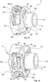
- Fig. 1
- eine Explosionsansicht einer Ausführung eines erfindungsgemäßen Steckverbinders,
- Fig. 2
- eine perspektivische Ansicht auf eine gegen eine Einsteckrichtung weisende Seite einer ersten Ausführung eines Aufnahmekörpers,
- Fig. 3
- eine perspektivische Schnittansicht auf eine Schnittfläche A - A gemäß
Figur 2 , - Fig. 4
- eine perspektivische Ansicht auf eine in die Einsteckrichtung weisende Seite der ersten Ausführung des Aufnahmekörpers,
- Fig. 5
- eine perspektivische Schnittansicht auf eine Schnittfläche B - B gemäß
Figur 4 , - Fig. 6
- eine Aufsicht in Einsteckrichtung auf eine Ausführung des erfindungsgemäßen Steckverbinders mit einem eingesteckten Steckerteil,
- Fig. 7
- eine Schnittansicht entlang C - C gemäß
Figur 6 , - Fig. 8
- eine Detailansicht des Bereichs D der Schnittansicht gemäß
Figur 7 ohne eingestecktes Steckerteil, - Fig. 9
- eine perspektivische Ansicht auf eine gegen die Einsteckrichtung weisende Seite einer zweiten Ausführung eines Aufnahmekörpers,
- Fig. 10
- eine perspektivische Schnittansicht auf eine Schnittfläche F - F gemäß
Figur 9 , - Fig. 11
- eine perspektivische Ansicht auf eine in die Einsteckrichtung weisende Seite der zweiten Ausführung des Aufnahmekörpers,
- Fig. 12
- eine perspektivische Schnittansicht auf eine Schnittfläche G - G gemäß
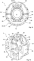
Figur 11 , - Fig. 13
- eine perspektivische Seitenansicht einer dritten Ausführung eines Aufnahmekörpers,
- Fig. 14
- eine um 90° gedrehte perspektivische Seitenansicht der dritten Ausführung des Aufnahmekörpers gemäß
Figur 13 , - Fig. 15
- eine Aufsicht auf eine in Einsteckrichtung weisende Seite der dritten Ausführung des Aufnahmekörpers gemäß
Figur 13 und - Fig. 16
- eine perspektivische Ansicht auf eine gegen die Einsteckrichtung weisende Seite der dritten Ausführung des Aufnahmekörpers gemäß
Figur 13 . - In den verschiedenen Figuren der Zeichnung sind gleiche Teile stets mit denselben Bezugszeichen versehen.
- Zu der anschließenden Beschreibung wird beansprucht, dass die Erfindung nicht auf die Ausführungsbeispiele und dabei nicht auf alle oder mehrere Merkmale von beschriebenen Merkmalskombinationen beschränkt ist, vielmehr ist jedes einzelne Teilmerkmal des/jedes Ausführungsbeispiels auch losgelöst von allen anderen im Zusammenhang damit beschriebenen Teilmerkmalen für sich und auch in Kombination mit beliebigen Merkmalen eines anderen Ausführungsbeispiels von Bedeutung für den Gegenstand der Erfindung.
- Wie in
Figur 1 dargestellt, weist der Steckverbinder 1 zur Herstellung von Schlauch und/oder Rohrverbindungen einen Grundkörper 2 und einen Aufnahmekörper 4 auf. Wie in denFiguren 7 und8 ersichtlich, weisen der Grundkörper 2 und der Aufnahmekörper 4 jeweils einen Einsteckkanal 6, 8 für ein in eine Einsteckrichtung E zu montierendes Steckerteil 10 auf. Das Steckerteil 10 ist zur Verdeutlichung in denFiguren 6 und 7 dargestellt. In denFiguren 1 bis 16 ist der Aufnahmekörper 4 in einer vorteilhaften als Klammerkäfig ausgebildeten Ausführung dargestellt. - Der Grundkörper 2 kann einseitig insbesondere mit einer nicht dargestellten Fluidleitung verbunden werden. Vorzugsweise ist dafür am Grundkörper 2, wie in den
Figuren 1 ,6 und 7 dargestellt, ein Anschlussabschnitt 12 ausgebildet. Eine anzuschließende Medienleitung kann insbesondere als Schlauch oder Rohr ausgebildet sein. Es kann vorgesehen sein, dass die Fluidleitung form- und/oder kraftschlüssig oder auch stoffschlüssig angebunden wird. Weiterhin kann der Grundkörper 2 unmittelbar an einem Aggregat oder einem anderen Element eines Fluidleitungssystems angeschlossen sein. - In dem Einsteckkanal 6 des Grundkörpers 2, kann ein Dichtungspaket angeordnet sein, welches vorzugsweise zwei Dichtungsringe 14, insbesondere elastomere O-Ringe, und dazwischen einen Abstandsring 16 umfasst. Vorzugsweise liegt dieses Dichtungspaket an einem in Einsteckrichtung E weisenden Verbindungsansatz 18 des Aufnahmekörpers 4 oder einem Stützring an. Die vorteilhafte Ausführung mit dem Stützring ist nicht dargestellt. Durch den Stützring, der wie der Abstandsring aus einem festeren Material als die O-Ringe besteht, wird einer Spaltextrusion der elastomeren O-Ringe entgegengewirkt. Das Dichtungspaket dichtet dabei zweckmäßig einen Außenumfang eines Dichtabschnitts des zu montierenden Steckerteils 10 nach dessen Montage gegen eine Innenwandung des Einsteckkanals 6 des Grundkörpers 2 ab.
- Bei dem Steckerteil 10 handelt es sich insbesondere um einen SAE J 2044 Male-Stecker. Wie exemplarisch in der
Figur 7 dargestellt, ist das Steckerteil 10 hohlzylindrisch ausgebildet und weist insbesondere den Dichtungsabschnitt 20 und einen in Einsteckrichtung E vor dem Dichtungsabschnitt 20 angeordneten Verriegelungsabschnitt 22 auf. Der Dichtungsabschnitt 20 ist in einem eingesteckten Zustand vorzugsweise vollständig im Einsteckkanal 6, 8 des Grundkörpers 2 und des Aufnahmekörpers 4 angeordnet. Insbesondere wird der Dichtungsabschnitt 20 von dem Verriegelungsabschnitt 22 durch einen im Durchmesser vergrößerten umlaufenden Ringbund 24 separiert. - Der Steckverbinder 1 weist ein in
Figur 1 dargestelltes, insbesondere in der dargestellten Ausführungsform als Halteklammer ausgebildetes Halteteil 28 auf, welches, wie in denFiguren 6 bis 8 dargestellt, in einer Aufnahmeöffnung 26 des Aufnahmekörpers 4 angeordnet ist. Entsprechend der Darstellung gemäß denFiguren 6 und 7 blockiert das Halteteil 28 in einer Riegelstellung das zu montierende Steckerteil 10 entgegen der Einsteckrichtung E. - Der Aufnahmekörper 4 ist insbesondere als ein Klammerkäfig ausgebildet. Das als Halteklammer ausgebildete Halteteil 28 ist vorzugsweise senkrecht zur Einsteckrichtung E in den Klammerkäfig einsteckbar. Das als Halteklammer ausgebildete Halteteil 28 weist dabei insbesondere ein in Einsteckrichtung E betrachtet U-förmiges Profil auf. Die Aufnahmeöffnung 26 im Aufnahmekörper 4 ist insbesondere komplementär zu der Halteklammer senkrecht zur Einsteckrichtung E im Aufnahmekörper 4 ausgebildet und insbesondere auf zwei gegenüberliegenden Seiten geöffnet, insbesondere weist die Aufnahmeöffnung 26 eine Eintrittsöffnung und eine Austrittsöffnung auf.
- Das Halteteil 28 ist zweckmäßig in der Aufnahmeöffnung 26 des Aufnahmekörpers 4 vormontierbar. Das als Halteklammer ausgebildete Halteteil 28 kann dabei vorzugsweise zumindest zwei Stellungen, eine Lösestellung und eine Riegelstellung, insbesondere drei Stellungen, nämlich zusätzlich eine Vormontagestellung, einnehmen. In den nicht dargestellten Löse- und Vormontagestellungen ist das zu montierende Steckerteil 10 durch die Halteklammer in den Einsteckkanal 6, 8 einführbar. Insbesondere zumindest in der Lösestellung ist das Steckerteil 10 gegen die Einsteckrichtung E aus dem Einsteckkanal 6, 8 entnehmbar. Vorzugsweise in der Riegelstellung verriegelt die Halteklammer, entsprechend
Figur 7 , das Steckerteil 10 formschlüssig, indem die Halteklammer den Ringbund 24 des Steckerteils 10 gegen eine Bewegung gegen die Einsteckrichtung E blockiert. - Das als Halteklammer ausgebildete Halteteil 28 weist insbesondere, wie in
Figur 1 dargestellt, zwei Paare von Federarmen auf. Zweckmäßig besteht ein Paar der Federarme aus jeweils einem Positionsarm 30 und einem Funktionsarm 32. Insbesondere sind die Positionsarme 30 jeweils in Einsteckrichtung E gesehen hinter dem jeweiligen Funktionsarm 32 angeordnet. - Die Funktionsarme 32 und Positionsarme 30 sind dabei jeweils radial zum Einsteckkanal 6, 8 gegenüberliegend zueinander angeordnet. Vorteilhaft sind die Positionsarme 30 als Verliersicherung ausgebildet und hintergreifen in einer Vormontagestellung der Halteklammer ein Lageelement, welches in der Aufnahmeöffnung 26 ausgebildet ist.
- Die Funktionsarme 32 weisen insbesondere eine vorzugsweise zum Einsteckkanal 6, 8 senkrecht ausgebildete, in Einsteckrichtung E weisende Blockierseite 34 und eine gegen die Einsteckrichtung E weisende und zumindest bereichsweise abgeschrägte Einführseite 36 auf. Die Einführseite 36 ist derart abgeschrägt, dass beim Einstecken des zu montierenden Steckerteils 10 die Einführseite 36 mit dem abgeschrägten Abschnitt in Anlagekontakt mit dem Ringbund 24 des Steckerteils 10 kommt und die Funktionsarme 32 radial zum Einsteckkanal 6, 8 nach außen elastisch verformt werden. Die Blockierseite 34 ist derart ausgebildet, dass sobald der Steckerteil 10 so weit in Einsteckrichtung E in den Einsteckkanal 6, 8 eingesteckt ist, dass der Ringbund 24 des Steckerteils 10 in Einsteckrichtung E hinter dem Funktionsarm 32 angeordnet ist, sich der Funktionsarm 32 radial zum Einsteckkanal 6, 8 rückverformt und mit der Blockierseite 34 den Ringbund 24 gegen die Einsteckrichtung E formschlüssig blockiert.
- Das Steckerteil 10 wird vorteilhafterweise so weit in Einsteckrichtung E in den Einsteckkanal 6, 8 des Grundkörpers 2 und des Aufnahmekörpers 4 eingesteckt, bis der Ringbund 24 von dem Funktionsarm 32 hintergriffen wird. Bei diesem Montageverfahren ist vorzugsweise ein so genanntes Überstecken, d. h. ein im Hinblick auf die eigentliche Rastposition übermäßiges Einstecken des Steckerteils 10 in Einsteckrichtung E, um das Hintergreifen des Halteteils 28 zu ermöglichen, vorteilhaft. Diesbezüglich bildet der in Einsteckrichtung E hinterste Abschnitt des Einsteckkanals 6 des Grundkörpers 2 einen in
Figur 7 dargestellten Übersteckraum 38. - Auf einer gegen die Einsteckrichtung E weisenden Stirnwand 44 des Aufnahmekörpers 4 können sich, wie in den
Figuren 1 bis 3 ,6 ,9 ,10 und16 dargestellt, vorteilhaft Führungsschlitze zum Eingriff von komplementären, in denFiguren 1 und6 dargestellten, Führungszapfen 46 befinden. Die Führungszapfen 46 sind an den Funktionsarmen ausgebildet und stehen von diesen gegen die Einsteckrichtung E ab. - Die Führungsschlitze sind zweckmäßig jeweils als Langlöcher 48 mit Knickwinkeln ausgebildet, wodurch die Langlöcher 48 eine Steuerkontur für die Führungszapfen 46 bilden. Durch das Zusammenwirken der Steuerkontur mit den Führungszapfen 46 wird vorteilhaft konstruktiv eine Einführbewegung und eine Ausschubbewegung des als Halteklammer ausgebildeten Halteteils 28 senkrecht zur Einsteckrichtung E begrenzt und eine Bewegung der Funktionsarme 32 radial zum Einsteckkanal 6, 8 gesteuert. Vorteilhaft kann durch die Steuerkontur zumindest eine Vormontagestellung, eine Lösestellung und eine Riegelstellung der Halteklammer in der Aufnahmeöffnung 26 eingestellt werden. In der Riegelstellung sind die Führungszapfen 46 in einer Riegelkontur 50 der Steuerkontur angeordnet, welche sich zwischen einer Vormontagekontur 52 und einer Lösekontur 54 befindet. Die Riegelkontur 50, die Steuerkontur und die Lösekontur 54 sind über das Langloch 48 miteinander verbunden.
- Durch einen radialen Druck von außerhalb des Steckverbinders 1 auf einen Löseangriff 56 der Halteklammer oder von einem Druck innerhalb des Steckverbinders 1 auf die Einführseite 36 der Funktionsarme 32 beim Einstecken des zu montierenden Steckerteils 10 in den Einsteckkanal 8 des Aufnahmekörpers 4 ist die Halteklammer aus der Riegelstellung in die Lösestellung überführbar, indem die Führungszapfen 46 der Funktionsarme 32 der Steuerkontur der Langlöcher 48 folgen.
- In dem Vormontagezustand sind die Führungszapfen 46 insbesondere in der Vormontagekontur 52 angeordnet. Aus der Vormontagestellung ist die Halteklammer vorteilhaft durch einen radialen Druck von außerhalb des Steckverbinders 1 auf den Löseangriff 56 der Halteklammer oder von einem Druck innerhalb des Steckverbinders 1 auf die Einführseite 36 der Funktionsarme 32 beim Einstecken des zu montierenden Steckerteils 10 in den Einsteckkanal 8 des Aufnahmekörpers 4 in die Riegelstellung überführbar, indem die Führungszapfen 46 der Funktionsarme 32 der Steuerkontur der Langlöcher 48 folgen.
- Wie in den
Figuren 7 und8 dargestellt, ist der Aufnahmekörper 4 mit dem Grundkörper 2 verbunden. Weiterhin ist in denFiguren 7 und8 dargestellt, dass das Halteteil 28 eine gegen die Einsteckrichtung E weisende Anschlagfläche 40 aufweist. Der Anschlagfläche 40 zugewandt, weist die Aufnahmeöffnung 26 eine in Einsteckrichtung E weisende Anlagefläche 42 auf. Die Anschlagfläche 40 wirkt dabei, wie inFigur 8 abgebildet, bei einer Verschiebung des Halteteils 28 entgegen der Einsteckrichtung E gegen die Anlagefläche 42 des Aufnahmekörpers 4. Der Aufnahmekörper 4 ist dabei derart elastisch verformbar ausgebildet, dass die Anlagefläche 42 zumindest innerhalb eines Verschiebebereichs entgegen der Einsteckrichtung E elastisch verschiebbar ist. - Gemäß einer nicht dargestellten Ausführung kann der Steckverbinder 1 und/oder die mit dem zu montierenden Steckerteil 10 verbundene Fluidleitung elektrisch beheizt ausgebildet sein. Vorteilhaft ist zur Beheizung des Steckverbinders 1 ein Heizmittel an dem Grundkörper 2 und/oder dem Aufnahmekörper 4 angeordnet, insbesondere um den Grundkörper 2 und/oder den Aufnahmekörper 4 gewickelt. Das Heizmittel ist vorzugsweise als elektrisches Heizmittel, insbesondere als ein ein- oder mehradriger Heizdraht bzw. Heizleiter ausgebildet.
- Zweckmäßig weist der Grundkörper 2, wie in den
Figuren 1 ,7 und8 dargestellt, einen Heizabschnitt auf, in dem das Heizmittel angeordnet wird. Insbesondere weist der Grundkörper 2 im Heizabschnitt zumindest ein Führungselement 58 zur Führung und Lenkung des Heizmittels auf. Das Führungselement 58 ist gemäß einer bevorzugten Ausführungsform eine wendelförmige Führungsrille, welche sich um den Umfang des Grundkörpers 2 spiralartig erstreckt. - Erfindungsgemäß weist der Aufnahmekörper 4, wie in den
Figuren 1 bis 6 und8 bis 14 dargestellt, ein Widerstandselement 69 auf. Das Widerstandselement 69 erzeugt bei einer Verschiebung der Anlagefläche 42 über den Verschiebebereich hinaus einen Widerstand gegen eine weitere elastische Verformung des Aufnahmekörpers 4 gegen die Einsteckrichtung E. - Zweckmäßig weist der Aufnahmekörper 4 aufgrund der erfindungsgemäßen Ausführung zumindest zwei Verschiebebereiche auf. Die Verschiebebereiche weisen dabei unterschiedlich starke Widerstände gegen eine Verschiebung der Anlagefläche 42 auf. Vorteilhaft ist dabei, dass durch die elastische Verformung des Aufnahmekörpers 4 ein elastischer Bereich zur Verfügung gestellt wird, welcher im Betrieb Druckpulsation und Druckschwankungen ausgleichen kann. Das Widerstandselement 69 stellt dahingehend einen Widerstandsbereich zum Schutz vor einer Überlastung, z. B. durch eine Verformung über den Verschiebebereich hinaus, zur Verfügung.
- Der Verschiebebereich ist im erfindungsgemäßen Sinne keine Limitierung des elastischen Bereichs. Insbesondere kann der Aufnahmekörper 4 auch über den Verschiebebereich hinaus noch elastisch verformbar sein. Der Aufnahmekörper 4 ist jedoch durch eine Verschiebung der Anlagefläche 42 entgegen der Einsteckrichtung E innerhalb des Verschiebebereichs nicht plastisch verformbar.
- Der Aufnahmekörper 4 bzw. die Anlagefläche 42 des Aufnahmekörpers 4 wird insbesondere bei außergewöhnlich hohen Drücken im Betrieb oder einem gefrierenden Fluid, insbesondere einem in einem Übersteckraum 38, dargestellt in
Figur 7 , gefrierenden Fluid, über den Verschiebebereich hinaus verformt. - Wenn ein Fluid im Steckverbinder 1 gefriert, dehnt sich dieses Fluid aus und vergrößert sein Volumen. Dadurch wird eine auf ein vorderes Ende des Steckerteils 10 gegen die Einsteckrichtung E wirkende Lösekraft auf das Steckerteil 10 ausgeübt, siehe erste Lösekraft F1 in
Figur 7 . Das Steckerteil 10 wiederum überträgt die Lösekraft durch seine formschlüssige Verbindung gegen die Einsteckrichtung E mit dem Ringbund 24 auf das Halteteil 28, insbesondere auf die Blockierseite 34 der Funktionsarme 32, siehe zweite Lösekraft F2 inFigur 7 . Erfindungsgemäß ist das Halteteil 28 in der Aufnahmeöffnung 26 angeordnet und überträgt daraufhin die Lösekraft über die Anschlagfläche 40 auf die Anlagefläche 42 der Aufnahmeöffnung 26, wodurch der Aufnahmekörper 4 verformt bzw. die Anlagefläche 42 verschoben wird, siehe dritte Lösekraft F3 inFigur 7 . - Wenn der Druck im Fluidsystem ansteigt, kann mittels des Verschiebewegs schnell das Volumen für das Fluid vergrößert werden, so dass der auf den Steckverbinder 1 wirkende Druck abnimmt. Um allerdings die Verschiebung zu begrenzen und insbesondere eine plastische Verformung zu vermeiden, begrenzt das Widerstandselement 69 eine weitere Verschiebung der Anlagefläche 42, wobei durch die ermöglichte Volumenvergrößerung der restliche im Fluidsystem herrschende Druck derart reduziert ist, dass dieser nicht mehr zu einer Zerstörung des Steckverbinders 1 oder einer plastischen Verformung desselbigen führt.
- Insbesondere entsprechend den in den
Figuren 1 bis 5 ,9 bis 14 und16 dargestellten vorteilhaften Ausführungsformen weist der Aufnahmekörper 4 zwei parallel zur Einsteckrichtung E versetzte und sich jeweils in einer Ebene senkrecht zur Einsteckrichtung E erstreckende Tellerelemente 60, 62 auf. Die Tellerelemente 60, 62 sind insbesondere elastisch verformbar und begrenzen die Aufnahmeöffnung 26. Zweckmäßig weist das in Einsteckrichtung E betrachtet vordere erste Tellerelement 60 die Anlagefläche 42 für die Anschlagfläche 40 des Halteteils 28 auf. Weiterhin weist das in Einsteckrichtung E betrachtet vordere erste Tellerelement 60 insbesondere die Steuerkontur bzw. die Langlöcher 48 zur Führung der Führungszapfen 46 der Halteklammer auf. - Gemäß einer weiteren vorteilhaften Ausführung weist der Aufnahmekörper 4 zumindest einen Dehnungssteg 64, insbesondere zwei um den Einsteckkanal 6, 8 versetzte Dehnungsstege 64, auf. Die Dehnungsstege 64 sind dabei zweckmäßig entgegen der Einsteckrichtung E und insbesondere in die Einsteckrichtung E elastisch verformbar ausgebildet.
- Insbesondere die in den
Figuren 1 bis 16 dargestellten vorteilhaften Ausführungsformen weisen die Dehnungsstege 64 auf. Die Dehnungsstege 64 optimieren dabei die Elastizität des Aufnahmekörpers 4 in der Art, dass die Elastizität an die Druckbedingungen und den Einsatzzweck angepasst werden kann bzw. angepasst ist. Besonders vorteilhaft beschränken die Dehnungsstege 64, wie dargestellt, die Aufnahmeöffnung 26 radial zum Einsteckkanal 6, 8 betrachtet. - In den
Figuren 1 bis 5 ,7 bis 14 und16 sind zudem vorteilhafte Ausführungen dargestellt, gemäß welchen die Dehnungsstege 64 die Tellerelemente 60, 62 miteinander verbinden. Insbesondere sind die Dehnungsstege 64 dabei an einem äußeren Umfang der Tellerelemente 60, 62 angeordnet. Vorteilhaft sind die Tellerelemente 60, 62 dabei selbst elastisch verformbar, ebenso wie die Dehnungsstege 64, so dass über die konstruktive Gestaltung der Dehnungsstege 64 und der Tellerelemente 60, 62 die elastische Verformbarkeit bzw. der Verschiebebereich des Aufnahmekörpers 4 eingestellt werden kann. - Vorteilhaft weist der Aufnahmekörper 4 zumindest eine Materialeinsparung 66 auf. Die Materialeinsparung 66 ist insbesondere als eine Einkerbung oder ein Durchbruch oder eine Einschnürung oder dergleichen ausgebildet. Die Materialeinsparung 66 erhöht die Elastizität bzw. die Verformbarkeit des Aufnahmekörpers 4 und reduziert den Widerstand entgegen der Einsteckrichtung E. Durch die Materialeinsparungen 66 wird insbesondere eine homogene Struktur des Aufnahmekörpers 4 unterbrochen. Vorzugsweise weisen das erste und/oder das zweite Tellerelement 60, 62 und/oder jeweils die Dehnungsstege 64, wie in den
Figuren 9 bis 14 und16 dargestellt, zumindest eine derartige Materialeinsparung 66 auf. Insbesondere kann eine Materialeinsparung 66 senkrecht und/oder parallel, wie in denFiguren 13 bis 16 dargestellt, zu der Einsteckrichtung E im Aufnahmekörper 4 ausgebildet sein. Besonders vorteilhaft ist bei der in denFiguren 13 bis 16 dargestellten Ausführung des Aufnahmekörpers 4 die Verbindung der Tellerelemente optimiert, um die Kraft-Weg-Kurve an mögliche Anforderungen anzupassen. Weiterhin ist vorteilhaft der Aufnahmekörper 4 durch die, zur Einsteckrichtung E parallel ausgebildeten, Materialeinsparungen 66 besonders stabil und auch einfach in der Herstellung. - Zweckmäßig können die Materialeinsparungen auch tangential zu einer Kreisbahn um den Einsteckkanal 8 des Aufnahmekörpers ausgebildet sein, wie insbesondere in den
Figuren 11 und12 in dem zweiten Tellerelement 62 dargestellt. - Insbesondere in den
Figuren 3 ,5 ,6 ,9 bis 12 und16 ist eine als Einkerbung ausgebildete Materialeinsparung 66, welche an der Stirnwand 44 des ersten Tellerelements 60 oder an der in Einsteckrichtung weisenden Rückseite 68 des zweiten Tellerelements 62 ausgebildet ist, dargestellt. Weiterhin sind in denFiguren 4, 5 ,11 bis 15 Materialeinsparungen 66 vorteilhaft als Durchbrüche, insbesondere Schlitze, ausgebildet, welche in dem zweiten Tellerelement 62 ausgebildet sind. - Besonders vorteilhaft ist, wie in den
Figuren 9 bis 16 dargestellt, die Materialeinsparung 66 in Form von Durchbrüchen, insbesondere Freischnitte, in den Dehnungsstegen 64 ausgebildet. - Erfindungsgemäß ist das Widerstandselement 69, wie in den
Figuren 1 bis 6 ,8 ,7 und9 bis 14 dargestellt, als ein sich im Aufnahmekörper 4 parallel zur Einsteckrichtung E erstreckender Ambossarm 70 ausgebildet. Erfindungsgemäß ist der Ambossarm 70 einseitig mit dem Aufnahmekörper 4 stoffschlüssig verbunden oder angeformt und mit seinem freien Ende in einer Ambossaufnahme 72 im Aufnahmekörper 4 angeordnet. - Insbesondere ist, wie in
Figur 8 dargestellt, der Kontaktabschnitt 74 an einem Überstand 75 an einem freien Ende des Ambossarms 70 ausgebildet. Insbesondere ist zwischen dem Kontaktabschnitt 74 des Überstands 75 und einer korrespondierend ausgebildeten Kontaktfläche 76 der Ambossaufnahme 72 ein Spalt ausgebildet. Bei einer Verformung des Aufnahmekörpers 4, insbesondere beim Verschieben der Anlagefläche 42 entgegen der Einsteckrichtung E, wird der Ambossarm 70 durch seine stoffschlüssige Verbindung mitgeschleppt, wodurch sich der Spalt verringert. - Vorteilhaft steigert das Widerstandselement 69 bei einem Anlagekontakt des Kontaktabschnitts 74, insbesondere dem Überstand 75, mit der Kontaktfläche 76 den Widerstand gegen eine weitere Verformung des Aufnahmekörpers 4 gegen die Einsteckrichtung E.
- Besonders vorteilhaft kann der Spalt zwischen dem Kontaktabschnitt 74, insbesondere des Überstands 75, des Ambossarms 70 und der Kontaktfläche 76 der Ambossaufnahme 72 an die elastische Verformbarkeit des Aufnahmekörpers 4 derart angepasst werden, dass der Anlagekontakt zwischen dem Kontaktabschnitt 74 des Ambossarms 70 und der Kontaktfläche 76 eintritt, insbesondere bevor die Verschiebung der Anlagefläche 42 zu einer plastischen Verformung oder einer Zerstörung des Aufnahmekörpers 4 führt.
- Entsprechend der Ausführung in den
Figuren 9 bis 14 ist vorteilhaft zumindest ein Ambossarm 70 beidseitig mit den Tellerelementen 60, 62 verbunden. - Zweckmäßig ist zumindest ein beidseitig mit den Tellerelementen 60, 62 verbundener Ambossarm 70 einseitig mit einem den Kontaktabschnitt 74 bildenden Überstand 75 ausgebildet. Dabei ist das den Überstand 75 aufweisende Ende radial zum Einsteckkanal 6, 8 vorteilhaft mit einem Verbindungssteg 77 mit dem Tellerelement 60, 62 verbunden. Diese Ausführung des Ambossarms 70 ist in
Figur 9 zu erkennen. - Besonders vorteilhaft sind, wie in den
Figuren 9 und16 dargestellt, in Umfangsrichtung zu dem Einsteckkanal 6, 8 betrachtet Materialeinsparungen 66 benachbart zu dem Verbindungssteg 77 in dem Tellerelement 60 ausgebildet. - Die
Figuren 12 und14 zeigen eine weitere Ausführung des Aufnahmekörpers, wobei zumindest ein beidseitig mit den Tellerelementen 60, 62 verbundener Ambossarm 70 derart mit dem Tellerelement 60, 62 verbunden ausgebildet ist, dass der Kontaktabschnitt 74 als ein Teil des Tellerelements 60, 62 selbst ausgebildet ist. Vorteilhaft geht der Ambossarm 70 gemäß dieser Ausführung beidseitig derart in die Tellerelemente 60, 62 über, dass sich der Ambossarm 70 aus einer zur Aufnahmeöffnung 26 weisenden bzw. die Aufnahmeöffnung 26 begrenzenden Oberfläche des jeweiligen Tellerelements 60, 62 heraus erstreckt. Um bei dieser Ausführung die Elastizität und die für eine Verschiebung erforderliche Kraft der Tellerelemente 60, 62 zu begünstigen, ist der Bereich des Tellerelements 60, 62, in den der Ambossarm 70 mit seinen Kontaktabschnitten 74 übergeht, als eine Dehnungsbrücke 79, wie in denFiguren 11 ,12 ,14 und15 dargestellt, ausgebildet. - Vorteilhaft ist radial zur Dehnungsbrücke 79 in Richtung des Einsteckkanals 6, 8 versetzt und über den Bogenabschnitt der Dehnungsbrücke 79 eine Materialeinsparung 66 in Form eines axialen Durchbruchs in dem Tellerelement 60, 62, in den
Figuren 12 ,14 und15 in dem zweiten Tellerelement 62, ausgebildet. Zweckmäßig wird bei einer axialen Verschiebung der Anlagefläche 42 die Dehnungsbrücke zusammen mit dem mit ihr verbundenen Ambossarm 70 gegen die Einsteckrichtung E verschoben. - In den
Figuren 2 bis 5 und8 ist eine weitere Ausführung der Ambossarme 70 bzw. des zumindest einen Ambossarms 70 dargestellt. Vorteilhaft ist dabei zumindest ein Ambossarm 70 einseitig mit dem Aufnahmekörper 4, insbesondere mit einem Tellerelement 60, 62, stoffschlüssig verbunden oder angeformt. Zweckmäßig ist das der stoffschlüssigen Verbindung gegenüberliegende Ende des Ambossarms 70 als ein freies Ende ausgebildet. Das freie Ende ist insbesondere, wie inFigur 5 dargestellt, in der Ambossaufnahme 72 im Aufnahmekörper 4 angeordnet. Zur Erhöhung des Widerstands gegen eine axiale Verschiebung der Anlagefläche 42 ist der Kontaktabschnitt 74 vorzugsweise als ein Überstand 75 am freien Ende des Ambossarms 70 ausgebildet. Der Überstand 75 bzw. der Kontaktabschnitt 74 ist dabei insbesondere entsprechend dem Überstand 75 bzw. dem Kontaktabschnitt 74 der Ausführung inFigur 10 ausgebildet. - Insbesondere hat zumindest eines der Tellerelemente 60, 62 zumindest einen sich parallel zur Einsteckrichtung E und zum jeweiligen anderen Tellerelements 60, 62 erstreckenden Ambossarm 70 stoffschlüssig verbunden oder angeformt. Diese Ausführung ist insbesondere in den
Figuren 1 bis 6 ,8 und10 bis 14 dargestellt. Dabei ist die korrespondierende Ambossaufnahme 72 vorteilhafterweise im jeweiligen anderen Tellerelement 60, 62 angeordnet. Zweckmäßig sind die Tellerelemente 60, 62 über den Ambossarm 70 bei einem Anlagekontakt des Kontaktabschnitts 74 des Ambossarms 70 und der Kontaktfläche 76 der Ambossaufnahme 72 zur Steigerung des Widerstands gegen eine Verformung bzw. Verschiebung entgegen der Einsteckrichtung E miteinander verbunden. - Zur Justierung des Widerstands, welcher aus dem Ambossarm 70 resultiert, kann der Ambossarm 70 selbst und/oder die Ambossaufnahme 72 elastisch gegen die Einsteckrichtung E verformbar ausgebildet sein.
- Vorteilhaft bildet die Ambossaufnahme 72 in dem jeweiligen Tellerelement 60, 62 eine Materialeinsparung 66, welche wiederum die Elastizität gegen die Einsteckrichtung E erhöht und den Widerstand verringert. Gemäß einer bevorzugten Ausführung ist daher radial des Einsteckkanals 6, 8 und gegenüberliegend der Ambossaufnahme 72 im Tellerelement 60, 62 jeweils eine als Einkerbung ausgebildete Materialeinsparung 66 im jeweiligen Tellerelement 60, 62 ausgebildet. Insbesondere die
Figuren 1 bis 7 ,9 bis 12 und16 zeigen eine entsprechende vorteilhafte Ausführungsform. - In vorteilhafter Ausführung weist der Aufnahmekörper 4 zwei oder mehr Ambossarme 70 und entsprechende Ambossaufnahmen 72 auf. In einer vorteilhaften Ausführung weist der Aufnahmekörper 4 zwei Ambossarme 70 und zwei Ambossaufnahmen 72 auf. Die Ambossaufnahmen 72 und Ambossarme 70 sind vorzugsweise gleichmäßig um den Einsteckkanal 6, 8 verteilt angeordnet. Insbesondere sind zwei Ambossarme 70 und Ambossaufnahmen 72 diametral zum Einsteckkanal 6, 8 angeordnet.
- Gemäß einer weiteren alternativen Ausführung sind die zumindest zwei Ambossarme 70 und zwei Ambossaufnahmen 72 derart ausgebildet, dass sie beim Erreichen der bestimmten Verformung des Aufnahmekörpers 4 gleichzeitig mit ihren jeweiligen Kontaktabschnitten 74 in Anlagekontakt mit ihren jeweiligen zugeordneten Kontaktflächen 76 der Ambossaufnahmen 72 kommen. Besonders vorteilhaft wird dadurch beginnend mit dem Erreichen bzw. Überschreiten des Verschiebewegs unmittelbar ein Widerstand erzeugt. Eine derartige Ausführung zeichnet sich insbesondere über zwei Widerstandsbereiche aus, vorteilhaft einen ersten Widerstandsbereich, in dem sich der Aufnahmekörper 4 bzw. dessen Verformung im Verschiebebereich befindet und einen zweiten Widerstandsbereich, ab dem Ausmaß der Verschiebung der Anlagefläche 42, an dem die Ambossarme 70 mit ihren jeweiligen Kontaktabschnitten 74 in Anlagekontakt mit ihren jeweiligen zugeordneten Kontaktflächen 76 der Ambossaufnahmen 72 kommen.
- Eine weitere vorteilhafte Ausführungsform der Erfindung betrifft ebenfalls einen Aufnahmekörper 4, welcher zumindest zwei Ambossarme 70 und zwei Ambossaufnahmen 72 aufweist. Vorteilhaft sind die Ambossarme 70 und Ambossaufnahmen 72 derart ausgebildet, dass sie beim Erreichen zumindest zwei verschiedener bestimmter elastischer Verformungen des Aufnahmekörpers 4 mit ihren jeweiligen Kontaktabschnitten 74 nacheinander in Anlagekontakt mit ihren jeweiligen zugeordneten Kontaktflächen 76 der Ambossaufnahmen 72 kommen. Vorteilhaft wird erreicht, das beim Erreichen jeder bestimmten elastischen Verformung des Aufnahmekörpers 4 jeweils ein weiterer Widerstand gegen die Verschiebung der Anlagefläche 42 des Aufnahmekörpers 4 erzeugt wird, so dass der Widerstand gegen die Einsteckrichtung E stufenweise steigt. Die verschiedenen bestimmten elastischen Verformungen des Aufnahmekörpers 4 unterscheiden sich insbesondere über ein Ausmaß der elastischen Verschiebung der Anlagefläche 42 des Aufnahmekörpers 4 gegen die Einsteckrichtung E. Vorteilhaft weist ein Steckverbinder 1 dieser Art den ersten Widerstandsbereich, in dem sich der Aufnahmekörper 4 bzw. dessen Verformung im Verschiebebereich befindet, auf und weiterhin mindestens einen zweiten und dritten Widerstandsbereich, an denen die Ambossarme 70 mit ihren jeweiligen Kontaktabschnitten 74 in Anlagekontakt mit ihren jeweiligen zugeordneten Kontaktflächen 76 der Ambossaufnahmen 72 kommen.
- Zweckmäßig ist zumindest ein Ambossarm 70 mit seinem freien Ende in Einsteckrichtung E weisend ausgebildet und zumindest ein Ambossarm 70 mit seinem freien Ende gegen die Einsteckrichtung E weisend ausgebildet. Diese Ausführung ist in den
Figuren 1 ,2 und 3 dargestellt und ermöglicht eine Anpassung der Bauteilherstellung an bestehende Werkzeugbedingungen. Gemäß der in den genannten Figuren dargestellten Ausführung ist der Ambossarm 70 an dem ersten in Einsteckrichtung E gesehen vorderen Tellerelement 60 angeordnet und erstreckt sich in die Ambossaufnahme 72 des zweiten in Einsteckrichtung E gesehen hinteren Tellerelements 62. Diametral zum Einsteckkanal 6, 8 gegenüberliegend ist der Ambossarm 70 an dem zweiten Tellerelement 62 angeordnet und erstreckt sich in die Ambossaufnahme 72 des ersten Tellerelements 60. - Gemäß einer weiteren vorteilhaften Ausführung, welche insbesondere in den
Figuren 9 bis 12 dargestellt ist, ist zumindest ein beidseitig mit den Tellerelementen 60, 62 verbundener Ambossarm 70 zumindest einseitig mit dem Überstand 75 ausgebildet. Zweckmäßig ist dabei das den Überstand 75 aufweisende Ende des Ambossarms 70 radial zum Einsteckkanal 6, 8 mit dem Verbindungssteg 77 mit dem Tellerelement 60, 62 verbunden. Weiterhin ist in dieser vorteilhaften Ausführung zumindest ein weiterer beidseitig mit den Tellerelementen 60, 62 verbundener Ambossarm 70 derart mit den Tellerelementen 60, 62 verbunden ausgebildet, dass der Kontaktabschnitt 74 selbst als ein Teil des Tellerelements 60, 62 ausgebildet ist. - Vorteilhaft weist der Einsteckkanal 8 des Aufnahmekörpers 4 in einer nicht dargestellten weiteren Variante ein axiales Steckspiel zur Lagerung des zu montierenden Steckerteils 10 auf. Das Steckspiel dient insbesondere dem Überstecken des Steckerteils 10 bei dessen Montage. Das Steckspiel wird vorzugsweise begrenzt durch ein in Einsteckrichtung E betrachtet hinteren Anschlag 78 für den Ringbund 24 des Steckerteils 10 im Einsteckkanal 8 des Aufnahmekörpers 4 und das in Einsteckrichtung E betrachtet vor dem hinteren Anschlag 78 angeordnete Halteteil 28 in Riegelstellung. Zweckmäßig ist dabei ein Rückstellelement zumindest teilweise in dem Aufnahmekörper 4 angeordnet und kann eine in Einsteckrichtung E auf den Ringbund 24 des zu montierenden Steckerteils 10 wirkende Rückstellkraft erzeugen. Vorteilhaft wird dadurch der Übersteckraum 38 möglichst gering gehalten, so dass sich weniger Fluid, welches gefrieren und sich ausdehnen kann, im Übersteckraum 38 ansammeln kann.
- Für eine besonders vorteilhafte Herstellung sind der Aufnahmekörper 4 und/oder das Halteteil 28 und/oder der Grundkörper 2 monolithisch ausgebildet und im Spritzgussverfahren hergestellt.
- Zum Zweck einer besonders hohen Belastbarkeit sind der Aufnahmekörper 4 und der Grundkörper 2 gemäß einer vorteilhaften Ausführung stoffschlüssig, insbesondere lasergeschweißt, miteinander verbunden. Alternativ kann zwecks vereinfachter Instandsetzungen und/oder Anpassungen der Aufnahmekörper 4 und/oder der Grundkörper 2 Rast- und/oder Schraubelemente aufweisen, mit welchen der Grundkörper 2 und der Aufnahmekörper 4 miteinander verbunden sind. Insbesondere wenn der Grundkörper 2 unlösbar, z. B. mit einem Aggregat verbunden ist, ist eine vom Grundkörper 2 trennbare Ausführung des Grundkörpers 2 und Aufnahmekörpers 4 von Vorteil.
- Nachfolgend ist ein Montagebeispiel bei einer vorteilhaften Ausführung eines Steckverbinders 1 mit einem Grundkörper 2 und einem Aufnahmekörper 4 beschrieben.
- Zur Vormontage des Steckverbinders 1 wird zunächst das Dichtpaket in den Grundkörper 2 eingesetzt.
- Anschließend wird der Aufnahmekörper 4 mit dem Grundkörper 2 zusammengeführt und insbesondere stoffschlüssig verbunden.
- Danach wird das Halteteil 28, insbesondere die Halteklammer, senkrecht zur Einsteckrichtung E in die Aufnahmeöffnung 26 des Aufnahmekörpers 4 eingesetzt, so dass zunächst der Vormontagezustand entsteht, bei dem die Führungszapfen 46 der Funktionsarme 32 in die komplementären Führungsschlitze eingreifen. In der Vormontagestellung sind die Führungszapfen 46 in der Vormontagekontur 52 angeordnet und das Lageelement in der Aufnahmeöffnung 26 von den Positionsarmen hintergriffen. In diesem Zustand kann der Steckverbinder 1 ausgeliefert werden.
- Alternativ, gegebenenfalls sogar bevorzugt, kann der Aufnahmekörper 4 auch schon vor dem Verbinden mit dem Grundkörper 2 mit dem Halteteil, insbesondere der Halteklammer, vormontiert werden.
- Bei der späteren Endmontage wird das Steckerteil 10 in Einsteckrichtung E in den Einsteckkanal 6, 8 eingeführt. Dabei berührt der Ringbund 24 des Steckerteils 10 beim Passieren des Halteteils 28 insbesondere die Einführseite 36 der Funktionsarme 32. Vorzugsweise ist die Funktionsseite derart ausgebildet, dass die Halteklammer vor einem radialen Aufweiten der Funktionsarme 32 radial tiefer in die Aufnahmeöffnung 26 eingezogen und demzufolge radial elastisch aufgeweitet wird. Danach können die Funktionsarme 32 schließlich hinter dem Ringbund 24 einrasten und eine Bewegung des Steckerteils 10 gegen die Einsteckrichtung E mit ihrer Blockierseite 34 blockieren.
- Zum Lösen der Steckverbindung wird die Halteklammer durch Drücken auf ihren Löseangriff 56 tiefer in die Aufnahmeöffnung 26 verschoben. Dadurch werden die Führungszapfen 46 in der Führungskontur der Führungsschlitze radial nach außen in die Lösekontur 54 verschoben. Folglich werden dadurch die Funktionsarme 32 aufgeweitet, so dass durch das Aufweiten der Funktionsarme 32 der Ringbund 24 wieder freigegeben wird. Die Verbindung kann nun gelöst werden, indem das Steckerteil 10 entgegen der Einsteckrichtung E aus dem Steckverbinder 1 gezogen wird.
-
- 1
- Steckverbinder
- 2
- Grundkörper
- 4
- Aufnahmekörper
- 6
- Einsteckkanal des Grundkörpers
- 8
- Einsteckkanal des Aufnahmekörpers
- 10
- Steckerteil
- 12
- Anschlussabschnitt
- 14
- Dichtungsring
- 16
- Abstandsring
- 18
- Verbindungsansatz
- 20
- Dichtungsabschnitt
- 22
- Verriegelungsabschnitt
- 24
- Ringbund
- 26
- Aufnahmeöffnung
- 28
- Halteteil
- 30
- Positionsarm
- 32
- Funktionsarm
- 34
- Blockierseite
- 36
- Einführseite
- 38
- Übersteckraum
- 40
- Anschlagfläche
- 42
- Anlagefläche
- 44
- Stirnwand
- 46
- Führungszapfen
- 48
- Langloch
- 50
- Riegelkontur
- 52
- Vormontagekontur
- 54
- Lösekontur
- 56
- Löseangriff
- 58
- Führungselement
- 60
- Erstes Tellerelement
- 62
- Zweites Tellerelement
- 64
- Dehnungssteg
- 66
- Materialeinsparung
- 68
- Rückseite
- 69
- Widerstandselement
- 70
- Ambossarm
- 72
- Ambossaufnahme
- 74
- Kontaktabschnitt
- 75
- Überstand
- 76
- Kontaktfläche
- 77
- Verbindungssteg
- 78
- Anschlag
- 79
- Dehnungsbrücke
- E
- Einsteckrichtung
- F1
- Erste Lösekraft
- F2
- Zweite Lösekraft
- F3
- Dritte Lösekraft
Claims (14)
- Steckverbinder (1) zur Herstellung von Schlauch- und/oder Rohrverbindungen, aufweisend ein Grundkörper (2) und einen Aufnahmekörper (4), welche jeweils einen Einsteckkanal (6, 8) für ein in eine Einsteckrichtung (E) zu montierendes Steckerteil (10) aufweisen, weiterhin aufweisend ein Halteteil (28), welches in einer Aufnahmeöffnung (26) des Aufnahmekörpers (4) angeordnet ist und in einer Riegelstellung das zu montierende Steckerteil (10) entgegen der Einsteckrichtung (E) blockiert, wobei der Aufnahmekörper (4) mit dem Grundkörper (2) verbunden ist, wobei das Halteteil (28) eine gegen die Einsteckrichtung (E) weisende Anschlagfläche (40) aufweist, wobei die Aufnahmeöffnung (26) eine in Einsteckrichtung (E) weisende Anlagefläche (42) aufweist, wobei die Anschlagfläche (40) bei einer Verschiebung des Halteteils (28) entgegen der Einsteckrichtung (E) gegen die Anlagefläche (42) des Aufnahmekörpers (4) wirkt, wobei der Aufnahmekörper (4) derart elastisch verformbar ausgebildet ist, dass die Anlagefläche (42) zumindest innerhalb eines Verschiebebereichs entgegen der Einsteckrichtung (E) elastisch verschiebbar ist, wobei der Aufnahmekörper (4) ein Widerstandselement (69) aufweist, welches bei einer Verschiebung der Anlagefläche (42) über den Verschiebebereich hinaus einen Widerstand gegen eine weitere elastische Verformung des Aufnahmekörpers (4) gegen die Einsteckrichtung (E) erzeugt, indem das Widerstandselement (69) als ein sich im Aufnahmekörper (4) parallel zur Einsteckrichtung (E) erstreckender Ambossarm (70) ausgebildet ist, welcher zumindest einseitig mit dem Aufnahmekörper (4) stoffschlüssig verbunden oder angeformt ist und mit zumindest einem Ende in einer Ambossaufnahme (72) im Aufnahmekörper (4) angeordnet ist, wobei zwischen einem Kontaktabschnitt (74) an zumindest einem Ende des Ambossarms (70) und einer korrespondierend ausgebildeten Kontaktfläche (76) der Ambossaufnahme (72) ein Spalt ausgebildet ist, welcher sich bei einer Verschiebung der Anlagefläche (42) verringert und bei einem Anlagekontakt des Kontaktabschnitts (74) mit der Kontaktfläche (76) den Widerstand gegen eine weitere Verformung des Aufnahmekörpers (4) gegen die Einsteckrichtung steigert.
- Steckverbinder (1) nach Anspruch 1,
dadurch gekennzeichnet, dass der Aufnahmekörper (4) zwei parallel zur Einsteckrichtung (E) versetzte und sich jeweils in einer Ebene senkrecht zur Einsteckrichtung (E) erstreckende elastisch verformbare Tellerelemente (60, 62) aufweist, wobei die Tellerelemente (60, 62) die Aufnahmeöffnung (26) begrenzen. - Steckverbinder (1) nach Anspruch 1 oder 2,
dadurch gekennzeichnet, dass der Aufnahmekörper (4) zumindest einen Dehnungssteg (64), insbesondere zwei um den Einsteckkanal (6, 8) versetzte Dehnungsstege (64), aufweist, und die Dehnungsstege (64) entgegen der Einsteckrichtung (E) elastisch verformbar ausgebildet sind, und vorzugsweise die Dehnungsstege (64) die Aufnahmeöffnung (26) radial beschränken, wobei insbesondere die Dehnungsstege (64) die Tellerelemente (60, 62) miteinander verbinden und an einem äußeren Umfang der Tellerelemente (60, 62) angeordnet sind. - Steckverbinder (1) nach einem der Ansprüche 1 bis 3,
dadurch gekennzeichnet, dass der Aufnahmekörper (4) zumindest eine Materialeinsparung (66), insbesondere eine Einkerbung und/oder einen Durchbruch aufweist, welche die Elastizität des Aufnahmekörpers (4) erhöhen. - Steckverbinder (1) nach einem der Ansprüche 1 bis 4,
dadurch gekennzeichnet, dass zumindest ein Ambossarm (70) beidseitig mit den Tellerelementen (60, 62) verbunden ist, wobei insbesondere zumindest ein beidseitig mit den Tellerelementen (60, 62) verbundener Ambossarm (70) einseitig mit einem den Kontaktabschnitt (74) bildenden Überstand (75) ausgebildet ist, wobei das den Überstand (75) aufweisende Ende radial zum Einsteckkanal (6, 8) mit einem Verbindungssteg (77) mit dem Tellerelement (60, 62) verbunden ist. - Steckverbinder (1) nach Anspruch 5,
dadurch gekennzeichnet, dass zumindest ein beidseitig mit den Tellerelementen (60, 62) verbundener Ambossarm (70) derart mit dem Tellerelement (60, 62) verbunden ausgebildet ist, dass der Kontaktabschnitt (74) als ein Teil des Tellerelements (60, 62) selbst ausgebildet ist. - Steckverbinder (1) nach einem der Ansprüche 1 bis 6,
dadurch gekennzeichnet, dass zumindest ein Ambossarm (70) einseitig mit dem Aufnahmekörper (4) stoffschlüssig verbunden oder angeformt ist und gegenüberliegend ein freies Ende ausgebildet hat, welches in der Ambossaufnahme (72) im Aufnahmekörper (4) angeordnet ist, wobei der Kontaktabschnitt (74) als ein Überstand (75) am freien Ende des Ambossarms (70) ausgebildet ist. - Steckverbinder (1) nach einem der Ansprüche 1 bis 7,
dadurch gekennzeichnet, dass zumindest eines der Tellerelemente (60, 62) zumindest einen sich parallel zur Einsteckrichtung (E) und zum jeweiligen anderen Tellerelement (60, 62) erstreckenden Ambossarm (70) stoffschlüssig verbunden oder angeformt hat und die korrespondierende Ambossaufnahme (72) im jeweiligen anderen Tellerelement (60, 62) angeordnet ist. - Steckverbinder (1) nach einem der Ansprüche 1 bis 8,
dadurch gekennzeichnet, dass der Aufnahmekörper (4) zwei oder mehr Ambossarme (70) und entsprechende Ambossaufnahmen (72) aufweist, welche gleichmäßig um den Einsteckkanal (6, 8) verteilt angeordnet sind, insbesondere zwei Ambossarme (70) und Ambossaufnahmen (72), welche diametral zum Einsteckkanal (6, 8) angeordnet sind, wobei insbesondere die zumindest zwei Ambossarme (70) und zwei Ambossaufnahmen (72) derart ausgebildet sind, dass sie beim Erreichen der bestimmten Verformung des Aufnahmekörpers (4) gleichzeitig mit ihren jeweiligen Kontaktabschnitten (74) in Anlagekontakt mit ihren jeweiligen zugeordneten Kontaktflächen (76) der Ambossaufnahmen (72) kommen. - Steckverbinder (1) nach Anspruch 9,
dadurch gekennzeichnet, dass die Ambossarme (70) und Ambossaufnahmen (72) derart ausgebildet sind, dass sie beim Erreichen zumindest zwei verschiedener bestimmter Verformungen des Aufnahmekörpers (4), welche sich über ein Ausmaß der Verschiebung der Anlagefläche (42) des Aufnahmekörpers (4) gegen die Einsteckrichtung (E) unterscheiden, nacheinander mit ihren jeweiligen Kontaktabschnitten (74) in Anlagekontakt mit ihren jeweiligen zugeordneten Kontaktflächen (76) der Ambossaufnahmen (72) kommen, so dass mit dem Erreichen jeder bestimmten elastischen Verformung des Aufnahmekörpers (4) jeweils ein weiterer Widerstand gegen die Verschiebung der Anlagefläche (42) des Aufnahmekörpers erzeugt wird, wobei insbesondere zumindest ein Ambossarm (70) mit seinem freien Ende in Einsteckrichtung (E) weisend ausgebildet ist und zumindest ein Ambossarm (70) mit seinem freien Ende gegen die Einsteckrichtung (E) weisend ausgebildet ist. - Steckverbinder (1) nach einem der Ansprüche 1 bis 10,
dadurch gekennzeichnet, dass zumindest ein beidseitig mit den Tellerelementen (60, 62) verbundener Ambossarm (70) zumindest einseitig mit dem Überstand (75) ausgebildet ist, wobei das den Überstand (75) aufweisende Ende radial zum Einsteckkanal (6, 8) mit dem Verbindungssteg (77) mit dem Tellerelement (60, 62) verbunden ist und zumindest ein weiterer beidseitig mit den Tellerelementen (60, 62) verbundener Ambossarm (70) derart mit den Tellerelementen (60,62) verbunden ausgebildet ist, dass der Kontaktabschnitt (74) selbst als ein Teil des Tellerelements (60, 62) ausgebildet ist. - Steckverbinder (1) nach einem der Ansprüche 1 bis 11,
dadurch gekennzeichnet, dass der Einsteckkanal (8) des Aufnahmekörpers (4) ein axiales Steckspiel zur Lagerung des zu montierenden Steckerteils (10) aufweist, wobei das Steckspiel begrenzt wird durch einen in Einsteckrichtung (E) betrachtet hinteren Anschlag (78) für einen Ringbund (24) des Steckerteils (10) im Einsteckkanal (8) des Aufnahmekörpers (4) und das in Einsteckrichtung (E) betrachtet vor dem hinteren Anschlag (78) angeordnete Halteteil (28) in Riegelstellung, wobei ein Rückstellelement zumindest teilweise in dem Aufnahmekörper (4) angeordnet ist und eine in Einsteckrichtung (E) auf den Ringbund (24) des zu montierenden Steckerteils (10) wirkende Rückstellkraft erzeugen kann. - Steckverbinder (1) nach einem der Ansprüche 1 bis 12,
dadurch gekennzeichnet, dass der Aufnahmekörper (4) und/oder das Halteteil (28) und/oder der Grundkörper (2) monolithisch ausgebildet und im Spritzgussverfahren hergestellt sind. - Steckverbinder (1) nach einem der Ansprüche 1 bis 13,
dadurch gekennzeichnet, dass der Aufnahmekörper (4) und der Grundkörper (2) stoffschlüssig, insbesondere lasergeschweißt, miteinander verbunden sind.
Applications Claiming Priority (2)
| Application Number | Priority Date | Filing Date | Title |
|---|---|---|---|
| DE102020126814.9A DE102020126814A1 (de) | 2020-10-13 | 2020-10-13 | Elastischer Steckverbinder |
| PCT/EP2021/078011 WO2022078941A1 (de) | 2020-10-13 | 2021-10-11 | Elastischer steckverbinder |
Publications (2)
| Publication Number | Publication Date |
|---|---|
| EP4229323A1 EP4229323A1 (de) | 2023-08-23 |
| EP4229323B1 true EP4229323B1 (de) | 2025-04-16 |
Family
ID=78212102
Family Applications (1)
| Application Number | Title | Priority Date | Filing Date |
|---|---|---|---|
| EP21793886.9A Active EP4229323B1 (de) | 2020-10-13 | 2021-10-11 | Elastischer steckverbinder |
Country Status (5)
| Country | Link |
|---|---|
| US (1) | US12181090B2 (de) |
| EP (1) | EP4229323B1 (de) |
| CN (1) | CN116529519A (de) |
| DE (1) | DE102020126814A1 (de) |
| WO (1) | WO2022078941A1 (de) |
Families Citing this family (3)
| Publication number | Priority date | Publication date | Assignee | Title |
|---|---|---|---|---|
| WO2023148189A1 (de) * | 2022-02-01 | 2023-08-10 | Voss Automotive Gmbh | Steckverbinder mit montagesicherung |
| CN117386908A (zh) * | 2022-07-12 | 2024-01-12 | 伊利诺斯工具制品有限公司 | 母连接器及包括其的连接器组件 |
| DE102024203914A1 (de) * | 2024-04-25 | 2025-08-14 | Schaeffler Technologies AG & Co. KG | Vereisungskompensationsvorrichtung, Flüssigkeitsfördervorrichtung, Flüssigkeitsversorgung sowie Fahrzeug |
Family Cites Families (10)
| Publication number | Priority date | Publication date | Assignee | Title |
|---|---|---|---|---|
| DE202008013907U1 (de) | 2008-10-17 | 2010-03-11 | Rehau Ag + Co | Verbindungsanordnung zur Verbindung von Medienleitungen |
| US8282139B2 (en) * | 2009-03-02 | 2012-10-09 | Ti Group Automotive Systems, Llc | Quick connector with seal assembly retainer |
| JP5831818B2 (ja) * | 2012-03-09 | 2015-12-09 | 住友電装株式会社 | コネクタ |
| JP6184895B2 (ja) * | 2014-03-28 | 2017-08-23 | 株式会社ニフコ | ホースコネクタ及びホースコネクタを一体的に備えた自動車部品 |
| DE102014107530A1 (de) * | 2014-05-28 | 2015-12-03 | Voss Automotive Gmbh | "Aufnahmeteil für eine Fluid-Steckkupplung und Fluid-Steckkupplung mit einem derartigen Aufnahmeteil" |
| DE102014107655B4 (de) * | 2014-05-30 | 2024-07-11 | Voss Automotive Gmbh | Steckverbinder für Fluidleitungen mit innenliegender Adapterhülse |
| DE102016109051A1 (de) * | 2015-10-21 | 2017-04-27 | Voss Automotive Gmbh | Steckverbinder für Medienleitungen |
| DE102016111194A1 (de) | 2016-06-20 | 2017-12-21 | Voss Automotive Gmbh | Kupplungsteil für einen Steckverbinder zur Herstellung von Schlauch- und/oder Rohrverbindungen und Steckverbinder mit einem derartigen Kupplungsteil |
| US10816121B2 (en) * | 2017-05-09 | 2020-10-27 | Martinrea International US Inc. | Quick connect coupling with verifier |
| EP3904746B1 (de) * | 2018-12-29 | 2024-04-17 | A. Raymond et Cie SCS | Schnellverbinder |
-
2020
- 2020-10-13 DE DE102020126814.9A patent/DE102020126814A1/de active Pending
-
2021
- 2021-10-11 CN CN202180069073.4A patent/CN116529519A/zh active Pending
- 2021-10-11 EP EP21793886.9A patent/EP4229323B1/de active Active
- 2021-10-11 WO PCT/EP2021/078011 patent/WO2022078941A1/de not_active Ceased
- 2021-10-11 US US18/031,672 patent/US12181090B2/en active Active
Also Published As
| Publication number | Publication date |
|---|---|
| WO2022078941A1 (de) | 2022-04-21 |
| CN116529519A (zh) | 2023-08-01 |
| US20230383882A1 (en) | 2023-11-30 |
| US12181090B2 (en) | 2024-12-31 |
| EP4229323A1 (de) | 2023-08-23 |
| DE102020126814A1 (de) | 2022-04-14 |
Similar Documents
| Publication | Publication Date | Title |
|---|---|---|
| EP3365587B1 (de) | Steckverbinder für medienleitungen | |
| DE69211625T2 (de) | Schnellkupplung | |
| EP2880349B1 (de) | Schnellverbindungsanordnung zur lösbaren verbindung einer medienleitung mit einem stutzen | |
| EP3270028B1 (de) | Kupplungsteil für einen steckverbinder zur herstellung von schlauch- und/oder rohrverbindungen und steckverbinder mit einem derartigen kupplungsteil | |
| EP2439439B1 (de) | Verbindungselement für eine Fluidverbindung | |
| DE102006062894B4 (de) | Schutzkappe | |
| EP4127543B1 (de) | Steckverbinder mit vormontagesicherung | |
| EP1781979B1 (de) | Steckverbindung für fluid-leitungen | |
| DE60013378T2 (de) | Flüssigkeitskupplungszusammenbau | |
| WO2022078941A1 (de) | Elastischer steckverbinder | |
| DE202020101638U1 (de) | Steckverbinder mit Vormontagesicherung | |
| EP2990708B1 (de) | Kupplungssystem zur verbindung zweier medienführender elemente | |
| WO2015181294A1 (de) | Aufnahmeteil für eine fluid-steckkupplung und fluid-steckkupplung mit einem derartigen aufnahmeteil | |
| EP2642172B1 (de) | Schraubverbindungsvorrichtung zur Verbindung gebördelter Rohrenden zweier Rohre | |
| EP2283268A1 (de) | Steckkupplung für druckmittel-leitungen | |
| DE19539440C1 (de) | Federbandschelle | |
| EP4405606B1 (de) | Steckverbinder mit vormontagesicherung | |
| EP3982027B1 (de) | Steckverbinder mit rückstellelement | |
| DE2921669C2 (de) | Dichtung | |
| DE60119577T2 (de) | Schnellkupplung mit drehverrieglung für hochdruck | |
| EP3380769B1 (de) | Verbindungsanordnung für ein fluidsystem und verfahren zur herstellung einer verbindungsanordnung | |
| EP2281136B1 (de) | Steckverbindung für fluid-leitungen | |
| EP4184049B1 (de) | Verbindungselement | |
| EP1770320B1 (de) | Lösbare Steckverbindung für Rohrleitungen | |
| EP4182590B1 (de) | Dichteinsatz für ein wellrohrverschraubungssystem, wellrohrverschraubungssystem, verwendung eines dichteinsatzes, verwendung eines wellrohrverschraubungssystems sowie verfahren zur montage eines wellrohres |
Legal Events
| Date | Code | Title | Description |
|---|---|---|---|
| STAA | Information on the status of an ep patent application or granted ep patent |
Free format text: STATUS: UNKNOWN |
|
| STAA | Information on the status of an ep patent application or granted ep patent |
Free format text: STATUS: THE INTERNATIONAL PUBLICATION HAS BEEN MADE |
|
| PUAI | Public reference made under article 153(3) epc to a published international application that has entered the european phase |
Free format text: ORIGINAL CODE: 0009012 |
|
| STAA | Information on the status of an ep patent application or granted ep patent |
Free format text: STATUS: REQUEST FOR EXAMINATION WAS MADE |
|
| 17P | Request for examination filed |
Effective date: 20230320 |
|
| AK | Designated contracting states |
Kind code of ref document: A1 Designated state(s): AL AT BE BG CH CY CZ DE DK EE ES FI FR GB GR HR HU IE IS IT LI LT LU LV MC MK MT NL NO PL PT RO RS SE SI SK SM TR |
|
| DAV | Request for validation of the european patent (deleted) | ||
| DAX | Request for extension of the european patent (deleted) | ||
| GRAP | Despatch of communication of intention to grant a patent |
Free format text: ORIGINAL CODE: EPIDOSNIGR1 |
|
| STAA | Information on the status of an ep patent application or granted ep patent |
Free format text: STATUS: GRANT OF PATENT IS INTENDED |
|
| RIC1 | Information provided on ipc code assigned before grant |
Ipc: F01N 13/18 20100101ALI20241108BHEP Ipc: F16L 37/14 20060101ALI20241108BHEP Ipc: F16L 37/088 20060101AFI20241108BHEP |
|
| INTG | Intention to grant announced |
Effective date: 20241122 |
|
| GRAS | Grant fee paid |
Free format text: ORIGINAL CODE: EPIDOSNIGR3 |
|
| GRAA | (expected) grant |
Free format text: ORIGINAL CODE: 0009210 |
|
| STAA | Information on the status of an ep patent application or granted ep patent |
Free format text: STATUS: THE PATENT HAS BEEN GRANTED |
|
| AK | Designated contracting states |
Kind code of ref document: B1 Designated state(s): AL AT BE BG CH CY CZ DE DK EE ES FI FR GB GR HR HU IE IS IT LI LT LU LV MC MK MT NL NO PL PT RO RS SE SI SK SM TR |
|
| REG | Reference to a national code |
Ref country code: GB Ref legal event code: FG4D Free format text: NOT ENGLISH |
|
| P01 | Opt-out of the competence of the unified patent court (upc) registered |
Free format text: CASE NUMBER: APP_14691/2025 Effective date: 20250326 |
|
| REG | Reference to a national code |
Ref country code: CH Ref legal event code: EP |
|
| REG | Reference to a national code |
Ref country code: IE Ref legal event code: FG4D Free format text: LANGUAGE OF EP DOCUMENT: GERMAN |
|
| REG | Reference to a national code |
Ref country code: DE Ref legal event code: R096 Ref document number: 502021007242 Country of ref document: DE |
|
| REG | Reference to a national code |
Ref country code: SE Ref legal event code: TRGR |
|
| REG | Reference to a national code |
Ref country code: NL Ref legal event code: MP Effective date: 20250416 |
|
| PG25 | Lapsed in a contracting state [announced via postgrant information from national office to epo] |
Ref country code: NL Free format text: LAPSE BECAUSE OF FAILURE TO SUBMIT A TRANSLATION OF THE DESCRIPTION OR TO PAY THE FEE WITHIN THE PRESCRIBED TIME-LIMIT Effective date: 20250416 |
|
| PG25 | Lapsed in a contracting state [announced via postgrant information from national office to epo] |
Ref country code: FI Free format text: LAPSE BECAUSE OF FAILURE TO SUBMIT A TRANSLATION OF THE DESCRIPTION OR TO PAY THE FEE WITHIN THE PRESCRIBED TIME-LIMIT Effective date: 20250416 Ref country code: ES Free format text: LAPSE BECAUSE OF FAILURE TO SUBMIT A TRANSLATION OF THE DESCRIPTION OR TO PAY THE FEE WITHIN THE PRESCRIBED TIME-LIMIT Effective date: 20250416 Ref country code: PT Free format text: LAPSE BECAUSE OF FAILURE TO SUBMIT A TRANSLATION OF THE DESCRIPTION OR TO PAY THE FEE WITHIN THE PRESCRIBED TIME-LIMIT Effective date: 20250818 |
|
| REG | Reference to a national code |
Ref country code: LT Ref legal event code: MG9D |
|
| PG25 | Lapsed in a contracting state [announced via postgrant information from national office to epo] |
Ref country code: NO Free format text: LAPSE BECAUSE OF FAILURE TO SUBMIT A TRANSLATION OF THE DESCRIPTION OR TO PAY THE FEE WITHIN THE PRESCRIBED TIME-LIMIT Effective date: 20250716 Ref country code: GR Free format text: LAPSE BECAUSE OF FAILURE TO SUBMIT A TRANSLATION OF THE DESCRIPTION OR TO PAY THE FEE WITHIN THE PRESCRIBED TIME-LIMIT Effective date: 20250717 |
|
| PG25 | Lapsed in a contracting state [announced via postgrant information from national office to epo] |
Ref country code: PL Free format text: LAPSE BECAUSE OF FAILURE TO SUBMIT A TRANSLATION OF THE DESCRIPTION OR TO PAY THE FEE WITHIN THE PRESCRIBED TIME-LIMIT Effective date: 20250416 |
|
| PG25 | Lapsed in a contracting state [announced via postgrant information from national office to epo] |
Ref country code: BG Free format text: LAPSE BECAUSE OF FAILURE TO SUBMIT A TRANSLATION OF THE DESCRIPTION OR TO PAY THE FEE WITHIN THE PRESCRIBED TIME-LIMIT Effective date: 20250416 |
|
| PG25 | Lapsed in a contracting state [announced via postgrant information from national office to epo] |
Ref country code: HR Free format text: LAPSE BECAUSE OF FAILURE TO SUBMIT A TRANSLATION OF THE DESCRIPTION OR TO PAY THE FEE WITHIN THE PRESCRIBED TIME-LIMIT Effective date: 20250416 |
|
| PG25 | Lapsed in a contracting state [announced via postgrant information from national office to epo] |
Ref country code: RS Free format text: LAPSE BECAUSE OF FAILURE TO SUBMIT A TRANSLATION OF THE DESCRIPTION OR TO PAY THE FEE WITHIN THE PRESCRIBED TIME-LIMIT Effective date: 20250716 |
|
| PG25 | Lapsed in a contracting state [announced via postgrant information from national office to epo] |
Ref country code: IS Free format text: LAPSE BECAUSE OF FAILURE TO SUBMIT A TRANSLATION OF THE DESCRIPTION OR TO PAY THE FEE WITHIN THE PRESCRIBED TIME-LIMIT Effective date: 20250816 |
|
| PG25 | Lapsed in a contracting state [announced via postgrant information from national office to epo] |
Ref country code: LV Free format text: LAPSE BECAUSE OF FAILURE TO SUBMIT A TRANSLATION OF THE DESCRIPTION OR TO PAY THE FEE WITHIN THE PRESCRIBED TIME-LIMIT Effective date: 20250416 |
|
| PG25 | Lapsed in a contracting state [announced via postgrant information from national office to epo] |
Ref country code: SM Free format text: LAPSE BECAUSE OF FAILURE TO SUBMIT A TRANSLATION OF THE DESCRIPTION OR TO PAY THE FEE WITHIN THE PRESCRIBED TIME-LIMIT Effective date: 20250416 Ref country code: DK Free format text: LAPSE BECAUSE OF FAILURE TO SUBMIT A TRANSLATION OF THE DESCRIPTION OR TO PAY THE FEE WITHIN THE PRESCRIBED TIME-LIMIT Effective date: 20250416 |
|
| PGFP | Annual fee paid to national office [announced via postgrant information from national office to epo] |
Ref country code: AT Payment date: 20260113 Year of fee payment: 5 |
|
| PGFP | Annual fee paid to national office [announced via postgrant information from national office to epo] |
Ref country code: FR Payment date: 20251014 Year of fee payment: 5 |
|
| PGFP | Annual fee paid to national office [announced via postgrant information from national office to epo] |
Ref country code: SE Payment date: 20251014 Year of fee payment: 5 |
|
| REG | Reference to a national code |
Ref country code: DE Ref legal event code: R097 Ref document number: 502021007242 Country of ref document: DE |
|
| PG25 | Lapsed in a contracting state [announced via postgrant information from national office to epo] |
Ref country code: CZ Free format text: LAPSE BECAUSE OF FAILURE TO SUBMIT A TRANSLATION OF THE DESCRIPTION OR TO PAY THE FEE WITHIN THE PRESCRIBED TIME-LIMIT Effective date: 20250416 |
|
| PG25 | Lapsed in a contracting state [announced via postgrant information from national office to epo] |
Ref country code: EE Free format text: LAPSE BECAUSE OF FAILURE TO SUBMIT A TRANSLATION OF THE DESCRIPTION OR TO PAY THE FEE WITHIN THE PRESCRIBED TIME-LIMIT Effective date: 20250416 |
|
| PG25 | Lapsed in a contracting state [announced via postgrant information from national office to epo] |
Ref country code: SK Free format text: LAPSE BECAUSE OF FAILURE TO SUBMIT A TRANSLATION OF THE DESCRIPTION OR TO PAY THE FEE WITHIN THE PRESCRIBED TIME-LIMIT Effective date: 20250416 |
|
| PG25 | Lapsed in a contracting state [announced via postgrant information from national office to epo] |
Ref country code: IT Free format text: LAPSE BECAUSE OF FAILURE TO SUBMIT A TRANSLATION OF THE DESCRIPTION OR TO PAY THE FEE WITHIN THE PRESCRIBED TIME-LIMIT Effective date: 20250416 |
|
| PLBE | No opposition filed within time limit |
Free format text: ORIGINAL CODE: 0009261 |
|
| STAA | Information on the status of an ep patent application or granted ep patent |
Free format text: STATUS: NO OPPOSITION FILED WITHIN TIME LIMIT |
|
| REG | Reference to a national code |
Ref country code: CH Ref legal event code: L10 Free format text: ST27 STATUS EVENT CODE: U-0-0-L10-L00 (AS PROVIDED BY THE NATIONAL OFFICE) Effective date: 20260225 |
|
| PG25 | Lapsed in a contracting state [announced via postgrant information from national office to epo] |
Ref country code: RO Free format text: LAPSE BECAUSE OF FAILURE TO SUBMIT A TRANSLATION OF THE DESCRIPTION OR TO PAY THE FEE WITHIN THE PRESCRIBED TIME-LIMIT Effective date: 20250416 |
|
| 26N | No opposition filed |
Effective date: 20260119 |
|
| PGFP | Annual fee paid to national office [announced via postgrant information from national office to epo] |
Ref country code: DE Payment date: 20251219 Year of fee payment: 5 |