EP4228559B1 - System zum einsetzen eines implantats - Google Patents
System zum einsetzen eines implantats Download PDFInfo
- Publication number
- EP4228559B1 EP4228559B1 EP20801166.8A EP20801166A EP4228559B1 EP 4228559 B1 EP4228559 B1 EP 4228559B1 EP 20801166 A EP20801166 A EP 20801166A EP 4228559 B1 EP4228559 B1 EP 4228559B1
- Authority
- EP
- European Patent Office
- Prior art keywords
- implant
- pull tab
- engagement
- feature
- withdrawal
- Prior art date
- Legal status (The legal status is an assumption and is not a legal conclusion. Google has not performed a legal analysis and makes no representation as to the accuracy of the status listed.)
- Active
Links
Images


Classifications
-
- A—HUMAN NECESSITIES
- A61—MEDICAL OR VETERINARY SCIENCE; HYGIENE
- A61F—FILTERS IMPLANTABLE INTO BLOOD VESSELS; PROSTHESES; DEVICES PROVIDING PATENCY TO, OR PREVENTING COLLAPSING OF, TUBULAR STRUCTURES OF THE BODY, e.g. STENTS; ORTHOPAEDIC, NURSING OR CONTRACEPTIVE DEVICES; FOMENTATION; TREATMENT OR PROTECTION OF EYES OR EARS; BANDAGES, DRESSINGS OR ABSORBENT PADS; FIRST-AID KITS
- A61F2/00—Filters implantable into blood vessels; Prostheses, i.e. artificial substitutes or replacements for parts of the body; Appliances for connecting them with the body; Devices providing patency to, or preventing collapsing of, tubular structures of the body, e.g. stents
- A61F2/95—Instruments specially adapted for placement or removal of stents or stent-grafts
- A61F2/9517—Instruments specially adapted for placement or removal of stents or stent-grafts handle assemblies therefor
-
- A—HUMAN NECESSITIES
- A61—MEDICAL OR VETERINARY SCIENCE; HYGIENE
- A61F—FILTERS IMPLANTABLE INTO BLOOD VESSELS; PROSTHESES; DEVICES PROVIDING PATENCY TO, OR PREVENTING COLLAPSING OF, TUBULAR STRUCTURES OF THE BODY, e.g. STENTS; ORTHOPAEDIC, NURSING OR CONTRACEPTIVE DEVICES; FOMENTATION; TREATMENT OR PROTECTION OF EYES OR EARS; BANDAGES, DRESSINGS OR ABSORBENT PADS; FIRST-AID KITS
- A61F2/00—Filters implantable into blood vessels; Prostheses, i.e. artificial substitutes or replacements for parts of the body; Appliances for connecting them with the body; Devices providing patency to, or preventing collapsing of, tubular structures of the body, e.g. stents
- A61F2/02—Prostheses implantable into the body
- A61F2/04—Hollow or tubular parts of organs, e.g. bladders, tracheae, bronchi or bile ducts
- A61F2/06—Blood vessels
- A61F2/07—Stent-grafts
-
- A—HUMAN NECESSITIES
- A61—MEDICAL OR VETERINARY SCIENCE; HYGIENE
- A61F—FILTERS IMPLANTABLE INTO BLOOD VESSELS; PROSTHESES; DEVICES PROVIDING PATENCY TO, OR PREVENTING COLLAPSING OF, TUBULAR STRUCTURES OF THE BODY, e.g. STENTS; ORTHOPAEDIC, NURSING OR CONTRACEPTIVE DEVICES; FOMENTATION; TREATMENT OR PROTECTION OF EYES OR EARS; BANDAGES, DRESSINGS OR ABSORBENT PADS; FIRST-AID KITS
- A61F2/00—Filters implantable into blood vessels; Prostheses, i.e. artificial substitutes or replacements for parts of the body; Appliances for connecting them with the body; Devices providing patency to, or preventing collapsing of, tubular structures of the body, e.g. stents
- A61F2/95—Instruments specially adapted for placement or removal of stents or stent-grafts
- A61F2/962—Instruments specially adapted for placement or removal of stents or stent-grafts having an outer sleeve
- A61F2/966—Instruments specially adapted for placement or removal of stents or stent-grafts having an outer sleeve with relative longitudinal movement between outer sleeve and prosthesis, e.g. using a push rod
- A61F2/9661—Instruments specially adapted for placement or removal of stents or stent-grafts having an outer sleeve with relative longitudinal movement between outer sleeve and prosthesis, e.g. using a push rod the proximal portion of the stent or stent-graft is released first
-
- A—HUMAN NECESSITIES
- A61—MEDICAL OR VETERINARY SCIENCE; HYGIENE
- A61F—FILTERS IMPLANTABLE INTO BLOOD VESSELS; PROSTHESES; DEVICES PROVIDING PATENCY TO, OR PREVENTING COLLAPSING OF, TUBULAR STRUCTURES OF THE BODY, e.g. STENTS; ORTHOPAEDIC, NURSING OR CONTRACEPTIVE DEVICES; FOMENTATION; TREATMENT OR PROTECTION OF EYES OR EARS; BANDAGES, DRESSINGS OR ABSORBENT PADS; FIRST-AID KITS
- A61F2/00—Filters implantable into blood vessels; Prostheses, i.e. artificial substitutes or replacements for parts of the body; Appliances for connecting them with the body; Devices providing patency to, or preventing collapsing of, tubular structures of the body, e.g. stents
- A61F2/02—Prostheses implantable into the body
- A61F2/04—Hollow or tubular parts of organs, e.g. bladders, tracheae, bronchi or bile ducts
- A61F2/06—Blood vessels
- A61F2/064—Blood vessels with special features to facilitate anastomotic coupling
-
- A—HUMAN NECESSITIES
- A61—MEDICAL OR VETERINARY SCIENCE; HYGIENE
- A61F—FILTERS IMPLANTABLE INTO BLOOD VESSELS; PROSTHESES; DEVICES PROVIDING PATENCY TO, OR PREVENTING COLLAPSING OF, TUBULAR STRUCTURES OF THE BODY, e.g. STENTS; ORTHOPAEDIC, NURSING OR CONTRACEPTIVE DEVICES; FOMENTATION; TREATMENT OR PROTECTION OF EYES OR EARS; BANDAGES, DRESSINGS OR ABSORBENT PADS; FIRST-AID KITS
- A61F2/00—Filters implantable into blood vessels; Prostheses, i.e. artificial substitutes or replacements for parts of the body; Appliances for connecting them with the body; Devices providing patency to, or preventing collapsing of, tubular structures of the body, e.g. stents
- A61F2/95—Instruments specially adapted for placement or removal of stents or stent-grafts
- A61F2/962—Instruments specially adapted for placement or removal of stents or stent-grafts having an outer sleeve
Definitions
- the present invention relates to a system for deploying an implant, optionally a TIPS stent graft.
- the implant to be delivered is arranged.
- This implant is typically crimped down on the delivery catheter and is covered with an implant retaining sheath that retains it in place.
- the implant retaining sheath is retracted so that the implant can be deployed.
- the implant is self-expanding, for example due to the use of a scaffolding made of a shape memory alloy such as nitinol, and will expand at body temperature. Accordingly, once such an implant is exposed to a patient's bloodstream, it will automatically expand to its delivery configuration.
- stent grafts for use in a TIPS ("transjugular intrahepatic portosystemic shunt") procedure.
- TIPS transjugular intrahepatic portosystemic shunt
- a shunt is created between the hepatic vein and the portal vein of a patient, with the shunt extending through the patient's liver.
- This shunt which serves as a blood bypass between those two veins, is used to treat portal hypertension.
- a specialised TIPS stent graft is placed inside the shunt so as to extend from the portal vein to the hepatic vein.
- a TIPS stent graft is unusual in that it is only partially covered: the covering material only covers one of the longitudinal ends whilst the respective other longitudinal end is uncovered and thus reveals the bare stent.
- This bare stent portion is then placed inside the portal vein and will typically expand (flare out) at that position.
- This flared part of the stent graft serves to anchor the TIPS stent graft inside the portal vein and thus keep it in place. Since, however, that part of the base stent is not covered, it will provide little obstruction to blood flow so that it will not stop blood from flowing into the stent graft from the portal vein.
- the covered portion of the TIPS stent graft is deployed inside the shunt that has been created through the liver parenchyma so that the respective other end of the TIPS stent graft ends up in the hepatic vein. Accordingly, through the thus placed TIPS shunt, blood can bypass the liver and flow directly from the portal vein to the hepatic vein. This bypass alleviates portal hypertension.
- One challenge with placing such stent grafts is that there is a need to accurately position the uncovered portion and the covered portion of the stent graft.
- parts of the covered section of the TIPS stent graft extend into the portal vein, they would at least partially obstruct blood flow and also reduce the effective length of the TIPS shunt that can be covered using the lined part of the TIPS stent graft. Accordingly, it is desirable to be able to accurately place the TIPS stent graft so that the uncovered portion is fully positioned within the portal vein, but without the covered portion of the TIPS stent graft extending into that vein.
- US 2013/231736 A1 discloses a system for deploying a stent comprising a handle and a catheter extending from the handle.
- the catheter comprises feedback or braking means (e.g., tactile feedback means) to indicate when the distal end of the sheath of the catheter has reached a defined position on the stent during proximal and/or distal movement of said sheath along said stent or to cause a braking effect when the distal end of the sheath has moved beyond a certain position along the stent.
- feedback or braking means e.g., tactile feedback means
- the present invention has been conceived in view of the previously mentioned challenges and aims at providing a system for deploying an implant, optionally a TIPS stent graft, that makes it easier for a surgeon to correctly deploy that implant.
- a system for deploying an implant.
- an implant can, in embodiments, be a TIPS stent graft. It can also be some other kind of stent or stent graft (covered stent).
- the system comprises a handle that is that part of the system that is intended for manipulation by an operator.
- the system furthermore comprises a catheter that extends from the handle.
- the catheter is arranged for being introduced into a patient's vasculature so that it is sufficiently thin and flexible for being advanced through human blood vessels.
- an implant holding portion is provided that is suitable for having the implant arranged thereon so that the implant can be held at the implant holding portion whilst advancing the catheter through a patient's vasculature to the implant deployment position.
- an implant retaining sheath that is arranged so as to surround the implant holding portion. When it surrounds the implant holding portion it will retain an implant that is arranged at the implant holding portion, for example by covering it.
- Such an implant retaining sheath can, in embodiments, be made of a suitable plastic material. The skilled person will be able to envisage other material that can be used.
- a pull tab Connected to the implant retaining sheath is a pull tab that could, in embodiments, be a pull string.
- This pull tab is arranged so that a proximal pull on the pull tab pulls back the implant retaining sheath so as to at least partially release an implant arranged at the implant holding portion.
- proximal denotes a direction towards the operator of the system whilst “distal” denotes a direction away from the operator and towards the patient.
- the pull tab which can, in embodiments, be made of a metal wire but could also be made of a string made of a non-metallic material or some other suitable element arranged for exerting a proximal tensile force on the implant retaining sheath, is therefore used for releasing the implant by gradually pulling back the implant retaining sheath.
- the pull tab comprises an engagement feature that is arranged on that pull tab and that is moved proximally together with the pull tab when the pull tab is moved proximally.
- This engagement feature is arranged to engage with a first interference feature.
- This first interference feature is arranged at a first fixed longitudinal position on the system for deploying the implant.
- the engagement feature is provided at a fixed longitudinal direction on the handle.
- the system is arranged so that an engagement between the engagement feature and the first interference feature provides tactile feedback to a user of the system that the implant retaining sheath has been pulled back a pre-set distance. That is, the user can feel, when pulling back the pull tab, that the implant retaining sheath has moved a certain pre-set distance.
- the tactile feedback serves as an indication to the user that a pre-set portion of the implant has been uncovered and has thus been partially deployed .
- the invention is also applicable to the deployment of bifurcated stent grafts for use in treating abdominal aortic aneurysms.
- the system comprises a pull tab withdrawal mechanism which is a mechanism that is arranged on the system for aiding in pulling back the pull tab.
- the pull tab withdrawal mechanism is arranged on the handle. When the pull tab is pulled proximally using the pull tab withdrawal mechanism, an implant arranged at the implant holding portion is first partially and then completely uncovered. Such a pull tab withdrawal mechanism makes it easier for the clinician/operator to withdraw the implant retaining sheath.
- the pull tab withdrawal mechanism comprises a thumbwheel coupled to a spindle.
- the thumbwheel is operable for a user.
- the spindle is arranged for winding up the pull tab so as to exert a proximal pull on that pull tab. That is, by means of operating the thumbwheel, the pull tab is pulled proximally so as to pull the implant retaining sheath proximally to thereby release an implant arranged at the implant holding portion.
- the pull tab is withdrawn by means of a slider that is used for pulling the pull tab back, such as described in WO 2008/017683 A1 .
- the tactile feedback provides a blocking of further withdrawal of the pull tab. This blocking of further withdrawal ensures that the point where the implant retaining sheath has been pulled back a pre-set distance cannot be missed by an operator since it would be impossible to withdraw the pull tab further. Accordingly, a corresponding system is highly user-friendly.
- the system further comprises a first release mechanism for selectively releasing the blocking of further withdrawal of the pull tab by the engagement between the engagement feature and the first interference feature. That is, the further withdrawal of the pull tab can be unblocked. Therefore, if the engagement between the engagement feature and the first interference feature corresponds to a partial deployment of the implant, the release of the blocking of further withdrawal of the pull tab can be advantageous in that one can then, subsequent to the partial removal of the implant retaining sheath, have a full removal of the implant retaining sheath. This aids in deploying an implant for which it is helpful that it is deployed in two stages, such as a TIPS stent graft.
- the engagement feature comprises a protrusion that it is fixedly arranged on the pull tab.
- the first interference feature is a narrow opening provided inside the handle, where the opening is sized so that the protrusion engages with the boundaries of the opening to provide the tactile feedback to the user.
- the pull tab is led through the opening provided inside the handle as part of the first interference feature. Such a configuration provides a good control of the path taken by the pull tab.
- a second interference feature that is arranged at a second fixed longitudinal position on the system for deploying an implant, where the second fixed longitudinal position is different from the first fixed longitudinal position.
- the engagement feature is arranged so as to engage with the second interference feature so as to provide tactile feedback to the user.
- this tactile feedback can provide useful information to the user, for example that the deployment of the implants would begin if the pull tab is retracted further (so that the engagement between the second interference feature and the engagement feature corresponds to a configuration where the implant retaining sheath covers the implant completely but where any further withdrawal of the implant retaining sheath would lead to the implant being partially uncovered).
- the tactile feedback of the engagement between the engagement feature and the second interference feature is a blocking of further withdrawal of the pull tab which leads to the advantages described previously regarding the blocking of further withdrawal of the pull tab due to an engagement between the engagement feature and the first interference feature.
- a second release mechanism for selectively releasing the blocking of withdrawal of the pull tab by the engagement between the second interference feature and the engagement feature. This allows for selectively pulling the pull tab further back.
- the second release mechanism is optionally operable by means of a user operable button which makes for an easy-to-use system. Again, similar advantages to those discussed with respect to the first release mechanism can be achieved.
- the engagement between the second interference feature and the engagement feature corresponds to the implant retaining sheath fully covering the implant holding portion. That is, this engagement could be made to correspond to the initial configuration of the system (i.e. the configuration of the system it is meant to be in before being advanced through a patient's blood vessels).
- the system comprises an implant, optionally a stent graft, even more optionally a TIPS stent graft, that is arranged at the implant holding portion.
- an implant such as a stent graft or a TIPS stent graft can be suitably delivered.
- the implant is a self-expanding implant.
- a self-expanding implant can comprise a nitinol scaffolding as an example of a shape memory alloy.
- other types of material can also be used.
- the engagement between the engagement feature and the first interference feature corresponds to a partial deployment of the implant. This can make it easy to suitably place the implant inside a patient's body.
- the engagement between the engagement feature and the first interference feature would correspond to the uncovered portion of the TIPS stent graft being deployed whilst the cover portion is still covered by the implant retaining sheath.
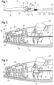
- FIG. 1 shows a system for deploying an implant according to an embodiment of the invention.
- a handle 12 is provided that comprises a first component 13 and a second component 15 that are arranged on top of each other and that are connected to one another.
- a flexible tip 17 is provided at one end of the handle 12.
- a catheter 14 that is suitable for insertion into a patient's vasculature is arranged.
- This catheter 14 can be advanced through a patient's vasculature and can provide, at the distal end thereof, implant such as a TIPS stent graft.
- the catheter 14 has provided thereon an implant holding portion (not shown) at the distal end thereof as well as an implant retaining sheath (not shown) that covers the implant holding portion.
- the handle 12 has provided on its upper surface a recess 33 that is arranged so that a surgeon can rest his or her thumb thereon.
- two protrusions 35 are provided that are arranged so as to help the surgeon in holding the device and the handle and to prevent it from slipping.
- a surgeon can grip with his or her hand around handle 12 so that his or her thumb rests on the recess 33 whilst the remaining fingers are arranged between the protrusions 35 so that the handle 12 is securely held.
- the protrusions 35 are provided at two longitudinal spaced apart positions of the handle 12.
- a thumbwheel 22 is arranged on the handle 12 so that it sticks out of an opening of the handle 12 that is provided inside the recess 33.
- the thumbwheel 22 has a structured surface that increases friction thereof so as to make operating it easier.
- the thumbwheel 22 is coupled to a spindle (not shown) that is, in turn, coupled to the pull tab 16 that will be discussed further below with reference to Figures 2-4 .
- This pull tab 16 is coupled to the implant retaining sheath so that a proximal movement of the pull tab 16 will pull the implant retaining sheath proximally to thus uncover the implant holding portion and to thus deploy an implant that is held at the implant holding portion.
- the pull tab 16 will be wound onto the spindle so that the pull tab 16 is pulled proximally (to the left hand side in Figure 1 ).
- a first release mechanism 28 and a second release mechanism 24 are provided.
- the first release mechanism 28 is to be actuated by means of a button whilst the second release mechanism is operable by means of a slider.
- a structure to be discussed below with reference to Figure 2-4 will block a withdrawal of the implant retaining sheath so that the implant holding portion cannot even be partially uncovered. That is, unless the second release mechanism 24 has been actuated, an implant provided at the implant portion cannot even be partially deployed.
- the position A denotes the position up to which the implant retaining sheath extends when the implant holding portion is fully covered. This position corresponds to the position where the further withdrawal of the pull tab 16 is blocked by means of the second release mechanism 24 not being actuated.
- the implant retaining sheath can be pulled back over a distance denoted by the letter "D". This partial withdrawal corresponds to only the uncovered portion of, e.g., a TIPS stent graft being exposed to the patient's body.
- the portion denoted by E corresponds to a sufficiently full withdrawal of the implant retaining sheath that the entirety of the implant holding portion (and thus of the implant) is uncovered so that the implant can be deployed. This would correspond to the full deployment configuration.
- the portion denoted by C is that portion of the catheter 14 that is not used for carrying the implant. That is, this portion serves to provide enough of a length of the catheter 14 so as to reach the deployment position of the implant.
- the catheter 14 can have provided therein a lumen suitable for leading a guidewire therethrough.
- This guidewire can extend, at the proximal end of the handle 12, through a connector 19 that can be a Luer connector.
- Figure 2 shows an inside view of the lower part 13 of the handle 12 in a configuration where the implant retaining sheath extends up to the point A shown in Figure 1 . That is, the implant holding portion is fully covered.
- the lower part 13 of the handle 12 is made of a plastic shell that has a semi-tubular shape that bulges out when going from the distal end 50 towards the central portion. This allows for ergonomically gripping the handle 12.
- a hemispherical cut out 32 is provided through which the pull tab 16 extends. This pull tab 16 is led through the interior of the lower part 13 and is to be rolled up on a spindle (not shown) attached to thumbwheel 22.
- reinforcing ribs 32 that serves so as to provide mechanical stability to the lower part 13.
- Those reinforcing walls 32 have a notch through which the pull tab 16 is led. That is, those notches serve to stabilise the path of the pull tab 16.
- a metallic plate 30 having a hole provided therein through which the pull tab 16 is led. Also this plate 16 serves to stabilise the path taken by the pull tab 16.
- This plate 30 is attached (clipped) to one of the ribs 32.
- a leaf spring 20 that is, at one of its ends, held by ribs 34 provided on a wall of the lower part 13.
- This leaf spring 20 is bent. Its bent portion abuts against an engagement feature 18 in the form of a ring like protrusion fixedly arranged on the pull tab 16.
- the bent portion of the leaf spring 20 abuts against the proximal-most portion of the engagement feature 18 so that it prevents a proximal movement of the engagement feature 18. In turn, this prevents a proximal movement of the pull tab 16.
- the leaf spring 20 is coupled to the slider 24 so that a sliding movement of the slider 24 will bend the leaf spring 20 so that the bent portion gets out of engagement with the engagement feature 18.
- the first interference feature 26 that has the shape of a U-shaped plastic plate that is coupled to a pushbutton 28.
- the pull tab 16 is led through the recess of the U-shaped plate 26.
- the pushbutton 28 is depressed, the U-shaped plate 26 is pushed down sufficiently far that the pull tab 16 no longer extends through the recess of the U-shaped plate 26.
- the recess of the U-shaped plate 26 is sized so that the engagement feature 18 cannot fit through it so that the engagement between the engagement feature 18 and the U-shaped plate 26 blocks a movement of the engagement feature 18 through that recess whilst being sufficiently wide to allow the rest of the pull tab 16 to freely pass through it.
- Figure 3 shows a configuration where the engagement between the second interference feature in the form of the leaf spring 20 and the engagement feature 18 had been released and where the pull tab 16 has been pulled proximally so that the implant retaining sheath has moved across the portion D in Figure 1 .
- the engagement feature 18 now abuts against the first interference feature 26. Since the pushbutton 28 has not been depressed, a proximal movement of the engagement feature 18 is prevented by that abutment.
- the pushbutton 28 has been depressed, as indicated by an arrow, so that there is now no longer an engagement between the first interference feature 26 and the engagement feature 18. Accordingly, it is possible to pull the pull tab 16 proximally so that also the engagement feature 18 can now be pulsed to a position that is proximal to now arranged proximally of the first interference feature 26. In that configuration, the implant retaining sheath can be moved across the region E shown in Figure 1 to fully deploy the implant that is provided on the implant holding portion.
- the surgeon could ensure that the flared uncovered portion of the TIPS stent graft is arranged in the portal vein, for example using X-ray imaging of markers that are provided on the TIPS stent graft. The surgeon could then feel that the flared portion is completely arranged inside the portal vein by noticing the flared portion abutting against the junction between the TIPS shunt and the portal vein (as a mechanical resistance against proximal withdrawal of the TIPS stent graft to be deployed). Accordingly, since the surgeon knows that only the uncovered portion has been uncovered but that this portion has been uncovered completely, a highly accurate and user-friendly positioning of the TIPS stent graft is possible.
Landscapes
- Health & Medical Sciences (AREA)
- Engineering & Computer Science (AREA)
- Biomedical Technology (AREA)
- Heart & Thoracic Surgery (AREA)
- Public Health (AREA)
- Transplantation (AREA)
- Cardiology (AREA)
- Veterinary Medicine (AREA)
- Oral & Maxillofacial Surgery (AREA)
- Vascular Medicine (AREA)
- Life Sciences & Earth Sciences (AREA)
- Animal Behavior & Ethology (AREA)
- General Health & Medical Sciences (AREA)
- Gastroenterology & Hepatology (AREA)
- Pulmonology (AREA)
- Prostheses (AREA)
- Media Introduction/Drainage Providing Device (AREA)
- Electrotherapy Devices (AREA)
Claims (10)
- System (10) zum Einsetzen eines Implantats, wobei das System Folgendes umfasst:- einen Griff (12),- einen Katheter (14), der sich vom Griff (12) erstreckt, wobei der Katheter angeordnet ist zum Halten eines Implantats an einem Halteabschnitt an einem distalen Ende des Katheters,- eine Implantatrückhaltehülle, wobei die Implantatrückhaltehülle angeordnet ist, um den Implantathalteabschnitt zu umgeben, um ein Implantat, das an dem Implantathalteabschnitt angeordnet ist, zurückzuhalten,- eine Zuglasche (16), wobei die Zuglasche (16) mit der Implantatrückhaltehülle verbunden ist, so dass ein proximaler Zug an der Zuglasche die Implantatrückhaltehülle zurückzieht, um ein Implantat freizugeben, das an dem Implantathalteabschnitt angeordnet ist,wobei die Zuglasche (16) weiter ein Eingreifmerkmal (18) umfasst, das auf der Zuglasche (16) angeordnet ist und das proximal bewegt wird, wenn die Zuglasche (16) proximal bewegt wird, wobei das Eingreifmerkmal (18) angeordnet ist zum Eingreifen in ein erstes Interferenzmerkmal (26), das an einer ersten festen Längsposition an dem System zum Einsetzen des Implantats angeordnet ist,wobei ein Eingreifen zwischen dem Eingreifmerkmal (18) und dem ersten Interferenzmerkmal (26) taktile Rückmeldung an einen Benutzer des Systems bereitstellt, dass die Implantatrückhaltehülle um einen voreingestellten Abstand zurückgezogen wurde, weiter umfassend einen Zuglaschenrückziehmechanismus,wobei der Zuglaschenrückziehmechanismus angeordnet ist zum proximalen Ziehen der Zuglasche (16), um ein Implantat freizugeben, das an dem Implantathalteabschnitt angeordnet ist, wobei der Zuglaschenrückziehmechanismus ein Daumenrad (22) umfasst, das mit einer Spindel gekoppelt ist, wobei die Spindel angeordnet ist zum Aufziehen der Zuglasche (16), um einen proximalen Zug auf die Zuglasche (16) auszuüben.
- System nach einem der vorstehenden Ansprüche, wobei die taktile Rückmeldung ein Blockieren von weiterem Zurückziehen der Zuglasche (16) ist.
- System nach Anspruch 2, wobei das System weiter einen ersten Freigabemechanismus (28) zum selektiven Freigeben des Blockierens von weiterem Zurückziehen der Zuglasche (16) umfasst, wobei der erste Freigabemechanismus (28) optional durch einen benutzerbetätigbaren Druckknopf betätigt werden kann.
- System nach einem der vorstehenden Ansprüche, wobei das Eingreifmerkmal (18) einen Vorsprung umfasst, der fest auf der Zuglasche (16) bereitgestellt ist, und wobei das erste Interferenzmerkmal (26) eine Öffnung umfasst, die innerhalb des Griffs (12) bereitgestellt ist, wobei die Öffnung so bemessen ist, dass der Vorsprung in die Grenzen der Öffnung eingreift, um taktile Rückmeldung an den Benutzer bereitzustellen.
- System nach einem der vorstehenden Ansprüche, weiter umfassend ein zweites Interferenzmerkmal (20), das an einer zweiten festen Längsposition an dem System zum Einsetzen des Implantats angeordnet ist, wobei das Eingreifmerkmal (18) angeordnet ist zum Eingreifen in das zweite Interferenzmerkmal (20), um taktile Rückmeldung an den Benutzer bereitzustellen, wobei die taktile Rückmeldung optional ein Blockieren von Zurückziehen der Zuglasche (16) ist.
- System nach Anspruch 5, wobei das System weiter einen zweiten Freigabemechanismus (24) zum selektiven Freigeben des Blockierens von Zurückziehen der Zuglasche (16) durch das Eingreifen zwischen dem zweiten Interferenzmerkmal (20) und dem Eingreifmerkmal (18) umfasst, wobei der zweite Freigabemechanismus (24) optional mittels eines Schiebers betätigt werden kann.
- System nach Anspruch 5 oder 6, wobei das Eingreifen zwischen dem zweiten Interferenzmerkmal (20) und dem Eingreifmerkmal (18) vollständigem Abdecken des Implantathalteabschnitts durch die Implantatrückhaltehülle entspricht.
- System nach einem der vorstehenden Ansprüche, wobei das System weiter ein Implantat, optional einen Stent-Graft, optionaler einen TIPS-Stent-Graft umfasst, der an dem Implantathalteabschnitt angeordnet ist.
- System nach Anspruch 8, wobei das Implantat ein selbstexpandierendes Implantat ist.
- System nach Anspruch 8 oder 9, wobei das Eingreifen zwischen dem Eingreifmerkmal (18) und dem ersten Interferenzmerkmal (26) einem partiellen Einsetzen des Implantats entspricht.
Priority Applications (1)
| Application Number | Priority Date | Filing Date | Title |
|---|---|---|---|
| EP24181074.6A EP4403135B1 (de) | 2020-10-19 | 2020-10-19 | System zum einsetzen eines implantats |
Applications Claiming Priority (1)
| Application Number | Priority Date | Filing Date | Title |
|---|---|---|---|
| PCT/EP2020/079338 WO2022083843A1 (en) | 2020-10-19 | 2020-10-19 | System for deploying an implant |
Related Child Applications (2)
| Application Number | Title | Priority Date | Filing Date |
|---|---|---|---|
| EP24181074.6A Division EP4403135B1 (de) | 2020-10-19 | 2020-10-19 | System zum einsetzen eines implantats |
| EP24181074.6A Division-Into EP4403135B1 (de) | 2020-10-19 | 2020-10-19 | System zum einsetzen eines implantats |
Publications (3)
| Publication Number | Publication Date |
|---|---|
| EP4228559A1 EP4228559A1 (de) | 2023-08-23 |
| EP4228559B1 true EP4228559B1 (de) | 2024-09-18 |
| EP4228559C0 EP4228559C0 (de) | 2024-09-18 |
Family
ID=73131683
Family Applications (2)
| Application Number | Title | Priority Date | Filing Date |
|---|---|---|---|
| EP24181074.6A Active EP4403135B1 (de) | 2020-10-19 | 2020-10-19 | System zum einsetzen eines implantats |
| EP20801166.8A Active EP4228559B1 (de) | 2020-10-19 | 2020-10-19 | System zum einsetzen eines implantats |
Family Applications Before (1)
| Application Number | Title | Priority Date | Filing Date |
|---|---|---|---|
| EP24181074.6A Active EP4403135B1 (de) | 2020-10-19 | 2020-10-19 | System zum einsetzen eines implantats |
Country Status (8)
| Country | Link |
|---|---|
| US (1) | US20230381004A1 (de) |
| EP (2) | EP4403135B1 (de) |
| JP (1) | JP2024501099A (de) |
| CN (1) | CN116546944A (de) |
| AU (1) | AU2020473550A1 (de) |
| CA (1) | CA3198962A1 (de) |
| ES (1) | ES2989946T3 (de) |
| WO (1) | WO2022083843A1 (de) |
Families Citing this family (1)
| Publication number | Priority date | Publication date | Assignee | Title |
|---|---|---|---|---|
| WO2025239886A1 (en) | 2024-05-14 | 2025-11-20 | Angiomed Gmbh & Co. Medizintechnik Kg | Systems and methods for an intraluminal prosthesis having a sleeve member heat tacked |
Family Cites Families (10)
| Publication number | Priority date | Publication date | Assignee | Title |
|---|---|---|---|---|
| AU3095301A (en) * | 2000-01-31 | 2001-08-07 | Advanced Cardiovascular Systems Inc. | Self-expanding stent with enhanced delivery precision and stent delivery system |
| GB0615658D0 (en) | 2006-08-07 | 2006-09-13 | Angiomed Ag | Hand-held actuator device |
| AU2011296277B2 (en) * | 2010-09-01 | 2014-10-23 | Medtronic Inc. | Single handed deployment handle |
| EP2428189A1 (de) * | 2010-09-10 | 2012-03-14 | Symetis Sa | Kathetereinbringungssystem für ein Stentventil |
| EP2680915B1 (de) * | 2011-03-01 | 2021-12-22 | Endologix LLC | Kathetersystem |
| US8852258B2 (en) * | 2011-10-24 | 2014-10-07 | Novostent Corporation | Catheter assembly with user-assisting handle |
| US9131926B2 (en) * | 2011-11-10 | 2015-09-15 | Boston Scientific Scimed, Inc. | Direct connect flush system |
| US9849016B2 (en) * | 2014-04-04 | 2017-12-26 | W. L. Gore & Associates, Inc. | Method of manufacturing a deployment handle of a medical device deployment system |
| WO2018067537A1 (en) * | 2016-10-07 | 2018-04-12 | Pq Bypass Inc. | Systems and methods for delivering stent grafts |
| IL270209B2 (en) * | 2017-09-13 | 2023-10-01 | Cardinal Health 515 Gmbh | A stent for the coronary artery with a fast sliding catheter and with a slow control device |
-
2020
- 2020-10-19 EP EP24181074.6A patent/EP4403135B1/de active Active
- 2020-10-19 AU AU2020473550A patent/AU2020473550A1/en active Pending
- 2020-10-19 ES ES20801166T patent/ES2989946T3/es active Active
- 2020-10-19 CN CN202080107510.2A patent/CN116546944A/zh active Pending
- 2020-10-19 CA CA3198962A patent/CA3198962A1/en active Pending
- 2020-10-19 JP JP2023523553A patent/JP2024501099A/ja active Pending
- 2020-10-19 EP EP20801166.8A patent/EP4228559B1/de active Active
- 2020-10-19 US US18/032,800 patent/US20230381004A1/en active Pending
- 2020-10-19 WO PCT/EP2020/079338 patent/WO2022083843A1/en not_active Ceased
Also Published As
| Publication number | Publication date |
|---|---|
| CN116546944A (zh) | 2023-08-04 |
| US20230381004A1 (en) | 2023-11-30 |
| WO2022083843A1 (en) | 2022-04-28 |
| EP4403135A2 (de) | 2024-07-24 |
| EP4228559A1 (de) | 2023-08-23 |
| AU2020473550A1 (en) | 2023-06-22 |
| JP2024501099A (ja) | 2024-01-11 |
| EP4403135B1 (de) | 2025-11-26 |
| EP4403135A3 (de) | 2024-09-25 |
| ES2989946T3 (es) | 2024-11-28 |
| EP4228559C0 (de) | 2024-09-18 |
| CA3198962A1 (en) | 2022-04-28 |
| EP4403135C0 (de) | 2025-11-26 |
Similar Documents
| Publication | Publication Date | Title |
|---|---|---|
| US8298276B2 (en) | Stent delivery system, stent placement method, and stent attachment method | |
| JP5226252B2 (ja) | ガイドカテーテルおよびステントデリバリーシステム | |
| AU766325B2 (en) | Stent delivery system for prevention of kinking, and method of loading and using same | |
| US10292850B2 (en) | Deployment handle for a prosthesis delivery device | |
| US20130035636A1 (en) | Delivery and Deployment Catheter for an Implantable Medical Device | |
| EP1701675B1 (de) | Griff für ein implantatablagesystem und anwendungsverfahren | |
| US20110034987A1 (en) | Roll sleeve mechanism for proximal release stent | |
| EP3143968A1 (de) | Protheseneinsatzvorrichtung | |
| US8092468B2 (en) | Deployment handle for an implant deployment device | |
| EP1200017B1 (de) | Stentanbringungskatheter mit vorrichtung zum trennen einer hülle | |
| EP1913906B1 (de) | Stenteinführungssystem | |
| US11534320B2 (en) | Handle for a catheter and corresponding catheter | |
| EP3040058A1 (de) | Einsatzgriff für ausgabevorrichtung mit mechanismus zum schnellen abnehmen einer prothese und zur erneuten umhüllung einer vorrichtungsspitze | |
| JPH11512318A (ja) | ステント・デリバリ・システム | |
| EP1954220B1 (de) | Gerät und verfahren zur abgabe einer ausgekleideten intraluminalen prothese | |
| EP4228559B1 (de) | System zum einsetzen eines implantats | |
| US11166833B2 (en) | Line pull assembly for a prosthetic delivery device | |
| US11051961B2 (en) | Deployment handle with stabilizing rail for a pre-loaded prosthesis delivery device | |
| US20240122601A1 (en) | Embolic coil detachment coupler mechanism |
Legal Events
| Date | Code | Title | Description |
|---|---|---|---|
| STAA | Information on the status of an ep patent application or granted ep patent |
Free format text: STATUS: UNKNOWN |
|
| STAA | Information on the status of an ep patent application or granted ep patent |
Free format text: STATUS: THE INTERNATIONAL PUBLICATION HAS BEEN MADE |
|
| PUAI | Public reference made under article 153(3) epc to a published international application that has entered the european phase |
Free format text: ORIGINAL CODE: 0009012 |
|
| STAA | Information on the status of an ep patent application or granted ep patent |
Free format text: STATUS: REQUEST FOR EXAMINATION WAS MADE |
|
| 17P | Request for examination filed |
Effective date: 20230512 |
|
| AK | Designated contracting states |
Kind code of ref document: A1 Designated state(s): AL AT BE BG CH CY CZ DE DK EE ES FI FR GB GR HR HU IE IS IT LI LT LU LV MC MK MT NL NO PL PT RO RS SE SI SK SM TR |
|
| DAV | Request for validation of the european patent (deleted) | ||
| DAX | Request for extension of the european patent (deleted) | ||
| GRAP | Despatch of communication of intention to grant a patent |
Free format text: ORIGINAL CODE: EPIDOSNIGR1 |
|
| STAA | Information on the status of an ep patent application or granted ep patent |
Free format text: STATUS: GRANT OF PATENT IS INTENDED |
|
| INTG | Intention to grant announced |
Effective date: 20240502 |
|
| GRAS | Grant fee paid |
Free format text: ORIGINAL CODE: EPIDOSNIGR3 |
|
| GRAA | (expected) grant |
Free format text: ORIGINAL CODE: 0009210 |
|
| STAA | Information on the status of an ep patent application or granted ep patent |
Free format text: STATUS: THE PATENT HAS BEEN GRANTED |
|
| RAP3 | Party data changed (applicant data changed or rights of an application transferred) |
Owner name: ANGIOMED GMBH & CO. MEDIZINTECHNIK KG |
|
| AK | Designated contracting states |
Kind code of ref document: B1 Designated state(s): AL AT BE BG CH CY CZ DE DK EE ES FI FR GB GR HR HU IE IS IT LI LT LU LV MC MK MT NL NO PL PT RO RS SE SI SK SM TR |
|
| REG | Reference to a national code |
Ref country code: GB Ref legal event code: FG4D |
|
| REG | Reference to a national code |
Ref country code: CH Ref legal event code: EP |
|
| REG | Reference to a national code |
Ref country code: IE Ref legal event code: FG4D |
|
| REG | Reference to a national code |
Ref country code: DE Ref legal event code: R096 Ref document number: 602020038022 Country of ref document: DE |
|
| U01 | Request for unitary effect filed |
Effective date: 20240927 |
|
| U07 | Unitary effect registered |
Designated state(s): AT BE BG DE DK EE FI FR IT LT LU LV MT NL PT RO SE SI Effective date: 20241023 |
|
| REG | Reference to a national code |
Ref country code: ES Ref legal event code: FG2A Ref document number: 2989946 Country of ref document: ES Kind code of ref document: T3 Effective date: 20241128 |
|
| U20 | Renewal fee for the european patent with unitary effect paid |
Year of fee payment: 5 Effective date: 20241107 |
|
| PG25 | Lapsed in a contracting state [announced via postgrant information from national office to epo] |
Ref country code: NO Free format text: LAPSE BECAUSE OF FAILURE TO SUBMIT A TRANSLATION OF THE DESCRIPTION OR TO PAY THE FEE WITHIN THE PRESCRIBED TIME-LIMIT Effective date: 20241218 |
|
| PG25 | Lapsed in a contracting state [announced via postgrant information from national office to epo] |
Ref country code: GR Free format text: LAPSE BECAUSE OF FAILURE TO SUBMIT A TRANSLATION OF THE DESCRIPTION OR TO PAY THE FEE WITHIN THE PRESCRIBED TIME-LIMIT Effective date: 20241219 |
|
| PG25 | Lapsed in a contracting state [announced via postgrant information from national office to epo] |
Ref country code: HR Free format text: LAPSE BECAUSE OF FAILURE TO SUBMIT A TRANSLATION OF THE DESCRIPTION OR TO PAY THE FEE WITHIN THE PRESCRIBED TIME-LIMIT Effective date: 20240918 |
|
| PG25 | Lapsed in a contracting state [announced via postgrant information from national office to epo] |
Ref country code: RS Free format text: LAPSE BECAUSE OF FAILURE TO SUBMIT A TRANSLATION OF THE DESCRIPTION OR TO PAY THE FEE WITHIN THE PRESCRIBED TIME-LIMIT Effective date: 20241218 |
|
| PG25 | Lapsed in a contracting state [announced via postgrant information from national office to epo] |
Ref country code: RS Free format text: LAPSE BECAUSE OF FAILURE TO SUBMIT A TRANSLATION OF THE DESCRIPTION OR TO PAY THE FEE WITHIN THE PRESCRIBED TIME-LIMIT Effective date: 20241218 Ref country code: NO Free format text: LAPSE BECAUSE OF FAILURE TO SUBMIT A TRANSLATION OF THE DESCRIPTION OR TO PAY THE FEE WITHIN THE PRESCRIBED TIME-LIMIT Effective date: 20241218 Ref country code: HR Free format text: LAPSE BECAUSE OF FAILURE TO SUBMIT A TRANSLATION OF THE DESCRIPTION OR TO PAY THE FEE WITHIN THE PRESCRIBED TIME-LIMIT Effective date: 20240918 Ref country code: GR Free format text: LAPSE BECAUSE OF FAILURE TO SUBMIT A TRANSLATION OF THE DESCRIPTION OR TO PAY THE FEE WITHIN THE PRESCRIBED TIME-LIMIT Effective date: 20241219 |
|
| PG25 | Lapsed in a contracting state [announced via postgrant information from national office to epo] |
Ref country code: IS Free format text: LAPSE BECAUSE OF FAILURE TO SUBMIT A TRANSLATION OF THE DESCRIPTION OR TO PAY THE FEE WITHIN THE PRESCRIBED TIME-LIMIT Effective date: 20250118 |
|
| PG25 | Lapsed in a contracting state [announced via postgrant information from national office to epo] |
Ref country code: SM Free format text: LAPSE BECAUSE OF FAILURE TO SUBMIT A TRANSLATION OF THE DESCRIPTION OR TO PAY THE FEE WITHIN THE PRESCRIBED TIME-LIMIT Effective date: 20240918 |
|
| PG25 | Lapsed in a contracting state [announced via postgrant information from national office to epo] |
Ref country code: CZ Free format text: LAPSE BECAUSE OF FAILURE TO SUBMIT A TRANSLATION OF THE DESCRIPTION OR TO PAY THE FEE WITHIN THE PRESCRIBED TIME-LIMIT Effective date: 20240918 Ref country code: PL Free format text: LAPSE BECAUSE OF FAILURE TO SUBMIT A TRANSLATION OF THE DESCRIPTION OR TO PAY THE FEE WITHIN THE PRESCRIBED TIME-LIMIT Effective date: 20240918 |
|
| PG25 | Lapsed in a contracting state [announced via postgrant information from national office to epo] |
Ref country code: SK Free format text: LAPSE BECAUSE OF FAILURE TO SUBMIT A TRANSLATION OF THE DESCRIPTION OR TO PAY THE FEE WITHIN THE PRESCRIBED TIME-LIMIT Effective date: 20240918 |
|
| REG | Reference to a national code |
Ref country code: CH Ref legal event code: PL |
|
| PG25 | Lapsed in a contracting state [announced via postgrant information from national office to epo] |
Ref country code: MC Free format text: LAPSE BECAUSE OF FAILURE TO SUBMIT A TRANSLATION OF THE DESCRIPTION OR TO PAY THE FEE WITHIN THE PRESCRIBED TIME-LIMIT Effective date: 20240918 |
|
| PG25 | Lapsed in a contracting state [announced via postgrant information from national office to epo] |
Ref country code: CH Free format text: LAPSE BECAUSE OF NON-PAYMENT OF DUE FEES Effective date: 20241031 |
|
| PLBE | No opposition filed within time limit |
Free format text: ORIGINAL CODE: 0009261 |
|
| STAA | Information on the status of an ep patent application or granted ep patent |
Free format text: STATUS: NO OPPOSITION FILED WITHIN TIME LIMIT |
|
| 26N | No opposition filed |
Effective date: 20250619 |
|
| PGFP | Annual fee paid to national office [announced via postgrant information from national office to epo] |
Ref country code: GB Payment date: 20250923 Year of fee payment: 6 |
|
| PG25 | Lapsed in a contracting state [announced via postgrant information from national office to epo] |
Ref country code: IE Free format text: LAPSE BECAUSE OF NON-PAYMENT OF DUE FEES Effective date: 20241019 |
|
| U20 | Renewal fee for the european patent with unitary effect paid |
Year of fee payment: 6 Effective date: 20250923 |
|
| PG25 | Lapsed in a contracting state [announced via postgrant information from national office to epo] |
Ref country code: CY Free format text: LAPSE BECAUSE OF FAILURE TO SUBMIT A TRANSLATION OF THE DESCRIPTION OR TO PAY THE FEE WITHIN THE PRESCRIBED TIME-LIMIT; INVALID AB INITIO Effective date: 20201019 |
|
| PGFP | Annual fee paid to national office [announced via postgrant information from national office to epo] |
Ref country code: ES Payment date: 20251103 Year of fee payment: 6 |