EP4228474B1 - Mechanismus zur elektrischen einstellung der position einer arbeitsfläche - Google Patents
Mechanismus zur elektrischen einstellung der position einer arbeitsfläche Download PDFInfo
- Publication number
- EP4228474B1 EP4228474B1 EP21806301.4A EP21806301A EP4228474B1 EP 4228474 B1 EP4228474 B1 EP 4228474B1 EP 21806301 A EP21806301 A EP 21806301A EP 4228474 B1 EP4228474 B1 EP 4228474B1
- Authority
- EP
- European Patent Office
- Prior art keywords
- vertical
- cable
- guiding element
- adjustment mechanism
- vertical guiding
- Prior art date
- Legal status (The legal status is an assumption and is not a legal conclusion. Google has not performed a legal analysis and makes no representation as to the accuracy of the status listed.)
- Active
Links
Images


Classifications
-
- A—HUMAN NECESSITIES
- A47—FURNITURE; DOMESTIC ARTICLES OR APPLIANCES; COFFEE MILLS; SPICE MILLS; SUCTION CLEANERS IN GENERAL
- A47B—TABLES; DESKS; OFFICE FURNITURE; CABINETS; DRAWERS; GENERAL DETAILS OF FURNITURE
- A47B21/00—Tables or desks for office equipment, e.g. typewriters, keyboards
- A47B21/06—Tables or desks for office equipment, e.g. typewriters, keyboards characterised by means for holding, fastening or concealing cables
-
- A—HUMAN NECESSITIES
- A47—FURNITURE; DOMESTIC ARTICLES OR APPLIANCES; COFFEE MILLS; SPICE MILLS; SUCTION CLEANERS IN GENERAL
- A47B—TABLES; DESKS; OFFICE FURNITURE; CABINETS; DRAWERS; GENERAL DETAILS OF FURNITURE
- A47B5/00—Suspended or hinged panels forming a table; Wall tables
-
- A—HUMAN NECESSITIES
- A47—FURNITURE; DOMESTIC ARTICLES OR APPLIANCES; COFFEE MILLS; SPICE MILLS; SUCTION CLEANERS IN GENERAL
- A47B—TABLES; DESKS; OFFICE FURNITURE; CABINETS; DRAWERS; GENERAL DETAILS OF FURNITURE
- A47B9/00—Tables with tops of variable height
- A47B9/04—Tables with tops of variable height with vertical spindle
-
- E—FIXED CONSTRUCTIONS
- E04—BUILDING
- E04B—GENERAL BUILDING CONSTRUCTIONS; WALLS, e.g. PARTITIONS; ROOFS; FLOORS; CEILINGS; INSULATION OR OTHER PROTECTION OF BUILDINGS
- E04B1/00—Constructions in general; Structures which are not restricted either to walls, e.g. partitions, or floors or ceilings or roofs
- E04B1/62—Insulation or other protection; Elements or use of specified material therefor
- E04B1/74—Heat, sound or noise insulation, absorption, or reflection; Other building methods affording favourable thermal or acoustical conditions, e.g. accumulating of heat within walls
- E04B1/82—Heat, sound or noise insulation, absorption, or reflection; Other building methods affording favourable thermal or acoustical conditions, e.g. accumulating of heat within walls specifically with respect to sound only
- E04B1/8218—Heat, sound or noise insulation, absorption, or reflection; Other building methods affording favourable thermal or acoustical conditions, e.g. accumulating of heat within walls specifically with respect to sound only soundproof enclosures
-
- E—FIXED CONSTRUCTIONS
- E04—BUILDING
- E04H—BUILDINGS OR LIKE STRUCTURES FOR PARTICULAR PURPOSES; SWIMMING OR SPLASH BATHS OR POOLS; MASTS; FENCING; TENTS OR CANOPIES, IN GENERAL
- E04H1/00—Buildings or groups of buildings for dwelling or office purposes; General layout, e.g. modular co-ordination or staggered storeys
- E04H1/12—Small buildings or other erections for limited occupation, erected in the open air or arranged in buildings, e.g. kiosks, waiting shelters for bus stops or for filling stations, roofs for railway platforms, watchmen's huts or dressing cubicles
- E04H1/125—Small buildings, arranged in other buildings
-
- E—FIXED CONSTRUCTIONS
- E06—DOORS, WINDOWS, SHUTTERS, OR ROLLER BLINDS IN GENERAL; LADDERS
- E06B—FIXED OR MOVABLE CLOSURES FOR OPENINGS IN BUILDINGS, VEHICLES, FENCES OR LIKE ENCLOSURES IN GENERAL, e.g. DOORS, WINDOWS, BLINDS, GATES
- E06B3/00—Window sashes, door leaves, or like elements for closing wall or like openings; Layout of fixed or moving closures, e.g. windows in wall or like openings; Features of rigidly-mounted outer frames relating to the mounting of wing frames
- E06B3/04—Wing frames not characterised by the manner of movement
- E06B3/06—Single frames
-
- A—HUMAN NECESSITIES
- A47—FURNITURE; DOMESTIC ARTICLES OR APPLIANCES; COFFEE MILLS; SPICE MILLS; SUCTION CLEANERS IN GENERAL
- A47B—TABLES; DESKS; OFFICE FURNITURE; CABINETS; DRAWERS; GENERAL DETAILS OF FURNITURE
- A47B2200/00—General construction of tables or desks
- A47B2200/0035—Tables or desks with features relating to adjustability or folding
- A47B2200/005—Leg adjustment
- A47B2200/0056—Leg adjustment with a motor, e.g. an electric motor
-
- A—HUMAN NECESSITIES
- A47—FURNITURE; DOMESTIC ARTICLES OR APPLIANCES; COFFEE MILLS; SPICE MILLS; SUCTION CLEANERS IN GENERAL
- A47B—TABLES; DESKS; OFFICE FURNITURE; CABINETS; DRAWERS; GENERAL DETAILS OF FURNITURE
- A47B83/00—Combinations comprising two or more pieces of furniture of different kinds
- A47B83/02—Tables combined with seats
- A47B83/023—Booth-type arrangements
Definitions
- the present disclosure generally relates to mechanisms for adjusting work surface position, such as mechanisms for electrically height adjustable sit stand desks.
- the solution also relates to wall structures and tables comprising such mechanism.
- Height adjustable including electrically height adjustable, desks, such as electrically height adjustable sit stand desks, are known in the industry. Typically, height adjustment is effectuated by a height adjustment mechanism.
- An electrical height adjustment mechanism employs a cable or cables to convey electricity and/or electrical signals, for example, between a control unit and a user interface of the electrical height adjustment mechanism.
- an adjustment mechanism assembly for adjusting a work surface position vertically, comprising
- the vertical support member extends vertically from within the vertical guiding element to outside the vertical guiding element. In certain other embodiments, the vertical support member resides completely within the vertical guiding element.
- the vertical support member is preferably arranged parallelly with the vertical guiding element, more preferably the vertical support member is arranged coaxially with the vertical guiding element.
- the work surface support element is arranged to protrude horizontally from within the vertical guiding element between the (top and bottom) ends of the vertical guiding element. In certain embodiments, the work surface support element is configured to move along the vertical guiding element in the longitudinal direction of the vertical guiding element.
- the work surface support element is engaged with the vertical guiding element through a vertically oriented slit in a side of the vertical guiding element.
- the work surface support element is preferably configured to be movable vertically within said vertically oriented slit with electric actuation.
- the height (in the vertical or longitudinal direction) of the vertical guiding element or/and the vertical support member is/are constant. In certain embodiments, the height (in the vertical or longitudinal direction) of the adjustment mechanism assembly is constant.
- the vertical guiding element is a one-piece element.
- the vertical guiding element consists essentially of one vertical guiding member (in contrast of having for example a telescopic structure).
- Said vertical guiding member is preferably a one-piece member, such as a one-piece column.
- the vertical guiding element is formed of a shell of a column (or of an outer shell of a column assembly).
- the work surface support element is adapted to provide support for a work surface, such as a table top.
- the vertical support member is a pipe preferably comprising a vertically extending slit, and the spiraled portion of the cable is housed within the pipe.
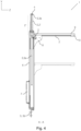
- the vertical guiding element(s) 6 house an actuator such as a motor 31 to effect the movement of the work surface support element(s) 8.
- an actuator may effect the rotational movement of a threaded rod 30 and, consistent with what has been described above, thus effecting the movement of the work surface support element(s) 8.
- the adjustment mechanical assembly 1 may comprise a control unit 7, for example as shown in the embodiment of Figure 1 .
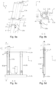
- the vertical guiding element 6 may be a rod-type support member 3,3 a , for example as shown in the embodiment of Figures 1-5 , a pipe-type support member 3,3 b , for example as shown in the embodiment of Figures 9a-9d , an enclosure-type support member 3,3 c , for example as shown in the embodiment of Figures 10a-10d , and/or a wall-or plate-type support member 3,3 d , for example as shown in the embodiment of Figures 11a-11d .
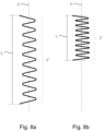
- Such an arrangement also enables a setup in which the entire spiraled portion 2' may reside outside the vertical guiding element 6 in its contracted state (c.f. also Figure 8b ) while allowing it to extend into the inside of the vertical guiding element 6 in its extended state (c.f. also Figure 8a ).
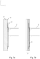
- the mounting support element 5 may be attached to the same vertical end of the vertical guiding element 6 in which said aperture 40 resides.
- the mounting support element 5 may be provided with an aperture that coincides with the aperture 40 of the vertical guiding element 6 (coinciding aperture), for example as shown in the embodiment of Figure 5 .
- reference sign 40 refers to both the aperture of the vertical guiding element 6 and a coinciding aperture of the mounting support element 5.
- the height (in the vertical or longitudinal direction) of the adjustment mechanism assembly 1 is constant.
- the height of the adjustment mechanism assembly 1 is invariable or fixed, i.e. the height of the adjustment mechanism assembly 1 is configured to be unchangeable.
- a gained advantage is that the assembly 1 can be firmly attached to the mounting surface or wall by the vertical guiding element 6, for example, at top and bottom ends of the vertical guiding element 6. Further, a non-contracting vertical guiding element is easier to manufacture.
- the height (in the vertical or longitudinal direction) of the vertical guiding element 6 or/and the vertical support member 3 may be constant (invariable or fixed or configured to be unchangeable).
- the vertical guiding element (or its outer shell) is a one-piece element.
- the vertical guiding element consists essentially of one vertical guiding member.
- Said vertical guiding member is preferably a one-piece member, such as a one-piece column.
- the adjustment mechanism assembly 1 in certain embodiments is non-telescopic.
- the vertical support member 3 may be a rod-type support member 3,3 b , for example as shown in the embodiment of Figure 5 , a pipe-type support member 3,3 b , for example as shown in the embodiment of Figures 9a-9d , an enclosure-type support member 3,3 c , for example as shown in the embodiment of Figures 10a-10c , and/or a wall- or plate-type support member 3,3 d , for example as shown in the embodiments of Figures 11a-11d .
- the vertical support member 3 resides completely within the vertical guiding element 6.
- the vertical support member 3 residing within the vertical guiding element 6 may be any type of vertical support member described in the foregoing.
- the vertical guiding element 6 may be for example a rod-type support member 3,3 a , a pipe-type support member 3,3 b , an enclosure-type support member 3,3 c , and/or a wall-or plate-type support member 3,3 d .
- the vertical guiding element 6 is configured to support the vertical support member 3 to provide positional and alignment stability for the vertical support member 3.
- positional and alignment stability is desirable to prevent the support member 3 from changing position and/or alignment as described in the foregoing.
- an end portion of the vertical support member 3 may be connected to an end portion of the vertical guiding element 6 to provide positional and alignment stability for the vertical support member 3.
- a support element 4 may not be needed.
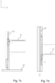
- the upper end of the vertical support member 3 may terminate at and be supported by the top portion (roof) of the vertical guiding element 6, as shown for example in Figure 12c .
- the vertical support member 3 extends vertically from within the vertical guiding element 6 to outside the vertical guiding element 6 positional and alignment stability for the vertical support member 3 may be provided without necessarily needing a support element 4.
- the upper end of the vertical support member 3 may extend to outside the vertical guiding element 6 and terminate at and be supported by a mounting support element 5, as shown for example in Figure 12b .
- end of the support member 3 which resides within the vertical guiding element 6 extends so far, i.e. to such a vertical position, that it still surpasses the work surface support element 8 when the work surface support element 8 is at a position that, in a certain application, is arranged to be its farthest position from the other or opposite end of the vertical support member 3.
- the vertical support member 3 should advantageously be, within the vertical guiding element 6, so long that the spiraled portion 2' of the cable 2 remains supported by the vertical support member 3 even when fully extended so that when the spiraled portion 2' of the cable 2 thereafter contracts, there is no risk of a portion of the spiraled portion 2' of the cable 2 to contract past the vertical support member 3.
- the work surface support element 8 and/or the support element 4 for the vertical support member 3 is (are each) equipped with a strain reliever 41 which provides a fixing point for the cable 2.
- a strain reliever 41 which provides a fixing point for the cable 2.
- the strain reliever 41 at the work surface support element 8 may be configured such that it envelops the cable 2 at this fixing point, for example as shown in the embodiment of Figure 5 , to protect the cable 2 for example from hitting the sides of the slit through which the work surface support element 8 extends and the cable 2 enters into the vertical guiding element 6.
- the strain reliever 41 at the work surface support element 8 may be configured such that it extends inwards into the vertical guiding element 6 and near or adjacent to the slit 42.
- the cable 2 may comprise more than one or several electricity- and/or signal-conveying wires while adhering to the principles described above.
- the cable 2 can take the form of a bundle of individual cables while adhering to the principles described above.
Landscapes
- Engineering & Computer Science (AREA)
- Architecture (AREA)
- Physics & Mathematics (AREA)
- Civil Engineering (AREA)
- Structural Engineering (AREA)
- Acoustics & Sound (AREA)
- Electromagnetism (AREA)
- Building Environments (AREA)
- Casings For Electric Apparatus (AREA)
- Electric Cable Arrangement Between Relatively Moving Parts (AREA)
- Installation Of Indoor Wiring (AREA)
- Tables And Desks Characterized By Structural Shape (AREA)
Claims (14)
- Einstellmechanismusanordnung (1) zum vertikalen Einstellen einer Arbeitsflächenposition, umfassend- ein nicht teleskopierbares vertikales Führungselement (6, 6a, 6b), das aus einem vertikalen Führungselement besteht,- ein Arbeitsflächenstützelement (8, 8a, 8b), das mit dem vertikalen Führungselement in Eingriff steht und so konfiguriert ist, dass es mit elektrischer Betätigung vertikal beweglich ist, wobei das Arbeitsflächenstützelement so angeordnet ist, dass es horizontal aus dem Inneren des vertikalen Führungselements zwischen den Enden des vertikalen Führungselements hervorsteht,- Mittel zur elektrischen Betätigung, die ein Kabel (2) umfassen, und- ein nicht teleskopisches vertikales Stützelement (3, 3a, 3b, 3c, 3d), das sich zumindest teilweise innerhalb des vertikalen Führungselements befindet,- wobei das Kabel zwischen seinen Enden einen spiralförmigen Abschnitt (2') aufweist, der in Bezug auf seine Mittelachse durch das vertikale Stützelement gestützt wird. (2')
- Einstellmechanismusanordnung nach Anspruch 1, wobei sich das vertikale Stützelement vertikal von innerhalb des vertikalen Führungselements nach außerhalb des vertikalen Führungselements erstreckt oder wobei sich das vertikale Stützelement vollständig innerhalb des vertikalen Führungselements befindet.
- Einstellmechanismusanordnung nach Anspruch 1 oder 2, wobei- mindestens ein Teil des spiralförmigen Abschnitts des Kabels außerhalb des vertikalen Führungselements liegt.
- Einstellmechanismusanordnung nach einem der vorhergehenden Ansprüche, wobei- das Kabel so angeordnet ist, dass es in das Innere des vertikalen Führungselements am Arbeitsflächenstützelement eintritt.
- Einstellmechanismusanordnung nach einem der vorhergehenden Ansprüche, wobei- dass der Endabschnitt des vertikalen Stützelements, der sich außerhalb des vertikalen Führungselements befindet, mit einem Stützelement verbunden ist, das so konfiguriert ist, dass es die Bewegung des Endabschnitts des vertikalen Stützelements verhindert.
- Einstellmechanismusanordnung nach einem der vorhergehenden Ansprüche, umfassend- mindestens zwei Zugentlastungen, die so mit dem Kabel verbunden sind, dass der spiralförmige Teil des Kabels zwischen zwei Zugentlastungen liegt.
- Einstellmechanismusanordnung nach Anspruch 6, wobei- das Stützelement eine der beiden Zugentlastungen aufweist,- das Arbeitsflächenstützelement einen weiteren der beiden Zugentlastungen aufweist, und- sich der spiralförmige Abschnitt des Kabels zwischen diesen beiden Zugentlastungen befindet.
- Einstellmechanismusanordnung nach einem der vorhergehenden Ansprüche, wobei- das vertikale Stützelement eine Stange ist und- der spiralförmige Abschnitt des Kabels spiralförmig um die Stange gewickelt ist.
- Einstellmechanismusanordnung nach einem der Ansprüche 1 bis 7, wobei- das vertikale Stützelement ein Rohr mit einem vertikal verlaufenden Schlitz ist, und- der spiralförmige Abschnitt des Kabels im Rohr untergebracht ist.
- Einstellmechanismusanordnung nach einem der Ansprüche 1 bis 7, wobei- das vertikale Stützelement eine Ummantelung mit einem vertikal verlaufenden Schlitz ist, und- der spiralförmige Abschnitt des Kabels im Gehäuse untergebracht ist.
- Einstellmechanismusanordnung nach einem der Ansprüche 1 bis 7, wobei- das vertikale Stützelement eine Platte oder Wand ist, und- sich der spiralförmige Teil des Kabels neben der Platte oder Wand befindet.
- Einstellmechanismusanordnung nach einem der vorhergehenden Ansprüche, umfassend- ein weiteres vertikales Führungselement, und- ein weiteres Arbeitsflächenstützelement, das mit dem weiteren vertikalen Führungselement in Eingriff steht und vertikal beweglich ausgebildet ist.
- Einstellmechanismusanordnung nach einem der vorhergehenden Ansprüche, die mindestens ein Montagestützelement umfasst, das mit dem/den vertikalen Führungselement(en) verbunden ist und zur Montage der Einstellmechanismusanordnung angepasst ist.
- Wandstruktur, die eine Einstellmechanismusanordnung nach einem der vorhergehenden Ansprüche umfasst.
Applications Claiming Priority (3)
| Application Number | Priority Date | Filing Date | Title |
|---|---|---|---|
| FI20206026A FI130488B (en) | 2020-10-19 | 2020-10-19 | Mechanism for electrically adjusting work surface position |
| FI20206274A FI130953B1 (en) | 2020-10-19 | 2020-12-09 | Soundproof booth and wall unit with work table |
| PCT/FI2021/050688 WO2022084581A1 (en) | 2020-10-19 | 2021-10-15 | Mechanism for electrically adjusting work surface position |
Publications (3)
| Publication Number | Publication Date |
|---|---|
| EP4228474A1 EP4228474A1 (de) | 2023-08-23 |
| EP4228474B1 true EP4228474B1 (de) | 2025-07-09 |
| EP4228474C0 EP4228474C0 (de) | 2025-07-09 |
Family
ID=78599038
Family Applications (2)
| Application Number | Title | Priority Date | Filing Date |
|---|---|---|---|
| EP21806301.4A Active EP4228474B1 (de) | 2020-10-19 | 2021-10-15 | Mechanismus zur elektrischen einstellung der position einer arbeitsfläche |
| EP21806303.0A Pending EP4229249A1 (de) | 2020-10-19 | 2021-10-15 | Schalldichte kabine und wandanordnung mit einer arbeitsfläche |
Family Applications After (1)
| Application Number | Title | Priority Date | Filing Date |
|---|---|---|---|
| EP21806303.0A Pending EP4229249A1 (de) | 2020-10-19 | 2021-10-15 | Schalldichte kabine und wandanordnung mit einer arbeitsfläche |
Country Status (3)
| Country | Link |
|---|---|
| US (2) | US12390004B2 (de) |
| EP (2) | EP4228474B1 (de) |
| WO (2) | WO2022084581A1 (de) |
Families Citing this family (4)
| Publication number | Priority date | Publication date | Assignee | Title |
|---|---|---|---|---|
| FI130729B1 (fi) * | 2020-12-09 | 2024-02-15 | Framery Oy | Äänieristetty koppi käsittäen seinäkokoonpanon |
| JP2025537018A (ja) * | 2022-11-25 | 2025-11-12 | フラメリー オーイー | オフィスポッド及び防音壁構造体 |
| WO2025177025A1 (en) * | 2024-02-22 | 2025-08-28 | Steelcase Inc. | Kiosk for short term focus work |
| FI20245214A1 (en) * | 2024-02-22 | 2025-08-23 | Framery Oy | An office module for creating masking sounds |
Citations (1)
| Publication number | Priority date | Publication date | Assignee | Title |
|---|---|---|---|---|
| DE202021101844U1 (de) * | 2021-01-25 | 2021-04-26 | Timotion Technology Co., Ldt. | Hubvorrichtung mit Kabelmanagementkomponente |
Family Cites Families (27)
| Publication number | Priority date | Publication date | Assignee | Title |
|---|---|---|---|---|
| US2927665A (en) | 1955-02-07 | 1960-03-08 | Chicago Metal Mfg Co | Prefabricated sealed building construction |
| US3963094A (en) * | 1974-07-11 | 1976-06-15 | Donley, Miller & Nowikas, Inc. | Muffler structures |
| US4702046A (en) * | 1985-11-08 | 1987-10-27 | General Communications, Inc. | Acoustical wall panel |
| US4987835A (en) * | 1988-11-08 | 1991-01-29 | Edtech Company | Automatic vertically adjustable work surface |
| US5210984A (en) * | 1990-05-02 | 1993-05-18 | Eckel Industries, Inc. | Audiometric booth |
| US6024025A (en) | 1999-02-05 | 2000-02-15 | Equipto | Table lift mechanism |
| US6352037B1 (en) * | 2000-02-28 | 2002-03-05 | Suspa Incorporated | Position sensor holder and cover for motor drive unit |
| US6595144B1 (en) * | 2000-05-17 | 2003-07-22 | Suspa Incorporated | Adjustable leg assembly |
| KR100799284B1 (ko) | 2006-08-22 | 2008-01-30 | 조동환 | 휴대전화 통화 방음부스 |
| EP2301382A1 (de) * | 2009-09-25 | 2011-03-30 | Siemens AB | Teleskopische Säule zur Höheneinstellung |
| US9675170B2 (en) * | 2009-11-28 | 2017-06-13 | Linak A/S | Telescopic column, preferably for furniture |
| NL2004139C2 (nl) | 2010-01-25 | 2011-07-26 | Drentea Kantoormeubelen B V | Verticaal plaatsbaar paneel voorzien van een in hoogte instelbare drager. |
| US8556028B1 (en) * | 2012-04-04 | 2013-10-15 | Braden Manufacturing, Llc | Acoustic module for enclosure panel |
| US9593481B2 (en) * | 2012-06-09 | 2017-03-14 | Dirtt Environmental Solutions, Ltd. | Wall-mounted devices, systems, and methods for selectively positioning objects |
| US9635932B2 (en) * | 2015-06-14 | 2017-05-02 | Assa Group, Inc. | Height adjustable desk system |
| FI131278B1 (en) | 2016-02-02 | 2025-01-24 | Framery Oy | Wall construction |
| KR20170096410A (ko) | 2016-02-16 | 2017-08-24 | (주)성일인터내셔널 | 스마트 스터디 부스 |
| MX2017012175A (es) | 2016-09-26 | 2018-06-06 | Norman R Byrne | Sistema de cordón para mobiliario de altura ajustable. |
| US9655438B1 (en) * | 2016-10-13 | 2017-05-23 | S&S X-Ray Products, Inc. | Ergonomic two-tier work station with height-adjustable work platforms |
| US9723920B1 (en) * | 2017-01-06 | 2017-08-08 | Strength Master Fitness Tech Co., Ltd. | Height-adjustable table with concealed wiring design |
| US10334948B2 (en) * | 2017-05-14 | 2019-07-02 | Loctek Inc. | Electric shelf |
| WO2018213062A1 (en) | 2017-05-19 | 2018-11-22 | Dirtt Environmental Solutions, Inc. | Systems and methods for selectively positioning wall-mounted devices |
| US20190119902A1 (en) * | 2017-10-24 | 2019-04-25 | Phonebooths Inc. | Transportable multi-purpose structure |
| CN210195370U (zh) | 2019-05-21 | 2020-03-27 | 杨峰 | 一种具通风的室内隔音电话亭 |
| TWM591113U (zh) * | 2019-11-18 | 2020-02-21 | 可文山 | 組合式遮蔽結構 |
| RU198733U1 (ru) | 2020-04-17 | 2020-07-23 | Общество с ограниченной ответственностью "Рубиус Групп" | Мобильная шумоизолированная кабина |
| CN120957636A (zh) * | 2023-03-17 | 2025-11-14 | 休思乐公司 | 线缆管理装置和方法 |
-
2021
- 2021-10-15 EP EP21806301.4A patent/EP4228474B1/de active Active
- 2021-10-15 EP EP21806303.0A patent/EP4229249A1/de active Pending
- 2021-10-15 WO PCT/FI2021/050688 patent/WO2022084581A1/en not_active Ceased
- 2021-10-15 US US18/032,206 patent/US12390004B2/en active Active
- 2021-10-15 WO PCT/FI2021/050690 patent/WO2022084582A1/en not_active Ceased
- 2021-10-15 US US18/247,763 patent/US12201215B2/en active Active
Patent Citations (1)
| Publication number | Priority date | Publication date | Assignee | Title |
|---|---|---|---|---|
| DE202021101844U1 (de) * | 2021-01-25 | 2021-04-26 | Timotion Technology Co., Ldt. | Hubvorrichtung mit Kabelmanagementkomponente |
Also Published As
| Publication number | Publication date |
|---|---|
| WO2022084581A1 (en) | 2022-04-28 |
| EP4228474A1 (de) | 2023-08-23 |
| WO2022084582A1 (en) | 2022-04-28 |
| US12201215B2 (en) | 2025-01-21 |
| EP4229249A1 (de) | 2023-08-23 |
| EP4228474C0 (de) | 2025-07-09 |
| US20230371683A1 (en) | 2023-11-23 |
| US12390004B2 (en) | 2025-08-19 |
| US20230399842A1 (en) | 2023-12-14 |
Similar Documents
| Publication | Publication Date | Title |
|---|---|---|
| EP4228474B1 (de) | Mechanismus zur elektrischen einstellung der position einer arbeitsfläche | |
| KR101517775B1 (ko) | 안테나 고정용 슬라이드 브라켓 및 이를 사용한 안테나 고정 장치 | |
| CN110934421A (zh) | 高度可调节式桌或台 | |
| US20200085185A1 (en) | Telescopic column with internal cable | |
| JP3174754U (ja) | 自動的に伸縮可能な照明構造 | |
| KR101884013B1 (ko) | 내진 설계를 갖춘 공동주택 전기시설물 | |
| FI130488B (en) | Mechanism for electrically adjusting work surface position | |
| CN108799893B (zh) | 一种节省空间的智能台灯 | |
| JP2020035560A (ja) | 給電装置 | |
| WO2025039785A1 (zh) | 升降立柱及电动升降桌 | |
| CN220694665U (zh) | 升降立柱及电动升降桌 | |
| AU2019360440A1 (en) | Office or laboratory workstation | |
| DE60335054D1 (de) | Binnensaüle für Niederspannungstromverbindung | |
| KR20110008391A (ko) | 이동 벽체용 전기 통신 모듈 | |
| JP6723846B2 (ja) | 天板付家具 | |
| CN220777702U (zh) | 一种内走线升降立柱及电动升降桌 | |
| JPS6021850Y2 (ja) | 導電伸縮支柱 | |
| KR200365974Y1 (ko) | 파티션 연결장치 | |
| CN223471929U (zh) | 一种便于线束布设的低压电容柜 | |
| CN117322726A (zh) | 一种内走线升降立柱及电动升降桌 | |
| JP6641621B2 (ja) | 天板昇降式什器 | |
| CN222319940U (zh) | 一种可调节式电流互感器 | |
| JPS6348027Y2 (de) | ||
| CN219939979U (zh) | 高度可调节的桌子及桌腿 | |
| CN214332539U (zh) | 一种太阳能灯安装结构 |
Legal Events
| Date | Code | Title | Description |
|---|---|---|---|
| STAA | Information on the status of an ep patent application or granted ep patent |
Free format text: STATUS: UNKNOWN |
|
| STAA | Information on the status of an ep patent application or granted ep patent |
Free format text: STATUS: THE INTERNATIONAL PUBLICATION HAS BEEN MADE |
|
| PUAI | Public reference made under article 153(3) epc to a published international application that has entered the european phase |
Free format text: ORIGINAL CODE: 0009012 |
|
| STAA | Information on the status of an ep patent application or granted ep patent |
Free format text: STATUS: REQUEST FOR EXAMINATION WAS MADE |
|
| 17P | Request for examination filed |
Effective date: 20230421 |
|
| AK | Designated contracting states |
Kind code of ref document: A1 Designated state(s): AL AT BE BG CH CY CZ DE DK EE ES FI FR GB GR HR HU IE IS IT LI LT LU LV MC MK MT NL NO PL PT RO RS SE SI SK SM TR |
|
| DAV | Request for validation of the european patent (deleted) | ||
| DAX | Request for extension of the european patent (deleted) | ||
| STAA | Information on the status of an ep patent application or granted ep patent |
Free format text: STATUS: EXAMINATION IS IN PROGRESS |
|
| 17Q | First examination report despatched |
Effective date: 20240912 |
|
| GRAP | Despatch of communication of intention to grant a patent |
Free format text: ORIGINAL CODE: EPIDOSNIGR1 |
|
| STAA | Information on the status of an ep patent application or granted ep patent |
Free format text: STATUS: GRANT OF PATENT IS INTENDED |
|
| INTG | Intention to grant announced |
Effective date: 20250428 |
|
| GRAS | Grant fee paid |
Free format text: ORIGINAL CODE: EPIDOSNIGR3 |
|
| GRAA | (expected) grant |
Free format text: ORIGINAL CODE: 0009210 |
|
| STAA | Information on the status of an ep patent application or granted ep patent |
Free format text: STATUS: THE PATENT HAS BEEN GRANTED |
|
| RIN1 | Information on inventor provided before grant (corrected) |
Inventor name: VILERMO, MIIKA Inventor name: KOPF, MARKUS |
|
| AK | Designated contracting states |
Kind code of ref document: B1 Designated state(s): AL AT BE BG CH CY CZ DE DK EE ES FI FR GB GR HR HU IE IS IT LI LT LU LV MC MK MT NL NO PL PT RO RS SE SI SK SM TR |
|
| REG | Reference to a national code |
Ref country code: GB Ref legal event code: FG4D |
|
| REG | Reference to a national code |
Ref country code: CH Ref legal event code: EP |
|
| REG | Reference to a national code |
Ref country code: IE Ref legal event code: FG4D |
|
| REG | Reference to a national code |
Ref country code: DE Ref legal event code: R096 Ref document number: 602021033890 Country of ref document: DE |
|
| U01 | Request for unitary effect filed |
Effective date: 20250710 |
|
| U07 | Unitary effect registered |
Designated state(s): AT BE BG DE DK EE FI FR IT LT LU LV MT NL PT RO SE SI Effective date: 20250716 |
|
| U20 | Renewal fee for the european patent with unitary effect paid |
Year of fee payment: 5 Effective date: 20250908 |