EP4227529A1 - Vacuum exhaust system - Google Patents
Vacuum exhaust system Download PDFInfo
- Publication number
- EP4227529A1 EP4227529A1 EP21877529.4A EP21877529A EP4227529A1 EP 4227529 A1 EP4227529 A1 EP 4227529A1 EP 21877529 A EP21877529 A EP 21877529A EP 4227529 A1 EP4227529 A1 EP 4227529A1
- Authority
- EP
- European Patent Office
- Prior art keywords
- pump
- vacuum
- exhaust
- passage
- bypass valve
- Prior art date
- Legal status (The legal status is an assumption and is not a legal conclusion. Google has not performed a legal analysis and makes no representation as to the accuracy of the status listed.)
- Pending
Links
Images


Classifications
-
- F—MECHANICAL ENGINEERING; LIGHTING; HEATING; WEAPONS; BLASTING
- F04—POSITIVE - DISPLACEMENT MACHINES FOR LIQUIDS; PUMPS FOR LIQUIDS OR ELASTIC FLUIDS
- F04B—POSITIVE-DISPLACEMENT MACHINES FOR LIQUIDS; PUMPS
- F04B41/00—Pumping installations or systems specially adapted for elastic fluids
- F04B41/06—Combinations of two or more pumps
-
- G—PHYSICS
- G05—CONTROLLING; REGULATING
- G05D—SYSTEMS FOR CONTROLLING OR REGULATING NON-ELECTRIC VARIABLES
- G05D7/00—Control of flow
- G05D7/06—Control of flow characterised by the use of electric means
- G05D7/0617—Control of flow characterised by the use of electric means specially adapted for fluid materials
- G05D7/0629—Control of flow characterised by the use of electric means specially adapted for fluid materials characterised by the type of regulator means
- G05D7/0688—Control of flow characterised by the use of electric means specially adapted for fluid materials characterised by the type of regulator means by combined action on throttling means and flow sources
-
- F—MECHANICAL ENGINEERING; LIGHTING; HEATING; WEAPONS; BLASTING
- F04—POSITIVE - DISPLACEMENT MACHINES FOR LIQUIDS; PUMPS FOR LIQUIDS OR ELASTIC FLUIDS
- F04B—POSITIVE-DISPLACEMENT MACHINES FOR LIQUIDS; PUMPS
- F04B37/00—Pumps having pertinent characteristics not provided for in, or of interest apart from, groups F04B25/00 - F04B35/00
- F04B37/10—Pumps having pertinent characteristics not provided for in, or of interest apart from, groups F04B25/00 - F04B35/00 for special use
- F04B37/14—Pumps having pertinent characteristics not provided for in, or of interest apart from, groups F04B25/00 - F04B35/00 for special use to obtain high vacuum
- F04B37/16—Means for nullifying unswept space
-
- F—MECHANICAL ENGINEERING; LIGHTING; HEATING; WEAPONS; BLASTING
- F04—POSITIVE - DISPLACEMENT MACHINES FOR LIQUIDS; PUMPS FOR LIQUIDS OR ELASTIC FLUIDS
- F04B—POSITIVE-DISPLACEMENT MACHINES FOR LIQUIDS; PUMPS
- F04B49/00—Control, e.g. of pump delivery, or pump pressure of, or safety measures for, machines, pumps, or pumping installations, not otherwise provided for, or of interest apart from, groups F04B1/00 - F04B47/00
- F04B49/22—Control, e.g. of pump delivery, or pump pressure of, or safety measures for, machines, pumps, or pumping installations, not otherwise provided for, or of interest apart from, groups F04B1/00 - F04B47/00 by means of valves
- F04B49/24—Bypassing
-
- F—MECHANICAL ENGINEERING; LIGHTING; HEATING; WEAPONS; BLASTING
- F04—POSITIVE - DISPLACEMENT MACHINES FOR LIQUIDS; PUMPS FOR LIQUIDS OR ELASTIC FLUIDS
- F04C—ROTARY-PISTON, OR OSCILLATING-PISTON, POSITIVE-DISPLACEMENT MACHINES FOR LIQUIDS; ROTARY-PISTON, OR OSCILLATING-PISTON, POSITIVE-DISPLACEMENT PUMPS
- F04C23/00—Combinations of two or more pumps, each being of rotary-piston or oscillating-piston type, specially adapted for elastic fluids; Pumping installations specially adapted for elastic fluids; Multi-stage pumps specially adapted for elastic fluids
- F04C23/001—Combinations of two or more pumps, each being of rotary-piston or oscillating-piston type, specially adapted for elastic fluids; Pumping installations specially adapted for elastic fluids; Multi-stage pumps specially adapted for elastic fluids of similar working principle
-
- F—MECHANICAL ENGINEERING; LIGHTING; HEATING; WEAPONS; BLASTING
- F04—POSITIVE - DISPLACEMENT MACHINES FOR LIQUIDS; PUMPS FOR LIQUIDS OR ELASTIC FLUIDS
- F04C—ROTARY-PISTON, OR OSCILLATING-PISTON, POSITIVE-DISPLACEMENT MACHINES FOR LIQUIDS; ROTARY-PISTON, OR OSCILLATING-PISTON, POSITIVE-DISPLACEMENT PUMPS
- F04C23/00—Combinations of two or more pumps, each being of rotary-piston or oscillating-piston type, specially adapted for elastic fluids; Pumping installations specially adapted for elastic fluids; Multi-stage pumps specially adapted for elastic fluids
- F04C23/005—Combinations of two or more pumps, each being of rotary-piston or oscillating-piston type, specially adapted for elastic fluids; Pumping installations specially adapted for elastic fluids; Multi-stage pumps specially adapted for elastic fluids of dissimilar working principle
-
- F—MECHANICAL ENGINEERING; LIGHTING; HEATING; WEAPONS; BLASTING
- F04—POSITIVE - DISPLACEMENT MACHINES FOR LIQUIDS; PUMPS FOR LIQUIDS OR ELASTIC FLUIDS
- F04C—ROTARY-PISTON, OR OSCILLATING-PISTON, POSITIVE-DISPLACEMENT MACHINES FOR LIQUIDS; ROTARY-PISTON, OR OSCILLATING-PISTON, POSITIVE-DISPLACEMENT PUMPS
- F04C25/00—Adaptations of pumps for special use of pumps for elastic fluids
- F04C25/02—Adaptations of pumps for special use of pumps for elastic fluids for producing high vacuum
-
- F—MECHANICAL ENGINEERING; LIGHTING; HEATING; WEAPONS; BLASTING
- F04—POSITIVE - DISPLACEMENT MACHINES FOR LIQUIDS; PUMPS FOR LIQUIDS OR ELASTIC FLUIDS
- F04C—ROTARY-PISTON, OR OSCILLATING-PISTON, POSITIVE-DISPLACEMENT MACHINES FOR LIQUIDS; ROTARY-PISTON, OR OSCILLATING-PISTON, POSITIVE-DISPLACEMENT PUMPS
- F04C28/00—Control of, monitoring of, or safety arrangements for, pumps or pumping installations specially adapted for elastic fluids
- F04C28/02—Control of, monitoring of, or safety arrangements for, pumps or pumping installations specially adapted for elastic fluids specially adapted for several pumps connected in series or in parallel
-
- F—MECHANICAL ENGINEERING; LIGHTING; HEATING; WEAPONS; BLASTING
- F04—POSITIVE - DISPLACEMENT MACHINES FOR LIQUIDS; PUMPS FOR LIQUIDS OR ELASTIC FLUIDS
- F04C—ROTARY-PISTON, OR OSCILLATING-PISTON, POSITIVE-DISPLACEMENT MACHINES FOR LIQUIDS; ROTARY-PISTON, OR OSCILLATING-PISTON, POSITIVE-DISPLACEMENT PUMPS
- F04C28/00—Control of, monitoring of, or safety arrangements for, pumps or pumping installations specially adapted for elastic fluids
- F04C28/06—Control of, monitoring of, or safety arrangements for, pumps or pumping installations specially adapted for elastic fluids specially adapted for stopping, starting, idling or no-load operation
-
- F—MECHANICAL ENGINEERING; LIGHTING; HEATING; WEAPONS; BLASTING
- F04—POSITIVE - DISPLACEMENT MACHINES FOR LIQUIDS; PUMPS FOR LIQUIDS OR ELASTIC FLUIDS
- F04C—ROTARY-PISTON, OR OSCILLATING-PISTON, POSITIVE-DISPLACEMENT MACHINES FOR LIQUIDS; ROTARY-PISTON, OR OSCILLATING-PISTON, POSITIVE-DISPLACEMENT PUMPS
- F04C28/00—Control of, monitoring of, or safety arrangements for, pumps or pumping installations specially adapted for elastic fluids
- F04C28/24—Control of, monitoring of, or safety arrangements for, pumps or pumping installations specially adapted for elastic fluids characterised by using valves controlling pressure or flow rate, e.g. discharge valves or unloading valves
- F04C28/26—Control of, monitoring of, or safety arrangements for, pumps or pumping installations specially adapted for elastic fluids characterised by using valves controlling pressure or flow rate, e.g. discharge valves or unloading valves using bypass channels
-
- F—MECHANICAL ENGINEERING; LIGHTING; HEATING; WEAPONS; BLASTING
- F04—POSITIVE - DISPLACEMENT MACHINES FOR LIQUIDS; PUMPS FOR LIQUIDS OR ELASTIC FLUIDS
- F04B—POSITIVE-DISPLACEMENT MACHINES FOR LIQUIDS; PUMPS
- F04B2205/00—Fluid parameters
- F04B2205/15—By-passing over the pump
-
- F—MECHANICAL ENGINEERING; LIGHTING; HEATING; WEAPONS; BLASTING
- F04—POSITIVE - DISPLACEMENT MACHINES FOR LIQUIDS; PUMPS FOR LIQUIDS OR ELASTIC FLUIDS
- F04C—ROTARY-PISTON, OR OSCILLATING-PISTON, POSITIVE-DISPLACEMENT MACHINES FOR LIQUIDS; ROTARY-PISTON, OR OSCILLATING-PISTON, POSITIVE-DISPLACEMENT PUMPS
- F04C18/00—Rotary-piston pumps specially adapted for elastic fluids
- F04C18/08—Rotary-piston pumps specially adapted for elastic fluids of intermeshing-engagement type, i.e. with engagement of co-operating members similar to that of toothed gearing
- F04C18/12—Rotary-piston pumps specially adapted for elastic fluids of intermeshing-engagement type, i.e. with engagement of co-operating members similar to that of toothed gearing of other than internal-axis type
- F04C18/126—Rotary-piston pumps specially adapted for elastic fluids of intermeshing-engagement type, i.e. with engagement of co-operating members similar to that of toothed gearing of other than internal-axis type with radially from the rotor body extending elements, not necessarily co-operating with corresponding recesses in the other rotor, e.g. lobes, Roots type
-
- F—MECHANICAL ENGINEERING; LIGHTING; HEATING; WEAPONS; BLASTING
- F04—POSITIVE - DISPLACEMENT MACHINES FOR LIQUIDS; PUMPS FOR LIQUIDS OR ELASTIC FLUIDS
- F04C—ROTARY-PISTON, OR OSCILLATING-PISTON, POSITIVE-DISPLACEMENT MACHINES FOR LIQUIDS; ROTARY-PISTON, OR OSCILLATING-PISTON, POSITIVE-DISPLACEMENT PUMPS
- F04C2220/00—Application
- F04C2220/10—Vacuum
-
- H—ELECTRICITY
- H10—SEMICONDUCTOR DEVICES; ELECTRIC SOLID-STATE DEVICES NOT OTHERWISE PROVIDED FOR
- H10P—GENERIC PROCESSES OR APPARATUS FOR THE MANUFACTURE OR TREATMENT OF DEVICES COVERED BY CLASS H10
- H10P72/00—Handling or holding of wafers, substrates or devices during manufacture or treatment thereof
- H10P72/04—Apparatus for manufacture or treatment
- H10P72/0402—Apparatus for fluid treatment
Definitions
- the present invention relates to a vacuum exhaust system, and more particularly, relates to a vacuum exhaust system capable of reducing the size of a pump or a valve, and thinning a pipe diameter, and capable of performing highly efficient exhaust making the best use of exhaust characteristics of pumps from high vacuum to the large flow rate region.
- the semiconductors are manufactured, for instance, by doping a semiconductor substrate having a very high purity with impurities, and thereby imparting electric properties thereto, forming microscopic circuit patterns on semiconductor substrates, and stacking them.
- a vacuum exhaust system to which a pump device including a volume transfer type vacuum pump or a momentum transfer type vacuum pump is applied, has been used.
- manufacturing steps of a semiconductor include a large number of steps of causing various process gases to act on a semiconductor substrate.
- the vacuum exhaust system is used not only for evacuating inside of the vacuum chamber, but also for exhausting the process gases from the inside of the vacuum chamber (see, e.g., PTL 1). Further, the vacuum exhaust system is also used in an electron microscope facility so that environment in the vacuum chamber of an electron microscope or the like is at a high level vacuum state in order to prevent refraction or the like of an electron beam caused by the presence of powder dust, or the like.
- FIG. 3 shows a block view of such a conventional vacuum exhaust system.
- a flow rate of process gas supplied from a gas cylinder 1 is adjusted at a gas flow rate controller 3, and then is charged into a vacuum chamber 5. Thereafter, the process gas that has been used in the vacuum chamber 5 is discharged from the vacuum chamber 5, passes through a regulating valve 7 for regulating the gas flow rate, and reaches a branch pipe 9.
- the passage on the side indicated with A in the drawing of the branch pipe 9 is connected with an inlet port, which is not shown, of a second pump via a passage switching valve 11.
- the passage on the side indicated with B in the drawing of the branch pipe 9 is provided with a passage switching valve 13.
- the outlet port not shown of the second pump is provided with a passage switching valve 15.
- a first pump is connected to the downstream of the passage switching valve 15 and the downstream of the passage switching valve 13 via a branch pipe 17.
- a bypass pipe 21 may be directly connected with the vacuum chamber 5.
- the vacuum exhaust system may increase in size, which may result in difficulty in ensuring a setting space, or an increase in cost.
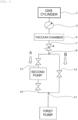
- same elements as those in FIG. 3 are given same reference numerals and signs, and will not be described (the same shall apply hereinafter).
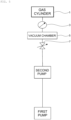
- FIG. 5 shows an example in which the second pump can be operated even in the medium vacuum region, and the second pump is connected in series with a first pump.
- FIG. 6 shows a manner in which an exhaust characteristic of the second pump decreases in the medium vacuum region. Namely, it is indicated that, for the second pump, an effective pumping speed gradually decreases in conjunction with an increase in pressure in the medium vacuum region having a higher pressure than 0.1 [Pa].
- the present invention was completed in view of such conventional problems. It is an object of the present invention to provide a vacuum exhaust system capable of reducing the size of a pump or a valve, and capable of thinning a pipe diameter, and capable of performing highly efficient exhaust making the best use of exhaust characteristics of pumps from high vacuum to a large flow rate region.
- a vacuum exhaust system includes a first pump for performing vacuum exhaust from atmospheric pressure to a medium vacuum region; a second pump connected in series with the first pump, and having a lower ultimate pressure than that of the first pump; and a bypass valve provided in parallel with the second pump via a pipe communicating with an inlet port and an outlet port of the second pump, wherein an exhaust gas from a vacuum chamber is exhausted via bot of a passage of the second pump and a passage of the bypass valve.
- An exhaust gas from the vacuum chamber is exhausted via both of the passage of the second pump and the passage of the bypass valve in addition to the suction of the first pump.
- the bypass valve in a low medium vacuum region, while the first pump and the second pump being operated, the bypass valve is opened, and in medium and high vacuum regions, while the first pump and the second pump being operated, the bypass valve is closed.
- the vacuum exhaust system includes a flow rate measuring means for measuring the flow rate of the exhaust gas flowing in the vacuum chamber; and an opening/closing control means for opening or closing the bypass valve on the basis of the magnitude of the flow rate measured by the flow rate measuring means.
- the bypass valve is opened or closed on the basis of the magnitude of the flow rate measured by the flow rate measuring means.
- the vacuum exhaust system includes an opening degree control means for controlling the degree of opening of the bypass valve, wherein the degree of opening is controlled by the opening degree control means according to at least any one of the flow rate of the exhaust gas flowing in the vacuum chamber and the pressure in an exhaust system.
- the first pump includes a volume transfer type vacuum pump having a large pumping speed in the medium vacuum region.
- the second pump includes a momentum transfer type vacuum pump having a high pumping speed in a high vacuum region, and having an ultimate pressure reaching high vacuum or a lower pressure than the high vacuum.
- the present invention is configured such that the exhaust gas from the vacuum chamber is exhausted via both of the passage of the second pump and the passage of the bypass valve in addition to the suction of the first pump. For this reason, with the vacuum exhaust system, it becomes possible to perform vacuum exhaust making the best use of the exhaust characteristics of both of the second pump and the first pump without increasing the size of the second pump.
- the bypass valve and the pipe diameter can also be configured small.
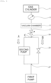
- FIG. 1 shows a block view of a vacuum exhaust system of an embodiment of the present invention.
- the process gas which has been used in a vacuum chamber 5 passes through a regulating valve 7, and reaches a branch pipe 29.
- the passage on the side indicated with A in the drawing of a branch pipe 29 is connected with an inlet port not shown of a second pump.
- the passage on the side indicated with B in the drawing of the branch pipe 29 is provided with a bypass valve 23.
- downstream of the outlet port not shown of the second pump and the downstream of the bypass valve 23 are connected with a first pump via a branch pipe 27.
- the first pump for example, a volume transfer type vacuum pump of a root type, a screw type, a claw type, or the like is used.
- a pump with a high pumping speed in the medium vacuum region, and suitable for exhaust of a large flow rate gas is desirable.
- these may be configured in a multistage form.
- the first pump is large in pump size, and hence may be set outside a clean room.
- the second pump for example, a momentum transfer type vacuum pump of a turbo-molecular pump, a molecular pump (a drag pump of a thread groove type, a Siegbahn type, a Gaede type, or the like), or the like is used.
- the momentum transfer type vacuum pump is operated at a high rotation rate so as to generally effectively apply a momentum to a gas molecule. For this reason, heat generation or a large electric power is required for exhaust of a large flow rate gas in the medium vacuum region. Further, accordingly, the momentum transfer type vacuum pump is not suitable. According to the exhaust principle, in the medium vacuum region, the pumping speed is reduced.
- the second pump is desirably set in the vicinity of the vacuum chamber 5 for acquiring a high vacuum performance.
- the bypass valve 23 is opened. At this step, the gas is exhausted through both of the passage A including the second pump therethrough and the passage B. Then, when exhaust under medium and high vacuum conditions lower than that is performed, the bypass valve 23 is closed, and exhaust is performed through the passage A.
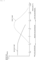
- FIG. 2 shows an exhaust characteristic view of the vacuum exhaust system with the configuration of FIG. 1 .
- the passage B of FIG. 1 includes a pipe thinner than that in each case of FIGS. 3 to 5 .
- the height of the mountain shape of the exhaust characteristic of the passage B is lower than that of the characteristic of the first pump of FIG. 6 .
- the gas is exhausted through both of the passage A and the passage B.
- the pumping speed at a point C in FIG. 1 of the merging point between the passage A and the passage B becomes roughly the total pumping speed of the passage A and the passage B.
- the exhaust characteristic in the low and medium vacuum regions at the point C has the shape having the same height as that of the characteristic of the exhaust gas flowing through the passage switching valve 13 in the case of each configuration of FIGS. 3 to 4 as indicated with the mountain shape of a dotted line in FIG. 2 .
- the gas is exhausted through both of the passage A and the passage B.
- the exhaust characteristic of the system the exhaust characteristic in a mountain shape indicated with a dotted line in FIG. 2 in the low and medium vacuum regions, and the exhaust characteristic that while the effective pumping speed becomes flat in the high vacuum region while attenuating in the low and medium vacuum regions on the passage A side are synthesized as with the continuous transition portion indicated with "aa" in FIG. 2 .
- the bypass valve 23 is switched from open to close. As a result of this, the bypass valve 23 connected with the inlet/outlet port of the second pump is blocked, so that the compression performance in high vacuum possessed by the second pump is obtained.
- the bypass valve 23 is desirably closed. Subsequently, the second pump allows transition at a constant effective pumping speed, leading to a high vacuum state.
- bypass valve 23 and a gas flow rate controller 3 are interlocked, so that the bypass valve 23 is opened at the time of large flow rate, and the bypass valve 23 is closed at the time of small flow rate (or a gas flow rate of zero) requiring high vacuum.
- Control of opening or closing the bypass valve 23 corresponds to the opening/closing control means.
- the vacuum exhaust system enables vacuum exhaust making the best use of both the exhaust characteristics of the second pump and the first pump without increasing the size of the second pump.
- the bypass valve 23 has been described as a valve only to be opened and closed.
- the degree of opening may be regulated according to the gas flow rate and the pressure in the exhaust system, thereby smoothly performing switching.
- Control of the degree of opening of the bypass valve 23 corresponds to the opening degree control means.
- the flow rate is, for example, extracted from the gas flow rate controller 3, and the pressure is extracted from the vacuum chamber 5.
- the second pump, the bypass valve 23, and the pipe diameter can be reduced in size.
- it becomes possible to perform highly efficient exhaust making the best use of the exhaust characteristics of the first and second pumps in from high vacuum to the large flow region.
- vacuum exhaust is performed with the first pump, and the second pump is driven after the pressure in the inside thereof satisfies the operable condition.
- the inlet/outlet port of the second pump may be provided with a valve for maintenance.
- an exhaust path and a valve for roughly evacuating the vacuum chamber 5 from the atmosphere to a prescribed pressure may be set.
- the present invention can be variously modified unless it departs from the spirit of the present invention.
- the embodiments and respective modified examples can be variously combined.
Landscapes
- Engineering & Computer Science (AREA)
- Mechanical Engineering (AREA)
- General Engineering & Computer Science (AREA)
- Physics & Mathematics (AREA)
- General Physics & Mathematics (AREA)
- Automation & Control Theory (AREA)
- Fluid Mechanics (AREA)
- Compressors, Vaccum Pumps And Other Relevant Systems (AREA)
Abstract
Description
- The present invention relates to a vacuum exhaust system, and more particularly, relates to a vacuum exhaust system capable of reducing the size of a pump or a valve, and thinning a pipe diameter, and capable of performing highly efficient exhaust making the best use of exhaust characteristics of pumps from high vacuum to the large flow rate region.
- With recent development of electronics, demand for semiconductors such as a memory and an integrated circuit has been rapidly increasing. The semiconductors are manufactured, for instance, by doping a semiconductor substrate having a very high purity with impurities, and thereby imparting electric properties thereto, forming microscopic circuit patterns on semiconductor substrates, and stacking them.
- Then, such operations are required to be performed in a vacuum chamber in a high vacuum state in order to avoid effects elicited from dust in air, or the like. For exhaust from the vacuum chamber, generally a vacuum exhaust system, to which a pump device including a volume transfer type vacuum pump or a momentum transfer type vacuum pump is applied, has been used.
- Further, manufacturing steps of a semiconductor include a large number of steps of causing various process gases to act on a semiconductor substrate. The vacuum exhaust system is used not only for evacuating inside of the vacuum chamber, but also for exhausting the process gases from the inside of the vacuum chamber (see, e.g., PTL 1). Further, the vacuum exhaust system is also used in an electron microscope facility so that environment in the vacuum chamber of an electron microscope or the like is at a high level vacuum state in order to prevent refraction or the like of an electron beam caused by the presence of powder dust, or the like.
FIG. 3 shows a block view of such a conventional vacuum exhaust system. - In
FIG. 3 , a flow rate of process gas supplied from agas cylinder 1 is adjusted at a gasflow rate controller 3, and then is charged into avacuum chamber 5. Thereafter, the process gas that has been used in thevacuum chamber 5 is discharged from thevacuum chamber 5, passes through a regulatingvalve 7 for regulating the gas flow rate, and reaches abranch pipe 9. The passage on the side indicated with A in the drawing of thebranch pipe 9 is connected with an inlet port, which is not shown, of a second pump via apassage switching valve 11. On the other hand, the passage on the side indicated with B in the drawing of thebranch pipe 9 is provided with apassage switching valve 13. - Then, the outlet port not shown of the second pump is provided with a
passage switching valve 15. A first pump is connected to the downstream of thepassage switching valve 15 and the downstream of thepassage switching valve 13 via abranch pipe 17. - A description will be given to the case requiring, in such a configuration, both of conditions of a process in low and medium vacuum regions with a high gas flow rate, and a process in medium and high vacuum regions requiring a lower pressure condition than in the former process, as conditions of processes to be performed in the
vacuum chamber 5. - In this case, conventionally, with the process in the low and medium vacuum regions with a high gas flow rate, the
passage switching valve 11 and thepassage switching valve 15 are closed, and thepassage switching valve 13 is opened, thereby performing exhaust via the passage B. On the other hand, with the process in the medium and high vacuum regions requiring a lower pressure condition than in the former process, switching is performed so that thepassage switching valve 13 is closed, and thepassage switching valve 11 and thepassage switching valve 15 are opened, thereby performing exhaust via the passage A. - [PTL 1]
Japanese Patent Application Publication No. H08-74737 - Incidentally, in the vacuum exhaust system, reduction of the pressure of the
vacuum chamber 5 at the time of large flow rate exhaust requires an increase in aperture of the pipe of the passage B or thepassage switching valve 13. For this reason, the vacuum exhaust system increases in size, which may result in a difficulty in ensuring a setting space, or an increase in cost. - Further, when the process gas to be discharged from the
vacuum chamber 5 is discharged at a large flow rate, as shown inFIG. 4 abypass pipe 21 may be directly connected with thevacuum chamber 5. However, as with the foregoing description, the vacuum exhaust system may increase in size, which may result in difficulty in ensuring a setting space, or an increase in cost. Incidentally, inFIG. 4 , same elements as those inFIG. 3 are given same reference numerals and signs, and will not be described (the same shall apply hereinafter). - Further,
FIG. 5 shows an example in which the second pump can be operated even in the medium vacuum region, and the second pump is connected in series with a first pump. - However, in this case, the exhaust efficiency of the second pump may be reduced in the medium vacuum region, which may result in a decrease in exhaust performance of the system.
FIG. 6 shows a manner in which an exhaust characteristic of the second pump decreases in the medium vacuum region. Namely, it is indicated that, for the second pump, an effective pumping speed gradually decreases in conjunction with an increase in pressure in the medium vacuum region having a higher pressure than 0.1 [Pa]. - For compensation for the above an increase in size of the second pump, or an increase in size of the pipe or valve is required, resulting in an increase in size of the vacuum exhaust system. For this reason, as with the foregoing description, it may become difficult to ensure a setting space, or a higher cost may be incurred.
- The present invention was completed in view of such conventional problems. It is an object of the present invention to provide a vacuum exhaust system capable of reducing the size of a pump or a valve, and capable of thinning a pipe diameter, and capable of performing highly efficient exhaust making the best use of exhaust characteristics of pumps from high vacuum to a large flow rate region.
- For this reason, in accordance with the present invention (first aspect), a vacuum exhaust system includes a first pump for performing vacuum exhaust from atmospheric pressure to a medium vacuum region; a second pump connected in series with the first pump, and having a lower ultimate pressure than that of the first pump; and a bypass valve provided in parallel with the second pump via a pipe communicating with an inlet port and an outlet port of the second pump, wherein an exhaust gas from a vacuum chamber is exhausted via bot of a passage of the second pump and a passage of the bypass valve.
- An exhaust gas from the vacuum chamber is exhausted via both of the passage of the second pump and the passage of the bypass valve in addition to the suction of the first pump. As a result of this, as compared with the case where suction is performed by switching between the passage of the second pump and the passage of the bypass valve, or the case where suction is performed by connecting the first pump and the second pump in series with each other, with this vacuum exhaust system, it becomes possible to perform vacuum exhaust making the best use of the exhaust characteristics of both of the second pump and the first pump without increasing the size of the second pump. The bypass valve and the pipe diameter can also be configured small.
- Further, in accordance with the present invention (second aspect), in a low medium vacuum region, while the first pump and the second pump being operated, the bypass valve is opened, and in medium and high vacuum regions, while the first pump and the second pump being operated, the bypass valve is closed.
- As a result of this, it is possible to reduce the sizes of the second pump, the bypass valve, and the pipe diameter. In addition, it becomes possible to perform highly efficient exhaust making the best use of the exhaust characteristics of the first pump and the second pump in from high vacuum to the large flow region.
- Further, in accordance with the present invention (third aspect), the vacuum exhaust system includes a flow rate measuring means for measuring the flow rate of the exhaust gas flowing in the vacuum chamber; and an opening/closing control means for opening or closing the bypass valve on the basis of the magnitude of the flow rate measured by the flow rate measuring means.
- The bypass valve is opened or closed on the basis of the magnitude of the flow rate measured by the flow rate measuring means. As a result of this, control can be performed with efficiency by switching between the time when the flow rate of the exhaust gas flowing in the vacuum chamber is a large flow rate and the time of a small flow rate (or a gas flow rate of zero) requiring high vacuum in the vacuum chamber.
- Further, in accordance with the present invention (fourth aspect), the vacuum exhaust system includes an opening degree control means for controlling the degree of opening of the bypass valve, wherein the degree of opening is controlled by the opening degree control means according to at least any one of the flow rate of the exhaust gas flowing in the vacuum chamber and the pressure in an exhaust system.
- By controlling the degree of opening of the bypass valve, it becomes possible to reduce the pressure load applied to the pump, which enables the stable operation of the pump. Further, it is possible to prevent a fluctuation in process conditions due to the pulsation of exhaust, and the misregistration due to fluctuations in pressure or vibration of the object to be processed in the vacuum chamber.
- Further, in accordance with the present invention (fifth aspect), the first pump includes a volume transfer type vacuum pump having a large pumping speed in the medium vacuum region.
- Furthermore, in accordance with the present invention (sixth aspect), the second pump includes a momentum transfer type vacuum pump having a high pumping speed in a high vacuum region, and having an ultimate pressure reaching high vacuum or a lower pressure than the high vacuum.
- As described up to this point, in accordance with the present invention, it is configured such that the exhaust gas from the vacuum chamber is exhausted via both of the passage of the second pump and the passage of the bypass valve in addition to the suction of the first pump. For this reason, with the vacuum exhaust system, it becomes possible to perform vacuum exhaust making the best use of the exhaust characteristics of both of the second pump and the first pump without increasing the size of the second pump. The bypass valve and the pipe diameter can also be configured small.
-
-
FIG. 1 is a block view of a vacuum exhaust system of an embodiment of the present invention; -
FIG. 2 is an exhaust characteristic view of the vacuum exhaust system with the configuration ofFIG. 1 ; -
FIG. 3 is a block view of a conventional vacuum exhaust system (part 1); -
FIG. 4 is a block view of a conventional vacuum exhaust system (part 2); -
FIG. 5 is a block view of a conventional vacuum exhaust system (part 3); and -
FIG. 6 is a view showing the manner in which the exhaust characteristic of the second pump decreases in the medium vacuum region. - Below, embodiments of the present invention will be described.
FIG. 1 shows a block view of a vacuum exhaust system of an embodiment of the present invention. - In
FIG. 1 , the process gas which has been used in avacuum chamber 5 passes through a regulatingvalve 7, and reaches abranch pipe 29. The passage on the side indicated with A in the drawing of abranch pipe 29 is connected with an inlet port not shown of a second pump. On the other hand, the passage on the side indicated with B in the drawing of thebranch pipe 29 is provided with abypass valve 23. - Then, the downstream of the outlet port not shown of the second pump and the downstream of the
bypass valve 23 are connected with a first pump via abranch pipe 27. - With such a configuration, as the first pump, for example, a volume transfer type vacuum pump of a root type, a screw type, a claw type, or the like is used. As the characteristics of the first pump, a pump with a high pumping speed in the medium vacuum region, and suitable for exhaust of a large flow rate gas is desirable. Then, in order to obtain a higher pumping speed, these may be configured in a multistage form. The first pump is large in pump size, and hence may be set outside a clean room.
- On the other hand, as the second pump, for example, a momentum transfer type vacuum pump of a turbo-molecular pump, a molecular pump (a drag pump of a thread groove type, a Siegbahn type, a Gaede type, or the like), or the like is used. As the characteristics of the second pump, a pump with a high pumping speed in the high vacuum region, and with an ultimate pressure reaching high vacuum or a lower pressure than that is desirable. The momentum transfer type vacuum pump is operated at a high rotation rate so as to generally effectively apply a momentum to a gas molecule. For this reason, heat generation or a large electric power is required for exhaust of a large flow rate gas in the medium vacuum region. Further, accordingly, the momentum transfer type vacuum pump is not suitable. According to the exhaust principle, in the medium vacuum region, the pumping speed is reduced.
- Incidentally, the second pump is desirably set in the vicinity of the
vacuum chamber 5 for acquiring a high vacuum performance. - Then, a description will be given to the effect of the embodiment of the present invention.
- In
FIG. 1 , in the low and medium vacuum regions (at the time of large flow rate exhaust), thebypass valve 23 is opened. At this step, the gas is exhausted through both of the passage A including the second pump therethrough and the passage B. Then, when exhaust under medium and high vacuum conditions lower than that is performed, thebypass valve 23 is closed, and exhaust is performed through the passage A. -
FIG. 2 shows an exhaust characteristic view of the vacuum exhaust system with the configuration ofFIG. 1 . The passage B ofFIG. 1 includes a pipe thinner than that in each case ofFIGS. 3 to 5 . For this reason, as indicated with a solid line inFIG. 2 , the height of the mountain shape of the exhaust characteristic of the passage B is lower than that of the characteristic of the first pump ofFIG. 6 . However, the gas is exhausted through both of the passage A and the passage B. For this reason, the pumping speed at a point C inFIG. 1 of the merging point between the passage A and the passage B becomes roughly the total pumping speed of the passage A and the passage B. Therefore, the exhaust characteristic in the low and medium vacuum regions at the point C has the shape having the same height as that of the characteristic of the exhaust gas flowing through thepassage switching valve 13 in the case of each configuration ofFIGS. 3 to 4 as indicated with the mountain shape of a dotted line inFIG. 2 . - Thus, the gas is exhausted through both of the passage A and the passage B. For this reason, as the exhaust characteristic of the system, the exhaust characteristic in a mountain shape indicated with a dotted line in
FIG. 2 in the low and medium vacuum regions, and the exhaust characteristic that while the effective pumping speed becomes flat in the high vacuum region while attenuating in the low and medium vacuum regions on the passage A side are synthesized as with the continuous transition portion indicated with "aa" inFIG. 2 . - Then, for transition from the operation in the low and medium vacuum regions to the operation in the medium and high vacuum at the position of "bb" in
FIG. 2 , thebypass valve 23 is switched from open to close. As a result of this, thebypass valve 23 connected with the inlet/outlet port of the second pump is blocked, so that the compression performance in high vacuum possessed by the second pump is obtained. - If in the high vacuum region, the ultimate pressure of the first vacuum pump does not reach high vacuum, when the
bypass valve 23 is opened, reverse flow is caused through the passage B. For this reason, thebypass valve 23 is desirably closed. Subsequently, the second pump allows transition at a constant effective pumping speed, leading to a high vacuum state. - Incidentally, desirably, the
bypass valve 23 and a gasflow rate controller 3 are interlocked, so that thebypass valve 23 is opened at the time of large flow rate, and thebypass valve 23 is closed at the time of small flow rate (or a gas flow rate of zero) requiring high vacuum. Control of opening or closing thebypass valve 23 corresponds to the opening/closing control means. - From the description up to this point, the vacuum exhaust system enables vacuum exhaust making the best use of both the exhaust characteristics of the second pump and the first pump without increasing the size of the second pump.
- Incidentally, the
bypass valve 23 has been described as a valve only to be opened and closed. However, with thebypass valve 23 as the valve capable of controlling the degree of opening, the degree of opening may be regulated according to the gas flow rate and the pressure in the exhaust system, thereby smoothly performing switching. Control of the degree of opening of thebypass valve 23 corresponds to the opening degree control means. Herein, the flow rate is, for example, extracted from the gasflow rate controller 3, and the pressure is extracted from thevacuum chamber 5. - With this configuration, the pressure load applied to the pump is reduced, which enables the stable operation of the pump. In addition, it is possible to prevent a fluctuation in process conditions due to the pulsation of exhaust, or the misregistration due to fluctuations in pressure or vibration of the object to be processed in the
vacuum chamber 5. - From the description up to this point, the second pump, the
bypass valve 23, and the pipe diameter can be reduced in size. In addition, it becomes possible to perform highly efficient exhaust making the best use of the exhaust characteristics of the first and second pumps in from high vacuum to the large flow region. - Incidentally, with the present vacuum exhaust system, first, vacuum exhaust is performed with the first pump, and the second pump is driven after the pressure in the inside thereof satisfies the operable condition. Although not shown, the inlet/outlet port of the second pump may be provided with a valve for maintenance. Alternatively, although not shown, an exhaust path and a valve for roughly evacuating the
vacuum chamber 5 from the atmosphere to a prescribed pressure may be set. - Incidentally, the present invention can be variously modified unless it departs from the spirit of the present invention. The embodiments and respective modified examples can be variously combined.
-
- 1
- Gas cylinder
- 3
- Gas flow rate controller
- 5
- Vacuum chamber
- 7
- Regulating valve
- 9, 17, 27, 29
- Branch pipe
- 11, 13, 15
- Passage switching valve
- 23
- Bypass valve
Claims (6)
- A vacuum exhaust system, comprising:a first pump for performing vacuum exhaust from atmospheric pressure to a medium vacuum region;a second pump connected in series with the first pump, and having a lower ultimate pressure than that of the first pump; anda bypass valve provided in parallel with the second pump via a pipe communicating with an inlet port and an outlet port of the second pump,wherein an exhaust gas from a vacuum chamber is exhausted via both of a passage of the second pump and a passage of the bypass valve.
- The vacuum exhaust system according to claim 1,
wherein in low and medium vacuum regions, while the first pump and the second pump being operated, the bypass valve is opened, and in medium and high vacuum regions, while the first pump and the second pump being operated, the bypass valve is closed. - The vacuum exhaust system according to claim 1 or claim 2, comprising:a flow rate measuring means for measuring a flow rate of the exhaust gas flowing in the vacuum chamber; andan opening/closing control means for opening or closing the bypass valve on the basis of a magnitude of the flow rate measured by the flow rate measuring means.
- The vacuum exhaust system according to claim 1 or claim 2, comprising an opening degree control means for controlling a degree of opening of the bypass valve,
wherein the degree of opening is controlled by the opening degree control means according to at least any one of a flow rate of the exhaust gas flowing in the vacuum chamber and a pressure in an exhaust system. - The vacuum exhaust system according to any one of claims 1 to 4,
wherein the first pump comprises a volume transfer type vacuum pump having a high pumping speed in a medium vacuum region. - The vacuum exhaust system according to any one of claims 1 to 5,
wherein the second pump comprises a momentum transfer type vacuum pump having a high pumping speed in a high vacuum region, and having an ultimate pressure reaching high vacuum or a lower pressure than the high vacuum.
Applications Claiming Priority (2)
| Application Number | Priority Date | Filing Date | Title |
|---|---|---|---|
| JP2020169296A JP7650633B2 (en) | 2020-10-06 | 2020-10-06 | Vacuum Pumping System |
| PCT/JP2021/036490 WO2022075230A1 (en) | 2020-10-06 | 2021-10-01 | Vacuum exhaust system |
Publications (2)
| Publication Number | Publication Date |
|---|---|
| EP4227529A1 true EP4227529A1 (en) | 2023-08-16 |
| EP4227529A4 EP4227529A4 (en) | 2024-10-30 |
Family
ID=81126881
Family Applications (1)
| Application Number | Title | Priority Date | Filing Date |
|---|---|---|---|
| EP21877529.4A Pending EP4227529A4 (en) | 2020-10-06 | 2021-10-01 | VACUUM EXHAUST SYSTEM |
Country Status (6)
| Country | Link |
|---|---|
| US (1) | US12228951B2 (en) |
| EP (1) | EP4227529A4 (en) |
| JP (1) | JP7650633B2 (en) |
| KR (1) | KR20230079022A (en) |
| CN (1) | CN116096997A (en) |
| WO (1) | WO2022075230A1 (en) |
Families Citing this family (2)
| Publication number | Priority date | Publication date | Assignee | Title |
|---|---|---|---|---|
| CN115679288A (en) * | 2022-11-08 | 2023-02-03 | 江苏微导纳米科技股份有限公司 | Coating equipment and its control method |
| WO2024119896A1 (en) * | 2022-12-06 | 2024-06-13 | 珠海格力电器股份有限公司 | Air pump and control method therefor |
Family Cites Families (17)
| Publication number | Priority date | Publication date | Assignee | Title |
|---|---|---|---|---|
| DE2430314C3 (en) | 1974-06-24 | 1982-11-25 | Siemens AG, 1000 Berlin und 8000 München | Liquid ring vacuum pump with upstream compressor |
| US4850806A (en) | 1988-05-24 | 1989-07-25 | The Boc Group, Inc. | Controlled by-pass for a booster pump |
| JPH087473B2 (en) | 1988-12-22 | 1996-01-29 | 富士写真フイルム株式会社 | Liquid developer for electrostatic photography |
| JP2881154B2 (en) * | 1989-11-22 | 1999-04-12 | 国際電気株式会社 | Vacuum exhaust device |
| JPH04326943A (en) * | 1991-04-25 | 1992-11-16 | Hitachi Ltd | Vacuum exhaust system and exhaust method |
| JP3501524B2 (en) | 1994-07-01 | 2004-03-02 | 東京エレクトロン株式会社 | Vacuum exhaust system for processing equipment |
| JP3287730B2 (en) * | 1995-04-20 | 2002-06-04 | 東京エレクトロン株式会社 | Apparatus for removing contaminants, vacuum evacuation system of processing apparatus using the same, and maintenance method thereof |
| JPH08296556A (en) * | 1995-04-27 | 1996-11-12 | Ulvac Japan Ltd | Vacuum exhauster for refrigerating cycle |
| GB9717400D0 (en) | 1997-08-15 | 1997-10-22 | Boc Group Plc | Vacuum pumping systems |
| DE19929519A1 (en) | 1999-06-28 | 2001-01-04 | Pfeiffer Vacuum Gmbh | Method for operating a multi-chamber vacuum system |
| KR100697280B1 (en) | 2005-02-07 | 2007-03-20 | 삼성전자주식회사 | Pressure regulating method of semiconductor manufacturing equipment |
| JP4807660B2 (en) * | 2006-03-03 | 2011-11-02 | 大同特殊鋼株式会社 | Vacuum carburizing equipment |
| JP5720406B2 (en) * | 2011-05-10 | 2015-05-20 | 東京エレクトロン株式会社 | GAS SUPPLY DEVICE, HEAT TREATMENT DEVICE, GAS SUPPLY METHOD, AND HEAT TREATMENT METHOD |
| JP5862943B2 (en) * | 2011-11-16 | 2016-02-16 | 新東工業株式会社 | Vacuum apparatus and pressure control method in vacuum container of vacuum apparatus |
| CN203483897U (en) * | 2013-10-11 | 2014-03-19 | 镇江市高等专科学校 | Vacuum extraction equipment for producing melamine resin |
| DE112015006315B4 (en) * | 2015-04-15 | 2021-09-23 | Hitachi High-Tech Corporation | Charged particle beam device and evacuation method therefor |
| GB201715151D0 (en) * | 2017-09-20 | 2017-11-01 | Edwards Ltd | A drag pump and a set of vacuum pumps including a drag pump |
-
2020
- 2020-10-06 JP JP2020169296A patent/JP7650633B2/en active Active
-
2021
- 2021-10-01 US US18/245,080 patent/US12228951B2/en active Active
- 2021-10-01 WO PCT/JP2021/036490 patent/WO2022075230A1/en not_active Ceased
- 2021-10-01 CN CN202180061623.8A patent/CN116096997A/en active Pending
- 2021-10-01 KR KR1020237007873A patent/KR20230079022A/en active Pending
- 2021-10-01 EP EP21877529.4A patent/EP4227529A4/en active Pending
Also Published As
| Publication number | Publication date |
|---|---|
| WO2022075230A1 (en) | 2022-04-14 |
| US20230400868A1 (en) | 2023-12-14 |
| US12228951B2 (en) | 2025-02-18 |
| JP7650633B2 (en) | 2025-03-25 |
| JP2022061344A (en) | 2022-04-18 |
| KR20230079022A (en) | 2023-06-05 |
| EP4227529A4 (en) | 2024-10-30 |
| CN116096997A (en) | 2023-05-09 |
Similar Documents
| Publication | Publication Date | Title |
|---|---|---|
| EP1934043B1 (en) | Wide range pressure control using turbo pump | |
| US6872956B2 (en) | Particle beam device with a particle source to be operated in high vacuum and cascade-type pump arrangement for such a particle beam device | |
| US12228951B2 (en) | Vacuum exhaust system | |
| EP1081380A1 (en) | Device and method for evacuation | |
| US6736606B1 (en) | Vacuum apparatus | |
| US10982662B2 (en) | Pumping system | |
| EP1407148A1 (en) | Apparatus for controlling the pressure in a process chamber and method of operating same | |
| JPWO2000053928A1 (en) | vacuum equipment | |
| WO2023162985A1 (en) | Vacuum discharge system | |
| CN116770275A (en) | Air extraction control method, device, medium and equipment of chemical vapor deposition equipment | |
| TWI240947B (en) | Pumping system of load lock chamber and operating method thereof | |
| KR102707298B1 (en) | Semiconductor processing system with wafer transfer module assembly | |
| CN218321622U (en) | Air extractor for low-pressure vapor deposition | |
| CN115167548A (en) | Pressure control system, pressure control method and pressure stabilizing method | |
| EP4741658A1 (en) | Vacuum pump system and control method therefor | |
| CN215063675U (en) | A beryllium oxide ceramic cooling device | |
| CN119353240A (en) | A high performance multi-stage axial flow air compression system and use method | |
| JPH11257278A (en) | System for ensuring pressure regulation in the enclosure sucked by the vacuum pump | |
| CN120221485A (en) | Vacuum chuck and semiconductor processing device | |
| JPH01301961A (en) | Exhaust pipe and vacuum unit and semiconductor manufacturing device using it |
Legal Events
| Date | Code | Title | Description |
|---|---|---|---|
| STAA | Information on the status of an ep patent application or granted ep patent |
Free format text: STATUS: THE INTERNATIONAL PUBLICATION HAS BEEN MADE |
|
| PUAI | Public reference made under article 153(3) epc to a published international application that has entered the european phase |
Free format text: ORIGINAL CODE: 0009012 |
|
| STAA | Information on the status of an ep patent application or granted ep patent |
Free format text: STATUS: REQUEST FOR EXAMINATION WAS MADE |
|
| 17P | Request for examination filed |
Effective date: 20230307 |
|
| AK | Designated contracting states |
Kind code of ref document: A1 Designated state(s): AL AT BE BG CH CY CZ DE DK EE ES FI FR GB GR HR HU IE IS IT LI LT LU LV MC MK MT NL NO PL PT RO RS SE SI SK SM TR |
|
| DAV | Request for validation of the european patent (deleted) | ||
| DAX | Request for extension of the european patent (deleted) | ||
| A4 | Supplementary search report drawn up and despatched |
Effective date: 20241001 |
|
| RIC1 | Information provided on ipc code assigned before grant |
Ipc: F04C 18/12 20060101ALI20240925BHEP Ipc: F04C 28/26 20060101ALI20240925BHEP Ipc: F04C 28/06 20060101ALI20240925BHEP Ipc: F04C 28/02 20060101ALI20240925BHEP Ipc: F04C 25/02 20060101ALI20240925BHEP Ipc: F04C 23/00 20060101ALI20240925BHEP Ipc: F04B 37/16 20060101AFI20240925BHEP |
|
| STAA | Information on the status of an ep patent application or granted ep patent |
Free format text: STATUS: EXAMINATION IS IN PROGRESS |
|
| 17Q | First examination report despatched |
Effective date: 20250919 |
|
| GRAP | Despatch of communication of intention to grant a patent |
Free format text: ORIGINAL CODE: EPIDOSNIGR1 |
|
| STAA | Information on the status of an ep patent application or granted ep patent |
Free format text: STATUS: GRANT OF PATENT IS INTENDED |