EP4227465A1 - Gridded cemented riprap scour-protection structure - Google Patents
Gridded cemented riprap scour-protection structure Download PDFInfo
- Publication number
- EP4227465A1 EP4227465A1 EP22206946.0A EP22206946A EP4227465A1 EP 4227465 A1 EP4227465 A1 EP 4227465A1 EP 22206946 A EP22206946 A EP 22206946A EP 4227465 A1 EP4227465 A1 EP 4227465A1
- Authority
- EP
- European Patent Office
- Prior art keywords
- cemented
- riprap
- scour
- stalagmites
- gridded
- Prior art date
- Legal status (The legal status is an assumption and is not a legal conclusion. Google has not performed a legal analysis and makes no representation as to the accuracy of the status listed.)
- Granted
Links
Images




Classifications
-
- E—FIXED CONSTRUCTIONS
- E02—HYDRAULIC ENGINEERING; FOUNDATIONS; SOIL SHIFTING
- E02D—FOUNDATIONS; EXCAVATIONS; EMBANKMENTS; UNDERGROUND OR UNDERWATER STRUCTURES
- E02D31/00—Protective arrangements for foundations or foundation structures; Ground foundation measures for protecting the soil or the subsoil water, e.g. preventing or counteracting oil pollution
- E02D31/06—Protective arrangements for foundations or foundation structures; Ground foundation measures for protecting the soil or the subsoil water, e.g. preventing or counteracting oil pollution against corrosion by soil or water
-
- E—FIXED CONSTRUCTIONS
- E02—HYDRAULIC ENGINEERING; FOUNDATIONS; SOIL SHIFTING
- E02B—HYDRAULIC ENGINEERING
- E02B17/00—Artificial islands mounted on piles or like supports, e.g. platforms on raisable legs or offshore constructions; Construction methods therefor
- E02B17/0017—Means for protecting offshore constructions
-
- E—FIXED CONSTRUCTIONS
- E02—HYDRAULIC ENGINEERING; FOUNDATIONS; SOIL SHIFTING
- E02B—HYDRAULIC ENGINEERING
- E02B3/00—Engineering works in connection with control or use of streams, rivers, coasts, or other marine sites; Sealings or joints for engineering works in general
- E02B3/04—Structures or apparatus for, or methods of, protecting banks, coasts, or harbours
- E02B3/12—Revetment of banks, dams, watercourses, or the like, e.g. the sea-floor
- E02B3/122—Flexible prefabricated covering elements, e.g. mats, strips
- E02B3/123—Flexible prefabricated covering elements, e.g. mats, strips mainly consisting of stone, concrete or similar stony material
-
- E—FIXED CONSTRUCTIONS
- E02—HYDRAULIC ENGINEERING; FOUNDATIONS; SOIL SHIFTING
- E02D—FOUNDATIONS; EXCAVATIONS; EMBANKMENTS; UNDERGROUND OR UNDERWATER STRUCTURES
- E02D27/00—Foundations as substructures
- E02D27/32—Foundations for special purposes
- E02D27/42—Foundations for poles, masts or chimneys
- E02D27/425—Foundations for poles, masts or chimneys specially adapted for wind motors masts
-
- E—FIXED CONSTRUCTIONS
- E02—HYDRAULIC ENGINEERING; FOUNDATIONS; SOIL SHIFTING
- E02D—FOUNDATIONS; EXCAVATIONS; EMBANKMENTS; UNDERGROUND OR UNDERWATER STRUCTURES
- E02D27/00—Foundations as substructures
- E02D27/32—Foundations for special purposes
- E02D27/52—Submerged foundations, i.e. submerged in open water
-
- E—FIXED CONSTRUCTIONS
- E02—HYDRAULIC ENGINEERING; FOUNDATIONS; SOIL SHIFTING
- E02D—FOUNDATIONS; EXCAVATIONS; EMBANKMENTS; UNDERGROUND OR UNDERWATER STRUCTURES
- E02D27/00—Foundations as substructures
- E02D27/32—Foundations for special purposes
- E02D27/52—Submerged foundations, i.e. submerged in open water
- E02D27/525—Submerged foundations, i.e. submerged in open water using elements penetrating the underwater ground
-
- F—MECHANICAL ENGINEERING; LIGHTING; HEATING; WEAPONS; BLASTING
- F03—MACHINES OR ENGINES FOR LIQUIDS; WIND, SPRING, OR WEIGHT MOTORS; PRODUCING MECHANICAL POWER OR A REACTIVE PROPULSIVE THRUST, NOT OTHERWISE PROVIDED FOR
- F03D—WIND MOTORS
- F03D13/00—Assembly, mounting or commissioning of wind motors; Arrangements specially adapted for transporting wind motor components
- F03D13/20—Arrangements for mounting or supporting wind motors; Masts or towers for wind motors
- F03D13/22—Foundations specially adapted for wind motors
-
- F—MECHANICAL ENGINEERING; LIGHTING; HEATING; WEAPONS; BLASTING
- F03—MACHINES OR ENGINES FOR LIQUIDS; WIND, SPRING, OR WEIGHT MOTORS; PRODUCING MECHANICAL POWER OR A REACTIVE PROPULSIVE THRUST, NOT OTHERWISE PROVIDED FOR
- F03D—WIND MOTORS
- F03D13/00—Assembly, mounting or commissioning of wind motors; Arrangements specially adapted for transporting wind motor components
- F03D13/20—Arrangements for mounting or supporting wind motors; Masts or towers for wind motors
- F03D13/25—Arrangements for mounting or supporting wind motors; Masts or towers for wind motors specially adapted for offshore installation
-
- E—FIXED CONSTRUCTIONS
- E02—HYDRAULIC ENGINEERING; FOUNDATIONS; SOIL SHIFTING
- E02B—HYDRAULIC ENGINEERING
- E02B17/00—Artificial islands mounted on piles or like supports, e.g. platforms on raisable legs or offshore constructions; Construction methods therefor
- E02B2017/0056—Platforms with supporting legs
- E02B2017/0065—Monopile structures
-
- E—FIXED CONSTRUCTIONS
- E02—HYDRAULIC ENGINEERING; FOUNDATIONS; SOIL SHIFTING
- E02D—FOUNDATIONS; EXCAVATIONS; EMBANKMENTS; UNDERGROUND OR UNDERWATER STRUCTURES
- E02D2300/00—Materials
- E02D2300/0004—Synthetics
- E02D2300/0018—Cement used as binder
- E02D2300/002—Concrete
-
- E—FIXED CONSTRUCTIONS
- E02—HYDRAULIC ENGINEERING; FOUNDATIONS; SOIL SHIFTING
- E02D—FOUNDATIONS; EXCAVATIONS; EMBANKMENTS; UNDERGROUND OR UNDERWATER STRUCTURES
- E02D2300/00—Materials
- E02D2300/0004—Synthetics
- E02D2300/0018—Cement used as binder
- E02D2300/0021—Mortar
-
- E—FIXED CONSTRUCTIONS
- E02—HYDRAULIC ENGINEERING; FOUNDATIONS; SOIL SHIFTING
- E02D—FOUNDATIONS; EXCAVATIONS; EMBANKMENTS; UNDERGROUND OR UNDERWATER STRUCTURES
- E02D2300/00—Materials
- E02D2300/0079—Granulates
-
- Y—GENERAL TAGGING OF NEW TECHNOLOGICAL DEVELOPMENTS; GENERAL TAGGING OF CROSS-SECTIONAL TECHNOLOGIES SPANNING OVER SEVERAL SECTIONS OF THE IPC; TECHNICAL SUBJECTS COVERED BY FORMER USPC CROSS-REFERENCE ART COLLECTIONS [XRACs] AND DIGESTS
- Y02—TECHNOLOGIES OR APPLICATIONS FOR MITIGATION OR ADAPTATION AGAINST CLIMATE CHANGE
- Y02E—REDUCTION OF GREENHOUSE GAS [GHG] EMISSIONS, RELATED TO ENERGY GENERATION, TRANSMISSION OR DISTRIBUTION
- Y02E10/00—Energy generation through renewable energy sources
- Y02E10/70—Wind energy
- Y02E10/72—Wind turbines with rotation axis in wind direction
-
- Y—GENERAL TAGGING OF NEW TECHNOLOGICAL DEVELOPMENTS; GENERAL TAGGING OF CROSS-SECTIONAL TECHNOLOGIES SPANNING OVER SEVERAL SECTIONS OF THE IPC; TECHNICAL SUBJECTS COVERED BY FORMER USPC CROSS-REFERENCE ART COLLECTIONS [XRACs] AND DIGESTS
- Y02—TECHNOLOGIES OR APPLICATIONS FOR MITIGATION OR ADAPTATION AGAINST CLIMATE CHANGE
- Y02E—REDUCTION OF GREENHOUSE GAS [GHG] EMISSIONS, RELATED TO ENERGY GENERATION, TRANSMISSION OR DISTRIBUTION
- Y02E10/00—Energy generation through renewable energy sources
- Y02E10/70—Wind energy
- Y02E10/727—Offshore wind turbines
Definitions
- the present invention relates to the technical field of marine engineering infrastructure scour-protection, in particular to a gridded cemented riprap scour-protection structure.
- the ocean has abundant resources and is an important area for future development.
- Offshore wind power has the advantage of being clean and efficient and is an important part of new energy.
- An infrastructure of the offshore wind power is an important support structure for the development and utilization of wind energy resources, and is also an extremely important offshore building structure.
- the layout of offshore building structures will change a sea current field, resulting in the formation of local scour pits around the building structures, which in turn affects the bearing capacity of the offshore building structures, and seriously threatens the safety of operation of structures such as upper fans and the stability of the overall structure.
- offshore building structures such as offshore wind power pile foundations and cylindrical foundations usually adopt protective measures such as riprap, sand quilt, solidified soil, and bionic aquatic plants.
- protective measures such as riprap, sand quilt, solidified soil, and bionic aquatic plants.
- the existing protective measures are poor in scour-protection effect.
- riprap protective measures are adopted, riprap around the offshore building structures will be washed away by a water flow, forming scour pits with a depth of being up to 8m around the foundations.
- the technical problem to be solved by the present invention is to overcome the defect of a poor scour-protection effect of the existing protective measures, thereby providing a gridded cemented riprap scour-protection structure with a stronger scour-protection ability formed at the peripheries of offshore building structures; and the scour-protection structure can also reduce the thickness and range of riprap around the offshore building structures, thereby reducing the comprehensive cost of anti-scouring protection.
- a gridded cemented riprap scour-protection structure including:
- Each cemented stalagmite is of a frustum-like shape in which a porosity thereof gradually decreases from top to bottom, or a gourd-like shape in which a porosity thereof gradually decreases and then increases and then decreases from top to bottom.
- the above porosity in the present invention refers to the percentage of the volume of the corresponding pores in unit riprap particle accumulation to the total volume of the unit riprap particle accumulation.
- the gridded distribution of the cemented stalagmites is arranged in at least two annular areas with the building structure as a center; and a plurality of the cemented stalagmites are distributed in each annular area.
- the number of the annular areas in the gridded distribution is 2-5, and cemented stalagmites arranged in two adjacent annular areas are staggered or continuously aligned.
- the distance between cemented stalagmites in an annular area closer to the building structure is less than or equal to the distance between cemented stalagmites in an annular area farther away from the building structure.
- a filling ratio of the gelling substance at the top of each of the cemented stalagmites is 5-30%, and a filling ratio of the gelling substance at the bottom of each of the cemented stalagmites is 60-100%.
- a filling ratio at the middle part of each of the cemented stalagmites is 30-60%.
- the above filling ratio refers to the percentage of the volume occupied by the corresponding gelling substance in unit rubble particle accumulation to the total volume of the pores before the gelling substance is filled in the unit rubble particle accumulation.
- the riprap particles have a particle size of 50-500mm.
- the gelling substance is formed after an underwater cementing material flows, adheres and coagulates along the gaps between the riprap particles under the action of self-gravity.
- the underwater cementing material is self-compacting early-strength concrete, underwater self-compacting early-strength mortar or underwater self-compacting early-strength paste, and the fluidity and strength characteristics of the underwater cementing material are early-strength and retarding.
- the terms “center”, “upper”, “lower”, “vertical”, “horizontal”, “inside”, “outside”, and the like indicate an orientation or position relationship based on the orientation or position relationship shown in the drawings, which is only for the convenience of describing the present invention and simplifying the present description, rather than indicating or implying that the device or element referred to must have a specific orientation, be constructed and operated in a specific orientation, and therefore cannot be understood as a limitation of the present invention.
- the terms “first”, “second”, and “third” are used for descriptive purposes only and should not be construed as indicating or implying relative importance.
- connection should be understood in a broad sense, for example, it may be a fixed connection, a detachable connection, or an integral connection; it may be a mechanical connection; it may be a direct connection, it can also be indirect connection through an intermediate medium, and it can be an internal communication of two components.
- connection should be understood in specific situations.
- a gridded cemented riprap scour-protection structure includes: riprap particles 12, uniformly distributed around the periphery of a building structure 2; and a gelling substance 13 filled between the riprap particles 12 for connecting some of the riprap particles 12 into a whole from top to bottom to form cemented stalagmites 11; wherein a plurality of the cemented stalagmites 11 are formed around the building structure 2 in a gridded distribution, and each cemented stalagmite 11 has a structure with a smaller top and a larger bottom, and the peripheries of the cemented stalagmites 11 are surrounded by the riprap particles 12.
- the gridded cemented riprap scour-protection structure provided by the present invention is composed of the cemented stalagmites 11 and the riprap particles 12 surrounding the cemented stalagmites 11, wherein the cemented stalagmites 11, as a core structure, play a rigid skeleton support role, effectively resisting the scouring of a wave water flow, and ensuring the stability of the surrounding riprap particles 12; as an auxiliary structure, the riprap particles 12 play the role of flexible muscle tissue and can adapt to their own structural deformation and foundation deformation; and the cemented stalagmites 11 allow the surrounding riprap particles 12 to move in a small range, but limit the movement in a large range, which ensures the continuity and transition of the stiffness of the gridded cemented riprap scour-protection structure and foundation soil, avoids the scouring of the peripheral foundation soil by the gridded cemented riprap scour-protection structure caused by a large difference in stiffness between the two, and achieves the purpose of improving the
- the periphery of the building structure 2 can be divided into a plurality of grid units, and each grid unit has the cemented stalagmites 11 of different structures and the riprap particles 12 that are distributed between the cemented stalagmites 11; and through the differentiated setting of the grid cells, the refined structure design is realized, and the economy and efficiency ratio are improved.
- each cemented stalagmite 11 is of an integrated structure formed by filling the riprap particles 12 with the gelling substance 13 to fix two adjacent riprap particles 12; and it can be understood that the gelling substance 13 is formed after a cementing material is solidified.
- the cemented stalagmites 11 can be realized in a variety of ways, which can be formed by mixing the cementing material with the riprap particles 12 in a specific ratio to form a specific shape, and solidifying; and can also be formed by pouring an underwater cementing material, wherein the gaps between a plurality of the riprap particles 12 in the vertical direction are filled under the action of self-gravity of the underwater cementing material, and solidifing is performed to form integrated cemented stalagmites 11.
- the cemented stalagmites 11 in this embodiment are formed by pouring the underwater cementing material. Specifically, the underwater cementing material first flows downward under the action of gravity, and then diffuses laterally, thus forming a frustum-like shape in which a porosity thereof gradually decreases from top to bottom; and when the underwater cementing material is poured in multiple times, the previous pouring process changes the original gap structure of riprap accumulation, causing more underwater cementing materials to fill upper gaps and spread laterally, thus finally forming a gourd-like structure in which a porosity thereof gradually decreases and then increases and then decreases from top to bottom.
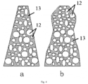
- each cemented stalagmite 11 of which an outer contour shape is a frustum-like shape or a gourd-like shape in the vertical direction is shown in Fig. 4 , wherein a is a sectional view of the frustum-like shape in the vertical direction, and b is a sectional view of the gourd-like shape in the vertical direction.
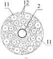
- the gridded distribution of the cemented stalagmites 11 is arranged in at least two annular areas with the building structure 2 as a center; and a plurality of the cemented stalagmites 11 are distributed in each annular area, as shown in Figs. 1 and 2 .
- the number of the annular areas in the gridded distribution is preferably 2-5, more preferably 2-3, for example, the cemented stalagmites 11 are divided into an inner ring and an outer ring, or an inner ring, a middle ring and an outer ring according to the structural characteristics of the offshore building structure 2.
- the number of the annular areas in the gridded cemented riprap scour-protection structure is set to be three, which are an inner ring, a middle ring and an outer ring from inside to outside, as shown in Fig. 1 .
- cemented stalagmites 11 arranged in two adjacent annular areas are staggered or continuously aligned, as shown in Fig. 2
- a is a schematic diagram of a continuous alignment of cemented stalagmites 11 arranged in two adjacent annular areas
- b is a schematic diagram of a staggered arrangement of cemented stalagmites 11 arranged in two adjacent annular areas.
- the structural strength of the cemented stalagmites 11 in the inner ring needs to be higher than that of the outer side, and the number also needs to be more than that of the outer side.
- the cemented stalagmites in the inner ring are closer to the building structure 2, and directly bear the sea current scouring effect caused by the building structure 2.
- the distance between cemented stalagmites 11 in an annular area closer to the building structure 2 is less than or equal to the distance between cemented stalagmites 11 in an annular area farther away from the building structure 2, as shown in Fig. 1 .
- the present invention also optimizes a filling ratio of the gelling substance 13 at each position in the vertical direction of the cemented stalagmites 11; in the gridded cemented riprap scour-protection structure, when the outer contour of each of the cemented stalagmites 11 has a frustum-like structure, preferably, a filling ratio of the gelling substance 13 at the top of each of the cemented stalagmites 11 is 5-30%, a filling ratio of the gelling substance 13 at the bottom of each of the cemented stalagmites 11 is 60-100%, and a filling ratio of the gelling substance 13 at the middle part of each of the cemented stalagmites 11 is 30-60%; and when the outer contour of each of the cemented stalagmites 11 has a gourd-like structure, the porosity of each of the cemented stalagmites 11 gradually decreases and then increases and then decreases from top to bottom, that is, the porosity of the middle part of each cemented stalagmite 11
- the cemented stalagmites 11 are obtained after the underwater cementing material flows, adheres and coagulates in the riprap accumulation.
- the underwater cementing material first flows downward under the action of gravity, and then spreads laterally along the riprap gaps, therefore, when pouring points between adjacent cemented stalagmites 11 are far away, the middle upper parts of the formed cemented stalagmites 11 are not in direct contact, and when the single-point pouring amount is sufficient, the underwater cementing material will spread laterally at the interface between cemented riprap and the foundation, and the distance between the lower or bottom parts of adjacent cemented stalagmites 11 is smaller or even connected.
- the middle upper parts of the cemented stalagmites 11 are not in direct contact with the adjacent cemented stalagmites 11, and the lower or bottom parts of the cemented stalagmites 11 are connected with the adjacent cemented stalagmites 11, which can effectively protect foundation soil under the grid cemented riprap scour-protection structure from being scoured.
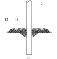
- the gridded cemented riprap scour-protection structure of the present invention can be applied to different offshore building structures, particularly as shown in Figs. 5-7 .
- the particle size of the riprap particles 12 in the present invention may be selected to be 50-500 mm
- the underwater cementing material may be commercially available underwater self-compacting early-strength concrete (e.g. early-strength retarding self-compacting concrete from Beijing Huashi Nagu Technology Co., Ltd.), underwater self-compacting early-strength mortar (e.g. early-strength retarding self-compacting mortar from Beijing Huashi Nagu Technology Co., Ltd.) or underwater self-compacting early-strength paste (e.g.
- the underwater cementing material may be homemade, for example, the self-compacting early-strength mortar is directly prepared by a conventional cement mortar preparation process by using 42.5 ordinary Portland cement, medium sand of a concrete mixing plant, stone with a particle size of 5-20 mm, a special admixture for underwater super early-strength self-protecting concrete produced by Beijing Huashi Nagu Company, a underwater protective agent produced by Beijing Huashi Nagu Company, and other materials such as water and a retarder. Whether purchased or homemade, it is only necessary to ensure that the strength of the cemented stalagmites is not less than IMPa after 6h of pouring.
- the slump flow of the underwater self-compacting early-strength concrete is 600-800mm
- the slump flow of the underwater self-compacting early-strength mortar and the underwater self-compacting early-strength paste is 260-320mm
- the plasticity retention time of the underwater cementing material is 30-120min.
- the scour-protection effect of the gridded cemented riprap scour-protection structure offshore is studied by a large-scale wave flume test based on a certain offshore wind farm in Jiangsu, wherein the pile diameter prototype value is 6.5 m, the particle size of the riprap is 150-350 mm, the height of the riprap accumulation is 1m, a protection radius is 15m, and topsoil is silt.
- the structure and the particle size of surrounding riprap are proportionally reduced, specifically, in the model, the pile diameter is 0.5 m, the particle size of the riprap is 11.5-23 mm, the height of the riprap accumulation is 0.04 m, a protection radius is 0.75 m, topsoil is silt, the gridded cemented riprap scour-protection structure is formed by pouring underwater self-compacting early-strength mortar, and the single-point pouring amount is 5L, wherein the slump flow of the mortar is 320 ⁇ 10 mm, the plasticity retention time is 30 min, the onshore strength and underwater strength of a mortar specimen in 6h are 3 MPa and 1.2 MPa, respectively, and the underwater strength of a cemented stalagmite specimen in 6h is 1.8 MPa.
- the test simulates a once-in-50-year extreme condition with a wave height of 9.01m, a period of 10.3s and a flow rate of 1.34m/s and a once-in-a-century extreme condition with a wave height of 11.44m, a period of 13.4s and a flow rate of 1.34m/s, and the maximum scouring depth is reduced from 4.42 m to 0.72 m under the once-in-50-year extreme condition, and the maximum scouring depth is reduced from 6.5 m to 1.16 m under the once-in-a-century extreme condition after the gridded cemented riprap scour-protection structure of the present invention is adopted for protection.
- the thickness and protection radius of the riprap accumulation in the gridded cemented riprap scour-protection structure are only half of the original size parameters, that is, the use amount of riprap is only 25.6% of the original use amount, which greatly saves the use amount of riprap particle raw materials.
Landscapes
- Engineering & Computer Science (AREA)
- General Engineering & Computer Science (AREA)
- Life Sciences & Earth Sciences (AREA)
- Civil Engineering (AREA)
- Structural Engineering (AREA)
- General Life Sciences & Earth Sciences (AREA)
- Paleontology (AREA)
- Mining & Mineral Resources (AREA)
- Mechanical Engineering (AREA)
- Environmental & Geological Engineering (AREA)
- Sustainable Development (AREA)
- Sustainable Energy (AREA)
- Chemical & Material Sciences (AREA)
- Combustion & Propulsion (AREA)
- Hydrology & Water Resources (AREA)
- Ocean & Marine Engineering (AREA)
- Revetment (AREA)
Abstract
Description
- The present invention relates to the technical field of marine engineering infrastructure scour-protection, in particular to a gridded cemented riprap scour-protection structure.
- The ocean has abundant resources and is an important area for future development. Offshore wind power has the advantage of being clean and efficient and is an important part of new energy. An infrastructure of the offshore wind power is an important support structure for the development and utilization of wind energy resources, and is also an extremely important offshore building structure. The layout of offshore building structures will change a sea current field, resulting in the formation of local scour pits around the building structures, which in turn affects the bearing capacity of the offshore building structures, and seriously threatens the safety of operation of structures such as upper fans and the stability of the overall structure.
- At present, offshore building structures such as offshore wind power pile foundations and cylindrical foundations usually adopt protective measures such as riprap, sand quilt, solidified soil, and bionic aquatic plants. According to the monitoring results of the Jiangsu sea area in China, the existing protective measures are poor in scour-protection effect. Especially when the riprap protective measures are adopted, riprap around the offshore building structures will be washed away by a water flow, forming scour pits with a depth of being up to 8m around the foundations.
- Therefore, there is an urgent need to propose a novel scour-protection structure for offshore building structures that is more excellent in scour-protection effect.
- Therefore, the technical problem to be solved by the present invention is to overcome the defect of a poor scour-protection effect of the existing protective measures, thereby providing a gridded cemented riprap scour-protection structure with a stronger scour-protection ability formed at the peripheries of offshore building structures; and the scour-protection structure can also reduce the thickness and range of riprap around the offshore building structures, thereby reducing the comprehensive cost of anti-scouring protection.
- A gridded cemented riprap scour-protection structure, including:
- riprap particles, uniformly distributed around the periphery of a building structure; and
- a gelling substance, filled between the riprap particles for connecting some of the riprap particles into a whole from top to bottom to form cemented stalagmites; wherein
- a plurality of the cemented stalagmites are formed around the building structure in a gridded distribution, and each cemented stalagmite has a structure with a smaller top and a larger bottom, and the riprap particles are at the peripheries of the cemented stalagmites.
- Each cemented stalagmite is of a frustum-like shape in which a porosity thereof gradually decreases from top to bottom, or a gourd-like shape in which a porosity thereof gradually decreases and then increases and then decreases from top to bottom.
- The above porosity in the present invention refers to the percentage of the volume of the corresponding pores in unit riprap particle accumulation to the total volume of the unit riprap particle accumulation.
- The gridded distribution of the cemented stalagmites is arranged in at least two annular areas with the building structure as a center; and a plurality of the cemented stalagmites are distributed in each annular area.
- The number of the annular areas in the gridded distribution is 2-5, and cemented stalagmites arranged in two adjacent annular areas are staggered or continuously aligned.
- The distance between cemented stalagmites in an annular area closer to the building structure is less than or equal to the distance between cemented stalagmites in an annular area farther away from the building structure.
- A filling ratio of the gelling substance at the top of each of the cemented stalagmites is 5-30%, and a filling ratio of the gelling substance at the bottom of each of the cemented stalagmites is 60-100%.
- A filling ratio at the middle part of each of the cemented stalagmites is 30-60%.
- The above filling ratio refers to the percentage of the volume occupied by the corresponding gelling substance in unit rubble particle accumulation to the total volume of the pores before the gelling substance is filled in the unit rubble particle accumulation.
- The riprap particles have a particle size of 50-500mm.
- The gelling substance is formed after an underwater cementing material flows, adheres and coagulates along the gaps between the riprap particles under the action of self-gravity.
- The underwater cementing material is self-compacting early-strength concrete, underwater self-compacting early-strength mortar or underwater self-compacting early-strength paste, and the fluidity and strength characteristics of the underwater cementing material are early-strength and retarding.
- The technical solution of the present invention has the following advantages:
- 1. the gridded cemented riprap scour-protection structure provided by the present invention is composed of the cemented stalagmites and the riprap particles surrounding the cemented stalagmites, wherein the cemented stalagmites, as a core structure, play a rigid skeleton support role, effectively resisting the scouring of a wave water flow, and ensuring the stability of the surrounding riprap particles; as an auxiliary structure, the riprap particles play the role of flexible muscle tissue and can adapt to their own structural deformation and foundation deformation; and the cemented stalagmites allow the surrounding riprap particles to move in a small range, but limit the movement in a large range, which ensures the continuity and transition of the stiffness of the gridded cemented riprap scour-protection structure and foundation soil, avoids the scouring of the peripheral foundation soil by the gridded cemented riprap scour-protection structure caused by a large difference in stiffness between the two, and achieves the purpose of improving the scour-protection ability.
- 2. The scour-protection structure provided by the present invention can make full use of the simplicity and maturity of the riprapping technology and the existing construction ships, and realize gridded cemented riprapping through a self-flow and controllable pouring process of the underwater cementing material. The protective structure with a stronger scour-protection ability is formed at the peripheries of the offshore building structures, and can improve the scour-protection ability of the original riprap accumulation, thereby reducing the thickness and range of riprap around the offshore building structures, reducing the use amount of riprap, thereby reducing the comprehensive cost of anti-scouring protection; and according to the results of a large-scale wave flume scour test carried out by the inventor, compared with a traditional riprap protection method, the gridded cemented riprap scour-protection structure reduces the thickness and accumulation range of riprap accumulation by 50% or more, respectively, and reduces the depth and range of the scour pits by 80%-95%.
- 3. The present invention can effectively change the scour-protection characteristics by controlling the internal structural features of the gridded cemented riprap scour-protection structure, such as the gridded arrangement of the cemented stalagmites, the filling ratio of the gelling substance, and the porosity of the cemented stalagmites, thereby improving the applicability to different sea areas and expanding the applicability range.
- 4. The gridded cemented riprap scour-protection structure of the present invention effectively breaks through the limitations of the existing riprap particle size of 100-350 mm and the riprap quality, facilitates selection of riprap materials on site, even with waste building material, slag and tailing enrockment, which effectively expands the source of raw materials, greatly facilitates the construction, and reduces the construction cost.
- In order to more clearly explain the specific embodiments of the present invention or the technical solution in the prior art, the drawings that need to be used in the description of the specific embodiments or the prior art will be briefly introduced below. Obviously, the drawings in the following description are some embodiments of the present invention. For those of ordinary skill in the art, other drawings can also be obtained based on these drawings without creative labor.
-
Fig. 1 is a top view of a gridded cemented riprap scour-protection structure according to the present invention; -
Fig. 2 is a structural schematic diagram of a gridded distribution of cemented stalagmites according to the present invention; -
Fig. 3 is a structural schematic diagram of a three-dimensional spatial arrangement of cemented stalagmites according to the present invention; -
Fig. 4 is a schematic diagram of a cross-sectional structure of cemented stalagmites with different outer contours in the vertical direction according to the present invention; -
Fig. 5 is a schematic diagram of a gridded cemented riprap scour-protection structure disposed on a first offshore building structure; -
Fig. 6 is a schematic diagram of a gridded cemented riprap scour-protection structure disposed on a second offshore building structure; and -
Fig. 7 is a schematic diagram of a gridded cemented riprap scour-protection structure disposed on a third offshore building structure. -
- 2-building structure; and
- 11-cemented stalagmite, 12-riprap particle, 13-gelling substance.
- The technical solutions of the present invention will be clearly and completely described below with reference to the accompanying drawings. Obviously, the described embodiments are a part of the embodiments of the present invention, but not all of the embodiments. Based on the embodiments of the present invention, all other embodiments obtained by those of ordinary skill in the art without creative labor all fall within the protection scope of the present invention.
- In the description of the present invention, it should be noted that, the terms "center", "upper", "lower", "vertical", "horizontal", "inside", "outside", and the like indicate an orientation or position relationship based on the orientation or position relationship shown in the drawings, which is only for the convenience of describing the present invention and simplifying the present description, rather than indicating or implying that the device or element referred to must have a specific orientation, be constructed and operated in a specific orientation, and therefore cannot be understood as a limitation of the present invention. In addition, the terms "first", "second", and "third" are used for descriptive purposes only and should not be construed as indicating or implying relative importance.
- In the description of the present invention, it should be noted that, unless otherwise expressly specified and defined, the terms "connected" and "connection" should be understood in a broad sense, for example, it may be a fixed connection, a detachable connection, or an integral connection; it may be a mechanical connection; it may be a direct connection, it can also be indirect connection through an intermediate medium, and it can be an internal communication of two components. For those of ordinary skill in the art, the specific meanings of the above terms in the present invention can be understood in specific situations.
- In addition, the technical features involved in different embodiments of the present invention described below can be combined with each other as long as they do not conflict with each other.
- A gridded cemented riprap scour-protection structure, as shown in
Figs. 1-3 , includes:riprap particles 12, uniformly distributed around the periphery of abuilding structure 2; and agelling substance 13 filled between theriprap particles 12 for connecting some of theriprap particles 12 into a whole from top to bottom to form cementedstalagmites 11; wherein a plurality of the cementedstalagmites 11 are formed around thebuilding structure 2 in a gridded distribution, and eachcemented stalagmite 11 has a structure with a smaller top and a larger bottom, and the peripheries of the cementedstalagmites 11 are surrounded by theriprap particles 12. - The gridded cemented riprap scour-protection structure provided by the present invention is composed of the cemented
stalagmites 11 and theriprap particles 12 surrounding the cementedstalagmites 11, wherein the cementedstalagmites 11, as a core structure, play a rigid skeleton support role, effectively resisting the scouring of a wave water flow, and ensuring the stability of the surroundingriprap particles 12; as an auxiliary structure, theriprap particles 12 play the role of flexible muscle tissue and can adapt to their own structural deformation and foundation deformation; and thecemented stalagmites 11 allow the surroundingriprap particles 12 to move in a small range, but limit the movement in a large range, which ensures the continuity and transition of the stiffness of the gridded cemented riprap scour-protection structure and foundation soil, avoids the scouring of the peripheral foundation soil by the gridded cemented riprap scour-protection structure caused by a large difference in stiffness between the two, and achieves the purpose of improving the scour-protection ability. - In the present invention, according to the specific spatial structure of the
cemented stalagmites 11 and the expected protective effect, the periphery of thebuilding structure 2 can be divided into a plurality of grid units, and each grid unit has thecemented stalagmites 11 of different structures and theriprap particles 12 that are distributed between the cementedstalagmites 11; and through the differentiated setting of the grid cells, the refined structure design is realized, and the economy and efficiency ratio are improved. - Wherein each cemented
stalagmite 11 is of an integrated structure formed by filling theriprap particles 12 with the gellingsubstance 13 to fix twoadjacent riprap particles 12; and it can be understood that the gellingsubstance 13 is formed after a cementing material is solidified. The cementedstalagmites 11 can be realized in a variety of ways, which can be formed by mixing the cementing material with theriprap particles 12 in a specific ratio to form a specific shape, and solidifying; and can also be formed by pouring an underwater cementing material, wherein the gaps between a plurality of theriprap particles 12 in the vertical direction are filled under the action of self-gravity of the underwater cementing material, and solidifing is performed to form integrated cementedstalagmites 11. - The cemented
stalagmites 11 in this embodiment are formed by pouring the underwater cementing material. Specifically, the underwater cementing material first flows downward under the action of gravity, and then diffuses laterally, thus forming a frustum-like shape in which a porosity thereof gradually decreases from top to bottom; and when the underwater cementing material is poured in multiple times, the previous pouring process changes the original gap structure of riprap accumulation, causing more underwater cementing materials to fill upper gaps and spread laterally, thus finally forming a gourd-like structure in which a porosity thereof gradually decreases and then increases and then decreases from top to bottom. Wherein a cross section of each cementedstalagmite 11 of which an outer contour shape is a frustum-like shape or a gourd-like shape in the vertical direction is shown inFig. 4 , wherein a is a sectional view of the frustum-like shape in the vertical direction, and b is a sectional view of the gourd-like shape in the vertical direction. - Wherein the gridded distribution of the cemented
stalagmites 11 is arranged in at least two annular areas with thebuilding structure 2 as a center; and a plurality of the cementedstalagmites 11 are distributed in each annular area, as shown inFigs. 1 and2 . The number of the annular areas in the gridded distribution is preferably 2-5, more preferably 2-3, for example, the cementedstalagmites 11 are divided into an inner ring and an outer ring, or an inner ring, a middle ring and an outer ring according to the structural characteristics of theoffshore building structure 2. - Specifically, in this embodiment, according to the spatial structure and size, the number of the annular areas in the gridded cemented riprap scour-protection structure is set to be three, which are an inner ring, a middle ring and an outer ring from inside to outside, as shown in
Fig. 1 . In this arrangement, cementedstalagmites 11 arranged in two adjacent annular areas are staggered or continuously aligned, as shown inFig. 2 , and inFig. 2 , a is a schematic diagram of a continuous alignment of cementedstalagmites 11 arranged in two adjacent annular areas, and b is a schematic diagram of a staggered arrangement of cementedstalagmites 11 arranged in two adjacent annular areas. - In general, the structural strength of the cemented
stalagmites 11 in the inner ring needs to be higher than that of the outer side, and the number also needs to be more than that of the outer side. This is because the cemented stalagmites in the inner ring are closer to thebuilding structure 2, and directly bear the sea current scouring effect caused by thebuilding structure 2. For this reason, in this embodiment, the distance between cementedstalagmites 11 in an annular area closer to thebuilding structure 2 is less than or equal to the distance between cementedstalagmites 11 in an annular area farther away from thebuilding structure 2, as shown inFig. 1 . - At the same time, the present invention also optimizes a filling ratio of the gelling
substance 13 at each position in the vertical direction of the cementedstalagmites 11; in the gridded cemented riprap scour-protection structure, when the outer contour of each of the cementedstalagmites 11 has a frustum-like structure, preferably, a filling ratio of the gellingsubstance 13 at the top of each of the cementedstalagmites 11 is 5-30%, a filling ratio of the gellingsubstance 13 at the bottom of each of the cementedstalagmites 11 is 60-100%, and a filling ratio of the gellingsubstance 13 at the middle part of each of the cementedstalagmites 11 is 30-60%; and when the outer contour of each of the cementedstalagmites 11 has a gourd-like structure, the porosity of each of the cementedstalagmites 11 gradually decreases and then increases and then decreases from top to bottom, that is, the porosity of the middle part of each cementedstalagmite 11 is higher than the porosity of the upper part and the porosity of the lower part, or the filling ratio of the upper part and the filling ratio of the lower part of each cementedstalagmite 11 are higher than that of the middle part, as shown inFig. 3 andFigs. 5-7 . - Specifically, in this embodiment, the cemented
stalagmites 11 are obtained after the underwater cementing material flows, adheres and coagulates in the riprap accumulation. The underwater cementing material first flows downward under the action of gravity, and then spreads laterally along the riprap gaps, therefore, when pouring points between adjacent cementedstalagmites 11 are far away, the middle upper parts of the formed cementedstalagmites 11 are not in direct contact, and when the single-point pouring amount is sufficient, the underwater cementing material will spread laterally at the interface between cemented riprap and the foundation, and the distance between the lower or bottom parts of adjacent cementedstalagmites 11 is smaller or even connected. That is, in the present invention, the middle upper parts of the cementedstalagmites 11 are not in direct contact with the adjacent cementedstalagmites 11, and the lower or bottom parts of the cementedstalagmites 11 are connected with the adjacent cementedstalagmites 11, which can effectively protect foundation soil under the grid cemented riprap scour-protection structure from being scoured. - The gridded cemented riprap scour-protection structure of the present invention can be applied to different offshore building structures, particularly as shown in
Figs. 5-7 . At the same time, the particle size of theriprap particles 12 in the present invention may be selected to be 50-500 mm, and the underwater cementing material may be commercially available underwater self-compacting early-strength concrete (e.g. early-strength retarding self-compacting concrete from Beijing Huashi Nagu Technology Co., Ltd.), underwater self-compacting early-strength mortar (e.g. early-strength retarding self-compacting mortar from Beijing Huashi Nagu Technology Co., Ltd.) or underwater self-compacting early-strength paste (e.g. early-strength retarding paste from Beijing Huashi Nagu Technology Co., Ltd.). At the same time, the underwater cementing material may be homemade, for example, the self-compacting early-strength mortar is directly prepared by a conventional cement mortar preparation process by using 42.5 ordinary Portland cement, medium sand of a concrete mixing plant, stone with a particle size of 5-20 mm, a special admixture for underwater super early-strength self-protecting concrete produced by Beijing Huashi Nagu Company, a underwater protective agent produced by Beijing Huashi Nagu Company, and other materials such as water and a retarder. Whether purchased or homemade, it is only necessary to ensure that the strength of the cemented stalagmites is not less than IMPa after 6h of pouring. In order to meet the pouring requirement of the underwater cementing material, the slump flow of the underwater self-compacting early-strength concrete is 600-800mm, the slump flow of the underwater self-compacting early-strength mortar and the underwater self-compacting early-strength paste is 260-320mm, and the plasticity retention time of the underwater cementing material is 30-120min. - The scour-protection effect of the gridded cemented riprap scour-protection structure offshore is studied by a large-scale wave flume test based on a certain offshore wind farm in Jiangsu, wherein the pile diameter prototype value is 6.5 m, the particle size of the riprap is 150-350 mm, the height of the riprap accumulation is 1m, a protection radius is 15m, and topsoil is silt.
- In a model test, the structure and the particle size of surrounding riprap are proportionally reduced, specifically, in the model, the pile diameter is 0.5 m, the particle size of the riprap is 11.5-23 mm, the height of the riprap accumulation is 0.04 m, a protection radius is 0.75 m, topsoil is silt, the gridded cemented riprap scour-protection structure is formed by pouring underwater self-compacting early-strength mortar, and the single-point pouring amount is 5L, wherein the slump flow of the mortar is 320±10 mm, the plasticity retention time is 30 min, the onshore strength and underwater strength of a mortar specimen in 6h are 3 MPa and 1.2 MPa, respectively, and the underwater strength of a cemented stalagmite specimen in 6h is 1.8 MPa.
- The test simulates a once-in-50-year extreme condition with a wave height of 9.01m, a period of 10.3s and a flow rate of 1.34m/s and a once-in-a-century extreme condition with a wave height of 11.44m, a period of 13.4s and a flow rate of 1.34m/s, and the maximum scouring depth is reduced from 4.42 m to 0.72 m under the once-in-50-year extreme condition, and the maximum scouring depth is reduced from 6.5 m to 1.16 m under the once-in-a-century extreme condition after the gridded cemented riprap scour-protection structure of the present invention is adopted for protection.
- Moreover, compared with the original size parameters of the riprap accumulation, the thickness and protection radius of the riprap accumulation in the gridded cemented riprap scour-protection structure are only half of the original size parameters, that is, the use amount of riprap is only 25.6% of the original use amount, which greatly saves the use amount of riprap particle raw materials.
- Obviously, the above embodiment is only an example for clear description, and is not intended to limit the embodiments. For those of ordinary skill in the art, changes or modifications in other different forms can also be made on the basis of the above description. There is no need and cannot be exhaustive of all the embodiments here. And the obvious changes or modifications derived therefrom are still within the protection scope of the present invention.
Claims (10)
- A gridded cemented riprap scour-protection structure, characterized by comprising:riprap particles (12), uniformly distributed around the periphery of a building structure (2); anda gelling substance (13), partially filled into the interstitial space between the riprap particles (12) for connecting some of the riprap particles (12) into a large aggregate cluster from top to bottom to form cemented stalagmites (11); whereina plurality of the cemented stalagmites (11) are formed around the building structure (2) in a grid pattern, and each cemented stalagmite (11) has a structure with a smaller top and a larger bottom.
- The gridded cemented riprap scour-protection structure according to claim 1, characterized in that each cemented stalagmite (11) is of a frustum-like shape in which the porosity gradually decreases from top to bottom, or a gourd-like shape in which the porosity gradually decreases and then increases and then decreases from top to bottom.
- The gridded cemented riprap scour-protection structure according to claim 1 or 2, characterized in that the grid pattern of the cemented stalagmites (11) is arranged in at least two annular areas with the building structure (2) as a center; and a plurality of the cemented stalagmites (11) are distributed in each annular area.
- The gridded cemented riprap scour-protection structure according to claim 3, characterized in that the number of the annular areas in the grid pattern is 2-5, and cemented stalagmites (11) arranged in two adjacent annular areas are staggered or continuously aligned.
- The gridded cemented riprap scour-protection structure according to claim 3, characterized in that the distance between cemented stalagmites (11) in the annular area closer to the building structure (2) is less than or equal to the distance between cemented stalagmites (11) in the annular area which is farther away from the building structure (2).
- The gridded cemented riprap scour-protection structure according to any one of claims 1-5, characterized in that 5%-30% of the void space of riprap stones is filled with the gelling substance (13) at the top section the cemented stalagmites (11), and 60%-100% of the void space of riprap stones is filled with the gelling substance (13) at the bottom section of the cemented stalagmites (11).
- The gridded cemented riprap scour-protection structure according to claim 6, characterized in that 30%-60% of the void space of riprap stones is filled with the gelling substance (13) at the middle part of the cemented stalagmites (11).
- The gridded cemented riprap scour-protection structure according to any one of claims 1-7, characterized in that the size of riprap particles (12) is 50-500mm.
- The gridded cemented riprap scour-protection structure according to any one of claims 1-8, characterized in that the gelling substance (13) is formed by a self-protection underwater cementing material, which flows through the void space of riprap stones and then adheres to the stone surface, deposits and fills into the small void space under self-weight.
- The gridded cemented riprap scour-protection structure according to claim 9, characterized in that the underwater cementing materials are self-compacting early-strength concrete, underwater self-compacting early-strength mortar or underwater self-compacting early-strength paste.
Applications Claiming Priority (1)
| Application Number | Priority Date | Filing Date | Title |
|---|---|---|---|
| CN202210126149.9A CN114457857B (en) | 2022-02-10 | 2022-02-10 | Gridding glued riprap scour prevention structure |
Publications (2)
| Publication Number | Publication Date |
|---|---|
| EP4227465A1 true EP4227465A1 (en) | 2023-08-16 |
| EP4227465B1 EP4227465B1 (en) | 2025-12-24 |
Family
ID=81412754
Family Applications (1)
| Application Number | Title | Priority Date | Filing Date |
|---|---|---|---|
| EP22206946.0A Active EP4227465B1 (en) | 2022-02-10 | 2022-11-11 | Gridded cemented riprap scour-protection structure |
Country Status (2)
| Country | Link |
|---|---|
| EP (1) | EP4227465B1 (en) |
| CN (1) | CN114457857B (en) |
Cited By (3)
| Publication number | Priority date | Publication date | Assignee | Title |
|---|---|---|---|---|
| CN117536163A (en) * | 2023-10-24 | 2024-02-09 | 中国长江三峡集团有限公司 | Active and passive scouring protection structure of offshore structure and construction method |
| CN119933179A (en) * | 2025-01-17 | 2025-05-06 | 中国铁建港航局集团有限公司 | An anti-scouring structure for offshore wind power pile foundation and construction method thereof |
| CN120867243A (en) * | 2025-07-22 | 2025-10-31 | 中交上海航道局有限公司 | Foot protection structure combining turning character blocks and loose flint stones and visual underwater construction method |
Families Citing this family (5)
| Publication number | Priority date | Publication date | Assignee | Title |
|---|---|---|---|---|
| CA3266055A1 (en) * | 2022-08-28 | 2024-03-07 | Econcrete Tech Ltd | Systems and units for marine infrastructure foundation scour protection |
| CN115653015B (en) * | 2022-11-11 | 2025-09-30 | 东南大学 | A bridge scour protection structure based on natural stones and its construction method |
| CN116180794B (en) * | 2023-01-05 | 2024-10-29 | 中国长江三峡集团有限公司 | Anti-scouring composite structure of self-cementing granular body |
| CN116163334B (en) * | 2023-01-05 | 2024-11-08 | 中国长江三峡集团有限公司 | Offshore wind power structured cemented riprap scour prevention composite structure and construction method |
| CN118958384A (en) * | 2024-08-30 | 2024-11-15 | 中国长江三峡集团有限公司 | A cross-particle size grading riprap anti-scour structure and construction method |
Citations (3)
| Publication number | Priority date | Publication date | Assignee | Title |
|---|---|---|---|---|
| EP0753628A1 (en) * | 1995-07-08 | 1997-01-15 | Josef Möbius Bau-Gesellschaft (GmbH & Co.) | Method and device for the construction of a revetement of natural stones |
| CN209397587U (en) * | 2018-11-12 | 2019-09-17 | 交通运输部天津水运工程科学研究所 | A kind of single pile protection against erosion river bottom protection |
| CN112922019A (en) * | 2021-03-08 | 2021-06-08 | 中国长江三峡集团有限公司 | Single-pile foundation for reinforcing soft soil foundation by offshore wind power vibroflotation cemented pile and construction method |
Family Cites Families (8)
| Publication number | Priority date | Publication date | Assignee | Title |
|---|---|---|---|---|
| CN105908687B (en) * | 2016-04-13 | 2018-04-10 | 水利部交通运输部国家能源局南京水利科学研究院 | Marine structure wash preventing method |
| CN108517838A (en) * | 2018-06-08 | 2018-09-11 | 长江南京航道工程局 | A kind of throwing reason stone concrete facing structure and its construction method |
| CN110438857B (en) * | 2019-07-12 | 2023-12-05 | 中交一公局第四工程有限公司 | A kind of reinforced cage stalagmite pile and its construction technology in mountainous and hilly areas |
| CN110984213B (en) * | 2019-12-19 | 2024-08-09 | 中国长江三峡集团有限公司 | Marine wind power single pile-friction cone composite foundation and construction method thereof |
| CN211646445U (en) * | 2020-01-17 | 2020-10-09 | 上海公路桥梁(集团)有限公司 | Riprap layer pile |
| CN213773502U (en) * | 2020-09-14 | 2021-07-23 | 河海大学 | Foundation scouring protective layer of offshore wind turbine in continental shelf sea area |
| CN112575638B (en) * | 2020-12-11 | 2022-11-11 | 宁波华康陆鼎建设有限公司 | Roadbed reinforcing structure adopting steel reinforcement cage bamboo shoot piles and construction process of roadbed reinforcing structure |
| CN113982016A (en) * | 2021-10-20 | 2022-01-28 | 长江勘测规划设计研究有限责任公司 | Novel pile foundation anti-scouring protection structure and construction method thereof |
-
2022
- 2022-02-10 CN CN202210126149.9A patent/CN114457857B/en active Active
- 2022-11-11 EP EP22206946.0A patent/EP4227465B1/en active Active
Patent Citations (3)
| Publication number | Priority date | Publication date | Assignee | Title |
|---|---|---|---|---|
| EP0753628A1 (en) * | 1995-07-08 | 1997-01-15 | Josef Möbius Bau-Gesellschaft (GmbH & Co.) | Method and device for the construction of a revetement of natural stones |
| CN209397587U (en) * | 2018-11-12 | 2019-09-17 | 交通运输部天津水运工程科学研究所 | A kind of single pile protection against erosion river bottom protection |
| CN112922019A (en) * | 2021-03-08 | 2021-06-08 | 中国长江三峡集团有限公司 | Single-pile foundation for reinforcing soft soil foundation by offshore wind power vibroflotation cemented pile and construction method |
Cited By (3)
| Publication number | Priority date | Publication date | Assignee | Title |
|---|---|---|---|---|
| CN117536163A (en) * | 2023-10-24 | 2024-02-09 | 中国长江三峡集团有限公司 | Active and passive scouring protection structure of offshore structure and construction method |
| CN119933179A (en) * | 2025-01-17 | 2025-05-06 | 中国铁建港航局集团有限公司 | An anti-scouring structure for offshore wind power pile foundation and construction method thereof |
| CN120867243A (en) * | 2025-07-22 | 2025-10-31 | 中交上海航道局有限公司 | Foot protection structure combining turning character blocks and loose flint stones and visual underwater construction method |
Also Published As
| Publication number | Publication date |
|---|---|
| EP4227465B1 (en) | 2025-12-24 |
| CN114457857B (en) | 2023-05-16 |
| CN114457857A (en) | 2022-05-10 |
Similar Documents
| Publication | Publication Date | Title |
|---|---|---|
| EP4227465B1 (en) | Gridded cemented riprap scour-protection structure | |
| CN204040050U (en) | Mixed type offshore wind power foundation structure | |
| CN104099903B (en) | High-base asphalt concrete core dam | |
| CN109853311A (en) | A kind of marine plain area Construction of Soft Soil Subgrade technique and road structure | |
| CN116180794A (en) | A kind of anti-scouring composite structure of self-adhesive granular body | |
| GB2609841A (en) | Monopile foundation using cemented vibroflotation pile to reinforce soft soil foundation for use in offshore wind power generation, and construction method | |
| CN201506969U (en) | Large-diameter dike piles and dike or wharf structures | |
| CN102235008A (en) | Engineering pile deviation preventing structure of soft soil foundation and pretreatment method | |
| CN205501927U (en) | Active service is refuted bank revetment wall and is increased structure | |
| CN113026795A (en) | Water wind power tower consolidation rockfill column pier surrounding type foundation and construction method thereof | |
| CN215715073U (en) | Heightening mixed dam structure combined with built earth-rock dam | |
| CN114277856B (en) | Anti-scour construction method for single pile foundation based on mosaic underwater cemented rock-fill | |
| CN210013191U (en) | The connection structure of the thin anti-seepage wall of the dam abutment percussion drilling groove and the masonry dam body | |
| CN221372281U (en) | Silt solidified soil anti-scouring structure of offshore wind turbine foundation | |
| CN204849807U (en) | Fill novel wind -powered electricity generation pylon basis of building rubbish | |
| CN218405382U (en) | Prefabricated pile core structure of assembled wharf | |
| CN214657189U (en) | Single pile foundation for reinforcing soft soil foundation by offshore wind power vibroflotation cemented pile | |
| CN212358268U (en) | Compression-resistant stiff cement-soil pile body structure | |
| CN110241827A (en) | A kind of underwater concreting construction method | |
| CN205205848U (en) | Cavity gravity type marine wind power basis | |
| CN100590271C (en) | a vertical embankment | |
| CN204370463U (en) | Ultra-soft cob brick loose tool assists suspended deck structure | |
| CN117286860A (en) | A rapid gridded foundation treatment construction method under soft plastic geological conditions | |
| CN205399508U (en) | Consolidate open caisson foundation's structure under water | |
| CN206428711U (en) | A kind of prefabricated bed course for mud class weak fault |
Legal Events
| Date | Code | Title | Description |
|---|---|---|---|
| PUAI | Public reference made under article 153(3) epc to a published international application that has entered the european phase |
Free format text: ORIGINAL CODE: 0009012 |
|
| STAA | Information on the status of an ep patent application or granted ep patent |
Free format text: STATUS: REQUEST FOR EXAMINATION WAS MADE |
|
| 17P | Request for examination filed |
Effective date: 20221111 |
|
| AK | Designated contracting states |
Kind code of ref document: A1 Designated state(s): AL AT BE BG CH CY CZ DE DK EE ES FI FR GB GR HR HU IE IS IT LI LT LU LV MC ME MK MT NL NO PL PT RO RS SE SI SK SM TR |
|
| GRAP | Despatch of communication of intention to grant a patent |
Free format text: ORIGINAL CODE: EPIDOSNIGR1 |
|
| STAA | Information on the status of an ep patent application or granted ep patent |
Free format text: STATUS: GRANT OF PATENT IS INTENDED |
|
| INTG | Intention to grant announced |
Effective date: 20250909 |
|
| RIC1 | Information provided on ipc code assigned before grant |
Ipc: E02B 3/12 20060101AFI20250901BHEP Ipc: E02B 17/00 20060101ALI20250901BHEP |
|
| GRAS | Grant fee paid |
Free format text: ORIGINAL CODE: EPIDOSNIGR3 |
|
| GRAA | (expected) grant |
Free format text: ORIGINAL CODE: 0009210 |
|
| STAA | Information on the status of an ep patent application or granted ep patent |
Free format text: STATUS: THE PATENT HAS BEEN GRANTED |
|
| AK | Designated contracting states |
Kind code of ref document: B1 Designated state(s): AL AT BE BG CH CY CZ DE DK EE ES FI FR GB GR HR HU IE IS IT LI LT LU LV MC ME MK MT NL NO PL PT RO RS SE SI SK SM TR |
|
| REG | Reference to a national code |
Ref country code: CH Ref legal event code: F10 Free format text: ST27 STATUS EVENT CODE: U-0-0-F10-F00 (AS PROVIDED BY THE NATIONAL OFFICE) Effective date: 20251224 Ref country code: GB Ref legal event code: FG4D |
|
| REG | Reference to a national code |
Ref country code: DE Ref legal event code: R096 Ref document number: 602022027343 Country of ref document: DE |
|
| REG | Reference to a national code |
Ref country code: LT Ref legal event code: MG9D |
|
| PG25 | Lapsed in a contracting state [announced via postgrant information from national office to epo] |
Ref country code: NO Free format text: LAPSE BECAUSE OF FAILURE TO SUBMIT A TRANSLATION OF THE DESCRIPTION OR TO PAY THE FEE WITHIN THE PRESCRIBED TIME-LIMIT Effective date: 20260324 |
|
| PG25 | Lapsed in a contracting state [announced via postgrant information from national office to epo] |
Ref country code: HR Free format text: LAPSE BECAUSE OF FAILURE TO SUBMIT A TRANSLATION OF THE DESCRIPTION OR TO PAY THE FEE WITHIN THE PRESCRIBED TIME-LIMIT Effective date: 20251224 Ref country code: FI Free format text: LAPSE BECAUSE OF FAILURE TO SUBMIT A TRANSLATION OF THE DESCRIPTION OR TO PAY THE FEE WITHIN THE PRESCRIBED TIME-LIMIT Effective date: 20251224 |
|
| PG25 | Lapsed in a contracting state [announced via postgrant information from national office to epo] |
Ref country code: RS Free format text: LAPSE BECAUSE OF FAILURE TO SUBMIT A TRANSLATION OF THE DESCRIPTION OR TO PAY THE FEE WITHIN THE PRESCRIBED TIME-LIMIT Effective date: 20260324 |
|
| PG25 | Lapsed in a contracting state [announced via postgrant information from national office to epo] |
Ref country code: LV Free format text: LAPSE BECAUSE OF FAILURE TO SUBMIT A TRANSLATION OF THE DESCRIPTION OR TO PAY THE FEE WITHIN THE PRESCRIBED TIME-LIMIT Effective date: 20251224 |
|
| REG | Reference to a national code |
Ref country code: NL Ref legal event code: MP Effective date: 20251224 |
|
| PG25 | Lapsed in a contracting state [announced via postgrant information from national office to epo] |
Ref country code: BG Free format text: LAPSE BECAUSE OF FAILURE TO SUBMIT A TRANSLATION OF THE DESCRIPTION OR TO PAY THE FEE WITHIN THE PRESCRIBED TIME-LIMIT Effective date: 20251224 |
|
| REG | Reference to a national code |
Ref country code: AT Ref legal event code: MK05 Ref document number: 1870830 Country of ref document: AT Kind code of ref document: T Effective date: 20251224 |
|
| PG25 | Lapsed in a contracting state [announced via postgrant information from national office to epo] |
Ref country code: NL Free format text: LAPSE BECAUSE OF FAILURE TO SUBMIT A TRANSLATION OF THE DESCRIPTION OR TO PAY THE FEE WITHIN THE PRESCRIBED TIME-LIMIT Effective date: 20251224 |
|
| PG25 | Lapsed in a contracting state [announced via postgrant information from national office to epo] |
Ref country code: LT Free format text: LAPSE BECAUSE OF FAILURE TO SUBMIT A TRANSLATION OF THE DESCRIPTION OR TO PAY THE FEE WITHIN THE PRESCRIBED TIME-LIMIT Effective date: 20251224 |
|
| PG25 | Lapsed in a contracting state [announced via postgrant information from national office to epo] |
Ref country code: SM Free format text: LAPSE BECAUSE OF FAILURE TO SUBMIT A TRANSLATION OF THE DESCRIPTION OR TO PAY THE FEE WITHIN THE PRESCRIBED TIME-LIMIT Effective date: 20251224 |
|
| PG25 | Lapsed in a contracting state [announced via postgrant information from national office to epo] |
Ref country code: ES Free format text: LAPSE BECAUSE OF FAILURE TO SUBMIT A TRANSLATION OF THE DESCRIPTION OR TO PAY THE FEE WITHIN THE PRESCRIBED TIME-LIMIT Effective date: 20251224 |
|
| PG25 | Lapsed in a contracting state [announced via postgrant information from national office to epo] |
Ref country code: PL Free format text: LAPSE BECAUSE OF FAILURE TO SUBMIT A TRANSLATION OF THE DESCRIPTION OR TO PAY THE FEE WITHIN THE PRESCRIBED TIME-LIMIT Effective date: 20251224 |
|
| PG25 | Lapsed in a contracting state [announced via postgrant information from national office to epo] |
Ref country code: IT Free format text: LAPSE BECAUSE OF FAILURE TO SUBMIT A TRANSLATION OF THE DESCRIPTION OR TO PAY THE FEE WITHIN THE PRESCRIBED TIME-LIMIT Effective date: 20251224 |
|
| PG25 | Lapsed in a contracting state [announced via postgrant information from national office to epo] |
Ref country code: AT Free format text: LAPSE BECAUSE OF FAILURE TO SUBMIT A TRANSLATION OF THE DESCRIPTION OR TO PAY THE FEE WITHIN THE PRESCRIBED TIME-LIMIT Effective date: 20251224 |
|
| PG25 | Lapsed in a contracting state [announced via postgrant information from national office to epo] |
Ref country code: EE Free format text: LAPSE BECAUSE OF FAILURE TO SUBMIT A TRANSLATION OF THE DESCRIPTION OR TO PAY THE FEE WITHIN THE PRESCRIBED TIME-LIMIT Effective date: 20251224 |
|
| PG25 | Lapsed in a contracting state [announced via postgrant information from national office to epo] |
Ref country code: IS Free format text: LAPSE BECAUSE OF FAILURE TO SUBMIT A TRANSLATION OF THE DESCRIPTION OR TO PAY THE FEE WITHIN THE PRESCRIBED TIME-LIMIT Effective date: 20260424 Ref country code: PT Free format text: LAPSE BECAUSE OF FAILURE TO SUBMIT A TRANSLATION OF THE DESCRIPTION OR TO PAY THE FEE WITHIN THE PRESCRIBED TIME-LIMIT Effective date: 20260424 |
|
| PG25 | Lapsed in a contracting state [announced via postgrant information from national office to epo] |
Ref country code: CZ Free format text: LAPSE BECAUSE OF FAILURE TO SUBMIT A TRANSLATION OF THE DESCRIPTION OR TO PAY THE FEE WITHIN THE PRESCRIBED TIME-LIMIT Effective date: 20251224 |
|
| PG25 | Lapsed in a contracting state [announced via postgrant information from national office to epo] |
Ref country code: SK Free format text: LAPSE BECAUSE OF FAILURE TO SUBMIT A TRANSLATION OF THE DESCRIPTION OR TO PAY THE FEE WITHIN THE PRESCRIBED TIME-LIMIT Effective date: 20251224 |
|
| PG25 | Lapsed in a contracting state [announced via postgrant information from national office to epo] |
Ref country code: SE Free format text: LAPSE BECAUSE OF FAILURE TO SUBMIT A TRANSLATION OF THE DESCRIPTION OR TO PAY THE FEE WITHIN THE PRESCRIBED TIME-LIMIT Effective date: 20251224 |