EP4227462A1 - Grinding machine and grinding method for a rail track - Google Patents
Grinding machine and grinding method for a rail track Download PDFInfo
- Publication number
- EP4227462A1 EP4227462A1 EP22156807.4A EP22156807A EP4227462A1 EP 4227462 A1 EP4227462 A1 EP 4227462A1 EP 22156807 A EP22156807 A EP 22156807A EP 4227462 A1 EP4227462 A1 EP 4227462A1
- Authority
- EP
- European Patent Office
- Prior art keywords
- working body
- grinding
- grinding machine
- bar
- rail track
- Prior art date
- Legal status (The legal status is an assumption and is not a legal conclusion. Google has not performed a legal analysis and makes no representation as to the accuracy of the status listed.)
- Pending
Links
Images





Classifications
-
- E—FIXED CONSTRUCTIONS
- E01—CONSTRUCTION OF ROADS, RAILWAYS, OR BRIDGES
- E01B—PERMANENT WAY; PERMANENT-WAY TOOLS; MACHINES FOR MAKING RAILWAYS OF ALL KINDS
- E01B31/00—Working rails, sleepers, baseplates, or the like, in or on the line; Machines, tools, or auxiliary devices specially designed therefor
- E01B31/02—Working rail or other metal track components on the spot
- E01B31/12—Removing metal from rails, rail joints, or baseplates, e.g. for deburring welds, reconditioning worn rails
- E01B31/17—Removing metal from rails, rail joints, or baseplates, e.g. for deburring welds, reconditioning worn rails by grinding
Definitions
- the present invention relates to a grinding machine for a rail track and a grinding method for a rail track.
- the objective of the present invention is to provide a grinding machine and a grinding method to change the grinding feed without deforming the machine body and without deviating a guidance wheel out of the rail track and without being inconvenient to operate, to tilt the machine for grinding the whole railhead, and/or to reduce the machine weight.
- a first aspect of the present invention provides a grinding machine for a rail track, comprising: a bar arranged in parallel to the rail track, a working body attaching to the bar and movable relative to the bar, a grinding unit connected to the working body for grinding the rail track, a motor for supplying power to the grinding unit, and a position adjustment mechanism attached to the working body and to the bar for adjusting the position of the working body so that the working body is movable relative to the bar to change the feed of the grinding unit onto the rail track.
- a first rotation means including a first axis and disposed between the working body and the bar, wherein the first rotation means allows the working body to be pivotable around the first axis in the direction T and to be movable relative to the bar in the direction U when the position adjustment mechanism moves the working body.
- a second rotation means including a second axis and disposed between the position adjustment mechanism and the bar, wherein the second rotation means allows the position adjustment mechanism to be pivotable around the second axis in direction S when the position adjustment mechanism moves the working body.
- the working body includes a hole for accommodating the first axis of the first rotation means when the working body incurs the movement in the direction U relative to the first rotation means during the operation of the position adjustment mechanism.
- the hole of the working body is shaped to keep the distance between the first axis of the first rotation means and the second axis of the second rotation means constant during the movement of the working body.
- the position adjustment mechanism includes: a driving actuator for an operator to activate the position adjustment mechanism, an adjustment spindle for changing the distance between the driving actuator and the second axis of the second rotation means by rotating the driving actuator, and a bellow covering around the adjustment spindle to protect dust from entering the adjustment spindle.
- the working body includes an extending flange for connecting the working body to the position adjustment mechanism.
- the first rotation means and the second rotation means are axially rotatable around the bar in the direction W so that the working body is tiltable around the bar to allow the grinding unit to grind the railhead of the rail track.
- a ninth aspect of the present invention according to one of the first to eighth aspects, further comprising a handle fixed on the bar for an operator to hold onto.
- the handle further comprises a stick in parallel to the bar.
- the working body comprising a clip which engages the working body to the stick of the handle or disengages the working body from the stick of the handle.
- the grinding unit is a grinding stone, a grinding disc, or a grinding belt.
- the driving actuator is driven by an operator, an electric power source, or a hydraulic power source.
- the driving actuator is a handwheel.
- the position adjustment mechanism includes a locking means for controlling the driving actuator.
- a seventeenth aspect of the present invention provides a grinding method for a rail track, comprising: providing a grinding machine according to one of the first to sixteenth aspects, grinding the rail track using the grinding machine, and actuating the position adjustment mechanism for adjusting the position of the working body so that the working body is movable relative to the bar to change the feed of the grinding unit onto the rail track.
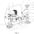
- Fig. 2 is a perspective view of a grinding machine for a rail track in accordance with the first embodiment of the present invention.
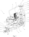
- Fig. 3 is another perspective view of the grinding machine of Fig. 2 .
- Fig. 4a is a front view of the grinding machine of Fig. 2 in the original position.
- Fig. 4b is an enlarged view of section A of the grinding machine of Fig. 4a in the original position.
- Fig. 5a is a front view of the grinding machine of Fig. 2 in the adjusted position.
- Fig. 5b is an enlarged view of section B of the grinding machine of Fig. 5a in the adjusted position.
- Fig. 6 is a front view of the grinding machine of Fig. 2 which is applied to a rail track in the original position.
- Fig. 4a is a front view of the grinding machine of Fig. 2 in the original position.
- Fig. 4b is an enlarged view of section A of the grinding machine of Fig. 4a in the original position.
- FIG. 7 is a front view of the grinding machine of Fig. 2 which is applied to a rail track in the adjusted position.
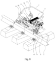
- Fig. 8 is a perspective view of the grinding machine of Fig. 2 which is applied to a rail track in the tilted position.
- Fig. 9 is a side view of the grinding machine of Fig. 2 which is applied to a rail track in the untilted position.
- Fig. 10 is a side view of the grinding machine of Fig. 2 which is applied to a rail track in the tilted position.
- a grinding machine 1 for a rail track 2 comprises: a bar 10, a working body 11, a grinding unit 12, a motor 13, a position adjustment mechanism 14, a first rotation means 15, a second rotation means 16, a handle 17, a front guidance wheel 18, and a back guidance wheel 19.
- the bar 10 is arranged in parallel to the rail track 2 and is equipped with the front guidance wheel 18 and the back guidance wheel 19 at the two ends of the bar 10.
- the front guidance wheel 18 and the back guidance wheel 19 guide the grinding machine 1 along the rail track 2 and avoid the grinding machine 1 falling out of the rail track 2.
- the working body 11 is attached to the bar 10 and is horizontally and axially movable relative to the bar 10.
- the working body 11 is used for holding the grinding unit 12 and the motor 13.
- the motor 13 can be provided outside of the grinding machine 1.
- the working body 11 includes an opening for accommodating the grinding unit 12.
- the grinding unit 12 is connected to the working body 11 for grinding and perpendicularly passes through the opening of the working body 11.
- the grinding unit 12 is a grinding stone.
- the grinding unit 12 can also be a grinding disc or a grinding belt.
- the grinding unit 12 can also be any kind of railway repairing tool, such as a driller unit, a preheater, a welder, or a clamp.
- the motor 13 is used for supplying power to the grinding unit 12.
- the power source of the motor 13 can be electrical power, batteries, gasoline source, diesel source, hydraulic source, or any kind of power source.
- the position adjustment mechanism 14 is attached to the working body 11 and is attached to the bar 10 for adjusting the position of the working body 11.
- the working body 11 is movable relative to the bar 10 to change the feed of the grinding unit 12 onto the rail track 2.
- the position adjustment mechanism 14 can change the grinding machine 1 from the original position ( Fig. 4a ) to the adjusted position ( Fig. 5a ).
- the working body 11 includes an extending flange 112 for connecting the working body 11 to the position adjustment mechanism 14. The extending flange 112 allows the operator to control the movement of the working body 11 easier.
- the handle 17 is fixed on the bar 10 for an operator to hold onto. During operation, the operator can hold the handle 17 to move the grinding machine 1 back and forth along the rail track 2 and tilt the grinding machine 1 around the railhead of the rail track 2.
- the grinding machine 1 includes a first rotation means 15 including a first axis 151 and a second rotation means 16 including a second axis 161 to change the grinding feed without deforming the grinding machine 1 and without deviating the front guidance wheel 18 and the back guidance wheel 19 out of the rail track 2.
- the first rotation means 15 includes the first axis 151 and is disposed between the working body 11 and the bar 10.
- the working body 11 includes a hole 111 for accommodating the first axis 151 of the first rotation means 15 when the working body 11 incurs a movement in the direction U relative to the first rotation means 15 during the operation of the position adjustment mechanism 14 so that the working body 11 is flexibly balanced.
- the hole 111 of the working body 11 is shaped to keep the distance between the first axis 151 of the first rotation means 15 and the second axis 161 of the second rotation means 16 constant during the movement of the working body 11.
- the hole 111 of the working body 11 facilitates the rotation of the working body 11 around the first axis 151 of the first rotation means 15.
- the front guidance wheel 18 and the back guidance wheel 19 do not deviate out of the rail track 2 because the distance therebetween keeps constant.
- the first axis 151 of the first rotation means 15 does not move along the direction U.
- the first rotation means 15 allows the working body 11 to be pivotable around the first axis 151 in the direction T and to be movable relative to the bar 10 in the direction U, as shown in Figs. 4b and 5b (the adjusted position).
- the second rotation means 16 includes the second axis 161 and is disposed between the position adjustment mechanism 14 and the bar 10.
- the second rotation means 16 allows the position adjustment mechanism 14 to be pivotable around the second axis 161 in direction S.
- the movement in the direction S at the second rotation means 16 and the movement in the direction U at the first rotation means 15 keep the length of the working body 11 balanced, as shown in Fig. 5a (the adjusted position). Namely, the working body 11 does not crush or deform from the movements when the grinding machine 1 changes from the original position ( Fig. 4a and 4b ) to the adjusted position ( Fig. 5a and 6b).
- the rotation mechanism of the first rotation means 15 and the second rotation means 16 leads to an angle ⁇ of at least 1.5 degrees between the working body 11 and the bar 10, as shown in Fig. 7 .
- the angle ⁇ can also be 0-20 degrees. Therefore, an angle between the grinding unit 12 and the rail track 2 may exist.
- the sloped grinding unit 12 also increases the grinding performance on the rail track 2, as shown in Fig. 7 .
- the position adjustment mechanism 14 includes a driving actuator 141, an adjustment spindle 142, a locking means 144, and a bellow 143.
- the position adjustment activates the movement in the direction R and changes the feed of the grinding unit 12.
- the driving actuator 141 is used for an operator to activate the position adjustment mechanism 14 by rotating or counter-rotating the wheel.
- the adjustment spindle 142 changes the distance between the driving actuator 141 and the second axis 161 of the second rotation means 16.
- the bellow 143 covering around the adjustment spindle 142 protects dust from entering the adjustment spindle 142.
- the bellow 143 is preferably made of rubber or plastic.
- the driving actuator 141 is driven by an operator and is a handwheel 1411.
- the operator can operate the handwheel 1411 by hand to control the adjustment spindle 142.
- the locking means 144 is used for controlling the rotation of the driving actuator 141 to prevent the driving actuator 141 from being automatically rotated. In other words, the locking means 144 prevents the driving actuator 141 from turning independently due to vibrations.
- the driving actuator 141 is driven by an electric power source or a hydraulic power source.
- the electric power source or the hydraulic power source can be installed on the handle 17 so that the operator can easily control the driving actuator 141 when the operator holds the handle 17. Namely, the operator does not need to turn the driving actuator 141 by hand. This helps the operator to easily use the grinding machine 1.
- the tilting function of the grinding machine 1 allows the operator to grind the whole railhead without hugely bending his or her body to operate the grinding machine 1. That is, the grinding machine 1 can be tilted from the untilted position ( Fig. 9 ) to the tilted position ( Fig. 10 ).
- the grinding machine 1 is convenient for an operator to grind the rail track 2.
- the first rotation means 15 and the second rotation means 16 are axially rotatable around the bar 10 in the direction W so that the working body 11 is tiltable around the bar 10 to allow the grinding unit 12 to grind the railhead of the rail track 2.
- the tiltable angle ⁇ of the working body 11 is from 0 to 90 degrees with respect to the handle 17.
- the tiltable angle ⁇ of the working body 11 can also be from 0 to 130 degrees in respect to the handle 17.
- the handle 17 further comprises a stick 171 parallel to the bar 10.
- the stick 171 is located nearly adjacent to the working body 11 and is parallel to the working body 11.
- the working body 11 comprises a clip 113.
- the operator When the operator grinds the top of the railhead, the operator can stand and does not need to bend his or her body to operate the grinding machine 1. At this time, the clip 113 engages the working body 11 to the stick 171 of the handle 17. In contrast, if the operator wants to grind the edge of the railhead, the operator just needs to disengage the working body 11 from the stick 171 of the handle 17. Namely, the clip 113 disengages the working body 11 from the stick 171 of the handle 17. In this way, the operator can tilt the working body 11 at a tilted position ( Fig. 8 ) for grinding the side of the rail track 2 (i.e., running edge).
- the present invention provides a grinding method for a rail track 2.
- the grinding machine 1 of the present invention is provided.
- the operator grinds the rail track 2 using the grinding machine 1.
- the operator can actuate the position adjustment mechanism 14 for adjusting the position of the working body 11 so that the working body 11 is movable relative to the bar 10 to change the feed of the grinding unit 12 onto the rail track 2. Namely, the grinding machine 1 is changed from the original position ( Fig. 6 ) to the adjusted position ( Fig. 7 ).
- the operator can disengage the clip 113 of the working body 11 from the stick 171 of the handle 17 so that the grinding machine 1 is changed from the untilted position ( Fig. 9 ) to the tilted position ( Fig. 10 ).
- the present invention can change the grinding feed efficiently without deforming the working body 11 and without deviating the front guidance wheel 18 and the back guidance wheel 19 out of the rail track 2, and can tilt the grinding machine 1 for grinding the whole railhead, and can reduce the grinding machine 1 weight.
Landscapes
- Engineering & Computer Science (AREA)
- Mechanical Engineering (AREA)
- Architecture (AREA)
- Civil Engineering (AREA)
- Structural Engineering (AREA)
- Machines For Laying And Maintaining Railways (AREA)
Abstract
The present invention relates to a grinding machine for a rail track, comprising: a bar (10) arranged in parallel to the rail track (2), a working body (11) attaching to the bar (10) and movable relative to the bar (10), a grinding unit (12) connected to the working body (11) for grinding the rail track (2), a motor (13) for supplying power to the grinding unit (12), and a position adjustment mechanism (14) attached to the working body (11) and to the bar (10) for adjusting the position of the working body (11) so that the working body (11) is movable relative to the bar (10) to change the feed of the grinding unit (12) onto the rail track (2).
Description
- The present invention relates to a grinding machine for a rail track and a grinding method for a rail track.
- Seamless rail track construction and maintenance require on-site welding of rails. To rework the weld joint and align the railhead contour, an operator needs to grind the top and the side of the rail track. In this way, the reworked rail track prevents traffic accidents.
- In 1977, Elektro-Thermit Essen published a grinding machine called "Elemka", as shown in
Fig. 1 . The grinding stone is fed to contact the rail track through a height adjustment mechanism. When the machine changes the grinding feed with the height adjustment mechanism at one side, the distance between two guidance wheels changes. In addition, the machine is designed only for grinding the running surface and is not suitable not for grinding the running edge of the rail track. The machine also leaves the weight of the machine on the operator. Patent No.WO2018215362A1 shows that an electrical mechanism vertically changes the position of the grinding stone, but such an electrical mechanism is more expensive and heavier. - The objective of the present invention is to provide a grinding machine and a grinding method to change the grinding feed without deforming the machine body and without deviating a guidance wheel out of the rail track and without being inconvenient to operate, to tilt the machine for grinding the whole railhead, and/or to reduce the machine weight.
- The following summarizes some aspects of the present invention to provide a basic understanding of the technology discussed. This summary is not an extensive overview of all contemplated features of the invention, and is intended neither to identify key or critical elements of all aspects of the invention nor to delineate the scope of any or all aspects of the invention. Its sole purpose is to present some concepts of one or more aspects of the invention in a summary form as a prelude to the more detailed description that is presented later.
- A first aspect of the present invention provides a grinding machine for a rail track, comprising: a bar arranged in parallel to the rail track, a working body attaching to the bar and movable relative to the bar, a grinding unit connected to the working body for grinding the rail track, a motor for supplying power to the grinding unit, and a position adjustment mechanism attached to the working body and to the bar for adjusting the position of the working body so that the working body is movable relative to the bar to change the feed of the grinding unit onto the rail track.
- In a second aspect of the present invention according to the first aspect, further comprising: a first rotation means including a first axis and disposed between the working body and the bar, wherein the first rotation means allows the working body to be pivotable around the first axis in the direction T and to be movable relative to the bar in the direction U when the position adjustment mechanism moves the working body.
- In a third aspect of the present invention according to the second aspect, further comprising: a second rotation means including a second axis and disposed between the position adjustment mechanism and the bar, wherein the second rotation means allows the position adjustment mechanism to be pivotable around the second axis in direction S when the position adjustment mechanism moves the working body.
- In a fourth aspect of the present invention according to the third aspect, the working body includes a hole for accommodating the first axis of the first rotation means when the working body incurs the movement in the direction U relative to the first rotation means during the operation of the position adjustment mechanism.
- In a fifth aspect of the present invention according to the fourth aspect, the hole of the working body is shaped to keep the distance between the first axis of the first rotation means and the second axis of the second rotation means constant during the movement of the working body.
- In a sixth aspect of the present invention according to one of the third to fifth aspects, the position adjustment mechanism includes: a driving actuator for an operator to activate the position adjustment mechanism, an adjustment spindle for changing the distance between the driving actuator and the second axis of the second rotation means by rotating the driving actuator, and a bellow covering around the adjustment spindle to protect dust from entering the adjustment spindle.
- In a seventh aspect of the present invention according to one of the first to sixth aspects, the working body includes an extending flange for connecting the working body to the position adjustment mechanism.
- In an eighth aspect of the present invention according to one of the third to fifth aspects, the first rotation means and the second rotation means are axially rotatable around the bar in the direction W so that the working body is tiltable around the bar to allow the grinding unit to grind the railhead of the rail track.
- In a ninth aspect of the present invention according to one of the first to eighth aspects, further comprising a handle fixed on the bar for an operator to hold onto.
- In a tenth aspect of the present invention according to the ninth aspect, the handle further comprises a stick in parallel to the bar.
- In an eleventh aspect of the present invention according to the tenth aspect, the working body comprising a clip which engages the working body to the stick of the handle or disengages the working body from the stick of the handle.
- In a twelfth aspect of the present invention according to one of the first to eleventh aspects, the grinding unit is a grinding stone, a grinding disc, or a grinding belt.
- In a thirteen aspect of the present invention according to one of the first to twelfth aspects, further comprising a front guidance wheel and a back guidance wheel for guiding the grinding machine along the rail track.
- In a fourteen aspect of the present invention according to the sixth aspect, the driving actuator is driven by an operator, an electric power source, or a hydraulic power source. In a fifteenth aspect of the present invention according to the fourteenth aspect, the driving actuator is a handwheel.
- In a sixteenth aspect of the present invention according to the fifteenth aspect, the position adjustment mechanism includes a locking means for controlling the driving actuator.
- A seventeenth aspect of the present invention provides a grinding method for a rail track, comprising: providing a grinding machine according to one of the first to sixteenth aspects, grinding the rail track using the grinding machine, and actuating the position adjustment mechanism for adjusting the position of the working body so that the working body is movable relative to the bar to change the feed of the grinding unit onto the rail track.
- Further benefits and advantages of the present invention will become apparent after a careful reading of the detailed description with appropriate reference to the accompanying drawings.
-
-
Fig. 1 is a perspective view of a conventional grinding machine. -
Fig. 2 is a perspective view of a grinding machine for a rail track in accordance with an embodiment of the present invention. -
Fig. 3 is another perspective view of the grinding machine ofFig. 2 . -
Fig. 4a is a front view of the grinding machine ofFig. 2 in the original position. -
Fig. 4b is an enlarged view of section A of the grinding machine ofFig. 4a in the original position. -
Fig. 5a is a front view of the grinding machine ofFig. 2 in the adjusted position. -
Fig. 5b is an enlarged view of section B of the grinding machine ofFig. 5a in the adjusted position. -
Fig. 6 is a front view of the grinding machine ofFig. 2 which is applied to a rail track in the original position. -
Fig. 7 is a front view of the grinding machine ofFig. 2 which is applied to a rail track in the adjusted position. -
Fig. 8 is a perspective view of the grinding machine ofFig. 2 which is applied to a rail track in the tilted position. -
Fig. 9 is a side view of the grinding machine ofFig. 2 which is applied to a rail track in the untilted position. -
Fig. 10 is a side view of the grinding machine ofFig. 2 which is applied to a rail track in the tilted position. - Although the invention has been explained in relation to its preferred embodiment(s) as mentioned above, it is to be understood that many other possible modifications and variations can be made without departing from the scope of the present invention. It is, therefore, contemplated that the appended claim or claims will cover such modifications and variations that fall within the true scope of the invention.
-
Fig. 2 is a perspective view of a grinding machine for a rail track in accordance with the first embodiment of the present invention.Fig. 3 is another perspective view of the grinding machine ofFig. 2 .Fig. 4a is a front view of the grinding machine ofFig. 2 in the original position.Fig. 4b is an enlarged view of section A of the grinding machine ofFig. 4a in the original position.Fig. 5a is a front view of the grinding machine ofFig. 2 in the adjusted position.Fig. 5b is an enlarged view of section B of the grinding machine ofFig. 5a in the adjusted position.Fig. 6 is a front view of the grinding machine ofFig. 2 which is applied to a rail track in the original position.Fig. 7 is a front view of the grinding machine ofFig. 2 which is applied to a rail track in the adjusted position.Fig. 8 is a perspective view of the grinding machine ofFig. 2 which is applied to a rail track in the tilted position.Fig. 9 is a side view of the grinding machine ofFig. 2 which is applied to a rail track in the untilted position.Fig. 10 is a side view of the grinding machine ofFig. 2 which is applied to a rail track in the tilted position. - In the following text, please refer to
Figs. 2-10 together. A grindingmachine 1 for arail track 2 comprises: abar 10, a workingbody 11, a grindingunit 12, amotor 13, aposition adjustment mechanism 14, a first rotation means 15, a second rotation means 16, ahandle 17, afront guidance wheel 18, and aback guidance wheel 19. Specifically, thebar 10 is arranged in parallel to therail track 2 and is equipped with thefront guidance wheel 18 and theback guidance wheel 19 at the two ends of thebar 10. Thefront guidance wheel 18 and theback guidance wheel 19 guide the grindingmachine 1 along therail track 2 and avoid the grindingmachine 1 falling out of therail track 2. - The working
body 11 is attached to thebar 10 and is horizontally and axially movable relative to thebar 10. The workingbody 11 is used for holding the grindingunit 12 and themotor 13. In a preferred embodiment, themotor 13 can be provided outside of the grindingmachine 1. The workingbody 11 includes an opening for accommodating the grindingunit 12. The grindingunit 12 is connected to the workingbody 11 for grinding and perpendicularly passes through the opening of the workingbody 11. The grindingunit 12 is a grinding stone. In other embodiments, the grindingunit 12 can also be a grinding disc or a grinding belt. In another embodiment, the grindingunit 12 can also be any kind of railway repairing tool, such as a driller unit, a preheater, a welder, or a clamp. - The
motor 13 is used for supplying power to the grindingunit 12. The power source of themotor 13 can be electrical power, batteries, gasoline source, diesel source, hydraulic source, or any kind of power source. - The
position adjustment mechanism 14 is attached to the workingbody 11 and is attached to thebar 10 for adjusting the position of the workingbody 11. Hence, the workingbody 11 is movable relative to thebar 10 to change the feed of the grindingunit 12 onto therail track 2. Namely, theposition adjustment mechanism 14 can change the grindingmachine 1 from the original position (Fig. 4a ) to the adjusted position (Fig. 5a ). In a preferred embodiment, the workingbody 11 includes an extendingflange 112 for connecting the workingbody 11 to theposition adjustment mechanism 14. The extendingflange 112 allows the operator to control the movement of the workingbody 11 easier. - The
handle 17 is fixed on thebar 10 for an operator to hold onto. During operation, the operator can hold thehandle 17 to move the grindingmachine 1 back and forth along therail track 2 and tilt the grindingmachine 1 around the railhead of therail track 2. - Please see
Figs, 4a ,4b ,5a , and5b . In a preferred embodiment, the grindingmachine 1 includes a first rotation means 15 including afirst axis 151 and a second rotation means 16 including asecond axis 161 to change the grinding feed without deforming the grindingmachine 1 and without deviating thefront guidance wheel 18 and theback guidance wheel 19 out of therail track 2. - The first rotation means 15 includes the
first axis 151 and is disposed between the workingbody 11 and thebar 10. The workingbody 11 includes ahole 111 for accommodating thefirst axis 151 of the first rotation means 15 when the workingbody 11 incurs a movement in the direction U relative to the first rotation means 15 during the operation of theposition adjustment mechanism 14 so that the workingbody 11 is flexibly balanced. Specifically, thehole 111 of the workingbody 11 is shaped to keep the distance between thefirst axis 151 of the first rotation means 15 and thesecond axis 161 of the second rotation means 16 constant during the movement of the workingbody 11. In addition, thehole 111 of the workingbody 11 facilitates the rotation of the workingbody 11 around thefirst axis 151 of the first rotation means 15. Thefront guidance wheel 18 and theback guidance wheel 19 do not deviate out of therail track 2 because the distance therebetween keeps constant. - The
first axis 151 of the first rotation means 15 does not move along the direction U. When theposition adjustment mechanism 14 moves the workingbody 11, the first rotation means 15 allows the workingbody 11 to be pivotable around thefirst axis 151 in the direction T and to be movable relative to thebar 10 in the direction U, as shown inFigs. 4b and5b (the adjusted position). - The second rotation means 16 includes the
second axis 161 and is disposed between theposition adjustment mechanism 14 and thebar 10. When theposition adjustment mechanism 14 moves the workingbody 11 and when theposition adjustment mechanism 14 moves down in the direction R, the second rotation means 16 allows theposition adjustment mechanism 14 to be pivotable around thesecond axis 161 in direction S. The movement in the direction S at the second rotation means 16 and the movement in the direction U at the first rotation means 15 keep the length of the workingbody 11 balanced, as shown inFig. 5a (the adjusted position). Namely, the workingbody 11 does not crush or deform from the movements when the grindingmachine 1 changes from the original position (Fig. 4a and4b ) to the adjusted position (Fig. 5a and 6b). - In a preferred embodiment, the rotation mechanism of the first rotation means 15 and the second rotation means 16 leads to an angle θ of at least 1.5 degrees between the working
body 11 and thebar 10, as shown inFig. 7 . The angle θ can also be 0-20 degrees. Therefore, an angle between the grindingunit 12 and therail track 2 may exist. The sloped grindingunit 12 also increases the grinding performance on therail track 2, as shown inFig. 7 . - Please refer to
Figs. 2-10 . Theposition adjustment mechanism 14 includes a drivingactuator 141, anadjustment spindle 142, a locking means 144, and abellow 143. The position adjustment activates the movement in the direction R and changes the feed of the grindingunit 12. Specifically, the drivingactuator 141 is used for an operator to activate theposition adjustment mechanism 14 by rotating or counter-rotating the wheel. By rotating the drivingactuator 141, theadjustment spindle 142 changes the distance between the drivingactuator 141 and thesecond axis 161 of the second rotation means 16. Thebellow 143 covering around theadjustment spindle 142 protects dust from entering theadjustment spindle 142. Thebellow 143 is preferably made of rubber or plastic. - In an embodiment, the driving
actuator 141 is driven by an operator and is ahandwheel 1411. The operator can operate thehandwheel 1411 by hand to control theadjustment spindle 142. The locking means 144 is used for controlling the rotation of the drivingactuator 141 to prevent the drivingactuator 141 from being automatically rotated. In other words, the locking means 144 prevents the drivingactuator 141 from turning independently due to vibrations. - In another preferred embodiment, the driving
actuator 141 is driven by an electric power source or a hydraulic power source. For example, the electric power source or the hydraulic power source can be installed on thehandle 17 so that the operator can easily control the drivingactuator 141 when the operator holds thehandle 17. Namely, the operator does not need to turn the drivingactuator 141 by hand. This helps the operator to easily use the grindingmachine 1. - The tilting function of the grinding
machine 1 allows the operator to grind the whole railhead without hugely bending his or her body to operate the grindingmachine 1. That is, the grindingmachine 1 can be tilted from the untilted position (Fig. 9 ) to the tilted position (Fig. 10 ). The grindingmachine 1 is convenient for an operator to grind therail track 2. As shown inFig. 6 , the first rotation means 15 and the second rotation means 16 are axially rotatable around thebar 10 in the direction W so that the workingbody 11 is tiltable around thebar 10 to allow the grindingunit 12 to grind the railhead of therail track 2. The tiltable angle Ω of the workingbody 11 is from 0 to 90 degrees with respect to thehandle 17. In a preferable embodiment, the tiltable angle Ω of the workingbody 11 can also be from 0 to 130 degrees in respect to thehandle 17. Thehandle 17 further comprises astick 171 parallel to thebar 10. Thestick 171 is located nearly adjacent to the workingbody 11 and is parallel to the workingbody 11. The workingbody 11 comprises aclip 113. - When the operator grinds the top of the railhead, the operator can stand and does not need to bend his or her body to operate the grinding
machine 1. At this time, theclip 113 engages the workingbody 11 to thestick 171 of thehandle 17. In contrast, if the operator wants to grind the edge of the railhead, the operator just needs to disengage the workingbody 11 from thestick 171 of thehandle 17. Namely, theclip 113 disengages the workingbody 11 from thestick 171 of thehandle 17. In this way, the operator can tilt the workingbody 11 at a tilted position (Fig. 8 ) for grinding the side of the rail track 2 (i.e., running edge). - The present invention provides a grinding method for a
rail track 2. When an operator wants to rework the weld joint and align the railhead contour, the grindingmachine 1 of the present invention is provided. The operator grinds therail track 2 using the grindingmachine 1. When the grindingunit 12 is getting worn out, the operator can actuate theposition adjustment mechanism 14 for adjusting the position of the workingbody 11 so that the workingbody 11 is movable relative to thebar 10 to change the feed of the grindingunit 12 onto therail track 2. Namely, the grindingmachine 1 is changed from the original position (Fig. 6 ) to the adjusted position (Fig. 7 ). When the operator wants to grind therail track 2 from the top of the rail track 2 (running surface) to the side of the rail track 2 (running edge), the operator can disengage theclip 113 of the workingbody 11 from thestick 171 of thehandle 17 so that the grindingmachine 1 is changed from the untilted position (Fig. 9 ) to the tilted position (Fig. 10 ). - To sum up, the present invention can change the grinding feed efficiently without deforming the working
body 11 and without deviating thefront guidance wheel 18 and theback guidance wheel 19 out of therail track 2, and can tilt the grindingmachine 1 for grinding the whole railhead, and can reduce the grindingmachine 1 weight. -
- 1
- grinding machine
- 10
- bar
- 11
- working body
- 111
- hole
- 112
- extending flange
- 113
- clip
- 12
- grinding unit
- 13
- motor
- 14
- position adjustment mechanism
- 141
- driving actuator
- 1411
- handwheel
- 142
- adjustment spindle
- 143
- bellow
- 144
- locking means
- 15
- first rotation means
- 151
- first axis
- 16
- second rotation means
- 161
- second axis
- 17
- handle
- 171
- stick
- 18
- front guidance wheel
- 19
- back guidance wheel
- 2
- rail track
- R, T, U, S, W
- direction
- θ, Ω
- angle
Claims (17)
- A grinding machine for a rail track, comprising:a bar (10) arranged in parallel to the rail track (2),a working body (11) attaching to the bar (10) and movable relative to the bar (10),a grinding unit (12) connected to the working body (11) for grinding the rail track (2),a motor (13) for supplying power to the grinding unit (12), anda position adjustment mechanism (14) attached to the working body (11) and to the bar (10) for adjusting the position of the working body (11) so that the working body (11) is movable relative to the bar (10) to change the feed of the grinding unit (12) onto the rail track (2).
- The grinding machine of Claim 1, further comprising:
a first rotation means (15) including a first axis (151) and disposed between the working body (11) and the bar (10), wherein the first rotation means (15) allows the working body (11) to be pivotable around the first axis (151) in the direction T and to be movable relative to the bar (10) in the direction U when the position adjustment mechanism (14) moves the working body (11). - The grinding machine of Claim 2, further comprising:
a second rotation means (16) including a second axis (161) and disposed between the position adjustment mechanism (14) and the bar (10), wherein the second rotation means (16) allows the position adjustment mechanism (14) to be pivotable around the second axis (161) in direction S when the position adjustment mechanism (14) moves the working body (11). - The grinding machine of Claim 3, wherein the working body (11) includes a hole (111) for accommodating the first axis (151) of the first rotation means (15) when the working body (11) incurs the movement in the direction U relative to the first rotation means (15) during the operation of the position adjustment mechanism (14).
- The grinding machine of Claim 4, wherein the hole (111) of the working body (11) is shaped to keep the distance between the first axis (151) of the first rotation means (15) and the second axis (161) of the second rotation means (16) constant during the movement of the working body (11).
- The grinding machine of one of Claim 3-5, wherein the position adjustment mechanism (14) includes:a driving actuator (141) for an operator to activate the position adjustment mechanism (14),an adjustment spindle (142) for changing the distance between the driving actuator (141) and the second axis (161) of the second rotation means (16) by rotating the driving actuator (141), anda bellow (143) covering around the adjustment spindle (142) to protect dust from entering the adjustment spindle (142).
- The grinding machine of one of Claim 1-6, wherein the working body (11) includes an extending flange (112) for connecting the working body (11) to the position adjustment mechanism (14).
- The grinding machine of one of Claims 3-5, wherein the first rotation means (15) and the second rotation means (16) are axially rotatable around the bar (10) in the direction W so that the working body (11) is tiltable around the bar (10) to allow the grinding unit (12) to grind the railhead of the rail track (2).
- The grinding machine of one of Claims 1-8, further comprising a handle (17) fixed on the bar (10) for an operator to hold onto.
- The grinding machine of Claim 9, wherein the handle (17) further comprises a stick (171) in parallel to the bar (10).
- The grinding machine of Claim 10, wherein the working body (11) comprising a clip (113) which engages the working body (11) to the stick (171) of the handle (17) or disengages the working body (11) from the stick (171) of the handle (17).
- The grinding machine of one of Claims 1-11, wherein the grinding unit (12) is a grinding stone, a grinding disc, or a grinding belt.
- The grinding machine of one of Claims 1-12, further comprising a front guidance wheel (18) and a back guidance wheel (19) for guiding the grinding machine (1) along the rail track (2).
- The grinding machine of Claim 6, wherein the driving actuator (141) is driven by an operator, an electric power source, or a hydraulic power source.
- The grinding machine of Claim 14, wherein the driving actuator (141) is a handwheel (1411).
- The grinding machine of Claim 15, wherein the position adjustment mechanism (14) includes a locking means (144) for controlling the driving actuator (141).
- A grinding method for a rail track, comprising:providing a grinding machine (1) according to one of Claims 1 to 16,grinding the rail track (2) using the grinding machine (1), andactuating the position adjustment mechanism (14) for adjusting the position of the working body (11) so that the working body (11) is movable relative to the bar (10) to change the feed of the grinding unit (12) onto the rail track (2).
Priority Applications (2)
| Application Number | Priority Date | Filing Date | Title |
|---|---|---|---|
| EP22156807.4A EP4227462A1 (en) | 2022-02-15 | 2022-02-15 | Grinding machine and grinding method for a rail track |
| PCT/EP2023/051982 WO2023156166A1 (en) | 2022-02-15 | 2023-01-27 | Grinding machine and grinding method for a rail track |
Applications Claiming Priority (1)
| Application Number | Priority Date | Filing Date | Title |
|---|---|---|---|
| EP22156807.4A EP4227462A1 (en) | 2022-02-15 | 2022-02-15 | Grinding machine and grinding method for a rail track |
Publications (1)
| Publication Number | Publication Date |
|---|---|
| EP4227462A1 true EP4227462A1 (en) | 2023-08-16 |
Family
ID=80682747
Family Applications (1)
| Application Number | Title | Priority Date | Filing Date |
|---|---|---|---|
| EP22156807.4A Pending EP4227462A1 (en) | 2022-02-15 | 2022-02-15 | Grinding machine and grinding method for a rail track |
Country Status (2)
| Country | Link |
|---|---|
| EP (1) | EP4227462A1 (en) |
| WO (1) | WO2023156166A1 (en) |
Citations (6)
| Publication number | Priority date | Publication date | Assignee | Title |
|---|---|---|---|---|
| US2118621A (en) * | 1935-02-15 | 1938-05-24 | Henry J Perazzoli | Track grinder |
| WO2012146540A1 (en) * | 2011-04-26 | 2012-11-01 | Fama S.R.L. | Tangential grinding machine |
| CN203144852U (en) * | 2013-01-29 | 2013-08-21 | 呼和浩特铁路局焊轨段 | Track circuit poor shunting grinding machine |
| WO2017035210A1 (en) * | 2015-08-24 | 2017-03-02 | Stanley Black & Decker, Inc. | Railroad track tool apparatus |
| DE202017002300U1 (en) * | 2017-04-29 | 2018-01-15 | Robel Bahnbaumaschinen Gmbh | Grinding machine for grinding a rail of a track |
| WO2018215362A1 (en) | 2017-05-26 | 2018-11-29 | Robel Bahnbaumaschinen Gmbh | Rail grinding machine, and grinding method |
-
2022
- 2022-02-15 EP EP22156807.4A patent/EP4227462A1/en active Pending
-
2023
- 2023-01-27 WO PCT/EP2023/051982 patent/WO2023156166A1/en not_active Ceased
Patent Citations (6)
| Publication number | Priority date | Publication date | Assignee | Title |
|---|---|---|---|---|
| US2118621A (en) * | 1935-02-15 | 1938-05-24 | Henry J Perazzoli | Track grinder |
| WO2012146540A1 (en) * | 2011-04-26 | 2012-11-01 | Fama S.R.L. | Tangential grinding machine |
| CN203144852U (en) * | 2013-01-29 | 2013-08-21 | 呼和浩特铁路局焊轨段 | Track circuit poor shunting grinding machine |
| WO2017035210A1 (en) * | 2015-08-24 | 2017-03-02 | Stanley Black & Decker, Inc. | Railroad track tool apparatus |
| DE202017002300U1 (en) * | 2017-04-29 | 2018-01-15 | Robel Bahnbaumaschinen Gmbh | Grinding machine for grinding a rail of a track |
| WO2018215362A1 (en) | 2017-05-26 | 2018-11-29 | Robel Bahnbaumaschinen Gmbh | Rail grinding machine, and grinding method |
Also Published As
| Publication number | Publication date |
|---|---|
| WO2023156166A1 (en) | 2023-08-24 |
Similar Documents
| Publication | Publication Date | Title |
|---|---|---|
| CN113227498B (en) | Cutting sander and method for cutting through a rail of a track | |
| US5575709A (en) | Rail grinding machine for grinding rails of a track | |
| EP2479000B1 (en) | Dust-collecting cover for disc grinder | |
| CZ285480B6 (en) | Apparatus for grinding rails | |
| US20030113182A1 (en) | Machining center | |
| CN110325684A (en) | Grinding machine for grinding rails of a track | |
| KR20140022775A (en) | Method for profiling a laid rail and processing vehicle | |
| CN111118987A (en) | A multifunctional electronically controlled abrasive belt rail refiner | |
| EP4227462A1 (en) | Grinding machine and grinding method for a rail track | |
| CN110258215A (en) | A kind of lithium electricity profiling sander | |
| AU725345B2 (en) | A device for the continuous and fine reprofiling in situ of the surface of the head of at least one rail of a railway track | |
| US5012617A (en) | Dual purpose grinding machine | |
| CA2163202C (en) | Carriage guiding a tool along a workpiece | |
| JP2547133B2 (en) | Rail welding part automatic finishing device | |
| US20100210196A1 (en) | Power tool | |
| CN214656053U (en) | Multifunctional steel rail abrasive belt grinding machine | |
| JP3556769B2 (en) | Grinding tool for H-section steel | |
| JPH08243893A (en) | Angular pipe welding bead part grinding device | |
| CN218932747U (en) | Lithium electric rail polisher | |
| GB2198673A (en) | Railway track grinding apparatus | |
| CN223998169U (en) | Dressing device for ceramic grinding wheel machining | |
| CN218263279U (en) | Multifunctional steel rail grinding machine | |
| EP2078112B1 (en) | A unit for smoothing railway rails | |
| DE19640373C2 (en) | Rail head grinding machine | |
| JP3226605U (en) | Weld polisher |
Legal Events
| Date | Code | Title | Description |
|---|---|---|---|
| PUAI | Public reference made under article 153(3) epc to a published international application that has entered the european phase |
Free format text: ORIGINAL CODE: 0009012 |
|
| STAA | Information on the status of an ep patent application or granted ep patent |
Free format text: STATUS: REQUEST FOR EXAMINATION WAS MADE |
|
| 17P | Request for examination filed |
Effective date: 20221215 |
|
| AK | Designated contracting states |
Kind code of ref document: A1 Designated state(s): AL AT BE BG CH CY CZ DE DK EE ES FI FR GB GR HR HU IE IS IT LI LT LU LV MC MK MT NL NO PL PT RO RS SE SI SK SM TR |
|
| STAA | Information on the status of an ep patent application or granted ep patent |
Free format text: STATUS: EXAMINATION IS IN PROGRESS |
|
| 17Q | First examination report despatched |
Effective date: 20250728 |