EP4227221A2 - Verstellbare kopfstützenanordnung und system - Google Patents
Verstellbare kopfstützenanordnung und system Download PDFInfo
- Publication number
- EP4227221A2 EP4227221A2 EP23155839.6A EP23155839A EP4227221A2 EP 4227221 A2 EP4227221 A2 EP 4227221A2 EP 23155839 A EP23155839 A EP 23155839A EP 4227221 A2 EP4227221 A2 EP 4227221A2
- Authority
- EP
- European Patent Office
- Prior art keywords
- headrest
- side plate
- assembly
- center bracket
- mounting plate
- Prior art date
- Legal status (The legal status is an assumption and is not a legal conclusion. Google has not performed a legal analysis and makes no representation as to the accuracy of the status listed.)
- Granted
Links
Images




Classifications
-
- B—PERFORMING OPERATIONS; TRANSPORTING
- B60—VEHICLES IN GENERAL
- B60N—SEATS SPECIALLY ADAPTED FOR VEHICLES; VEHICLE PASSENGER ACCOMMODATION NOT OTHERWISE PROVIDED FOR
- B60N2/00—Seats specially adapted for vehicles; Arrangement or mounting of seats in vehicles
- B60N2/80—Head-rests
- B60N2/806—Head-rests movable or adjustable
- B60N2/838—Tiltable
- B60N2/841—Tiltable characterised by their locking devices
- B60N2/85—Tiltable characterised by their locking devices with continuous positioning
-
- B—PERFORMING OPERATIONS; TRANSPORTING
- B64—AIRCRAFT; AVIATION; COSMONAUTICS
- B64D—EQUIPMENT FOR FITTING IN OR TO AIRCRAFT; FLIGHT SUITS; PARACHUTES; ARRANGEMENT OR MOUNTING OF POWER PLANTS OR PROPULSION TRANSMISSIONS IN AIRCRAFT
- B64D11/00—Passenger or crew accommodation; Flight-deck installations not otherwise provided for
- B64D11/06—Arrangements of seats, or adaptations or details specially adapted for aircraft seats
- B64D11/0639—Arrangements of seats, or adaptations or details specially adapted for aircraft seats with features for adjustment or converting of seats
- B64D11/0642—Adjustable headrests
-
- B—PERFORMING OPERATIONS; TRANSPORTING
- B60—VEHICLES IN GENERAL
- B60N—SEATS SPECIALLY ADAPTED FOR VEHICLES; VEHICLE PASSENGER ACCOMMODATION NOT OTHERWISE PROVIDED FOR
- B60N2/00—Seats specially adapted for vehicles; Arrangement or mounting of seats in vehicles
- B60N2/80—Head-rests
- B60N2/806—Head-rests movable or adjustable
- B60N2/809—Head-rests movable or adjustable vertically slidable
- B60N2/812—Head-rests movable or adjustable vertically slidable characterised by their locking devices
- B60N2/821—Head-rests movable or adjustable vertically slidable characterised by their locking devices with continuous positioning
-
- B—PERFORMING OPERATIONS; TRANSPORTING
- B60—VEHICLES IN GENERAL
- B60N—SEATS SPECIALLY ADAPTED FOR VEHICLES; VEHICLE PASSENGER ACCOMMODATION NOT OTHERWISE PROVIDED FOR
- B60N2/00—Seats specially adapted for vehicles; Arrangement or mounting of seats in vehicles
- B60N2/80—Head-rests
- B60N2/806—Head-rests movable or adjustable
- B60N2/868—Head-rests movable or adjustable providing a lateral movement parallel to the occupant's shoulder line
-
- B—PERFORMING OPERATIONS; TRANSPORTING
- B60—VEHICLES IN GENERAL
- B60N—SEATS SPECIALLY ADAPTED FOR VEHICLES; VEHICLE PASSENGER ACCOMMODATION NOT OTHERWISE PROVIDED FOR
- B60N2/00—Seats specially adapted for vehicles; Arrangement or mounting of seats in vehicles
- B60N2/80—Head-rests
- B60N2/885—Head-rests provided with side-rests
Definitions
- aircraft passenger seat headrests do not accommodate passenger adjustment to account for varying heights of passengers. Additionally, current aircraft passenger seat headrests only allow the side wings to rotate away from the headrest, while lacking any other means of adjustment.
- inventions of the inventive concepts disclosed herein are directed to a system.
- the system may include an adjustable headrest assembly.
- the adjustable headrest assembly may include: a headrest center bracket; a left vertical side plate track positioned at a left side of the headrest center bracket; a left headrest side plate assembly including a left headrest side plate, the left headrest side plate assembly engaged with the left vertical side plate track, wherein the left headrest side plate is configured to move up and down relative to the left vertical side plate track based on the engagement of the left headrest side plate assembly with the left vertical side plate track; a right vertical side plate track positioned at a right side of the headrest center bracket; and a right headrest side plate assembly including a right headrest side plate, the right headrest side plate assembly engaged with the right vertical side plate track, wherein the right headrest side plate is configured to move up and down relative to the right vertical side plate track based on the engagement of the right headrest side plate assembly with the right vertical side plate.
- inventions of the inventive concepts disclosed herein are directed to a system.
- the system may include an adjustable headrest assembly.
- the adjustable headrest assembly may include: a headrest center bracket; a left headrest side plate assembly comprising a left headrest side plate; a right headrest side plate assembly comprising a right headrest side plate; and a mounting plate assembly.
- the mounting plate assembly may include a mounting plate.
- the mounting plate may be positioned behind the headrest center bracket, wherein the headrest center bracket is configured to rotate about a fore-aft axis positioned at a central location of the headrest center bracket, the fore-aft axis extending laterally forward and aft between the mounting plate and the headrest center bracket, wherein the left headrest side plate and the right headrest side plate rotate with the headrest center bracket.
- inventive concepts are not limited in their application to the details of construction and the arrangement of the components or steps or methodologies set forth in the following description or illustrated in the drawings.
- inventive concepts disclosed herein may be practiced without these specific details.
- well-known features may not be described in detail to avoid unnecessarily complicating the instant disclosure.
- inventive concepts disclosed herein are capable of other embodiments or of being practiced or carried out in various ways. Also, it is to be understood that the phraseology and terminology employed herein is for the purpose of description and should not be regarded as limiting.
- a letter following a reference numeral is intended to reference an embodiment of the feature or element that may be similar, but not necessarily identical, to a previously described element or feature bearing the same reference numeral (e.g., 1, 1a, 1b).
- reference numeral e.g. 1, 1a, 1b
- Such shorthand notations are used for purposes of convenience only, and should not be construed to limit the inventive concepts disclosed herein in any way unless expressly stated to the contrary.
- any reference to "one embodiment,” or “some embodiments” means that a particular element, feature, structure, or characteristic described in connection with the embodiment is included in at least one embodiment of the inventive concepts disclosed herein.
- the appearances of the phrase “in some embodiments” in various places in the specification are not necessarily all referring to the same embodiment, and embodiments of the inventive concepts disclosed may include one or more of the features expressly described or inherently present herein, or any combination of sub-combination of two or more such features, along with any other features which may not necessarily be expressly described or inherently present in the instant disclosure.
- embodiments of the inventive concepts disclosed herein are directed to a system including an adjustable headrest assembly.
- the adjustable headrest assembly is a high degree of freedom adjustable headrest assembly.
- the adjustable headrest assembly allows the headrest to rotate and/or to move up or down.
- the adjustable headrest assembly allows headrest side wings to be independently moved up and/or down.
- the adjustable headrest assembly allows a passenger to customize multiple positions and rotations of the adjustable headrest assembly to increase comfort for the passenger. Additionally, in one exemplary embodiment, the adjustable headrest assembly can be implemented with 0.060 inches of encroachment into the passenger space as compared to existing headrests, though thinner embodiments are contemplated. In some embodiments, the adjustable headrest assembly may accommodate passenger adjustment to account for varying heights of passengers, as well as varying passenger preferences and passenger positions.
- a system e.g., a vehicle, such as an aircraft
- at least one seat 100 e.g., a vehicular seat, such as an aircraft seat
- Each seat 100 may include at least one adjustable headrest assembly 102 (e.g., an adjustable aircraft headrest assembly).
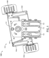
- Each adjustable headrest assembly 102 may include a headrest center bracket 104, a left vertical side plate track 106A positioned at a left side of the headrest center bracket 104, a left headrest side plate assembly 108A, a right vertical side plate track 106B positioned at a right side of the headrest center bracket 104, a right headrest side plate assembly 108B, a mounting plate assembly 110, and/or a seatback mount plate 112 having at least one (e.g., two) vertical track 162. As shown in FIG.
- the adjustable headrest assembly 102 is in an up and rotated position with the left headrest side plate assembly 108A and the right headrest side plate assembly 108B tilted forward. Additionally, the left headrest side plate assembly 108A is in a down position with the left headrest side plate assembly 108A positioned in a lower portion of the left vertical side plate track 106A. Additionally, the right headrest side plate assembly 108B is in an up position with the right headrest side plate assembly 108B positioned in an upper portion of the right vertical side plate track 106B.
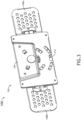
- FIG. 2 a rear perspective view of an exemplary position of the adjustable headrest assembly 102 of FIG. 1 is depicted according to the inventive concepts.
- the adjustable headrest assembly 102 is in a down and centered position with the left headrest side plate assembly 108A and the right headrest side plate assembly 108B tilted to be in line with the headrest center bracket 104.
- the left headrest side plate assembly 108A is in a centered position with the left headrest side plate assembly 108A positioned in a center portion of the left vertical side plate track 106A.
- the right headrest side plate assembly 108B is in a centered position with the right headrest side plate assembly 108B positioned in a center portion of the right vertical side plate track 106B.
- FIG. 3 a front perspective view of the position of the adjustable headrest assembly 102 of FIG. 2 is depicted according to the inventive concepts.
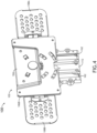
- FIG. 4 a front perspective view of an exemplary position of the adjustable headrest assembly 102 of FIG. 1 is depicted according to the inventive concepts.
- the adjustable headrest assembly 102 is in a fully up and centered position with the left headrest side plate assembly 108A and the right headrest side plate assembly 108B tilted to be in line with the headrest center bracket 104.
- the left headrest side plate assembly 108A is in a centered position with the left headrest side plate assembly 108A positioned in a center portion of the left vertical side plate track 106A.
- the right headrest side plate assembly 108B is in a centered position with the right headrest side plate assembly 108B positioned in a center portion of the right vertical side plate track 106B.
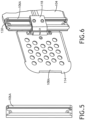
- FIG. 5 a view of one of the left vertical side plate track 106A or the right vertical side plate track 106B of the adjustable headrest assembly 102 of FIG. 1 is depicted according to the inventive concepts.
- the left vertical side plate track 106A may be positioned at a left side of the headrest center bracket 104.
- the right vertical side plate track 106B may be positioned at a right side of the headrest center bracket 104.
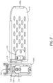
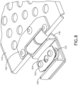
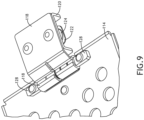
- FIG. 6-12 multiple views of the left headrest side plate assembly 108A and the right headrest side plate assembly 10B of the adjustable headrest assembly 102 of FIG. 1 are depicted according to the inventive concepts.
- Each of the left headrest side plate assembly 108A and the right headrest side plate assembly 10B may be engaged with one of the the left vertical side plate track 106A or the right vertical side plate track 106B.
- Each of the left headrest side plate assembly 108A and the right headrest side plate assembly 10B may include a headrest side plate 114 (e.g., a headrest side plate wing).
- the left headrest side plate 114 may be configured to move up and down relative to the left vertical side plate track 106A based on the engagement of the left headrest side plate assembly 108A with the left vertical side plate track 106A.
- the right headrest side plate 114 may be configured to move up and down relative to the right vertical side plate track 106B based on the engagement of the right headrest side plate assembly 108B with the right vertical side plate track 106B.
- the headrest side plates 114 may be configured to move up and down a full height of the headrest center bracket 104.
- Each of the left and right vertical side plate track 106A, 106B may have at least one stop pin 130.
- the left headrest side plate 114 may be configured to rotate fore and aft about an axis positioned along an edge (e.g., a left edge) of the head rest center bracket 104.
- the right headrest side plate 114 may be configured to rotate fore and aft about another axis positioned along another edge (e.g., a right edge) of the head rest center bracket 104, wherein the right headrest side plate 114 may be configured to rotate fore and aft independently of the left headrest side plate 114 being configured to rotate fore and aft.
- Each of the left headrest side plate assembly 108A and the right headrest side plate assembly 10B may further include: a clamp pin (e.g., a friction clamp pin 116) attached to the headrest side plate 114; a clamp (e.g., a friction clamp 118) rotatably engaged with the friction clamp pin 116 such that the headrest side plate 114 is able to rotate fore and aft about the axis; a torque block 120 attached to the friction clamp 118; a roller plate 122 attached to the torque block 120; at least one (e.g., two) roller 124 (e.g., at least one friction roller) positioned between the roller plate 122 and the torque block 120, wherein the at least one roller 124 engages with one of the left or right vertical side plate track 106A, 106B such that the headrest side plate 114 is able to move up and down relative to the headrest center bracket 104; and/or a headrest side plate doubler 126 attached to the headrest side plate 114 and the
- the torque block 120 may mount between the friction clamp and the rollers 124.
- the torque block 120 may translate any torque about the left or right vertical side plate track 106A, 106B into the headrest center bracket 104.
- the torque block 120 may serve as an attachment point for the rollers 124 and the roller plate 122.
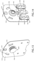
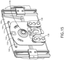
- FIG. 13-20 multiple views of the mounting plate assembly 110 of the adjustable headrest assembly 102 of FIG. 1 are depicted according to the inventive concepts.
- the mounting plate assembly 110 may serve as an alignment mechanism.
- the mounting plate assembly 110 may include a mounting plate 11.
- the mounting plate 111 may be positioned behind the headrest center bracket 104.
- the headrest center bracket 104 may be configured to rotate about a fore-aft axis positioned at a central location (e.g., extending through the friction pivot assembly 136) of the headrest center bracket 104.
- the fore-aft axis may extend laterally forward and aft between the mounting plate 111 and the headrest center bracket 104, wherein the left headrest side plate 108A and the right headrest side plate 108B rotate with the headrest center bracket 104.
- the mounting plate 111 may further include a center position detent 134.
- the mounting plate assembly 110 may further include at least one (e.g., two) roller assembly 138.
- Each of the at least one roller assembly 138 may include: a roller plate 140 attached to the mounting plate 111; and/or at least one (e.g., two) roller 142 positioned between the roller plate 140 and the mounting plate 111, wherein the at least one roller 142 engages with one of the at least one (e.g., two) vertical track 162 of the seatback mount plate 112 such that the mounting plate 111 is able to move up and down relative to the seatback mount plate 112.
- the mounting plate assembly 110 may further include a detent spring 144 attached to the headrest center bracket 104 and configured to slide along a surface of the mounting plate 111 as the headrest center bracket 104 rotates relative to the mounting plate 111.
- the detent spring 144 may be configured to reside in the center position detent 134 of the mounting plate 111 when a rotational position of the headrest center bracket 104 is centered.
- the detent spring 144 may be composed of spring plastic. The detent spring 144 may provide feedback to a passenger when the detent spring engages with the center position detent 134.
- the mounting plate assembly 110 may further include a friction pivot assembly 136 allowing the headrest center bracket 104 to rotate relative to the mounting plate 111 that uses force applied by a spring 154 to a washer 152 (e.g., a rubber washer, such as a silicone washer) to cause a friction resistance to an amount of rotation that occurs unless a passenger applies a rotative force to the adjustable headrest assembly 102.
- a friction pivot assembly 136 allowing the headrest center bracket 104 to rotate relative to the mounting plate 111 that uses force applied by a spring 154 to a washer 152 (e.g., a rubber washer, such as a silicone washer) to cause a friction resistance to an amount of rotation that occurs unless a passenger applies a rotative force to the adjustable headrest assembly 102.
- the friction pivot assembly 136 may include: a rotational pin 148 extending through and/or between the headrest center bracket 104 and the mounting plate 111, wherein the rotational pin 148 may allow the headrest center bracket 104 to rotate relative to the mounting plate 111; a first washer 150 (e.g.., a metal washer, such as a steel washer) positioned against the headrest center bracket 104 and around the rotational pin 148; a second washer 152 (e.g., a rubber washer, such as a silicone washer) positioned against the first washer 150 and around the rotational pin 148; a third washer 153 (e.g., a plastic washer, such as a non-nylon plastic washer) positioned against the second washer 152 and around the rotational pin 148; a spring 154 positioned against the third washer 153 and positioned around the rotational pin 148; a fourth washer 156 (e.g., a plastic washer, such as a non-nylon plastic washer) positioned between the spring 154
- the mounting plate assembly 110 may further include at least one (e.g., two) rotation stop opening 132.
- the headrest center bracket 104 may have at least one (e.g., two) rotation stop 146 (as shown in FIG. 16 ), wherein each of the at least one rotation stop 146 may extend into one of the at least one rotation stop opening 132 such that an amount of rotation of the headrest center bracket 104 relative to the mounting plate 111 is limited (e.g., limited to 5-30% rotation off center, such as 15% in either direction).
- embodiments of the inventive concepts disclosed herein may be directed to a system including an adjustable headrest assembly.
- At least one means one or a plurality of; for example, “at least one” may comprise one, two, three, ..., one hundred, or more.
- one or more means one or a plurality of; for example, “one or more” may comprise one, two, three, ..., one hundred, or more.
- zero or more means zero, one, or a plurality of; for example, “zero or more” may comprise zero, one, two, three, ..., one hundred, or more.
- the methods, operations, and/or functionality disclosed may be implemented as sets of instructions or software readable by a device. Further, it is understood that the specific order or hierarchy of steps in the methods, operations, and/or functionality disclosed are examples of exemplary approaches. Based upon design preferences, it is understood that the specific order or hierarchy of steps in the methods, operations, and/or functionality can be rearranged while remaining within the scope of the inventive concepts disclosed herein.
- the accompanying claims may present elements of the various steps in a sample order, and are not necessarily meant to be limited to the specific order or hierarchy presented.
- embodiments of the methods according to the inventive concepts disclosed herein may include one or more of the steps described herein. Further, such steps may be carried out in any desired order and two or more of the steps may be carried out simultaneously with one another. Two or more of the steps disclosed herein may be combined in a single step, and in some embodiments, one or more of the steps may be carried out as two or more sub-steps. Further, other steps or sub-steps may be carried in addition to, or as substitutes to one or more of the steps disclosed herein.
- inventive concepts disclosed herein are well adapted to carry out the objects and to attain the advantages mentioned herein as well as those inherent in the inventive concepts disclosed herein. While presently preferred embodiments of the inventive concepts disclosed herein have been described for purposes of this disclosure, it will be understood that numerous changes may be made which will readily suggest themselves to those skilled in the art and which are accomplished within the broad scope and coverage of the inventive concepts disclosed and claimed herein.
Landscapes
- Engineering & Computer Science (AREA)
- Aviation & Aerospace Engineering (AREA)
- Transportation (AREA)
- Mechanical Engineering (AREA)
- Seats For Vehicles (AREA)
Applications Claiming Priority (1)
| Application Number | Priority Date | Filing Date | Title |
|---|---|---|---|
| US17/669,000 US11926249B2 (en) | 2022-02-10 | 2022-02-10 | Adjustable head rest assembly and system |
Publications (3)
| Publication Number | Publication Date |
|---|---|
| EP4227221A2 true EP4227221A2 (de) | 2023-08-16 |
| EP4227221A3 EP4227221A3 (de) | 2023-08-23 |
| EP4227221B1 EP4227221B1 (de) | 2025-05-07 |
Family
ID=85222097
Family Applications (1)
| Application Number | Title | Priority Date | Filing Date |
|---|---|---|---|
| EP23155839.6A Active EP4227221B1 (de) | 2022-02-10 | 2023-02-09 | Verstellbare kopfstützenanordnung und system |
Country Status (2)
| Country | Link |
|---|---|
| US (1) | US11926249B2 (de) |
| EP (1) | EP4227221B1 (de) |
Families Citing this family (1)
| Publication number | Priority date | Publication date | Assignee | Title |
|---|---|---|---|---|
| EP3964442B1 (de) * | 2020-09-02 | 2023-12-27 | B/E Aerospace, Inc. | Belüftete einstellbare kopfstütze |
Family Cites Families (24)
| Publication number | Priority date | Publication date | Assignee | Title |
|---|---|---|---|---|
| DE1779181B1 (de) * | 1968-07-16 | 1972-03-09 | Happich Gmbh Gebr | Kopf und nackenstuetze fuer sitze |
| US5586810A (en) * | 1996-02-12 | 1996-12-24 | Liu; Yang-Ting | Adjustable headrest |
| US6467846B2 (en) | 2000-09-20 | 2002-10-22 | Robert Clough | Seat headrest |
| US7040705B2 (en) * | 2000-09-20 | 2006-05-09 | Robert Clough | Seat headrest |
| US7264313B2 (en) * | 2000-09-20 | 2007-09-04 | Robert Clough | Seat headrest |
| DE10215058C1 (de) | 2002-04-05 | 2003-07-24 | Recaro Aircraft Seating Gmbh | Kopfstütze für einen Sitz |
| KR20060120000A (ko) * | 2003-10-06 | 2006-11-24 | 비이 에어로스페이스 인코포레이티드 | 머리 받침 지지 조립체 |
| DE102004030933B3 (de) | 2004-06-25 | 2005-08-11 | Grammer Ag | Kopfstütze für einen Fahrgastsitz |
| FR2875190A1 (fr) | 2004-09-13 | 2006-03-17 | Cera | Appui-tete pourvu d'une aile en rotation a 45 degres |
| DE202006016277U1 (de) | 2006-10-21 | 2007-04-05 | Györy, Kálmán | Arretier und Verschlusskombinationseinrichtung für verstellbare Kopfstützen |
| FR2955808B1 (fr) | 2010-01-29 | 2015-06-26 | Airbus Operations Sas | Appui-tete de siege de passager d'aeronef |
| US8893333B2 (en) * | 2010-11-18 | 2014-11-25 | Allen Medical Systems, Inc. | Surgical head support apparatus |
| DE102011012161A1 (de) | 2011-02-23 | 2012-08-23 | GM Global Technology Operations LLC (n. d. Ges. d. Staates Delaware) | Rotationsvorrichtung, Kopfstütze, Fahrzeugsitz, Kraftfahrzeug und Verfahren hierzu |
| US8696065B2 (en) | 2012-01-05 | 2014-04-15 | Be Aerospace, Inc. | Adjustable headrest for an aircraft seat |
| FR2985466B1 (fr) | 2012-01-06 | 2014-01-24 | Peugeot Citroen Automobiles Sa | Appuie-tete perfectionne pour siege de vehicule |
| US9028000B2 (en) * | 2012-03-06 | 2015-05-12 | Sergio Millan | Seat headrest |
| SG2013026190A (en) * | 2013-04-08 | 2014-11-27 | Singapore Tech Aerospace Ltd | Headrest structure, headrest cushion and passenger seat |
| US10538185B2 (en) * | 2015-03-16 | 2020-01-21 | Southco, Inc. | Friction module, friction hinge, and adjustable headrest including the friction module and/or friction hinge |
| US9611041B2 (en) * | 2015-03-20 | 2017-04-04 | B/E Aerospace, Inc. | Passenger seat headrest |
| FR3054503A1 (fr) * | 2016-08-01 | 2018-02-02 | Zodiac Seats France | Tetiere oreiller pour siege de cabine d'aeronef |
| US10843608B2 (en) * | 2017-11-18 | 2020-11-24 | Madelyne Carlson | Personal shield devices, systems and methods |
| US10807719B2 (en) | 2019-02-19 | 2020-10-20 | B/E Aerospace, Inc. | Multi-position adjustable headrest assembly |
| US11267382B2 (en) * | 2019-12-12 | 2022-03-08 | Reinhold Industries, Inc. | Passenger seating headrest with friction assembly |
| CN211641957U (zh) | 2019-12-30 | 2020-10-09 | 扬州恒新座椅有限公司 | 一种前部头枕电动侧翼调节机构 |
-
2022
- 2022-02-10 US US17/669,000 patent/US11926249B2/en active Active
-
2023
- 2023-02-09 EP EP23155839.6A patent/EP4227221B1/de active Active
Also Published As
| Publication number | Publication date |
|---|---|
| US20230249598A1 (en) | 2023-08-10 |
| US11926249B2 (en) | 2024-03-12 |
| EP4227221A3 (de) | 2023-08-23 |
| EP4227221B1 (de) | 2025-05-07 |
Similar Documents
| Publication | Publication Date | Title |
|---|---|---|
| US10689119B2 (en) | Seat system | |
| US10399474B2 (en) | Multi-adjustable head restraint | |
| US11059393B2 (en) | Vehicle access seating | |
| US20180304789A1 (en) | Armrest module for automobile seat | |
| US11794904B2 (en) | Compact rotorcraft seating assembly with non-linear bucket guide channels | |
| US20100244478A1 (en) | Vehicle console with movable armrest | |
| US11214178B2 (en) | Pivoting seat assembly | |
| US7344195B2 (en) | Dampener for a vehicle seat recliner | |
| EP4227221A2 (de) | Verstellbare kopfstützenanordnung und system | |
| US10471863B2 (en) | Vehicle seat | |
| US20200406794A1 (en) | Adjustable seat assembly | |
| US11214179B2 (en) | Pivoting seat assembly | |
| US12043145B2 (en) | Seat for vehicle | |
| US4508385A (en) | Seat track assembly | |
| US11820256B2 (en) | Seat for a vehicle | |
| GB2426925A (en) | Vehicle seat upper back frame structure | |
| US7903180B2 (en) | Overhead mountable sliding video display assembly and method | |
| US5738475A (en) | Adjustable expansion rivet | |
| US11904733B2 (en) | Longitudinal adjuster and vehicle seat | |
| US12024296B2 (en) | Passenger seat with non-intrusive recline | |
| US20180134395A1 (en) | In-flight leveling system | |
| US9981576B2 (en) | End stop with free play elimination to improve stiffness | |
| US11225172B2 (en) | Laterally translating seat pedestal | |
| US10343570B1 (en) | Vehicle armrest mounting assembly and installation method | |
| CN208393192U (zh) | 中央扶手组件和车辆 |
Legal Events
| Date | Code | Title | Description |
|---|---|---|---|
| PUAI | Public reference made under article 153(3) epc to a published international application that has entered the european phase |
Free format text: ORIGINAL CODE: 0009012 |
|
| STAA | Information on the status of an ep patent application or granted ep patent |
Free format text: STATUS: THE APPLICATION HAS BEEN PUBLISHED |
|
| PUAL | Search report despatched |
Free format text: ORIGINAL CODE: 0009013 |
|
| AK | Designated contracting states |
Kind code of ref document: A2 Designated state(s): AL AT BE BG CH CY CZ DE DK EE ES FI FR GB GR HR HU IE IS IT LI LT LU LV MC ME MK MT NL NO PL PT RO RS SE SI SK SM TR |
|
| AK | Designated contracting states |
Kind code of ref document: A3 Designated state(s): AL AT BE BG CH CY CZ DE DK EE ES FI FR GB GR HR HU IE IS IT LI LT LU LV MC ME MK MT NL NO PL PT RO RS SE SI SK SM TR |
|
| RIC1 | Information provided on ipc code assigned before grant |
Ipc: B64D 11/06 20060101AFI20230719BHEP |
|
| STAA | Information on the status of an ep patent application or granted ep patent |
Free format text: STATUS: REQUEST FOR EXAMINATION WAS MADE |
|
| 17P | Request for examination filed |
Effective date: 20240223 |
|
| RBV | Designated contracting states (corrected) |
Designated state(s): AL AT BE BG CH CY CZ DE DK EE ES FI FR GB GR HR HU IE IS IT LI LT LU LV MC ME MK MT NL NO PL PT RO RS SE SI SK SM TR |
|
| GRAP | Despatch of communication of intention to grant a patent |
Free format text: ORIGINAL CODE: EPIDOSNIGR1 |
|
| STAA | Information on the status of an ep patent application or granted ep patent |
Free format text: STATUS: GRANT OF PATENT IS INTENDED |
|
| INTG | Intention to grant announced |
Effective date: 20241209 |
|
| GRAS | Grant fee paid |
Free format text: ORIGINAL CODE: EPIDOSNIGR3 |
|
| GRAA | (expected) grant |
Free format text: ORIGINAL CODE: 0009210 |
|
| STAA | Information on the status of an ep patent application or granted ep patent |
Free format text: STATUS: THE PATENT HAS BEEN GRANTED |
|
| AK | Designated contracting states |
Kind code of ref document: B1 Designated state(s): AL AT BE BG CH CY CZ DE DK EE ES FI FR GB GR HR HU IE IS IT LI LT LU LV MC ME MK MT NL NO PL PT RO RS SE SI SK SM TR |
|
| REG | Reference to a national code |
Ref country code: GB Ref legal event code: FG4D |
|
| REG | Reference to a national code |
Ref country code: CH Ref legal event code: EP |
|
| REG | Reference to a national code |
Ref country code: DE Ref legal event code: R096 Ref document number: 602023003245 Country of ref document: DE |
|
| REG | Reference to a national code |
Ref country code: IE Ref legal event code: FG4D |
|
| REG | Reference to a national code |
Ref country code: NL Ref legal event code: MP Effective date: 20250507 |
|
| PG25 | Lapsed in a contracting state [announced via postgrant information from national office to epo] |
Ref country code: PT Free format text: LAPSE BECAUSE OF FAILURE TO SUBMIT A TRANSLATION OF THE DESCRIPTION OR TO PAY THE FEE WITHIN THE PRESCRIBED TIME-LIMIT Effective date: 20250908 Ref country code: ES Free format text: LAPSE BECAUSE OF FAILURE TO SUBMIT A TRANSLATION OF THE DESCRIPTION OR TO PAY THE FEE WITHIN THE PRESCRIBED TIME-LIMIT Effective date: 20250507 Ref country code: FI Free format text: LAPSE BECAUSE OF FAILURE TO SUBMIT A TRANSLATION OF THE DESCRIPTION OR TO PAY THE FEE WITHIN THE PRESCRIBED TIME-LIMIT Effective date: 20250507 |
|
| REG | Reference to a national code |
Ref country code: LT Ref legal event code: MG9D |
|
| PG25 | Lapsed in a contracting state [announced via postgrant information from national office to epo] |
Ref country code: GR Free format text: LAPSE BECAUSE OF FAILURE TO SUBMIT A TRANSLATION OF THE DESCRIPTION OR TO PAY THE FEE WITHIN THE PRESCRIBED TIME-LIMIT Effective date: 20250808 Ref country code: NO Free format text: LAPSE BECAUSE OF FAILURE TO SUBMIT A TRANSLATION OF THE DESCRIPTION OR TO PAY THE FEE WITHIN THE PRESCRIBED TIME-LIMIT Effective date: 20250807 |
|
| PG25 | Lapsed in a contracting state [announced via postgrant information from national office to epo] |
Ref country code: NL Free format text: LAPSE BECAUSE OF FAILURE TO SUBMIT A TRANSLATION OF THE DESCRIPTION OR TO PAY THE FEE WITHIN THE PRESCRIBED TIME-LIMIT Effective date: 20250507 Ref country code: PL Free format text: LAPSE BECAUSE OF FAILURE TO SUBMIT A TRANSLATION OF THE DESCRIPTION OR TO PAY THE FEE WITHIN THE PRESCRIBED TIME-LIMIT Effective date: 20250507 |
|
| REG | Reference to a national code |
Ref country code: AT Ref legal event code: MK05 Ref document number: 1792243 Country of ref document: AT Kind code of ref document: T Effective date: 20250507 |
|
| PG25 | Lapsed in a contracting state [announced via postgrant information from national office to epo] |
Ref country code: BG Free format text: LAPSE BECAUSE OF FAILURE TO SUBMIT A TRANSLATION OF THE DESCRIPTION OR TO PAY THE FEE WITHIN THE PRESCRIBED TIME-LIMIT Effective date: 20250507 |
|
| PG25 | Lapsed in a contracting state [announced via postgrant information from national office to epo] |
Ref country code: HR Free format text: LAPSE BECAUSE OF FAILURE TO SUBMIT A TRANSLATION OF THE DESCRIPTION OR TO PAY THE FEE WITHIN THE PRESCRIBED TIME-LIMIT Effective date: 20250507 |
|
| PG25 | Lapsed in a contracting state [announced via postgrant information from national office to epo] |
Ref country code: AT Free format text: LAPSE BECAUSE OF FAILURE TO SUBMIT A TRANSLATION OF THE DESCRIPTION OR TO PAY THE FEE WITHIN THE PRESCRIBED TIME-LIMIT Effective date: 20250507 |
|
| PG25 | Lapsed in a contracting state [announced via postgrant information from national office to epo] |
Ref country code: RS Free format text: LAPSE BECAUSE OF FAILURE TO SUBMIT A TRANSLATION OF THE DESCRIPTION OR TO PAY THE FEE WITHIN THE PRESCRIBED TIME-LIMIT Effective date: 20250807 |
|
| PG25 | Lapsed in a contracting state [announced via postgrant information from national office to epo] |
Ref country code: IS Free format text: LAPSE BECAUSE OF FAILURE TO SUBMIT A TRANSLATION OF THE DESCRIPTION OR TO PAY THE FEE WITHIN THE PRESCRIBED TIME-LIMIT Effective date: 20250907 |
|
| PG25 | Lapsed in a contracting state [announced via postgrant information from national office to epo] |
Ref country code: LV Free format text: LAPSE BECAUSE OF FAILURE TO SUBMIT A TRANSLATION OF THE DESCRIPTION OR TO PAY THE FEE WITHIN THE PRESCRIBED TIME-LIMIT Effective date: 20250507 |
|
| PG25 | Lapsed in a contracting state [announced via postgrant information from national office to epo] |
Ref country code: DK Free format text: LAPSE BECAUSE OF FAILURE TO SUBMIT A TRANSLATION OF THE DESCRIPTION OR TO PAY THE FEE WITHIN THE PRESCRIBED TIME-LIMIT Effective date: 20250507 Ref country code: SM Free format text: LAPSE BECAUSE OF FAILURE TO SUBMIT A TRANSLATION OF THE DESCRIPTION OR TO PAY THE FEE WITHIN THE PRESCRIBED TIME-LIMIT Effective date: 20250507 |
|
| PG25 | Lapsed in a contracting state [announced via postgrant information from national office to epo] |
Ref country code: CZ Free format text: LAPSE BECAUSE OF FAILURE TO SUBMIT A TRANSLATION OF THE DESCRIPTION OR TO PAY THE FEE WITHIN THE PRESCRIBED TIME-LIMIT Effective date: 20250507 |
|
| PG25 | Lapsed in a contracting state [announced via postgrant information from national office to epo] |
Ref country code: EE Free format text: LAPSE BECAUSE OF FAILURE TO SUBMIT A TRANSLATION OF THE DESCRIPTION OR TO PAY THE FEE WITHIN THE PRESCRIBED TIME-LIMIT Effective date: 20250507 |
|
| PG25 | Lapsed in a contracting state [announced via postgrant information from national office to epo] |
Ref country code: SK Free format text: LAPSE BECAUSE OF FAILURE TO SUBMIT A TRANSLATION OF THE DESCRIPTION OR TO PAY THE FEE WITHIN THE PRESCRIBED TIME-LIMIT Effective date: 20250507 |
|
| PG25 | Lapsed in a contracting state [announced via postgrant information from national office to epo] |
Ref country code: IT Free format text: LAPSE BECAUSE OF FAILURE TO SUBMIT A TRANSLATION OF THE DESCRIPTION OR TO PAY THE FEE WITHIN THE PRESCRIBED TIME-LIMIT Effective date: 20250507 |
|
| REG | Reference to a national code |
Ref country code: DE Ref legal event code: R097 Ref document number: 602023003245 Country of ref document: DE |
|
| PLBE | No opposition filed within time limit |
Free format text: ORIGINAL CODE: 0009261 |
|
| STAA | Information on the status of an ep patent application or granted ep patent |
Free format text: STATUS: NO OPPOSITION FILED WITHIN TIME LIMIT |
|
| REG | Reference to a national code |
Ref country code: CH Ref legal event code: L10 Free format text: ST27 STATUS EVENT CODE: U-0-0-L10-L00 (AS PROVIDED BY THE NATIONAL OFFICE) Effective date: 20260318 |
|
| PGFP | Annual fee paid to national office [announced via postgrant information from national office to epo] |
Ref country code: DE Payment date: 20260121 Year of fee payment: 4 |
|
| 26N | No opposition filed |
Effective date: 20260210 |
|
| PGFP | Annual fee paid to national office [announced via postgrant information from national office to epo] |
Ref country code: FR Payment date: 20260121 Year of fee payment: 4 |