EP4227167B1 - Herstellungsverfahren für eine kraftfahrzeugkarosserie mit einer crashenergie absorbierenden komponente - Google Patents
Herstellungsverfahren für eine kraftfahrzeugkarosserie mit einer crashenergie absorbierenden komponente Download PDFInfo
- Publication number
- EP4227167B1 EP4227167B1 EP21877179.8A EP21877179A EP4227167B1 EP 4227167 B1 EP4227167 B1 EP 4227167B1 EP 21877179 A EP21877179 A EP 21877179A EP 4227167 B1 EP4227167 B1 EP 4227167B1
- Authority
- EP
- European Patent Office
- Prior art keywords
- automotive
- coating
- crashworthiness
- energy absorbing
- coating film
- Prior art date
- Legal status (The legal status is an assumption and is not a legal conclusion. Google has not performed a legal analysis and makes no representation as to the accuracy of the status listed.)
- Active
Links
Images




Classifications
-
- B—PERFORMING OPERATIONS; TRANSPORTING
- B62—LAND VEHICLES FOR TRAVELLING OTHERWISE THAN ON RAILS
- B62D—MOTOR VEHICLES; TRAILERS
- B62D21/00—Understructures, i.e. chassis frame on which a vehicle body may be mounted
- B62D21/15—Understructures, i.e. chassis frame on which a vehicle body may be mounted having impact absorbing means, e.g. a frame designed to permanently or temporarily change shape or dimension upon impact with another body
-
- C—CHEMISTRY; METALLURGY
- C25—ELECTROLYTIC OR ELECTROPHORETIC PROCESSES; APPARATUS THEREFOR
- C25D—PROCESSES FOR THE ELECTROLYTIC OR ELECTROPHORETIC PRODUCTION OF COATINGS; ELECTROFORMING; APPARATUS THEREFOR
- C25D7/00—Electroplating characterised by the article coated
- C25D7/04—Tubes; Rings; Hollow bodies
-
- B—PERFORMING OPERATIONS; TRANSPORTING
- B60—VEHICLES IN GENERAL
- B60R—VEHICLES, VEHICLE FITTINGS, OR VEHICLE PARTS, NOT OTHERWISE PROVIDED FOR
- B60R19/00—Wheel guards; Radiator guards, e.g. grilles; Obstruction removers; Fittings damping bouncing force in collisions
- B60R19/02—Bumpers, i.e. impact receiving or absorbing members for protecting vehicles or fending off blows from other vehicles or objects
- B60R19/24—Arrangements for mounting bumpers on vehicles
- B60R19/26—Arrangements for mounting bumpers on vehicles comprising yieldable mounting means
- B60R19/34—Arrangements for mounting bumpers on vehicles comprising yieldable mounting means destroyed upon impact, e.g. one-shot type
-
- B—PERFORMING OPERATIONS; TRANSPORTING
- B62—LAND VEHICLES FOR TRAVELLING OTHERWISE THAN ON RAILS
- B62D—MOTOR VEHICLES; TRAILERS
- B62D21/00—Understructures, i.e. chassis frame on which a vehicle body may be mounted
- B62D21/15—Understructures, i.e. chassis frame on which a vehicle body may be mounted having impact absorbing means, e.g. a frame designed to permanently or temporarily change shape or dimension upon impact with another body
- B62D21/152—Front or rear frames
-
- C—CHEMISTRY; METALLURGY
- C09—DYES; PAINTS; POLISHES; NATURAL RESINS; ADHESIVES; COMPOSITIONS NOT OTHERWISE PROVIDED FOR; APPLICATIONS OF MATERIALS NOT OTHERWISE PROVIDED FOR
- C09D—COATING COMPOSITIONS, e.g. PAINTS, VARNISHES OR LACQUERS; FILLING PASTES; CHEMICAL PAINT OR INK REMOVERS; INKS; CORRECTING FLUIDS; WOODSTAINS; PASTES OR SOLIDS FOR COLOURING OR PRINTING; USE OF MATERIALS THEREFOR
- C09D5/00—Coating compositions, e.g. paints, varnishes or lacquers, characterised by their physical nature or the effects produced; Filling pastes
- C09D5/44—Coating compositions, e.g. paints, varnishes or lacquers, characterised by their physical nature or the effects produced; Filling pastes for electrophoretic applications
-
- F—MECHANICAL ENGINEERING; LIGHTING; HEATING; WEAPONS; BLASTING
- F16—ENGINEERING ELEMENTS AND UNITS; GENERAL MEASURES FOR PRODUCING AND MAINTAINING EFFECTIVE FUNCTIONING OF MACHINES OR INSTALLATIONS; THERMAL INSULATION IN GENERAL
- F16F—SPRINGS; SHOCK-ABSORBERS; MEANS FOR DAMPING VIBRATION
- F16F7/00—Vibration-dampers; Shock-absorbers
-
- F—MECHANICAL ENGINEERING; LIGHTING; HEATING; WEAPONS; BLASTING
- F16—ENGINEERING ELEMENTS AND UNITS; GENERAL MEASURES FOR PRODUCING AND MAINTAINING EFFECTIVE FUNCTIONING OF MACHINES OR INSTALLATIONS; THERMAL INSULATION IN GENERAL
- F16F—SPRINGS; SHOCK-ABSORBERS; MEANS FOR DAMPING VIBRATION
- F16F7/00—Vibration-dampers; Shock-absorbers
- F16F7/12—Vibration-dampers; Shock-absorbers using plastic deformation of members
-
- B—PERFORMING OPERATIONS; TRANSPORTING
- B60—VEHICLES IN GENERAL
- B60Y—INDEXING SCHEME RELATING TO ASPECTS CROSS-CUTTING VEHICLE TECHNOLOGY
- B60Y2306/00—Other features of vehicle sub-units
- B60Y2306/01—Reducing damages in case of crash, e.g. by improving battery protection
Definitions
- the present invention relates to a method of manufacturing an automotive body including an automotive crashworthiness energy absorption part, and more particularly to a method of manufacturing an automotive body including an automotive crashworthiness energy absorption part having a high crashworthiness energy absorbing effect of causing axial crushing when a crashworthiness load is input from the front or the rear of the automotive body.
- Patent Literature 1 discloses a technique for improving bending strength and torsional stiffness of an automotive structural member, and improving rigidity and collision safety of an automotive body while suppressing an increase in weight by filling a foam filler in the entire internal cross section of an automotive structural member having a structure in which hat-shaped section parts such as a side sill, a floor member, and a pillar are aligned in a direction of a top portion and a flange portion is overlapped to form a closed space therein.
- hat-shaped section parts such as a side sill, a floor member, and a pillar are aligned in a direction of a top portion and a flange portion is overlapped to form a closed space therein.
- Patent Literature 2 discloses a technique in which, when filling a highly rigid foam into the entire internal space of a closed section structure such as a pillar with hat-shaped section parts facing each other and a flange portion aligned, the highly rigid foam is fixed by a compression counter force due to filling and foaming of the highly rigid foam, and vibration damping performance for suppressing transmission of vibration sound is improved, and strength, rigidity, and crashworthiness energy absorption performance are improved.
- Patent Literature 3 discloses a metal-CFRP composite material in which a reinforcing material made of CFRP in which a plurality of fiber layers are laminated is bonded to a surface of a metal member with a thermosetting adhesive, and in order to relax residual shear stress generated in the thermosetting adhesive due to a linear expansion coefficient difference between a metal member and the reinforcing material after bonding, the metal-CFRP composite material has a structure including a residual shear stress decreasing portion in which a thickness gradually decreases from a main body portion toward an end edge of the reinforcing material.
- Patent Literature 4 discloses an automobile part that includes a front side member including an FRP energy absorbing portion having a cylindrical cross section that is sequentially crushed from an input end side by an input load from an axial direction, and a support portion that is connected to the FRP energy absorbing portion, is formed of FRP, and is joined to automotive parts, in which in the energy absorption portion, reinforcement fibers are oriented equally in a longitudinal direction of the front side member and a direction perpendicular to the longitudinal direction, and the support portion is capable of integral forming in which reinforcing fibers are oriented with isotropy.
- KR 2004 0104765 A describes a method of manufacturing an automotive body, the method comprising a part manufacturing process of manufacturing the automotive crashworthiness energy absorbing part; and a body assembly process of assembling the automotive body by attaching the automotive crashworthiness energy absorbing part manufactured in the part manufacturing process to a portion of the automotive body, wherein the part manufacturing process includes: a pre-coated part manufacturing process of manufacturing a pre-coated part including a tubular member formed using a hat-shaped section member including a top portion and a side wall portion, and a coating part having quality of material with a strength lower than that of the tubular member, the coating part being disposed with a gap on an outer surface of a portion including a corner connecting the top portion and the side wall portion in the tubular member to form a coating film; and a coating film forming process of forming a coating film by forming a coating layer by electrodeposition coating in an electrodeposition process in at least the gap in the pre-coated part, and thermally curing
- Patent Literature 1 and Patent Literature 2 by filling a foamed filler or a foam in an automobile part, strength against bending deformation, crashworthiness energy absorbing performance, and rigidity against torsional deformation of the automobile part can be improved, and deformation of the automobile part can be suppressed.
- Patent Literatures 3 and 4 it is possible to improve bending strength by bonding CFRP to a metal surface, and it is possible to reduce the number of part assembling man-hours and reduce the weight increase due to reduction of the number of fastening parts by integrally manufacturing parts in consideration of orientation of CFRP itself.
- CFRP even when CFRP is applied to an axially-crushed part accompanied by deformation, CFRP has high strength but remarkably low ductility, and thus there is a problem that folding and fracture of CFRP occur as soon as bellows-shaped deformation is started, and crashworthiness energy absorption performance is not improved. Furthermore, there is also a problem that the cost of CFRP is significantly high.
- the present invention has been made in view of the above problems, and it is an object of the present invention to provide a method of manufacturing an automotive body including an automotive crashworthiness energy absorbing part, such as a front side member or a crash box, in which when a crashworthiness load is input from the front or the rear of the automotive body to cause axial crushing, an absorption effect of crashworthiness energy is improved, additional production processes can be reduced, and a production cost does not greatly increase.
- an automotive crashworthiness energy absorbing part such as a front side member or a crash box
- the inventors have intensively studied a method of solving the above problems, and have found that by utilizing an electrodeposition paint generally used in a coating process of an automobile part manufacturing, an absorption effect of crashworthiness energy can be improved without requiring an additional process of filling the entire cross section of the part without gaps with a filler such as a foamed resin.
- the present invention has been made based on such findings, and specifically includes the following configurations.
- a method of manufacturing an automotive body including an automotive crashworthiness energy absorbing part is the method of manufacturing the automotive body including the automotive crashworthiness energy absorbing part that absorbs crashworthiness energy by being axially crushed when a crashworthiness load is input from a front side or a rear side of the automotive body.
- the method includes: a part manufacturing process of manufacturing the automotive crashworthiness energy absorbing part; and a body assembly process of assembling the automotive body by attaching the automotive crashworthiness energy absorbing part manufactured in the part manufacturing process to a front portion or a rear portion of the automotive body, wherein the part manufacturing process includes: a pre-coated part manufacturing process of manufacturing a pre-coated part including a tubular member formed using a hat-shaped section member including a top portion and a side wall portion, and a coating part having quality of material with a strength lower than that of the tubular member, the coating part being disposed with a gap of 0.2 mm to 3 mm on an outer surface of a portion including a corner connecting the top portion and the side wall portion in the tubular member to form a coating film; and a coating film forming process of forming a coating film by forming a coating layer by electrodeposition coating in an electrodeposition process in at least the gap in the pre-coated part, and thermally curing the coating layer by a subsequent paint baking process.
- an automotive body including an automotive crashworthiness energy absorbing part capable of improving buckling yield strength of a tubular member and generating buckling deformation in a bellows shape without reducing deformation resistance of the tubular member in a process of compressive deformation of the tubular member that absorbs crashworthiness energy due to axial crushing when a crashworthiness load is input from the front or rear of the automotive body.
- the automotive crashworthiness energy absorbing part in the present invention includes a coating part, a coating film having a target thickness can be formed by utilizing electrodeposition coating generally performed in a coating process of automotive part manufacturing, and an automotive body can be manufactured without greatly increasing production cost.
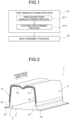
- a method of manufacturing an automotive body including an automotive crashworthiness energy absorbing part includes a part manufacturing process S1 of manufacturing an automotive crashworthiness energy absorbing part and a body assembly process S3 of assembling the automotive body by attaching the automotive crashworthiness energy absorbing part. Since the automotive crashworthiness energy absorbing part manufactured in the part manufacturing process S1 is a new part that has never existed before, the automotive crashworthiness energy absorbing part will first be described prior to the description of the manufacturing method. Note that, in the present specification and the drawings, elements having substantially the same function and configuration are denoted by the same reference signs, and redundant description is omitted.
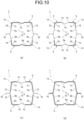
- An automotive crashworthiness energy absorbing part 1 (see FIG. 2 ) is provided at a front portion or a rear portion of an automotive body, and absorbs crashworthiness energy by axial crushing when a crashworthiness load is input from the front portion or the rear portion of the automotive body.
- a coating part 5 is provided on an outer surface side of a tubular member 3 formed using a hat-shaped section member, and a coating film 13 made of an electrodeposition paint is formed in a gap between the hat-shaped section member and the coating part 5.
- the tubular member 3 is made of a metal sheet such as a steel sheet, and is formed in a tubular shape by joining an outer part 7 having a hat cross-sectional shape (hat-shaped section member in the present invention) including a top portion 7a, a side wall portion 7b, and a corner 7c connecting the top portion 7a and the side wall portion 7b, and a flat plate-shaped inner part 9 at joining portions 10 which are flange portions of the outer part 7.
- hat cross-sectional shape hat-shaped section member in the present invention
- the automotive crashworthiness energy absorbing part 1 including such a tubular member 3 is configured to absorb crashworthiness energy by repeatedly generating buckling deformation in a bellows shape in the tubular member 3, in a process in which a crashworthiness load is input to an axial tip end of the automotive crashworthiness energy absorbing part 1 and the tubular member 3 exceeds buckling yield strength and is axially crashed.
- the coating part 5 is made of a metal sheet such as a steel sheet, is disposed on the outer surface side of the outer part 7 so as to form a gap 11 (see FIG. 4 ) of 0.2 mm to 3 mm in a portion including the corner 7c, and is joined to the side wall portion 7b by spot welding or the like at joining portions 12.
- the coating part 5 may be provided over the entire length in the axial direction of the outer part 7, but may be provided only in a range where bellows deformation is desired in the automotive crashworthiness energy absorbing part 1.
- the coating part 5 may be provided in this range of the outer part 7.
- the sheet thickness may be increased or a bead shape extending in the axial direction may be formed in order to increase the deformation strength.
- a coating film 13 by an electrodeposition paint is formed during electrodeposition coating, which is one of general coating processes in automotive part manufacturing ( FIG. 2 ).
- the type of the electrodeposition paint include a polyurethane type cationic electrodeposition paint, an epoxy type cationic electrodeposition paint, a urethane cationic electrodeposition paint, an acrylic anionic electrodeposition paint, and a fluororesin electrodeposition paint.
- the electrodeposition coating will be specifically described in a part manufacturing process S1 described later. The reason why the crashworthiness energy absorbing effect of the automotive crashworthiness energy absorbing part 1 is improved by forming such a coating film 13 will be described below.
- an automotive crashworthiness energy absorbing part including a tubular member formed of a metal sheet such as a steel sheet
- a crashworthiness load is input to an axial tip of the automotive crashworthiness energy absorbing part, and the tubular member absorbs crashworthiness energy by repeatedly generating buckling deformation in a bellows shape in a process in which the tubular member exceeds buckling yield strength and is axially crushed.
- the bellows-shaped bent portion has a small bending radius unique to the metal sheet, stress is concentrated on the outer surface side of the bent portion, and fracture is likely to occur. If fracture occurs in the bent portion in the process of axial crushing, the effect of absorbing crashworthiness energy is significantly reduced. Therefore, in order to improve the absorption effect of the crashworthiness energy, it is necessary to prevent the fracture generated in the tubular member buckling and deforming into the bellows shape.
- an object is interposed between the metal sheet and the metal sheet in the bent portion when the tubular member 3 is buckled and deformed into the bellows shape at the time of collision, and the bent portion is sandwiching the object and compressed to increase the bending radius of the bent portion and to prevent fracture of the bent tip.
- the object interposed between the metal sheet and the metal sheet is preferably as light as possible in order to avoid an increase in weight of the part.
- the portion having a high capability of absorbing the crashworthiness energy in the tubular member 3 is the corner 7c connecting the top portion 7a and the side wall portion 7b, but the corner 7c is also a portion that is most likely to be subjected to work hardening when the outer part 7 is press-formed, and the ductility is further lowered by the work hardening. Therefore, the bellows-shaped bent portion of the corner 7c is a portion where fracture is particularly likely to occur.
- the coating part 5 is provided on the outer surface side including the corner 7c of the outer part 7 such that the gap 11 (see FIG. 4 ) of 0.2 mm to 3 mm is generated between the coating part 5 and the outer surface, so that the electrodeposition paint enters the gap 11 during electrodeposition coating, and a coating layer having a predetermined thickness can be formed.
- the coating layer is cured in the baking process of electrodeposition coating and fixed to the gap 11 to form a coating film 13 (see FIG. 2 ).
- the coating film 13 is interposed outside the bellows-shaped bent portion to increase the bending radius and suppress the occurrence of fracture, so that the crashworthiness energy absorbing effect is improved. Note that the fact that the appropriate thickness of the coating film 13 is 0.2 mm to 3 mm will be described in Examples described later.
- the coating film 13 in the automotive crashworthiness energy absorbing part 1 also functions as a damping material that absorbs vibration.
- the coating film 13 absorbs vibration of an automotive engine mounted on the front side member, and the damping property is improved. The effect on the damping property will also be described in Examples described later.
- the coating part 5 since the coating part 5 is intended to form the coating film 13 having a predetermined thickness at the time of electrodeposition coating and is not required to have strength, it is preferable that the coating part 5 has lower strength and a thinner sheet thickness than the outer part 7 and the inner part 9. Furthermore, when the strength is too high, smooth bellows deformation is inhibited, and therefore, for example, a steel sheet of 440 MPa-class or less is preferable.
- the part manufacturing process S1 manufactures an automotive crashworthiness energy absorbing part 1 (see FIG. 2 ), and includes a pre-coated part manufacturing process S1-1 of manufacturing a pre-coated part 2 (see FIG. 4 ) in which a coating part 5 is provided on a tubular member 3, and a coating film forming process S1-2 of forming a coating film 13 on the pre-coated part 2.
- a pre-coated part manufacturing process S1-1 of manufacturing a pre-coated part 2 (see FIG. 4 ) in which a coating part 5 is provided on a tubular member 3, and a coating film forming process S1-2 of forming a coating film 13 on the pre-coated part 2.
- FIG. 5(a) is a cross-sectional view of the pre-coated part 2 manufactured in the pre-coated part manufacturing process S1-1
- FIG. 5(b) is a cross-sectional view of a part (automotive crashworthiness energy absorbing part 1) in which a coating film 13 is formed on the pre-co
- the pre-coated part manufacturing process S1-1 is a process of manufacturing the pre-coated part 2 (see FIG. 4 ) in which the coating part 5 is provided on the outer surface side of the tubular member 3 formed by joining the outer part 7 and the inner part 9 at the joining portion 10.
- the coating part 5 is installed outside the range including the corner 7c of the outer part 7 with a gap 11 of 0.2 mm to 3 mm from the outer surface of the outer part 7, and is joined to the outer surface of the side wall portion 7b by spot welding or the like (joining portion 12). Either the outer part 7 and the inner part 9 or the outer part 7 and the coating part 5 may be joined first.
- the coating film forming process S1-2 is a process of forming the coating film 13 in the gap 11 of the pre-coated part 2 manufactured in the pre-coated part manufacturing process S1-1.
- the coating film 13 is formed in the gap 11 by applying electrodeposition coating, which is generally performed in the process of manufacturing an automotive part, to the pre-coated part 2.
- electrodeposition coating which is generally performed in the process of manufacturing an automotive part
- an electrodeposition coating is applied to a steel sheet of an automotive part.
- a treatment of forming a coating layer on a steel sheet by electrodeposition and a treatment of curing the coating layer by a drying furnace (oven) or the like are performed.
- an example of electrodeposition coating will be described, and the correspondence with the coating film forming process S1-2 of the present embodiment will be described.
- an automotive part is subjected to a surface treatment such as degreasing, rinsing, or chemical conversion coating as a pretreatment, and then the automotive part subjected to the surface treatment is immersed in an electrodeposition tank containing an electrodeposition paint to conduct an object to be coated (automotive part) as a cathode and the electrodeposition paint as an anode, thereby forming a coating layer of the electrodeposition paint on a surface of a steel sheet (cationic electrodeposition coating).
- a surface treatment such as degreasing, rinsing, or chemical conversion coating
- An automotive part having a coating layer of an electrodeposition paint formed on a surface thereof by electric conduction in an electrodeposition tank is conveyed to a high-temperature drying furnace (oven) through a subsequent treatment such as rinsing, and the coating layer is cured by a baking treatment.
- the electrodeposition paint enters the gap 11, and the coating layer is formed by the subsequent conduction.
- the electrodeposition paint used for the automotive crashworthiness energy absorbing part 1 in the present embodiment is assumed to be a soft electrodeposition paint mainly used for inner parts (interior).
- the coating layer is cured through the baking treatment after the coating layer is formed, and the coating film 13 having a predetermined thickness is fixed to the gap 11 (see FIG. 5(b) ).
- a coating film of about 0.05 mm is formed on the surface of the steel sheet, but in the present embodiment, by providing the coating part 5 on the outer surface side of the outer part 7 in the pre-coated part 2, a coating film 13 having a thickness of 0.2 mm to 3 mm as illustrated in FIGS. 2 and 5(b) can be formed.
- the automotive crashworthiness energy absorbing part 1 is manufactured by forming the coating film 13 on the pre-coated part 2.
- the coating film 13 is preferably formed in a solid state over the entire region in the gap 11, it is also conceivable that the coating film 13 is formed in a state in which voids exist in a part of the gap 11, and even in such a case, the effect of the present invention can be exhibited as compared with a case where the coating film 13 is not present, so that the case where voids exist in a part of the gap 11 is not excluded.
- the automotive crashworthiness energy absorbing part 1 manufactured in the part manufacturing process S1 is attached to the front portion or the rear portion of the automotive body to assemble the automotive body.
- intermediate coating, topcoat base coating, and topcoat clear coating are applied to the automotive body to which the automotive crashworthiness energy absorbing part 1 is attached in order to improve weatherability, design, and the like.
- electrostatic coating of spraying a charged coating material to an object to be coated with a spray or the like
- intermediate coating has a function such as roughness concealment or light transmission suppression of an electrodeposition coating surface
- topcoat base coating and topcoat clear coating have a function of design property such as coloring or durability and the like.
- paints used for coating, topcoat base coating, and topcoat clear coating include polyester-melamine type paints, acryl melamine paints, acryl polyester melamine paints, alkyd polyester melamine paints, and the like.
- the automotive crashworthiness energy absorbing part 1 may be joined and assembled to an automotive body by spot welding, laser welding, or the like, and at that time, coating of the joining part may be peeled off in advance, or sealing may be performed before coating to prevent adhesion of coating material.
- the coating film 13 by the electrodeposition paint is formed in the gap 11 between the tubular member 3 and the coating part 5 at the time of electrodeposition coating generally performed in a coating process of automotive part manufacturing.
- the automotive crashworthiness energy absorbing part 1 in which the joining portion 12 of the coating part 5 is provided on the side wall portion 7b of the outer part 7 and the coating film 13 is formed over the outer surfaces of the top portion 7a, the corner 7c, and a part of the side wall portion 7b as illustrated in the cross-sectional view of FIG. 5 is exemplified, but the present invention is not limited thereto.
- a coating film may be formed on the outer surface mainly including the top portion 7a and the corner 7c with slight side wall portions 7b.
- the coating film 13 may be formed on the outer surface mainly including the corner 7c as illustrated in FIG. 7 .
- the joining portion 12 may be provided on each of the top portion 7a and the side wall portion 7b using two coating parts 5 ( FIG. 7(a) ), or the joining portion 12 may be provided on the side wall portion 7b by being brought into contact with or joined to the center of the top portion 7a using one coating part 5 ( FIG. 7(b) ).
- the coating film 13 may be formed on the outer surfaces of the side wall portion 7b and the corner 7c.
- the joining portion 12 may be provided in each of the top portion 7a and the side wall portion 7b using two coating parts 5 ( FIG. 8(a) ), or one coating part 5 may be brought into contact with or joined to the center of the top portion 7a, and the joining portion 12 may be provided in the side wall portion 7b ( FIG. 8(b) ).
- the hat-shaped section type coating part 5 as illustrated in FIG. 9 may be joined together with the outer part 7 and the inner part 9 at the joining portion 10.
- the tubular member 3 including the outer part 7 having the hat cross-sectional shape and the inner part 9 having the flat plate shape has been exemplified, but the present invention is not limited thereto, and can also be applied to a tubular member in which the hat-shaped section member illustrated in the example in FIG. 10 is opposed to each other and the flange portion is combined.
- FIG. 10(a) is an example in which the coating part 5 of the aspect illustrated in FIG. 6 is provided on each of the hat-shaped section members facing each other.
- FIG. 10(b) is an example in which the coating part 5 of the aspect illustrated in FIG. 7(a) is provided
- FIG. 10(c) is an example in which the coating part 5 of the aspect illustrated in FIG. 8(a) is provided
- FIG. 10(d) is an example in which the coating part 5 of the aspect illustrated in FIG. 9 is provided.
- the outer part 7 is denoted by the same reference numeral as that in FIGS. 5 to 9
- the inner part 9 is denoted by a reference numeral corresponding to the outer part 7.
- FIG. 10 illustrates an example in which the outer part 7 and the inner part 9 are hat-shaped section members having the same shape
- the inner part 9 may be a hat-shaped section member having a shape different from that of the outer part 7.
- one outer part or inner part may have the coating film 13 by the coating part 5, and the other inner part or outer part may be a conventional hat-shaped section member or a mountain folding part without a coating part.
- the automotive crashworthiness energy absorbing part 1 which is an intermediate manufactured part of the present invention, is a novel part, an experiment for confirming the crashworthiness energy absorbing effect of the automotive crashworthiness energy absorbing part 1 was conducted, and the results thereof will be described below.
- the automotive crashworthiness energy absorbing part 1 according to the present invention was used as a test body, and evaluation of absorption characteristics of crashworthiness energy by an axial crushing test, measurement of a frequency response function in an impact vibration test, and evaluation of damping characteristics by calculation of a natural frequency were performed.
- a load-stroke curve indicating a relationship between a load and a stroke (axial crushing deformation amount) was measured. And an image was taken by a high-speed camera to observe a deformed state and occurrence of fracture in the tubular member 3 when a load was input at a test speed of 17.8 m/s in the axial direction of a test body 21 having the tubular member 3, as illustrated in FIG. 11 , and the test body length (axial length L 0 of the test body 21) was axially crushed and deformed from 200 mm to 120 mm by 80 mm. Moreover, the absorbed energy at a stroke of up to 0 to 80 mm was determined from the measured load-stroke curve.
- an acceleration sensor (NP-3211 manufactured by ONO SOKKI CO., LTD.) was attached to the suspended test body 21 near the edge on the inner side of the top portion 7a of the outer part 7, impact vibration was applied to the inner side of the side wall portion 7b of the outer part 7 of the test body 21 with an impact hammer (GK-3100 manufactured by ONO SOKKI CO., LTD.), a vibration force and acceleration generated in the test body 21 were taken into an FFT analyzer (CF-7200A manufactured by ONO SOKKI CO., LTD.), and a frequency response function was calculated.
- the frequency response function was calculated by averaging processing by five strokes and curve fitting.
- vibration mode analysis was performed using the calculated frequency response function to determine the natural frequency in the same mode.
- FIG. 13 illustrates an example of a target vibration mode.
- FIG. 14 illustrates a structure and a shape of the test body 21 which is the automotive crashworthiness energy absorbing part 1 ( FIGS. 2 and 5(b) ) on which the coating film 13 is formed.
- the test body 21 includes the tubular member 3 in which the outer part 7 and the inner part 9 are joined by spot welding, and the coating part 5 is joined to the outer surface of the side wall portion 7b of the outer part 7.
- the coating film 13 is formed between the outer part 7 and the coating part 5.
- FIG. 14 illustrates an example in which the gap 11 between the top portion 7a and the coating part 5 was set to 3 mm, but in the present Example, the test body 21 in which the gap 11 was set to 2 mm, 1 mm, or 0.2 mm was also prepared, and a test was performed while changing the thickness of the coating film 13 formed in the gap 11.
- a test body 31 having a tubular member 3 and a coating part 5 as illustrated in FIG. 15 and having only a gap 11 in which a coating film 13 is not formed was prepared, and an axial crushing test and an impact vibration test were performed in the same manner as in the example.
- Table 2 illustrates the structure of the test body 21 as the example and the test body 31 as the comparative example, the conditions of the coating film, the test body weight, the calculation result of the absorbed energy when the axial crushing test is performed, and the result of the natural frequency obtained by the impact vibration test.
- Example 1 the test body 21 ( FIG. 14 ) including the coating part 5 and the coating film 13 was used, and the strength (quality of material) of the outer part 7 and the coating part 5 and the thickness of the coating film 13 were changed.
- Comparative Examples 1 to 4 the test body 31 ( FIG. 15 ) including the coating part 5 but having no coating film 13 formed was used, and the strength (quality of material) and the sheet thickness of the outer part 7 and the gap 11 between the outer part 7 and the coating part 5 were changed.
- the coating film 13 was formed without including the coating part 5.
- the coating part 5 and the coating film 13 are provided similarly to the test body 21, but the quality of material (780 MPa-class) of the coating part 5 exceeds the strength of the quality of materials (590 MPa-class) of the outer part 7 and the inner part 9.
- the test body weight illustrated in Table 2 is the sum of the weights of the outer part 7, the inner part 9, the coating part 5, and the coating film 13 for those having the coating part 5 and having the coating film 13 formed thereon (Examples 1 to 5 and Comparative Example 6), and is the sum of the weights of the outer part 7, the inner part 9, and the coating part 5 for those having no coating film 13 (Comparative Examples 1 to 4). Furthermore, the part (Comparative Example 5) not having the coating part 5 and having the coating film 13 formed thereon is the sum of the respective weights of the outer part 7, the inner part 9, and the coating film 13.
- the test body weight was 1.08 kgf, and the absorbed energy was 6.5 kJ. Moreover, the natural frequency was 155 Hz.
- Comparative Example 2 the sheet thickness of the outer part 7 and the gap between the outer part 7 and the coating part 5 were changed from those in Comparative Example 1, and the test body weight was 1.19 kgf and the absorbed energy was 7.0 kJ, which were larger than those in Comparative Example 1.
- the natural frequency was 175 Hz.
- the outer part 7 was a 980 MPa-class high-strength steel sheet, and the test body weight was 1.08 kgf.
- the absorbed energy was 8.1 kJ, which was further increased as compared with Comparative Example 2, but fracture occurred in the tubular member 3.
- the natural frequency was 155 Hz.
- the outer part 7 was a 1180 MPa-class high-strength steel sheet, and the test body weight was 1.09 kgf.
- the absorbed energy was 8.5 kJ, which was further increased as compared with Comparative Example 3, but fracture occurred in the tubular member 3.
- the natural frequency was 155 Hz.
- the outer part 7 was a 1180 MPa-class high-strength steel sheet, and the coating film 13 was formed without installing the coating part 5, and the thickness of the coating film 13 was 0.05 mm as in the conventional case.
- the test body weight was 0.96 kgf, and the absorbed energy was 8.7 kJ, which was larger than that in Comparative Example 4, but fracture occurred in the tubular member 3.
- the natural frequency was 195 Hz.
- the quality of material of the coating part 5 exceeds the strength of the quality of material of the outer part 7 and the inner part 9 (tubular member 3), and a coating film 13 having a thickness of 3 mm is further formed.
- the test body weight was 1.28 kgf, and the absorbed energy was 8.1 kJ, which was larger than that in Comparative Example 2, but the tubular member 3 did not become bellows and uneven deformation occurred.
- the natural frequency was 350 Hz.
- Example 1 the outer part 7 was a steel sheet having a steel sheet strength of 590 MPa-class, and the test body 21 having the coating film 13 of 3 mm in thickness was used.
- the absorbed energy in Example 1 was 11.1 kJ.
- Example 2 the same quality of material as in Example 1 was used, and the thickness of the coating film 13 was 2 mm.
- Example 3 similarly to Example 2, the thickness of the coating film 13 was set to 2 mm, and the steel sheet strength of the coating part 5 was set to 440 MPa-class.
- Example 4 the outer part 7 is a high-strength steel sheet having a steel sheet strength of 1180 MPa-class, and the thickness of the coating film 13 is 1 mm.
- the absorbed energy in Example 4 was 11.2 kJ, and fracture did not occur in the tubular member 3.
- Example 5 in the same material as in Example 4, the thickness of the coating film 13 was 0.2 mm, which is about the same as a laminate in a normal laminate steel sheet, and the test body weight was 1.10 kgf.
- Comparative Example 5 the tubular member was broken, but in Example 5, no fracture occurred.
- the appropriate thickness of the coating film 13 in the present invention was set to 0.2 mm to 3 mm.
- the automotive crashworthiness energy absorbing part 1 can efficiently improve the absorption effect of crashworthiness energy while suppressing an increase in weight in a case where a crashworthiness load is input in the axial direction and the automotive crashworthiness energy absorbing part 1 is axially crushed, and can improve the damping property by increasing the natural frequency when an impact is applied.
- the reason why the vibration damping property is improved by increasing the natural frequency is as follows.
- the natural frequency of the tubular member 3 that is a collision part like the front side member described above falls within the frequency range of vibration of the engine mounted on the member, sympathetic vibration occurs and the vibration increases.
- the frequency of vibration is 133 Hz in a 4-cylinder engine, 200 Hz in a 6-cylinder engine, and 267 Hz in an 8-cylinder engine. Therefore, when the natural frequency is about 280 Hz or more in Examples 1 to 5, the sympathetic vibration can be reliably prevented, and the damping property is improved.
- an automotive body including an automotive crashworthiness energy absorbing part such as a front side member or a crash box, in which an effect of absorbing crashworthiness energy due to axial crashing is improved when a crashworthiness load is input from the front or the rear of the automotive body, an additional production process can be reduced, and a production cost is not greatly increased.
Landscapes
- Engineering & Computer Science (AREA)
- Chemical & Material Sciences (AREA)
- Mechanical Engineering (AREA)
- General Engineering & Computer Science (AREA)
- Combustion & Propulsion (AREA)
- Transportation (AREA)
- Organic Chemistry (AREA)
- Materials Engineering (AREA)
- Life Sciences & Earth Sciences (AREA)
- Chemical Kinetics & Catalysis (AREA)
- Electrochemistry (AREA)
- Metallurgy (AREA)
- Molecular Biology (AREA)
- Health & Medical Sciences (AREA)
- Wood Science & Technology (AREA)
- Body Structure For Vehicles (AREA)
- Vibration Dampers (AREA)
- Laminated Bodies (AREA)
Claims (1)
- Herstellungsverfahren für eine Kraftfahrzeugkarosserie, die einen Absorptionsteil (1) für Aufprallsicherheitsenergie des Kraftfahrzeugs einschließt, der Aufprallsicherheitsenergie absorbiert, indem er axial zerdrückt wird, wenn eine Aufprallsicherheitslast von einer Vorderseite oder einer Rückseite der Kraftfahrzeugkarosserie eingeht, wobei das Verfahren umfasst:einen Teil-Herstellungsprozess zum Herstellen des Absorptionsteils für Aufprallsicherheitsenergie des Kraftfahrzeugs; undeinen Karosseriebauprozess zum Zusammenbauen der Kraftfahrzeugkarosserie durch Befestigen des in dem Teil-Herstellungsprozess hergestellten Absorptionsteils für Aufprallsicherheitsenergie des Kraftfahrzeugs an einem Vorderabschnitt oder einem Rückabschnitt der Kraftfahrzeugkarosserie,wobei der Teil-Herstellungsprozess einschließt:einen Herstellungsprozess für einen vorbeschichteten Teil zum Herstellen eines vorbeschichteten Teils (2), einschließlich:eines röhrenförmigen Elements (3), das unter Verwendung eines Elements mit hutförmigem Querschnitt gebildet wird und einen oberen Abschnitt (7a) und einen Seitenwandabschnitt (7b) einschließt, undeines Beschichtungsteils (5) mit einer Materialqualität mit einer geringeren Festigkeit als jene des röhrenförmigen Elements, wobei der Beschichtungsteil mit einem Spalt von 0,2 mm bis 3 mm auf einer Außenfläche eines Abschnitts angeordnet ist, der eine Ecke einschließt, die den oberen Abschnitt und den Seitenwandabschnitt in dem röhrenförmigen Element verbindet, um einen Beschichtungsfilm (13) zu bilden; undeinen Beschichtungsfilm-Bildungsprozess zum Bilden eines Beschichtungsfilms mittels:
Bilden einer Beschichtungsschicht durch Elektrotauchbeschichten in einem Elektrotauchprozess in zumindest dem Spalt in dem vorbeschichteten Teil durch Eintauchen des vorbeschichteten Teils in einem Elektrotauchbehälter, der einen Elektrotauchlack enthält,wobei der Elektrotauchlack einer von einem kationischen Elektrotauchlack vom Polyurethan-Typ, einem kationischen Elektrotauchlack vom Epoxid-Typ, einem kationischen Urethan-Elektrotauchlack, einem anionischen Acryl-Elektrotauchlack und einem Fluorharz-Elektrotauchlack ist, und
thermisches Aushärten der Beschichtungsschicht durch einen anschließenden Lackeinbrennprozess.
Applications Claiming Priority (2)
| Application Number | Priority Date | Filing Date | Title |
|---|---|---|---|
| JP2020168982A JP7238874B2 (ja) | 2020-10-06 | 2020-10-06 | 自動車用衝突エネルギー吸収部品を有する車体の製造方法 |
| PCT/JP2021/022874 WO2022074875A1 (ja) | 2020-10-06 | 2021-06-16 | 自動車用衝突エネルギー吸収部品を有する車体の製造方法 |
Publications (3)
| Publication Number | Publication Date |
|---|---|
| EP4227167A1 EP4227167A1 (de) | 2023-08-16 |
| EP4227167A4 EP4227167A4 (de) | 2024-04-10 |
| EP4227167B1 true EP4227167B1 (de) | 2025-01-22 |
Family
ID=81125816
Family Applications (1)
| Application Number | Title | Priority Date | Filing Date |
|---|---|---|---|
| EP21877179.8A Active EP4227167B1 (de) | 2020-10-06 | 2021-06-16 | Herstellungsverfahren für eine kraftfahrzeugkarosserie mit einer crashenergie absorbierenden komponente |
Country Status (7)
| Country | Link |
|---|---|
| US (1) | US20230407511A1 (de) |
| EP (1) | EP4227167B1 (de) |
| JP (1) | JP7238874B2 (de) |
| KR (1) | KR102839592B1 (de) |
| CN (1) | CN116249638A (de) |
| MX (1) | MX2023003865A (de) |
| WO (1) | WO2022074875A1 (de) |
Families Citing this family (1)
| Publication number | Priority date | Publication date | Assignee | Title |
|---|---|---|---|---|
| JP7758010B2 (ja) * | 2022-11-07 | 2025-10-22 | Jfeスチール株式会社 | 車体骨格部品及び該車体骨格部品の製造方法 |
Family Cites Families (15)
| Publication number | Priority date | Publication date | Assignee | Title |
|---|---|---|---|---|
| JP3620340B2 (ja) | 1999-05-12 | 2005-02-16 | 東海ゴム工業株式会社 | 高剛性発泡体充填構造体 |
| JP3928371B2 (ja) * | 2001-05-16 | 2007-06-13 | 日産自動車株式会社 | 自動車のサイドシル部構造 |
| KR20040104765A (ko) * | 2003-06-03 | 2004-12-13 | 현대자동차주식회사 | 차체의 측면 외측패널 구조 |
| JP4462978B2 (ja) | 2004-03-26 | 2010-05-12 | 日産自動車株式会社 | 自動車のエネルギー吸収構造 |
| JP2006240134A (ja) | 2005-03-04 | 2006-09-14 | Nissan Motor Co Ltd | 自動車用構造部材及びその製造方法 |
| JP2008162427A (ja) * | 2006-12-28 | 2008-07-17 | Daihatsu Motor Co Ltd | サイドメンバの補強構造 |
| JP5104264B2 (ja) * | 2007-12-07 | 2012-12-19 | トヨタ車体株式会社 | 自動車のピラー構造 |
| EP2159136A1 (de) * | 2008-09-01 | 2010-03-03 | Sika Technology AG | Verbindung mit Klebestreifen oder Klebepunkten |
| US20160177022A1 (en) * | 2014-12-18 | 2016-06-23 | Axalta Coating Systems Ip Co., Llc | Crosslinking components for electrocoat compositions, electrocoat compositions, and processes for forming a layer of an electrocoat composition on a surface of a substrate |
| JP6276230B2 (ja) | 2015-09-24 | 2018-02-07 | 本田技研工業株式会社 | 自動車ボディの強度剛性向上方法 |
| JP6315292B2 (ja) * | 2016-02-04 | 2018-04-25 | マツダ株式会社 | 車両のフレーム構造 |
| JP6631560B2 (ja) | 2017-03-02 | 2020-01-15 | Jfeスチール株式会社 | 自動車用衝突エネルギー吸収部品 |
| JP6729762B1 (ja) | 2019-05-28 | 2020-07-22 | Jfeスチール株式会社 | 自動車用衝突エネルギー吸収部品およびその製造方法 |
| JP7120175B2 (ja) * | 2019-07-18 | 2022-08-17 | Jfeスチール株式会社 | 自動車用衝突エネルギー吸収部品、該自動車用衝突エネルギー吸収部品の製造方法 |
| JP7238867B2 (ja) * | 2020-08-18 | 2023-03-14 | Jfeスチール株式会社 | 自動車用衝突エネルギー吸収部品、該自動車用衝突エネルギー吸収部品の製造方法 |
-
2020
- 2020-10-06 JP JP2020168982A patent/JP7238874B2/ja active Active
-
2021
- 2021-06-16 US US18/029,816 patent/US20230407511A1/en active Pending
- 2021-06-16 WO PCT/JP2021/022874 patent/WO2022074875A1/ja not_active Ceased
- 2021-06-16 MX MX2023003865A patent/MX2023003865A/es unknown
- 2021-06-16 EP EP21877179.8A patent/EP4227167B1/de active Active
- 2021-06-16 KR KR1020237010955A patent/KR102839592B1/ko active Active
- 2021-06-16 CN CN202180067681.1A patent/CN116249638A/zh active Pending
Also Published As
| Publication number | Publication date |
|---|---|
| WO2022074875A1 (ja) | 2022-04-14 |
| EP4227167A4 (de) | 2024-04-10 |
| CN116249638A (zh) | 2023-06-09 |
| MX2023003865A (es) | 2023-04-18 |
| US20230407511A1 (en) | 2023-12-21 |
| KR20230057467A (ko) | 2023-04-28 |
| EP4227167A1 (de) | 2023-08-16 |
| JP2022061164A (ja) | 2022-04-18 |
| KR102839592B1 (ko) | 2025-07-28 |
| JP7238874B2 (ja) | 2023-03-14 |
Similar Documents
| Publication | Publication Date | Title |
|---|---|---|
| EP4201752B1 (de) | Kollisionsenergieabsorptionskomponente für ein kraftfahrzeug und verfahren zur herstellung der kollisionsenergieabsorptionskomponente für ein kraftfahrzeug | |
| KR102519996B1 (ko) | 자동차용 충돌 에너지 흡수 부품 및 그의 제조 방법 | |
| EP4001059B1 (de) | Kollisionsenergieabsorptionsbauteil für kraftfahrzeuge und verfahren zur herstellung dieses kollisionsenergieabsorptionsbauteils für kraftfahrzeuge | |
| KR102602085B1 (ko) | 자동차용 충돌 에너지 흡수 부품 및 그의 제조 방법 | |
| US20100196736A1 (en) | Vibration-damping composite component | |
| EP4227167A1 (de) | Herstellungsverfahren für eine kraftfahrzeugkarosserie mit einer crashenergie absorbierenden komponente | |
| JP7140094B2 (ja) | 自動車用衝突エネルギー吸収部品を有する車体の製造方法 | |
| JP7758010B2 (ja) | 車体骨格部品及び該車体骨格部品の製造方法 |
Legal Events
| Date | Code | Title | Description |
|---|---|---|---|
| STAA | Information on the status of an ep patent application or granted ep patent |
Free format text: STATUS: THE INTERNATIONAL PUBLICATION HAS BEEN MADE |
|
| PUAI | Public reference made under article 153(3) epc to a published international application that has entered the european phase |
Free format text: ORIGINAL CODE: 0009012 |
|
| STAA | Information on the status of an ep patent application or granted ep patent |
Free format text: STATUS: REQUEST FOR EXAMINATION WAS MADE |
|
| 17P | Request for examination filed |
Effective date: 20230404 |
|
| AK | Designated contracting states |
Kind code of ref document: A1 Designated state(s): AL AT BE BG CH CY CZ DE DK EE ES FI FR GB GR HR HU IE IS IT LI LT LU LV MC MK MT NL NO PL PT RO RS SE SI SK SM TR |
|
| DAV | Request for validation of the european patent (deleted) | ||
| DAX | Request for extension of the european patent (deleted) | ||
| A4 | Supplementary search report drawn up and despatched |
Effective date: 20240311 |
|
| RIC1 | Information provided on ipc code assigned before grant |
Ipc: F16F 7/00 20060101ALI20240304BHEP Ipc: B62D 21/15 20060101ALI20240304BHEP Ipc: B60R 19/34 20060101AFI20240304BHEP |
|
| GRAP | Despatch of communication of intention to grant a patent |
Free format text: ORIGINAL CODE: EPIDOSNIGR1 |
|
| STAA | Information on the status of an ep patent application or granted ep patent |
Free format text: STATUS: GRANT OF PATENT IS INTENDED |
|
| INTG | Intention to grant announced |
Effective date: 20240919 |
|
| GRAS | Grant fee paid |
Free format text: ORIGINAL CODE: EPIDOSNIGR3 |
|
| GRAA | (expected) grant |
Free format text: ORIGINAL CODE: 0009210 |
|
| STAA | Information on the status of an ep patent application or granted ep patent |
Free format text: STATUS: THE PATENT HAS BEEN GRANTED |
|
| AK | Designated contracting states |
Kind code of ref document: B1 Designated state(s): AL AT BE BG CH CY CZ DE DK EE ES FI FR GB GR HR HU IE IS IT LI LT LU LV MC MK MT NL NO PL PT RO RS SE SI SK SM TR |
|
| REG | Reference to a national code |
Ref country code: GB Ref legal event code: FG4D |
|
| REG | Reference to a national code |
Ref country code: CH Ref legal event code: EP |
|
| REG | Reference to a national code |
Ref country code: DE Ref legal event code: R096 Ref document number: 602021025244 Country of ref document: DE |
|
| REG | Reference to a national code |
Ref country code: IE Ref legal event code: FG4D |
|
| REG | Reference to a national code |
Ref country code: NL Ref legal event code: MP Effective date: 20250122 |
|
| PG25 | Lapsed in a contracting state [announced via postgrant information from national office to epo] |
Ref country code: NL Free format text: LAPSE BECAUSE OF FAILURE TO SUBMIT A TRANSLATION OF THE DESCRIPTION OR TO PAY THE FEE WITHIN THE PRESCRIBED TIME-LIMIT Effective date: 20250122 |
|
| PG25 | Lapsed in a contracting state [announced via postgrant information from national office to epo] |
Ref country code: RS Free format text: LAPSE BECAUSE OF FAILURE TO SUBMIT A TRANSLATION OF THE DESCRIPTION OR TO PAY THE FEE WITHIN THE PRESCRIBED TIME-LIMIT Effective date: 20250422 |
|
| PG25 | Lapsed in a contracting state [announced via postgrant information from national office to epo] |
Ref country code: FI Free format text: LAPSE BECAUSE OF FAILURE TO SUBMIT A TRANSLATION OF THE DESCRIPTION OR TO PAY THE FEE WITHIN THE PRESCRIBED TIME-LIMIT Effective date: 20250122 |
|
| PG25 | Lapsed in a contracting state [announced via postgrant information from national office to epo] |
Ref country code: PL Free format text: LAPSE BECAUSE OF FAILURE TO SUBMIT A TRANSLATION OF THE DESCRIPTION OR TO PAY THE FEE WITHIN THE PRESCRIBED TIME-LIMIT Effective date: 20250122 |
|
| PGFP | Annual fee paid to national office [announced via postgrant information from national office to epo] |
Ref country code: DE Payment date: 20250624 Year of fee payment: 5 |
|
| PG25 | Lapsed in a contracting state [announced via postgrant information from national office to epo] |
Ref country code: ES Free format text: LAPSE BECAUSE OF FAILURE TO SUBMIT A TRANSLATION OF THE DESCRIPTION OR TO PAY THE FEE WITHIN THE PRESCRIBED TIME-LIMIT Effective date: 20250122 |
|
| REG | Reference to a national code |
Ref country code: LT Ref legal event code: MG9D |
|
| PG25 | Lapsed in a contracting state [announced via postgrant information from national office to epo] |
Ref country code: NO Free format text: LAPSE BECAUSE OF FAILURE TO SUBMIT A TRANSLATION OF THE DESCRIPTION OR TO PAY THE FEE WITHIN THE PRESCRIBED TIME-LIMIT Effective date: 20250422 Ref country code: IS Free format text: LAPSE BECAUSE OF FAILURE TO SUBMIT A TRANSLATION OF THE DESCRIPTION OR TO PAY THE FEE WITHIN THE PRESCRIBED TIME-LIMIT Effective date: 20250522 |
|
| REG | Reference to a national code |
Ref country code: AT Ref legal event code: MK05 Ref document number: 1761258 Country of ref document: AT Kind code of ref document: T Effective date: 20250122 |
|
| PG25 | Lapsed in a contracting state [announced via postgrant information from national office to epo] |
Ref country code: HR Free format text: LAPSE BECAUSE OF FAILURE TO SUBMIT A TRANSLATION OF THE DESCRIPTION OR TO PAY THE FEE WITHIN THE PRESCRIBED TIME-LIMIT Effective date: 20250122 |
|
| PG25 | Lapsed in a contracting state [announced via postgrant information from national office to epo] |
Ref country code: LV Free format text: LAPSE BECAUSE OF FAILURE TO SUBMIT A TRANSLATION OF THE DESCRIPTION OR TO PAY THE FEE WITHIN THE PRESCRIBED TIME-LIMIT Effective date: 20250122 Ref country code: PT Free format text: LAPSE BECAUSE OF FAILURE TO SUBMIT A TRANSLATION OF THE DESCRIPTION OR TO PAY THE FEE WITHIN THE PRESCRIBED TIME-LIMIT Effective date: 20250522 |
|
| PGFP | Annual fee paid to national office [announced via postgrant information from national office to epo] |
Ref country code: FR Payment date: 20250624 Year of fee payment: 5 |
|
| PG25 | Lapsed in a contracting state [announced via postgrant information from national office to epo] |
Ref country code: GR Free format text: LAPSE BECAUSE OF FAILURE TO SUBMIT A TRANSLATION OF THE DESCRIPTION OR TO PAY THE FEE WITHIN THE PRESCRIBED TIME-LIMIT Effective date: 20250423 Ref country code: BG Free format text: LAPSE BECAUSE OF FAILURE TO SUBMIT A TRANSLATION OF THE DESCRIPTION OR TO PAY THE FEE WITHIN THE PRESCRIBED TIME-LIMIT Effective date: 20250122 |
|
| PG25 | Lapsed in a contracting state [announced via postgrant information from national office to epo] |
Ref country code: AT Free format text: LAPSE BECAUSE OF FAILURE TO SUBMIT A TRANSLATION OF THE DESCRIPTION OR TO PAY THE FEE WITHIN THE PRESCRIBED TIME-LIMIT Effective date: 20250122 |
|
| PG25 | Lapsed in a contracting state [announced via postgrant information from national office to epo] |
Ref country code: SE Free format text: LAPSE BECAUSE OF FAILURE TO SUBMIT A TRANSLATION OF THE DESCRIPTION OR TO PAY THE FEE WITHIN THE PRESCRIBED TIME-LIMIT Effective date: 20250122 |
|
| PG25 | Lapsed in a contracting state [announced via postgrant information from national office to epo] |
Ref country code: SM Free format text: LAPSE BECAUSE OF FAILURE TO SUBMIT A TRANSLATION OF THE DESCRIPTION OR TO PAY THE FEE WITHIN THE PRESCRIBED TIME-LIMIT Effective date: 20250122 |
|
| PG25 | Lapsed in a contracting state [announced via postgrant information from national office to epo] |
Ref country code: DK Free format text: LAPSE BECAUSE OF FAILURE TO SUBMIT A TRANSLATION OF THE DESCRIPTION OR TO PAY THE FEE WITHIN THE PRESCRIBED TIME-LIMIT Effective date: 20250122 |
|
| PG25 | Lapsed in a contracting state [announced via postgrant information from national office to epo] |
Ref country code: IT Free format text: LAPSE BECAUSE OF FAILURE TO SUBMIT A TRANSLATION OF THE DESCRIPTION OR TO PAY THE FEE WITHIN THE PRESCRIBED TIME-LIMIT Effective date: 20250122 |
|
| PG25 | Lapsed in a contracting state [announced via postgrant information from national office to epo] |
Ref country code: EE Free format text: LAPSE BECAUSE OF FAILURE TO SUBMIT A TRANSLATION OF THE DESCRIPTION OR TO PAY THE FEE WITHIN THE PRESCRIBED TIME-LIMIT Effective date: 20250122 Ref country code: CZ Free format text: LAPSE BECAUSE OF FAILURE TO SUBMIT A TRANSLATION OF THE DESCRIPTION OR TO PAY THE FEE WITHIN THE PRESCRIBED TIME-LIMIT Effective date: 20250122 |
|
| REG | Reference to a national code |
Ref country code: DE Ref legal event code: R097 Ref document number: 602021025244 Country of ref document: DE |
|
| PG25 | Lapsed in a contracting state [announced via postgrant information from national office to epo] |
Ref country code: RO Free format text: LAPSE BECAUSE OF FAILURE TO SUBMIT A TRANSLATION OF THE DESCRIPTION OR TO PAY THE FEE WITHIN THE PRESCRIBED TIME-LIMIT Effective date: 20250122 |
|
| PG25 | Lapsed in a contracting state [announced via postgrant information from national office to epo] |
Ref country code: SK Free format text: LAPSE BECAUSE OF FAILURE TO SUBMIT A TRANSLATION OF THE DESCRIPTION OR TO PAY THE FEE WITHIN THE PRESCRIBED TIME-LIMIT Effective date: 20250122 |
|
| PLBE | No opposition filed within time limit |
Free format text: ORIGINAL CODE: 0009261 |
|
| STAA | Information on the status of an ep patent application or granted ep patent |
Free format text: STATUS: NO OPPOSITION FILED WITHIN TIME LIMIT |
|
| REG | Reference to a national code |
Ref country code: CH Ref legal event code: L10 Free format text: ST27 STATUS EVENT CODE: U-0-0-L10-L00 (AS PROVIDED BY THE NATIONAL OFFICE) Effective date: 20251203 |
|
| 26N | No opposition filed |
Effective date: 20251023 |
|
| REG | Reference to a national code |
Ref country code: CH Ref legal event code: H13 Free format text: ST27 STATUS EVENT CODE: U-0-0-H10-H13 (AS PROVIDED BY THE NATIONAL OFFICE) Effective date: 20260127 |
|
| PG25 | Lapsed in a contracting state [announced via postgrant information from national office to epo] |
Ref country code: MC Free format text: LAPSE BECAUSE OF FAILURE TO SUBMIT A TRANSLATION OF THE DESCRIPTION OR TO PAY THE FEE WITHIN THE PRESCRIBED TIME-LIMIT Effective date: 20250122 |
|
| PG25 | Lapsed in a contracting state [announced via postgrant information from national office to epo] |
Ref country code: LU Free format text: LAPSE BECAUSE OF NON-PAYMENT OF DUE FEES Effective date: 20250616 |
|
| GBPC | Gb: european patent ceased through non-payment of renewal fee |
Effective date: 20250616 |
|
| REG | Reference to a national code |
Ref country code: BE Ref legal event code: MM Effective date: 20250630 |
|
| PG25 | Lapsed in a contracting state [announced via postgrant information from national office to epo] |
Ref country code: GB Free format text: LAPSE BECAUSE OF NON-PAYMENT OF DUE FEES Effective date: 20250616 |
|
| PG25 | Lapsed in a contracting state [announced via postgrant information from national office to epo] |
Ref country code: IE Free format text: LAPSE BECAUSE OF NON-PAYMENT OF DUE FEES Effective date: 20250616 |
|
| PG25 | Lapsed in a contracting state [announced via postgrant information from national office to epo] |
Ref country code: BE Free format text: LAPSE BECAUSE OF NON-PAYMENT OF DUE FEES Effective date: 20250630 |
|
| PG25 | Lapsed in a contracting state [announced via postgrant information from national office to epo] |
Ref country code: CH Free format text: LAPSE BECAUSE OF NON-PAYMENT OF DUE FEES Effective date: 20250630 |