EP4227074B1 - System zur vorhersage des ausfalls einer schnecke in einer reifeninjektionsfüllmischmaschine - Google Patents
System zur vorhersage des ausfalls einer schnecke in einer reifeninjektionsfüllmischmaschine Download PDFInfo
- Publication number
- EP4227074B1 EP4227074B1 EP23163955.0A EP23163955A EP4227074B1 EP 4227074 B1 EP4227074 B1 EP 4227074B1 EP 23163955 A EP23163955 A EP 23163955A EP 4227074 B1 EP4227074 B1 EP 4227074B1
- Authority
- EP
- European Patent Office
- Prior art keywords
- auger
- motor
- grinder
- vibration
- control system
- Prior art date
- Legal status (The legal status is an assumption and is not a legal conclusion. Google has not performed a legal analysis and makes no representation as to the accuracy of the status listed.)
- Active
Links
Images


Classifications
-
- B—PERFORMING OPERATIONS; TRANSPORTING
- B29—WORKING OF PLASTICS; WORKING OF SUBSTANCES IN A PLASTIC STATE IN GENERAL
- B29D—PRODUCING PARTICULAR ARTICLES FROM PLASTICS OR FROM SUBSTANCES IN A PLASTIC STATE
- B29D30/00—Producing pneumatic or solid tyres or parts thereof
- B29D30/06—Pneumatic tyres or parts thereof (e.g. produced by casting, moulding, compression moulding, injection moulding, centrifugal casting)
- B29D30/0601—Vulcanising tyres; Vulcanising presses for tyres
- B29D30/0662—Accessories, details or auxiliary operations
-
- B—PERFORMING OPERATIONS; TRANSPORTING
- B29—WORKING OF PLASTICS; WORKING OF SUBSTANCES IN A PLASTIC STATE IN GENERAL
- B29B—PREPARATION OR PRETREATMENT OF THE MATERIAL TO BE SHAPED; MAKING GRANULES OR PREFORMS; RECOVERY OF PLASTICS OR OTHER CONSTITUENTS OF WASTE MATERIAL CONTAINING PLASTICS
- B29B7/00—Mixing; Kneading
- B29B7/02—Mixing; Kneading non-continuous, with mechanical mixing or kneading devices, i.e. batch type
- B29B7/06—Mixing; Kneading non-continuous, with mechanical mixing or kneading devices, i.e. batch type with movable mixing or kneading devices
- B29B7/10—Mixing; Kneading non-continuous, with mechanical mixing or kneading devices, i.e. batch type with movable mixing or kneading devices rotary
- B29B7/12—Mixing; Kneading non-continuous, with mechanical mixing or kneading devices, i.e. batch type with movable mixing or kneading devices rotary with single shaft
- B29B7/14—Mixing; Kneading non-continuous, with mechanical mixing or kneading devices, i.e. batch type with movable mixing or kneading devices rotary with single shaft with screw or helix
-
- B—PERFORMING OPERATIONS; TRANSPORTING
- B29—WORKING OF PLASTICS; WORKING OF SUBSTANCES IN A PLASTIC STATE IN GENERAL
- B29B—PREPARATION OR PRETREATMENT OF THE MATERIAL TO BE SHAPED; MAKING GRANULES OR PREFORMS; RECOVERY OF PLASTICS OR OTHER CONSTITUENTS OF WASTE MATERIAL CONTAINING PLASTICS
- B29B7/00—Mixing; Kneading
- B29B7/02—Mixing; Kneading non-continuous, with mechanical mixing or kneading devices, i.e. batch type
- B29B7/06—Mixing; Kneading non-continuous, with mechanical mixing or kneading devices, i.e. batch type with movable mixing or kneading devices
- B29B7/10—Mixing; Kneading non-continuous, with mechanical mixing or kneading devices, i.e. batch type with movable mixing or kneading devices rotary
- B29B7/12—Mixing; Kneading non-continuous, with mechanical mixing or kneading devices, i.e. batch type with movable mixing or kneading devices rotary with single shaft
- B29B7/16—Mixing; Kneading non-continuous, with mechanical mixing or kneading devices, i.e. batch type with movable mixing or kneading devices rotary with single shaft with paddles or arms
-
- B—PERFORMING OPERATIONS; TRANSPORTING
- B29—WORKING OF PLASTICS; WORKING OF SUBSTANCES IN A PLASTIC STATE IN GENERAL
- B29B—PREPARATION OR PRETREATMENT OF THE MATERIAL TO BE SHAPED; MAKING GRANULES OR PREFORMS; RECOVERY OF PLASTICS OR OTHER CONSTITUENTS OF WASTE MATERIAL CONTAINING PLASTICS
- B29B7/00—Mixing; Kneading
- B29B7/02—Mixing; Kneading non-continuous, with mechanical mixing or kneading devices, i.e. batch type
- B29B7/22—Component parts, details or accessories; Auxiliary operations
- B29B7/28—Component parts, details or accessories; Auxiliary operations for measuring, controlling or regulating, e.g. viscosity control
- B29B7/283—Component parts, details or accessories; Auxiliary operations for measuring, controlling or regulating, e.g. viscosity control measuring data of the driving system, e.g. torque, speed, power
-
- B—PERFORMING OPERATIONS; TRANSPORTING
- B29—WORKING OF PLASTICS; WORKING OF SUBSTANCES IN A PLASTIC STATE IN GENERAL
- B29B—PREPARATION OR PRETREATMENT OF THE MATERIAL TO BE SHAPED; MAKING GRANULES OR PREFORMS; RECOVERY OF PLASTICS OR OTHER CONSTITUENTS OF WASTE MATERIAL CONTAINING PLASTICS
- B29B7/00—Mixing; Kneading
- B29B7/74—Mixing; Kneading using other mixers or combinations of mixers, e.g. of dissimilar mixers ; Plant
- B29B7/7476—Systems, i.e. flow charts or diagrams; Plants
- B29B7/7495—Systems, i.e. flow charts or diagrams; Plants for mixing rubber
-
- B—PERFORMING OPERATIONS; TRANSPORTING
- B29—WORKING OF PLASTICS; WORKING OF SUBSTANCES IN A PLASTIC STATE IN GENERAL
- B29B—PREPARATION OR PRETREATMENT OF THE MATERIAL TO BE SHAPED; MAKING GRANULES OR PREFORMS; RECOVERY OF PLASTICS OR OTHER CONSTITUENTS OF WASTE MATERIAL CONTAINING PLASTICS
- B29B9/00—Making granules
- B29B9/02—Making granules by dividing preformed material
-
- B—PERFORMING OPERATIONS; TRANSPORTING
- B29—WORKING OF PLASTICS; WORKING OF SUBSTANCES IN A PLASTIC STATE IN GENERAL
- B29D—PRODUCING PARTICULAR ARTICLES FROM PLASTICS OR FROM SUBSTANCES IN A PLASTIC STATE
- B29D30/00—Producing pneumatic or solid tyres or parts thereof
- B29D30/04—Resilient fillings for rubber tyres; Filling tyres therewith
-
- G—PHYSICS
- G01—MEASURING; TESTING
- G01M—TESTING STATIC OR DYNAMIC BALANCE OF MACHINES OR STRUCTURES; TESTING OF STRUCTURES OR APPARATUS, NOT OTHERWISE PROVIDED FOR
- G01M1/00—Testing static or dynamic balance of machines or structures
- G01M1/14—Determining imbalance
- G01M1/16—Determining imbalance by oscillating or rotating the body to be tested
- G01M1/28—Determining imbalance by oscillating or rotating the body to be tested with special adaptations for determining imbalance of the body in situ, e.g. of vehicle wheels
-
- B—PERFORMING OPERATIONS; TRANSPORTING
- B29—WORKING OF PLASTICS; WORKING OF SUBSTANCES IN A PLASTIC STATE IN GENERAL
- B29D—PRODUCING PARTICULAR ARTICLES FROM PLASTICS OR FROM SUBSTANCES IN A PLASTIC STATE
- B29D30/00—Producing pneumatic or solid tyres or parts thereof
- B29D30/06—Pneumatic tyres or parts thereof (e.g. produced by casting, moulding, compression moulding, injection moulding, centrifugal casting)
- B29D30/0601—Vulcanising tyres; Vulcanising presses for tyres
- B29D30/0662—Accessories, details or auxiliary operations
- B29D2030/0663—Mould maintenance, e.g. cleaning, washing, repairing
-
- G—PHYSICS
- G01—MEASURING; TESTING
- G01M—TESTING STATIC OR DYNAMIC BALANCE OF MACHINES OR STRUCTURES; TESTING OF STRUCTURES OR APPARATUS, NOT OTHERWISE PROVIDED FOR
- G01M13/00—Testing of machine parts
- G01M13/04—Bearings
- G01M13/045—Acoustic or vibration analysis
Definitions
- the present invention relates generally to equipment for flatproofing tires by injecting a mixed flatproof material into the tires, and in particular to auger systems for grinding up rubber core bits for use in the mixed flatproof material.
- the Applicant has previously developed novel systems for mixing materials to form a flatproofing material that was injected into tires. Examples of these novel systems are set forth in US Patents 6,988,524 and 6,918,979 .
- the machine first grinds up used tire pieces and then mixes these ground tire pieces together with a liquid virgin rubber material (such as polyurethane) to form a flatproofing mixture.
- This flatproofing mixture is then injected into the core of a tire through an attached injector.
- the flatproofed tire is then allowed to cure (typically for 24 hours) such that the flatproofing mixture solidifies in the tire and then tire is then ready for use.
- the auger in the grinder must be strong and durable and constructed to endure considerable wear and tear. Failure of the auger results in a shutdown of the entire tire filling system. It would therefore be desirable to monitor its operation so as to prevent auger failure. Having the ability to spot auger problems well in advance of auger failure would enable the system operators to schedule preventative repair and/or replacement. Specifically, system operators would be able to replace and/or repair the auger during normal downtime. In addition, spotting auger problems well ahead of time would give system operators the ability to re-order a new auger for installation prior to the auger failing and the whole system shutting down.
- the present system can be used to predict auger failure, such that countermeasures can be taken in a timely fashion.
- the present system provides a method of performing preventative maintenance on an auger in a tire filling mixing machine, comprising:
- the vibration in the auger is measured by accelerometers positioned at the front and rear ends of the auger.
- the vibration level is then checked routinely such that it is possible to build a vibration history for each individual grinder machine.
- operators can then use historical data to determine which vibration levels are unacceptable such that suitable alarms, and shutdown levels can be determined.
- maximum acceptable vibration levels can optionally be correlated with the amount of time that the maximum acceptable vibration level has been exceeded. As such, if the vibration just slightly exceeds the maximum acceptable amount the system can be kept operating for a longer period of time. Conversely, the system can be shut down faster if the vibration greatly exceeds the maximum acceptable amount of vibration for a shorter period of time.
- the present inventors have experimentally determined that continuous vibration levels above 0.14gRMS or approximately 25% above normal vibration range indicate a potential auger related issue.
- Such auger related issues can include problems with the auger components (both blade and shaft), the bearings, the gearbox, and/or the motor. When such issues are noted by the present control system, it can automatically alert technical support staff.
- the system will be shut down if the temperature exceeds the pre-defined maximum temperature a pre-determined period of time.
- the temperature of the auger can be measured with thermocouples also mounted to the front and rear ends of the auger.
- the vibration sensing accelerometers and the thermocouples may be housed together in a single sensor body.
- the present inventors have determined that a significant temperature increase in one bearing or the gearbox over the motor or the opposing bearing assists in determining shaft/blade versus rear or discharge bearing. When these temperatures conditions pass predetermined acceptable levels, the present system preferably notifies technical support staff. Additionally, by using motor temperature, torque, and amperage, the present system preferably shuts down preventing extensive damage the grinder section of the machine.
- the system may omit outlier readings.
- an outlier temperature reading setting and an outlier vibration reading setting may be pre-input into the system. Should the system measure a temperature or vibration in excess of these outlier settings, the measured temperature or vibration reading will simply be ignored.
- the advantage of this approach is that a single outlier reading (of vibration or temperature) would not simply shut down the whole system operation.
- the present system preferably ignores high value outliers when they are temporary in nature, thereby allowing the machine to effectively grind through the hardest material in use.
- the vibration and temperature of the auger are measured with sensors positioned both on auger bearings and on the grinder motor and gearbox.
- the performance of the motor in the grinder is also monitored and the motor is stopped if the performance of the motor remains outside a pre-defined performance range for a pre-defined period of time.
- measuring the performance of the motor may involve measuring at least one of: (a) amperage of the motor, (b) speed of the motor, (c) vibration of the motor, (d) temperature of the motor, (e) and the magnetic field of the motor.
- the level of polyurethane core bits in the grinder is measured with an analog ultrasonic level sensor and the system automatically adjusts the speed of the catalyst pump, the speed of the isocyanate pump, and the speed of the injector based upon the available volume of rubber to grind. This prevents an unacceptable ratio of ground up rubber to virgin material from being injected into the tire.
- the present system shuts down the grinder and the first and second mixers if the detected level of rubber core bits in the grinder falls below a pre-determined minimum level. By measuring the system against time, usage and measuring the grinding ratios, automatic cycling can be accomplished to provide a continuous flow of crumb at the appropriate ratio and volume.
- the present system automatically reduces system speed to maintain the correct ratio at a reduced volume. In addition, if the crumb level drops into a "Low Low” range, the present systems automatically stop, thus preventing undesired ratio fluctuation.
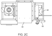
- Fig. 1 is a flow schematic of the present system, explaining its operation, as follows.
- Tire filling system 10 comprises a first mixer 20 which receives an isocyanate into an inlet 22 and a catalyst into inlet 24.
- First mixer 20 mixes the isocyanate and catalyst to form a virgin polyurethane.
- a grinder 30 grinds rubber core bits therein. These rubber core bits preferably come from pre-used tires.
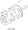
- An exemplary auger 32 ( Figs. 3A and 3B ) is disposed within grinder 30 for grinding the core bits down to a preferred small size.
- the ground core bits may have a diameter of 1/2 inch or less. This small dimension can be achieved by passing the ground rubber bits through the auger 32 and then passing through a screen having 1/2 inch holes.
- grinder 30 has an upper hopper 31 into which large pieces of rubber are inserted.
- the ground polyurethane core bits from grinder 30 and the virgin material from first mixer 20 are than mixed together in second mixer 40 to form a tire flatproofing material that is then passed through an injector 50 into a tire 60.
- Tire 60 may be either a tubed or tubeless tire.
- Injector 50 may be a screw-type injector. A pump will also accompany injector 50.
- Figs. 2A to 2D illustrate further views of the present system 10 in which a control system and method of controlling operation of tire filling mixing machine 10 is provided.
- This method first comprises: (a) mixing a polyurethane isocyanate and catalyst in first mixer 20 to form a virgin polyurethane; (b) grinding polyurethane core bits in grinder 20; (c) mixing the virgin polyurethane and the ground core bits in second mixer 40 thereby forming a mixed flatproofing material; (d) injecting the mixed flatproofing material into tire 60.
- a cured polyurethane core bit as used herein is understood to refer to herein any of a cured virgin polyurethane, a cured virgin polyurethane and a used polyurethane either in chunks or in granules, a cured virgin polyurethane blended with crumb rubber particles, or a blend of any of these.
- Figs. 3A and 3B are illustrations of an exemplary auger for use with the present system. Preferably, such measurements are taken at the opposite ends of the auger; however, additional sensor locations at the auger motor and /or gearbox are also contemplated within the scope of the present system.
- the present system operates by performing preventative maintenance on an auger in a tire filling mixing machine, by:
- the vibration is measured by an accelerometer and the temperature by a thermocouple.
- the accelerometer and thermocouple may optionally be housed together in a single sensor body.
- the present system will automatically shut down grinder 30, stopping the movement of auger 32.
- the temperature of the auger exceed its preferred maximum temperature for a predefined period of time, then the present system will automatically shut down grinder 30, stopping the movement of auger 32.
- the present inventors have experimentally determined that if the auger bearing vibration exceeds 0.14gRMS and a 160 degree Fahrenheit temperature or the discharge bearing exceeds 0.14gRMS and a temperature greater than 200 degrees Fahrenheit, or the gearbox exceeds 0.10gRMS and a 150 degree Fahrenheit temperature, a warning should be sent. Accordingly, should these conditions develop, the present system then automatically notifies technical support staff regarding the current condition.
- the present system also performs preventative maintenance on the auger by:
- the present system independently monitors the overall grinder performance based on speed, torque, and calculated temperature. As such, the present control system can automatically stop the motor prior to a damaging conditions. This independent system compliments the trending and preventative maintenance system.
- the present system may also (a) measure the level of rubber core bits in the grinder, and (b) automatically shut down the grinder and the first and second mixers if the detected level of core bits in the grinder falls below a pre-determined minimum level.
- the present system can use a combination of current ratio, weight, crumb level, and speed when determining whether to shut down the grinder.
- sensors can be added to the hopper 31 to detect the level of rubber crumb in the hopper. Should the level drop too far, the sensor(s) can be used to automatically shut down the system operation. This has the beneficial effect of preventing virgin material from being wasted when the recycled rubber crumb supply drops in the machine. Since rubber crumb is loaded into hopper 31 in bulk lots, this also ensures that the ratio of ground rubber crumb to virgin rubber material remains consistent.
Landscapes
- Engineering & Computer Science (AREA)
- Mechanical Engineering (AREA)
- Physics & Mathematics (AREA)
- General Physics & Mathematics (AREA)
- Processing And Handling Of Plastics And Other Materials For Molding In General (AREA)
Claims (5)
- Steuersystem zum Durchführen einer präventiven Wartung einer Förderschnecke in einer Reifenfüllungsmischmaschine, umfassend:(a) ein Steuersystem zum Mischen eines Polyurethanisocyanats und eines Katalysators in einem ersten Mischer, um ein natives Polyurethan zu bilden;(b) ein Steuersystem zum Mahlen von Kernbohrkronen in einer Mahlvorrichtung, wobei die Mahlvorrichtung eine Förderschnecke und einen Motor umfasst;(c) ein Steuersystem zum Mischen des reinen Polyurethans und der gemahlenen Kernbohrkronen in einer zweiten Mischvorrichtung, wodurch ein gemischtes Material gebildet wird, das platte Reifen verhindert;(d) ein Steuersystem zum Einspritzen des gemischten Materials, das platte Reifen verhindert, in einen Reifen; und(e) ein Steuersystem zum Messen der Schwingung der Förderschnecke;dadurch gekennzeichnet, dass:(f) ein Schwingungsmesssystem zum Vergleichen der gemessenen Schwingung der Förderschnecke mit einer vordefinierten maximalen Schwingung; und(g) ein Warnsystem zum Benachrichtigen eines Bedieners, die Förderschnecke aus der Mahlvorrichtung zu entfernen, wenn die gemessene Schwingung die vordefinierte maximale Schwingung für einen vordefinierten Zeitraum überschreitet.
- Steuersystem nach Anspruch 1, das weiters Folgendes umfasst:(h) ein Temperaturmesssystem zum Messen der Temperatur der Förderschnecke und Vergleichen der gemessenen Temperatur der Förderschnecke mit einer vordefinierten maximalen Temperatur; und(i) ein Warnsystem zum Benachrichtigen eines Bedieners, die Förderschnecke aus der Mahlvorrichtung zu entfernen, wenn die gemessene Temperatur die vordefinierte maximale Temperatur der Förderschnecke für einen vordefinierten Zeitraum überschreitet.
- Steuersystem nach Anspruch 1, wobei die Schwingung und die Temperatur der Förderschnecke mit Sensoren gemessen werden, die auf Förderschneckenlagern und auf dem Mahlvorrichtungsmotor angeordnet sind.
- Steuersystem nach Anspruch 1, das weiters Folgendes umfasst:(h) ein Messsystem zum Messen der Leistung des Motors in der Mahlvorrichtung, wobei das Messen der Leistung des Motors das Messen von zumindest einem der Folgenden umfasst:der Stromstärke des Motors,der Drehzahl des Motors,der Schwingung des Motors,der Temperatur des Motors,eines Magnetfelds des Motors undGeräuschen, die der Motor erzeugt; und(i) ein Warnsystem zum Benachrichtigen eines Bedieners, den Motor zu stoppen, wenn die gemessene Leistung des Motors für einen vordefinierten Zeitraum außerhalb eines vordefinierten Leistungsbereichs bleibt.
- Steuersystem nach Anspruch 1, das weiters Folgendes umfasst:(h) ein Messsystem zum Messen des Pegels von Kernbohrkronen in der Mahlvorrichtung und(i) ein Steuersystem zum automatischen Abschalten der Mahlvorrichtung und des ersten und des zweiten Mischers, falls der detektierte Pegel von Kernbohrkronen in der Mahlvorrichtung unter einen vorbestimmten minimalen Pegel fällt.
Priority Applications (1)
| Application Number | Priority Date | Filing Date | Title |
|---|---|---|---|
| EP24223767.5A EP4574407A1 (de) | 2019-09-12 | 2020-08-11 | System zur vorhersage von schneckenfehlern in einer reifeneinspritzfüllmischmaschine |
Applications Claiming Priority (3)
| Application Number | Priority Date | Filing Date | Title |
|---|---|---|---|
| US201962899466P | 2019-09-12 | 2019-09-12 | |
| PCT/US2020/045789 WO2021050188A1 (en) | 2019-09-12 | 2020-08-11 | System for predicting auger failure in a tire injection filling mxing machine |
| EP20863234.9A EP3972823B1 (de) | 2019-09-12 | 2020-08-11 | System zur vorhersage des ausfalls einer schnecke in einer reifeninjektionsfüllmischmaschine |
Related Parent Applications (2)
| Application Number | Title | Priority Date | Filing Date |
|---|---|---|---|
| EP20863234.9A Division EP3972823B1 (de) | 2019-09-12 | 2020-08-11 | System zur vorhersage des ausfalls einer schnecke in einer reifeninjektionsfüllmischmaschine |
| EP20863234.9A Division-Into EP3972823B1 (de) | 2019-09-12 | 2020-08-11 | System zur vorhersage des ausfalls einer schnecke in einer reifeninjektionsfüllmischmaschine |
Related Child Applications (2)
| Application Number | Title | Priority Date | Filing Date |
|---|---|---|---|
| EP24223767.5A Division EP4574407A1 (de) | 2019-09-12 | 2020-08-11 | System zur vorhersage von schneckenfehlern in einer reifeneinspritzfüllmischmaschine |
| EP24223767.5A Division-Into EP4574407A1 (de) | 2019-09-12 | 2020-08-11 | System zur vorhersage von schneckenfehlern in einer reifeneinspritzfüllmischmaschine |
Publications (3)
| Publication Number | Publication Date |
|---|---|
| EP4227074A1 EP4227074A1 (de) | 2023-08-16 |
| EP4227074B1 true EP4227074B1 (de) | 2025-05-21 |
| EP4227074C0 EP4227074C0 (de) | 2025-05-21 |
Family
ID=74260984
Family Applications (3)
| Application Number | Title | Priority Date | Filing Date |
|---|---|---|---|
| EP23163955.0A Active EP4227074B1 (de) | 2019-09-12 | 2020-08-11 | System zur vorhersage des ausfalls einer schnecke in einer reifeninjektionsfüllmischmaschine |
| EP24223767.5A Pending EP4574407A1 (de) | 2019-09-12 | 2020-08-11 | System zur vorhersage von schneckenfehlern in einer reifeneinspritzfüllmischmaschine |
| EP20863234.9A Active EP3972823B1 (de) | 2019-09-12 | 2020-08-11 | System zur vorhersage des ausfalls einer schnecke in einer reifeninjektionsfüllmischmaschine |
Family Applications After (2)
| Application Number | Title | Priority Date | Filing Date |
|---|---|---|---|
| EP24223767.5A Pending EP4574407A1 (de) | 2019-09-12 | 2020-08-11 | System zur vorhersage von schneckenfehlern in einer reifeneinspritzfüllmischmaschine |
| EP20863234.9A Active EP3972823B1 (de) | 2019-09-12 | 2020-08-11 | System zur vorhersage des ausfalls einer schnecke in einer reifeninjektionsfüllmischmaschine |
Country Status (6)
| Country | Link |
|---|---|
| US (2) | US10906260B1 (de) |
| EP (3) | EP4227074B1 (de) |
| CN (1) | CN114555345A (de) |
| CA (1) | CA3150977C (de) |
| WO (1) | WO2021050188A1 (de) |
| ZA (1) | ZA202202989B (de) |
Families Citing this family (2)
| Publication number | Priority date | Publication date | Assignee | Title |
|---|---|---|---|---|
| US10346378B1 (en) | 2018-11-30 | 2019-07-09 | Slack Technologies, Inc. | Data storage architecture for an enterprise communication system |
| ES2942084B2 (es) * | 2021-11-29 | 2024-05-03 | Valora Teruel S L | Producto de relleno de neumaticos con caucho micronizado |
Family Cites Families (12)
| Publication number | Priority date | Publication date | Assignee | Title |
|---|---|---|---|---|
| US5238734A (en) * | 1990-02-13 | 1993-08-24 | Murray Kevin N | Railroad ties made of recycled tire fragments |
| US6187125B1 (en) * | 1997-09-05 | 2001-02-13 | Arnco | Method for producing a deflation-proof pneumatic tire and tire filling composition having high resilience |
| US6918979B2 (en) * | 2000-08-16 | 2005-07-19 | Pc Industries | Method for making tires filled with flatproofing material |
| US6988524B2 (en) * | 2000-08-16 | 2006-01-24 | Pc Industries | Apparatus for making tires filled with flatproofing material |
| US8186991B2 (en) * | 2004-02-27 | 2012-05-29 | Jmp Industries, Inc. | Extruder system and cutting assembly |
| US7043178B1 (en) | 2004-12-14 | 2006-05-09 | Xerox Corporation | Noise damper for wire auger |
| US9855682B2 (en) * | 2011-06-10 | 2018-01-02 | Columbia Insurance Company | Methods of recycling synthetic turf, methods of using reclaimed synthetic turf, and products comprising same |
| CA3157420A1 (en) * | 2011-10-21 | 2013-04-25 | Prime Datum, Inc. | Direct drive fan system with variable process control |
| EP2911850A4 (de) * | 2012-10-24 | 2016-06-22 | Phoenix Innovation Technology Inc | Temperaturgesteuerter thermokinetischer mixer |
| CN103217645B (zh) * | 2013-04-07 | 2015-12-02 | 上海申瑞继保电气有限公司 | 风电场的风机隐性故障监测方法 |
| US20150217525A1 (en) | 2014-02-04 | 2015-08-06 | Dash Multi-Corp, Inc. | Recycled rubber particles, products comprising the same, and methods of using and producing the products |
| US10451008B2 (en) * | 2016-07-29 | 2019-10-22 | Precision Compression, LLC | Compression system |
-
2020
- 2020-08-11 WO PCT/US2020/045789 patent/WO2021050188A1/en not_active Ceased
- 2020-08-11 CA CA3150977A patent/CA3150977C/en active Active
- 2020-08-11 EP EP23163955.0A patent/EP4227074B1/de active Active
- 2020-08-11 US US16/990,785 patent/US10906260B1/en active Active
- 2020-08-11 EP EP24223767.5A patent/EP4574407A1/de active Pending
- 2020-08-11 CN CN202080070262.9A patent/CN114555345A/zh active Pending
- 2020-08-11 EP EP20863234.9A patent/EP3972823B1/de active Active
- 2020-12-23 US US17/132,853 patent/US10953616B1/en active Active
-
2022
- 2022-03-11 ZA ZA2022/02989A patent/ZA202202989B/en unknown
Also Published As
| Publication number | Publication date |
|---|---|
| US10953616B1 (en) | 2021-03-23 |
| CA3150977A1 (en) | 2021-03-18 |
| EP4574407A1 (de) | 2025-06-25 |
| EP3972823A4 (de) | 2022-08-31 |
| EP3972823C0 (de) | 2023-06-07 |
| CA3150977C (en) | 2022-11-08 |
| EP3972823B1 (de) | 2023-06-07 |
| EP4227074A1 (de) | 2023-08-16 |
| EP3972823A1 (de) | 2022-03-30 |
| US10906260B1 (en) | 2021-02-02 |
| ZA202202989B (en) | 2023-02-22 |
| WO2021050188A1 (en) | 2021-03-18 |
| CN114555345A (zh) | 2022-05-27 |
| EP4227074C0 (de) | 2025-05-21 |
Similar Documents
| Publication | Publication Date | Title |
|---|---|---|
| EP4227074B1 (de) | System zur vorhersage des ausfalls einer schnecke in einer reifeninjektionsfüllmischmaschine | |
| US8096698B2 (en) | Load monitoring method and load monitoring apparatus for kneading apparatus | |
| CN1043444C (zh) | 开口容器内流动性混合物料料位调节法 | |
| JP2013531568A (ja) | プラスチックの加工方法および装置 | |
| CN113825611B (zh) | 用于填充状态的方法及设备和注射成型机/挤出机单元 | |
| CN101594940B (zh) | 用于立式研磨机的控制方法和控制器 | |
| KR101207623B1 (ko) | 소결 쿨러 팬 제어 장치 및 이를 이용한 소결 쿨러 팬 제어 방법 | |
| JP7326397B2 (ja) | ローラミル用の分配計量供給装置、このような分配計量供給装置を有するローラミル、粉砕原料を粉砕するための方法、および冷却システムを有する配電盤キャビネットを備えたローラミル | |
| KR101796747B1 (ko) | 원료 정량 공급 장치 및 공급 방법 | |
| JP4919159B2 (ja) | 竪型粉砕機の制御方法及び制御装置 | |
| JP5057214B2 (ja) | 竪型粉砕機の制御方法 | |
| JP2005029170A (ja) | 細片排出装置 | |
| JP7306256B2 (ja) | 竪型粉砕機用ローラタイヤの監視システム及び監視方法 | |
| CA3150931A1 (en) | Control system for tire injection filling mixing machine | |
| US20170205209A1 (en) | Projectile collection system | |
| JP2000288504A (ja) | 固形物成形機の制御方法 | |
| WO2016053117A1 (en) | Improvements in and relating to automated produce processing machines | |
| US5045252A (en) | Method and apparatus for controlling rotary extruder | |
| JP4133257B2 (ja) | 廃プラスチックの造粒方法および造粒装置 | |
| JP2003038980A (ja) | 土質改良装置用破砕混合機の制御装置 | |
| JP3850780B2 (ja) | 加工物供給異常検出方法及び加工物供給異常検出装置 | |
| JP4978835B2 (ja) | 竪型粉砕機の制御方法 | |
| KR101694440B1 (ko) | 드럼피더에 부착된 소결광의 제거 장치 및 방법 | |
| Smith | Making the right choice | |
| JPH06320030A (ja) | 竪型粉砕機 |
Legal Events
| Date | Code | Title | Description |
|---|---|---|---|
| PUAI | Public reference made under article 153(3) epc to a published international application that has entered the european phase |
Free format text: ORIGINAL CODE: 0009012 |
|
| STAA | Information on the status of an ep patent application or granted ep patent |
Free format text: STATUS: THE APPLICATION HAS BEEN PUBLISHED |
|
| AC | Divisional application: reference to earlier application |
Ref document number: 3972823 Country of ref document: EP Kind code of ref document: P |
|
| AK | Designated contracting states |
Kind code of ref document: A1 Designated state(s): AL AT BE BG CH CY CZ DE DK EE ES FI FR GB GR HR HU IE IS IT LI LT LU LV MC MK MT NL NO PL PT RO RS SE SI SK SM TR |
|
| STAA | Information on the status of an ep patent application or granted ep patent |
Free format text: STATUS: REQUEST FOR EXAMINATION WAS MADE |
|
| 17P | Request for examination filed |
Effective date: 20240215 |
|
| RBV | Designated contracting states (corrected) |
Designated state(s): AL AT BE BG CH CY CZ DE DK EE ES FI FR GB GR HR HU IE IS IT LI LT LU LV MC MK MT NL NO PL PT RO RS SE SI SK SM TR |
|
| GRAP | Despatch of communication of intention to grant a patent |
Free format text: ORIGINAL CODE: EPIDOSNIGR1 |
|
| STAA | Information on the status of an ep patent application or granted ep patent |
Free format text: STATUS: GRANT OF PATENT IS INTENDED |
|
| RIC1 | Information provided on ipc code assigned before grant |
Ipc: B29B 7/74 20060101ALN20240701BHEP Ipc: B29B 7/24 20060101ALN20240701BHEP Ipc: B29B 7/28 20060101ALN20240701BHEP Ipc: B29B 7/16 20060101ALN20240701BHEP Ipc: B29B 7/14 20060101ALN20240701BHEP Ipc: B29B 9/02 20060101ALI20240701BHEP Ipc: B29B 9/04 20060101ALI20240701BHEP Ipc: B60C 7/10 20060101ALI20240701BHEP Ipc: B60C 7/00 20060101ALI20240701BHEP Ipc: B29D 30/04 20060101AFI20240701BHEP |
|
| INTG | Intention to grant announced |
Effective date: 20240712 |
|
| GRAJ | Information related to disapproval of communication of intention to grant by the applicant or resumption of examination proceedings by the epo deleted |
Free format text: ORIGINAL CODE: EPIDOSDIGR1 |
|
| STAA | Information on the status of an ep patent application or granted ep patent |
Free format text: STATUS: REQUEST FOR EXAMINATION WAS MADE |
|
| INTC | Intention to grant announced (deleted) | ||
| GRAP | Despatch of communication of intention to grant a patent |
Free format text: ORIGINAL CODE: EPIDOSNIGR1 |
|
| STAA | Information on the status of an ep patent application or granted ep patent |
Free format text: STATUS: GRANT OF PATENT IS INTENDED |
|
| RIC1 | Information provided on ipc code assigned before grant |
Ipc: B29B 7/74 20060101ALN20241127BHEP Ipc: B29B 7/24 20060101ALN20241127BHEP Ipc: B29B 7/28 20060101ALN20241127BHEP Ipc: B29B 7/16 20060101ALN20241127BHEP Ipc: B29B 7/14 20060101ALN20241127BHEP Ipc: B29B 9/02 20060101ALI20241127BHEP Ipc: B29B 9/04 20060101ALI20241127BHEP Ipc: B60C 7/10 20060101ALI20241127BHEP Ipc: B60C 7/00 20060101ALI20241127BHEP Ipc: B29D 30/04 20060101AFI20241127BHEP |
|
| INTG | Intention to grant announced |
Effective date: 20241212 |
|
| GRAS | Grant fee paid |
Free format text: ORIGINAL CODE: EPIDOSNIGR3 |
|
| GRAA | (expected) grant |
Free format text: ORIGINAL CODE: 0009210 |
|
| STAA | Information on the status of an ep patent application or granted ep patent |
Free format text: STATUS: THE PATENT HAS BEEN GRANTED |
|
| AC | Divisional application: reference to earlier application |
Ref document number: 3972823 Country of ref document: EP Kind code of ref document: P |
|
| AK | Designated contracting states |
Kind code of ref document: B1 Designated state(s): AL AT BE BG CH CY CZ DE DK EE ES FI FR GB GR HR HU IE IS IT LI LT LU LV MC MK MT NL NO PL PT RO RS SE SI SK SM TR |
|
| REG | Reference to a national code |
Ref country code: GB Ref legal event code: FG4D |
|
| REG | Reference to a national code |
Ref country code: CH Ref legal event code: EP |
|
| REG | Reference to a national code |
Ref country code: DE Ref legal event code: R096 Ref document number: 602020051921 Country of ref document: DE |
|
| REG | Reference to a national code |
Ref country code: IE Ref legal event code: FG4D |
|
| U01 | Request for unitary effect filed |
Effective date: 20250522 |
|
| U07 | Unitary effect registered |
Designated state(s): AT BE BG DE DK EE FI FR IT LT LU LV MT NL PT RO SE SI Effective date: 20250602 |
|
| U20 | Renewal fee for the european patent with unitary effect paid |
Year of fee payment: 6 Effective date: 20250827 |
|
| PG25 | Lapsed in a contracting state [announced via postgrant information from national office to epo] |
Ref country code: ES Free format text: LAPSE BECAUSE OF FAILURE TO SUBMIT A TRANSLATION OF THE DESCRIPTION OR TO PAY THE FEE WITHIN THE PRESCRIBED TIME-LIMIT Effective date: 20250521 |
|
| PG25 | Lapsed in a contracting state [announced via postgrant information from national office to epo] |
Ref country code: NO Free format text: LAPSE BECAUSE OF FAILURE TO SUBMIT A TRANSLATION OF THE DESCRIPTION OR TO PAY THE FEE WITHIN THE PRESCRIBED TIME-LIMIT Effective date: 20250821 Ref country code: GR Free format text: LAPSE BECAUSE OF FAILURE TO SUBMIT A TRANSLATION OF THE DESCRIPTION OR TO PAY THE FEE WITHIN THE PRESCRIBED TIME-LIMIT Effective date: 20250822 |
|
| PG25 | Lapsed in a contracting state [announced via postgrant information from national office to epo] |
Ref country code: PL Free format text: LAPSE BECAUSE OF FAILURE TO SUBMIT A TRANSLATION OF THE DESCRIPTION OR TO PAY THE FEE WITHIN THE PRESCRIBED TIME-LIMIT Effective date: 20250521 |
|
| PGFP | Annual fee paid to national office [announced via postgrant information from national office to epo] |
Ref country code: GB Payment date: 20250827 Year of fee payment: 6 |
|
| PG25 | Lapsed in a contracting state [announced via postgrant information from national office to epo] |
Ref country code: HR Free format text: LAPSE BECAUSE OF FAILURE TO SUBMIT A TRANSLATION OF THE DESCRIPTION OR TO PAY THE FEE WITHIN THE PRESCRIBED TIME-LIMIT Effective date: 20250521 |
|
| PG25 | Lapsed in a contracting state [announced via postgrant information from national office to epo] |
Ref country code: RS Free format text: LAPSE BECAUSE OF FAILURE TO SUBMIT A TRANSLATION OF THE DESCRIPTION OR TO PAY THE FEE WITHIN THE PRESCRIBED TIME-LIMIT Effective date: 20250821 |
|
| PG25 | Lapsed in a contracting state [announced via postgrant information from national office to epo] |
Ref country code: IS Free format text: LAPSE BECAUSE OF FAILURE TO SUBMIT A TRANSLATION OF THE DESCRIPTION OR TO PAY THE FEE WITHIN THE PRESCRIBED TIME-LIMIT Effective date: 20250921 |
|
| PG25 | Lapsed in a contracting state [announced via postgrant information from national office to epo] |
Ref country code: SM Free format text: LAPSE BECAUSE OF FAILURE TO SUBMIT A TRANSLATION OF THE DESCRIPTION OR TO PAY THE FEE WITHIN THE PRESCRIBED TIME-LIMIT Effective date: 20250521 |
|
| PG25 | Lapsed in a contracting state [announced via postgrant information from national office to epo] |
Ref country code: CZ Free format text: LAPSE BECAUSE OF FAILURE TO SUBMIT A TRANSLATION OF THE DESCRIPTION OR TO PAY THE FEE WITHIN THE PRESCRIBED TIME-LIMIT Effective date: 20250521 |
|
| PG25 | Lapsed in a contracting state [announced via postgrant information from national office to epo] |
Ref country code: SK Free format text: LAPSE BECAUSE OF FAILURE TO SUBMIT A TRANSLATION OF THE DESCRIPTION OR TO PAY THE FEE WITHIN THE PRESCRIBED TIME-LIMIT Effective date: 20250521 |
|
| REG | Reference to a national code |
Ref country code: CH Ref legal event code: H13 Free format text: ST27 STATUS EVENT CODE: U-0-0-H10-H13 (AS PROVIDED BY THE NATIONAL OFFICE) Effective date: 20260324 |
|
| PLBE | No opposition filed within time limit |
Free format text: ORIGINAL CODE: 0009261 |
|
| STAA | Information on the status of an ep patent application or granted ep patent |
Free format text: STATUS: NO OPPOSITION FILED WITHIN TIME LIMIT |
|
| PG25 | Lapsed in a contracting state [announced via postgrant information from national office to epo] |
Ref country code: MC Free format text: LAPSE BECAUSE OF FAILURE TO SUBMIT A TRANSLATION OF THE DESCRIPTION OR TO PAY THE FEE WITHIN THE PRESCRIBED TIME-LIMIT Effective date: 20250521 |
|
| REG | Reference to a national code |
Ref country code: CH Ref legal event code: L10 Free format text: ST27 STATUS EVENT CODE: U-0-0-L10-L00 (AS PROVIDED BY THE NATIONAL OFFICE) Effective date: 20260402 |