EP4224176B1 - Testsystem und verfahren für eine leistungsumwandlungsvorrichtung sowie elektronische vorrichtung und speichermedium - Google Patents
Testsystem und verfahren für eine leistungsumwandlungsvorrichtung sowie elektronische vorrichtung und speichermedium Download PDFInfo
- Publication number
- EP4224176B1 EP4224176B1 EP22851767.8A EP22851767A EP4224176B1 EP 4224176 B1 EP4224176 B1 EP 4224176B1 EP 22851767 A EP22851767 A EP 22851767A EP 4224176 B1 EP4224176 B1 EP 4224176B1
- Authority
- EP
- European Patent Office
- Prior art keywords
- power conversion
- conversion device
- charge
- discharge
- working mode
- Prior art date
- Legal status (The legal status is an assumption and is not a legal conclusion. Google has not performed a legal analysis and makes no representation as to the accuracy of the status listed.)
- Active
Links
Images


Classifications
-
- H—ELECTRICITY
- H02—GENERATION; CONVERSION OR DISTRIBUTION OF ELECTRIC POWER
- H02M—APPARATUS FOR CONVERSION BETWEEN AC AND AC, BETWEEN AC AND DC, OR BETWEEN DC AND DC, AND FOR USE WITH MAINS OR SIMILAR POWER SUPPLY SYSTEMS; CONVERSION OF DC OR AC INPUT POWER INTO SURGE OUTPUT POWER; CONTROL OR REGULATION THEREOF
- H02M5/00—Conversion of AC power input into AC power output, e.g. for change of voltage, for change of frequency, for change of number of phases
- H02M5/40—Conversion of AC power input into AC power output, e.g. for change of voltage, for change of frequency, for change of number of phases with intermediate conversion into DC
- H02M5/42—Conversion of AC power input into AC power output, e.g. for change of voltage, for change of frequency, for change of number of phases with intermediate conversion into DC by static converters
- H02M5/44—Conversion of AC power input into AC power output, e.g. for change of voltage, for change of frequency, for change of number of phases with intermediate conversion into DC by static converters using discharge tubes or semiconductor devices to convert the intermediate DC into AC
- H02M5/453—Conversion of AC power input into AC power output, e.g. for change of voltage, for change of frequency, for change of number of phases with intermediate conversion into DC by static converters using discharge tubes or semiconductor devices to convert the intermediate DC into AC using devices of a triode or transistor type requiring continuous application of a control signal
- H02M5/458—Conversion of AC power input into AC power output, e.g. for change of voltage, for change of frequency, for change of number of phases with intermediate conversion into DC by static converters using discharge tubes or semiconductor devices to convert the intermediate DC into AC using devices of a triode or transistor type requiring continuous application of a control signal using semiconductor devices only
-
- G—PHYSICS
- G01—MEASURING; TESTING
- G01R—MEASURING ELECTRIC VARIABLES; MEASURING MAGNETIC VARIABLES
- G01R31/00—Arrangements for testing electric properties; Arrangements for locating electric faults; Arrangements for electrical testing characterised by what is being tested not provided for elsewhere
- G01R31/36—Arrangements for testing, measuring or monitoring the electrical condition of accumulators or electric batteries, e.g. capacity or state of charge [SoC]
- G01R31/392—Determining battery ageing or deterioration, e.g. state of health
-
- G—PHYSICS
- G01—MEASURING; TESTING
- G01R—MEASURING ELECTRIC VARIABLES; MEASURING MAGNETIC VARIABLES
- G01R31/00—Arrangements for testing electric properties; Arrangements for locating electric faults; Arrangements for electrical testing characterised by what is being tested not provided for elsewhere
- G01R31/40—Testing power supplies
- G01R31/42—AC power supplies
-
- H—ELECTRICITY
- H02—GENERATION; CONVERSION OR DISTRIBUTION OF ELECTRIC POWER
- H02M—APPARATUS FOR CONVERSION BETWEEN AC AND AC, BETWEEN AC AND DC, OR BETWEEN DC AND DC, AND FOR USE WITH MAINS OR SIMILAR POWER SUPPLY SYSTEMS; CONVERSION OF DC OR AC INPUT POWER INTO SURGE OUTPUT POWER; CONTROL OR REGULATION THEREOF
- H02M1/00—Details of apparatus for conversion
- H02M1/0067—Converter structures employing plural converter units, other than for parallel operation of the units on a single load
-
- H—ELECTRICITY
- H02—GENERATION; CONVERSION OR DISTRIBUTION OF ELECTRIC POWER
- H02M—APPARATUS FOR CONVERSION BETWEEN AC AND AC, BETWEEN AC AND DC, OR BETWEEN DC AND DC, AND FOR USE WITH MAINS OR SIMILAR POWER SUPPLY SYSTEMS; CONVERSION OF DC OR AC INPUT POWER INTO SURGE OUTPUT POWER; CONTROL OR REGULATION THEREOF
- H02M5/00—Conversion of AC power input into AC power output, e.g. for change of voltage, for change of frequency, for change of number of phases
- H02M5/40—Conversion of AC power input into AC power output, e.g. for change of voltage, for change of frequency, for change of number of phases with intermediate conversion into DC
-
- H—ELECTRICITY
- H02—GENERATION; CONVERSION OR DISTRIBUTION OF ELECTRIC POWER
- H02M—APPARATUS FOR CONVERSION BETWEEN AC AND AC, BETWEEN AC AND DC, OR BETWEEN DC AND DC, AND FOR USE WITH MAINS OR SIMILAR POWER SUPPLY SYSTEMS; CONVERSION OF DC OR AC INPUT POWER INTO SURGE OUTPUT POWER; CONTROL OR REGULATION THEREOF
- H02M1/00—Details of apparatus for conversion
- H02M1/32—Means for protecting converters other than automatic disconnection
-
- H—ELECTRICITY
- H02—GENERATION; CONVERSION OR DISTRIBUTION OF ELECTRIC POWER
- H02M—APPARATUS FOR CONVERSION BETWEEN AC AND AC, BETWEEN AC AND DC, OR BETWEEN DC AND DC, AND FOR USE WITH MAINS OR SIMILAR POWER SUPPLY SYSTEMS; CONVERSION OF DC OR AC INPUT POWER INTO SURGE OUTPUT POWER; CONTROL OR REGULATION THEREOF
- H02M7/00—Conversion of AC power input into DC power output; Conversion of DC power input into AC power output
- H02M7/42—Conversion of DC power input into AC power output without possibility of reversal
- H02M7/44—Conversion of DC power input into AC power output without possibility of reversal by static converters
Definitions
- the embodiments of the present application relate to the technical field of aging test, and in particular, to a test system and method for power conversion devices, an electronic device, and a storage medium.
- the power conversion device refers to a bidirectional AC (alternating current)/DC (direct current), which can convert an AC power from the grid into a DC power and output it to and charge the battery of an electric vehicle, and can also convert a DC power of an electric vehicle into an AC power and feed it back to the grid.
- the power conversion device In order to ensure the reliability of the power conversion device and avoid early failure caused by the defects of the material itself, the power conversion device needs to be subjected to 100% aging test.
- a DC power supply and a load need to be provided for power conversion devices to be aged. If a large number of power conversion devices are aged at the same time, a large number of DC power supplies need to be used, causing large investment cost and energy consumption.
- embodiments of the present application provide a test system for power conversion devices according to claim 1, a method according to claim 3, an electronic device according to claim 12, and a storage medium according to claim 11, which have low test investment cost and low energy consumption.
- a test system for power conversion devices includes: a first AC input/output section, configured to connect a power supply grid and an AC terminal of a first power conversion device; a second AC input and output section, configured to connect the power supply grid and an AC terminal of a second power conversion device, where a DC terminal of the first power conversion device is connected to a DC terminal of the second power conversion device; a control unit, configured to control the first power conversion device and the second power conversion device to work simultaneously in different working modes; and an evaluation unit, configured to obtain test data when the first power conversion device and the second power conversion device work in different working modes, and evaluate the first power conversion device and the second power conversion device according to the test data.
- the first power conversion device and the second power conversion device are paired, which can both act as a load and a power source. That is, one power conversion device to be tested can be used as a power supply and load for the other power conversion device to be tested. Therefore, no additional DC power supply and load are required during the test, thus saving the investment cost and conserving electricity because the system itself consumes less energy.
- the first power conversion device and the second power conversion device work simultaneously in different working modes in the same test loop, so the aging test can be performed on the first power conversion device and the second power conversion device at the same time, which improves the test efficiency. Furthermore, since no additional DC power supply is required in the test system, the device occupies less space, and the stability of the test system is not affected.
- the working modes include a first working mode and a second working mode.
- the first power conversion device works in the first working mode, and the second power conversion device works in the second working mode; or, the first power conversion device works in the second working mode, and the second power conversion device works in the first working mode.
- the first power conversion device and the second power conversion device work simultaneously in different working modes in the same test loop, so the aging test can be performed on the first power conversion device and the second power conversion device at the same time, which improves the test efficiency.
- control unit includes: a relay control board and a plurality of relays, where the plurality of relays are arranged on the relay control board.
- the first power conversion device and the second power conversion device are respectively connected to different relays, and the relays are configured to switch the communication of the first power conversion device and the second power conversion device.
- the first power conversion device and the second power conversion device are respectively connected to different relays, the communication state between the first power conversion device and the control unit and the communication state between the second power conversion device and the control unit are changed through the relays.
- the communication state is relatively simple to control, which improves the test efficiency of the power conversion device.
- a test method for power conversion devices includes: connecting a power supply grid respectively to an AC terminal of a first power conversion device and an AC terminal of a second power conversion device; connecting a DC terminal of the first power conversion device to a DC terminal of the second power conversion device; controlling the first power conversion device and the second power conversion device to work simultaneously in different working modes; and obtaining test data when the first power conversion device and the second power conversion device work in different working modes, and evaluating the first power conversion device and the second power conversion device according to the test data.
- a test loop can be formed by the power supply grid, the first power conversion device and the second power conversion device.
- the grid, the first power conversion device and the second power conversion device can act as a load and a power source, so no additional DC power supply and load are required during the test, thus saving the investment cost and energy consumption.
- the first power conversion device and the second power conversion device work simultaneously in different working modes, so the test can be performed on the first power conversion device and the second power conversion device at the same time, which improves the test efficiency.
- the working modes include a first working mode and a second working mode.
- the first power conversion device works in the first working mode, and the second power conversion device works in the second working mode; or, the first power conversion device works in the second working mode, and the second power conversion device works in the first working mode.
- the first power conversion device and the second power conversion device work simultaneously in different working modes in the same test loop, so the aging test can be performed on the first power conversion device and the second power conversion device at the same time, which improves the test efficiency.
- control unit includes: a relay control board and a plurality of relays, where the plurality of relays are arranged on the relay control board.
- the first power conversion device and the second power conversion device are respectively connected to different relays, and the relays are configured to switch the communication of the first power conversion device and the second power conversion device.
- the first power conversion device and the second power conversion device are respectively connected to different relays, the communication state between the first power conversion device and the control unit and the communication state between the second power conversion device and the control unit are changed through the relays.
- the communication state is relatively simple to control, which improves the test efficiency of the power conversion device.
- the controlling the first power conversion device and the second power conversion device to work simultaneously in different working modes includes: controlling the first power conversion device to undergo a first stage of charge and discharge in the first working mode, and controlling the second power conversion device to undergo a first stage of charge and discharge in the second working mode; and when the first stage of charge and discharge ends, controlling the first power conversion device to undergo a second stage of charge and discharge in the second work mode, and controlling the second power conversion device to undergo a second stage of charge and discharge in the first working mode.
- control unit controls the first power conversion device and the second power conversion device to work simultaneously in different working modes, so the aging test can be performed on the first power conversion device and the second power conversion device at the same time, which improves the test efficiency.
- controlling the first power conversion device to undergo a first stage of charge and discharge in the first working mode and controlling the second power conversion device to undergo a first stage of charge and discharge in the second working mode include: controlling a first relay corresponding to the first power conversion device to close and sending a first turn-on instruction to the first power conversion device, so that the first power conversion device undergoes the first stage of charge and discharge in the first working mode; and controlling the first relay to open, controlling a second relay corresponding to the second power conversion device to close, and sending a second turn-on instruction to the second power conversion device, so that the second power conversion device undergoes the first stage of charge and discharge in the second working mode.
- the first power conversion device and the second power conversion device can act as a load and a power source, so no additional DC power supply and load are required during the test, thus saving the investment cost and energy consumption.
- the first power conversion device and the second power conversion device work simultaneously, so the aging test can be performed on the first power conversion device and the second power conversion device at the same time, which improves the test performance. efficiency.
- an embodiment means that a particular feature, structure, or characteristic described in connection with the embodiment can be included in at least one embodiment of the present application.
- the appearance of this phrase anywhere in the specification does not necessarily refer to the same embodiment, or a separate or alternative embodiment that is mutually exclusive with other embodiments. It is explicitly and implicitly understood by those skilled in the art that the embodiments described herein may be combined with other embodiments.
- a plurality of refers to two or more (including two), and similarly, “multiple groups” refers to two or more (including two) groups, and “multiple sheets” refers to two or more (including two) sheets.
- the technical terms “mount,” “join,” “connect,” and “fix,” etc. should be understood in a broad sense, such as, a fixed connection, a detachable connection, or an integral connection; a mechanical connection, or an electrical connection; a direct connection, an indirect connection through an intermediate medium, an internal connection of two elements, or interaction between two elements.
- the specific meanings of the above terms in the embodiments of the present application can be understood according to specific situations.
- a DC terminal of the power conversion device is often connected to one terminal of a DC power supply, and an AC terminal of the power conversion device and the other terminal of the DC power supply are both connected to a grid to form a test loop.
- the DC terminal of the power conversion device refers to the DC side of the power conversion device in FIG. 1
- the DC power supply refers to the DC source in FIG. 1
- the AC terminal of the power conversion device refers to the AC side of the power conversion device in FIG. 1 .
- a control unit 00 controls each power conversion device to work in different working modes, so as to perform an aging test on the power conversion device.
- FIG. 1 shows a plurality of power conversion devices, which are marked as product 1, product 2, product 3,..., product N in sequence in FIG. 1 .
- an embodiment of the present application provides a test system for power conversion devices.
- a power supply grid is connected to an AC terminal of a first power conversion device, the power supply grid is also connected to an AC terminal of a second power conversion device, and a DC terminal of the first power conversion device is connected to a DC terminal of the second power conversion device.
- a test loop is formed by the power supply grid, the first power conversion device and the second power conversion device.
- a control unit 3 can control the first power conversion device and the second power conversion device to work simultaneously in different working modes
- an evaluation unit 4 can obtain the test data of the first power conversion device and the second power conversion device when they work in different working modes, and evaluate the first power conversion device and the second power conversion device according to the test data.
- the first power conversion device and the second power conversion device are paired, which can both act as a load and a power source. That is, one power conversion device to be tested can be used as a power supply and load for the other power conversion device to be tested. Therefore, no additional DC power supply and load are required during the test, thus saving the investment cost and conserving electricity because the system itself consumes less energy.
- the first power conversion device and the second power conversion device work simultaneously in different working modes in the same test loop, so the aging test can be performed on the first power conversion device and the second power conversion device at the same time, which improves the test efficiency. Furthermore, since no additional DC power supply is required in the test system, the device occupies less space, and the stability of the test system is not affected.
- a DC terminal of the first power conversion device is connected to a DC terminal of the second power conversion device.
- the control unit 3 is configured to control the first power conversion device and the second power conversion device to work simultaneously in different working modes.
- the evaluation unit 4 is configured to obtain the test data of the first power conversion device and the second power conversion device when they work in different working modes, and evaluate the first power conversion device and the second power conversion device according to the test data.
- the first power conversion device and the second power conversion device are bidirectional AC/DC conversion devices. On the one hand, they can act as a load to receive an AC power and convert the received AC power into a DC power, and then act as a power source to output the DC power. On the other hand, they can act as a load to receive a DC power and convert the received DC power into an AC power, and then act as a power source to output the AC power. That is to say, the first power conversion device and the second power conversion device can act as a load and a power source, and can not only receive the AC power and output the DC power, but also receive the DC power and output the AC power.
- first AC input/output section 1 and the second AC input/output section 2 may be an AC input/output interface.
- the power supply grid is connected to the AC terminal of the first power conversion device through the first AC input/output section 1, the power supply grid is connected to the AC terminal of the second power conversion device through the second AC input/output section 2, and then the DC terminal of the first power conversion device is connected to the DC terminal of the second power conversion device.
- a test loop is formed by the power supply grid, the first power conversion device and the second power conversion device.
- the DC terminal of the first power conversion device is connected to the DC terminal of the second power conversion device, and this connection mode may be referred to as a back-to-back connection mode.
- the grid may act as a power source to output an AC power to the first power conversion device.
- the first power conversion device can act as a load to receive an AC power from the grid and convert the received AC power into a DC power, and then act as a power source to output the converted DC power to the second power conversion device.
- the second power conversion device can act as a load to receive the DC power from the first power conversion device and convert the received DC power into an AC power, and then act as a power source to output the converted AC power to the grid.
- the grid may act as a load to receive the AC power output by the second power conversion device.
- the grid may act as a power source to output an AC power to the second power conversion device.
- the grid can provide a 220V AC power, which can be abbreviated as AC220V as shown in FIG. 2 .
- the second power conversion device can act as a load to receive the AC power from the grid and convert the received AC power into a DC power, and then act as a power source to output the converted DC power to the first power conversion device.
- the first power conversion device can act as a load to receive the DC power from the second power conversion device and convert the received DC power into an AC power, and then act as a power source to output the converted AC power to the grid.
- the grid may act as a load to receive the AC power output by the first power conversion device.
- the working mode includes a first working mode and a second working mode.
- the first working mode may be an AC input and DC output mode
- the second working mode may be a DC input and AC output mode.
- the control unit 3 is connected to the first power conversion device and the second power conversion device, respectively.
- the control unit 3 can control the first power conversion device to work in the first working mode, and control the second power conversion device to work in the second working mode.
- the control unit 3 can also control the first power conversion device to work in the second working mode, and control the second power conversion device to work in the first working mode.
- the control unit 3 controls the first power conversion device and the second power conversion device to work simultaneously in different working modes.
- the work may be charge and discharge.
- the power conversion device working in the first working mode means that the power conversion device undergoes AC charge and DC discharge in the first working mode
- the power conversion device working in the second working mode means that the power conversion device undergoes DC charge and AC discharge in the second working mode.
- the evaluation unit 4 has a data processing function.
- the evaluation unit 4 is connected to the first power conversion device and the second power conversion device respectively through the control unit 3.
- the evaluation unit 4 can obtain test data when the first power conversion device works in the first working mode and the second working mode, and evaluate the first power conversion device according to the test data.
- the evaluation unit 4 can also obtain test data when the second power conversion device works in the first working mode and the second working mode, and evaluate the second power conversion device according to the test data.
- the test data may be the aging data of the first power conversion device and the second power conversion device under certain test conditions. Therefore, the evaluation unit 4 can evaluate the aging performance of the first power conversion device based on the test data of the first power conversion device, so as to determine whether the first power conversion device is abnormal. Similarly, the evaluation unit 4 can evaluate the aging performance of the second power conversion device based on the test data of the second power conversion device, so as to determine whether the second power conversion device is abnormal.
- the power supply grid is connected to the AC terminal of the first power conversion device, the power supply grid is also connected to the AC terminal of the second power conversion device, and the DC terminal of the first power conversion device is connected to the DC terminal of the second power conversion device.
- a test loop is formed by the power supply grid, the first power conversion device and the second power conversion device.
- the control unit 3 can control the first power conversion device and the second power conversion device to work simultaneously in different working modes, and the evaluation unit 4 can obtain the test data of the first power conversion device and the second power conversion device when they work in different working modes, and evaluate the first power conversion device and the second power conversion device according to the test data.
- the first power conversion device and the second power conversion device can act as a load and a power source, so no additional DC power supply and load are required during the test, thus saving the investment cost and energy consumption.
- the first power conversion device and the second power conversion device work simultaneously, so the aging test can be performed on the first power conversion device and the second power conversion device at the same time, which improves the test performance. efficiency.
- control unit 3 may include: a relay control board and a plurality of relays.
- the plurality of relays are arranged on the relay control board.
- the first power conversion device and the second power conversion device are respectively connected to different relays, and the relays are configured to switch the communication of the first power conversion device and the second power conversion device.
- the first power conversion device is connected to a corresponding relay, and the communication of the first power conversion device can be switched through the relay corresponding to the first power conversion device.
- the second power conversion device is connected to a corresponding relay, and the communication of the second power conversion device can be switched through the relay corresponding to the second power conversion device.
- the relays may be numbered, and the numbers of the relays may correspond to their corresponding power conversion devices.
- the relay corresponding to the first power conversion device may be numbered as the first relay
- the relay corresponding to the second power conversion device may be numbered as the second relay.
- the switching the communication of the first power conversion device means changing the communication state between the first power conversion device and the control unit 3.
- the switching the communication of the second power conversion device means changing the communication state between the second power conversion device and the control unit 3.
- the first relay is controlled to close
- the communication state between the first power conversion device and the control unit 3 can be switched from non-communication to communication
- the first relay is controlled to open
- the communication state between the first power conversion device and the control unit 3 can be switched from communication to non-communication.
- the second relay is controlled to close, the communication state between the second power conversion device and the control unit 3 can be switched from non-communication to communication, and when the second relay is controlled to open, the communication state between the second power conversion device and the control unit 3 can be switched from communication to non-communication.
- the test system for power conversion devices shown in the embodiment of FIG. 2 above includes a group of power conversion devices, and this group of power conversion devices includes two back-to-back serially connected power conversion devices, that is, the first power conversion device and the second power conversion device in FIG. 2 .
- aging test can be performed on two power conversion devices at the same time.
- aging test often needs to be performed on a large number of power conversion devices.
- the embodiments of the present application further provide three other test systems for power conversion devices. The three test systems for power conversion devices will be described in detail below with reference to FIG. 3 , FIG. 4 and FIG. 5 .
- the control unit 3 is configured to control the odd-numbered and the even-numbered power conversion devices in the serially connected sequence in this group of power conversion devices to work simultaneously in different working modes.
- the evaluation unit 4 is configured to obtain test data when the odd-numbered and even-numbered power conversion devices in the serially connected sequence in this group of power conversion devices work simultaneously in different working modes, and evaluate the group of power conversion devices according to the test data.
- the first power conversion device and the third power conversion device are the odd-numbered power conversion devices in the serially connected sequence in this group of power conversion devices
- the second power conversion device and the fourth power conversion device are the even-numbered power conversion devices in the serially connected sequence in this group of power conversion devices.
- the control unit 3 can control the first power conversion device and the third power conversion device to work in the first working mode, and control the second power conversion device and the fourth power conversion device to work in the second working mode.
- it can control the first power conversion device and the third power conversion device to work in the second working mode, and control the second power conversion device and the fourth power conversion device to work in the first working mode.
- the evaluation unit 4 can obtain test data when a target power conversion device works in the first working mode and the second working mode, and evaluate the target power conversion device according to the test data.
- the target power conversion device is any one of the four power conversion devices.
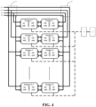
- FIG. 4 is a schematic structural diagram of a test system for power conversion devices provided in an embodiment of the present application.
- the test system similar to the test system for power conversion devices shown in the embodiment of FIG. 2 , the test system also includes: a first AC input/output section 1, a second AC input/output section 2, a control unit 3 and an evaluation unit 4.
- the test system shown in the embodiment of FIG. 4 includes multiple groups of power conversion devices. Each group of power conversion devices in the multiple groups of power conversion devices includes two back-to-back serially connected power conversion devices as shown in the embodiment of FIG. 2 .
- FIG. 1 is a schematic structural diagram of a test system for power conversion devices provided in an embodiment of the present application.
- the test system also includes: a first AC input/output section 1, a second AC input/output section 2, a control unit 3 and an evaluation unit 4.
- the test system shown in the embodiment of FIG. 4 includes multiple groups of power conversion devices. Each group of power conversion devices in the multiple groups of power conversion devices includes two back-to-
- test system shown in FIG. 4 includes two groups of power conversion devices, and each group of power conversion devices includes two back-to-back serially connected power conversion devices.
- the four power conversion devices included in the test system of the power conversion devices are numbered as a first power conversion device in a first group of power conversion devices, a second power conversion device in the first group of power conversion devices, a first power conversion device in a second group of power conversion devices, and a second power conversion device in the second group of power conversion devices.
- control unit 3 can control the first power conversion device in the first group of power conversion devices and the first power conversion device/second power conversion device in the second group of power conversion devices to work in the first working mode, and control the second power conversion device in the first group of power conversion devices and the second power conversion device/first power conversion device in the second group of power conversion devices to work in the second working mode.
- it can control the first power conversion device in the first group of power conversion devices and the first power conversion device/second power conversion device in the second group of power conversion devices to work in second first working mode, and control the second power conversion device in the first group of power conversion devices and the second power conversion device/first power conversion device in the second group of power conversion devices to work in the first working mode.
- Steps (1) and (2) an exemplary implementation is described in Steps (1) and (2) by way of example in which the first power conversion device is controlled to work in the first working mode and the second power conversion device is controlled to work in the second working mode; and then the first power conversion device is controlled to work in the second working mode, and the second power conversion device is controlled to work in the first working mode.
- control unit 3 may include a relay control board and a plurality of relays.
- the plurality of relays are arranged on the relay control board.
- the first power conversion device and the second power conversion device are respectively connected to corresponding relays, so the control unit 3 can switch the communication of the first power conversion device and the second power conversion device through the relays.
- Step (1) when Step (1) is performed, a first relay corresponding to the first power conversion device is controlled to close, and a first turn-on instruction is sent to the first power conversion device, to enable the first power conversion device to undergo the first stage of charge and discharge in the first working mode.
- the first relay is controlled to open, a second relay corresponding to the second power conversion device is controlled to close, and a second turn-on instruction is sent to the second power conversion device, to enable the second power conversion device to undergo the first stage of charge and discharge in the second working mode.
- the first turn-on instruction may be an instruction preset in the host computer for enabling the first power conversion device to work in the first working mode.
- the first turn-on instruction may be ID180180A0 instruction 61009411000009411 and instruction 65009411D0079411.
- the first power conversion device and the second power conversion device can undergo the first stage of charge and discharge in different working modes.
- the first power conversion device works in the first working mode based on the first turn-on instruction, it can receive an AC power from the grid, convert the AC power into a DC power and output it to the second power conversion device.
- the second power conversion device works in the second working mode based on the second turn-on instruction, it can receive the DC power output from the first power conversion device, convert the DC power into an AC power and output it to the grid.
- Step (2) may not be performed to control the first power conversion device to undergo a second stage of charge and discharge in the second working mode.
- the first power conversion device cannot provide a power or act as a load for the second power conversion device, and the second power conversion device cannot be tested normally. Therefore, the second power conversion device has no need to be controlled to undergo a second stage of charge and discharge in the first working mode through Step (2).
- Step (2) is not performed.
- Step 6031 it is determined in Step 6031 that the second power conversion device is abnormal during the first stage of charge and discharge, the first stage of charge and discharge is stopped to end the aging test, and Step (2) is not performed.
- Step (2) The operation of stopping the first stage of charge and discharge to end the aging test will be described in detail in Step (2) below.
- Step (2) The first power conversion device is controlled to undergo a second stage of charge and discharge in the second working mode and the second power conversion device is controlled to undergo a second stage of charge and discharge in the first working mode by the control unit 3 when the first stage of charge and discharge ends.
- Step (2) can be performed after the first power conversion device is charged and discharged for 5 h in the first working mode and the second power conversion device is charged and discharged in the second working mode for 5 h.
- Step (2) is performed to continue the aging test when it is determined that neither the first power conversion device nor the second power conversion device is abnormal during the first stage of charge and discharge, and the first stage of charge and discharge is completed.
- the abnormality is marked. For example, if it is determined that the first power conversion device and/or the second power conversion device is/are abnormal during the first stage of charge and discharge, the first data flag bit is set to 1. A first data flag bit of 0 indicates that there is no abnormality. Generally, the host computer will set the data flag bit to 0 after starting the test system, and the first data flag bit is used to mark the abnormality during the first stage of charge and discharge. Moreover, during the first stage of the charge and discharge test, if there is an abnormality, a technician can press the stop button to trigger a test stop instruction.
- the host computer receives the test stop instruction, and record the test stop event through the first data flag bit. For example, if the first data flag bit is currently 1, the upper computer may not modify the first data flag bit. If the first data flag bit is currently 0, the host computer can set the first data flag bit to 1.
- Step (2) is performed to undergo the second stage of charge and discharge and continue the aging test when it is determined that the first data flag bit is 0, and the first stage of charge and discharge is completed. Otherwise, the aging test is stopped.
- Step (2) when Step (2) is performed, the second power conversion device is controlled to stop the first stage of charge and discharge in the second working mode, and then the first power conversion device is controlled to stop the first stage of charge and discharge in the first working mode. Then, a first turn-on instruction is sent to the second power conversion device, to enable the second power conversion device to undergo the second stage of charge and discharge in the first working mode. Finally, a second turn-on instruction is sent to the first power conversion device, to enable the first power conversion device to undergo the second stage of charge and discharge in the second working mode.
- Step (1) for the sake of safe operation, the principle of turning on the power first and then turning on the load is generally followed.
- the power is turned off, the principle of turning off the load first and then turning off the power is generally followed. Therefore, in Step (2), the second power conversion device is controlled to stop the first stage of charge and discharge in the second working mode, then the first power conversion device is controlled to stop the first stage of charge and discharge in the first working mode, then the second power conversion device is controlled to undergo the second stage of charge and discharge in the first working mode, and finally the first power conversion device is controlled to undergo the second stage of charge and discharge in the second working mode.
- the second relay corresponding to the second power conversion device is controlled to close, and the communication state between the second power conversion device and the control unit 3 is switched from non-communication to communication, so that the control unit 3 can send a first turn-off instruction to the second power conversion device to enable the second power conversion device to stop the first stage of charge and discharge in the second working mode.
- the first turn-off instruction may be an instruction preset in the host computer for enabling the second power conversion device to stop working in the second working mode.
- the first turn-off instruction may be ID180180A0 instruction E2009411000009411.
- the second turn-off instruction may be an instruction preset in the host computer for enabling the first power conversion device to stop working in the first working mode.
- the second turn-off instruction may be ID180180A0 instruction 6200941100009411.
- the second relay corresponding to the second power conversion device is controlled to close, and the communication state between the second power conversion device and the control unit 3 is switched from non-communication to communication, so that the control unit 3 can send a first turn-on instruction to the second power conversion device, to enable the second power conversion device to undergo the second stage of charge and discharge in the first working mode.
- the first turn-on instruction may be an instruction preset in the host computer for enabling the second power conversion device to work in the first working mode.
- the second relay is controlled to open, the first relay corresponding to the first power conversion device is controlled to close, and the communication state between the first power conversion device and the control unit 3 is switched from non-communication to communication, so that the control unit 3 can send a second turn-on instruction to the first power conversion device, to enable the first power conversion device to undergo the second stage of charge and discharge in the second working mode.
- the second turn-on instruction may be an instruction preset in the host computer for enabling the first power conversion device to work in the second working mode.
- the first power conversion device and the second power conversion device can undergo the second stage of charge and discharge in different working modes.
- the second power conversion device works in the first working mode based on the first turn-on instruction, it can receive an AC power from the grid, convert the AC power into a DC power and output it to the first power conversion device.
- the first power conversion device works in the second working mode based on the second turn-on instruction, it can receive the DC power output from the second power conversion device, convert the DC power into an AC power and output it to the grid.
- the host computer may perform communication pre-check on the test system, so as to facilitate troubleshooting of the test system.
- the relay may control the first relay corresponding to the first power conversion device to close, and determine whether there is a data change in the life frame. If there is a data change in the life frame, it indicates that the communication of the first power conversion device is normal; otherwise, it indicates that the communication of the first power conversion device is abnormal. Then, the first relay is controlled to open, and the second relay corresponding to the second power conversion device is controlled to close, and whether there is a data change in the life frame is determined.
- Step 603 Obtain the test data of the first power conversion device and the second power conversion device when they work in different working modes, and evaluate the first power conversion device and the second power conversion device according to the test data.
- the evaluation unit 4 can evaluate the first power conversion device according to the test data when the first power conversion device works in the first working mode and the test data when the first power conversion device works in the second working mode, and evaluate the second power conversion device according to the test data when the second power conversion device works in the second working mode and the test data when the second power conversion device works in the first working mode.
- the evaluation of the first power conversion device may be determining whether the first power conversion device is abnormally charged and discharged
- the evaluation of the second power conversion device may be determining whether the second power conversion device is abnormally charged and discharged.
- the second relay is controlled to open, and the first relay corresponding to the first power conversion device is controlled to close, and all test data of the first power conversion device in the first stage of charge and discharge in the first working mode is collected. This is not limited in the embodiment of the present application.
- the host computer stores the first charge and discharge data.
- the obtained first charge and discharge data may be displayed for check by the technicians.
- the first charge and discharge data can be stored and displayed in the form of a table or a graph, so that the storage efficiency is improved, and the intuitiveness and readability of the data is improved.
- an aging configuration table includes thresholds of various aging parameters, and may respectively include a first threshold range of each aging parameter when the power conversion device undergoes the first stage of charge and discharge in the first working mode and the second working mode.
- the host computer can receive the aging configuration table after starting the test system, and can obtain, based on the aging configuration table, the first threshold range of each aging parameter when the first stage of charge and discharge is performed in the first working mode and the first threshold range of each aging parameter when the first stage of charge and discharge is performed in the second working mode.
- Step 6031 If it is determined in Step 6031 that the first power conversion device is not abnormal during the first stage of charge and discharge, and it is determined in Step 6032 that the first power conversion device is not abnormal during the second stage of charge and discharge, the first power conversion device is determined to be not failed. Otherwise, the first power conversion device is determined to be a failed product. Similarly, if it is determined in Step 6031 that the second power conversion device is not abnormal during the first stage of charge and discharge, and it is determined in Step 6032 that the second power conversion device is not abnormal during the second stage of charge and discharge, the second power conversion device is determined to be not failed. Otherwise, the second power conversion device is determined to be a failed product.
- the first charge and discharge data is the test data of the odd-numbered power conversion devices in the serially connected sequence in this group of power conversion devices in the first stage of charge and discharge in the first working mode and the test data of the even-numbered power conversion devices in the serially connected sequence in the first stage of charge and discharge in the second working mode.
- the second charge and discharge data is the test data of the odd-numbered power conversion devices in the serially connected sequence in this group of power conversion devices in the second stage of charge and discharge in the second working mode and the test data of the even-numbered power conversion devices in the serially connected sequence in the second stage of charge and discharge in the first working mode.
- the embodiment of the present application provides a third test method for power conversion devices.
- the third step of the method comprises obtaining test data of the odd-numbered and the even-numbered power conversion devices in the serially connected sequence in each group of power conversion devices in the multiple groups of power conversion devices when they work in different working modes, and evaluating each power conversion device in the multiple groups of power conversion devices according to the test data.
- first charge and discharge data and second charge and discharge data are obtained, and whether each of the power conversion devices in the multiple groups of power conversion devices is abnormally charged and discharged is determined according to the first charge and discharge data and the second charge and discharge data.
- the first charge and discharge data is the test data of the odd-numbered power conversion devices in the serially connected sequence in each group of power conversion devices in the first stage of charge and discharge in the first working mode and the test data of the even-numbered power conversion devices in the serially connected sequence in the first stage of charge and discharge in the second working mode.
- the second charge and discharge data is the test data of the odd-numbered power conversion devices in the serially connected sequence in each group of power conversion devices in the second stage of charge and discharge in the second working mode and the test data of the even-numbered power conversion devices in the serially connected sequence in the second stage of charge and discharge in the first working mode.
- each group of power conversion devices in the test system shown in the embodiment of FIG. 5 includes multiple pairs of power conversion devices and each pair of power conversion devices in the multiple pairs of power conversion devices includes two back-to-back serially connected power conversion devices. If a power conversion device is abnormal during the first stage of charge and discharge, not all the first stages of charge and discharge are stopped to end the aging test, but only the first stage of charge and discharge of the power conversion device with abnormal charge and discharge and a power conversion device paired therewith are stopped, and the second stage of charge and discharge of the pair of power conversion devices are performed. The aging test of other pairs and other groups of power conversion devices can be carried out normally.
- Embodiments of the present application further provides a computer-readable storage medium storing a computer program or instruction.
- the computer program or instruction is executed by a processor, the test method for power conversion devices provided in any of the above method embodiments is implemented.
- Examples of computer-readable mediums include, but are not limited to, an electronic circuit, a semiconductor memory device, a Read-Only Memory (ROM), a flash memory, an erasable ROM (EROM), a floppy disk, a CD-ROM, an optical disk, a hard disk, an optic fiber medium, a radio frequency (Radio Frequency, RF) link, and the like.
- ROM Read-Only Memory
- EROM erasable ROM
- CD-ROM compact disc-read only memory
- optical disk a hard disk
- optic fiber medium a radio frequency (Radio Frequency, RF) link
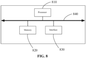
- Fig. 8 is a schematic structural diagram of another test apparatus for power conversion devices provided in an embodiment of the present application.
- the test apparatus for the power conversion devices includes: a processor 810, a memory 820, and an interface 830.
- the processor 810, the memory 820, and the interface 830 are connected by a bus 840, which can be implemented by connecting circuits.
- the memory 820 is configured to store a program, and when the program is called by the processor 810, the method implemented by the test apparatus for power conversion devices in the above embodiment can be accomplished.
- the interface 830 enables communication with other test apparatuses for power conversion devices, and the interface 830 can communicate with other test apparatuses for power conversion devices through wired connection or wireless connection.
- each unit of the test apparatus for power conversion devices can be achieved by the processor 810 calling the program stored in the memory 820. That is, the test apparatus for power conversion devices includes the processor 810 and the memory 820 used for storing a program, where the program is called by the processor 810 to implement the method in the above method embodiments.
- the processor 810 here can be a general-purpose processor, or other processors that can call a program.
- the processor 810 can be configured as one or more integrated circuits implementing the method performed by the test apparatus for power conversion devices in the above embodiments, such as: one or more application specific integrated circuit (ASIC), one or more digital signal processor (DSP), one or more field programmable gate arrays (FPGA) or other programmable logic devices, discrete gate or transistor logic devices, discrete hardware components, etc.
- ASIC application specific integrated circuit
- DSP digital signal processor
- FPGA field programmable gate arrays
- the unit in the test apparatus for power conversion devices can be implemented by a processor calling a program
- the processor 810 can be a general-purpose processor, such as a central processing unit (CPU), a controller, a microcontroller, a single-chip microcomputer or other processor that can call a program.
- these units can be integrated and implemented in the form of a system-on-chip.
- the number of the memory 820 is not limited, and may be one or more.
- the memory 820 includes at least one type of readable storage medium, and the readable storage medium includes non-volatile memory or volatile memory, for example, flash memory, hard disk, multimedia card, card type memory (for example, SD or DX memory, etc.), random access memory (RAM), read-only memory (ROM), erasable programmable read-only memory (EPROM), electrically erasable programmable read-only memory (EEPROM), programmable read-only memory (PROM), magnetic memory, magnetic disk or optical disk, etc.
- RAM can include Static RAM or Dynamic RAM.
- the memory 820 may be an internal memory of the apparatus, for example, the hard disk or memory of the apparatus.
- the memory 820 may also be an external storage device of the apparatus, for example, a plug-in hard disk, a smart media card (SMC), a secure digital (SD) card or a flash card equipped on the apparatus.
- the memory 820 may also include both the internal memory and external storage device of the apparatus.
- the memory 820 is generally configured to store an operating system and various application software installed in the apparatus, such as program codes of the test method for power conversion devices, and the like.
- the memory 820 may also be configured to temporarily store various types of data that have been output or will be output.
- the bus 840 may be an industry standard architecture (ISA) bus, a peripheral component interconnect (PCI) bus, an extended industry standard architecture (EISA) bus, or the like.
- ISA industry standard architecture
- PCI peripheral component interconnect
- EISA extended industry standard architecture
- the bus 840 may include an address bus, a data bus, a control bus, or the like. For ease of illustration, only one thick line is used in the figure, but it does not mean that there is only one bus or one type of bus.
- the processor 810 is typically configured to control the overall operation of the apparatus.
- the memory 820 is used for storing program codes or instructions, where the program codes include computer operation instructions.
- the processor 810 is configured to execute the program codes or instructions stored in the memory 820 or process data, such as program codes for running the test method for power conversion devices.
- the power supply grid is connected to the AC terminal of the first power conversion device, the power supply grid is also connected to the AC terminal of the second power conversion device, and the DC terminal of the first power conversion device is connected to the DC terminal of the second power conversion device.
- a test loop can be formed by the power supply grid, the first power conversion device and the second power conversion device.
- the control unit 3 can control the first power conversion device and the second power conversion device to work simultaneously in different working modes, and the evaluation unit 4 can obtain the test data of the first power conversion device and the second power conversion device when they work in different working modes, and evaluate the first power conversion device and the second power conversion device according to the test data.
- the first power conversion device and the second power conversion device can act as a load and a power source, so no additional DC power supply and load are required during the test, thus saving the investment cost and energy consumption.
- the first power conversion device and the second power conversion device work simultaneously in different working modes, so the test can be performed on the first power conversion device and the second power conversion device at the same time, which improves the test efficiency.
Landscapes
- Physics & Mathematics (AREA)
- General Physics & Mathematics (AREA)
- Engineering & Computer Science (AREA)
- Power Engineering (AREA)
- Inverter Devices (AREA)
- Rectifiers (AREA)
Claims (12)
- Testsystem für Stromrichtervorrichtungen, umfassend:einen ersten AC(Wechselstrom)-Eingangs-/-Ausgangsabschnitt (1), konfiguriert zum Verbinden eines Stromversorgungsnetzes und eines AC-Anschlusses einer ersten Stromrichtervorrichtung;einen zweiten AC-Eingangs-/-Ausgangsabschnitt (2), konfiguriert zum Verbinden des Stromversorgungsnetzes und eines AC-Anschlusses einer zweiten Stromrichtervorrichtung, wobei ein DC(Gleichstrom)-Anschluss der ersten Stromrichtervorrichtung mit einem DC-Anschluss der zweiten Stromrichtervorrichtung verbunden ist, wobei die erste Stromrichtervorrichtung und die zweite Stromrichtervorrichtung bidirektionale AC/DC-Wandlervorrichtungen unter Test sind;eine Steuereinheit (3), konfiguriert zum Steuern der ersten Stromrichtervorrichtung und der zweiten Stromrichtervorrichtung für gleichzeitiges Arbeiten in unterschiedlichen Arbeitsmodi, wobei die Arbeitsmodi einen ersten Arbeitsmodus und einen zweiten Arbeitsmodus umfassen; wobei die erste Stromrichtervorrichtung im ersten Arbeitsmodus arbeitet und die zweite Stromrichtervorrichtung im zweiten Arbeitsmodus arbeitet; oderdie erste Stromrichtervorrichtung im zweiten Arbeitsmodus arbeitet und die zweite Stromrichtervorrichtung im ersten Arbeitsmodus arbeitet,wobei der erste Arbeitsmodus ein AC-Eingangs- und DC-Ausgangsmodus ist und der zweite Arbeitsmodus ein DC-Eingangs- und AC-Ausgangsmodus ist, undeine Auswerteeinheit (4), konfiguriert zum Erfassen der Testdaten der ersten Stromrichtervorrichtung und der zweiten Stromrichtervorrichtung, wenn sie in beiden Arbeitsmodi arbeiten, und zum Auswerten der ersten Stromrichtervorrichtung und der zweiten Stromrichtervorrichtung gemäß den Testdaten.
- System nach Anspruch 1, wobei die Steuereinheit eine Relaissteuerplatine und eine Mehrzahl von Relais umfasst;
wobei die Mehrzahl von Relais auf der Relaissteuerplatine angeordnet sind; die erste Stromrichtervorrichtung und die zweite Stromrichtervorrichtung jeweils mit unterschiedlichen Relais verbunden sind, und die Relais zum Umschalten der Kommunikation der ersten Stromrichtervorrichtung und der zweiten Stromrichtervorrichtung konfiguriert sind. - Testverfahren für Stromrichtervorrichtungen, umfassend:Verbinden (601) eines Stromversorgungsnetzes jeweils mit einem AC-Anschluss einer ersten Stromrichtervorrichtung und einem AC-Anschluss einer zweiten Stromrichtervorrichtung;Verbinden eines DC-Anschlusses der ersten Stromrichtervorrichtung mit einem DC-Anschluss der zweiten Stromrichtervorrichtung, wobei die erste Stromrichtervorrichtung und die zweite Stromrichtervorrichtung bidirektionale AC/DC-Wandlervorrichtungen unter Test sind;Steuern (602) der ersten Stromrichtervorrichtung und der zweiten Stromrichtervorrichtung für gleichzeitiges Arbeiten in unterschiedlichen Arbeitsmodi, wobei die Arbeitsmodi einen ersten Arbeitsmodus und einen zweiten Arbeitsmodus umfassen; wobei die erste Stromrichtervorrichtung im ersten Arbeitsmodus arbeitet und die zweite Stromrichtervorrichtung im zweiten Arbeitsmodus arbeitet; oderdie erste Stromrichtervorrichtung im zweiten Arbeitsmodus arbeitet und die zweite Stromrichtervorrichtung im ersten Arbeitsmodus arbeitet,wobei der erste Arbeitsmodus ein AC-Eingangs- und DC-Ausgangsmodus ist und der zweite Arbeitsmodus ein DC-Eingangs- und AC-Ausgangsmodus ist; undErfassen (603) von Testdaten der ersten Stromrichtervorrichtung und der zweiten Stromrichtervorrichtung, wenn sie in beiden Arbeitsmodi arbeiten, und Auswerten der ersten Stromrichtervorrichtung und der zweiten Stromrichtervorrichtung gemäß den Testdaten.
- Verfahren nach Anspruch 3, wobei die Steuereinheit eine Relaissteuerplatine und eine Mehrzahl von Relais umfasst;
wobei die Mehrzahl von Relais auf der Relaissteuerplatine angeordnet sind; die erste Stromrichtervorrichtung und die zweite Stromrichtervorrichtung jeweils mit unterschiedlichen Relais verbunden sind, und die Relais zum Umschalten der Kommunikation der ersten Stromrichtervorrichtung und der zweiten Stromrichtervorrichtung konfiguriert sind. - Verfahren nach Anspruch 3, wobei das Steuern der ersten Stromrichtervorrichtung und der zweiten Stromrichtervorrichtung zum gleichzeitigen Arbeiten in unterschiedlichen Arbeitsmodi Folgendes umfasst:Steuern der ersten Stromrichtervorrichtung, einer ersten Stufe des Aufladens und Entladens im ersten Arbeitsmodus unterzogen zu werden, und Steuern der zweiten Stromrichtervorrichtung, einer ersten Stufe des Aufladens und Entladens im zweiten Arbeitsmodus unterzogen zu werden; undSteuern der ersten Stromrichtervorrichtung, einer zweiten Stufe des Aufladens und Entladens im zweiten Arbeitsmodus unterzogen zu werden und Steuern der zweiten Stromrichtervorrichtung, einer zweiten Stufe des Aufladens und Entladens im ersten Arbeitsmodus unterzogen zu werden, wenn die erste Stufe des Aufladens und Entladens beendet ist.
- Verfahren nach Anspruch 5, wobei das Steuern der ersten Stromrichtervorrichtung, einer ersten Stufe des Aufladens und Entladens im ersten Arbeitsmodus unterzogen zu werden, und das Steuern der zweiten Stromrichtervorrichtung, einer ersten Stufe des Aufladens und Entladens im zweiten Arbeitsmodus unterzogen zu werden, Folgendes umfassen:Steuern eines ersten Relais, das der ersten Stromrichtervorrichtung entspricht, zu schließen und Senden einer ersten Anschaltinstruktion an die erste Stromrichtervorrichtung, um der ersten Stromrichtervorrichtung zu ermöglichen, der ersten Stufe des Aufladens und Entladens im ersten Arbeitsmodus unterzogen zu werden; undSteuern des ersten Relais, zu öffnen, Steuern eines zweiten Relais, das der zweiten Stromrichtervorrichtung entspricht, zu schließen und Senden einer zweiten Anschaltinstruktion an die zweite Stromrichtervorrichtung, um der zweiten Stromrichtervorrichtung zu ermöglichen, der ersten Stufe des Aufladens und Entladens im zweiten Arbeitsmodus unterzogen zu werden.
- Verfahren nach Anspruch 5, wobei das Steuern der ersten Stromrichtervorrichtung, einer zweiten Stufe des Aufladens und Entladens im zweiten Arbeitsmodus unterzogen zu werden, und das Steuern der zweiten Stromrichtervorrichtung, einer zweiten Stufe des Aufladens und
Entladens im ersten Arbeitsmodus unterzogen zu werden, Folgendes umfassen:Steuern der zweiten Stromrichtervorrichtung, die erste Stufe des Aufladens und Entladens im zweiten Arbeitsmodus zu stoppen, und Steuern der ersten Stromrichtervorrichtung, die erste Stufe des Aufladens und Entladens im ersten Arbeitsmodus zu stoppen;Senden einer ersten Anschaltinstruktion an die zweite Stromrichtervorrichtung, um der zweiten Stromrichtervorrichtung zu ermöglichen, der zweiten Stufe des Aufladens und Entladens im ersten Arbeitsmodus unterzogen zu werden; undSenden einer zweiten Anschaltinstruktion an die erste Stromrichtervorrichtung, um der ersten Stromrichtervorrichtung zu ermöglichen, der zweiten Stufe des Aufladens und Entladens im zweiten Arbeitsmodus unterzogen zu werden. - Verfahren nach Anspruch 7, wobei das Steuern der zweiten Stromrichtervorrichtung, die erste Stufe des Aufladens und Entladens im zweiten Arbeitsmodus zu stoppen, und das Steuern der ersten Stromrichtervorrichtung, die erste Stufe des Aufladens und Entladens im ersten Arbeitsmodus zu stoppen, Folgendes umfassen:Steuern des zweiten Relais, das der zweiten Stromrichtervorrichtung entspricht, zu schließen und Senden einer ersten Abschaltinstruktion an die zweite Stromrichtervorrichtung, um der zweiten Stromrichtervorrichtung zu ermöglichen, die erste Stufe des Aufladens und Entladens im zweiten Arbeitsmodus zu stoppen; undSteuern des zweiten Relais, zu öffnen, Steuern des ersten Relais, das der ersten Stromrichtervorrichtung entspricht, zu schließen und Senden einer zweiten Abschaltinstruktion an die erste Stromrichtervorrichtung, um der ersten Stromrichtervorrichtung zu ermöglichen, die erste Stufe des Aufladens und Entladens im ersten Arbeitsmodus zu stoppen.
- Verfahren nach Anspruch 3, wobei das Erfassen von Testdaten der ersten Stromrichtervorrichtung und der zweiten Stromrichtervorrichtung, wenn sie in unterschiedlichen Arbeitsmodi arbeiten, und das Auswerten der ersten Stromrichtervorrichtung und der zweiten Stromrichtervorrichtung gemäß den Testdaten Folgendes umfassen:Erfassen erster Aufladungs- und Entladungsdaten und Bestimmen, ob die erste Stromrichtervorrichtung und die zweite Stromrichtervorrichtung sich während der ersten Stufe des Aufladens und Entladens gemäß den ersten Aufladungs- und Entladungsdaten unnormal verhalten, wobei die ersten Aufladungs- und Entladungsdaten die Testdaten der ersten Stromrichtervorrichtung in der ersten Stufe des Aufladens und Entladens im ersten Arbeitsmodus und die Testdaten der zweiten Stromrichtervorrichtung in der ersten Stufe des Aufladens und Entladens im zweiten Arbeitsmodus sind; undErfassen zweiter Aufladungs- und Entladungsdaten und Bestimmen, ob die erste Stromrichtervorrichtung und die zweite Stromrichtervorrichtung sich während der zweiten Stufe des Aufladens und Entladens gemäß den zweiten Aufladungs- und Entladungsdaten unnormal verhalten, wobei die zweiten Aufladungs- und Entladungsdaten die Testdaten der ersten Stromrichtervorrichtung in der zweiten Stufe des Aufladens und Entladens im zweiten Arbeitsmodus und die Testdaten der zweiten Stromrichtervorrichtung in der zweiten Stufe des Aufladens und Entladens im ersten Arbeitsmodus sind.
- Verfahren nach Anspruch 9, wobei das Bestimmen, ob die erste Stromrichtervorrichtung und die zweite Stromrichtervorrichtung sich in der ersten Stufe des Aufladens und Entladens gemäß den ersten Aufladungs- und Entladungsdaten unnormal verhalten, Folgendes umfasst:wenn die ersten Aufladungs- und Entladungsdaten der ersten Stromrichtervorrichtung über einen ersten Schwellenbereich hinaus gehen, Bestimmen, dass die erste Stromrichtervorrichtung sich in der ersten Stufe des Aufladens und Entladens unnormal verhält; undwenn die ersten Aufladungs- und Entladungsdaten der zweiten Stromrichtervorrichtung über einen ersten Schwellenbereich hinaus gehen, Bestimmen, dass die zweite Stromrichtervorrichtung sich in der ersten Stufe des Aufladens und Entladens unnormal verhält.
- Computerlesbares Speichermedium mit einem darauf gespeicherten Computerprogramm, wobei bei Ausführung des Computerprogramms durch einen Prozessor und eine elektronische Vorrichtung das Testverfahren für Stromrichtervorrichtungen nach einem der Ansprüche 3 bis 10 implementiert wird.
- Elektronische Vorrichtung, umfassend:einen Prozessor; undeinen Arbeitsspeicher zum Speichern von durch den Prozessor ausführbaren Instruktionen, wobei der Prozessor und die elektronische Vorrichtung dazu konfiguriert sind, durch Ausführen der ausführbaren Instruktionen das Testverfahren für Stromrichtervorrichtungen nach einem der Ansprüche 3 bis 10 zu implementieren.
Applications Claiming Priority (2)
| Application Number | Priority Date | Filing Date | Title |
|---|---|---|---|
| CN202110877278.7A CN115684757B (zh) | 2021-07-31 | 2021-07-31 | 电源转换装置的测试系统、方法、电子设备及存储介质 |
| PCT/CN2022/101835 WO2023011051A1 (zh) | 2021-07-31 | 2022-06-28 | 电源转换装置的测试系统、方法、电子设备及存储介质 |
Publications (4)
| Publication Number | Publication Date |
|---|---|
| EP4224176A1 EP4224176A1 (de) | 2023-08-09 |
| EP4224176A4 EP4224176A4 (de) | 2024-06-05 |
| EP4224176B1 true EP4224176B1 (de) | 2025-07-02 |
| EP4224176C0 EP4224176C0 (de) | 2025-07-02 |
Family
ID=85059781
Family Applications (1)
| Application Number | Title | Priority Date | Filing Date |
|---|---|---|---|
| EP22851767.8A Active EP4224176B1 (de) | 2021-07-31 | 2022-06-28 | Testsystem und verfahren für eine leistungsumwandlungsvorrichtung sowie elektronische vorrichtung und speichermedium |
Country Status (8)
| Country | Link |
|---|---|
| US (1) | US12392844B2 (de) |
| EP (1) | EP4224176B1 (de) |
| JP (1) | JP7578814B2 (de) |
| KR (1) | KR102828357B1 (de) |
| CN (1) | CN115684757B (de) |
| ES (1) | ES3041658T3 (de) |
| HU (1) | HUE072899T2 (de) |
| WO (1) | WO2023011051A1 (de) |
Families Citing this family (2)
| Publication number | Priority date | Publication date | Assignee | Title |
|---|---|---|---|---|
| KR102838762B1 (ko) * | 2021-10-27 | 2025-07-24 | 컨템포러리 엠퍼렉스 테크놀로지 (홍콩) 리미티드 | 직병렬 전환 방법 및 장치, 전원전환회로와 전자기기 |
| CN120546099B (zh) * | 2025-05-21 | 2026-04-24 | 阿特斯储能科技有限公司 | 一种对拖系统及其控制方法、装置 |
Family Cites Families (21)
| Publication number | Priority date | Publication date | Assignee | Title |
|---|---|---|---|---|
| EP0713614B1 (de) * | 1994-06-15 | 1999-10-06 | Koninklijke Philips Electronics N.V. | Leistungsversorgungseinrichtung mit leistungsfaktorverbesserungsschaltung |
| JP4242619B2 (ja) | 2002-09-09 | 2009-03-25 | 東芝三菱電機産業システム株式会社 | 自励式変換器の試験方法 |
| TW200419884A (en) * | 2003-03-17 | 2004-10-01 | Phoenixtec Ind Co Ltd | Control method of UPS module connected in parallel and system thereof |
| KR101372533B1 (ko) * | 2007-11-20 | 2014-03-11 | 엘지전자 주식회사 | 전동기 제어장치 |
| CN201238203Y (zh) * | 2008-07-30 | 2009-05-13 | 上海根兴电气成套有限公司 | 微机控制型不间断电源柜 |
| US8559197B2 (en) * | 2008-10-13 | 2013-10-15 | Infinia Corporation | Electrical control circuits for an energy converting apparatus |
| CN101834527B (zh) * | 2009-03-12 | 2012-12-12 | 台达电子工业股份有限公司 | 双级交换式电源转换电路 |
| CN201479019U (zh) * | 2009-08-24 | 2010-05-19 | 上海根兴电气成套有限公司 | 微机控制型不间断多输出电源柜 |
| US9219426B2 (en) * | 2012-02-09 | 2015-12-22 | Hitachi, Ltd. | Switching element, power converter, direct current transmission system, current control device, method of controlling power converter, and method of controlling current in voltage source converter |
| TWI479784B (zh) * | 2013-03-18 | 2015-04-01 | Power Forest Technology Corp | 交流直流轉換電路 |
| CN203537240U (zh) * | 2013-11-22 | 2014-04-09 | 哈尔滨宏宇整流开关厂 | 一种模压台变频电源智能温控装置 |
| JP6371254B2 (ja) | 2015-05-13 | 2018-08-08 | 東芝三菱電機産業システム株式会社 | 電力変換装置 |
| JP6844618B2 (ja) * | 2016-05-18 | 2021-04-07 | 株式会社村田製作所 | 電力供給装置 |
| CN107696863B (zh) * | 2016-08-08 | 2020-03-31 | 比亚迪股份有限公司 | 电动汽车的能量管理系统及其控制方法、电动汽车 |
| US9860075B1 (en) | 2016-08-26 | 2018-01-02 | At&T Intellectual Property I, L.P. | Method and communication node for broadband distribution |
| CN206149013U (zh) * | 2016-11-17 | 2017-05-03 | 青岛创统新智能源科技有限公司 | 一种支持老化自检测的不间断电源 |
| US11428748B2 (en) * | 2017-11-10 | 2022-08-30 | Mitsubishi Electric Corporation | System and method for testing power conversion device |
| JP6802826B2 (ja) * | 2018-09-13 | 2020-12-23 | 矢崎総業株式会社 | 車両電源装置 |
| TWI695177B (zh) * | 2018-12-14 | 2020-06-01 | 財團法人船舶暨海洋產業研發中心 | 電力轉換器滿載測試系統及其測試方法 |
| CN111953068B (zh) * | 2019-05-17 | 2022-04-15 | 台达电子工业股份有限公司 | 电力转换系统及其操作方法 |
| CN110341517A (zh) * | 2019-06-06 | 2019-10-18 | 深圳先进技术研究院 | 一种电能双向转换装置、电动车以及电动车供电系统 |
-
2021
- 2021-07-31 CN CN202110877278.7A patent/CN115684757B/zh active Active
-
2022
- 2022-06-28 ES ES22851767T patent/ES3041658T3/es active Active
- 2022-06-28 JP JP2023524167A patent/JP7578814B2/ja active Active
- 2022-06-28 HU HUE22851767A patent/HUE072899T2/hu unknown
- 2022-06-28 EP EP22851767.8A patent/EP4224176B1/de active Active
- 2022-06-28 KR KR1020237014059A patent/KR102828357B1/ko active Active
- 2022-06-28 WO PCT/CN2022/101835 patent/WO2023011051A1/zh not_active Ceased
-
2023
- 2023-05-01 US US18/310,065 patent/US12392844B2/en active Active
Also Published As
| Publication number | Publication date |
|---|---|
| WO2023011051A1 (zh) | 2023-02-09 |
| JP2023546215A (ja) | 2023-11-01 |
| US20230384395A1 (en) | 2023-11-30 |
| KR102828357B1 (ko) | 2025-07-01 |
| CN115684757B (zh) | 2024-04-09 |
| US12392844B2 (en) | 2025-08-19 |
| EP4224176C0 (de) | 2025-07-02 |
| KR20230071186A (ko) | 2023-05-23 |
| CN115684757A (zh) | 2023-02-03 |
| JP7578814B2 (ja) | 2024-11-06 |
| EP4224176A4 (de) | 2024-06-05 |
| ES3041658T3 (en) | 2025-11-13 |
| EP4224176A1 (de) | 2023-08-09 |
| HUE072899T2 (hu) | 2025-12-28 |
Similar Documents
| Publication | Publication Date | Title |
|---|---|---|
| US12392844B2 (en) | Test system and method for power conversion devices, electronic device, and storage medium | |
| JP6831281B2 (ja) | 電池監視システムおよび電池監視装置 | |
| US20140045003A1 (en) | Hybrid-type rechargeable battery module | |
| CN104216499A (zh) | 机柜与其电源控制方法 | |
| CN103809724A (zh) | 机柜与其电源控制方法 | |
| CN106787040A (zh) | 直流电源系统 | |
| CN107479645A (zh) | 一种双输入电源模块、服务器供电系统及供电方法 | |
| CN119659331A (zh) | 一种车辆供电系统、车辆供电系统的控制方法以及车辆 | |
| CN112018872B (zh) | Ups控制方法及ups | |
| US12106916B2 (en) | Relay protective device, construction machine, relay protection control method and apparatus | |
| CN117595636A (zh) | 一种变频器级联式功率单元旁路系统 | |
| CN116457236B (zh) | 电源管理系统、微控制单元、电池管理系统和电池 | |
| CN110932333A (zh) | 一种配电系统 | |
| CN203942322U (zh) | 汽车编程电源 | |
| CN216872918U (zh) | 一种柴油发电机启动装置及电子设备 | |
| CN117706430A (zh) | 逆变器的接口接线检测方法、功率变换装置及储能系统 | |
| CN105912438B (zh) | 基板控制系统、电子设备及信息处理方法 | |
| CN221380614U (zh) | 供电控制系统 | |
| CN208062500U (zh) | 一种智能通信电气柜 | |
| CN207251297U (zh) | 一种消防电源 | |
| CN115117855B (zh) | 级联型电压源换流器启动阶段的单元保护判别方法、系统、设备及介质 | |
| EP4589805A1 (de) | Verfahren, vorrichtung und steuerung zur fehlererkennung einer unterbrechungsfreien stromversorgung | |
| CN220492694U (zh) | 高效双电源自动切换电路 | |
| JP7754356B1 (ja) | 燃料電池システム | |
| CN115789891B (zh) | 一种空调的控制方法、装置、空调和存储介质 |
Legal Events
| Date | Code | Title | Description |
|---|---|---|---|
| STAA | Information on the status of an ep patent application or granted ep patent |
Free format text: STATUS: THE INTERNATIONAL PUBLICATION HAS BEEN MADE |
|
| PUAI | Public reference made under article 153(3) epc to a published international application that has entered the european phase |
Free format text: ORIGINAL CODE: 0009012 |
|
| STAA | Information on the status of an ep patent application or granted ep patent |
Free format text: STATUS: REQUEST FOR EXAMINATION WAS MADE |
|
| 17P | Request for examination filed |
Effective date: 20230504 |
|
| AK | Designated contracting states |
Kind code of ref document: A1 Designated state(s): AL AT BE BG CH CY CZ DE DK EE ES FI FR GB GR HR HU IE IS IT LI LT LU LV MC MK MT NL NO PL PT RO RS SE SI SK SM TR |
|
| A4 | Supplementary search report drawn up and despatched |
Effective date: 20240508 |
|
| RIC1 | Information provided on ipc code assigned before grant |
Ipc: H02M 5/40 20060101ALI20240502BHEP Ipc: G01R 31/00 20060101AFI20240502BHEP |
|
| RAP1 | Party data changed (applicant data changed or rights of an application transferred) |
Owner name: CONTEMPORARY AMPEREX TECHNOLOGY(HONG KONG) LIMITED |
|
| DAV | Request for validation of the european patent (deleted) | ||
| DAX | Request for extension of the european patent (deleted) | ||
| GRAP | Despatch of communication of intention to grant a patent |
Free format text: ORIGINAL CODE: EPIDOSNIGR1 |
|
| STAA | Information on the status of an ep patent application or granted ep patent |
Free format text: STATUS: GRANT OF PATENT IS INTENDED |
|
| INTG | Intention to grant announced |
Effective date: 20250205 |
|
| GRAS | Grant fee paid |
Free format text: ORIGINAL CODE: EPIDOSNIGR3 |
|
| GRAA | (expected) grant |
Free format text: ORIGINAL CODE: 0009210 |
|
| STAA | Information on the status of an ep patent application or granted ep patent |
Free format text: STATUS: THE PATENT HAS BEEN GRANTED |
|
| AK | Designated contracting states |
Kind code of ref document: B1 Designated state(s): AL AT BE BG CH CY CZ DE DK EE ES FI FR GB GR HR HU IE IS IT LI LT LU LV MC MK MT NL NO PL PT RO RS SE SI SK SM TR |
|
| REG | Reference to a national code |
Ref country code: GB Ref legal event code: FG4D |
|
| REG | Reference to a national code |
Ref country code: CH Ref legal event code: EP |
|
| REG | Reference to a national code |
Ref country code: DE Ref legal event code: R096 Ref document number: 602022017105 Country of ref document: DE |
|
| REG | Reference to a national code |
Ref country code: IE Ref legal event code: FG4D |
|
| U01 | Request for unitary effect filed |
Effective date: 20250729 |
|
| U07 | Unitary effect registered |
Designated state(s): AT BE BG DE DK EE FI FR IT LT LU LV MT NL PT RO SE SI Effective date: 20250804 |
|
| REG | Reference to a national code |
Ref country code: ES Ref legal event code: FG2A Ref document number: 3041658 Country of ref document: ES Kind code of ref document: T3 Effective date: 20251113 |
|
| REG | Reference to a national code |
Ref country code: HU Ref legal event code: AG4A Ref document number: E072899 Country of ref document: HU |
|
| PG25 | Lapsed in a contracting state [announced via postgrant information from national office to epo] |
Ref country code: IS Free format text: LAPSE BECAUSE OF FAILURE TO SUBMIT A TRANSLATION OF THE DESCRIPTION OR TO PAY THE FEE WITHIN THE PRESCRIBED TIME-LIMIT Effective date: 20251102 |
|
| PG25 | Lapsed in a contracting state [announced via postgrant information from national office to epo] |
Ref country code: NO Free format text: LAPSE BECAUSE OF FAILURE TO SUBMIT A TRANSLATION OF THE DESCRIPTION OR TO PAY THE FEE WITHIN THE PRESCRIBED TIME-LIMIT Effective date: 20251002 |
|
| PG25 | Lapsed in a contracting state [announced via postgrant information from national office to epo] |
Ref country code: HR Free format text: LAPSE BECAUSE OF FAILURE TO SUBMIT A TRANSLATION OF THE DESCRIPTION OR TO PAY THE FEE WITHIN THE PRESCRIBED TIME-LIMIT Effective date: 20250702 |
|
| PG25 | Lapsed in a contracting state [announced via postgrant information from national office to epo] |
Ref country code: GR Free format text: LAPSE BECAUSE OF FAILURE TO SUBMIT A TRANSLATION OF THE DESCRIPTION OR TO PAY THE FEE WITHIN THE PRESCRIBED TIME-LIMIT Effective date: 20251003 |
|
| PG25 | Lapsed in a contracting state [announced via postgrant information from national office to epo] |
Ref country code: CZ Free format text: LAPSE BECAUSE OF FAILURE TO SUBMIT A TRANSLATION OF THE DESCRIPTION OR TO PAY THE FEE WITHIN THE PRESCRIBED TIME-LIMIT Effective date: 20250702 |
|
| PG25 | Lapsed in a contracting state [announced via postgrant information from national office to epo] |
Ref country code: PL Free format text: LAPSE BECAUSE OF FAILURE TO SUBMIT A TRANSLATION OF THE DESCRIPTION OR TO PAY THE FEE WITHIN THE PRESCRIBED TIME-LIMIT Effective date: 20250702 |
|
| PG25 | Lapsed in a contracting state [announced via postgrant information from national office to epo] |
Ref country code: RS Free format text: LAPSE BECAUSE OF FAILURE TO SUBMIT A TRANSLATION OF THE DESCRIPTION OR TO PAY THE FEE WITHIN THE PRESCRIBED TIME-LIMIT Effective date: 20251002 |
|
| PG25 | Lapsed in a contracting state [announced via postgrant information from national office to epo] |
Ref country code: SM Free format text: LAPSE BECAUSE OF FAILURE TO SUBMIT A TRANSLATION OF THE DESCRIPTION OR TO PAY THE FEE WITHIN THE PRESCRIBED TIME-LIMIT Effective date: 20250702 |