EP4224039A1 - Vehicle transmission - Google Patents
Vehicle transmission Download PDFInfo
- Publication number
- EP4224039A1 EP4224039A1 EP23151628.7A EP23151628A EP4224039A1 EP 4224039 A1 EP4224039 A1 EP 4224039A1 EP 23151628 A EP23151628 A EP 23151628A EP 4224039 A1 EP4224039 A1 EP 4224039A1
- Authority
- EP
- European Patent Office
- Prior art keywords
- shift
- insertion member
- transmission case
- select shaft
- interlock plate
- Prior art date
- Legal status (The legal status is an assumption and is not a legal conclusion. Google has not performed a legal analysis and makes no representation as to the accuracy of the status listed.)
- Granted
Links
Images



Classifications
-
- F—MECHANICAL ENGINEERING; LIGHTING; HEATING; WEAPONS; BLASTING
- F16—ENGINEERING ELEMENTS AND UNITS; GENERAL MEASURES FOR PRODUCING AND MAINTAINING EFFECTIVE FUNCTIONING OF MACHINES OR INSTALLATIONS; THERMAL INSULATION IN GENERAL
- F16H—GEARING
- F16H61/00—Control functions within control units of change-speed- or reversing-gearings for conveying rotary motion ; Control of exclusively fluid gearing, friction gearing, gearings with endless flexible members or other particular types of gearing
- F16H61/24—Providing feel, e.g. to enable selection
-
- F—MECHANICAL ENGINEERING; LIGHTING; HEATING; WEAPONS; BLASTING
- F16—ENGINEERING ELEMENTS AND UNITS; GENERAL MEASURES FOR PRODUCING AND MAINTAINING EFFECTIVE FUNCTIONING OF MACHINES OR INSTALLATIONS; THERMAL INSULATION IN GENERAL
- F16H—GEARING
- F16H57/00—General details of gearing
- F16H57/02—Gearboxes; Mounting gearing therein
- F16H2057/02021—Gearboxes; Mounting gearing therein with means for adjusting alignment
-
- F—MECHANICAL ENGINEERING; LIGHTING; HEATING; WEAPONS; BLASTING
- F16—ENGINEERING ELEMENTS AND UNITS; GENERAL MEASURES FOR PRODUCING AND MAINTAINING EFFECTIVE FUNCTIONING OF MACHINES OR INSTALLATIONS; THERMAL INSULATION IN GENERAL
- F16H—GEARING
- F16H61/00—Control functions within control units of change-speed- or reversing-gearings for conveying rotary motion ; Control of exclusively fluid gearing, friction gearing, gearings with endless flexible members or other particular types of gearing
- F16H61/24—Providing feel, e.g. to enable selection
- F16H2061/243—Cams or detent arrays for guiding and providing feel
-
- F—MECHANICAL ENGINEERING; LIGHTING; HEATING; WEAPONS; BLASTING
- F16—ENGINEERING ELEMENTS AND UNITS; GENERAL MEASURES FOR PRODUCING AND MAINTAINING EFFECTIVE FUNCTIONING OF MACHINES OR INSTALLATIONS; THERMAL INSULATION IN GENERAL
- F16H—GEARING
- F16H63/00—Control outputs from the control unit to change-speed- or reversing-gearings for conveying rotary motion or to other devices than the final output mechanism
- F16H63/02—Final output mechanisms therefor; Actuating means for the final output mechanisms
- F16H63/30—Constructional features of the final output mechanisms
- F16H2063/3076—Selector shaft assembly, e.g. supporting, assembly or manufacturing of selector or shift shafts; Special details thereof
Definitions
- This invention relates to a vehicle transmission.
- a vehicle transmission is known in which insertion members such as an input shaft and an output shaft are held on the same line and assembled to a transmission case (see JP H11-303952 A ).
- a tip of the output shaft is inserted into a bearing hole provided in the input shaft and a pilot bearing is sandwiched therebetween to hold both shafts on the same axis.
- a guide pipe slidably and rotatably inserted into a guide hole provided at the tip of the output shaft is provided at the center of the bearing hole.
- a tip of the guide pipe is located closer to the output shaft than an outer end of the pilot bearing and both shafts are positioned by the guide pipe and the guide hole. Then, the tip of the output shaft is allowed to enter the bearing hole.
- the tip of the output shaft is allowed to enter the bearing hole after both shafts are positioned by the guide pipe and the guide hole, but in a state before the guide pipe enters the guide hole, the input shaft and the output shaft cannot be positioned on the same axis.
- Patent Literature 1 since the guide pipe and the guide hole described in Patent Literature 1 cannot position the input shaft and the output shaft in the rotation direction, it is difficult to stabilize the posture at a desired position in the rotation direction and to assemble the input shaft and the output shaft into the transmission case.
- This invention has been made in view of the above-described circumstances and an object of this invention is to provide a vehicle transmission capable of regulating a change in posture of an insertion member when the insertion member is inserted into a transmission case and improving an assembly property of the insertion member with respect to the transmission case.
- a vehicle transmission including: a transmission case having an opening portion; and an insertion member inserted into the transmission case through the opening portion, in which the transmission case includes at least one engagement portion provided inside the transmission case and engaging with the insertion member and a guide portion provided inside the transmission case to be located closer to the opening portion than the engagement portion, and in which a change in posture of the insertion member is regulated in such a manner that the insertion member comes into contact with the guide portion before the insertion member engages with the engagement portion when the insertion member is inserted into the transmission case through the opening portion.
- the vehicle transmission may also comprise the following features, taken alone or in combination:
- a vehicle transmission includes: a transmission case having an opening portion; and an insertion member inserted into the transmission case through the opening portion, in which the transmission case includes at least one engagement portion provided inside the transmission case and engaging with the insertion member and a guide portion provided inside the transmission case to be located closer to the opening portion than the engagement portion, and in which a change in posture of the insertion member is regulated in such a manner that the insertion member comes into contact with the guide portion before the insertion member engages with the engagement portion when the insertion member is inserted into the transmission case through the opening portion.
- the vehicle transmission according to embodiments of this invention can regulate a change in posture of the insertion member when the insertion member is inserted into the transmission case and improve the assembly property of the insertion member with respect to the transmission case.
- Figs. 1 to 4 are views showing a vehicle transmission according to a first embodiment of this invention.
- the up, down, front, rear, left, and right directions are based on the vehicle transmission installed in the vehicle, the front and rear direction of the vehicle is the front and rear direction, the left and right direction of the vehicle (vehicle width direction) is the left and right direction, and the up and down direction of the vehicle (the height direction of the vehicle) is the up and down direction.
- a transmission 1 mounted on a vehicle is composed of, for example, an AMT (Automated Manual Transmission), converts a rotation speed and a rotation torque of an internal combustion engine (not shown) in response to a vehicle travel state, and transmits them to drive wheels (not shown).
- AMT Automatic Manual Transmission
- a transmission 1 includes a transmission case 2 and an opening portion 2a is formed at an upper portion of the transmission case 2.
- the transmission case 2 is provided with components constituting the transmission 1 such as a shift device 3 and a speed change gear mechanism (not shown).
- the shift device 3 includes a shift case 4 and the shift case 4 includes a cylindrical accommodation portion 4A and a fixing portion 4B fixed to the upper portion of the transmission case 2 by a bolt (not shown).
- the shift case 4 closes the opening portion 2a of the transmission case 2 and the fixing portion 4B is fixed to the circumferential edge of the opening portion 2a by a bolt.
- the shift case 4 is attached to the transmission case 2 through a seal member (not shown) and the opening portion 2a of the transmission case 2 is hermetically closed by the seal member. Accordingly, foreign matter is prevented from entering the transmission case 2 through the opening portion 2a and lubricating oil stored inside the transmission case 2 is prevented from leaking to the outside.
- a shift/select shaft 5 is accommodated inside the transmission case 2.
- the upper portion of the shift/select shaft 5 is supported by the shift case 4.
- the shift/select shaft 5 is an insertion component which constitutes an insertion member inserted through the opening portion 2a of the transmission case 2 and disposed and attached inside the transmission case 2.
- the shift/select shaft 5 moves in the direction of the axis O with respect to the shift case 4 in accordance with a select operation and rotates around the axis O with respect to the shift case 4 in accordance with a shift operation.
- the insertion member is an assembly of the shift/select shaft 5 and a component attached to the shift/select shaft 5 and is a portion inserted from the opening portion 2a into the transmission case 2. Further, the insertion component is a component constituting the insertion member.
- the axis of the shift/select shaft 5 is indicated by O. Additionally, the direction of the axis O of the shift/select shaft 5 is also referred to as the axial direction of the shift/select shaft 5.
- Fig. 1 the movement of the shift/select shaft 5 in the axial direction is indicated by a select direction S1 and the rotation of the shift/select shaft 5 around the axis O is indicated by a shift direction S2.
- the upper end side of the shift/select shaft 5 is supported by the accommodation portion 4A of the shift case 4 and the shift/select shaft 5 is supported by the accommodation portion 4A to be axially movable and rotatable.
- An engagement portion 2A consisting of a hole into which a lower end portion 5a of the shift/select shaft 5 is inserted is provided below the opening portion 2a of the transmission case 2 and the shift/select shaft 5 is supported by the engagement portion 2A to be axially movable and rotatable.
- the engagement position between the lower end portion 5a of the shift/select shaft 5 and the engagement portion 2A may be referred to as a "first engagement portion".
- first engagement the engagement of the lower end portion 5a of the shift/select shaft 5 with respect to the engagement portion 2A is referred to as first engagement. Further, the lower end portion 5a of the shift/select shaft 5 constitutes the end portion of the insertion member.
- the lower end portion 5a of the shift/select shaft 5 is supported at the first engagement portion by the shift case 4 and the transmission case 2 to be axially movable and rotatable around the axis O.
- the shift case 4 is provided with a select actuator and a shift actuator (not shown) and the select actuator and the shift actuator operate the shift/select shaft 5 in the select direction S1 or the shift direction S2.
- a cam member 11 is fixed to the shift/select shaft 5 and the cam member 11 moves together with the shift/select shaft 5.
- the cam member 11 includes a cam surface 11A, a finger portion 11B which protrudes in a direction orthogonal to the axial direction of the shift/select shaft 5 from a surface opposite to the cam surface 11A, and a guide groove (not shown) which is formed on a surface orthogonal to the cam surface 11A.
- a first-speed/second-speed stage shift yoke 21A, a third-speed/fourth-speed stage shift yoke 21B, a fifth-speed/sixth-speed stage shift yoke 21C, and a backward shift yoke 21D are arranged in the transmission 1 in an overlapping manner.
- the finger portion 11B is fitted to any one of the first-speed/second-speed stage shift yoke 21A, the third-speed/fourth-speed stage shift yoke 21B, the fifth-speed/sixth-speed stage shift yoke 21C, and the backward shift yoke 21D and swings about the axis O of the shift/select shaft 5 so that any one of the shift yokes 21A, 21B, 21C, and 21D is moved by the swing of the finger portion 11B.
- the shift yokes 21A, 21B, 21C, and 21D are formed in a U shape in the top plan view and are fitted to the finger portion 11B to sandwich the finger portion 11B in the left and right direction.
- notch grooves 21a, 21b, 21c, and 21d are formed by notching the center portions of the shift yokes 21A, 21B, 21C, and 21D in the left and right direction in the top plan view. Accordingly, the shift yokes are formed in a U shape to open toward the shift/select shaft 5 and the finger portion 11B enters the notch grooves 21a, 21b, 21c, and 21d so that the finger portion 11B and the shift yokes 21A, 21B, 21C, and 21D are fitted to each other.
- the transmission 1 of this embodiment is a transmission with six forward speed stages. Additionally, the gear stage is not limited to the six speed stages.
- An interlock plate 12 is attached to the lower portion of the shift/select shaft 5 to surround the cam member 11. Since the shift/select shaft 5 is disposed to penetrate the interlock plate 12 and cannot move in the axial direction of the shift/select shaft 5 by the cam member 11 disposed therein, the interlock plate 12 moves in the axial direction together with the shift/select shaft 5 and rotates relative to the shift/select shaft 5.
- the interlock plate 12 includes the upper wall 12A, the lower wall 12B, a left front wall 12C (see Fig. 3 ) which connects the left front end portion of the upper wall 12A and the left front end portion of the lower wall 12B and extends in the up and down direction, a right front wall 12D which connects the right front end portion of the upper wall 12A and the right front end portion of the lower wall 12B and extends in the up and down direction, an upper rear wall 12E which is bent downward from the rear end portion of the upper wall 12A and extends toward the finger portion 11B, and a lower rear wall 12F which is bent upward from the rear end portion of the lower wall 12B and extends toward the finger portion 11B.
- the finger portion 11B is disposed in a slit 12d between the upper end of the lower rear wall 12F and the lower end of the upper rear wall 12E disposed to face each other. Further, the upper rear wall 12E, the lower rear wall 12F, and the finger portion 11B are arranged in the notch grooves 21a, 21b, 21c, and 21d (see Fig. 1 ) of the shift yokes 21A, 21B, 21C, and 21D in an assembled state of the shift/select shaft 5.
- the engagement position between the lower rear wall 12F of the interlock plate 12 and the notch groove 21d of the shift yoke may be referred to as a "second engagement portion".
- the lower rear wall 12F of the interlock plate 12 is a portion which first engages with the notch groove of the shift yoke
- the notch groove 21d of the shift yoke is a portion which is located closest to the opening portion 2a and first engages with the interlock plate 12
- the first engagement position of the interlock plate 12 with respect to the shift yokes 21A, 21B, 21C, and 21D is referred to as a "second engagement portion".
- the engagement of the interlock plate 12 with respect to the shift yokes 21A, 21B, 21C, and 21D is referred to as a second engagement.
- the left front wall 12C and the right front wall 12D are separated from each other in the left and right direction and are arranged side by side in the left and right direction. Specifically, the left front wall 12C and the right front wall 12D are arranged separately on the right side and the left side with respect to the shift/select shaft 5 and are arranged at substantially the same distance from the shift/select shaft 5 in the left and right direction.
- a detent member 13 to be described later is inserted and disposed between the left front wall 12C and the right front wall 12D and the detent member 13 comes into contact with the left front wall 12C or the right front wall 12D to regulate the position of the interlock plate 12 in the rotation direction.
- through-holes 12a and 12b are formed in the upper wall 12A and the lower wall 12B and the shift/select shaft 5 is inserted through the through-holes 12a and 12b.
- the slit 12d (see Fig. 4 ) which extends in the horizontal direction is formed between the upper rear wall 12E and the lower rear wall 12F of the interlock plate 12.
- the tip of the finger portion 11B protrudes toward the outside of the interlock plate 12 through the slit 12d and the finger portion 11B is fitted to any one of the shift yokes 21A, 21B, 21C, and 21D.
- the shift device 3 selects one shift yoke fitted to the finger portion 11B when the shift/select shaft 5 moves in the select direction S1.
- a shift fork (not shown) connected to one shift yoke fitted to the finger portion 11B of the cam member 11 operates a synchronizer (not shown) so that a gear pair constituting an arbitrary gear stage is connected to be able to transmit power and the shift range is switched, that is, the gear is changed.
- the shift yoke 21A is connected to the first-speed/second-speed stage shift shaft 22A and the first-speed/second-speed stage shift fork is connected to the first-speed/second-speed stage shift shaft 22A.
- the shift yoke 21B is connected to the third-speed/fourth-speed stage shift shaft 22B and the third-speed/fourth-speed stage shift fork is connected to the third-speed/fourth-speed stage shift shaft 22B.
- the shift yoke 21C is connected to the fifth-speed/sixth-speed stage shift shaft 22C and the fifth-speed/sixth-speed stage shift fork is connected to the fifth-speed/sixth-speed stage shift shaft 22C.
- the shift yoke 21D is connected to the backward shift shaft 22D and the backward shift fork is connected to the backward shift shaft 22D.
- the upper and lower surfaces of the cam member 11 contact the upper wall 12A and the lower wall 12B of the interlock plate 12 and the interlock plate 12 does not move relatively in the axial direction of the shift/select shaft 5.
- a guide groove (not shown) formed on the outer peripheral surface of the cam member 11 is composed of a plurality of shift gate patterns arranged at the same pattern as the shift pattern and a guide pin (not shown) is inserted into the guide groove.
- the movement amount of the shift/select shaft 5 in the select direction S1 and the shift direction S2 is regulated and the rattling or unnecessary movement of the shift/select shaft 5 in the select direction S1 and the shift direction S2 is prevented.
- a guide wall 2B is formed in a front wall 2W of the transmission case 2 facing the cam surface 11A of the cam member 11 and a boss portion 2C is provided in the guide wall 2B.
- the shift/select shaft 5 of this embodiment constitutes the shaft member
- the shift/select shaft 5 and the interlock plate 12 constitute the insertion member
- the interlock plate 12 is the insertion member and constitutes the insertion component.
- the front wall 2W of the transmission case 2 constitutes the wall portion. That is, the insertion member is an assembly of the shift/select shaft 5 and the insertion component attached to the shift/select shaft 5 and is a portion inserted from the opening portion 2a and disposed inside the transmission case 2.
- the detent member 13 is attached to the boss portion 2C.
- the detent member 13 includes a tubular body 13A which is attached to the boss portion 2C, a movable body 13B which is accommodated in the tubular body 13A, and a coil spring (not shown) which is accommodated in the tubular body 13A and presses the movable body 13B against the cam surface 11A.
- the tip of the tubular body 13A of the detent member 13 is disposed to be sandwiched between the left front wall 12C and the right front wall 12D and is fitted to the slit between the left front wall 12C and the right front wall 12D.
- the movable body 13B is located behind the left front wall 12C and the right front wall 12D and contacts the cam surface 11A.
- the detent member 13 applies an operation force when the shift/select shaft 5 moves in the select direction S1 and the shift direction S2 in such a manner that the coil spring generates a pressing force that presses the movable body 13B against the cam surface 11A when the cam member 11 moves in the select direction S1 and the shift direction S2.
- the interlock plate 12 moves in the up and down direction while the left front wall 12C and the right front wall 12D are regulated by the tubular body 13A. Accordingly, the interlock plate 12 is positioned in the rotation direction by the tubular body 13A to regulate the rotation of the interlock plate 12.
- the guide wall 2B is located above the engagement portion 2A and is located below the opening portion 2a. That is, the guide wall 2B is located between the opening portion 2a and the engagement portion 2A in the up and down direction.
- the guide wall 2B is composed of a plane extending along the axis O of the shift/select shaft 5 and a lower end portion 2b of the guide wall 2B is connected to an upper end portion 2c of the engagement portion 2A via a lateral wall 2D.
- the guide wall 2B of this embodiment constitutes the guide portion and the lower end portion 2b of the guide wall 2B constitutes the lower end portion of the guide portion.
- the lower end portion 2b of the guide wall 2B and the upper end portion 2c of the engagement portion 2A are located at the same height position.
- the left front wall 12C and the right front wall 12D of the interlock plate 12 facing the guide wall 2B are formed by planes parallel to the axis O of the shift/select shaft 5. That is, the left front wall 12C and the right front wall 12D of the interlock plate 12 are formed by planes parallel to the insertion direction of the shift/select shaft 5.
- a gap s is formed between the guide wall 2B and the left front wall 12C and the right front wall 12D of the interlock plate 12 of the shift/select shaft 5. That is, in a state in which the shift/select shaft 5 is attached to the transmission case 2, the insertion member does not come into contact with the guide portion and the interlock plate 12 which is the insertion component constituting the insertion member is separated from the guide wall 2B.
- the guide wall 2B and the left front wall 12C and the right front wall 12D of the interlock plate 12 are formed on substantially parallel surfaces and as for the gap s (horizontal distance), the gap s below the detent member 13 is smaller than the gap s above the detent member 13.
- the guide wall 2B above the detent member 13 is slightly separated forward from the shift/select shaft 5 than the guide wall 2B below the detent member 13.
- the interlock plate 12 is smoothly inserted into the notch grooves 21a, 21b, 21c, and 21d ("second engagement portion") of the shift yokes 21A, 21B, 21C, and 21D and the shift/select shaft 5 is inserted into the engagement portion 2A ("first engagement portion").
- the posture of the shift/select shaft 5 and the interlock plate 12 means the directions (tilts) and rotational positions of the shift/select shaft 5 and the interlock plate 12.
- the regulation of the change in posture of the shift/select shaft 5 and the interlock plate 12 means the regulation of the deviation from the normal position of the rotational position or the direction of the shift/select shaft 5 and the interlock plate 12.
- the regulation also means that the shift/select shaft 5 or the interlock plate 12 deviating from the normal position can be adjusted to the normal position by the assembly operator using the guide wall 2B.
- the upper rear wall 12E and the lower rear wall 12F of the interlock plate 12 are normally fitted to the shift yokes 21A, 21B, 21C, and 21D at the "second engagement portion" without the interference when assembling the shift/select shaft 5 and hence the assembly can be performed normally.
- the shift/select shaft 5 does not take a normal posture and the shift/select shaft 5 is assembled to the transmission case 2 while the interlock plate 12 is tilted from the normal posture or rotated from the normal posture, the lower rear wall 12F of the interlock plate 12 interferes with the shift yokes 21A, 21B, 21C, and 21D and cannot enter the notch grooves 21a, 21b, 21c, and 21d. Then, the "second engagement portion" may not engage normally and the normal assembly is not easily performed.
- the shift case 4 is omitted in Fig. 4 , but in the manufacturing process of the transmission 1, the shift/select shaft 5 and the interlock plate 12 which are integrated with each other are inserted into the transmission case 2 through the opening portion 2a. At this time, the shift/select shaft 5 and the shift case 4 are integrated.
- the postures of the shift/select shaft 5 and the interlock plate 12 change (deviate from the normal postures) due to the tilting of the shift/select shaft 5 or the rotation of the interlock plate 12 in the operation of inserting the shift/select shaft 5 and the interlock plate 12 into the transmission case 2 through the opening portion 2a and assembling them to the transmission case 2, the upper rear wall 12E and the lower rear wall 12F of the interlock plate 12 do not enter the notch grooves 21a, 21b, 21c, and 21d of the shift yokes 21A, 21B, 21C, and 21D. Further, when the posture is not normal, the lower end portion 5a of the shift/select shaft 5 cannot enter the engagement portion 2A.
- the interlock plate 12 is rotatably assembled to the shift/select shaft 5 in a state before the assembly to the transmission case 2, there is a possibility that the interlock plate 12 may rotate with respect to the shift/select shaft 5 during the assembly of the shift/select shaft 5.
- the upper rear wall 12E and the lower rear wall 12F of the interlock plate 12 and the notch grooves 21a, 21b, 21c, and 21d deviate in the rotation direction and the lower rear wall 12F of the interlock plate 12 interferes with the shift yokes 21A, 21B, 21C, and 21D and cannot enter the notch grooves 21a, 21b, 21c, and 21d.
- the lower rear wall 12F which is the lower end of the interlock plate 12 and the shift yoke 21D closest to the opening portion 2a interfere with each other.
- the transmission case 2 includes a second engagement portion (the engagement position of the interlock plate 12 and the shift yokes 21A, 21B, 21C, and 21D) provided inside the transmission case 2 and engaging with the insertion member or a first engagement portion (the engagement position of the lower end portion 5a of the shift/select shaft 5 with respect to the engagement portion 2A) engaging with the insertion member and the guide wall 2B which is provided inside the transmission case 2 to be located closer to the opening portion 2a than the first engagement portion and the second engagement portion.
- a second engagement portion the engagement position of the interlock plate 12 and the shift yokes 21A, 21B, 21C, and 21D
- a first engagement portion the engagement position of the lower end portion 5a of the shift/select shaft 5 with respect to the engagement portion 2A
- the guide wall 2B is disposed to be able to come into contact with the interlock plate 12 before engaging with the notch grooves 21a, 21b, 21c, and 21d of the shift yokes 21A, 21B, 21C, and 21D. Further, the guide wall 2B is formed on the inner surface of the transmission case 2 to be able to come into contact with the interlock plate 12 before the lower end portion 5a of the shift/select shaft 5 engages with the engagement portion 2A.
- the interlock plate 12 comes into contact with the guide wall 2B to regulate a change in posture of the shift/select shaft 5 and the interlock plate 12 before the shift/select shaft 5 engages with the first engagement portion or the second engagement portion to be the first engagement and the second engagement.
- the operator can stabilize the postures and the positions of the shift/select shaft 5 and the interlock plate 12 by bringing the interlock plate 12 into contact with the guide wall 2B and the operator can correct the posture of the interlock plate 12 (the direction in the rotation direction) by bringing the interlock plate 12 into contact with the guide wall 2B. Accordingly, it is possible to remarkably improve the assembly workability.
- Fig. 2 shows a state in which the upper rear wall 12E of the interlock plate 12 normally enters the notch groove 21d of the shift yoke 21D and in this state, the notch grooves 21a, 21b, 21c, and 21d of the shift yokes 21A, 21B, 21C, and 21D reliably engage with the upper rear wall 12E and the lower rear wall 12F of the interlock plate 12.
- the guide wall 2B and the left front wall 12C and the right front wall 12D of the interlock plate 12 arranged in front of the operator can be relatively easily checked by the operator and the positions of the shift/select shaft 5 and the interlock plate 12 can be adjusted.
- the lower end portion 5a of the shift/select shaft 5 is provided in the transmission case 2 and the lower end portion 5a of the shift/select shaft 5 enters to be the first engagement.
- the interlock plate 12 is installed inside the transmission case 2 and the interlock plate 12 enters to be the second engagement.
- the detent member 13 is attached to the boss portion 2C while the shift/select shaft 5 is attached to the engagement portion 2A and the interlock plate 12 takes a normal attachment posture not to contact the guide wall 2B.
- the operator can check the contact state between the interlock plate 12 and the guide wall 2B from above at a visual check position while the shift/select shaft 5 is inserted into the transmission case 2 through the opening portion 2a.
- the guide wall 2B above the detent member 13 is slightly separated forward from the shift/select shaft 5 than the guide wall 2B below the detent member 13.
- the interlock plate 12 can be moved toward the engagement portion 2A along the guide wall 2B and the axis O of the shift/select shaft 5 can easily match the center axis of the engagement portion 2A. Therefore, it is possible to smoothly insert the shift/select shaft 5 into the engagement portion 2A.
- the insertion direction of the shift/select shaft 5 is the direction along the axis O of the shift/select shaft 5. That is, the insertion direction is the vertical direction, which is easy for the operator to understand, and can improve workability.
- the shift/select shaft 5 When the engagement portion 2A engages with the shift/select shaft 5, the shift/select shaft 5 is supported to be rotatable about the axis O. Then, the guide wall 2B comes into contact with the interlock plate 12 to regulate a change in rotation position of the interlock plate 12.
- the shift/select shaft 5 is composed of the shaft member extending in the insertion direction, it is necessary to move the shift/select shaft 5 in the up and down direction over a long distance until the shift/select shaft 5 is inserted into the transmission case 2 from the opening portion 2a and is engaged with the engagement portion 2A.
- the interlock plate 12 can be guided to the vicinity of the engagement portion 2A along the guide wall 2B when the shift/select shaft 5 is inserted into the transmission case 2 through the opening portion 2a.
- the left front wall 12C and the right front wall 12D of the interlock plate 12 have planes extending along the insertion direction of the shift/select shaft 5 and the guide wall 2B is composed of a plane extending in parallel to the left front wall 12C and the right front wall 12D.
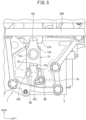
- Fig. 5 is a view showing a vehicle transmission according to a second embodiment of this invention, the same numbers are given to the same configurations as in the first embodiment, and the description thereof is omitted.
- a protrusion portion 2d is formed in the guide wall 2B.
- the protrusion portion 2d protrudes from the guide wall 2B toward the interlock plate 12 and extends in the up and down direction along the axis O of the shift/select shaft 5.
- the protrusion portion 2d enters between the left front wall 12C and the right front wall 12D and the interlock plate 12 is movable along the protrusion portion 2d.
- a groove portion 12c is formed in the interlock plate 12 by the left front wall 12C and the right front wall 12D and the groove portion 12c extends along the insertion direction of the shift/select shaft 5.
- the protrusion portion 2d of this embodiment constitutes the guide portion.
- the interlock plate 12 includes the groove portion 12c which extends along the insertion direction of the shift/select shaft 5 and the protrusion portion 2d enters the groove portion 12c before the shift/select shaft 5 engages with the engagement portion 2A when the shift/select shaft 5 is inserted into the transmission case 2 through the opening portion 2a.
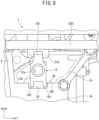
- Fig. 6 is a view showing a vehicle transmission according to a third embodiment of this invention, the same numbers are given to the same configurations as in the first embodiment, and the description thereof is omitted.
- a groove portion 2E is formed in the front wall 2W of the transmission case 2 facing the interlock plate 12 and the groove portion 2E extends in the up and down direction along the axis O of the shift/select shaft 5 between the opening portion 2a and the engagement portion 2A in the up and down direction.
- the groove portion 2E of this embodiment constitutes the guide portion.
- the left front wall 12C and the right front wall 12D are inserted into the groove portion 2E and the groove portion 2E sandwiches the left front wall 12C and the right front wall 12D from both left and right sides before the shift/select shaft 5 engages with the engagement portion 2A when the shift/select shaft 5 is inserted into the transmission case 2 through the opening portion 2a.
- the left front wall 12C and the right front wall 12D of this embodiment constitute a convex portion protruding from the interlock plate 12 toward the front wall 2W of the transmission case.
- the shift/select shaft 5 includes the left front wall 12C and the right front wall 12D protruding from the shift/select shaft 5 toward the front wall 2W of the transmission case 2 and the groove portion 2E sandwiches the left front wall 12C and the right front wall 12D from both left and right sides before the shift/select shaft 5 engages with the engagement portion 2A when the shift/select shaft 5 is inserted into the transmission case 2 through the opening portion 2a.
- the transmission 1 of this embodiment is composed of the AMT, but the transmission 1 may be composed of a MT (Manual Transmission).
- the interlock plate which comes into contact with the guide portion to be the second engagement is exemplified as the insertion component, but this invention is not limited thereto.
- the insertion component may be composed of a plurality of components. That is, the contact of the guide portion and the second engagement may be achieved by one insertion component and the insertion component coming into contact with the guide portion and the second engagement may be achieved by different insertion components.
Landscapes
- Engineering & Computer Science (AREA)
- General Engineering & Computer Science (AREA)
- Mechanical Engineering (AREA)
- Gear-Shifting Mechanisms (AREA)
Abstract
Description
- This invention relates to a vehicle transmission.
- A vehicle transmission is known in which insertion members such as an input shaft and an output shaft are held on the same line and assembled to a transmission case (see
JP H11-303952 A - In the vehicle transmission, a tip of the output shaft is inserted into a bearing hole provided in the input shaft and a pilot bearing is sandwiched therebetween to hold both shafts on the same axis. A guide pipe slidably and rotatably inserted into a guide hole provided at the tip of the output shaft is provided at the center of the bearing hole.
- A tip of the guide pipe is located closer to the output shaft than an outer end of the pilot bearing and both shafts are positioned by the guide pipe and the guide hole. Then, the tip of the output shaft is allowed to enter the bearing hole.
- [Patent Literature 1]
JP H11-303952 A - However, in the vehicle transmission described in
Patent Literature 1, the tip of the output shaft is allowed to enter the bearing hole after both shafts are positioned by the guide pipe and the guide hole, but in a state before the guide pipe enters the guide hole, the input shaft and the output shaft cannot be positioned on the same axis. - Therefore, an operator still needs to rely on intuition to position the guide pipe and the output shaft on the same axis and the work of assembling the input shaft and the output shaft to the transmission case becomes troublesome.
- Further, since the guide pipe and the guide hole described in
Patent Literature 1 cannot position the input shaft and the output shaft in the rotation direction, it is difficult to stabilize the posture at a desired position in the rotation direction and to assemble the input shaft and the output shaft into the transmission case. - This invention has been made in view of the above-described circumstances and an object of this invention is to provide a vehicle transmission capable of regulating a change in posture of an insertion member when the insertion member is inserted into a transmission case and improving an assembly property of the insertion member with respect to the transmission case.
- According to aspects of this invention, there is provided a vehicle transmission including: a transmission case having an opening portion; and an insertion member inserted into the transmission case through the opening portion, in which the transmission case includes at least one engagement portion provided inside the transmission case and engaging with the insertion member and a guide portion provided inside the transmission case to be located closer to the opening portion than the engagement portion, and in which a change in posture of the insertion member is regulated in such a manner that the insertion member comes into contact with the guide portion before the insertion member engages with the engagement portion when the insertion member is inserted into the transmission case through the opening portion.
- In this way, according to this invention, it is possible to regulate a change in posture of an insertion member when the insertion member is inserted into a transmission case and to improve an assembly property of the insertion member with respect to the transmission case.
- The vehicle transmission may also comprise the following features, taken alone or in combination:
- A gap is formed between the insertion member and the guide portion while the insertion member is assembled to the transmission case in a normal posture.
- The insertion direction of the insertion member is a direction along an axis of the insertion member.
- The insertion member includes a shaft member extending in an insertion direction.
- The insertion member includes a groove portion extending along the insertion direction of the insertion member, and
- The insertion member includes a convex portion protruding from the insertion member toward a wall portion of the transmission case, and
- The insertion member has a plane extending along the insertion direction of the insertion member, and
- The engagement portion is provided in the transmission case and an end portion of the insertion member enters therein to be first engagement.
- The insertion member includes an insertion component supported to be rotatable about an axis, and
- A lower end portion of the guide portion and an upper end portion of the engagement portion are located at the same height position.
-
- [
Fig. 1] Fig. 1 is a longitudinal sectional view in which a vehicle transmission according to a first embodiment of this invention is cut along an axis of a shift/select shaft. - [
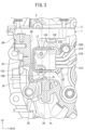
Fig. 2] Fig. 2 is a plan view of a transmission case in the periphery of an opening portion showing a relationship with an interlock plate, as a figure showing the vehicle transmission according to the first embodiment of this invention. - [
Fig. 3] Fig. 3 is a cross-sectional view when viewed from a direction III-III ofFig. 2 . - [
Fig. 4] Fig. 4 is a view showing a state in the middle of assembly in which the shift/select shaft is inserted into the transmission case through the opening portion, as a figure showing the vehicle transmission according to the first embodiment of this invention. - [
Fig. 5] Fig. 5 is a plan view of a transmission case in the periphery of an opening portion showing a relationship with an interlock plate, as a figure showing a vehicle transmission according to a second embodiment of this invention. - [
Fig. 6] Fig. 6 is a plan view of a transmission case in the periphery of an opening portion showing a relationship with an interlock plate, as a figure showing a vehicle transmission according to a third embodiment of this invention. - A vehicle transmission according to embodiments of this invention includes: a transmission case having an opening portion; and an insertion member inserted into the transmission case through the opening portion, in which the transmission case includes at least one engagement portion provided inside the transmission case and engaging with the insertion member and a guide portion provided inside the transmission case to be located closer to the opening portion than the engagement portion, and in which a change in posture of the insertion member is regulated in such a manner that the insertion member comes into contact with the guide portion before the insertion member engages with the engagement portion when the insertion member is inserted into the transmission case through the opening portion.
- Accordingly, the vehicle transmission according to embodiments of this invention can regulate a change in posture of the insertion member when the insertion member is inserted into the transmission case and improve the assembly property of the insertion member with respect to the transmission case.
- Hereinafter, a vehicle transmission according to embodiments of this invention will be described with reference to the drawings.
-
Figs. 1 to 4 are views showing a vehicle transmission according to a first embodiment of this invention. - In
Figs. 1 to 4 , the up, down, front, rear, left, and right directions are based on the vehicle transmission installed in the vehicle, the front and rear direction of the vehicle is the front and rear direction, the left and right direction of the vehicle (vehicle width direction) is the left and right direction, and the up and down direction of the vehicle (the height direction of the vehicle) is the up and down direction. - First, a configuration will be described.
- A
transmission 1 mounted on a vehicle is composed of, for example, an AMT (Automated Manual Transmission), converts a rotation speed and a rotation torque of an internal combustion engine (not shown) in response to a vehicle travel state, and transmits them to drive wheels (not shown). - A
transmission 1 includes atransmission case 2 and anopening portion 2a is formed at an upper portion of thetransmission case 2. Thetransmission case 2 is provided with components constituting thetransmission 1 such as ashift device 3 and a speed change gear mechanism (not shown). - The
shift device 3 includes a shift case 4 and the shift case 4 includes a cylindrical accommodation portion 4A and afixing portion 4B fixed to the upper portion of thetransmission case 2 by a bolt (not shown). - The shift case 4 closes the
opening portion 2a of thetransmission case 2 and thefixing portion 4B is fixed to the circumferential edge of theopening portion 2a by a bolt. - The shift case 4 is attached to the
transmission case 2 through a seal member (not shown) and theopening portion 2a of thetransmission case 2 is hermetically closed by the seal member. Accordingly, foreign matter is prevented from entering thetransmission case 2 through theopening portion 2a and lubricating oil stored inside thetransmission case 2 is prevented from leaking to the outside. - A shift/
select shaft 5 is accommodated inside thetransmission case 2. The upper portion of the shift/select shaft 5 is supported by the shift case 4. The shift/select shaft 5 is an insertion component which constitutes an insertion member inserted through theopening portion 2a of thetransmission case 2 and disposed and attached inside thetransmission case 2. - The shift/
select shaft 5 moves in the direction of the axis O with respect to the shift case 4 in accordance with a select operation and rotates around the axis O with respect to the shift case 4 in accordance with a shift operation. Additionally, the insertion member is an assembly of the shift/select shaft 5 and a component attached to the shift/select shaft 5 and is a portion inserted from theopening portion 2a into thetransmission case 2. Further, the insertion component is a component constituting the insertion member. - The axis of the shift/
select shaft 5 is indicated by O. Additionally, the direction of the axis O of the shift/select shaft 5 is also referred to as the axial direction of the shift/select shaft 5. - In
Fig. 1 , the movement of the shift/select shaft 5 in the axial direction is indicated by a select direction S1 and the rotation of the shift/select shaft 5 around the axis O is indicated by a shift direction S2. - The upper end side of the shift/
select shaft 5 is supported by the accommodation portion 4A of the shift case 4 and the shift/select shaft 5 is supported by the accommodation portion 4A to be axially movable and rotatable. - An
engagement portion 2A consisting of a hole into which alower end portion 5a of the shift/select shaft 5 is inserted is provided below theopening portion 2a of thetransmission case 2 and the shift/select shaft 5 is supported by theengagement portion 2A to be axially movable and rotatable. Hereinafter, the engagement position between thelower end portion 5a of the shift/select shaft 5 and theengagement portion 2A may be referred to as a "first engagement portion". - Further, the engagement of the
lower end portion 5a of the shift/select shaft 5 with respect to theengagement portion 2A is referred to as first engagement. Further, thelower end portion 5a of the shift/select shaft 5 constitutes the end portion of the insertion member. - That is, the
lower end portion 5a of the shift/select shaft 5 is supported at the first engagement portion by the shift case 4 and thetransmission case 2 to be axially movable and rotatable around the axis O. - The shift case 4 is provided with a select actuator and a shift actuator (not shown) and the select actuator and the shift actuator operate the shift/
select shaft 5 in the select direction S1 or the shift direction S2. - A
cam member 11 is fixed to the shift/select shaft 5 and thecam member 11 moves together with the shift/select shaft 5. - The
cam member 11 includes acam surface 11A, afinger portion 11B which protrudes in a direction orthogonal to the axial direction of the shift/select shaft 5 from a surface opposite to thecam surface 11A, and a guide groove (not shown) which is formed on a surface orthogonal to thecam surface 11A. - A first-speed/second-speed
stage shift yoke 21A, a third-speed/fourth-speedstage shift yoke 21B, a fifth-speed/sixth-speedstage shift yoke 21C, and abackward shift yoke 21D are arranged in thetransmission 1 in an overlapping manner. - The
finger portion 11B is fitted to any one of the first-speed/second-speedstage shift yoke 21A, the third-speed/fourth-speedstage shift yoke 21B, the fifth-speed/sixth-speedstage shift yoke 21C, and thebackward shift yoke 21D and swings about the axis O of the shift/select shaft 5 so that any one of the shift yokes 21A, 21B, 21C, and 21D is moved by the swing of thefinger portion 11B. - The shift yokes 21A, 21B, 21C, and 21D are formed in a U shape in the top plan view and are fitted to the
finger portion 11B to sandwich thefinger portion 11B in the left and right direction. - That is,
notch grooves select shaft 5 and thefinger portion 11B enters thenotch grooves finger portion 11B and the shift yokes 21A, 21B, 21C, and 21D are fitted to each other. Thetransmission 1 of this embodiment is a transmission with six forward speed stages. Additionally, the gear stage is not limited to the six speed stages. - An
interlock plate 12 is attached to the lower portion of the shift/select shaft 5 to surround thecam member 11. Since the shift/select shaft 5 is disposed to penetrate theinterlock plate 12 and cannot move in the axial direction of the shift/select shaft 5 by thecam member 11 disposed therein, theinterlock plate 12 moves in the axial direction together with the shift/select shaft 5 and rotates relative to the shift/select shaft 5. - In the
interlock plate 12, anupper wall 12A and alower wall 12B allowing the perpendicular penetration of the shift/select shaft 5 disposed inside thetransmission case 2 to be vertical to the axis O extend in the horizontal direction and the horizontal width of theinterlock plate 12 is formed to be longer than the diameter of the shift/select shaft 5. - As shown in
Figs. 1 and2 , theinterlock plate 12 includes theupper wall 12A, thelower wall 12B, a leftfront wall 12C (seeFig. 3 ) which connects the left front end portion of theupper wall 12A and the left front end portion of thelower wall 12B and extends in the up and down direction, a rightfront wall 12D which connects the right front end portion of theupper wall 12A and the right front end portion of thelower wall 12B and extends in the up and down direction, an upperrear wall 12E which is bent downward from the rear end portion of theupper wall 12A and extends toward thefinger portion 11B, and a lowerrear wall 12F which is bent upward from the rear end portion of thelower wall 12B and extends toward thefinger portion 11B. - Then, the
finger portion 11B is disposed in a slit 12d between the upper end of the lowerrear wall 12F and the lower end of the upperrear wall 12E disposed to face each other. Further, the upperrear wall 12E, the lowerrear wall 12F, and thefinger portion 11B are arranged in thenotch grooves Fig. 1 ) of the shift yokes 21A, 21B, 21C, and 21D in an assembled state of the shift/select shaft 5. - That is, the upper
rear wall 12E and the lowerrear wall 12F of theinterlock plate 12 engage with thenotch grooves rear wall 12F of theinterlock plate 12 and thenotch groove 21d of the shift yoke may be referred to as a "second engagement portion". - That is, the lower
rear wall 12F of theinterlock plate 12 is a portion which first engages with the notch groove of the shift yoke, thenotch groove 21d of the shift yoke is a portion which is located closest to theopening portion 2a and first engages with theinterlock plate 12, and the first engagement position of theinterlock plate 12 with respect to the shift yokes 21A, 21B, 21C, and 21D is referred to as a "second engagement portion". - Further, the engagement of the
interlock plate 12 with respect to the shift yokes 21A, 21B, 21C, and 21D is referred to as a second engagement. - As shown in
Fig. 2 , the leftfront wall 12C and the rightfront wall 12D are separated from each other in the left and right direction and are arranged side by side in the left and right direction. Specifically, the leftfront wall 12C and the rightfront wall 12D are arranged separately on the right side and the left side with respect to the shift/select shaft 5 and are arranged at substantially the same distance from the shift/select shaft 5 in the left and right direction. - Further, in a state in which the shift/
select shaft 5 is assembled to thetransmission case 2, adetent member 13 to be described later is inserted and disposed between the leftfront wall 12C and the rightfront wall 12D and thedetent member 13 comes into contact with the leftfront wall 12C or the rightfront wall 12D to regulate the position of theinterlock plate 12 in the rotation direction. - As shown in
Fig. 1 , through-holes upper wall 12A and thelower wall 12B and the shift/select shaft 5 is inserted through the through-holes - The slit 12d (see
Fig. 4 ) which extends in the horizontal direction is formed between the upperrear wall 12E and the lowerrear wall 12F of theinterlock plate 12. The tip of thefinger portion 11B protrudes toward the outside of theinterlock plate 12 through the slit 12d and thefinger portion 11B is fitted to any one of the shift yokes 21A, 21B, 21C, and 21D. - When the
finger portion 11B is fitted to any one of the shift yokes 21A, 21B, 21C, and 21D, the other three of the shift yokes 21A, 21B, 21C, and 21D engage with the upperrear wall 12E and the lowerrear wall 12F of theinterlock plate 12 and not fitted to thefinger portion 11B. - That is, three shift yokes not fitted to the
finger portion 11B among the shift yokes 21A, 21B, 21C, and 21D are maintained at a neutral position while engaging with the upperrear wall 12E or the lowerrear wall 12F of theinterlock plate 12 which is located at a position deviating from the slit 12d in the axial direction of the shift/select shaft 5 and is regulated in the rotational position by thedetent member 13. Accordingly, it is possible to prevent two speed stages from being achieved simultaneously within the transmission. - The
shift device 3 selects one shift yoke fitted to thefinger portion 11B when the shift/select shaft 5 moves in the select direction S1. - Then, when the shift/
select shaft 5 rotates in the shift direction S2, a shift fork (not shown) connected to one shift yoke fitted to thefinger portion 11B of thecam member 11 operates a synchronizer (not shown) so that a gear pair constituting an arbitrary gear stage is connected to be able to transmit power and the shift range is switched, that is, the gear is changed. - In
Fig. 1 , theshift yoke 21A is connected to the first-speed/second-speedstage shift shaft 22A and the first-speed/second-speed stage shift fork is connected to the first-speed/second-speedstage shift shaft 22A. - The
shift yoke 21B is connected to the third-speed/fourth-speedstage shift shaft 22B and the third-speed/fourth-speed stage shift fork is connected to the third-speed/fourth-speedstage shift shaft 22B. - The
shift yoke 21C is connected to the fifth-speed/sixth-speedstage shift shaft 22C and the fifth-speed/sixth-speed stage shift fork is connected to the fifth-speed/sixth-speedstage shift shaft 22C. - The
shift yoke 21D is connected to thebackward shift shaft 22D and the backward shift fork is connected to thebackward shift shaft 22D. - The upper and lower surfaces of the
cam member 11 contact theupper wall 12A and thelower wall 12B of theinterlock plate 12 and theinterlock plate 12 does not move relatively in the axial direction of the shift/select shaft 5. - A guide groove (not shown) formed on the outer peripheral surface of the
cam member 11 is composed of a plurality of shift gate patterns arranged at the same pattern as the shift pattern and a guide pin (not shown) is inserted into the guide groove. - As the shift/
select shaft 5 moves in theselect direction S 1 and rotates in the shift direction S2, the guide groove moves. At this time, since the guide pin is inserted into the guide groove, the guide groove (cam member 11) moves while being regulated by the guide pin and the guide pin comes into contact with the wall surface of the guide groove after the shift ends (the gear shift ends). - Accordingly, the movement amount of the shift/
select shaft 5 in the select direction S1 and the shift direction S2 is regulated and the rattling or unnecessary movement of the shift/select shaft 5 in the select direction S1 and the shift direction S2 is prevented. - A
guide wall 2B is formed in afront wall 2W of thetransmission case 2 facing thecam surface 11A of thecam member 11 and aboss portion 2C is provided in theguide wall 2B. The shift/select shaft 5 of this embodiment constitutes the shaft member, the shift/select shaft 5 and theinterlock plate 12 constitute the insertion member, and theinterlock plate 12 is the insertion member and constitutes the insertion component. - Further, the
front wall 2W of thetransmission case 2 constitutes the wall portion. That is, the insertion member is an assembly of the shift/select shaft 5 and the insertion component attached to the shift/select shaft 5 and is a portion inserted from theopening portion 2a and disposed inside thetransmission case 2. - The
detent member 13 is attached to theboss portion 2C. Thedetent member 13 includes atubular body 13A which is attached to theboss portion 2C, amovable body 13B which is accommodated in thetubular body 13A, and a coil spring (not shown) which is accommodated in thetubular body 13A and presses themovable body 13B against thecam surface 11A. - The tip of the
tubular body 13A of thedetent member 13 is disposed to be sandwiched between the leftfront wall 12C and the rightfront wall 12D and is fitted to the slit between the leftfront wall 12C and the rightfront wall 12D. - The
movable body 13B is located behind the leftfront wall 12C and the rightfront wall 12D and contacts thecam surface 11A. - The
detent member 13 applies an operation force when the shift/select shaft 5 moves in the select direction S1 and the shift direction S2 in such a manner that the coil spring generates a pressing force that presses themovable body 13B against thecam surface 11A when thecam member 11 moves in the select direction S1 and the shift direction S2. - When the shift/
select shaft 5 moves in the up and down direction, theinterlock plate 12 moves in the up and down direction while the leftfront wall 12C and the rightfront wall 12D are regulated by thetubular body 13A. Accordingly, theinterlock plate 12 is positioned in the rotation direction by thetubular body 13A to regulate the rotation of theinterlock plate 12. - The
guide wall 2B is located above theengagement portion 2A and is located below theopening portion 2a. That is, theguide wall 2B is located between the openingportion 2a and theengagement portion 2A in the up and down direction. - The
guide wall 2B is composed of a plane extending along the axis O of the shift/select shaft 5 and alower end portion 2b of theguide wall 2B is connected to anupper end portion 2c of theengagement portion 2A via alateral wall 2D. Theguide wall 2B of this embodiment constitutes the guide portion and thelower end portion 2b of theguide wall 2B constitutes the lower end portion of the guide portion. - That is, the
lower end portion 2b of theguide wall 2B and theupper end portion 2c of theengagement portion 2A are located at the same height position. - The left
front wall 12C and the rightfront wall 12D of theinterlock plate 12 facing theguide wall 2B are formed by planes parallel to the axis O of the shift/select shaft 5. That is, the leftfront wall 12C and the rightfront wall 12D of theinterlock plate 12 are formed by planes parallel to the insertion direction of the shift/select shaft 5. - In a state in which the shift/
select shaft 5 engages with theengagement portion 2A, a gap s is formed between theguide wall 2B and the leftfront wall 12C and the rightfront wall 12D of theinterlock plate 12 of the shift/select shaft 5. That is, in a state in which the shift/select shaft 5 is attached to thetransmission case 2, the insertion member does not come into contact with the guide portion and theinterlock plate 12 which is the insertion component constituting the insertion member is separated from theguide wall 2B. - The
guide wall 2B and the leftfront wall 12C and the rightfront wall 12D of theinterlock plate 12 are formed on substantially parallel surfaces and as for the gap s (horizontal distance), the gap s below thedetent member 13 is smaller than the gap s above thedetent member 13. - That is, the
guide wall 2B above thedetent member 13 is slightly separated forward from the shift/select shaft 5 than theguide wall 2B below thedetent member 13. - In the
transmission 1, since theguide wall 2B comes into contact with theinterlock plate 12 before theinterlock plate 12 reaches the shift yokes 21A, 21B, 21C, and 21D (before the second engagement portion engages to be the second engagement) when the shift/select shaft 5 and theinterlock plate 12 are inserted into thetransmission case 2 along the up and down direction through theopening portion 2a, a change in posture of the shift/select shaft 5 and theinterlock plate 12 is regulated. - Further, since the
guide wall 2B comes into contact with theinterlock plate 12 before the shift/select shaft 5 engages with theengagement portion 2A (before the first engagement portion engages to be the first engagement), a change in posture of the shift/select shaft 5 and theinterlock plate 12 is regulated. - Then, the
interlock plate 12 is smoothly inserted into thenotch grooves select shaft 5 is inserted into theengagement portion 2A ("first engagement portion"). - The posture of the shift/
select shaft 5 and theinterlock plate 12 means the directions (tilts) and rotational positions of the shift/select shaft 5 and theinterlock plate 12. - Further, the regulation of the change in posture of the shift/
select shaft 5 and theinterlock plate 12 means the regulation of the deviation from the normal position of the rotational position or the direction of the shift/select shaft 5 and theinterlock plate 12. - Further, the regulation also means that the shift/
select shaft 5 or theinterlock plate 12 deviating from the normal position can be adjusted to the normal position by the assembly operator using theguide wall 2B. - When the rotational positions or the directions of the shift/
select shaft 5 and theinterlock plate 12 are located at the normal positions, the upperrear wall 12E and the lowerrear wall 12F of theinterlock plate 12 are normally fitted to the shift yokes 21A, 21B, 21C, and 21D at the "second engagement portion" without the interference when assembling the shift/select shaft 5 and hence the assembly can be performed normally. - However, when the shift/
select shaft 5 does not take a normal posture and the shift/select shaft 5 is assembled to thetransmission case 2 while theinterlock plate 12 is tilted from the normal posture or rotated from the normal posture, the lowerrear wall 12F of theinterlock plate 12 interferes with the shift yokes 21A, 21B, 21C, and 21D and cannot enter thenotch grooves - Further, when the posture is not normal, the
lower end portion 5a of the shift/select shaft 5 cannot enter theengagement portion 2A and the "first engagement portion" may not engage normally. Accordingly, the normal assembly is difficult. - Next, an operation will be described.
- The shift case 4 is omitted in
Fig. 4 , but in the manufacturing process of thetransmission 1, the shift/select shaft 5 and theinterlock plate 12 which are integrated with each other are inserted into thetransmission case 2 through theopening portion 2a. At this time, the shift/select shaft 5 and the shift case 4 are integrated. - If the postures of the shift/
select shaft 5 and theinterlock plate 12 change (deviate from the normal postures) due to the tilting of the shift/select shaft 5 or the rotation of theinterlock plate 12 in the operation of inserting the shift/select shaft 5 and theinterlock plate 12 into thetransmission case 2 through theopening portion 2a and assembling them to thetransmission case 2, the upperrear wall 12E and the lowerrear wall 12F of theinterlock plate 12 do not enter thenotch grooves lower end portion 5a of the shift/select shaft 5 cannot enter theengagement portion 2A. - Since the
interlock plate 12 is rotatably assembled to the shift/select shaft 5 in a state before the assembly to thetransmission case 2, there is a possibility that theinterlock plate 12 may rotate with respect to the shift/select shaft 5 during the assembly of the shift/select shaft 5. - When the
interlock plate 12 rotates with respect to the shift/select shaft 5, the upperrear wall 12E and the lowerrear wall 12F of theinterlock plate 12 and thenotch grooves rear wall 12F of theinterlock plate 12 interferes with the shift yokes 21A, 21B, 21C, and 21D and cannot enter thenotch grooves rear wall 12F which is the lower end of theinterlock plate 12 and theshift yoke 21D closest to theopening portion 2a interfere with each other. - Therefore, when the
interlock plate 12 rotates with respect to the shift/select shaft 5, the operator separates the shift/select shaft 5 from thetransmission case 2 and tries to insert theinterlock plate 12 again after correcting the posture thereof. Accordingly, since it is necessary to repeat the assembly work of the shift/select shaft 5 several times, it takes much time and effort for assembling the shift/select shaft 5. As a result, the assembly workability of the shift/select shaft 5 deteriorates. - According to the
transmission 1 of this embodiment, thetransmission case 2 includes a second engagement portion (the engagement position of theinterlock plate 12 and the shift yokes 21A, 21B, 21C, and 21D) provided inside thetransmission case 2 and engaging with the insertion member or a first engagement portion (the engagement position of thelower end portion 5a of the shift/select shaft 5 with respect to theengagement portion 2A) engaging with the insertion member and theguide wall 2B which is provided inside thetransmission case 2 to be located closer to theopening portion 2a than the first engagement portion and the second engagement portion. - Then, the
guide wall 2B is disposed to be able to come into contact with theinterlock plate 12 before engaging with thenotch grooves guide wall 2B is formed on the inner surface of thetransmission case 2 to be able to come into contact with theinterlock plate 12 before thelower end portion 5a of the shift/select shaft 5 engages with theengagement portion 2A. - Then, in the
transmission 1 of this embodiment, when the shift/select shaft 5 having theinterlock plate 12 assembled thereto is inserted into thetransmission case 2 through theopening portion 2a, theinterlock plate 12 comes into contact with theguide wall 2B to regulate a change in posture of the shift/select shaft 5 and theinterlock plate 12 before the shift/select shaft 5 engages with the first engagement portion or the second engagement portion to be the first engagement and the second engagement. - That is, if the postures of the shift/
select shaft 5 and theinterlock plate 12 change when the shift/select shaft 5 and theinterlock plate 12 are inserted into thetransmission case 2 through theopening portion 2a, theinterlock plate 12 comes into contact with theguide wall 2B. - Accordingly, it is possible to regulate a change in posture of the shift/
select shaft 5 and theinterlock plate 12, to guide the lowerrear wall 12F of theinterlock plate 12 to thenotch grooves select shaft 5 to theengagement portion 2A in a normal posture. - That is, the operator can stabilize the postures and the positions of the shift/
select shaft 5 and theinterlock plate 12 by bringing theinterlock plate 12 into contact with theguide wall 2B and the operator can correct the posture of the interlock plate 12 (the direction in the rotation direction) by bringing theinterlock plate 12 into contact with theguide wall 2B. Accordingly, it is possible to remarkably improve the assembly workability. -
Fig. 2 shows a state in which the upperrear wall 12E of theinterlock plate 12 normally enters thenotch groove 21d of theshift yoke 21D and in this state, thenotch grooves rear wall 12E and the lowerrear wall 12F of theinterlock plate 12. - Since the upper portion of the engagement portion is covered and hidden by the shift case 4 in the assembly work, the operator cannot easily check the engagement portion. However, the
guide wall 2B and the leftfront wall 12C and the rightfront wall 12D of theinterlock plate 12 arranged in front of the operator can be relatively easily checked by the operator and the positions of the shift/select shaft 5 and theinterlock plate 12 can be adjusted. - That is, according to the
transmission 1 of this embodiment, thelower end portion 5a of the shift/select shaft 5 is provided in thetransmission case 2 and thelower end portion 5a of the shift/select shaft 5 enters to be the first engagement. - Further, according to the
transmission 1 of this embodiment, theinterlock plate 12 is installed inside thetransmission case 2 and theinterlock plate 12 enters to be the second engagement. - In this way, in the
transmission 1 of this embodiment, it is possible to regulate a change in direction or rotational posture of the shift/select shaft 5 and theinterlock plate 12 by using theguide wall 2B provided in thetransmission case 2 and to improve the assembly workability of the shift/select shaft 5 with respect to thetransmission case 2. - As a result, it is possible to improve the reliability of the
transmission 1 by normally fitting thefinger portion 11B to the desired shift yokes 21A, 21B, 21C, and 21D at the time of shifting. - Additionally, the
detent member 13 is attached to theboss portion 2C while the shift/select shaft 5 is attached to theengagement portion 2A and theinterlock plate 12 takes a normal attachment posture not to contact theguide wall 2B. - Further, since the upper end of the
guide wall 2B is formed closer to theopening portion 2a than the dimension of theinterlock plate 12 in the up and down direction, the operator can check the contact state between theinterlock plate 12 and theguide wall 2B from above at a visual check position while the shift/select shaft 5 is inserted into thetransmission case 2 through theopening portion 2a. - Further, since the operator can easily correct the direction by bringing the
interlock plate 12 into contact with theguide wall 2B when a problem is found in the direction or rotational posture of theinterlock plate 12, it is possible to more effectively improve the assembly property of the shift/select shaft 5 to thetransmission case 2. - Further, according to the
transmission 1 of this embodiment, theguide wall 2B above thedetent member 13 is slightly separated forward from the shift/select shaft 5 than theguide wall 2B below thedetent member 13. - Accordingly, as the shift/
select shaft 5 moves toward theengagement portion 2A, theinterlock plate 12 can be moved toward theengagement portion 2A along theguide wall 2B and the axis O of the shift/select shaft 5 can easily match the center axis of theengagement portion 2A. Therefore, it is possible to smoothly insert the shift/select shaft 5 into theengagement portion 2A. - Further, according to the
transmission 1 of this embodiment, the insertion direction of the shift/select shaft 5 is the direction along the axis O of the shift/select shaft 5. That is, the insertion direction is the vertical direction, which is easy for the operator to understand, and can improve workability. - When the
engagement portion 2A engages with the shift/select shaft 5, the shift/select shaft 5 is supported to be rotatable about the axis O. Then, theguide wall 2B comes into contact with theinterlock plate 12 to regulate a change in rotation position of theinterlock plate 12. - In this way, it is possible to regulate a change in rotational posture of the shift/
select shaft 5 and theinterlock plate 12 by using theguide wall 2B provided in thetransmission case 2 even when the shift/select shaft 5 is rotatably supported by theengagement portion 2A and to improve the assembly workability of the shift/select shaft 5 with respect to thetransmission case 2. - Further, according to the
transmission 1 of this embodiment, since the shift/select shaft 5 is composed of the shaft member extending in the insertion direction, it is necessary to move the shift/select shaft 5 in the up and down direction over a long distance until the shift/select shaft 5 is inserted into thetransmission case 2 from theopening portion 2a and is engaged with theengagement portion 2A. - In the
transmission 1 of this embodiment, since theinterlock plate 12 comes into contact with theguide wall 2B before the shift/select shaft 5 engages with theengagement portion 2A when the shift/select shaft 5 having theinterlock plate 12 assembled thereto is inserted into thetransmission case 2 through theopening portion 2a, a change in posture of the shift/select shaft 5 and theinterlock plate 12 is regulated. - Accordingly, it is possible to reliably regulate a change in posture of the
interlock plate 12 attached to the elongated shift/select shaft 5. - Further, according to the
transmission 1 of this embodiment, since thelower end portion 2b of theguide wall 2B and theupper end portion 2c of theengagement portion 2A are located at the same height position, theinterlock plate 12 can be guided to the vicinity of theengagement portion 2A along theguide wall 2B when the shift/select shaft 5 is inserted into thetransmission case 2 through theopening portion 2a. - Therefore, it is possible to more effectively regulate a change in posture of the shift/
select shaft 5 and theinterlock plate 12. - Further, according to the
transmission 1 of this embodiment, the leftfront wall 12C and the rightfront wall 12D of theinterlock plate 12 have planes extending along the insertion direction of the shift/select shaft 5 and theguide wall 2B is composed of a plane extending in parallel to the leftfront wall 12C and the rightfront wall 12D. - Accordingly, it is possible to more effectively regulate the postures of the shift/
select shaft 5 and theinterlock plate 12 by the surface contact of the leftfront wall 12C and the rightfront wall 12D of theinterlock plate 12 with respect to theguide wall 2B when the shift/select shaft 5 and theinterlock plate 12 are inserted into thetransmission case 2 through theopening portion 2a. - As a result, it is possible to more effectively improve the assembly property of the shift/
select shaft 5 to thetransmission case 2. -
Fig. 5 is a view showing a vehicle transmission according to a second embodiment of this invention, the same numbers are given to the same configurations as in the first embodiment, and the description thereof is omitted. - As shown in
Fig. 5 , aprotrusion portion 2d is formed in theguide wall 2B. Theprotrusion portion 2d protrudes from theguide wall 2B toward theinterlock plate 12 and extends in the up and down direction along the axis O of the shift/select shaft 5. - The
protrusion portion 2d enters between the leftfront wall 12C and the rightfront wall 12D and theinterlock plate 12 is movable along theprotrusion portion 2d. - That is, a
groove portion 12c is formed in theinterlock plate 12 by the leftfront wall 12C and the rightfront wall 12D and thegroove portion 12c extends along the insertion direction of the shift/select shaft 5. Theprotrusion portion 2d of this embodiment constitutes the guide portion. - According to the
transmission 1 of this embodiment, theinterlock plate 12 includes thegroove portion 12c which extends along the insertion direction of the shift/select shaft 5 and theprotrusion portion 2d enters thegroove portion 12c before the shift/select shaft 5 engages with theengagement portion 2A when the shift/select shaft 5 is inserted into thetransmission case 2 through theopening portion 2a. - That is, since the
protrusion portion 2d enters thegroove portion 12c of theinterlock plate 12 before the shift/select shaft 5 engages with the first engagement portion or the second engagement portion to be the first engagement and the second engagement, it is possible to regulate a change in position or posture of the shift/select shaft 5 and theinterlock plate 12. - Accordingly, it is possible to regulate a change in direction or rotational posture of the shift/
select shaft 5 and theinterlock plate 12 and to improve the assembly workability of the shift/select shaft 5 with respect to thetransmission case 2. - Further, since it is possible to guide the shift/
select shaft 5 to theengagement portion 2A while theprotrusion portion 2d enters thegroove portion 12c, it is possible to more effectively improve the assembly property of the shift/select shaft 5 to thetransmission case 2. -
Fig. 6 is a view showing a vehicle transmission according to a third embodiment of this invention, the same numbers are given to the same configurations as in the first embodiment, and the description thereof is omitted. - A
groove portion 2E is formed in thefront wall 2W of thetransmission case 2 facing theinterlock plate 12 and thegroove portion 2E extends in the up and down direction along the axis O of the shift/select shaft 5 between the openingportion 2a and theengagement portion 2A in the up and down direction. Thegroove portion 2E of this embodiment constitutes the guide portion. - The left
front wall 12C and the rightfront wall 12D are inserted into thegroove portion 2E and thegroove portion 2E sandwiches the leftfront wall 12C and the rightfront wall 12D from both left and right sides before the shift/select shaft 5 engages with theengagement portion 2A when the shift/select shaft 5 is inserted into thetransmission case 2 through theopening portion 2a. - The left
front wall 12C and the rightfront wall 12D of this embodiment constitute a convex portion protruding from theinterlock plate 12 toward thefront wall 2W of the transmission case. - According to the
transmission 1 of this embodiment, the shift/select shaft 5 includes the leftfront wall 12C and the rightfront wall 12D protruding from the shift/select shaft 5 toward thefront wall 2W of thetransmission case 2 and thegroove portion 2E sandwiches the leftfront wall 12C and the rightfront wall 12D from both left and right sides before the shift/select shaft 5 engages with theengagement portion 2A when the shift/select shaft 5 is inserted into thetransmission case 2 through theopening portion 2a. - That is, since the
groove portion 2E is sandwiched between the leftfront wall 12C and the rightfront wall 12D of theinterlock plate 12 before the shift/select shaft 5 engages with the first engagement portion or the second engagement portion to be the first engagement and the second engagement, it is possible to regulate a change in position or posture of the shift/select shaft 5 and theinterlock plate 12. - Accordingly, it is possible to regulate a change in direction or rotational posture of the shift/
select shaft 5 and theinterlock plate 12 and to improve the assembly workability of the shift/select shaft 5 with respect to thetransmission case 2. - Further, since it is possible to guide the shift/
select shaft 5 to theengagement portion 2A while the leftfront wall 12C and the rightfront wall 12D enter thegroove portion 2E, it is possible to more effectively improve the assembly property of the shift/select shaft 5 to thetransmission case 2. - The
transmission 1 of this embodiment is composed of the AMT, but thetransmission 1 may be composed of a MT (Manual Transmission). - Further, the interlock plate which comes into contact with the guide portion to be the second engagement is exemplified as the insertion component, but this invention is not limited thereto. For example, the insertion component may be composed of a plurality of components. That is, the contact of the guide portion and the second engagement may be achieved by one insertion component and the insertion component coming into contact with the guide portion and the second engagement may be achieved by different insertion components.
- While embodiments of this invention have been described, it is apparent that some artisan could have made changes without departing from the scope of this invention. It is intended that any and all such modifications and equivalents are involved in the appended claims.
- 1 ... Transmission (vehicle transmission), 2 ... Transmission case, 2A ... Engagement portion (engagement portion), 2a ... Opening portion, 2B ... Guide wall (guide portion), 2b ... Lower end portion (lower end portion of guide portion), 2c ... Upper end portion (upper end portion of engagement portion), 2d ... Protrusion portion (guide portion), 2E ... Groove portion (guide portion), 2W ... Front wall (wall portion), 5 ... Shift/select shaft (insertion member, shaft member), 5a ... Lower end portion (lower end portion of insertion member), 12 ... Interlock plate (insertion component), 12C ... Left front wall (convex portion), 12D ... Right front wall (convex portion), 21d ... Notch groove of shift yoke (engagement portion), s ... Gap
Claims (10)
- A vehicle transmission comprising:a transmission case having an opening portion; andan insertion member inserted into the transmission case through the opening portion,wherein the transmission case includes at least one engagement portion provided inside the transmission case and engaging with the insertion member and a guide portion provided inside the transmission case to be located closer to the opening portion than the engagement portion, andwherein a change in posture of the insertion member is regulated in such a manner that the insertion member comes into contact with the guide portion before the insertion member engages with the engagement portion when the insertion member is inserted into the transmission case through the opening portion.
- The vehicle transmission according to claim 1,
wherein a gap is formed between the insertion member and the guide portion while the insertion member is assembled to the transmission case in a normal posture. - The vehicle transmission according to claim 1 or 2,wherein the insertion direction of the insertion member is a direction along an axis of the insertion member,wherein the insertion member includes an insertion component supported to be rotatable about the axis, andwherein the insertion member comes into contact with the guide portion to regulate a change in rotational posture of the insertion component.
- The vehicle transmission according to any one of claims 1 to 3,
wherein the insertion member includes a shaft member extending in an insertion direction. - The vehicle transmission according to any one of claims 1 to 4,wherein the insertion member includes a groove portion extending along the insertion direction of the insertion member, andwherein the guide portion enters the groove portion before the insertion member engages with the engagement portion when the insertion member is inserted into the transmission case through the opening portion.
- The vehicle transmission according to any one of claims 1 to 4,wherein the insertion member includes a convex portion protruding from the insertion member toward a wall portion of the transmission case, andwherein the guide portion sandwiches the convex portion from both sides before the insertion member engages with the engagement portion when the insertion member is inserted into the transmission case through the opening portion.
- The vehicle transmission according to any one of claims 1 to 6,wherein the insertion member has a plane extending along the insertion direction of the insertion member, andwherein the guide portion is composed of a plane extending in parallel to the plane of the insertion member.
- The vehicle transmission according to any one of claims 1 to 7,
wherein the engagement portion is provided in the transmission case and an end portion of the insertion member enters therein to be first engagement. - The vehicle transmission according to any one of claims 1 to 7,wherein the insertion member includes an insertion component supported to be rotatable about an axis, andwherein the engagement portion is installed inside the transmission case and the insertion component enters therein to be second engagement.
- The vehicle transmission according to claim 8,
wherein a lower end portion of the guide portion and an upper end portion of the engagement portion are located at the same height position.
Applications Claiming Priority (1)
| Application Number | Priority Date | Filing Date | Title |
|---|---|---|---|
| JP2022016537A JP7779162B2 (en) | 2022-02-04 | 2022-02-04 | Vehicle transmission |
Publications (2)
| Publication Number | Publication Date |
|---|---|
| EP4224039A1 true EP4224039A1 (en) | 2023-08-09 |
| EP4224039B1 EP4224039B1 (en) | 2025-07-30 |
Family
ID=84980822
Family Applications (1)
| Application Number | Title | Priority Date | Filing Date |
|---|---|---|---|
| EP23151628.7A Active EP4224039B1 (en) | 2022-02-04 | 2023-01-13 | Vehicle transmission |
Country Status (3)
| Country | Link |
|---|---|
| EP (1) | EP4224039B1 (en) |
| JP (1) | JP7779162B2 (en) |
| HU (1) | HUE073062T2 (en) |
Citations (5)
| Publication number | Priority date | Publication date | Assignee | Title |
|---|---|---|---|---|
| JPH11303952A (en) | 1998-04-21 | 1999-11-02 | Hino Motors Ltd | Vehicular transmission |
| WO2013121278A1 (en) * | 2012-02-17 | 2013-08-22 | Kongsberg Automotive As | Shift select device for a transmission |
| JP2015081631A (en) * | 2013-10-22 | 2015-04-27 | スズキ株式会社 | Manual transmission shift device |
| DE102019006118A1 (en) * | 2018-08-31 | 2020-03-05 | Suzuki Motor Corporation | OIL GUTTER FOR TRANSMISSION |
| JP6786923B2 (en) * | 2016-07-14 | 2020-11-18 | スズキ株式会社 | Shift device |
Family Cites Families (2)
| Publication number | Priority date | Publication date | Assignee | Title |
|---|---|---|---|---|
| JPS57207921A (en) * | 1981-06-17 | 1982-12-20 | Toyota Motor Corp | Detent mechanism of speed changing operational mechanism of manual transmission |
| JP2010216603A (en) | 2009-03-18 | 2010-09-30 | Aisin Ai Co Ltd | Operation device of manual transmission |
-
2022
- 2022-02-04 JP JP2022016537A patent/JP7779162B2/en active Active
-
2023
- 2023-01-13 EP EP23151628.7A patent/EP4224039B1/en active Active
- 2023-01-13 HU HUE23151628A patent/HUE073062T2/en unknown
Patent Citations (5)
| Publication number | Priority date | Publication date | Assignee | Title |
|---|---|---|---|---|
| JPH11303952A (en) | 1998-04-21 | 1999-11-02 | Hino Motors Ltd | Vehicular transmission |
| WO2013121278A1 (en) * | 2012-02-17 | 2013-08-22 | Kongsberg Automotive As | Shift select device for a transmission |
| JP2015081631A (en) * | 2013-10-22 | 2015-04-27 | スズキ株式会社 | Manual transmission shift device |
| JP6786923B2 (en) * | 2016-07-14 | 2020-11-18 | スズキ株式会社 | Shift device |
| DE102019006118A1 (en) * | 2018-08-31 | 2020-03-05 | Suzuki Motor Corporation | OIL GUTTER FOR TRANSMISSION |
Also Published As
| Publication number | Publication date |
|---|---|
| JP7779162B2 (en) | 2025-12-03 |
| EP4224039B1 (en) | 2025-07-30 |
| HUE073062T2 (en) | 2025-12-28 |
| JP2023114266A (en) | 2023-08-17 |
Similar Documents
| Publication | Publication Date | Title |
|---|---|---|
| JP5146253B2 (en) | Manual transmission | |
| EP2203665B1 (en) | Adjustment mechanism for a speed-change cable of a manual transmission | |
| JP2013113305A (en) | Lubricating oil supply structure of gearbox | |
| EP4224039B1 (en) | Vehicle transmission | |
| US10066730B2 (en) | Gearbox and method for assembling same | |
| EP2085664A2 (en) | Operating mechanism of a manual transmission | |
| EP2090811A2 (en) | Gear noise preventing device for manual transmission | |
| JP6119591B2 (en) | Transmission operating device for transmission | |
| EP2107279A2 (en) | Gear whine prevention device for manual transmission | |
| JP2008232262A (en) | Shift operation device for transmission | |
| JP2018009646A (en) | Shift device | |
| JP6384402B2 (en) | Manual transmission shift device | |
| JP2018017373A (en) | Shaft Assembly | |
| JP6079609B2 (en) | Transmission operating device for transmission | |
| JP5543816B2 (en) | Transmission shift and select shaft assembly | |
| JP2010054016A (en) | Automatic transmission assembling structure | |
| JP6413849B2 (en) | Manual transmission shift device | |
| JP2005090621A (en) | Reverse gear shift prevention device for manual transmission | |
| EP2169280B1 (en) | Transmission and method for manufacturing same | |
| JP7746876B2 (en) | Vehicle transmission | |
| JP6471609B2 (en) | Manual transmission shift device | |
| US9874280B2 (en) | Manual transmission | |
| US20190195362A1 (en) | Interlock mechanism | |
| JP6304322B2 (en) | Transmission operating mechanism of transmission | |
| JP6361619B2 (en) | Transmission operating mechanism of transmission |
Legal Events
| Date | Code | Title | Description |
|---|---|---|---|
| PUAI | Public reference made under article 153(3) epc to a published international application that has entered the european phase |
Free format text: ORIGINAL CODE: 0009012 |
|
| STAA | Information on the status of an ep patent application or granted ep patent |
Free format text: STATUS: REQUEST FOR EXAMINATION WAS MADE |
|
| 17P | Request for examination filed |
Effective date: 20230113 |
|
| AK | Designated contracting states |
Kind code of ref document: A1 Designated state(s): AL AT BE BG CH CY CZ DE DK EE ES FI FR GB GR HR HU IE IS IT LI LT LU LV MC ME MK MT NL NO PL PT RO RS SE SI SK SM TR |
|
| STAA | Information on the status of an ep patent application or granted ep patent |
Free format text: STATUS: EXAMINATION IS IN PROGRESS |
|
| 17Q | First examination report despatched |
Effective date: 20240606 |
|
| GRAP | Despatch of communication of intention to grant a patent |
Free format text: ORIGINAL CODE: EPIDOSNIGR1 |
|
| STAA | Information on the status of an ep patent application or granted ep patent |
Free format text: STATUS: GRANT OF PATENT IS INTENDED |
|
| RIC1 | Information provided on ipc code assigned before grant |
Ipc: F16H 57/02 20120101ALN20250226BHEP Ipc: F16H 63/30 20060101ALN20250226BHEP Ipc: F16H 61/24 20060101ALI20250226BHEP Ipc: F16H 63/18 20060101AFI20250226BHEP |
|
| RIC1 | Information provided on ipc code assigned before grant |
Ipc: F16H 57/02 20120101ALN20250310BHEP Ipc: F16H 63/30 20060101ALN20250310BHEP Ipc: F16H 61/24 20060101ALI20250310BHEP Ipc: F16H 63/18 20060101AFI20250310BHEP |
|
| INTG | Intention to grant announced |
Effective date: 20250319 |
|
| GRAS | Grant fee paid |
Free format text: ORIGINAL CODE: EPIDOSNIGR3 |
|
| GRAA | (expected) grant |
Free format text: ORIGINAL CODE: 0009210 |
|
| STAA | Information on the status of an ep patent application or granted ep patent |
Free format text: STATUS: THE PATENT HAS BEEN GRANTED |
|
| AK | Designated contracting states |
Kind code of ref document: B1 Designated state(s): AL AT BE BG CH CY CZ DE DK EE ES FI FR GB GR HR HU IE IS IT LI LT LU LV MC ME MK MT NL NO PL PT RO RS SE SI SK SM TR |
|
| REG | Reference to a national code |
Ref country code: GB Ref legal event code: FG4D |
|
| REG | Reference to a national code |
Ref country code: CH Ref legal event code: EP |
|
| REG | Reference to a national code |
Ref country code: DE Ref legal event code: R096 Ref document number: 602023005087 Country of ref document: DE |
|
| REG | Reference to a national code |
Ref country code: IE Ref legal event code: FG4D |
|
| REG | Reference to a national code |
Ref country code: NL Ref legal event code: MP Effective date: 20250730 |
|
| REG | Reference to a national code |
Ref country code: AT Ref legal event code: MK05 Ref document number: 1819238 Country of ref document: AT Kind code of ref document: T Effective date: 20250730 |
|
| PG25 | Lapsed in a contracting state [announced via postgrant information from national office to epo] |
Ref country code: PT Free format text: LAPSE BECAUSE OF FAILURE TO SUBMIT A TRANSLATION OF THE DESCRIPTION OR TO PAY THE FEE WITHIN THE PRESCRIBED TIME-LIMIT Effective date: 20251202 |
|
| REG | Reference to a national code |
Ref country code: HU Ref legal event code: AG4A Ref document number: E073062 Country of ref document: HU |
|
| PG25 | Lapsed in a contracting state [announced via postgrant information from national office to epo] |
Ref country code: IS Free format text: LAPSE BECAUSE OF FAILURE TO SUBMIT A TRANSLATION OF THE DESCRIPTION OR TO PAY THE FEE WITHIN THE PRESCRIBED TIME-LIMIT Effective date: 20251130 |
|
| PG25 | Lapsed in a contracting state [announced via postgrant information from national office to epo] |
Ref country code: NO Free format text: LAPSE BECAUSE OF FAILURE TO SUBMIT A TRANSLATION OF THE DESCRIPTION OR TO PAY THE FEE WITHIN THE PRESCRIBED TIME-LIMIT Effective date: 20251030 |
|
| REG | Reference to a national code |
Ref country code: LT Ref legal event code: MG9D |
|
| PG25 | Lapsed in a contracting state [announced via postgrant information from national office to epo] |
Ref country code: AT Free format text: LAPSE BECAUSE OF FAILURE TO SUBMIT A TRANSLATION OF THE DESCRIPTION OR TO PAY THE FEE WITHIN THE PRESCRIBED TIME-LIMIT Effective date: 20250730 |
|
| PG25 | Lapsed in a contracting state [announced via postgrant information from national office to epo] |
Ref country code: FI Free format text: LAPSE BECAUSE OF FAILURE TO SUBMIT A TRANSLATION OF THE DESCRIPTION OR TO PAY THE FEE WITHIN THE PRESCRIBED TIME-LIMIT Effective date: 20250730 |
|
| PG25 | Lapsed in a contracting state [announced via postgrant information from national office to epo] |
Ref country code: HR Free format text: LAPSE BECAUSE OF FAILURE TO SUBMIT A TRANSLATION OF THE DESCRIPTION OR TO PAY THE FEE WITHIN THE PRESCRIBED TIME-LIMIT Effective date: 20250730 Ref country code: NL Free format text: LAPSE BECAUSE OF FAILURE TO SUBMIT A TRANSLATION OF THE DESCRIPTION OR TO PAY THE FEE WITHIN THE PRESCRIBED TIME-LIMIT Effective date: 20250730 |
|
| PGFP | Annual fee paid to national office [announced via postgrant information from national office to epo] |
Ref country code: FR Payment date: 20251114 Year of fee payment: 4 |
|
| PG25 | Lapsed in a contracting state [announced via postgrant information from national office to epo] |
Ref country code: GR Free format text: LAPSE BECAUSE OF FAILURE TO SUBMIT A TRANSLATION OF THE DESCRIPTION OR TO PAY THE FEE WITHIN THE PRESCRIBED TIME-LIMIT Effective date: 20251031 |
|
| PG25 | Lapsed in a contracting state [announced via postgrant information from national office to epo] |
Ref country code: SE Free format text: LAPSE BECAUSE OF FAILURE TO SUBMIT A TRANSLATION OF THE DESCRIPTION OR TO PAY THE FEE WITHIN THE PRESCRIBED TIME-LIMIT Effective date: 20250730 |
|
| PG25 | Lapsed in a contracting state [announced via postgrant information from national office to epo] |
Ref country code: LV Free format text: LAPSE BECAUSE OF FAILURE TO SUBMIT A TRANSLATION OF THE DESCRIPTION OR TO PAY THE FEE WITHIN THE PRESCRIBED TIME-LIMIT Effective date: 20250730 |
|
| PG25 | Lapsed in a contracting state [announced via postgrant information from national office to epo] |
Ref country code: BG Free format text: LAPSE BECAUSE OF FAILURE TO SUBMIT A TRANSLATION OF THE DESCRIPTION OR TO PAY THE FEE WITHIN THE PRESCRIBED TIME-LIMIT Effective date: 20250730 Ref country code: PL Free format text: LAPSE BECAUSE OF FAILURE TO SUBMIT A TRANSLATION OF THE DESCRIPTION OR TO PAY THE FEE WITHIN THE PRESCRIBED TIME-LIMIT Effective date: 20250730 |
|
| PG25 | Lapsed in a contracting state [announced via postgrant information from national office to epo] |
Ref country code: RS Free format text: LAPSE BECAUSE OF FAILURE TO SUBMIT A TRANSLATION OF THE DESCRIPTION OR TO PAY THE FEE WITHIN THE PRESCRIBED TIME-LIMIT Effective date: 20251030 |
|
| PG25 | Lapsed in a contracting state [announced via postgrant information from national office to epo] |
Ref country code: ES Free format text: LAPSE BECAUSE OF FAILURE TO SUBMIT A TRANSLATION OF THE DESCRIPTION OR TO PAY THE FEE WITHIN THE PRESCRIBED TIME-LIMIT Effective date: 20250730 |
|
| PGFP | Annual fee paid to national office [announced via postgrant information from national office to epo] |
Ref country code: HU Payment date: 20251223 Year of fee payment: 4 |
|
| PG25 | Lapsed in a contracting state [announced via postgrant information from national office to epo] |
Ref country code: SM Free format text: LAPSE BECAUSE OF FAILURE TO SUBMIT A TRANSLATION OF THE DESCRIPTION OR TO PAY THE FEE WITHIN THE PRESCRIBED TIME-LIMIT Effective date: 20250730 |
|
| PG25 | Lapsed in a contracting state [announced via postgrant information from national office to epo] |
Ref country code: DK Free format text: LAPSE BECAUSE OF FAILURE TO SUBMIT A TRANSLATION OF THE DESCRIPTION OR TO PAY THE FEE WITHIN THE PRESCRIBED TIME-LIMIT Effective date: 20250730 |
|
| PGFP | Annual fee paid to national office [announced via postgrant information from national office to epo] |
Ref country code: DE Payment date: 20260114 Year of fee payment: 4 |
|
| PG25 | Lapsed in a contracting state [announced via postgrant information from national office to epo] |
Ref country code: IT Free format text: LAPSE BECAUSE OF FAILURE TO SUBMIT A TRANSLATION OF THE DESCRIPTION OR TO PAY THE FEE WITHIN THE PRESCRIBED TIME-LIMIT Effective date: 20250730 |
|
| PG25 | Lapsed in a contracting state [announced via postgrant information from national office to epo] |
Ref country code: CZ Free format text: LAPSE BECAUSE OF FAILURE TO SUBMIT A TRANSLATION OF THE DESCRIPTION OR TO PAY THE FEE WITHIN THE PRESCRIBED TIME-LIMIT Effective date: 20250730 |
|
| PG25 | Lapsed in a contracting state [announced via postgrant information from national office to epo] |
Ref country code: EE Free format text: LAPSE BECAUSE OF FAILURE TO SUBMIT A TRANSLATION OF THE DESCRIPTION OR TO PAY THE FEE WITHIN THE PRESCRIBED TIME-LIMIT Effective date: 20250730 Ref country code: SK Free format text: LAPSE BECAUSE OF FAILURE TO SUBMIT A TRANSLATION OF THE DESCRIPTION OR TO PAY THE FEE WITHIN THE PRESCRIBED TIME-LIMIT Effective date: 20250730 |