EP4223676B1 - Handhabungsvorrichtung zu einer handhabung von produkten und verfahren zu einer handhabung von produkten mittels einer handhabungsvorrichtung - Google Patents
Handhabungsvorrichtung zu einer handhabung von produkten und verfahren zu einer handhabung von produkten mittels einer handhabungsvorrichtung Download PDFInfo
- Publication number
- EP4223676B1 EP4223676B1 EP23154865.2A EP23154865A EP4223676B1 EP 4223676 B1 EP4223676 B1 EP 4223676B1 EP 23154865 A EP23154865 A EP 23154865A EP 4223676 B1 EP4223676 B1 EP 4223676B1
- Authority
- EP
- European Patent Office
- Prior art keywords
- handling
- unit
- adjustment
- holding
- rotation
- Prior art date
- Legal status (The legal status is an assumption and is not a legal conclusion. Google has not performed a legal analysis and makes no representation as to the accuracy of the status listed.)
- Active
Links
Images


Classifications
-
- B—PERFORMING OPERATIONS; TRANSPORTING
- B65—CONVEYING; PACKING; STORING; HANDLING THIN OR FILAMENTARY MATERIAL
- B65G—TRANSPORT OR STORAGE DEVICES, e.g. CONVEYORS FOR LOADING OR TIPPING, SHOP CONVEYOR SYSTEMS OR PNEUMATIC TUBE CONVEYORS
- B65G54/00—Non-mechanical conveyors not otherwise provided for
- B65G54/02—Non-mechanical conveyors not otherwise provided for electrostatic, electric, or magnetic
-
- B—PERFORMING OPERATIONS; TRANSPORTING
- B65—CONVEYING; PACKING; STORING; HANDLING THIN OR FILAMENTARY MATERIAL
- B65G—TRANSPORT OR STORAGE DEVICES, e.g. CONVEYORS FOR LOADING OR TIPPING, SHOP CONVEYOR SYSTEMS OR PNEUMATIC TUBE CONVEYORS
- B65G47/00—Article or material-handling devices associated with conveyors; Methods employing such devices
- B65G47/74—Feeding, transfer, or discharging devices of particular kinds or types
- B65G47/90—Devices for picking-up and depositing articles or materials
Definitions
- the invention relates to a handling device according to the preamble of claim 1 and a method for transporting products according to the preamble of claim 9.
- a handling device for handling products is already known, wherein the handling device comprises at least one handling unit which has at least one Handling element and at least one holding element, which is mounted movably relative to the handling element, and comprises an orientation unit, by means of which an angular orientation between the handling element and the holding element can be adjusted.
- a method for handling products by means of the DE 20 2016 101 453 U1 The already known handling device is also already known from the DE 20 2016 101 453 U1 known.
- WO 2020/243814 A1 and DE 10 2020 120 294 A1 Handling devices and methods for handling products are also known, wherein the WO 2020/243814 A1 discloses the features of the preamble of claim 1 and the preamble of claim 9.
- the object of the invention is, in particular, to provide a generic handling device and a generic method with improved properties regarding flexible product handling. This object is achieved according to the invention by the features of claim 1 and claim 9, respectively, while advantageous embodiments and further developments of the invention can be found in the subclaims.
- the invention is based on a handling device for handling products, with at least one handling unit which comprises at least one handling element and at least one holding element which is mounted so as to be movable relative to the handling element, and an orientation unit by means of which an angular orientation between the handling element and the holding element can be adjusted, wherein the orientation unit has at least one adjusting element, wherein the angular orientation between the handling element and the holding element can be adjusted by moving the adjusting element relative to the handling element, and with a drive unit designed as a planar drive for driving the adjusting element.
- the orientation unit has at least one torque transmission element which is connected in a rotationally fixed manner to the adjustment element is connected, wherein the torque transmission element is designed as a cardan shaft or as a flexible, in particular elastically bendable, shaft.
- the handling unit is preferably provided for transporting and handling products, for example to rotate, grip, lift, lower or the like and/or to process them.
- the holding element is rotatably mounted relative to the handling element.
- the holding element it is conceivable for the holding element to be translationally movable relative to the handling element.
- the holding element to be merely rotatably mounted relative to the handling element.
- the holding element is connected to the handling element, preferably mechanically, via at least one further component of the handling unit, wherein the holding element is mounted in particular on the further component.
- the holding element it is also conceivable for the holding element to be movably mounted on the handling element, in particular directly adjacent to it.
- the handling unit preferably comprises at least one platform element.
- the platform element is preferably movable, in particular translationally, relative to the handling element.
- the platform element can preferably be arranged at different distances and positions relative to the handling element.
- the platform element is preferably mounted on the handling element, in particular translationally, via at least one connecting element of the handling unit.
- the at least one connecting element is designed, for example, as a strut or the like.
- the at least one connecting element is movably connected to the handling element and/or the platform element.
- the platform element to be rigidly connected to the handling element.
- the handling element to be formed integrally with the platform element.
- In one piece can be understood as at least materially connected, for example by a welding process, an adhesive process, an injection molding process and/or another process that appears appropriate to the person skilled in the art, and/or advantageously formed in one piece, such as by production from a casting and/or by production in a single or multi-component injection molding process and advantageously from a single blank.
- the holding element is in particular mounted on the platform element, preferably rotatably mounted.
- the holding element is designed as a storage area for products for handling, in particular transporting, the products.
- the holding element it is also conceivable for the holding element to be designed as a gripper for gripping products, as an adapter for a preferably detachable connection to a gripper or the like, or as another holding element that appears appropriate to a person skilled in the art.
- the platform element and/or the holding element is arranged at a distance from the handling element.
- the handling element is plate-shaped.
- the handling element it is also conceivable for the handling element to have a different shape that appears appropriate to a person skilled in the art.
- the holding element and/or the platform element are/is arranged at a distance from a main extension plane of the handling element.
- a "main extension plane" of a structural unit or element can be understood as a plane which is parallel to a largest side surface of the smallest possible imaginary cuboid which just completely encloses the structural unit and in particular runs through the center of the cuboid.
- a rotational movement of the holding element relative to the handling element and/or the platform element can be generated by means of the orientation unit.
- a movement of the holding element relative to the platform element and/or the handling element that can be generated by the orientation unit is preferably different from a translational movement of the holding element relative to the handling element.
- a rotational movement of the holding element relative to the handling element can be generated by the orientation unit in order to adjust an angular orientation between the holding element and the handling element.
- the inventive design of the handling device makes it possible to provide a handling unit that allows torque to be transmitted to the holding element in order to generate a rotation of the holding element relative to the handling element.
- products can be handled particularly flexibly.
- the handling device can be used particularly flexibly.
- a handling unit with a particularly wide range of functions can be advantageously provided.
- the orientation unit comprises at least the adjustment element, wherein the angular orientation between the handling element and the holding element can be adjusted by moving the adjustment element relative to the handling element.
- an angular orientation between the handling element and the holding element can be generated by a translational movement and/or a rotational movement of the adjustment element relative to the handling element.
- the adjustment element is arranged, in particular, at a distance from the platform element and/or the holding element.
- the adjustment element is movable relative to the platform element.
- the adjustment element is mechanically connected to the platform element, the handling element, and/or the holding element via at least one further component of the handling unit.
- all components of the handling unit are mechanically connected to one another.
- an angular orientation between the handling element and the holding element can be continuously adjusted by moving the adjustment element relative to the handling element.
- an angular orientation between the holding element and the handling element can be adjusted particularly easily and precisely.
- the handling device comprises the drive unit designed as a planar drive for driving the adjustment element.
- the handling unit is intended in particular for use with the planar drive.
- the handling device preferably comprises at least one control unit for controlling the drive unit.
- the adjustment element is preferably designed as a mover. In particular, movers can be driven by the drive unit.
- the handling element is preferably designed as a bearing plate.
- the handling element it is also conceivable for the handling element to be designed as a mover. It is conceivable for the handling element designed as a mover to be drivable by the drive unit.
- at least the adjustment element is mounted at least substantially friction-free in an electromagnetic field in at least one operating state.
- the drive unit is intended, in particular in the operating state, to generate the electromagnetic field.
- the drive unit preferably generates, at least in the operating state, electromagnetic forces for driving the handling unit, in particular the adjustment element, and/or for electromagnetic linear bearing or levitation of the handling unit, in particular the adjustment element, via a preferably electrically excited drive surface of the drive unit.
- the adjustment element is movable relative to the drive surface, preferably by a drive provided by the drive unit.
- a drive force acting on the adjustment element can preferably be generated, in particular to generate a movement, preferably a translational movement and/or a rotational movement, of the adjustment element relative to the drive surface.
- the adjustment element is displaceable and/or rotatable, in particular in two degrees of freedom relative to the drive surface.
- the adjustment element is movable parallel to the drive surface, at least in the operating state, preferably in a plane of movement parallel to the drive surface.
- the drive unit is preferably designed to drive the adjustment element to perform movements that are at least substantially parallel to the drive surface.
- the adjustment element preferably generates a force on the drive surface.
- the adjustment element preferably comprises at least one magnetic field generating element for generating a magnetic field.
- the magnetic field generating element is designed, for example, as a magnet, in particular a permanent magnet, or the like.
- the magnetic field generating element is particularly designed to interact with the drive unit to drive the adjustment element. For example, interaction of the at least one magnetic field generating element of the adjustment element with the drive unit creates an air gap between the drive surface and the adjustment element.
- the description of the adjustment element with respect to a drive by the drive unit applies analogously to other components of the handling device designed as movers, in particular to the handling element designed as a mover in at least one exemplary embodiment.
- the drive unit it is also conceivable for the drive unit to be designed as a fluid-based planar drive.
- an angular orientation between the holding element and the handling element can be adjusted particularly conveniently.
- an angular orientation between the holding element and the handling element can be adjusted at least partially automatically by controlling the drive unit.
- an angular orientation between the handling element and the holding element can be adjusted by rotating the adjusting element about a rotation axis.
- the drive unit is provided to generate the rotation of the adjusting element about the rotation axis in order to adjust an angular orientation between the handling element and the holding element.
- an angular orientation between the holding element and the handling element can be adjusted by rotating the adjusting element relative to the handling element.
- a particularly space-saving adjustment of the angular orientation between the holding element and the handling element can be achieved by moving the adjusting element.
- a particularly flexible handling of products can be achieved by means of the handling device.
- the rotation axis runs at least substantially perpendicular to a plane of movement, in particular the one already mentioned, in which the adjustment element is movable.
- “Substantially perpendicular” can be understood as an orientation of a direction relative to a reference direction, wherein the direction and the reference direction, in particular viewed in a projection plane, enclose an angle of 90° and the angle has a maximum deviation of in particular less than 8°, advantageously less than 5°, and particularly advantageously less than 2°.
- the rotation axis runs at least substantially perpendicular to the drive surface.
- the rotation axis runs exactly perpendicular to the plane of movement and/or the drive surface.
- a rotation of the adjustment element can be generated particularly easily using a planar drive.
- a particularly space-saving rotation of the adjustment element can be realized to adjust an angular orientation between the holding element and the handling element.
- the holding element have an axis of rotation about which the holding element can be rotated to adjust an angular orientation between the handling element and the holding element, wherein the axis of rotation runs at an angle to the axis of rotation of the adjusting element.
- the axis of rotation runs to the axis of rotation at an angle that is greater than 0° and less than 180°, preferably greater than 45° and less than 135°.
- the axis of rotation preferably intersects the axis of rotation.
- the axis of rotation it is also conceivable for the axis of rotation to be free of an intersection point with the axis of rotation.
- the axis of rotation can run at least substantially parallel to the axis of rotation, in particular at a distance from the axis of rotation. Furthermore, it is also alternatively conceivable for the axis of rotation to correspond to the axis of rotation. Preferably, an angular position between the axis of rotation and the axis of rotation is fixed. Alternatively, it is also conceivable for an angular position of the axis of rotation relative to the axis of rotation to be adjustable.
- the handling unit can be used particularly flexibly for handling products.
- an angle in particular the angle already mentioned above, between the rotation axis and the rotation axis is at least substantially 90°.
- the fact that an angle is at least substantially a value should be understood in particular to mean that the angle deviates from the value by less than 25%, preferably less than 10% and particularly preferably less than 5% of the value.
- the angle between the rotation axis and the rotation axis is exactly 90°.
- the rotation axis runs at least substantially parallel to the drive surface, in particular the plane of movement, and/or the main extension plane of the handling element. The rotation axis is in particular free of an intersection point with the drive surface and/or the handling element.
- the rotation axis intersects the handling element and/or the drive surface.
- the holding element can be rotated infinitely around the rotation axis.
- the maximum angle of rotation of the holding element around the rotation axis is limited, for example, to a maximum of 360°, 180°, 90°, or the like.
- the handling unit can be used particularly flexibly for handling products.
- the torque transmission element is preferably arranged on a side of the adjustment element facing away from the drive surface. It is conceivable that the torque transmission element is detachably connected to the adjustment element, preferably detachably without destruction, or is integrally connected to the adjustment element. Preferably, the torque transmission element is connected to the holding element in a rotationally fixed manner. It is conceivable that the torque transmission element is detachably connected, preferably detachably without destruction, to the holding element or is integrally connected to the holding element. It is also conceivable that the holding element is formed integrally with the adjustment element and/or the torque transmission element.
- a torque is transmitted particularly efficiently by a movement, in particular a rotation, of the adjustment element in order to adjust an angular orientation between the holding element and the handling element.
- the handling element in particular in at least one exemplary embodiment, be mounted on the adjustment element.
- the handling element is mounted on the adjustment element.
- the handling element is mounted on the adjustment element via at least one bearing element of the handling unit.
- the bearing element is designed, for example, as a rolling bearing, in particular a ball bearing, or the like. It is also conceivable for the handling element to be slidably mounted on the adjustment element.
- the handling element is rotatably mounted on the adjustment element.
- the handling element is only movable with respect to rotational movements relative to the adjustment element.
- products can be handled particularly flexibly while simultaneously requiring particularly little space, in particular for adjusting an angular orientation between the holding element and the handling element.
- the handling unit have at least one further handling element, which holds the handling element during rotation of the adjusting element.
- the further handling element is movable relative to the handling element and/or the adjusting element, preferably at least translationally.
- the further handling element is arranged, in particular, at a distance from the handling element and the adjusting element.
- the further handling element in particular in at least one exemplary embodiment, is arranged in a rotationally fixed manner relative to the handling element.
- the handling unit preferably has at least one further connecting element, which connects the further handling element, preferably mechanically, to the handling element.
- the further connecting element is designed as a strut or the like.
- the further handling element is arranged in a rotationally fixed manner relative to the handling element, at least via the at least one further connecting element, in particular at least with respect to rotations about axes that run at least substantially parallel to the axis of rotation.
- the further connecting element is arranged on the further handling element in a movable, preferably rotatable, manner.
- the further connecting element is movable, preferably rotatable, relative to the handling element.
- the further handling element is connected to the platform element via the further connecting element.
- a translational movement of the further handling element relative to the adjustment element and/or the handling element can generate a translational movement of the platform element and/or the holding element relative to the handling element.
- a movement, in particular a translational movement, of the further handling element relative to the handling element and/or the adjustment element can adjust a distance between the handling element and the platform element and/or the holding element, in particular at least viewed in a direction parallel to the rotation axis.
- the further handling element is preferably designed as a mover.
- the further handling element is in particular drivable by the drive unit.
- the further handling element it is also conceivable for the further handling element to be designed as a bearing plate or the like, which is preferably arranged, preferably mounted, on a further adjustment element of the handling unit. wherein the further adjustment element is preferably designed as a mover, which can be driven in particular by the drive unit.
- the handling unit prefferably has at least one further holding element.
- the further adjustment element is preferably provided for adjusting an angular orientation between the further holding element and the handling element and/or the further handling element.
- the further holding element is movably mounted on the platform element, in particular at a distance from the holding element.
- the handling unit preferably has at least one further torque transmission element.
- the further torque transmission element is preferably connected in a rotationally fixed manner to the further holding element and the further adjustment element. It is conceivable for the further torque transmission element to be detachable, preferably detachable non-destructively, or to be integrally connected to the further holding element and/or the further adjustment element.
- An angular orientation between the further holding element and the further handling element and/or the handling element can preferably be adjusted by a movement, in particular a rotation, of the further adjustment element relative to the further handling element.
- An axis of rotation of the further adjustment element preferably runs at least substantially parallel to the axis of rotation of the adjustment element. This advantageously prevents the handling element from rotating during rotation of the adjustment element.
- a torque for adjusting an angular orientation between the holding element and the handling element can be transmitted particularly efficiently and reliably.
- the handling element is arranged separately from the adjustment element in at least one operating state, preferably in at least one alternative embodiment.
- the handling element arranged separately from the adjustment element is not mounted on the adjustment element.
- the handling element is arranged at a distance from the adjustment element, preferably at least viewed in a plane running parallel to the drive surface and/or the movement plane.
- the adjustment element arranged separately from the handling element is designed as a mover, which is preferably drivable by the drive unit.
- a particularly simple design Torque is transmitted to the holding element to adjust an angular orientation between the holding element and the handling element.
- the invention relates to a method for handling products by means of a handling device, in particular a handling device according to the invention, which has at least one, in particular the one already mentioned, handling unit with at least one, in particular the one already mentioned, handling element and at least one, in particular the one already mentioned, holding element, which is movably mounted relative to the handling element, wherein an angular orientation between the handling element and the holding element is adjusted, wherein the angular orientation between the handling element and the holding element is adjusted by a movement of an adjustment element, in particular the one already mentioned, of the orientation unit relative to the handling element, wherein the adjustment element is driven by means of a drive unit of the handling device designed as a planar drive.
- the orientation unit comprise at least one torque transmission element that is connected to the adjustment element in a rotationally fixed manner.
- Rotation of the adjustment element transmits torque to the holding element via the torque transmission element, which is configured as a cardan shaft or as a flexible, particularly elastically bendable, shaft.
- the torque transmission element which is configured as a cardan shaft or as a flexible, particularly elastically bendable, shaft.
- products can be handled particularly flexibly.
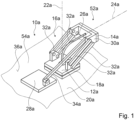
- FIG 1 shows a handling device 10a for handling products.
- the handling device 10a comprises at least one handling unit 52a (see also Figures 2 and 3 ).
- the handling unit 52a is intended to transport and handle products, for example to rotate, grip, lift, lower, or the like and/or to process.
- the handling unit 52a comprises at least one handling element 12a.
- the handling unit 52a comprises at least one holding element 14a.
- the holding element 14a is movably mounted relative to the handling element 12a.
- the holding element 14a is rotatable relative to the handling element 12a.
- the holding element 14a is translationally movable relative to the handling element 12a.
- the handling unit 52a comprises at least one platform element 30a.
- the platform element 30a is movable, in particular translationally, relative to the handling element 12a.
- the platform element 30a is mounted, in particular translationally, on the handling element 12a via four connecting elements 32a of the handling unit 52a.
- the handling unit 52a it is conceivable for the handling unit 52a to have a number of connecting elements 32a that differs from four, for example, only one connecting element 32a, two connecting elements 32a, three connecting elements 32a, or more than four connecting elements 32a, via which the platform element 30a is connected to the handling element 12a.
- the connecting elements 32a are designed as struts.
- connecting elements 32a are movably connected to the handling element 12a and/or the platform element 30a.
- the holding element 14a is mounted on the platform element 30a, preferably rotatably mounted.
- the holding element 14a is designed as a storage for products for handling, in particular transporting, the products.
- the holding element 14a is designed as a gripper for gripping products, or as an adapter for connection to a gripper or the like, or as another holding element 14a that appears appropriate to a person skilled in the art.
- the platform element 30a and/or the holding element 14a are/is arranged at a distance from the handling element 12a.
- the handling element 12a is plate-shaped. However, it is also conceivable that the handling element 12a has another shape that appears appropriate to a person skilled in the art.
- the holding element 14a and/or the platform element 30a are/is in at least one Operating state of the handling unit 52a arranged at a distance from a main extension plane of the handling element 12a.
- the handling unit 52a comprises at least one orientation unit 16a, by means of which an angular orientation between the handling element 12a and the holding element 14a can be adjusted.
- a rotational movement of the holding element 14a relative to the handling element 12a can be generated.
- a rotational movement of the holding element 14a relative to the platform element 30a can be generated.
- a movement of the holding element 14a relative to the platform element 30a and/or the handling element 12a that can be generated by the orientation unit 16a is different from a translational movement of the holding element 14a.
- a rotational movement of the holding element 14a relative to the handling element 12a can be generated in order to adjust an angular orientation between the holding element 14a and the handling element 12a.
- the orientation unit 16a has at least one adjustment element 18a.
- an angular orientation between the handling element 12a and the holding element 14a can be adjusted.
- An angular orientation between the handling element 12a and the holding element 14a can be generated by a rotational movement of the adjustment element 18a relative to the handling element 12a.
- the adjustment element 18a is connected to the holding element 14a in such a way that an angular orientation between the handling element 12a and the holding element 14a can be generated by a translational movement of the adjustment element 18a relative to the handling element 12a.
- the adjustment element 18a is arranged at a distance from the platform element 30a and/or the holding element 14a.
- the adjustment element 18a is movable relative to the platform element 30a.
- the adjustment element 18a is mechanically connected to the platform element 30a and the holding element 14a at least via the handling element 12a and the connecting elements 32a. By moving the adjustment element 18a relative to the handling element 12a, an angular orientation between the handling element 12a and the holding element 14a can be continuously adjusted.
- the handling unit 52a is intended for use with a planar drive.
- the handling device 10a comprises at least one drive unit 20a for driving the adjustment element 18a.
- the drive unit 20a is designed as a planar drive.
- the handling device 10a comprises at least one control unit (not shown here) for controlling the drive unit 20a.
- the adjustment element 18a is designed as a mover. Movers can be driven, in particular, by the drive unit 20a to move relative to a drive surface 36a of the drive unit 20a.
- the adjustment element 18a is mounted in an electromagnetic field in an at least substantially frictionless manner.
- the drive unit 20a is provided to generate the electromagnetic field.
- the drive unit 20a generates electromagnetic forces for driving the handling unit 52a, in particular the adjustment element 18a, and/or for electromagnetic linear mounting or levitation of the handling unit 52a, in particular the adjustment element 18a, via the preferably electrically excited drive surface 36a of the drive unit 20a.
- the drive unit 20a it is also conceivable for the drive unit 20a to be designed as a fluid-based planar drive.
- the drive unit 20a has at least one plate element 54a.
- the drive unit 20a preferably comprises a plurality of plate elements 54a, wherein the plate elements 54a are preferably identical or alternatively different from one another (only one plate element 54a is shown schematically here).
- the plate elements 54a of the plurality of plate elements 54a preferably abut one another.
- plate elements 54a of the plurality of plate elements 54a form the drive surface 36a of the drive unit 20a.
- the plate elements 54a each have a rectangular or a square shape (not shown here). Alternatively, it is also conceivable for the plate elements 54a to have a different shape that would be deemed appropriate by a person skilled in the art.
- the plate elements 54a each comprise a coil unit (not shown here), a sensor unit (not shown here) and an electronics unit (not shown here), in particular a power electronics unit.
- Plate elements 54a each have a layered structure.
- the plate elements 54a each have a coil level (not shown here), a sensor level (not shown here), and/or a power electronics level (not shown here).
- the respective coil level of the plate elements 54a is formed by the respective coil unit.
- the respective sensor level of the plate elements 54a is formed by the respective sensor unit.
- the respective power electronics level of the plate elements 54a is formed by the respective electronics unit, in particular the power electronics unit.
- the plate elements 54a each to have a structure other than a layered structure that would appear appropriate to a person skilled in the art.
- the handling device 10a comprises a connection unit (not shown here), in particular a bus system, which connects the plate elements 54a, in particular the electronic units, the coil units and/or the sensor units of the plate elements 54a, to the control unit, at least in terms of control technology.
- the handling device 10a has, in particular, a power supply unit (not shown here), via which the plate elements 54a, preferably the electronic units, the coil units and/or the sensor units, can be supplied with electrical energy.
- the power supply unit has, for example, at least one cable or the like for transmitting electrical energy to the plate elements 54a.
- the control unit comprises at least one processor and one memory element, as well as an operating program stored on the memory element.
- the memory element is designed as a digital storage medium, for example, as a hard disk or the like.
- the adjusting element 18a is movable relative to the drive surface 36a, in particular by a drive via the drive unit 20a.
- a driving force acting on the adjusting element 18a can be generated, in particular in order to generate a movement, preferably a translational movement and/or a rotational movement, of the adjusting element 18a on the drive surface.
- the adjusting element 18a is displaceable and/or rotatable in two degrees of freedom relative to the drive surface 36a.
- the adjusting element 18a is movable parallel to the drive surface 36a, at least in the operating state, in particular in a direction running parallel to the drive surface 36a. Movement plane.
- the drive unit 20a is provided to drive the adjustment element 18a to perform movements that run at least substantially parallel to the drive surface 36a.
- the adjustment element 18a generates a force on the drive surface 36a.
- the adjustment element 18a comprises at least one magnetic field generating element (not shown here) for generating a magnetic field.
- the magnetic field generating element is designed, for example, as a magnet, in particular a permanent magnet, or the like.
- the magnetic field generating element is provided to interact with at least one of the coil units of the drive unit 20a to drive the adjustment element 18a. For example, interaction of the at least one magnetic field generating element of the adjustment element 18a with the drive unit 20a creates an air gap between the drive surface 36a and the adjustment element 18a.
- the drive unit 20a is provided to generate the rotation of the adjustment element 18a about the rotation axis 22a, in particular relative to the handling element 12a, in order to adjust an angular orientation between the handling element 12a and the holding element 14a.
- the rotation axis 22a extends at least substantially perpendicular to the plane of movement in which the adjustment element 18a is movable.
- the rotation axis 22a extends at least substantially perpendicular to the drive surface 36a.
- the holding element 14a has a rotation axis 24a, about which the holding element 14a is rotatable to adjust an angular orientation between the handling element 12a and the holding element 14a, wherein the rotation axis 24a extends at an angle to the rotation axis 22a of the adjusting element 18a.
- the rotation axis 22a extends to the rotation axis 24a at an angle that is greater than 0° and less than 180°, preferably greater than 45° and less than 135°.
- the rotation axis 22a intersects the rotation axis 24a. Alternatively, it is also conceivable that the rotation axis 22a is free of an intersection point with the rotation axis 24a.
- the rotation axis 22a extends at least substantially parallel to the rotation axis 24a, in particular at a distance from the rotation axis 22a.
- the rotation axis 22a corresponds to the rotation axis 24a.
- An angle between the rotation axis 24a and the rotation axis 22a is at least substantially 90°. Particularly preferably, the angle between the rotation axis 24a and the rotation axis 22a is exactly 90°.
- the rotation axis 24a runs at least substantially parallel to the drive surface 36a, in particular the plane of movement, and/or the main extension plane of the handling element 12a.
- the rotation axis 24a is free of an intersection point with the drive surface 36a and/or the handling element 12a.
- the rotation axis 24a to intersect the handling element 12a and/or the drive surface 36a.
- the holding element 14a is infinitely rotatable about the rotation axis 24a. Alternatively, however, it is also conceivable that a maximum angle of rotation of the holding element 14a around the axis of rotation 24a is limited, for example to a maximum of 360°, 180°, 90° or the like.
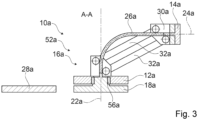
- the orientation unit 16a has at least one torque transmission element 26a, which is connected in a rotationally fixed manner to the adjustment element 18a.
- the torque transmission element 26a is arranged on the adjustment element 18a on a side facing away from the drive surface 36a. It is conceivable that the torque transmission element 26a is detachably connected, preferably non-destructively detachably, to the adjustment element 18a or is integrally connected to the adjustment element 18a.
- the torque transmission element 26a is designed as a flexible, in particular elastically bendable, shaft. Alternatively, it is also conceivable that the torque transmission element 26a is designed as a cardan shaft, as a rigid shaft, or as another torque transmission element 26a that would be deemed appropriate by a person skilled in the art.
- the torque transmission element 26a is connected in a rotationally fixed manner to the holding element 14a. It is conceivable that the torque transmission element 26a is detachably connected, preferably non-destructively detachably, to the holding element 14a or is integrally connected to the holding element 14a. It is also conceivable that the holding element 14a is formed integrally with the adjusting element 18a and/or the torque transmission element 26a.
- the handling element 12a is designed as a bearing plate.
- the handling element 12a is mounted on the adjustment element 18a.
- the handling element 12a is mounted on the adjustment element 18a.
- the handling element 12a is mounted on the adjustment element 18a via at least one bearing element 56a of the handling unit 52a (see Figure 3 ).
- the bearing element 56a is designed, for example, as a rolling bearing, in particular a ball bearing, or the like.
- the handling element 12a to be slidably mounted on the adjustment element 18a.
- the handling element 12a is rotatably mounted on the adjustment element 18a.
- the handling element 12a is movable only in terms of rotational movements relative to the adjustment element 18a.
- the handling unit 52a comprises at least one further handling element 28a, which holds the handling element 12a during rotation of the adjustment element 18a.
- the further handling element 28a is translationally movable relative to the handling element 12a and the adjustment element 18a.
- the further handling element 28a is rotatable relative to the adjustment element 18a.
- the further handling element 12a is arranged in a rotationally fixed manner with respect to the handling element 12a, in particular at least with respect to rotations about axes that run at least substantially parallel to the rotation axis 22a.
- the handling unit 52a has at least one further connecting element 34a, which connects the further handling element 28a, preferably mechanically, to the handling element 12a.
- the further connecting element 34a is designed as a strut.
- the further connecting element 34a is designed as another connecting element that would be deemed appropriate by a person skilled in the art.
- the further connecting element 34a is arranged on the further handling element 28a so as to be movable, preferably rotatable.
- the further connecting element 34a is movable, preferably rotatable, relative to the handling element 12a.
- the further handling element 28a is connected to the platform element 30a via the further connecting element 34a.
- the further Handling element 28a is drivable by drive unit 20a.
- a movement, in particular a translational movement, of the further handling element 28a relative to handling element 12a a distance between handling element 12a and platform element 30a and/or holding element 14a can be adjusted, in particular at least viewed in a direction parallel to rotation axis 22a.
- FIG 4 shows a schematic sequence of a method for handling products by means of the handling device 10a.
- the angular orientation between the handling element 12a and the holding element 14a is adjusted, in particular in at least one method step 48a, preferably by means of the orientation unit 16a.
- the adjusting element 18a is driven by the drive unit 20a to rotate about the rotation axis 22a. Due to the rotation of the adjusting element 18a, a torque is transmitted via the torque transmission element 26a to the holding element 14a. It is conceivable that the torque is transmitted without transmission. Alternatively, it is also conceivable that the torque is translated during transmission to the holding element 14a.
- the adjustment element 18a is driven, preferably in a further method step 50a, to perform a translational movement, preferably relative to the drive surface 36a, preferably in the plane of movement, by the drive unit 20a.
- the handling element 12a is moved translationally by the translational movement of the adjustment element 18a.
- the further handling element 28a is driven by the drive unit 20a to perform a translational movement relative to the handling element 12a.
- a translational movement of the further handling element 28a relative to the handling element 12a generates, in particular, a translational movement of the platform element 30a and/or the holding element 14a relative to the handling element 12a.
- FIG. 5 shows a handling device 10b for handling products.
- the handling device 10b comprises at least one handling unit 52b.
- the handling unit 52b comprises at least one handling element 12b.
- the handling unit 52b comprises at least one holding element 14b.
- the holding element 14b is movably mounted relative to the handling element 12b.
- the handling unit 52b comprises at least one orientation unit 16b, by means of which an angular orientation between the handling element 12b and the holding element 14b can be adjusted.
- the holding element 14b is merely rotatably mounted relative to the handling element 12b.
- the handling unit 52b comprises at least one platform element 30b.
- the platform element 30b is rigidly connected to the handling element 12b.
- the platform element 30b is rigidly connected to the handling element 12b via two connecting elements 32b of the handling unit 52b.
- the handling unit 52b it is also conceivable for the handling unit 52b to have a different number of connecting elements 32b, for example, only one connecting element 32b or more than two connecting elements 32b, via which the platform element 30b is rigidly connected to the handling element 12b.
- the handling element 12b to be formed integrally with the platform element 30b.
- the handling element 12b is arranged separately from an adjustment element 18b of the handling unit 52b in at least one operating state.
- the handling element 12b which is arranged separately from the adjustment element 18b, is not mounted on the adjustment element 18b.
- the handling element 12b is arranged at a distance from the adjustment element 18b, preferably at least when viewed in a plane running parallel to a drive surface (not shown here) of a drive unit (not shown here) of the handling device 10b and/or a plane of movement of the adjustment element 18b.
- the adjustment element 18b which is arranged separately from the handling element 12b, is designed as a mover, which can preferably be driven by the drive unit 20b.
- the handling unit 52b has a torque transmission element 26b, which is connected in a rotationally fixed manner to the adjustment element 18b and the holding element 14b.
- a torque transmission element 26b By rotating the adjustment element 18b about a rotation axis 22b relative to the handling element 12b, an angular orientation between the holding element 14b and the handling element 12b can be adjusted.
- An axis of rotation 24b of the holding element 14b runs at least substantially perpendicular to the axis of rotation 22b.
- FIG. 6 shows a handling device 10c for handling products.
- the handling device 10c comprises at least one handling unit 52c.
- the handling unit 52c comprises at least one handling element 12c.
- the handling unit 52c comprises at least one holding element 14c.
- the holding element 14c is movably mounted relative to the handling element 12c.
- the handling unit 52c comprises at least one orientation unit 16c, by means of which an angular orientation between the handling element 12c and the holding element 14c can be adjusted.
- the holding element 14c is translationally movable and rotatable relative to the handling element 12c.
- the handling unit 52c comprises at least one platform element 30c.
- the platform element 30c is movably connected to the handling element 12b via four connecting elements 32c of the handling unit 52c.
- the handling unit 52c it is conceivable for the handling unit 52c to have a number of connecting elements 32c different from four, for example, only one connecting element 32c, two connecting elements 32c, three connecting elements 32c, or more than four connecting elements 32c, via which the platform element 30c is connected to the handling element 12c.
- the holding element 14c is rotatably mounted on the platform element 30c.
- an angular orientation between the holding element 14c and the handling element 12c can be adjusted via a torque transmission element 26c of the handling unit 52c.
- the adjustment element 18c is designed as a mover and can be driven by a drive unit (not shown here) of the handling device 10c to move, in particular relative to a drive surface (not shown here) of the drive unit.
- the handling element 12c is mounted on the adjustment element 18c.
- the handling unit 52c comprises at least one further handling element 28c, which is designed as a bearing plate.
- the further handling element 28c is arranged on a further adjustment element 42c of the handling unit 52c.
- the further handling element 28c is rotatably mounted on the further adjustment element 42c.
- the further adjustment element 42c is designed as a mover, which can be driven in particular by the drive unit.
- the handling unit 52c has at least one further connecting element 34c, which connects the further handling element 28c, preferably mechanically, to the handling element 12c.
- the further connecting element 34c is designed as a strut. Alternatively, it is also conceivable for the further connecting element 34c to be designed as another connecting element that would appear appropriate to a person skilled in the art.
- the further connecting element 34c is arranged movably, preferably rotatably, on the further handling element 28c.
- the further handling element 28c is connected to the platform element 30c via the further connecting element 34c.
- a translational movement of the further handling element 28a relative to the handling element 12c can generate a translational movement of the platform element 30c relative to the handling element 12c.
- a distance between the handling element 12c and the platform element 30c adjustable, in particular at least viewed in a direction parallel to the rotation axis 22c.
- the handling unit 52c comprises at least one further holding element 38c.
- the further adjustment element 42c is provided for adjusting an angular orientation between the further holding element 38c and the handling element 12c and/or the further handling element 28c.
- the further holding element 38c is rotatably mounted on the platform element 30c, in particular at a distance from the holding element 14c.
- the handling unit 52c has at least one further torque transmission element 40c.
- the further torque transmission element 40c is connected in a rotationally fixed manner to the further holding element 38c and the further adjustment element 42c. It is conceivable that the further torque transmission element 40c is detachably connected, preferably non-destructively detachably, or integrally connected to the further holding element 38c and/or the further adjustment element 42c.
- an angular orientation between the further holding element 38c and the further handling element 28c and/or the handling element 12c can be adjusted.
- a rotation of the further adjustment element 42c a rotation of the further holding element 38c about an axis of rotation 46c can be generated, in particular in order to adjust an angular orientation between the further holding element 38c and the further handling element 28c.
- An axis of rotation 44c of the rotation of the further adjustment element 42c runs at least substantially parallel to the axis of rotation 22c of the adjustment element 18c.
- the axis of rotation 46c runs at least substantially parallel to the axis of rotation 24c.
- the axis of rotation 46c runs at least substantially perpendicular to the axis of rotation 22c and/or the axis of rotation 44c.
Landscapes
- Engineering & Computer Science (AREA)
- Mechanical Engineering (AREA)
- Manipulator (AREA)
Description
- Die Erfindung betrifft eine Handhabungsvorrichtung nach dem Oberbegriff des Anspruchs 1 und ein Verfahren zu einem Transportieren von Produkten nach dem Oberbegriff des Anspruchs 9.
- Derartige Handhabungsvorrichtungen und Verfahren sind bereits aus
WO 2018/176137 A1 bekannt. Nachteilig an diesen Handhabungsvorrichtungen und Verfahren ist, dass das Halteelement relativ zu dem Handhabungselement derart gelagert ist, dass das Halteelement relativ zu dem Handhabungselement lediglich Translationsbewegungen ausführen kann. Insbesondere ist es nicht möglich ein Drehmoment auf das Halteelement zu übertragen, um das Halteelement relativ zu dem Handhabungselement zu verdrehen. Dadurch sind Bewegungsmöglichkeiten des Halteelements relativ zu dem Handhabungselement und somit nachteilig auch ein Funktionsbereich der bekannten Handhabungsvorrichtungen und Verfahren eingeschränkt. Diese Nachteile werden von der vorliegenden Erfindung überwunden. - Des Weiteren sind aus
DE 199 60 487 A1 ,EP 4 005 742 A1 ,WO 2017/036812 A1 undDE 10 2018 216 393 B4 ebenfalls bereits Handhabungsvorrichtungen und Verfahren zu einer Handhabung von Produkten bekannt. - Ferner ist aus
DE 20 2016 101 453 U1 bereits eine Handhabungsvorrichtung zu einer Handhabung von Produkten bekannt, wobei die Handhabungsvorrichtung zumindest eine Handhabungseinheit umfasst, die zumindest ein Handhabungselement und zumindest ein Halteelement, welches relativ zu dem Handhabungselement beweglich gelagert ist, und eine Orientierungseinheit umfasst, mittels welcher eine Winkelorientierung zwischen dem Handhabungselement und dem Halteelement einstellbar ist. Ein Verfahren zu einer Handhabung von Produkten mittels der aus derDE 20 2016 101 453 U1 bereits bekannten Handhabungsvorrichtung ist ebenfalls bereits aus derDE 20 2016 101 453 U1 bekannt. - Ferner sind aus
WO 2020/243814 A1 undDE 10 2020 120 294 A1 ebenfalls Handhabungsvorrichtungen sowie Verfahren zu einer Handhabung von Produkten bekannt, wobei dieWO 2020/243814 A1 die Merkmale des Oberbegriffs des Anspruchs 1 sowie des Oberbegriffs des Anspruchs 9 offenbart. - Die Aufgabe der Erfindung besteht insbesondere darin, eine gattungsgemäße Handhabungsvorrichtung und ein gattungsgemäßes Verfahren mit verbesserten Eigenschaften hinsichtlich einer flexiblen Handhabung von Produkten bereitzustellen. Die Aufgabe wird erfindungsgemäß durch die Merkmale des Anspruchs 1 bzw. des Anspruchs 9 gelöst, während vorteilhafte Ausgestaltungen und Weiterbildungen der Erfindung den Unteransprüchen entnommen werden können.
- Die Erfindung geht aus von einer Handhabungsvorrichtung zu einer Handhabung von Produkten, mit zumindest einer Handhabungseinheit, die zumindest ein Handhabungselement und zumindest ein Halteelement, welches relativ zu dem Handhabungselement beweglich gelagert ist, und eine Orientierungseinheit umfasst, mittels welcher eine Winkelorientierung zwischen dem Handhabungselement und dem Halteelement einstellbar ist, wobei die Orientierungseinheit zumindest ein Einstellelement aufweist, wobei durch eine Bewegung des Einstellelements relativ zu dem Handhabungselement die Winkelorientierung zwischen dem Handhabungselement und dem Halteelement einstellbar ist, und mit einer als Planarantrieb ausgebildeten Antriebseinheit zu einem Antrieb des Einstellelements.
- Es wird vorgeschlagen, dass die Orientierungseinheit zumindest ein Drehmomentübertragungselement aufweist, welches drehfest mit dem Einstellelement verbunden ist, wobei das Drehmomentübertragungselement als Kardanwelle oder als flexible, insbesondere elastisch biegbare, Welle ausgebildet ist. Die Handhabungseinheit ist vorzugsweise dazu vorgesehen, Produkte zu transportieren, zu handhaben, beispielsweise zu drehen, zu greifen, zu heben, zu senken oder dergleichen und/oder zu bearbeiten. Bevorzugt ist das Halteelement relativ zu dem Handhabungselement drehbar gelagert. Zusätzlich ist denkbar, dass das Halteelement relativ zu dem Handhabungselement translatorisch bewegbar ist. Es ist jedoch auch denkbar, dass das Halteelement relativ zu dem Handhabungselement lediglich drehbar gelagert ist. Bevorzugt ist das Halteelement über zumindest ein weiteres Bauteil der Handhabungseinheit mit dem Handhabungselement, vorzugsweise mechanisch, verbunden, wobei das Halteelement insbesondere an dem weiteren Bauteil gelagert ist. Es ist alternativ jedoch auch denkbar, dass das Halteelement an dem Handhabungselement, insbesondere unmittelbar, anliegend beweglich gelagert ist.
- Bevorzugt umfasst die Handhabungseinheit zumindest ein Plattformelement. Bevorzugt ist das Plattformelement, insbesondere translatorisch, relativ zu dem Handhabungselement bewegbar. Bevorzugt ist das Plattformelement in unterschiedlichen Abständen und Positionen relativ zu dem Handhabungselement anordenbar. Vorzugsweise ist das Plattformelement über zumindest ein Verbindungselement der Handhabungseinheit, an dem Handhabungselement, insbesondere translatorisch, gelagert. Das zumindest eine Verbindungselement ist beispielsweise als Strebe oder dergleichen ausgebildet. Besonders bevorzugt ist das zumindest eine Verbindungselement beweglich mit dem Handhabungselement und/oder dem Plattformelement verbunden. Alternativ ist jedoch auch denkbar, dass das Plattformelement starr mit dem Handhabungselement verbunden ist. Es ist insbesondere auch denkbar, dass das Handhabungselement einstückig mit dem Plattformelement ausgebildet ist. Unter "einstückig" kann zumindest stoffschlüssig verbunden verstanden werden, beispielsweise durch einen Schweißprozess, einen Klebeprozess, einen Anspritzprozess und/oder einen anderen, dem Fachmann als sinnvoll erscheinenden Prozess, und/oder vorteilhaft in einem Stück geformt verstanden werden, wie beispielsweise durch eine Herstellung aus einem Guss und/oder durch eine Herstellung in einem Ein- oder Mehrkomponentenspritzverfahren und vorteilhaft aus einem einzelnen Rohling.
- Das Halteelement ist insbesondere an dem Plattformelement gelagert, vorzugsweise drehbar gelagert. Beispielsweise ist das Halteelement als eine Ablage für Produkte zu einer Handhabung, insbesondere einem Transport, der Produkte ausgebildet. Es ist alternativ auch denkbar, dass das Halteelement als ein Greifer zu einem Greifen von Produkten, als ein Adapter zu einer, vorzugsweise lösbaren Verbindung, mit einem Greifer oder dergleichen, oder als ein anderes, einem Fachmann als sinnvoll erscheinendes Halteelement ausgebildet ist. Insbesondere in einem bevorzugten Ausführungsbeispiel ist das Plattformelement und/oder das Halteelement beabstandet zu dem Handhabungselement angeordnet. Bevorzugt ist das Handhabungselement plattenförmig ausgebildet. Es ist jedoch auch denkbar, dass das Handhabungselement eine andere, einem Fachmann als sinnvoll erscheinende Form aufweist. Das Halteelement und/oder das Plattformelement sind/ist in zumindest einem Betriebszustand der Handhabungseinheit beabstandet zu einer Haupterstreckungsebene des Handhabungselements angeordnet. Unter einer "Haupterstreckungsebene" einer Baueinheit oder eines Elements kann eine Ebene verstanden werden, welche parallel zu einer größten Seitenfläche eines kleinstmöglichen gedachten Quaders ist, welcher die Baueinheit gerade noch vollständig umschließt, und insbesondere durch den Mittelpunkt des Quaders verläuft.
- Mittels der Orientierungseinheit ist insbesondere eine Drehbewegung des Halteelements relativ zu dem Handhabungselement und/oder dem Plattformelement erzeugbar. Eine durch die Orientierungseinheit erzeugbare Bewegung des Halteelements relativ zu dem Plattformelement und/oder dem Handhabungselement ist vorzugsweise verschieden von einer Translationsbewegung des Halteelements relativ zu dem Handhabungselement. Vorzugsweise ist durch die Orientierungseinheit eine Drehbewegung des Halteelements relativ zu dem Handhabungselement erzeugbar, um eine Winkelorientierung zwischen dem Halteelement und dem Handhabungselement einzustellen.
- Durch die erfindungsgemäße Ausgestaltung der Handhabungsvorrichtung kann eine Handhabungseinheit zur Verfügung gestellt werden, die es ermöglicht, Drehmomente an das Halteelement zu übertragen, um eine Drehung des Halteelements relativ zu dem Handhabungselement zu erzeugen. Vorteilhaft können Produkte besonders flexibel gehandhabt werden. Vorteilhaft kann die Handhabungsvorrichtung besonders flexibel eingesetzt werden. Vorteilhaft kann eine Handhabungseinheit mit einem besonders großen Funktionsumfang zur Verfügung gestellt werden.
- Erfindungsgemäß umfasst die Orientierungseinheit zumindest das Einstellelement, wobei durch eine Bewegung des Einstellelements relativ zu dem Handhabungselement die Winkelorientierung zwischen dem Handhabungselement und dem Halteelement einstellbar ist. Es ist denkbar, dass eine Winkelorientierung zwischen dem Handhabungselement und dem Halteelement durch eine Translationsbewegung und/oder eine Drehbewegung des Einstellelements relativ zu dem Handhabungselement erzeugbar ist. Das Einstellelement ist insbesondere beabstandet zu dem Plattformelement und/oder dem Halteelement angeordnet. Vorzugsweise ist das Einstellelement relativ zu dem Plattformelement bewegbar. Insbesondere ist das Einstellelement über zumindest ein weiteres Bauteil der Handhabungseinheit mechanisch mit dem Plattformelement, dem Handhabungselement und/oder dem Halteelement verbunden. Bevorzugt sind sämtliche Bauteile der Handhabungseinheit mechanisch miteinander verbunden. Vorzugsweise ist durch eine Bewegung des Einstellelements relativ zu dem Handhabungselement eine Winkelorientierung zwischen dem Handhabungselement und dem Halteelement stufenlos einstellbar. Vorteilhaft kann eine Winkelorientierung zwischen dem Halteelement und dem Handhabungselement besonders einfach und präzise eingestellt werden.
- Erfindungsgemäß umfasst die Handhabungsvorrichtung die als Planarantrieb ausgebildete Antriebseinheit zu einem Antrieb des Einstellelements. Die Handhabungseinheit ist insbesondere zu einer Verwendung mit dem Planarantrieb vorgesehen. Die Handhabungsvorrichtung umfasst vorzugsweise zumindest eine Steuereinheit zu einer Ansteuerung der Antriebseinheit. Bevorzugt ist das Einstellelement als Mover ausgebildet. Insbesondere sind Mover durch die Antriebseinheit antreibbar. Das Handhabungselement ist bevorzugt als Lagerplatte ausgebildet. Es ist alternativ auch denkbar, dass das Handhabungselement als Mover ausgebildet ist. Es ist denkbar, dass das als Mover ausgebildete Handhabungselement durch die Antriebseinheit antreibbar ist. Vorzugsweise ist zumindest das Einstellelement in zumindest einem Betriebszustand in einem elektromagnetischen Feld zumindest im Wesentlichen reibungsfrei gelagert. Die Antriebseinheit ist insbesondere in dem Betriebszustand dazu vorgesehen, das elektromagnetische Feld zu erzeugen. Unter "vorgesehen" soll speziell eingerichtet, speziell ausgelegt und/oder speziell ausgestattet verstanden werden. Darunter, dass ein Objekt zu einer bestimmten Funktion vorgesehen ist, soll verstanden werden, dass das Objekt diese bestimmte Funktion in zumindest einem Anwendungs- und/oder Betriebszustand erfüllt und/oder ausführt. Die Antriebseinheit erzeugt bevorzugt zumindest in dem Betriebszustand elektromagnetische Kräfte für einen Antrieb der Handhabungseinheit, insbesondere des Einstellelements, und/oder für eine elektromagnetische Linearlagerung oder Levitation der Handhabungseinheit, insbesondere des Einstellelements, über eine, vorzugsweise elektrisch erregte, Antriebsfläche der Antriebseinheit. Das Einstellelement ist relativ zu der Antriebsfläche bewegbar, vorzugsweise durch einen Antrieb durch die Antriebseinheit. Mittels der Antriebseinheit ist vorzugsweise eine auf das Einstellelement wirkende Antriebskraft erzeugbar, insbesondere um eine Bewegung, bevorzugt eine Translationsbewegung und/oder eine Rotationsbewegung, des Einstellelements relativ zu der Antriebsfläche zu erzeugen. Das Einstellelement ist insbesondere in zwei Freiheitsgraden relativ zu der Antriebsfläche verschiebbar und/oder drehbar. Vorzugsweise ist das Einstellelement zumindest in dem Betriebszustand parallel zu der Antriebsfläche bewegbar, bevorzugt in einer zu der Antriebfläche parallel verlaufenden Bewegungsebene. Bevorzugt ist die Antriebseinheit dazu vorgesehen, das Einstellelement zu Bewegungen anzutreiben, die zumindest im Wesentlichen parallel zu der Antriebsfläche verlaufen. Unter "im Wesentlichen parallel" kann hier eine Ausrichtung einer Richtung relativ zu einer Bezugsrichtung, insbesondere in einer Ebene, verstanden werden, wobei die Richtung gegenüber der Bezugsrichtung eine Abweichung insbesondere kleiner als 8°, vorteilhaft kleiner als 5° und besonders vorteilhaft kleiner als 2° aufweist. Das Einstellelement erzeugt vorzugsweise eine Kraft auf die Antriebsfläche. Das Einstellelement umfasst bevorzugt zumindest ein Magnetfelderzeugungselement zu einer Erzeugung eines Magnetfelds. Das Magnetfelderzeugungselement ist beispielsweise als ein Magnet, insbesondere ein Permanentmagnet, oder dergleichen ausgebildet. Das Magnetfelderzeugungselement ist insbesondere dazu vorgesehen, zu einem Antrieb des Einstellelements, mit der Antriebseinheit zusammenzuwirken. Beispielsweise erzeugt ein Zusammenwirken des zumindest einen Magnetfelderzeugungselements des Einstellelements mit der Antriebseinheit einen Luftspalt zwischen der Antriebsfläche und dem Einstellelement.
- Vorzugsweise gilt die Beschreibung des Einstellelements bezüglich eines Antriebs durch die Antriebseinheit analog für weitere als Mover ausgebildete Bauteile der Handhabungsvorrichtung, insbesondere für das in zumindest einem Ausführungsbeispiel als Mover ausgebildete Handhabungselement. Alternativ ist auch denkbar, dass die Antriebseinheit als ein fluidbasierter Planarantrieb ausgebildet ist. Vorteilhaft kann eine Winkelorientierung zwischen dem Halteelement und dem Handhabungselement besonders komfortabel eingestellt werden. Vorteilhaft kann eine Winkelorientierung zwischen dem Halteelement und dem Handhabungselement zumindest teilweise automatisch durch eine Ansteuerung der Antriebseinheit eingestellt werden.
- Ferner wird vorgeschlagen, dass durch eine Rotation des Einstellelements um eine Rotationsachse eine Winkelorientierung zwischen dem Handhabungselement und dem Halteelement einstellbar ist. Insbesondere ist die Antriebseinheit dazu vorgesehen, die Rotation des Einstellelements um die Rotationsachse zu erzeugen, um eine Winkelorientierung zwischen dem Handhabungselement und dem Halteelement einzustellen. Insbesondere ist durch eine Rotation des Einstellelements relativ zu dem Handhabungselement eine Winkelorientierung zwischen dem Halteelement und dem Handhabungselement einstellbar. Vorteilhaft kann eine besonders platzsparende Einstellung der Winkelorientierung zwischen dem Halteelement und dem Handhabungselement durch eine Bewegung des Einstellelements realisiert werden. Vorteilhaft kann eine besonders flexible Handhabung von Produkten mittels der Handhabungsvorrichtung erreicht werden.
- Des Weiteren wird vorgeschlagen, dass die Rotationsachse zumindest im Wesentlichen senkrecht zu einer, insbesondere der zuvor bereits genannten, Bewegungsebene verläuft, in welcher das Einstellelement bewegbar ist. Unter "im Wesentlichen senkrecht" kann eine Ausrichtung einer Richtung relativ zu einer Bezugsrichtung verstanden werden, wobei die Richtung und die Bezugsrichtung, insbesondere in einer Projektionsebene betrachtet, einen Winkel von 90° einschließen und der Winkel eine maximale Abweichung von insbesondere kleiner als 8°, vorteilhaft kleiner als 5° und besonders vorteilhaft kleiner als 2° aufweist. Insbesondere verläuft die Rotationsachse zumindest im Wesentlichen senkrecht zu der Antriebsfläche. Besonders bevorzugt verläuft die Rotationsachse genau senkrecht zu der Bewegungsebene und/oder der Antriebsfläche. Vorteilhaft kann eine Rotation des Einstellelements besonders einfach durch einen Planarantrieb erzeugt werden. Vorteilhaft kann eine besonders platzsparende Rotation des Einstellelements zu einer Einstellung einer Winkelorientierung zwischen dem Halteelement und dem Handhabungselement realisiert werden.
- Außerdem wird vorgeschlagen, dass das Halteelement eine Drehachse aufweist, um welche das Halteelement zu einer Einstellung einer Winkelorientierung zwischen dem Handhabungselement und dem Halteelement drehbar ist, wobei die Drehachse winklig zu der Rotationsachse des Einstellelements verläuft. Insbesondere verläuft die Rotationsachse zu der Drehachse in einem Winkel, der größer ist als 0° und kleiner ist als 180°, bevorzugt größer ist als 45° und kleiner ist als 135°. Bevorzugt schneidet die Rotationsachse die Drehachse. Alternativ ist auch denkbar, dass die Rotationsachse frei von einem Schnittpunkt mit der Drehachse ist. Ferner ist alternativ denkbar, dass die Rotationsachse zumindest im Wesentlichen parallel zu der Drehachse verläuft, insbesondere beabstandet zu der Rotationsachse. Ferner ist alternativ auch denkbar, dass die Rotationsachse der Drehachse entspricht. Vorzugsweise ist eine Winkelstellung zwischen der Rotationsachse und der Drehachse fest. Alternativ ist auch denkbar, dass eine Winkelstellung der Rotationsachse zu der Drehachse einstellbar ist. Vorteilhaft kann die Handhabungseinheit besonders flexibel zu einer Handhabung von Produkten eingesetzt werden.
- Weiterhin wird vorgeschlagen, dass ein, insbesondere der zuvor bereits genannte, Winkel zwischen der Drehachse und der Rotationsachse zumindest im Wesentlichen 90° beträgt. Darunter, dass ein Winkel zumindest im Wesentlichen einen Wert beträgt soll insbesondere verstanden werden, dass der Winkel von dem Wert weniger als 25 %, vorzugsweise weniger als 10 % und besonders bevorzugt weniger als 5 % des Werts abweicht. In einem bevorzugten Ausführungsbeispiel beträgt der Winkel zwischen der Drehachse und der Rotationsachse genau 90°. Vorzugsweise verläuft die Drehachse zumindest im Wesentlichen parallel zu der Antriebsfläche, insbesondere der Bewegungsebene, und/oder der Haupterstreckungsebene des Handhabungselements. Die Drehachse ist insbesondere frei von einem Schnittpunkt mit der Antriebsfläche und/oder dem Handhabungselement. Es ist jedoch alternativ auch denkbar, dass die Drehachse das Handhabungselement und/oder die Antriebsfläche schneidet. Vorzugsweise ist das Halteelement um die Drehachse unendlich rotierbar. Alternativ ist jedoch auch denkbar, dass ein maximaler Drehwinkelbereich des Halteelements um die Drehachse begrenzt ist, beispielsweise auf maximal 360°, 180°, 90° oder dergleichen. Vorteilhaft kann die Handhabungseinheit besonders flexibel zu einer Handhabung von Produkten eingesetzt werden.
- Das Drehmomentübertragungselement ist vorzugsweise auf einer der Antriebsfläche abgewandten Seite an dem Einstellelement angeordnet. Es ist denkbar, dass das Drehmomentübertragungselement lösbar, vorzugsweise zerstörungsfrei lösbar, mit dem Einstellelement verbunden ist oder stoffschlüssig mit dem Einstellelement verbunden ist. Bevorzugt ist das Drehmomentübertragungselement drehfest mit dem Halteelement verbunden. Es ist denkbar, dass das Drehmomentübertragungselement lösbar, vorzugsweise zerstörungsfrei lösbar, mit dem Halteelement verbunden ist oder stoffschlüssig mit dem Halteelement verbunden ist. Es ist auch denkbar, dass das Halteelement einstückig mit dem Einstellelement und/oder dem Drehmomentübertragungselement ausgebildet ist. Vorteilhaft wird ein Drehmoment durch eine Bewegung, insbesondere eine Rotation, des Einstellelements besonders effizient übertragen, um eine Winkelorientierung zwischen dem Halteelement und dem Handhabungselement einzustellen.
- Des Weiteren wird vorgeschlagen, dass das Handhabungselement, insbesondere in zumindest einem Ausführungsbeispiel, an dem Einstellelement gelagert ist. Vorzugsweise ist das Handhabungselement auf dem Einstellelement gelagert. Insbesondere ist das Handhabungselement über zumindest ein Lagerelement der Handhabungseinheit an dem Einstellelement gelagert. Das Lagerelement ist beispielsweise als ein Wälzlager, insbesondere ein Kugellager, oder dergleichen ausgebildet. Es ist auch denkbar, dass das Handhabungselement an dem Einstellelement gleitend gelagert ist. Vorzugsweise ist das Handhabungselement drehbar an dem Einstellelement gelagert. Insbesondere ist das Handhabungselement lediglich hinsichtlich Drehbewegungen relativ zu dem Einstellelement bewegbar. Vorteilhaft können Produkte besonders flexibel gehandhabt werden bei gleichzeitig besonders geringem Platzbedarf, insbesondere um eine Winkelorientierung zwischen dem Halteelement und dem Handhabungselement einzustellen.
- Außerdem wird vorgeschlagen, dass die Handhabungseinheit zumindest ein weiteres Handhabungselement aufweist, welches das Handhabungselement bei einer Rotation des Einstellelements festhält. Vorzugsweise ist das weitere Handhabungselement relativ zu dem Handhabungselement und/oder dem Einstellelement bewegbar, vorzugsweise zumindest translatorisch. Das weitere Handhabungselement ist insbesondere beabstandet zu dem Handhabungselement und dem Einstellelement angeordnet. Vorzugsweise ist das weitere Handhabungselement, insbesondere in zumindest einem Ausführungsbeispiel, relativ zu dem Handhabungselement drehfest angeordnet. Die Handhabungseinheit weist vorzugsweise zumindest ein weiteres Verbindungselement auf, welches das weitere Handhabungselement, vorzugsweise mechanisch, mit dem Handhabungselement verbindet. Bevorzugt ist das weitere Verbindungselement als Strebe oder dergleichen ausgebildet. Vorzugsweise ist das weitere Handhabungselement zumindest über das zumindest eine weitere Verbindungselement relativ zu dem Handhabungselement drehfest angeordnet, insbesondere zumindest hinsichtlich Rotationen um Achsen, die zumindest im Wesentlichen parallel zu der Rotationsachse verlaufen. Bevorzugt ist das weitere Verbindungselement an dem weiteren Handhabungselement beweglich, vorzugsweise drehbar, angeordnet. Insbesondere ist das weitere Verbindungselement beweglich, vorzugsweise drehbar, relativ zu dem Handhabungselement. Besonders bevorzugt ist das weitere Handhabungselement über das weitere Verbindungselement mit dem Plattformelement verbunden. Insbesondere ist durch eine Translationsbewegung des weiteren Handhabungselements relativ zu dem Einstellelement und/oder dem Handhabungselement eine Translationsbewegung des Plattformelements und/oder des Halteelements relativ zu dem Handhabungselement erzeugbar. Vorzugsweise ist durch eine Bewegung, insbesondere eine Translationsbewegung, des weiteren Handhabungselements relativ zu dem Handhabungselement und/oder dem Einstellelement ein Abstand zwischen dem Handhabungselement und dem Plattformelement und/oder dem Halteelement einstellbar, insbesondere zumindest betrachtet in einer zu der Rotationsachse parallel verlaufenden Richtung. Das weitere Handhabungselement ist vorzugsweise als Mover ausgebildet. Das weitere Handhabungselement ist insbesondere durch die Antriebseinheit antreibbar. Alternativ ist auch denkbar, dass das weitere Handhabungselement als Lagerplatte oder dergleichen ausgebildet ist, die vorzugsweise auf einem weiteren Einstellelement der Handhabungseinheit angeordnet, vorzugsweise gelagert ist, wobei das weitere Einstellelement bevorzugt als Mover ausgebildet ist, der insbesondere durch die Antriebseinheit antreibbar ist. Es ist denkbar, dass die Handhabungseinheit zumindest ein weiteres Halteelement aufweist. Das weitere Einstellelement ist vorzugsweise zu einer Einstellung einer Winkelorientierung zwischen dem weiteren Halteelement und dem Handhabungselement und/oder dem weiteren Handhabungselement vorgesehen. Beispielsweise ist das weitere Halteelement an dem Plattformelement beweglich gelagert, insbesondere beabstandet zu dem Halteelement. Bevorzugt weist die Handhabungseinheit zumindest ein weiteres Drehmomentübertragungselement auf. Das weitere Drehmomentübertragungselement ist vorzugsweise drehfest mit dem weiteren Halteelement und dem weiteren Einstellelement verbunden. Es ist denkbar, dass das weitere Drehmomentübertragungselement lösbar, vorzugsweise zerstörungsfrei lösbar, oder einstückig mit dem weiteren Halteelement und/oder dem weiteren Einstellelement verbunden ist. Vorzugsweise ist durch eine Bewegung, insbesondere eine Rotation, des weiteren Einstellelements relativ zu dem weiteren Handhabungselement eine Winkelorientierung zwischen dem weiteren Halteelement und dem weiteren Handhabungselement und/oder dem Handhabungselement einstellbar. Eine Rotationsachse der Rotation des weiteren Einstellelements verläuft bevorzugt zumindest im Wesentlichen parallel zu der Rotationsachse des Einstellelements. Vorteilhaft kann vermieden werden, dass das Handhabungselement bei einer Rotation des Einstellelements mitrotiert. Vorteilhaft kann ein Drehmoment zu einer Einstellung einer Winkelorientierung zwischen dem Halteelement und dem Handhabungselement besonders effizient und zuverlässig übertragen werden.
- Weiterhin wird vorgeschlagen, dass das Handhabungselement in zumindest einem Betriebszustand, vorzugsweise in zumindest einem alternativen Ausführungsbeispiel, separat zu dem Einstellelement angeordnet ist. Insbesondere ist das separat zu dem Einstellelement angeordnete Handhabungselement nicht auf dem Einstellelement gelagert. Insbesondere ist das Handhabungselement beabstandet zu dem Einstellelement angeordnet, vorzugsweise zumindest betrachtet in einer zu der Antriebsfläche und/oder der Bewegungsebene parallel verlaufenden Ebene. Bevorzugt ist das separat zu dem Handhabungselement angeordnete Einstellelement als Mover ausgebildet, der vorzugsweise durch die Antriebseinheit antreibbar ist. Vorteilhaft kann konstruktiv besonders einfach ein Drehmoment auf das Halteelement zu einer Einstellung einer Winkelorientierung zwischen dem Halteelement und dem Handhabungselement übertragen werden. Ferner geht die Erfindung von einem Verfahren zu einer Handhabung von Produkten mittels einer Handhabungsvorrichtung, insbesondere einer erfindungsgemäßen Handhabungsvorrichtung, welche zumindest eine, insbesondere die zuvor bereits genannte, Handhabungseinheit mit zumindest einem, insbesondere das zuvor bereits genannte, Handhabungselement und zumindest einem, insbesondere dem zuvor bereits genannten, Halteelement aufweist, welches relativ zu dem Handhabungselement beweglich gelagert ist, wobei eine Winkelorientierung zwischen dem Handhabungselement und dem Halteelement eingestellt wird, wobei die Winkelorientierung zwischen dem Handhabungselement und dem Halteelement durch eine Bewegung eines, insbesondere des bereits zuvor genannten, Einstellelements der Orientierungseinheit relativ zu dem Handhabungselement eingestellt wird, wobei das Einstellelement mittels einer als Planarantrieb ausgebildeten Antriebseinheit der Handhabungsvorrichtung angetrieben wird. Es wird vorgeschlagen, dass die Orientierungseinheit zumindest ein Drehmomentübertragungselement aufweist, welches drehfest mit dem Einstellelement verbunden ist, wobei durch eine Rotation des Einstellelements ein Drehmoment über das als Kardanwelle oder als flexible, insbesondere elastisch biegbare, Welle ausgebildete Drehmomentübertragungselement an das Halteelement übertragen wird. Vorteilhaft ist es möglich Drehmomente an das Halteelement zu übertragen, um eine Drehung des Halteelements relativ zu dem Handhabungselement zu erzeugen. Vorteilhaft können Produkte besonders flexibel gehandhabt werden.
- Weitere Vorteile ergeben sich aus der folgenden Zeichnungsbeschreibung. In der Zeichnung sind drei Ausführungsbeispiele der Erfindung dargestellt. Die Zeichnung, die Beschreibung und die Ansprüche enthalten zahlreiche Merkmale in Kombination. Der Fachmann wird die Merkmale zweckmäßigerweise auch einzeln betrachten und zu sinnvollen weiteren Kombinationen zusammenfassen.
- Es zeigen:
- Fig. 1
- eine erfindungsgemäße Handhabungsvorrichtung zu einer Handhabung von Produkten in einer perspektivischen Darstellung,
- Fig. 2
- einen Teil der Handhabungsvorrichtung in einer Draufsicht,
- Fig. 3
- eine Querschnittsdarstellung der Handhabungsvorrichtung entlang der Linie A-A aus
Figur 2 , - Fig. 4
- einen schematischen Ablauf eines erfindungsgemäßen Verfahrens zu einer Handhabung von Produkten mittels der Handhabungsvorrichtung,
- Fig. 5
- eine erfindungsgemäße Handhabungsvorrichtung zu einer Handhabung von Produkten in einer ersten alternativen Ausführung in einer perspektivischen Darstellung und
- Fig. 6
- eine erfindungsgemäße Handhabungsvorrichtung zu einer Handhabung von Produkten in einer zweiten alternativen Ausführung in einer perspektivischen Darstellung.
-
Figur 1 zeigt eine Handhabungsvorrichtung 10a zu einer Handhabung von Produkten. Die Handhabungsvorrichtung 10a umfasst zumindest eine Handhabungseinheit 52a (vgl. auchFiguren 2 und3 ). Die Handhabungseinheit 52a ist dazu vorgesehen, Produkte zu transportieren, zu handhaben, beispielsweise zu drehen, zu greifen, zu heben, zu senken oder dergleichen und/oder zu bearbeiten. Die Handhabungseinheit 52a umfasst zumindest ein Handhabungselement 12a. Die Handhabungseinheit 52a umfasst zumindest ein Halteelement 14a. Das Halteelement 14a ist relativ zu dem Handhabungselement 12a beweglich gelagert. Das Halteelement 14a ist relativ zu dem Handhabungselement 12a drehbar. Das Halteelement 14a ist relativ zu dem Handhabungselement 12a translatorisch bewegbar. - Die Handhabungseinheit 52a umfasst zumindest ein Plattformelement 30a. Das Plattformelement 30a ist, insbesondere translatorisch, relativ zu dem Handhabungselement 12a bewegbar. Das Plattformelement 30a ist über vier Verbindungselemente 32a der Handhabungseinheit 52a, an dem Handhabungselement 12a, insbesondere translatorisch, gelagert. Es ist alternativ denkbar, dass die Handhabungseinheit 52a eine von vier verschiedene Anzahl an Verbindungselementen 32a aufweist, beispielsweise lediglich ein Verbindungselement 32a, zwei Verbindungselemente 32a, drei Verbindungselemente 32a oder mehr als vier Verbindungselemente 32a, über die das Plattformelement 30a mit dem Handhabungselement 12a verbunden ist. Die Verbindungselemente 32a sind als Streben ausgebildet. Alternativ ist jedoch auch denkbar, dass die Verbindungselemente 32a als andere, einem Fachmann als sinnvoll erscheinende Verbindungselemente 32a ausgebildet sind. Die Verbindungselemente 32a sind beweglich mit dem Handhabungselement 12a und/oder dem Plattformelement 30a verbunden.
- Das Halteelement 14a ist an dem Plattformelement 30a gelagert, vorzugsweise drehbar gelagert. Beispielsweise ist das Halteelement 14a als eine Ablage für Produkte zu einer Handhabung, insbesondere einem Transport, der Produkte ausgebildet. Es ist alternativ auch denkbar, dass das Halteelement 14a als ein Greifer zu einem Greifen von Produkten, oder als ein Adapter zu einer Verbindung mit einem Greifer oder dergleichen ausgebildet ist oder als ein anderes, einem Fachmann als sinnvoll erscheinendes Halteelement 14a. Das Plattformelement 30a und/oder das Halteelement 14a sind/ist beabstandet zu dem Handhabungselement 12a angeordnet. Das Handhabungselement 12a ist plattenförmig ausgebildet. Es ist jedoch auch denkbar, dass das Handhabungselement 12a eine andere, einem Fachmann als sinnvoll erscheinende Form aufweist. Das Halteelement 14a und/oder das Plattformelement 30a sind/ist in zumindest einem Betriebszustand der Handhabungseinheit 52a beabstandet zu einer Haupterstreckungsebene des Handhabungselements 12a angeordnet.
- Die Handhabungseinheit 52a umfasst zumindest eine Orientierungseinheit 16a, mittels welcher eine Winkelorientierung zwischen dem Handhabungselement 12a und dem Halteelement 14a einstellbar ist. Mittels der Orientierungseinheit 16a ist eine Drehbewegung des Halteelements 14a relativ zu dem Handhabungselement 12a erzeugbar. Mittels der Orientierungseinheit 16a ist eine Drehbewegung des Halteelements 14a relativ zu dem Plattformelement 30a erzeugbar. Eine durch die Orientierungseinheit 16a erzeugbare Bewegung des Halteelements 14a relativ zu dem Plattformelement 30a und/oder dem Handhabungselement 12a ist verschieden von einer Translationsbewegung des Halteelements 14a. Durch die Orientierungseinheit 16a ist eine Drehbewegung des Halteelements 14a relativ zu dem Handhabungselement 12a erzeugbar, um eine Winkelorientierung zwischen dem Halteelement 14a und dem Handhabungselement 12a einzustellen.
- Die Orientierungseinheit 16a weist zumindest ein Einstellelement 18a auf. Durch eine Bewegung des Einstellelements 18a relativ zu dem Handhabungselement 12a ist eine Winkelorientierung zwischen dem Handhabungselement 12a und dem Halteelement 14a einstellbar. Eine Winkelorientierung zwischen dem Handhabungselement 12a und dem Halteelement 14a ist durch eine Drehbewegung des Einstellelements 18a relativ zu dem Handhabungselement 12a erzeugbar. Alternativ oder zusätzlich ist denkbar, dass das Einstellelement 18a derart mit dem Halteelement 14a verbunden ist, dass eine Winkelorientierung zwischen dem Handhabungselement 12a und dem Halteelement 14a durch eine Translationsbewegung des Einstellelements 18a relativ zu dem Handhabungselement 12a erzeugbar ist. Das Einstellelement 18a ist beabstandet zu dem Plattformelement 30a und/oder dem Halteelement 14a angeordnet. Das Einstellelement 18a ist relativ zu dem Plattformelement 30a bewegbar. Das Einstellelement 18a ist zumindest über das Handhabungselement 12a und die Verbindungselemente 32a mechanisch mit dem Plattformelement 30a und dem Halteelement 14a verbunden. Durch eine Bewegung des Einstellelements 18a relativ zu dem Handhabungselement 12a ist eine Winkelorientierung zwischen dem Handhabungselement 12a und dem Halteelement 14a stufenlos einstellbar.
- Die Handhabungseinheit 52a ist zu einer Verwendung mit einem Planarantrieb vorgesehen. Die Handhabungsvorrichtung 10a umfasst zumindest eine Antriebseinheit 20a zu einem Antrieb des Einstellelements 18a. Die Antriebseinheit 20a ist als ein Planarantrieb ausgebildet. Die Handhabungsvorrichtung 10a umfasst zumindest eine Steuereinheit (hier nicht dargestellt) zu einer Ansteuerung der Antriebseinheit 20a. Das Einstellelement 18a ist als Mover ausgebildet. Mover sind insbesondere durch die Antriebseinheit 20a zu Bewegungen relativ zu einer Antriebsfläche 36a der Antriebseinheit 20a antreibbar.
- Das Einstellelement 18a ist in zumindest einem Betriebszustand in einem elektromagnetischen Feld zumindest im Wesentlichen reibungsfrei gelagert. Die Antriebseinheit 20a ist in dem Betriebszustand dazu vorgesehen, das elektromagnetische Feld zu erzeugen. Die Antriebseinheit 20a erzeugt zumindest in dem Betriebszustand elektromagnetische Kräfte für einen Antrieb der Handhabungseinheit 52a, insbesondere des Einstellelements 18a, und/oder für eine elektromagnetische Linearlagerung oder Levitation der Handhabungseinheit 52a, insbesondere des Einstellelements 18a, über die, vorzugsweise elektrisch erregte, Antriebsfläche 36a der Antriebseinheit 20a. Alternativ ist auch denkbar, dass die Antriebseinheit 20a als ein fluidbasierter Planarantrieb ausgebildet ist.
- Die Antriebseinheit 20a weist zumindest ein Plattenelement 54a auf. Vorzugsweise umfasst die Antriebseinheit 20a eine Vielzahl von Plattenelementen 54a, wobei die Plattenelemente 54a bevorzugt identisch ausgebildet sind oder alternativ voneinander verschieden ausgebildet sind (hier ist lediglich ein Plattenelement 54a schematisch dargestellt). Die Plattenelemente 54a der Vielzahl von Plattenelementen 54a liegen vorzugsweise aneinander an. Insbesondere bilden Plattenelemente 54a der Vielzahl von Plattenelementen 54a die Antriebsfläche 36a der Antriebseinheit 20a. Die Plattenelemente 54a weisen jeweils eine rechteckige oder eine quadratische Form auf (hier nicht dargestellt). Alternativ ist auch denkbar, dass die Plattenelemente 54a eine andere, einem Fachmann als sinnvoll erscheinende Form aufweisen.
- Die Plattenelemente 54a umfassen jeweils eine Spuleneinheit (hier nicht dargestellt), eine Sensoreinheit (hier nicht dargestellt) sowie eine Elektronikeinheit (hier nicht dargestellt), insbesondere eine Leistungselektronikeinheit. Die Plattenelemente 54a sind jeweils schichtartig aufgebaut. Die Plattenelemente 54a weisen jeweils eine Spulenebene (hier nicht dargestellt), eine Sensorebene (hier nicht dargestellt) und/oder eine Leistungselektronikebene (hier nicht dargestellt) auf. Die jeweilige Spulenebene der Plattenelemente 54a ist von der jeweiligen Spuleneinheit gebildet. Die jeweilige Sensorebene der Plattenelemente 54a ist von der jeweiligen Sensoreinheit gebildet. Die jeweilige Leistungselektronikebene der Plattenelemente 54a ist von der jeweiligen Elektronikeinheit, insbesondere Leistungselektronikeinheit, gebildet. Alternativ ist auch denkbar, dass die Plattenelemente 54a jeweils einen von einem schichtartigen Aufbau verschiedenen, einem Fachmann als sinnvoll erscheinenden Aufbau aufweisen.
- Die Handhabungsvorrichtung 10a umfasst eine Verbindungseinheit (hier nicht dargestellt), insbesondere ein Bussystem, welches die Plattenelemente 54a, insbesondere die Elektronikeinheiten, die Spuleneinheiten und/oder die Sensoreinheiten der Plattenelemente 54a mit der Steuereinheit verbindet, zumindest steuerungstechnisch. Die Handhabungsvorrichtung 10a weist insbesondere eine Energieversorgungseinheit (hier nicht dargestellt) auf, über welche die Plattenelemente 54a, vorzugsweise die Elektronikeinheiten, die Spuleneinheiten und/oder die Sensoreinheiten, mit elektrischer Energie versorgbar sind. Die Energieversorgungseinheit weist zu einer Übertragung von elektrischer Energie an die Plattenelemente 54a beispielsweise zumindest ein Kabel oder dergleichen auf. Die Steuereinheit umfasst zumindest einen Prozessor und ein Speicherelement sowie ein auf dem Speicherelement gespeichertes Betriebsprogramm. Das Speicherelement ist als digitales Speichermedium, beispielsweise als eine Festplatte oder dergleichen ausgebildet.
- Das Einstellelement 18a ist relativ zu der Antriebsfläche 36a bewegbar, insbesondere durch einen Antrieb mittels der Antriebseinheit 20a. Mittels der Antriebseinheit 20a ist eine auf das Einstellelement 18a wirkende Antriebskraft erzeugbar, insbesondere um eine Bewegung, bevorzugt eine Translationsbewegung und/oder eine Rotationsbewegung, des Einstellelements 18a auf der Antriebsfläche zu erzeugen. Das Einstellelement 18a ist in zwei Freiheitsgraden relativ zu der Antriebsfläche 36a verschiebbar und/oder drehbar. Das Einstellelement 18a ist zumindest in dem Betriebszustand parallel zu der Antriebsfläche 36a bewegbar, insbesondere in einer zu der Antriebsfläche 36a parallel verlaufenden Bewegungsebene. Die Antriebseinheit 20a ist dazu vorgesehen, das Einstellelement 18a zu Bewegungen anzutreiben, die zumindest im Wesentlichen parallel zu der Antriebsfläche 36a verlaufen. Das Einstellelement 18a erzeugt eine Kraft auf die Antriebsfläche 36a. Das Einstellelement 18a umfasst zumindest ein Magnetfelderzeugungselement (hier nicht dargestellt) zu einer Erzeugung eines Magnetfelds. Das Magnetfelderzeugungselement ist beispielsweise als ein Magnet, insbesondere ein Permanentmagnet, oder dergleichen ausgebildet. Das Magnetfelderzeugungselement ist dazu vorgesehen, zu einem Antrieb des Einstellelements 18a, mit zumindest einer der Spuleneinheiten der Antriebseinheit 20a zusammenzuwirken. Beispielsweise erzeugt ein Zusammenwirken des zumindest einen Magnetfelderzeugungselements des Einstellelements 18a mit der Antriebseinheit 20a einen Luftspalt zwischen der Antriebsfläche 36a und dem Einstellelement 18a.
- Durch eine Rotation des Einstellelements 18a um eine Rotationsachse 22a ist eine Winkelorientierung zwischen dem Handhabungselement 12a und dem Halteelement 14a einstellbar. Die Antriebseinheit 20a ist dazu vorgesehen, die Rotation des Einstellelements 18a um die Rotationsachse 22a, insbesondere relativ zu dem Handhabungselement 12a, zu erzeugen, um eine Winkelorientierung zwischen dem Handhabungselement 12a und dem Halteelement 14a einzustellen. Die Rotationsachse 22a verläuft zumindest im Wesentlichen senkrecht zu der Bewegungsebene, in welcher das Einstellelement 18a bewegbar ist. Die Rotationsachse 22a verläuft zumindest im Wesentlichen senkrecht zu der Antriebsfläche 36a.
- Das Halteelement 14a weist eine Drehachse 24a auf, um welche das Halteelement 14a zu einer Einstellung einer Winkelorientierung zwischen dem Handhabungselement 12a und dem Halteelement 14a drehbar ist, wobei die Drehachse 24a winklig zu der Rotationsachse 22a des Einstellelements 18a verläuft. Die Rotationsachse 22a verläuft zu der Drehachse 24a in einem Winkel, der größer ist als 0° und kleiner ist als 180°, bevorzugt größer als 45° und kleiner als 135°. Die Rotationsachse 22a schneidet die Drehachse 24a. Alternativ ist auch denkbar, dass die Rotationsachse 22a frei von einem Schnittpunkt mit der Drehachse 24a ist. Ferner ist alternativ denkbar, dass die Rotationsachse 22a zumindest im Wesentlichen parallel zu der Drehachse 24a verläuft, insbesondere beabstandet zu der Rotationsachse 22a. Ferner ist alternativ auch denkbar, dass die Rotationsachse 22a der Drehachse 24a entspricht.
- Ein Winkel zwischen der Drehachse 24a und der Rotationsachse 22a beträgt zumindest im Wesentlichen 90°. Besonders bevorzugt beträgt der Winkel zwischen der Drehachse 24a und der Rotationsachse 22a genau 90°. Die Drehachse 24a verläuft zumindest im Wesentlichen parallel zu der Antriebsfläche 36a, insbesondere der Bewegungsebene, und/oder der Haupterstreckungsebene des Handhabungselements 12a. Die Drehachse 24a ist frei von einem Schnittpunkt mit der Antriebsfläche 36a und/oder dem Handhabungselement 12a. Es ist jedoch alternativ auch denkbar, dass die Drehachse 24a das Handhabungselement 12a und/oder die Antriebsfläche 36a schneidet. Das Halteelement 14a ist um die Drehachse 24a unendlich rotierbar. Alternativ ist jedoch auch denkbar, dass ein maximaler Drehwinkelbereich des Halteelements 14a um die Drehachse 24a begrenzt ist, beispielsweise auf maximal 360°, 180°, 90° oder dergleichen.
- Die Orientierungseinheit 16a weist zumindest ein Drehmomentübertragungselement 26a auf, welches drehfest mit dem Einstellelement 18a verbunden ist. Das Drehmomentübertragungselement 26a ist auf einer der Antriebsfläche 36a abgewandten Seite an dem Einstellelement 18a angeordnet. Es ist denkbar, dass das Drehmomentübertragungselement 26a lösbar, vorzugsweise zerstörungsfrei lösbar, mit dem Einstellelement 18a verbunden ist oder stoffschlüssig mit dem Einstellelement 18a verbunden ist. Das Drehmomentübertragungselement 26a ist als flexible, insbesondere elastisch biegbare, Welle ausgebildet. Alternativ ist auch denkbar, dass das Drehmomentübertragungselement 26a als Kardanwelle, als starr ausgebildete Welle oder als ein anderes, einem Fachmann als sinnvoll erscheinendes Drehmomentübertragungselement 26a ausgebildet ist. Das Drehmomentübertragungselement 26a ist drehfest mit dem Halteelement 14a verbunden. Es ist denkbar, dass das Drehmomentübertragungselement 26a lösbar, vorzugsweise zerstörungsfrei lösbar, mit dem Halteelement 14a verbunden ist oder stoffschlüssig mit dem Halteelement 14a verbunden ist. Es ist auch denkbar, dass das Halteelement 14a einstückig mit dem Einstellelement 18a und/oder dem Drehmomentübertragungselement 26a ausgebildet ist.
- Das Handhabungselement 12a ist als Lagerplatte ausgebildet. Das Handhabungselement 12a ist an dem Einstellelement 18a gelagert. Das Handhabungselement 12a ist auf dem Einstellelement 18a gelagert. Das Handhabungselement 12a ist über zumindest ein Lagerelement 56a der Handhabungseinheit 52a an dem Einstellelement 18a gelagert (vgl.
Figur 3 ). Das Lagerelement 56a ist beispielsweise als ein Wälzlager, insbesondere ein Kugellager, oder dergleichen ausgebildet. Es ist alternativ auch denkbar, dass das Handhabungselement 12a an dem Einstellelement 18a gleitend gelagert ist. Das Handhabungselement 12a ist drehbar an dem Einstellelement 18a gelagert. Das Handhabungselement 12a ist lediglich hinsichtlich Drehbewegungen relativ zu dem Einstellelement 18a bewegbar. - Die Handhabungseinheit 52a umfasst zumindest ein weiteres Handhabungselement 28a, welches das Handhabungselement 12a bei einer Rotation des Einstellelements 18a festhält. Das weitere Handhabungselement 28a ist relativ zu dem Handhabungselement 12a und dem Einstellelement 18a translatorisch bewegbar. Das weitere Handhabungselement 28a ist relativ zu dem Einstellelement 18a drehbar. Das weitere Handhabungselement 12a ist zu dem Handhabungselement 12a drehfest angeordnet, insbesondere zumindest hinsichtlich Rotationen um Achsen, die zumindest im Wesentlichen parallel zu der Rotationsachse 22a verlaufen. Die Handhabungseinheit 52a weist zumindest ein weiteres Verbindungselement 34a auf, welches das weitere Handhabungselement 28a, vorzugsweise mechanisch, mit dem Handhabungselement 12a verbindet. Das weitere Verbindungselement 34a ist als Strebe ausgebildet. Alternativ ist auch denkbar, dass das weitere Verbindungselement 34a als ein anderes, einem Fachmann als sinnvoll erscheinendes Verbindungselement ausgebildet ist. Das weitere Verbindungselement 34a ist an dem weiteren Handhabungselement 28a beweglich, vorzugsweise drehbar, angeordnet. Das weitere Verbindungselement 34a ist beweglich, vorzugsweise drehbar, relativ zu dem Handhabungselement 12a. Das weitere Handhabungselement 28a ist über das weitere Verbindungselement 34a mit dem Plattformelement 30a verbunden. Durch eine Translationsbewegung des weiteren Handhabungselements 28a relativ zu dem Handhabungselement 12a ist eine Translationsbewegung des Plattformelements 30a und/oder des Halteelements 14a relativ zu dem Handhabungselement 12a erzeugbar. Das weitere Handhabungselement 28a ist als Mover ausgebildet. Das weitere Handhabungselement 28a ist durch die Antriebseinheit 20a antreibbar. Durch eine Bewegung, insbesondere eine Translationsbewegung, des weiteren Handhabungselements 28a relativ zu dem Handhabungselement 12a ist ein Abstand zwischen dem Handhabungselement 12a und dem Plattformelement 30a und/oder dem Halteelement 14a einstellbar, insbesondere zumindest betrachtet in einer zu der Rotationsachse 22a parallel verlaufenden Richtung.
-
Figur 4 zeigt einen schematischen Ablauf eines Verfahrens zu einer Handhabung von Produkten mittels der Handhabungsvorrichtung 10a. Die Winkelorientierung zwischen dem Handhabungselement 12a und dem Halteelement 14a wird, insbesondere in zumindest einem Verfahrensschritt 48a, eingestellt, vorzugsweise mittels der Orientierungseinheit 16a. Das Einstellelement 18a wird durch die Antriebseinheit 20a zu einer Rotation um die Rotationsachse 22a angetrieben. Durch die Rotation des Einstellelements 18a wird ein Drehmoment über das Drehmomentübertragungselement 26a an das Halteelement 14a übertragen. Es ist denkbar, dass das Drehmoment übersetzungsfrei übertragen wird. Alternativ ist auch denkbar, dass das Drehmoment bei einer Übertragung an das Halteelement 14a übersetzt wird. - Insbesondere wird das Einstellelement 18a, vorzugsweise in einem weiteren Verfahrensschritt 50a, zu einer translatorischen Bewegung, vorzugsweise relativ zu der Antriebsfläche 36a, bevorzugt in der Bewegungsebene, durch die Antriebseinheit 20a angetrieben. Durch die translatorische Bewegung des Einstellelements 18a wird das Handhabungselement 12a translatorisch bewegt. Es ist auch denkbar, dass, beispielsweise in dem Verfahrensschritt 48a oder in dem Verfahrensschritt 50a, das weitere Handhabungselement 28a mittels der Antriebseinheit 20a zu einer translatorischen Bewegung relativ zu dem Handhabungselement 12a angetrieben wird. Durch eine translatorische Bewegung des weiteren Handhabungselements 28a relativ zu dem Handhabungselement 12a wird insbesondere eine translatorische Bewegung des Plattformelements 30a und/oder des Halteelements 14a relativ zu dem Handhabungselement 12a erzeugt. Durch eine translatorische Bewegung des weiteren Handhabungselements 28a relativ zu dem Handhabungselement 12a wird ein Abstand zwischen dem Handhabungselement 12a und dem Plattformelement 30a geändert, insbesondere zumindest betrachtet in der zu der Rotationsachse 22a parallel verlaufenden Richtung.
- In den
Figuren 5 und6 sind weitere Ausführungsbeispiele der Erfindung gezeigt. Die nachfolgenden Beschreibungen und die Zeichnungen beschränken sich im Wesentlichen auf die Unterschiede zwischen den Ausführungsbeispielen, wobei bezüglich gleich bezeichneter Bauteile, insbesondere in Bezug auf Bauteile mit gleichen Bezugszeichen, grundsätzlich auch auf die Zeichnungen und/oder die Beschreibung der anderen Ausführungsbeispiele, insbesondere derFiguren 1 bis 4 , verwiesen werden kann. Zur Unterscheidung der Ausführungsbeispiele ist der Buchstabe a den Bezugszeichen des Ausführungsbeispiels in denFiguren 1 bis 4 nachgestellt. In den Ausführungsbeispielen derFiguren 5 und6 ist der Buchstabe a durch die Buchstaben b und c ersetzt. -
Figur 5 zeigt eine Handhabungsvorrichtung 10b zu einer Handhabung von Produkten. Die Handhabungsvorrichtung 10b umfasst zumindest eine Handhabungseinheit 52b. Die Handhabungseinheit 52b umfasst zumindest ein Handhabungselement 12b. Die Handhabungseinheit 52b umfasst zumindest ein Halteelement 14b. Das Halteelement 14b ist relativ zu dem Handhabungselement 12b beweglich gelagert. Die Handhabungseinheit 52b umfasst zumindest eine Orientierungseinheit 16b, mittels welcher eine Winkelorientierung zwischen dem Handhabungselement 12b und dem Halteelement 14b einstellbar ist. - Das Halteelement 14b ist relativ zu dem Handhabungselement 12b lediglich drehbar gelagert. Die Handhabungseinheit 52b umfasst zumindest ein Plattformelement 30b. Das Plattformelement 30b ist starr mit dem Handhabungselement 12b verbunden ist. Das Plattformelement 30b ist über zwei Verbindungselemente 32b der Handhabungseinheit 52b starr mit dem Handhabungselement 12b verbunden. Alternativ ist auch denkbar, dass die Handhabungseinheit 52b eine von zwei verschiedene Anzahl von Verbindungselementen 32b aufweist, beispielsweise lediglich ein Verbindungselement 32b oder mehr als zwei Verbindungselemente 32b, über welche/s das Plattformelement 30b starr mit dem Handhabungselement 12b verbunden ist. Es ist auch denkbar, dass das Handhabungselement 12b einstückig mit dem Plattformelement 30b ausgebildet ist.
- Das Handhabungselement 12b ist in zumindest einem Betriebszustand separat zu einem Einstellelement 18b der Handhabungseinheit 52b angeordnet. Das separat zu dem Einstellelement 18b angeordnete Handhabungselement 12b ist nicht auf dem Einstellelement 18b gelagert. Das Handhabungselement 12b ist beabstandet zu dem Einstellelement 18b angeordnet, vorzugsweise zumindest betrachtet in einer zu einer Antriebsfläche (hier nicht dargestellt) einer Antriebseinheit (hier nicht dargestellt) der Handhabungsvorrichtung 10b und/oder einer Bewegungsebene des Einstellelements 18b parallel verlaufenden Ebene. Das separat zu dem Handhabungselement 12b angeordnete Einstellelement 18b ist als Mover ausgebildet, der vorzugsweise durch die Antriebseinheit 20b antreibbar ist. Die Handhabungseinheit 52b weist ein Drehmomentübertragungselement 26b auf, welches drehfest mit dem Einstellelement 18b und dem Halteelement 14b verbunden ist. Durch eine Rotation des Einstellelements 18b um eine Rotationsachse 22b relativ zu dem Handhabungselement 12b ist eine Winkelorientierung zwischen dem Halteelement 14b und dem Handhabungselement 12b einstellbar. Eine Drehachse 24b des Halteelements 14b verläuft zumindest im Wesentlichen senkrecht zu der Rotationsachse 22b.
-
Figur 6 zeigt eine Handhabungsvorrichtung 10c zu einer Handhabung von Produkten. Die Handhabungsvorrichtung 10c umfasst zumindest eine Handhabungseinheit 52c. Die Handhabungseinheit 52c umfasst zumindest ein Handhabungselement 12c. Die Handhabungseinheit 52c umfasst zumindest ein Halteelement 14c. Das Halteelement 14c ist relativ zu dem Handhabungselement 12c beweglich gelagert. Die Handhabungseinheit 52c umfasst zumindest eine Orientierungseinheit 16c, mittels welcher eine Winkelorientierung zwischen dem Handhabungselement 12c und dem Halteelement 14c einstellbar ist. - Das Halteelement 14c ist relativ zu dem Handhabungselement 12c translatorisch bewegbar und drehbar. Die Handhabungseinheit 52c umfasst zumindest ein Plattformelement 30c. Das Plattformelement 30c ist über vier Verbindungselemente 32c der Handhabungseinheit 52c beweglich mit dem Handhabungselement 12b verbunden. Es ist alternativ denkbar, dass die Handhabungseinheit 52c eine von vier verschiedene Anzahl an Verbindungselementen 32c aufweist, beispielsweise lediglich ein Verbindungselement 32c, zwei Verbindungselemente 32c, drei Verbindungselemente 32c oder mehr als vier Verbindungselemente 32c, über die das Plattformelement 30c mit dem Handhabungselement 12c verbunden ist. Das Halteelement 14c ist drehbar an dem Plattformelement 30c gelagert.
- Durch eine Rotation eines Einstellelements 18c um eine Rotationsachse 22c relativ zu dem Handhabungselement 12c ist über ein Drehmomentübertragungselement 26c der Handhabungseinheit 52c eine Winkelorientierung zwischen dem Halteelement 14c und dem Handhabungselement 12c einstellbar. Das Einstellelement 18c ist als Mover ausgebildet und durch eine Antriebseinheit (hier nicht dargestellt) der Handhabungsvorrichtung 10c zu einer Bewegung, insbesondere relativ zu einer Antriebsfläche (hier nicht dargestellt) der Antriebseinheit, antreibbar. Das Handhabungselement 12c ist auf dem Einstellelement 18c gelagert.
- Die Handhabungseinheit 52c umfasst zumindest ein weiteres Handhabungselement 28c, welches als Lagerplatte ausgebildet ist. Das weitere Handhabungselement 28c ist auf einem weiteren Einstellelement 42c der Handhabungseinheit 52c angeordnet. Das weitere Handhabungselement 28c ist drehbar auf dem weiteren Einstellelement 42c gelagert. Das weitere Einstellelement 42c ist als Mover ausgebildet, der insbesondere durch die Antriebseinheit antreibbar ist.
- Die Handhabungseinheit 52c weist zumindest ein weiteres Verbindungselement 34c auf, welches das weitere Handhabungselement 28c, vorzugsweise mechanisch, mit dem Handhabungselement 12c verbindet. Das weitere Verbindungselement 34c ist als Strebe ausgebildet. Alternativ ist auch denkbar, dass das weitere Verbindungselement 34c als ein anderes, einem Fachmann als sinnvoll erscheinendes Verbindungselement ausgebildet ist. Das weitere Verbindungselement 34c ist an dem weiteren Handhabungselement 28c beweglich, vorzugsweise drehbar, angeordnet. Das weitere Handhabungselement 28c ist über das weitere Verbindungselement 34c mit dem Plattformelement 30c verbunden. Durch eine Translationsbewegung des weiteren Handhabungselements 28a relativ zu dem Handhabungselement 12c ist eine Translationsbewegung des Plattformelements 30c relativ zu dem Handhabungselement 12c erzeugbar. Durch eine Bewegung, insbesondere eine Translationsbewegung, des weiteren Handhabungselements 28c relativ zu dem Handhabungselement 12c ist ein Abstand zwischen dem Handhabungselement 12c und dem Plattformelement 30c einstellbar, insbesondere zumindest betrachtet in einer zu der Rotationsachse 22c parallel verlaufenden Richtung.
- Die Handhabungseinheit 52c umfasst zumindest ein weiteres Halteelement 38c. Das weitere Einstellelement 42c ist zu einer Einstellung einer Winkelorientierung zwischen dem weiteren Halteelement 38c und der Handhabungselement 12c und/oder der weiteren Handhabungselement 28c vorgesehen. Das weitere Halteelement 38c ist an dem Plattformelement 30c drehbar gelagert, insbesondere beabstandet zu dem Halteelement 14c. Die Handhabungseinheit 52c weist zumindest ein weiteres Drehmomentübertragungselement 40c auf. Das weitere Drehmomentübertragungselement 40c ist drehfest mit dem weiteren Halteelement 38c und dem weiteren Einstellelement 42c verbunden. Es ist denkbar, dass das weitere Drehmomentübertragungselement 40c lösbar, vorzugsweise zerstörungsfrei lösbar, oder einstückig mit dem weiteren Halteelement 38c und/oder dem weiteren Einstellelement 42c verbunden ist. Durch eine Bewegung, insbesondere eine Rotation, des weiteren Einstellelements 42c relativ zu dem weiteren Handhabungselement 28c ist eine Winkelorientierung zwischen dem weiteren Halteelement 38c und dem weiteren Handhabungselement 28c und/oder dem Handhabungselement 12c einstellbar. Durch eine Rotation des weiteren Einstellelements 42c ist eine Drehung des weiteren Halteelements 38c um eine Drehachse 46c erzeugbar, insbesondere um eine Winkelorientierung zwischen dem weiteren Halteelement 38c und dem weiteren Handhabungselement 28c einzustellen. Eine Rotationsachse 44c der Rotation des weiteren Einstellelements 42c verläuft zumindest im Wesentlichen parallel zu der Rotationsachse 22c des Einstellelements 18c. Die Drehachse 46c verläuft zumindest im Wesentlichen parallel zu der Drehachse 24c. Die Drehachse 46c verläuft zumindest im Wesentlichen senkrecht zu der Rotationsachse 22c und/oder der Rotationachse 44c.
Claims (9)
- Handhabungsvorrichtung (10a; 10b; 10c) zu einer Handhabung von Produkten, mit zumindest einer Handhabungseinheit (52a; 52b; 52c), die zumindest ein Handhabungselement (12a; 12b; 12c) und zumindest ein Halteelement (14a; 14b; 14c) aufweist, welches relativ zu dem Handhabungselement (12a; 12b; 12c) beweglich gelagert ist, wobei die Handhabungseinheit (52a; 52b; 52c) eine Orientierungseinheit (16a; 16b; 16c) umfasst, mittels welcher eine Winkelorientierung zwischen dem Handhabungselement (12a; 12b; 12c) und dem Halteelement (14a; 14b; 14c) einstellbar ist, wobei die Orientierungseinheit (16a; 16b; 16c) zumindest ein Einstellelement (18a; 18b; 18c) aufweist, wobei durch eine Bewegung des Einstellelements (18a; 18b; 18c) relativ zu dem Handhabungselement (12a; 12b; 12c) die Winkelorientierung zwischen dem Handhabungselement (12a; 12b; 12c) und dem Halteelement (14a; 14b; 14c) einstellbar ist, und mit einer als Planarantrieb ausgebildeten Antriebseinheit (20a; 20b; 20c) zu einem Antrieb des Einstellelements (18a; 18b; 18c), dadurch gekennzeichnet, dass die Orientierungseinheit (16a; 16b; 16c) zumindest ein Drehmomentübertragungselement (26a; 26b; 26c) aufweist, welches drehfest mit dem Einstellelement (18a; 18b; 18c) verbunden ist, wobei das Drehmomentübertragungselement (26a; 26b; 26c) als Kardanwelle oder als flexible, insbesondere elastisch biegbare, Welle ausgebildet ist.
- Handhabungsvorrichtung (10a; 10b; 10c) nach Anspruch 1, dadurch gekennzeichnet, dass durch eine Rotation des Einstellelements (18a; 18b; 18c) um eine Rotationsachse (22a; 22b; 22c) eine Winkelorientierung zwischen dem Handhabungselement (12a; 12b; 12c) und dem Halteelement (14a; 14b; 14c) einstellbar ist.
- Handhabungsvorrichtung (10a; 10b; 10c) nach Anspruch 2, dadurch gekennzeichnet, dass die Rotationsachse (22a; 22b; 22c) zumindest im Wesentlichen senkrecht zu einer Bewegungsebene verläuft, in welcher das Einstellelement (18a; 18b; 18c) bewegbar ist.
- Handhabungsvorrichtung (10a; 10b; 10c) nach Anspruch 2 oder 3,
dadurch gekennzeichnet, dass das Halteelement (14a; 14b; 14c) eine Drehachse (24a; 24b; 24c) aufweist, um welche das Halteelement (14a; 14b; 14c) zu einer Einstellung einer Winkelorientierung zwischen dem Handhabungselement (12a; 12b; 12c) und dem Halteelement (14a; 14b; 14c) drehbar ist, wobei die Drehachse (24a; 24b; 24c) winklig zu der Rotationsachse (22a; 22b; 22c) des Einstellelements (18a; 18b; 18c) verläuft. - Handhabungsvorrichtung (10a; 10b; 10c) nach Anspruch 4, dadurch gekennzeichnet, dass ein Winkel zwischen der Drehachse (24a; 24b; 24c) und der Rotationsachse (22a; 22b; 22c) zumindest im Wesentlichen 90° beträgt.
- Handhabungsvorrichtung (10a; 10b; 10c) nach einem der vorhergehenden Ansprüche, dadurch gekennzeichnet, dass das Handhabungselement (12a; 12c) an dem Einstellelement (18a; 18c) gelagert ist.
- Handhabungsvorrichtung (10a; 10c) nach Anspruch 6, dadurch gekennzeichnet, dass die Handhabungseinheit (52a; 52c) zumindest ein weiteres Handhabungselement (28a; 28c) aufweist, welches das Handhabungselement (12a; 12c) bei einer Rotation des Einstellelements (18a; 18c) festhält.
- Handhabungsvorrichtung (10b) nach einem der Ansprüche 1 bis 5,
dadurch gekennzeichnet, dass das Handhabungselement (12b) in zumindest einem Betriebszustand separat zu dem Einstellelement (18b) angeordnet ist. - Verfahren zu einer Handhabung von Produkten mittels einer Handhabungsvorrichtung (10a; 10b; 10c), insbesondere nach einem der vorhergehenden Ansprüche, welche zumindest eine Handhabungseinheit (52a; 52b; 52c) mit zumindest einem Handhabungselement (12a; 12b; 12c) und zumindest einem Halteelement (14a; 14b; 14c) aufweist, welches relativ zu dem Handhabungselement (12a; 12b; 12c) beweglich gelagert ist, wobei eine Winkelorientierung zwischen dem Handhabungselement (12a; 12b; 12c) und dem Halteelement (14a; 14b; 14c) eingestellt wird, wobei die Winkelorientierung zwischen dem Handhabungselement (12a; 12b; 12c) und dem Halteelement (14a; 14b; 14c) durch eine Bewegung eines Einstellelements (18a; 18b; 18c) der Orientierungseinheit (16a; 16b; 16c) relativ zu dem Handhabungselement (12a; 12b; 12c) eingestellt wird, wobei das Einstellelement (18a; 18b; 18c) mittels einer als Planarantrieb ausgebildeten Antriebseinheit (20a; 20b; 20c) der Handhabungsvorrichtung (10a; 10b; 10c) angetrieben wird, dadurch gekennzeichnet, dass die Orientierungseinheit (16a; 16b; 16c) zumindest ein Drehmomentübertragungselement (26a; 26b; 26c) aufweist, welches drehfest mit dem Einstellelement (18a; 18b; 18c) verbunden ist, wobei durch eine Rotation des Einstellelements (18a; 18b; 18c) ein Drehmoment über das als Kardanwelle oder als flexible, insbesondere elastisch biegbare, Welle ausgebildete Drehmomentübertragungselement (26a; 26b; 26c) an das Halteelement (14a; 14b; 14c) übertragen wird.
Applications Claiming Priority (1)
| Application Number | Priority Date | Filing Date | Title |
|---|---|---|---|
| DE102022102694.9A DE102022102694A1 (de) | 2022-02-04 | 2022-02-04 | Handhabungsvorrichtung zu einer Handhabung von Produkten und Verfahren zu einer Handhabung von Produkten mittels einer Handhabungsvorrichtung |
Publications (2)
| Publication Number | Publication Date |
|---|---|
| EP4223676A1 EP4223676A1 (de) | 2023-08-09 |
| EP4223676B1 true EP4223676B1 (de) | 2025-04-02 |
Family
ID=85251733
Family Applications (1)
| Application Number | Title | Priority Date | Filing Date |
|---|---|---|---|
| EP23154865.2A Active EP4223676B1 (de) | 2022-02-04 | 2023-02-03 | Handhabungsvorrichtung zu einer handhabung von produkten und verfahren zu einer handhabung von produkten mittels einer handhabungsvorrichtung |
Country Status (2)
| Country | Link |
|---|---|
| EP (1) | EP4223676B1 (de) |
| DE (1) | DE102022102694A1 (de) |
Family Cites Families (9)
| Publication number | Priority date | Publication date | Assignee | Title |
|---|---|---|---|---|
| US6116670A (en) | 1998-12-30 | 2000-09-12 | Eastman Kodak Company | Rotating jaw robotic gripper |
| DE102015216550A1 (de) | 2015-08-28 | 2017-03-02 | Kuka Roboter Gmbh | Robotergreifer |
| DE202016101453U1 (de) | 2016-03-16 | 2017-06-19 | KS CONTROL Schneider/Ruhland GmbH | Vorrichtung zum Aufnehmen, Halten- und/oder Positionieren von flächigen Werkstücken, insbesondere Glasplatten |
| WO2018176137A1 (en) | 2017-03-27 | 2018-10-04 | Planar Motor Incorporated | Robotic devices and methods for fabrication, use and control of same |
| DE102018216393B4 (de) | 2018-09-26 | 2022-04-07 | Festo Se & Co. Kg | Handhabungsvorrichtung zum Umpositionieren von Objekten |
| US12017871B2 (en) * | 2019-03-29 | 2024-06-25 | Planar Motor Inc. | Robotic device and methods for fabrication, use and control of same |
| DE102020120280A1 (de) * | 2020-07-31 | 2022-02-03 | Krones Aktiengesellschaft | Vorrichtung zum Greifen und Transportieren von Objekten |
| DE102020120294A1 (de) * | 2020-07-31 | 2022-02-03 | Krones Aktiengesellschaft | Vorrichtung zum Handhaben, Behandeln und/oder Prüfen von Objekten |
| EP4005742B1 (de) | 2020-11-27 | 2024-02-21 | Bizerba SE & Co. KG | Etikettenapplikator |
-
2022
- 2022-02-04 DE DE102022102694.9A patent/DE102022102694A1/de active Pending
-
2023
- 2023-02-03 EP EP23154865.2A patent/EP4223676B1/de active Active
Also Published As
| Publication number | Publication date |
|---|---|
| EP4223676A1 (de) | 2023-08-09 |
| DE102022102694A1 (de) | 2023-08-10 |
Similar Documents
| Publication | Publication Date | Title |
|---|---|---|
| EP1943143B1 (de) | Flugzeug | |
| DE112016000636B4 (de) | Schwingungsvorrichtung für Vibrationsverdichter | |
| DE60131839T2 (de) | Haptischer rückmeldungsjoystick | |
| DE3222054C2 (de) | ||
| EP3456879A1 (de) | Bodenverdichtungsvorrichtung | |
| EP2028099B1 (de) | Antriebssystem mit einem Verstellpropeller | |
| DE102019129576A1 (de) | Untewassermotormodul für ein Wassersportgerät | |
| EP3766640A1 (de) | Magnetfuss | |
| EP3646438A1 (de) | Permanentmagnet-erregter motor mit verdrehbaren magnetstäben | |
| DE102021121530A1 (de) | Planarantriebssystem | |
| EP1185912B1 (de) | Vorrichtung zum steuern einer einrichtung | |
| DE10353050B4 (de) | Vorrichtung zur Kompensation eines durch den gyrostatischen Effekt hervorgerufenen Drehmomentes | |
| EP4223676B1 (de) | Handhabungsvorrichtung zu einer handhabung von produkten und verfahren zu einer handhabung von produkten mittels einer handhabungsvorrichtung | |
| DE102022134165B4 (de) | Produkthandhabungsvorrichtung und Produktionsmaschine | |
| DE2011400B2 (de) | Kupplung zur Übertragung mindestens einer Drehbewegung von einem treibenden zu einem angetriebenen Ende und zur Winkelverstellung zwischen den beiden Enden, insbesondere für ein Drosselsteuergestänge eines Hubschraubers | |
| DE102019126390A1 (de) | Flurgebundenes Fahrzeug | |
| EP0428783B1 (de) | Spielfreier Mehrritzelantrieb | |
| EP2475497B1 (de) | Rundschalttisch | |
| EP3356176B1 (de) | Radaufhängung eines elektrischen antriebs zur unterstützung eines manuellen bewegungsimpulses | |
| DE102022134354A1 (de) | Trainingsgerät für die Nackenmuskulatur | |
| EP2982459A1 (de) | Oszillationsantrieb für eine kokille | |
| DE102022102732B3 (de) | Positioniermodul und Positioniervorrichtung mit einem solchen Positioniermodul | |
| EP2436489B1 (de) | Materialverteilungseinheit | |
| DE102015121245A1 (de) | Roboter | |
| WO2019092151A1 (de) | Elektronik mit einer oder mehreren endstufeneinheiten für den betrieb von zwei oder mehreren motoreinheiten |
Legal Events
| Date | Code | Title | Description |
|---|---|---|---|
| PUAI | Public reference made under article 153(3) epc to a published international application that has entered the european phase |
Free format text: ORIGINAL CODE: 0009012 |
|
| STAA | Information on the status of an ep patent application or granted ep patent |
Free format text: STATUS: THE APPLICATION HAS BEEN PUBLISHED |
|
| AK | Designated contracting states |
Kind code of ref document: A1 Designated state(s): AL AT BE BG CH CY CZ DE DK EE ES FI FR GB GR HR HU IE IS IT LI LT LU LV MC ME MK MT NL NO PL PT RO RS SE SI SK SM TR |
|
| STAA | Information on the status of an ep patent application or granted ep patent |
Free format text: STATUS: REQUEST FOR EXAMINATION WAS MADE |
|
| 17P | Request for examination filed |
Effective date: 20231019 |
|
| RBV | Designated contracting states (corrected) |
Designated state(s): AL AT BE BG CH CY CZ DE DK EE ES FI FR GB GR HR HU IE IS IT LI LT LU LV MC ME MK MT NL NO PL PT RO RS SE SI SK SM TR |
|
| GRAP | Despatch of communication of intention to grant a patent |
Free format text: ORIGINAL CODE: EPIDOSNIGR1 |
|
| STAA | Information on the status of an ep patent application or granted ep patent |
Free format text: STATUS: GRANT OF PATENT IS INTENDED |
|
| RIC1 | Information provided on ipc code assigned before grant |
Ipc: B25J 17/00 20060101ALI20241113BHEP Ipc: B65G 47/90 20060101ALI20241113BHEP Ipc: B65G 54/02 20060101AFI20241113BHEP |
|
| INTG | Intention to grant announced |
Effective date: 20241216 |
|
| GRAS | Grant fee paid |
Free format text: ORIGINAL CODE: EPIDOSNIGR3 |
|
| GRAA | (expected) grant |
Free format text: ORIGINAL CODE: 0009210 |
|
| STAA | Information on the status of an ep patent application or granted ep patent |
Free format text: STATUS: THE PATENT HAS BEEN GRANTED |
|
| AK | Designated contracting states |
Kind code of ref document: B1 Designated state(s): AL AT BE BG CH CY CZ DE DK EE ES FI FR GB GR HR HU IE IS IT LI LT LU LV MC ME MK MT NL NO PL PT RO RS SE SI SK SM TR |
|
| REG | Reference to a national code |
Ref country code: GB Ref legal event code: FG4D Free format text: NOT ENGLISH |
|
| REG | Reference to a national code |
Ref country code: CH Ref legal event code: EP |
|
| REG | Reference to a national code |
Ref country code: IE Ref legal event code: FG4D Free format text: LANGUAGE OF EP DOCUMENT: GERMAN |
|
| REG | Reference to a national code |
Ref country code: DE Ref legal event code: R096 Ref document number: 502023000742 Country of ref document: DE |
|
| REG | Reference to a national code |
Ref country code: NL Ref legal event code: MP Effective date: 20250402 |
|
| PG25 | Lapsed in a contracting state [announced via postgrant information from national office to epo] |
Ref country code: NL Free format text: LAPSE BECAUSE OF FAILURE TO SUBMIT A TRANSLATION OF THE DESCRIPTION OR TO PAY THE FEE WITHIN THE PRESCRIBED TIME-LIMIT Effective date: 20250402 |
|
| REG | Reference to a national code |
Ref country code: DE Ref legal event code: R081 Ref document number: 502023000742 Country of ref document: DE Owner name: SYNTEGON TECHNOLOGY GMBH, DE Free format text: FORMER OWNER: SYNTEGON TECHNOLOGY GMBH, 71332 WAIBLINGEN, DE |
|
| PG25 | Lapsed in a contracting state [announced via postgrant information from national office to epo] |
Ref country code: FI Free format text: LAPSE BECAUSE OF FAILURE TO SUBMIT A TRANSLATION OF THE DESCRIPTION OR TO PAY THE FEE WITHIN THE PRESCRIBED TIME-LIMIT Effective date: 20250402 Ref country code: ES Free format text: LAPSE BECAUSE OF FAILURE TO SUBMIT A TRANSLATION OF THE DESCRIPTION OR TO PAY THE FEE WITHIN THE PRESCRIBED TIME-LIMIT Effective date: 20250402 Ref country code: PT Free format text: LAPSE BECAUSE OF FAILURE TO SUBMIT A TRANSLATION OF THE DESCRIPTION OR TO PAY THE FEE WITHIN THE PRESCRIBED TIME-LIMIT Effective date: 20250804 |
|
| REG | Reference to a national code |
Ref country code: LT Ref legal event code: MG9D |
|
| PG25 | Lapsed in a contracting state [announced via postgrant information from national office to epo] |
Ref country code: GR Free format text: LAPSE BECAUSE OF FAILURE TO SUBMIT A TRANSLATION OF THE DESCRIPTION OR TO PAY THE FEE WITHIN THE PRESCRIBED TIME-LIMIT Effective date: 20250703 Ref country code: NO Free format text: LAPSE BECAUSE OF FAILURE TO SUBMIT A TRANSLATION OF THE DESCRIPTION OR TO PAY THE FEE WITHIN THE PRESCRIBED TIME-LIMIT Effective date: 20250702 |
|
| PG25 | Lapsed in a contracting state [announced via postgrant information from national office to epo] |
Ref country code: PL Free format text: LAPSE BECAUSE OF FAILURE TO SUBMIT A TRANSLATION OF THE DESCRIPTION OR TO PAY THE FEE WITHIN THE PRESCRIBED TIME-LIMIT Effective date: 20250402 |
|
| PG25 | Lapsed in a contracting state [announced via postgrant information from national office to epo] |
Ref country code: BG Free format text: LAPSE BECAUSE OF FAILURE TO SUBMIT A TRANSLATION OF THE DESCRIPTION OR TO PAY THE FEE WITHIN THE PRESCRIBED TIME-LIMIT Effective date: 20250402 |
|
| PG25 | Lapsed in a contracting state [announced via postgrant information from national office to epo] |
Ref country code: HR Free format text: LAPSE BECAUSE OF FAILURE TO SUBMIT A TRANSLATION OF THE DESCRIPTION OR TO PAY THE FEE WITHIN THE PRESCRIBED TIME-LIMIT Effective date: 20250402 |
|
| PG25 | Lapsed in a contracting state [announced via postgrant information from national office to epo] |
Ref country code: RS Free format text: LAPSE BECAUSE OF FAILURE TO SUBMIT A TRANSLATION OF THE DESCRIPTION OR TO PAY THE FEE WITHIN THE PRESCRIBED TIME-LIMIT Effective date: 20250702 |
|
| PG25 | Lapsed in a contracting state [announced via postgrant information from national office to epo] |
Ref country code: IS Free format text: LAPSE BECAUSE OF FAILURE TO SUBMIT A TRANSLATION OF THE DESCRIPTION OR TO PAY THE FEE WITHIN THE PRESCRIBED TIME-LIMIT Effective date: 20250802 |
|
| PG25 | Lapsed in a contracting state [announced via postgrant information from national office to epo] |
Ref country code: LV Free format text: LAPSE BECAUSE OF FAILURE TO SUBMIT A TRANSLATION OF THE DESCRIPTION OR TO PAY THE FEE WITHIN THE PRESCRIBED TIME-LIMIT Effective date: 20250402 |
|
| RAP4 | Party data changed (patent owner data changed or rights of a patent transferred) |
Owner name: SYNTEGON TECHNOLOGY GMBH |
|
| REG | Reference to a national code |
Ref country code: DE Ref legal event code: R097 Ref document number: 502023000742 Country of ref document: DE |
|
| PG25 | Lapsed in a contracting state [announced via postgrant information from national office to epo] |
Ref country code: DK Free format text: LAPSE BECAUSE OF FAILURE TO SUBMIT A TRANSLATION OF THE DESCRIPTION OR TO PAY THE FEE WITHIN THE PRESCRIBED TIME-LIMIT Effective date: 20250402 Ref country code: SM Free format text: LAPSE BECAUSE OF FAILURE TO SUBMIT A TRANSLATION OF THE DESCRIPTION OR TO PAY THE FEE WITHIN THE PRESCRIBED TIME-LIMIT Effective date: 20250402 |
|
| PG25 | Lapsed in a contracting state [announced via postgrant information from national office to epo] |
Ref country code: CZ Free format text: LAPSE BECAUSE OF FAILURE TO SUBMIT A TRANSLATION OF THE DESCRIPTION OR TO PAY THE FEE WITHIN THE PRESCRIBED TIME-LIMIT Effective date: 20250402 |
|
| PG25 | Lapsed in a contracting state [announced via postgrant information from national office to epo] |
Ref country code: EE Free format text: LAPSE BECAUSE OF FAILURE TO SUBMIT A TRANSLATION OF THE DESCRIPTION OR TO PAY THE FEE WITHIN THE PRESCRIBED TIME-LIMIT Effective date: 20250402 |
|
| PG25 | Lapsed in a contracting state [announced via postgrant information from national office to epo] |
Ref country code: SK Free format text: LAPSE BECAUSE OF FAILURE TO SUBMIT A TRANSLATION OF THE DESCRIPTION OR TO PAY THE FEE WITHIN THE PRESCRIBED TIME-LIMIT Effective date: 20250402 |
|
| PLBE | No opposition filed within time limit |
Free format text: ORIGINAL CODE: 0009261 |
|
| STAA | Information on the status of an ep patent application or granted ep patent |
Free format text: STATUS: NO OPPOSITION FILED WITHIN TIME LIMIT |
|
| REG | Reference to a national code |
Ref country code: CH Ref legal event code: L10 Free format text: ST27 STATUS EVENT CODE: U-0-0-L10-L00 (AS PROVIDED BY THE NATIONAL OFFICE) Effective date: 20260211 |
|
| REG | Reference to a national code |
Ref country code: CH Ref legal event code: R18 Free format text: ST27 STATUS EVENT CODE: U-0-0-R10-R18 (AS PROVIDED BY THE NATIONAL OFFICE) Effective date: 20260213 |
|
| REG | Reference to a national code |
Ref country code: CH Ref legal event code: U11 Free format text: ST27 STATUS EVENT CODE: U-0-0-U10-U11 (AS PROVIDED BY THE NATIONAL OFFICE) Effective date: 20260301 |
|
| 26N | No opposition filed |
Effective date: 20260105 |
|
| PGFP | Annual fee paid to national office [announced via postgrant information from national office to epo] |
Ref country code: DE Payment date: 20260217 Year of fee payment: 4 |
|
| PGFP | Annual fee paid to national office [announced via postgrant information from national office to epo] |
Ref country code: AT Payment date: 20260301 Year of fee payment: 4 |
|
| PGFP | Annual fee paid to national office [announced via postgrant information from national office to epo] |
Ref country code: IT Payment date: 20260228 Year of fee payment: 4 |