EP4223618A2 - System zu dämmung eines strukturelementes - Google Patents
System zu dämmung eines strukturelementes Download PDFInfo
- Publication number
- EP4223618A2 EP4223618A2 EP23166716.3A EP23166716A EP4223618A2 EP 4223618 A2 EP4223618 A2 EP 4223618A2 EP 23166716 A EP23166716 A EP 23166716A EP 4223618 A2 EP4223618 A2 EP 4223618A2
- Authority
- EP
- European Patent Office
- Prior art keywords
- structural element
- carrier
- expandable adhesive
- adhesive
- component
- Prior art date
- Legal status (The legal status is an assumption and is not a legal conclusion. Google has not performed a legal analysis and makes no representation as to the accuracy of the status listed.)
- Pending
Links
Images


Classifications
-
- B—PERFORMING OPERATIONS; TRANSPORTING
- B62—LAND VEHICLES FOR TRAVELLING OTHERWISE THAN ON RAILS
- B62D—MOTOR VEHICLES; TRAILERS
- B62D25/00—Superstructure or monocoque structure sub-units; Parts or details thereof not otherwise provided for
- B62D25/20—Floors or bottom sub-units
-
- B—PERFORMING OPERATIONS; TRANSPORTING
- B62—LAND VEHICLES FOR TRAVELLING OTHERWISE THAN ON RAILS
- B62D—MOTOR VEHICLES; TRAILERS
- B62D29/00—Superstructures, understructures, or sub-units thereof, characterised by the material thereof
- B62D29/001—Superstructures, understructures, or sub-units thereof, characterised by the material thereof characterised by combining metal and synthetic material
- B62D29/002—Superstructures, understructures, or sub-units thereof, characterised by the material thereof characterised by combining metal and synthetic material a foamable synthetic material or metal being added in situ
-
- B—PERFORMING OPERATIONS; TRANSPORTING
- B29—WORKING OF PLASTICS; WORKING OF SUBSTANCES IN A PLASTIC STATE IN GENERAL
- B29C—SHAPING OR JOINING OF PLASTICS; SHAPING OF MATERIAL IN A PLASTIC STATE, NOT OTHERWISE PROVIDED FOR; AFTER-TREATMENT OF THE SHAPED PRODUCTS, e.g. REPAIRING
- B29C65/00—Joining or sealing of preformed parts, e.g. welding of plastics materials; Apparatus therefor
- B29C65/48—Joining or sealing of preformed parts, e.g. welding of plastics materials; Apparatus therefor using adhesives, i.e. using supplementary joining material; solvent bonding
- B29C65/52—Joining or sealing of preformed parts, e.g. welding of plastics materials; Apparatus therefor using adhesives, i.e. using supplementary joining material; solvent bonding characterised by the way of applying the adhesive
- B29C65/524—Joining or sealing of preformed parts, e.g. welding of plastics materials; Apparatus therefor using adhesives, i.e. using supplementary joining material; solvent bonding characterised by the way of applying the adhesive by applying the adhesive from an outlet device in contact with, or almost in contact with, the surface of the part to be joined
- B29C65/525—Joining or sealing of preformed parts, e.g. welding of plastics materials; Apparatus therefor using adhesives, i.e. using supplementary joining material; solvent bonding characterised by the way of applying the adhesive by applying the adhesive from an outlet device in contact with, or almost in contact with, the surface of the part to be joined by extrusion coating
-
- B—PERFORMING OPERATIONS; TRANSPORTING
- B60—VEHICLES IN GENERAL
- B60R—VEHICLES, VEHICLE FITTINGS, OR VEHICLE PARTS, NOT OTHERWISE PROVIDED FOR
- B60R13/00—Elements for body-finishing, identifying, or decorating; Arrangements or adaptations for advertising purposes
- B60R13/08—Insulating elements, e.g. for sound insulation
- B60R13/0815—Acoustic or thermal insulation of passenger compartments
- B60R13/083—Acoustic or thermal insulation of passenger compartments for fire walls or floors
-
- B—PERFORMING OPERATIONS; TRANSPORTING
- B62—LAND VEHICLES FOR TRAVELLING OTHERWISE THAN ON RAILS
- B62D—MOTOR VEHICLES; TRAILERS
- B62D27/00—Connections between superstructure or understructure sub-units
-
- B—PERFORMING OPERATIONS; TRANSPORTING
- B29—WORKING OF PLASTICS; WORKING OF SUBSTANCES IN A PLASTIC STATE IN GENERAL
- B29C—SHAPING OR JOINING OF PLASTICS; SHAPING OF MATERIAL IN A PLASTIC STATE, NOT OTHERWISE PROVIDED FOR; AFTER-TREATMENT OF THE SHAPED PRODUCTS, e.g. REPAIRING
- B29C44/00—Shaping by internal pressure generated in the material, e.g. swelling or foaming ; Producing porous or cellular expanded plastics articles
- B29C44/02—Shaping by internal pressure generated in the material, e.g. swelling or foaming ; Producing porous or cellular expanded plastics articles for articles of definite length, i.e. discrete articles
- B29C44/12—Incorporating or moulding on preformed parts, e.g. inserts or reinforcements
- B29C44/18—Filling preformed cavities
-
- B—PERFORMING OPERATIONS; TRANSPORTING
- B29—WORKING OF PLASTICS; WORKING OF SUBSTANCES IN A PLASTIC STATE IN GENERAL
- B29C—SHAPING OR JOINING OF PLASTICS; SHAPING OF MATERIAL IN A PLASTIC STATE, NOT OTHERWISE PROVIDED FOR; AFTER-TREATMENT OF THE SHAPED PRODUCTS, e.g. REPAIRING
- B29C44/00—Shaping by internal pressure generated in the material, e.g. swelling or foaming ; Producing porous or cellular expanded plastics articles
- B29C44/02—Shaping by internal pressure generated in the material, e.g. swelling or foaming ; Producing porous or cellular expanded plastics articles for articles of definite length, i.e. discrete articles
- B29C44/12—Incorporating or moulding on preformed parts, e.g. inserts or reinforcements
- B29C44/18—Filling preformed cavities
- B29C44/188—Sealing off parts of the cavities
-
- B—PERFORMING OPERATIONS; TRANSPORTING
- B29—WORKING OF PLASTICS; WORKING OF SUBSTANCES IN A PLASTIC STATE IN GENERAL
- B29L—INDEXING SCHEME ASSOCIATED WITH SUBCLASS B29C, RELATING TO PARTICULAR ARTICLES
- B29L2031/00—Other particular articles
- B29L2031/30—Vehicles, e.g. ships or aircraft, or body parts thereof
-
- B—PERFORMING OPERATIONS; TRANSPORTING
- B29—WORKING OF PLASTICS; WORKING OF SUBSTANCES IN A PLASTIC STATE IN GENERAL
- B29L—INDEXING SCHEME ASSOCIATED WITH SUBCLASS B29C, RELATING TO PARTICULAR ARTICLES
- B29L2031/00—Other particular articles
- B29L2031/30—Vehicles, e.g. ships or aircraft, or body parts thereof
- B29L2031/3002—Superstructures characterized by combining metal and plastics, i.e. hybrid parts
-
- B—PERFORMING OPERATIONS; TRANSPORTING
- B62—LAND VEHICLES FOR TRAVELLING OTHERWISE THAN ON RAILS
- B62D—MOTOR VEHICLES; TRAILERS
- B62D25/00—Superstructure or monocoque structure sub-units; Parts or details thereof not otherwise provided for
Definitions
- the invention relates to a system for insulating a structural element in a motor vehicle. It also relates to a method for insulating a structural element in a motor vehicle.
- components such as bodies and/or frames of means of transport and locomotion, in particular of vehicles on water or on land or of aircraft, have structures with cavities in order to enable lightweight constructions.
- these voids cause various problems.
- it must be sealed to prevent the ingress of moisture and dirt, which can lead to corrosion of the components.
- It is often also desirable to significantly strengthen the cavities and thus the structural element, while maintaining the low weight.
- It is also often necessary to stabilize the cavities, and hence the components, to reduce noise that would otherwise be transmitted along or through the cavity.
- Many of these cavities are irregular in shape or narrow in size, making them difficult to properly seal, reinforce and cushion.
- sealing elements are therefore used to seal cavities and/or acoustically seal them off, or reinforcing elements (English: reinforcer) are used to reinforce cavities.
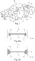
- the body 10 has various structures with cavities, such as pillars 14 and supports or struts 12 .
- Such structural elements 12, 14 with cavities are usually sealed or reinforced with sealing and/or reinforcing elements 16.
- Figures 2a and 2b schematically show a known concept for the sealing and/or reinforcing closure of openings or cavities in a motor vehicle.
- the Figure 2a a device 16 before an expansion of an adhesive 13.
- Figure 2b shows the same device 16 as part of the system 1, but after expansion of the adhesive 13, ie with the expanded adhesive 13'.
- the device 16 is located in a cavity of a body structure, as for example in 1 is shown. A portion of such a structural element 12, 14 of a body is in the Figures 2a and 2b shown schematically.
- the device 16 comprises a carrier 11 which has an edge area 21 .
- the adhesive 13 is essentially arranged on this edge area 21 of the carrier 11 .
- the adhesive 13 Before the expansion of the adhesive 13 there is a gap between the device 16 and the structural element 12,14. This gap allows the structural element 12, 14 to be coated in order to protect the structural element 12, 14 from corrosion. After this coating, the adhesive 13 is usually expanded by the action of heat, the expanded adhesive 13' closing the gap between the device 16 and the structural element 12, 14 as a result. In addition, due to the expansion of the adhesive 13, the device 16' is fixed in the structural element 12, 14 at the same time. A device 16' fastened in the structural element 12, 14 in this way strengthens the structural element 12, 14 on the one hand and closes the cavity in the structural element 12, 14 on the other hand.
- sealing and/or reinforcing elements are relatively complex, complicated and expensive to produce.
- the known sealing and/or reinforcing elements have the disadvantage that they only have a limited shelf life. This is particularly so because the adhesive on the elements cannot be stored for any length of time and cannot be stored under extreme conditions.
- the system should in particular bring economic advantages and also simplify or improve the associated logistics, and in particular the storability.
- a system for insulating a structural element in a motor vehicle comprising: a structural element with a first component and a second component, the components being joined at a first joint and at a second joint, and the structural element having a cavity forms; a device having a carrier, the carrier being arranged on the structural element by a fastening element; and an expandable adhesive disposed on the structural member or on the support by pumping or by extrusion; wherein the carrier and the expandable adhesive are constructed and arranged in such a way that the carrier limits the expandable adhesive in at least one direction when it expands.
- this solution has the advantage that the device can be manufactured in a significantly simpler and more cost-effective manner in comparison to the prior art.
- a one-piece device and/or a device constructed from only one material and/or manufactured in one step can be used.
- a one-component injection molding process can be used instead of a two-component injection molding process. This lowers both the effective costs of manufacture and the expense involved in planning and designing the device.
- a key idea of the present invention is that the expandable adhesive is not placed on the carrier before the device is fixed in the structural element, but that the device is fixed in the structural element without adhesive and the expandable adhesive is introduced into the system separately. This has the advantage that the device is much easier to transport and store without the adhesive. This significantly reduces the associated logistics costs.
- the expandable adhesive can be freshly applied to the system in a production line for the motor vehicle, for example in the form of bulk goods.
- the separate application of the expandable adhesive means that hard-to-reach places in the cavity of the structural element can be reinforced, sealed, dampened or insulated better than is possible with the systems mentioned at the outset.
- the expandable adhesive can completely fill out joints even before it is activated.
- the solution proposed here has the advantage that different structural elements can be insulated with a (standardized) device by using a different quantity and/or arrangement of the expandable adhesive in each case.
- a first structural member with a larger cavity can be insulated with the standard jig and a larger amount of expandable adhesive
- a second structural member with a smaller cavity can be insulated with the same standard jig and a smaller amount of expandable adhesive.
- insulation or "insulated” includes elements or functions or structures or process steps for sealing off and/or closing and/or reinforcing and/or damping and/or insulating a structural element. These different properties of such insulation can occur individually or in combination with one another.
- the structural element comprises at least a first component and a second component, which are joined together at a first joint and at a second joint and thus form a cavity.
- the first and the second component of the structural element can each consist of one element or else of a plurality of elements.
- the structural element can therefore also have more than two joints.
- the system includes multiple devices having a carrier and a fastener.
- the system includes two devices, three devices, four devices, five devices, more than two devices, more than three devices, more than four devices, or more than five devices.
- Both the shape and the materials of these multiple devices can be the same or different.
- the carrier is disposed on the first component of the structural member and the expandable adhesive is disposed on the second component of the structural member.
- the carrier is arranged on the first component of the structural element and the expandable adhesive is also arranged on the first component of the structural element.
- the carrier is arranged on the first component of the structural element, and the expandable adhesive is arranged on the first component and on the second component of the structural element.
- the carrier is arranged on the first component of the structural element and the expandable adhesive is arranged on the carrier.
- the carrier is substantially L-shaped, or an I-shaped, or an H-shaped, or a C-shaped, or a T-shaped, or a W-shaped, or a V-shaped, or a U-shaped, or a N-shaped, or a Z-shaped, or an O-shaped, or a rectangular, or an oval, or a round, or a trapezoidal, or a triangular, or a polygonal cross-section.
- the carrier has a base and a wing.
- the fastener is located on the base and the wing limits expansion of the expandable adhesive in at least one direction.
- the wing forms an angle between 60° and 160° or between 70° and 150° or between 80° and 140° with the base.
- the device or just the carrier is made by an injection molding process.
- the device or only the carrier is produced by a one-component injection molding process.
- the device or just the carrier is made by an extrusion process.
- the carrier and the fastening element are formed in one piece.
- the carrier and the fastening element are formed from the same material.
- the carrier comprises a plastic, in particular polyamide.
- the carrier comprises a fiber-reinforced plastic, in particular a glass-fiber-reinforced or carbon-fiber-reinforced plastic.
- the carrier can consist of different materials.
- Preferred materials are plastics, in particular polyurethanes, polyamides, polyesters and polyolefins, preferably high-temperature-resistant polymers such as poly(phenylene ether), polysulfones or polyether sulfones, which in particular are also foamed; metals, in particular aluminum and steel; or grown organic materials, in particular wood or other (pressed) fiber materials or vitreous or ceramic materials; specifically also foamed materials of this type; or any combination of these materials.
- Polyamide in particular polyamide 6, polyamide 6.6, polyamide 11, polyamide 12 or a mixture thereof is particularly preferably used. Combinations with fibers such as glass fibers or carbon fibers are also possible.
- the carrier can have any construction and any structure.
- it can be solid, hollow, or foamed, or have a lattice-like structure.
- the surface of the support can typically be smooth, rough or textured.
- the device has a substantially circular, or oval, or oblong, or irregularly shaped plan.
- the expandable adhesive has an expansion rate of at least 200%, or at least 300%, or at least 400%, or at least 500%, or at least 800%.
- An example of such an expandable pumpable adhesive is an adhesive available under the tradename Sikaseal® .
- An example of an expandable adhesive that is extrudable is available under the name SikaBaffle® 455.
- the expandable adhesive is arranged in the form of a bead or beads on the second component of the structural element.
- the expandable adhesive is placed onto the second component of the structural member by a robot.
- the at least one bead has a diameter of 2 to 20 mm, or 4 to 18 mm, or 6 to 16 mm.
- the at least one bead has a length of at least 10 mm, or at least 20 mm, or at least 30 mm, or at least 50 mm, or at least 100 mm.
- the expandable adhesive is in contact with the structural element at the first joint and at the second joint.
- the expandable adhesive in the area of the first and the second joint touches both the first component of the structural element and the second component of the structural element.
- the expandable adhesive extends along the second part of the structural element by at least 10 mm or at least 15 mm or at least 20 mm or at least 30 mm or at least 40 mm, starting from the joints.
- the expandable adhesive forms a continuous element between the first joint and the second joint.
- the expandable adhesive forms a single continuous element.
- multiple non-contiguous expandable adhesives form multiple non-contiguous elements.
- the expandable adhesive is a pumpable or extrudable material.
- the expandable adhesive is pumpable at a temperature of less than 80°C, preferably less than 70°C, preferably less than 60°C, more preferably less than 50°C.
- the expandable adhesive is extrudable at a temperature of less than 100°C, preferably less than 90°C, preferably less than 80°C, more preferably less than 70°C.
- the expandable adhesive is pumpable or extrudable at a temperature which is at least 20 K, or at least 30 K, or at least 40 K, or at least 50 K, or at least 60 K below an activation temperature of the second expandable adhesive.
- the fastening element is designed as a clip.
- the fastening element is designed as a welded tab or as a magnetic element or as an adhesive or as a hook.
- the structural element has an opening, with the carrier being arranged such that the opening is free of expanded adhesive after expansion of the expandable adhesive.
- Such an arrangement of the carrier has the advantage that openings in the structural element, such as those used for cable ducts or the like, can be kept free of expanded adhesive, so that such openings are not impaired in their function.
- a distance between the carrier and the structural element is between 2 and 6 mm or between 3 and 5 mm.
- the object set at the outset is also achieved by a method for insulating a structural element in a motor vehicle, the method comprising the steps of: providing a device with a carrier; placing the device on the structural member; placing an expandable adhesive by pumping or by extrusion on the structural member or on the support; joining a first component and a second component of the structural member to form the structural member, the device and the expandable adhesive being disposed in a cavity between the components of the structural member; and expanding the expandable adhesive, wherein the backing limits expansion of the expandable adhesive in at least one direction.
- the expandable adhesive is placed at a temperature of less than 80°C, or less than 70°C, or less than 60°C, or less than 50°C by pumping.
- the expandable adhesive is disposed at a temperature of less than 100°C, or less than 90°C, or less than 80°C, or less than 70°C by extrusion.
- the expandable adhesive is expanded at a temperature greater than 100°C, or greater than 110°C, or greater than 120°C, or greater than 140°C.
- the method is carried out using a system as described above.
- the expandable adhesive is placed onto the structural member or backing by a robot.
- the expandable adhesive is pumped or extruded onto the second component of the structural member.
- the placement of the adhesive on the structural member or the carrier is performed before or after placing the device on the first component of the structural member.
- heat is used when activating the expandable adhesive; in particular, the activation of the adhesive is carried out in a painting oven or in a corrosion protection oven.
- a device 16 in a structural element 12, 14 is shown schematically and by way of example in a cross-sectional illustration.
- the device 16 has a support 11 with an L-shaped cross section.
- a first leg forms a base 17 of the carrier and a second leg forms a wing 18.
- the base 17 and the wing 18 form an angle ⁇ , which in this exemplary embodiment is approximately 90°.
- a fastening element 5 is arranged on the base 17 .
- the device 16 is arranged on the structural element 12 , 14 by this fastening element 5 .
- the fastening element 5 is designed as a clip.
- a distance 4 between the carrier 11 and the structural element 12, 14 is approximately 4 mm in this exemplary embodiment. Such a distance 4 makes it possible, on the one hand, to coat the structural element 12, 14 with a coating liquid before the expandable adhesive expands, and on the other hand allows the carrier 11 on the other hand, to effectively limit an expansion of the expandable adhesive against at least one direction.
- FIGS. 4a and 4b two different devices 16 are shown schematically and by way of example in a spatial representation.
- the device 16 in the Figure 4a is essentially circular in plan.
- the carrier 11 in this exemplary embodiment again has an essentially L-shaped cross section.
- the carrier 11 has a base 17 and a wing 18 which form an angle 9 .
- three fastening elements 5 are arranged on the base 17 for arranging the device 16 on a structural element.
- the device 16 in Figure 4b has a rectangular cross section.
- the device 16 is elongate or has an elongate outline.
- the support 11 of the device 16 has a base 17 and a wing 18 which form an angle ⁇ .
- the base 17 and the wing 18 are supplemented by further walls of the support 11.
- two fastening elements 5 for arranging the device 16 in a structural element are arranged on the base 17 of the carrier 11 .
- a system 1 is shown, wherein the expandable adhesive 13 is arranged on the structural element 12,14.
- the expandable adhesive 13 is arranged on a first component 12.1, 14.1 of the structural element and the device 16 is arranged on a second component 12.2, 14.2 of the structural element.
- the two components 12.1, 14.1, 12.2, 14.2 of the structural element are joined together at a first joint 6 and at a second joint 7.
- the structural element 12, 14 forms a cavity 3 in which both the expandable adhesive 13 and the device 16 are arranged.
- the device 16 comprises a support 11 and a fastener 5.
- the support 11 has a base 17 and a wing 18 which form an angle ⁇ .
- the wing 18 is arranged in front of an opening 8 in the structural element 12, 14.
- the carrier 11 and in particular its wings 18 limit the expansion of the expandable adhesive 13 in the direction of this opening 8, so that the expanded adhesive 13' cannot reach the region of the opening 8. This is in Figure 5b 1, in which the system 1' is shown after expansion of the expandable adhesive 13.
- FIGs 6a and 6b another exemplary system 1 for insulating a structural element 12, 14 is shown.
- the expandable adhesive 13 is not arranged on the structural element 12, 14 but on the carrier 11.
- the expandable adhesive 13 is in the form of a bead and is arranged on the carrier 11 by pumping or extrusion.
- the carrier 11 limits an expansion of the expandable adhesive 13 in at least one direction, so that a predetermined area of the structural element 12, 14 or its cavity 3 remains free of expanded adhesive 13' after an expansion of the expandable adhesive 13. This is in the Figure 6b shown.
Landscapes
- Engineering & Computer Science (AREA)
- Mechanical Engineering (AREA)
- Chemical & Material Sciences (AREA)
- Combustion & Propulsion (AREA)
- Transportation (AREA)
- Architecture (AREA)
- Structural Engineering (AREA)
- Acoustics & Sound (AREA)
- Physics & Mathematics (AREA)
- Standing Axle, Rod, Or Tube Structures Coupled By Welding, Adhesion, Or Deposition (AREA)
- Body Structure For Vehicles (AREA)
- Connection Of Plates (AREA)
- Element Separation (AREA)
- Thin Film Transistor (AREA)
- Bipolar Transistors (AREA)
- Insulation, Fastening Of Motor, Generator Windings (AREA)
- Railway Tracks (AREA)
Abstract
Description
- Die Erfindung betrifft ein System zur Dämmung eines Strukturelementes in einem Kraftfahrzeug. Sie betrifft des Weiteren ein Verfahren zur Dämmung eines Strukturelementes in einem Kraftfahrzeug.
- Vielfach weisen Bauelemente, wie beispielsweise Karosserien und/oder Rahmen von Transport- und Fortbewegungsmitteln, insbesondere von Fahrzeugen zu Wasser oder zu Land oder von Luftfahrzeugen, Strukturen mit Hohlräumen auf, um leichtgewichtige Konstruktionen zu ermöglichen. Diese Hohlräume verursachen jedoch verschiedenste Probleme. Je nach Art des Hohlraumes muss dieser zum Verhindern des Eindringens von Feuchtigkeit und Verschmutzungen, die zur Korrosion der Bauelemente führen können, abgedichtet werden. Oft ist es auch wünschenswert, die Hohlräume und somit das Bauelement wesentlich zu verstärken, jedoch das geringe Gewicht beizubehalten. Oft ist es auch notwendig, die Hohlräume und somit die Bauelemente zu stabilisieren, um Geräusche, die sonst den Hohlraum entlang oder durch diesen hindurch übertragen werden würden, zu reduzieren. Viele dieser Hohlräume weisen eine unregelmässige Form oder ein enges Ausmass auf, wodurch es erschwert wird, sie richtig abzudichten, zu verstärken und zu dämpfen.
- Insbesondere im Automobilbau, aber auch im Flugzeug- und Bootsbau, werden deshalb Abdichtungselemente (Englisch: baffle) verwendet, um Hohlräume abzudichten und/ oder akustisch abzuschotten, oder Verstärkungselemente (Englisch: reinforcer) verwendet, um Hohlräume zu verstärken.
- In
Fig. 1 ist eine Karosserie eines Automobils schematisch dargestellt. Die Karosserie 10 weist dabei verschiedene Strukturen mit Hohlräumen, wie beispielsweise Säulen 14 und Träger bzw. Verstrebungen 12 auf. Solche Strukturelemente 12, 14 mit Hohlräumen werden üblicherweise mit Abdichtungs- und/oder Verstärkungselementen 16 abgedichtet bzw. verstärkt. -
Fig. 2a und 2b zeigen schematisch ein bekanntes Konzept zum abdichtenden und/oder verstärkenden Verschluss von Öffnungen bzw. Hohlräumen in einem Kraftfahrzeug. Dabei zeigt dieFig. 2a eine Vorrichtung 16 vor einer Expansion eines Klebstoffes 13.Fig. 2b zeigt dieselbe Vorrichtung 16 als Bestandteil des Systems 1, jedoch nach einer Expansion des Klebstoffes 13, also mit dem expandierten Klebstoff 13'. - Die Vorrichtung 16 befindet sich in einem Hohlraum einer Karosseriestruktur, wie sie beispielsweise in
Fig. 1 dargestellt ist. Ein Abschnitt eines solchen Strukturelements 12, 14 einer Karosserie ist in denFig. 2a und 2b schematisch dargestellt. Die Vorrichtung 16 umfasst einen Träger 11, welcher einen Randbereich 21 hat. Der Klebstoff 13 ist dabei im Wesentlichen auf diesem Randbereich 21 des Trägers 11 angeordnet. - Vor der Expansion des Klebstoffes 13 besteht zwischen der Vorrichtung 16 und dem Strukturelement 12, 14 ein Spalt. Dieser Spalt erlaubt es, das Strukturelement 12, 14 zu beschichten, um einen Korrosionsschutz des Strukturelementes 12, 14 zu erreichen. Nach dieser Beschichtung wird der Klebstoff13 üblicherweise durch eine Wärmeeinwirkung expandiert, wobei der expandierte Klebstoff 13' dadurch den Spalt zwischen der Vorrichtung 16 und dem Strukturelement 12, 14 schliesst. Zudem wird durch die Expansion des Klebstoffes 13 auch zugleich eine Fixierung der Vorrichtung 16' im Strukturelement 12, 14 erreicht. Eine derart im Strukturelement 12, 14 befestigte Vorrichtung 16' verstärkt einerseits das Strukturelement 12, 14 und verschliesst andererseits den Hohlraum im Strukturelement 12, 14.
- Nachteilig an den bisher bekannten Abdichtungs- und/oder Verstärkungselementen ist es, dass diese Elemente relativ komplex, aufwändig und kostenintensiv in der Herstellung sind.
- Weiterhin haben die bekannten Abdichtungs- und/oder Verstärkungselemente den Nachteil, dass sie eine lediglich beschränkte Lagerfähigkeit aufweisen. Dies ist insbesondere deshalb so, weil der Klebstoff auf den Elementen nicht beliebig lang und nicht bei extremen Bedingungen gelagert werden kann.
- Es ist daher eine Aufgabe der vorliegenden Erfindung, ein verbessertes System zur Dämmung eines Strukturelementes in einem Kraftfahrzeug zur Verfügung zu stellen, welches die Nachteile des Standes der Technik vermeidet. Das System soll insbesondere wirtschaftliche Vorteile mit sich bringen und zudem die damit verbundene Logistik, und insbesondere die Lagerfähigkeit, vereinfachen bzw. verbessern.
- Diese Aufgabe wird gelöst durch ein System zur Dämmung eines Strukturelementes in einem Kraftfahrzeug, das System umfassend: ein Strukturelement mit einem ersten Bestandteil und einem zweiten Bestandteil, wobei die Bestandteile an einer ersten Fügestelle und an einer zweiten Fügestelle zusammengefügt sind, und wobei das Strukturelement einen Hohlraum bildet; eine Vorrichtung mit einem Träger, wobei der Träger durch ein Befestigungselement am Strukturelement angeordnet ist; und ein expandierbarer Klebstoff, welcher auf dem Strukturelement oder auf dem Träger durch Pumpen oder durch Extrudieren angeordnet ist; wobei der Träger und der expandierbare Klebstoff derart ausgebildet und angeordnet sind, dass der Träger den expandierbaren Klebstoff bei dessen Expansion in zumindest eine Richtung begrenzt.
- Diese Lösung hat zunächst den Vorteil, dass dadurch die Vorrichtung im Vergleich zum Stand der Technik wesentlich einfacher und kostengünstiger hergestellt werden kann. Insbesondere kann gemäss dem hier vorgeschlagenen System eine einstückige und/oder aus nur einem Material aufgebaute und/oder in einem Schritt hergestellte Vorrichtung eingesetzt werden. Somit kann beispielsweise ein Einkomponenten-Spritzgussverfahren anstelle eines Zweikomponenten-Spritzgussverfahrens verwendet werden. Dies senkt sowohl die effektiven Kosten der Herstellung als auch einen Aufwand bei der Planung und Ausgestaltung der Vorrichtung.
- Ein Kerngedanke der vorliegenden Erfindung besteht darin, dass der expandierbare Klebstoff nicht auf dem Träger angeordnet ist, bevor die Vorrichtung im Strukturelement befestigt wird, sondern dass die Vorrichtung ohne Klebstoff im Strukturelement befestigt wird und der expandierbare Klebstoff separat in das System eingebracht wird. Dies hat den Vorteil, dass die Vorrichtung ohne den Klebstoff viel besser transportfähig und lagerfähig ist. Dies reduziert damit verbundene Logistikkosten wesentlich. Dabei kann der expandierbare Klebstoff in einer Produktionslinie der Kraftfahrzeuge jeweils frisch in das System appliziert werden, beispielsweise in der Form von Bulkware.
- Ein weiterer Vorteil des hier vorgeschlagenen Systems ist darin zu sehen, dass durch die separate Applikation des expandierbaren Klebstoffes schwer zugängliche Stellen des Hohlraumes des Strukturelementes besser verstärkt, abgedichtet, gedämpft oder gedämmt werden können, als dies mit den eingangs erwähnten Systemen möglich ist. Insbesondere kann der expandierbare Klebstoff auch schon vor dessen Aktivierung Fügestellen vollständig ausfüllen.
- Weiterhin hat die hier vorgeschlagene Lösung den Vorteil, dass mit einer (standardisierten) Vorrichtung verschiedene Strukturelemente gedämmt werden können, indem jeweils eine unterschiedliche Menge und/oder Anordnung des expandierbaren Klebstoffes eingesetzt wird. So kann beispielsweise ein erstes Strukturelement mit einem grösseren Hohlraum mit der Standardvorrichtung und einer grösseren Menge an expandierbarem Klebstoff gedämmt werden, und ein zweites Strukturelement mit einem kleineren Hohlraum kann mit derselben Standardvorrichtung und einer kleineren Menge an expandierbarem Klebstoff gedämmt werden.
- Somit müssen weniger verschiedene Vorrichtungen hergestellt werden, sodass durch höhere Stückzahlen, weniger Werkzeuge, und einfachere Logistik die Gesamtkosten des Systems verringert werden können.
- Die Bezeichnung "Dämmung" bzw. "gedämmt" umfasst im Zusammenhang mit dieser Erfindung Elemente bzw. Funktionen bzw. Strukturen bzw. Verfahrensschritte zur Abschottung und/oder Verschliessung und/oder Verstärkung und/oder Dämpfung und/oder Dämmung eines Strukturelementes. Diese verschiedenen Eigenschaften einer solchen Dämmung können dabei einzeln oder aber in Kombination miteinander auftreten.
- Das Strukturelement umfasst zumindest einen ersten Bestanteil und einen zweiten Bestandteil, welche an einer ersten Fügestelle und an einer zweiten Fügestelle zusammengefügt sind und so einen Hohlraum bilden. Dabei können der erste und der zweite Bestandteil des Strukturelementes jeweils aus einem Element oder aber aus mehreren Elementen bestehen. Daher kann das Strukturelement auch mehr als zwei Fügestellen aufweisen.
- In einer beispielhaften Ausführungsform umfasst das System mehrere Vorrichtungen mit einem Träger und einem Befestigungselement. Beispielsweise umfasst das System zwei Vorrichtung, drei Vorrichtungen, vier Vorrichtungen, fünf Vorrichtungen, mehr als zwei Vorrichtungen, mehr als drei Vorrichtungen, mehr als vier Vorrichtungen, oder mehr als fünf Vorrichtungen.
- Dabei können jeweils sowohl die Gestalt sowie auch die Materialien dieser mehreren Vorrichtungen gleich oder unterschiedlich sein.
- In einer beispielhaften Ausführungsform ist der Träger am ersten Bestandteil des Strukturelementes angeordnet, und der expandierbare Klebstoff ist auf dem zweiten Bestandteil des Strukturelementes angeordnet.
- In einer alternativen Ausführungsform ist der Träger am ersten Bestandteil des Strukturelementes angeordnet, und der expandierbare Klebstoff ist ebenfalls auf dem ersten Bestandteil des Strukturelementes angeordnet.
- In einer alternativen Weiterbildung ist der Träger am ersten Bestandteil des Strukturelementes angeordnet, und der expandierbare Klebstoff ist auf dem ersten Bestandteil und auf dem zweiten Bestandteil des Strukturelementes angeordnet.
- In einer weiteren alternativen Ausführungsform ist der Träger am ersten Bestandteil des Strukturelementes angeordnet, und der expandierbare Klebstoff ist auf dem Träger angeordnet.
- In einer beispielhaften Ausführungsform hat der Träger im Wesentlichen einen L-förmigen oder einen I-förmigen oder einen H-förmigen oder einen C-förmigen oder einen T-förmigen oder einen W-förmigen oder einen V-förmigen oder einen U-förmigen oder einen N-förmigen oder einen Z-förmigen oder einen O-förmigen oder einen rechteckigen oder einen ovalen oder einen runden oder einen trapezförmigen oder einen dreieckigen oder einen vieleckigen Querschnitt.
- In einer beispielhaften Ausführungsform hat der Träger eine Basis und einen Flügel.
- In einer beispielhaften Weiterbildung ist das Befestigungselement an der Basis angeordnet und der Flügel begrenzt die Expansion des expandierbaren Klebstoffes in zumindest eine Richtung.
- In einer beispielhaften Weiterbildung bildet der Flügel mit der Basis einen Winkel zwischen 60° und 160° oder zwischen 70° und 150° oder zwischen 80° und 140°.
- In einer beispielhaften Ausführungsform ist die Vorrichtung oder nur der Träger durch ein Spritzgussverfahren hergestellt.
- In einer beispielhaften Weiterbildung ist die Vorrichtung oder nur der Träger durch ein Einkomponenten-Spritzgussverfahren hergestellt.
- In einer alternativen Ausführungsform ist die Vorrichtung oder nur der Träger durch eine Extrusionsverfahren hergestellt.
- In einer beispielhaften Ausführungsform sind der Träger und das Befestigungselement einstückig ausgebildet.
- In einer weiteren beispielhaften Ausführungsform sind der Träger und das Befestigungselement aus demselben Material ausgebildet.
- In einer beispielhaften Ausführungsform umfasst der Träger einen Kunststoff, insbesondere Polyamid.
- In einer beispielhaften Ausführungsform umfasst der Träger einen faserverstärkten Kunststoff, insbesondere einen glasfaserverstärkten oder karbonfaserverstärkten Kunststoff.
- Der Träger kann grundsätzlich aus verschiedenen Materialien bestehen. Bevorzugte Materialien sind Kunststoffe, insbesondere Polyurethane, Polyamide, Polyester und Polyolefine, bevorzugt hochtemperaturbeständige Polymere wie Poly(phenylenether), Polysulfone oder Polyethersulfone, welche insbesondere auch geschäumt sind; Metalle, insbesondere Aluminium und Stahl; oder gewachsene organische Materialien, insbesondere Holz- oder andere (gepresste) Faserwerkstoffe oder glasartige oder keramische Materialien; speziell auch geschäumte Materialien dieser Art; oder beliebige Kombinationen dieser Materialien. Besonders bevorzugt wird Polyamid, insbesondere Polyamid 6, Polyamid 6,6, Polyamid 11, Polyamid 12 oder ein Gemisch davon verwendet. Auch Kombinationen mit Fasern, wie beispielsweise Glasfasern oder Karbonfasern, sind möglich.
- Weiterhin kann der Träger einen beliebigen Aufbau und eine beliebige Struktur aufweisen. Er kann beispielsweise massiv, hohl, oder geschäumt sein oder eine gitterartige Struktur aufweisen. Die Oberfläche des Trägers kann typischerweise glatt, rau oder strukturiert sein.
- In einer beispielhaften Ausführungsform hat die Vorrichtung einen im Wesentlichen kreisförmigen oder ovalen oder länglichen oder unregelmässig geformten Grundriss.
- In einer beispielhaften Ausführungsform hat der expandierbare Klebstoff eine Expansionsrate von zumindest 200% oder von zumindest 300% oder von zumindest 400% oder von zumindest 500% oder von zumindest 800%.
- Ein solcher expandierbarer und pumpbarer Klebstoff ist beispielhaft in der Europäischen Patentanmeldung
EP 3 281 970 A1 beschrieben. - Ein Beispiel für einen solchen expandierbaren pumpbaren Klebstoff ist ein unter dem Handelsnamen Sikaseal® erhältlicher Klebstoff.
- Ein Beispiel für einen expandierbaren Klebstoff, welcher extrudierbar ist, ist unter dem Namen SikaBaffle® 455 erhältlich.
- In einer beispielhaften Ausführungsform ist der expandierbare Klebstoff in Form einer Raupe oder mehrerer Raupen auf dem zweiten Bestandteil des Strukturelementes angeordnet.
- In einer beispielhaften Ausführungsform ist der expandierbare Klebstoff durch einen Roboter auf dem zweiten Bestandteil des Strukturelementes angeordnet.
- In einer beispielhaften Ausführungsform hat die zumindest eine Raupe einen Durchmesser von 2 bis 20 mm oder von 4 bis 18 mm oder von 6 bis 16 mm.
- In einer beispielhaften Ausführungsform hat die zumindest eine Raupe eine Länge von zumindest 10 mm oder von zumindest 20 mm oder von zumindest 30 mm oder von zumindest 50 mm oder von zumindest 100 mm.
- In einer beispielhaften Ausführungsform ist der expandierbare Klebstoff an der ersten Fügestelle und an der zweiten Fügestelle mit dem Strukturelement in Kontakt.
- In einer beispielhaften Ausführungsform berührt der expandierbare Klebstoff im Bereich der ersten und der zweiten Fügestelle jeweils sowohl den ersten Bestandteil des Strukturelementes als auch den zweiten Bestandteil des Strukturelementes.
- In einer beispielhaften Ausführungsform hat der expandierbare Klebstoff jeweils ausgehend von den Fügestellen eine Ausdehnung entlang des zweiten Bestandteils des Strukturelementes von zumindest 10 mm oder von zumindest 15 mm oder von zumindest 20 mm oder von zumindest 30 mm oder von zumindest 40 mm.
- In einer beispielhaften Ausführungsform bildet der expandierbare Klebstoff ein durchgehendes Element zwischen der ersten Fügestelle und der zweiten Fügestelle.
- In einer beispielhaften Ausführungsform bildet der expandierbare Klebstoff ein einziges zusammenhängendes Element. In einer alternativen Ausführungsform bilden mehrere nicht zusammenhängende expandierbare Klebstoffe mehrere nicht zusammenhängende Elemente.
- In einer beispielhaften Ausführungsform ist der expandierbare Klebstoff ein pumpbares oder extrudierbares Material.
- In einer beispielhaften Ausführungsform ist der expandierbare Klebstoff pumpbar bei einer Temperatur von weniger als 80° C, bevorzugt von weniger als 70° C, bevorzugt von weniger als 60° C, besonders bevorzugt von weniger als 50° C.
- In einer beispielhaften Ausführungsform ist der expandierbare Klebstoff extrudierbar bei einer Temperatur von weniger als 100° C, bevorzugt von weniger als 90°C, bevorzugt von weniger als 80°C, besonders bevorzugt von weniger als 70°C.
- In einer beispielhaften Ausführungsform ist der expandierbare Klebstoff pumpbar oder extrudierbar bei einer Temperatur, welche um zumindest 20 K oder um zumindest 30 K oder um zumindest 40 K oder um zumindest 50 K oder um zumindest 60 K unter einer Aktivierungstemperatur des zweiten expandierbare Klebstoffes liegt.
- In einer beispielhaften Ausführungsform ist das Befestigungselement als Clip ausgebildet.
- In einer alternativen Ausführungsform ist das Befestigungselement als Schweisslasche oder als magnetisches Element oder als Klebstoff oder als Haken ausgebildet.
- In einer beispielhaften Ausführungsform hat das Strukturelement eine Öffnung, wobei der Träger derart angeordnet ist, dass die Öffnung nach einer Expansion des expandierbaren Klebstoffes frei ist von expandiertem Klebstoff.
- Eine solche Anordnung des Trägers hat den Vorteil, dass dadurch Öffnungen im Strukturelement, wie sie beispielsweise für Kabeldurchführungen oder Ähnliches verwendet werden, freigehalten werden können von expandiertem Klebstoff, so dass solche Öffnungen in ihrer Funktion nicht beeinträchtigt sind.
- In einer beispielhaften Ausführungsform beträgt eine Distanz zwischen dem Träger und dem Strukturelement zwischen 2 und 6 mm oder zwischen 3 und 5 mm.
- Die eingangs gestellte Aufgabe wird zudem gelöst durch ein Verfahren zur Dämmung eines Strukturelementes in einem Kraftfahrzeug, das Verfahren umfassend die Schritte: Bereitstellen einer Vorrichtung mit einem Träger; Anordnen der Vorrichtung am Strukturelement; Anordnen eines expandierbaren Klebstoffes durch Pumpen oder durch Extrudieren auf dem Strukturelement oder auf dem Träger; Fügen eines ersten Bestandteils und eines zweiten Bestandteils des Strukturelementes zur Bildung des Strukturelementes, wobei die Vorrichtung und der expandierbare Klebstoff in einem Hohlraum zwischen den Bestandteilen des Strukturelementes angeordnet sind; und Expandieren des expandierbaren Klebstoffes, wobei der Träger die Expansion des expandierbaren Klebstoffes in zumindest eine Richtung begrenzt.
- In einer beispielhaften Ausführungsform wird der expandierbare Klebstoff mit einer Temperatur von weniger als 80°C oder von weniger als 70°C oder von weniger als 60°C oder von weniger als 50°C durch Pumpen angeordnet.
- In einer beispielhaften Ausführungsform wird der expandierbare Klebstoff mit einer Temperatur von weniger als 100°C oder von weniger als 90°C oder von weniger als 80°C oder von weniger als 70°C durch Extrudieren angeordnet.
- In einer beispielhaften Ausführungsform wird der expandierbare Klebstoff mit einer Temperatur von mehr als 100°C oder von mehr als 110°C oder von mehr als 120°C oder von mehr als 140°C expandiert.
- In einer beispielhaften Ausführungsform wird das Verfahren mit einem System gemäss obiger Beschreibung durchgeführt.
- In einer beispielhaften Ausführungsform wird der expandierbare Klebstoff durch einen Roboter auf dem Strukturelement oder dem Träger angeordnet.
- In einer beispielhaften Ausführungsform wird der expandierbare Klebstoff auf den zweiten Bestandteil des Strukturelementes gepumpt oder extrudiert.
- In einer beispielhaften Ausführungsform wird die Anordnung des Klebstoffes auf dem Strukturelement oder dem Träger vor oder nach dem Anordnen der Vorrichtung an dem ersten Bestandteil des Strukturelementes durchgeführt.
- In einer beispielhaften Ausführungsform wird beim Aktivieren des expandierbaren Klebstoffes Wärme eingesetzt, insbesondere wird die Aktivierung des Klebstoffes in einem Lackierofen oder in einem Korrosionsschutz-Ofen durchgeführt.
- Einzelheiten und Vorteile der Erfindung werden im Folgenden anhand von Ausführungsbeispielen und mit Bezug auf schematische Zeichnungen beschrieben.
- Es zeigen:
- Fig. 1
- eine beispielhafte Darstellung einer Karosserie gemäss Stand der Technik;
- Fig. 2a und 2b
- schematische Darstellung einer beispielhaften Vorrichtung gemäss Stand der Technik;
- Fig. 3
- schematische Darstellung einer beispielhaften Vorrichtung in einem Strukturelement;
- Fig. 4a und 4b
- schematische Darstellungen beispielhafter Vorrichtungen; und
- Fig. 5a bis 6b
- schematische Darstellungen beispielhafter Systeme zur Dämmung von Strukturelementen.
- In
Fig. 3 ist schematisch und beispielhaft eine Vorrichtung 16 in einem Strukturelement 12, 14 in einer Querschnittsdarstellung gezeigt. In diesem Ausführungsbeispiel hat die Vorrichtung 16 einen Träger 11 mit einem L-förmigen Querschnitt. Dabei bildet ein erster Schenkel eine Basis 17 des Trägers, und ein zweiter Schenkel bildet einen Flügel 18. Die Basis 17 und der Flügel 18 bilden einen Winkel 9, welcher in diesem Ausführungsbeispiel ungefähr 90° beträgt. An der Basis 17 ist ein Befestigungselement 5 angeordnet. Die Vorrichtung 16 ist durch dieses Befestigungselement 5 am Strukturelement 12, 14 angeordnet. In diesem Ausführungsbeispiel ist das Befestigungselement 5 als Clip ausgebildet. - Eine Distanz 4 zwischen dem Träger 11 und dem Strukturelement 12, 14 beträgt in diesem Ausführungsbeispiel ungefähr 4 mm. Eine solche Distanz 4 ermöglicht es einerseits, das Strukturelement 12, 14 vor einer Expansion des expandierbaren Klebstoffes mit einer Lackierflüssigkeit zu beschichten, und erlaubt es dem Träger 11 andererseits, eine Expansion des expandierbaren Klebstoffes gegen zumindest eine Richtung hin effektiv zu begrenzen.
- In den
Fig. 4a und 4b sind schematisch und beispielhaft zwei unterschiedliche Vorrichtungen 16 in räumlicher Darstellung abgebildet. Die Vorrichtung 16 in derFig. 4a hat einen im Wesentlichen kreisförmigen Grundriss. Zudem hat der Träger 11 in diesem Ausführungsbeispiel wiederum einen im Wesentlichen L-förmigen Querschnitt. Dabei hat der Träger 11 eine Basis 17 und einen Flügel 18, welche einen Winkel 9 bilden. In diesem Ausführungsbeispiel sind an der Basis 17 drei Befestigungselemente 5 zur Anordnung der Vorrichtung 16 an einem Strukturelement angeordnet. - Die Vorrichtung 16 in
Fig. 4b hat einen rechteckigen Querschnitt. Dabei ist die Vorrichtung 16 länglich ausgebildet bzw. sie hat einen länglichen Grundriss. Wiederum hat der Träger 11 der Vorrichtung 16 eine Basis 17 und einen Flügel 18, welche einen Winkel 9 bilden. In diesem Ausführungsbeispiel sind die Basis 17 und der Flügel 18 durch weitere Wände des Trägers 11 ergänzt. An der Basis 17 des Trägers 11 sind in diesem Ausführungsbeispiel zwei Befestigungselemente 5 zur Anordnung der Vorrichtung 16 in einem Strukturelement angeordnet. - In den
Fig. 5a bis 6b sind schematisch und beispielhaft Systeme 1 zur Dämmung eines Strukturelementes 12, 14 dargestellt. - In den
Fig. 5a und 5b ist ein System 1 dargestellt, wobei der expandierbare Klebstoff 13 auf dem Strukturelement 12, 14 angeordnet ist. In diesem Ausführungsbeispiel ist der expandierbare Klebstoff 13 auf einem ersten Bestandteil 12.1, 14.1 des Strukturelementes angeordnet, und die Vorrichtung 16 ist auf einem zweiten Bestandteil 12.2, 14.2 des Strukturelementes angeordnet. Die beiden Bestandteile 12.1, 14.1, 12.2, 14.2 des Strukturelementes sind an einer ersten Fügestelle 6 und an einer zweiten Fügestelle 7 zusammengefügt. Dabei bildet das Strukturelement 12, 14 einen Hohlraum 3, in welchem sowohl der expandierbare Klebstoff 13 als auch die Vorrichtung 16 angeordnet sind. - Die Vorrichtung 16 umfasst einen Träger 11 und ein Befestigungselement 5. Der Träger 11 hat eine Basis 17 und einen Flügel 18, welche einen Winkel 9 bilden. Der Flügel 18 ist dabei vor einer Öffnung 8 im Strukturelement 12, 14 angeordnet. Dadurch begrenzt der Träger 11 und insbesondere dessen Flügel 18 die Expansion des expandierbaren Klebstoffes 13 in Richtung dieser Öffnung 8, so dass der expandierte Klebstoff 13' nicht in den Bereich der Öffnung 8 gelangen kann. Dies ist in
Fig. 5b ersichtlich, in welcher das System 1' nach einer Expansion des expandierbaren Klebstoffes 13 dargestellt ist. - In den
Fig. 6a und 6b ist ein weiteres beispielhaftes System 1 zur Dämmung eines Strukturelementes 12, 14 dargestellt. Im Unterschied zum System 1 in denFig. 5a und 5b ist in diesem Ausführungsbeispiel der expandierbare Klebstoff 13 nicht auf dem Strukturelement 12, 14 angeordnet, sondern auf dem Träger 11. Dabei ist der expandierbare Klebstoff 13 in der Form einer Raupe und durch Pumpen oder Extrudieren auf dem Träger 11 angeordnet. - Wiederum begrenzt der Träger 11 eine Expansion des expandierbaren Klebstoffes 13 in zumindest eine Richtung, so dass ein vorbestimmter Bereich des Strukturelementes 12, 14 bzw. dessen Hohlraum 3 nach einer Expansion des expandierbaren Klebstoffes 13 frei bleibt von expandiertem Klebstoff 13'. Dies ist in der
Fig. 6b dargestellt. -
- 1
- System
- 3
- Hohlraum
- 4
- Distanz
- 5
- Befestigungselement
- 6
- erste Fügestelle
- 7
- zweite Fügestelle
- 8
- Öffnung
- 9
- Winkel
- 10
- Karosserie
- 11
- Träger
- 12
- Strukturelement
- 12.1
- erster Bestandteil
- 12.2
- zweiter Bestandteil
- 13
- expandierbarer Klebstoff
- 14
- Strukturelement
- 14.1
- erster Bestandteil
- 14.2
- zweiter Bestandteil
- 16
- Vorrichtung
- 17
- Basis
- 18
- Flügel
- 21
- Randbereich
Claims (15)
- System (1) zur Dämmung eines Strukturelementes (12, 14) in einem Kraftfahrzeug, das System (1) umfassend:ein Strukturelement (12, 14) mit einem ersten Bestandteil (12.1, 14.1) und einem zweiten Bestandteil (12.2, 14.2), wobei die Bestandteile (12.1, 12.2, 14.1, 14.2) an einer ersten Fügestelle (6) und an einer zweiten Fügestelle (7) zusammengefügt sind, und wobei das Strukturelement (12, 14) einen Hohlraum (3) bildet;eine Vorrichtung (16) mit einem Träger (11), wobei der Träger (11) durch ein Befestigungselement (5) am Strukturelement (12, 14) angeordnet ist; undein expandierbarer Klebstoff (13), welcher auf dem Strukturelement (12, 14) oder auf dem Träger (11) durch Pumpen oder durch Extrudieren angeordnet ist;wobei der Träger (11) und der expandierbare Klebstoff (13) derart ausgebildet und angeordnet sind, dass der Träger (11) den expandierbaren Klebstoff (13) bei dessen Expansion in zumindest eine Richtung begrenzt.
- System nach Anspruch 1, wobei der Träger (11) am ersten Bestandteil (12.1, 14.1) des Strukturelementes (12, 14) angeordnet ist, und wobei der expandierbare Klebstoff (13) auf dem zweiten Bestandteil (12.2, 14.2) des Strukturelementes (12, 14) angeordnet ist.
- System nach einem der Ansprüche 1 oder 2, wobei der Träger (11) eine Basis (17) und einen Flügel (18) hat, und wobei das Befestigungselement an der Basis (17) angeordnet ist und der Flügel (18) die Expansion des expandierbaren Klebstoffes (13) in zumindest eine Richtung begrenzt.
- System (1) nach Anspruch 3, wobei der Flügel (18) und die Basis (17) einen Winkel zwischen 60° und 160° bilden.
- System nach einem der vorhergehenden Ansprüche, wobei die Vorrichtung (16) durch ein Spritzgussverfahren hergestellt ist und/oder wobei die Vorrichtung (16) aus nur einem Material besteht und/oder wobei die Vorrichtung (16) einstückig ausgebildet ist.
- System nach einem der vorhergehenden Ansprüche, wobei die Vorrichtung (16) einen im Wesentlichen kreisförmigen oder ovalen oder länglichen oder unregelmässig geformten Grundriss hat.
- System nach einem der vorhergehenden Ansprüche, wobei der expandierbare Klebstoff (13) eine Expansionsrate von zumindest 200% hat.
- System nach einem der vorhergehenden Ansprüche, wobei der expandierbare Klebstoff (13) in Form einer Raupe oder mehrerer Raupen auf dem Strukturelement (12, 14) oder auf dem Träger (11) angeordnet ist.
- System nach einem der vorhergehenden Ansprüche, wobei der expandierbare Klebstoff (13) als ein zusammenhängendes Element oder als mehrere nicht zusammenhängende Elemente ausgebildet ist.
- System nach einem der vorhergehenden Ansprüche, wobei das Befestigungselement (5) als Clip ausgebildet ist.
- System nach einem der vorhergehenden Ansprüche, wobei das Strukturelement (12, 14) eine Öffnung (8) hat, und wobei der Träger (11) derart angeordnet ist, dass die Öffnung (8) nach einer Expansion des expandierbaren Klebstoffes (13) frei ist von expandiertem Klebstoff (13').
- System (1) nach einem der vorhergehenden Ansprüche, wobei eine Distanz (4) zwischen dem Träger (11) und dem Strukturelement (12, 14) zwischen 2 und 6 mm beträgt.
- Verfahren zur Dämmung eines Strukturelementes (12, 14) in einem Kraftfahrzeug, das Verfahren umfassend die Schritte:Bereitstellen einer Vorrichtung (16) mit einem Träger (11);Anordnen der Vorrichtung (16) am Strukturelement (12, 14);Anordnen eines expandierbaren Klebstoffes (13) durch Pumpen oder durch Extrudieren auf dem Strukturelement (12, 14) oder auf dem Träger (11);Fügen eines ersten Bestandteils (12.1, 14.1) und eines zweiten Bestandteils (12.2, 14.2) des Strukturelementes (12, 14) zur Bildung des Strukturelementes (12, 14),wobei die Vorrichtung (16) und der expandierbare Klebstoff (13) in einem Hohlraum (3) zwischen den Bestandteilen (12.1, 12.2) des Strukturelementes (12, 14) angeordnet sind; undExpandieren des expandierbaren Klebstoffes (13), wobei der Träger (11) die Expansion des expandierbaren Klebstoffes (13) in zumindest eine Richtung begrenzt.
- Verfahren nach Anspruch 13, wobei der expandierbare Klebstoff (13) mit einer Temperatur von weniger als 80°C durch Pumpen oder durch Extrudieren angeordnet wird und/oder wobei der expandierbare Klebstoff (13) mit einer Temperatur von mehr als 100°C expandiert wird.
- Verfahren nach Anspruch 13 oder 14, wobei das Verfahren mit einem System (1) nach einem der Ansprüche 1 bis 13 durchgeführt wird.
Applications Claiming Priority (3)
| Application Number | Priority Date | Filing Date | Title |
|---|---|---|---|
| EP18192073 | 2018-08-31 | ||
| EP19758417.0A EP3844051B1 (de) | 2018-08-31 | 2019-08-27 | System zu dämmung eines strukturelementes |
| PCT/EP2019/072884 WO2020043739A1 (de) | 2018-08-31 | 2019-08-27 | System zu dämmung eines strukturelementes |
Related Parent Applications (2)
| Application Number | Title | Priority Date | Filing Date |
|---|---|---|---|
| EP19758417.0A Division EP3844051B1 (de) | 2018-08-31 | 2019-08-27 | System zu dämmung eines strukturelementes |
| EP19758417.0A Division-Into EP3844051B1 (de) | 2018-08-31 | 2019-08-27 | System zu dämmung eines strukturelementes |
Publications (2)
| Publication Number | Publication Date |
|---|---|
| EP4223618A2 true EP4223618A2 (de) | 2023-08-09 |
| EP4223618A3 EP4223618A3 (de) | 2023-08-23 |
Family
ID=63490234
Family Applications (2)
| Application Number | Title | Priority Date | Filing Date |
|---|---|---|---|
| EP23166716.3A Pending EP4223618A3 (de) | 2018-08-31 | 2019-08-27 | System zu dämmung eines strukturelementes |
| EP19758417.0A Active EP3844051B1 (de) | 2018-08-31 | 2019-08-27 | System zu dämmung eines strukturelementes |
Family Applications After (1)
| Application Number | Title | Priority Date | Filing Date |
|---|---|---|---|
| EP19758417.0A Active EP3844051B1 (de) | 2018-08-31 | 2019-08-27 | System zu dämmung eines strukturelementes |
Country Status (6)
| Country | Link |
|---|---|
| US (1) | US12246776B2 (de) |
| EP (2) | EP4223618A3 (de) |
| KR (1) | KR102618225B1 (de) |
| CN (1) | CN112638752B (de) |
| ES (1) | ES2949792T3 (de) |
| WO (1) | WO2020043739A1 (de) |
Families Citing this family (1)
| Publication number | Priority date | Publication date | Assignee | Title |
|---|---|---|---|---|
| EP3960591B1 (de) * | 2020-08-28 | 2024-06-12 | Henkel AG & Co. KGaA | Schotteil |
Citations (1)
| Publication number | Priority date | Publication date | Assignee | Title |
|---|---|---|---|---|
| EP3281970A1 (de) | 2016-08-08 | 2018-02-14 | Sika Technology Ag | Pumpbare und thermisch expandierbare füllstoffzusammensetzungen |
Family Cites Families (35)
| Publication number | Priority date | Publication date | Assignee | Title |
|---|---|---|---|---|
| US5266133A (en) | 1993-02-17 | 1993-11-30 | Sika Corporation | Dry expansible sealant and baffle composition and product |
| US5358397A (en) | 1993-05-10 | 1994-10-25 | L&L Products, Inc. | Apparatus for extruding flowable materials |
| US6103341A (en) | 1997-12-08 | 2000-08-15 | L&L Products | Self-sealing partition |
| US6247287B1 (en) | 1998-08-05 | 2001-06-19 | Neo-Ex Lab, Inc. | Structure and method for closing and reinforcing hollow structural members |
| US6387470B1 (en) | 1998-11-05 | 2002-05-14 | Sika Corporation | Sound deadening and structural reinforcement compositions and methods of using the same |
| KR100403476B1 (ko) * | 2001-05-29 | 2003-10-30 | 지엠대우오토앤테크놀로지주식회사 | 자동차 필러의 소음방지 구조 |
| FR2826621B1 (fr) | 2001-07-02 | 2003-09-26 | Hutchinson | Dispositif d'isolation acoustique destine a etre monte dans une piece tubulaire, en particulier d'une piece de carrosserie automobile |
| ATE500942T1 (de) | 2002-01-22 | 2011-03-15 | Dow Global Technologies Inc | Verstärktes verbundbauteil und verfahren zu dessen herstellung |
| US7043815B2 (en) | 2002-01-25 | 2006-05-16 | L & L Products, Inc. | Method for applying flowable materials |
| JP3784756B2 (ja) * | 2002-04-11 | 2006-06-14 | 共和産業株式会社 | 中空構造物の中空室遮断具 |
| EP1497092A1 (de) * | 2002-04-15 | 2005-01-19 | Dow Global Technologies Inc. | Verbesserte fahrzeugtragelemente und verfahren zur herstellung der elemente |
| US20040255546A1 (en) | 2003-06-18 | 2004-12-23 | Daniel Sophiea | Method of forming a structural member |
| US7479245B2 (en) | 2003-06-26 | 2009-01-20 | Zephyros, Inc. | Process for applying a material to a member |
| US7597382B2 (en) * | 2005-06-07 | 2009-10-06 | Zephyros, Inc. | Noise reduction member and system |
| DE102007038659A1 (de) * | 2007-08-15 | 2009-02-19 | Henkel Ag & Co. Kgaa | Expandierbares, extrudiertes Formteil und Verfahren zu seiner Herstellung |
| EP1932648A1 (de) | 2006-12-15 | 2008-06-18 | Sika Technology AG | Strukturiertes Verstärkungsmaterial, Einsatz und verstärkte Aushöhlung damit |
| EP1946995A1 (de) | 2006-12-22 | 2008-07-23 | Sika Technology AG | Verstärkungssystem zur Verstärkung eines Hohlraumes eines Bauelements |
| WO2008080415A1 (en) * | 2006-12-28 | 2008-07-10 | Henkel Ag & Co. Kgaa | Acoustic baffle |
| DE102007015394A1 (de) * | 2007-03-28 | 2008-10-02 | Henkel Ag & Co. Kgaa | Schalldämmendes Schottteil zum Abdichten eines Hohlraumes |
| WO2009036784A1 (en) * | 2007-09-19 | 2009-03-26 | Henkel Ag & Co. Kgaa | Highly damping expandable material and devices |
| JP5504266B2 (ja) | 2008-07-29 | 2014-05-28 | ダウ グローバル テクノロジーズ エルエルシー | 自動車空孔部において強度を付与し、エネルギーを散逸させるための、強化された膨張可能なエポキシ樹脂 |
| GB2463858A (en) * | 2008-08-20 | 2010-03-31 | Zephyros Inc | Foamed insulation |
| EP2159136A1 (de) | 2008-09-01 | 2010-03-03 | Sika Technology AG | Verbindung mit Klebestreifen oder Klebepunkten |
| JP2009083497A (ja) * | 2008-11-07 | 2009-04-23 | Nitto Denko Corp | 発泡充填部材 |
| US8449701B2 (en) | 2008-11-26 | 2013-05-28 | Dow Global Technologies Llc | Acoustic baffle members and methods for applying acoustic baffles in cavities |
| EP2251250A1 (de) | 2009-05-05 | 2010-11-17 | Sika Technology AG | Bindung mit Klebewulsten oder -höckern |
| GB201006478D0 (en) | 2010-04-19 | 2010-06-02 | Zephyros Inc | Improvements in or relatigng to automobile components |
| DE102011000450A1 (de) * | 2011-02-02 | 2012-08-02 | Dr. Ing. H.C. F. Porsche Aktiengesellschaft | Trägerstruktur für ein Fahrzeug sowie Verfahren zur Herstellung einer Trägerstruktur für ein Fahrzeug |
| US20120235442A1 (en) * | 2011-03-16 | 2012-09-20 | GM Global Technology Operations LLC | Reinforced structural assembly with acoustic foam member and method of reinforcing vehicle components |
| US8770340B2 (en) * | 2011-11-16 | 2014-07-08 | Huntair, Inc. | Sound-absorptive panel for an air handling system |
| JP6320412B2 (ja) * | 2012-12-21 | 2018-05-09 | シーカ・テクノロジー・アーゲー | 遮蔽要素、膨張した遮蔽要素、遮蔽要素の使用、及び遮蔽の方法 |
| US10328775B2 (en) | 2013-01-18 | 2019-06-25 | Sika Technology Ag | Reinforcing element for a closed section and manufacturing method |
| EP2956680B1 (de) | 2013-02-15 | 2020-04-08 | Sika Technology AG | Verfahren und vorrichtung zur herstellung eines verstärkten strukturelements |
| DE102015002262A1 (de) | 2014-02-27 | 2015-08-27 | Imperia Gesellschaft für angewandte Fahrzeugentwicklung mbH | Verfahren zur Herstellung eines Leichtbauteils |
| EP3429909B1 (de) * | 2016-03-18 | 2021-01-13 | Sika Technology AG | Dämmelement |
-
2019
- 2019-08-27 EP EP23166716.3A patent/EP4223618A3/de active Pending
- 2019-08-27 CN CN201980056444.8A patent/CN112638752B/zh active Active
- 2019-08-27 WO PCT/EP2019/072884 patent/WO2020043739A1/de not_active Ceased
- 2019-08-27 US US17/269,426 patent/US12246776B2/en active Active
- 2019-08-27 ES ES19758417T patent/ES2949792T3/es active Active
- 2019-08-27 KR KR1020217004568A patent/KR102618225B1/ko active Active
- 2019-08-27 EP EP19758417.0A patent/EP3844051B1/de active Active
Patent Citations (1)
| Publication number | Priority date | Publication date | Assignee | Title |
|---|---|---|---|---|
| EP3281970A1 (de) | 2016-08-08 | 2018-02-14 | Sika Technology Ag | Pumpbare und thermisch expandierbare füllstoffzusammensetzungen |
Also Published As
| Publication number | Publication date |
|---|---|
| EP4223618A3 (de) | 2023-08-23 |
| CN112638752A (zh) | 2021-04-09 |
| CN112638752B (zh) | 2023-05-05 |
| EP3844051B1 (de) | 2023-06-07 |
| WO2020043739A1 (de) | 2020-03-05 |
| US12246776B2 (en) | 2025-03-11 |
| US20210179191A1 (en) | 2021-06-17 |
| KR20210053283A (ko) | 2021-05-11 |
| ES2949792T3 (es) | 2023-10-03 |
| EP3844051A1 (de) | 2021-07-07 |
| KR102618225B1 (ko) | 2023-12-27 |
Similar Documents
| Publication | Publication Date | Title |
|---|---|---|
| EP3486147B2 (de) | System eines verstärkten strukturelements | |
| EP3612436B2 (de) | Verstärkungselement | |
| WO2014095620A1 (de) | Dämmelement, expandiertes dämmelement, verwendung eines solchen und verfahren zur dämmung | |
| EP3797060A1 (de) | Dämmelement | |
| EP3421331B1 (de) | System eines verstärkten strukturelementes eines kraftfahrzeugs | |
| EP3263425B1 (de) | Dämmelement | |
| EP3543089B1 (de) | Vorrichtung zur verstärkung, abdichtung oder dämmung eines strukturelementes | |
| EP3844051B1 (de) | System zu dämmung eines strukturelementes | |
| EP3844052B1 (de) | System zu dämmung eines strukturelementes | |
| EP3665068B1 (de) | System eines abgedichteten und verstärkten strukturelementes | |
| EP3466800B1 (de) | Verstärkungsvorrichtung zur verstärkung eines strukturelementes in einem kraftfahrzeug | |
| EP3429909B1 (de) | Dämmelement | |
| EP3710339B1 (de) | Vorrichtung zur verstärkung, abdichtung oder dämpfung eines strukturelementes | |
| EP3844053B1 (de) | Vorrichtung zur verstärkung, abdichtung oder dämpfung eines strukturelementes | |
| EP3611081B1 (de) | Vorrichtung zur verstärkung, abdichtung oder dämpfung eines strukturelementes | |
| EP3941805B1 (de) | Dämmelement | |
| EP4519149A1 (de) | Dämmelement | |
| EP4306389A1 (de) | Dämmelement | |
| DE102017201790A1 (de) | Abdichtanordnung zum Ausschäumen eines wenigstens einen Hohlraum sowie Öffnungen aufweisenden Karosserieteils eines Kraftwagens | |
| EP3560798A1 (de) | Dämmelement | |
| WO2018234082A1 (de) | Verbindung von elementen in kraftfahrzeugen | |
| EP4306390A1 (de) | Vorrichtung zur verstärkung eines strukturelementes | |
| DE102013215933A1 (de) | Strukturbauteil eines Fahrzeugs | |
| WO2023041664A1 (de) | Hohlkörper als bestandteil von bauteilen aus mesogradiertem beton |
Legal Events
| Date | Code | Title | Description |
|---|---|---|---|
| PUAI | Public reference made under article 153(3) epc to a published international application that has entered the european phase |
Free format text: ORIGINAL CODE: 0009012 |
|
| STAA | Information on the status of an ep patent application or granted ep patent |
Free format text: STATUS: THE APPLICATION HAS BEEN PUBLISHED |
|
| PUAL | Search report despatched |
Free format text: ORIGINAL CODE: 0009013 |
|
| AC | Divisional application: reference to earlier application |
Ref document number: 3844051 Country of ref document: EP Kind code of ref document: P |
|
| AK | Designated contracting states |
Kind code of ref document: A2 Designated state(s): AL AT BE BG CH CY CZ DE DK EE ES FI FR GB GR HR HU IE IS IT LI LT LU LV MC MK MT NL NO PL PT RO RS SE SI SK SM TR |
|
| AK | Designated contracting states |
Kind code of ref document: A3 Designated state(s): AL AT BE BG CH CY CZ DE DK EE ES FI FR GB GR HR HU IE IS IT LI LT LU LV MC MK MT NL NO PL PT RO RS SE SI SK SM TR |
|
| RIC1 | Information provided on ipc code assigned before grant |
Ipc: B29L 31/30 20060101ALI20230714BHEP Ipc: B62D 29/00 20060101ALI20230714BHEP Ipc: B29C 44/18 20060101ALI20230714BHEP Ipc: B62D 25/00 20060101AFI20230714BHEP |
|
| STAA | Information on the status of an ep patent application or granted ep patent |
Free format text: STATUS: REQUEST FOR EXAMINATION WAS MADE |
|
| 17P | Request for examination filed |
Effective date: 20240223 |
|
| RBV | Designated contracting states (corrected) |
Designated state(s): AL AT BE BG CH CY CZ DE DK EE ES FI FR GB GR HR HU IE IS IT LI LT LU LV MC MK MT NL NO PL PT RO RS SE SI SK SM TR |
|
| STAA | Information on the status of an ep patent application or granted ep patent |
Free format text: STATUS: EXAMINATION IS IN PROGRESS |
|
| 17Q | First examination report despatched |
Effective date: 20250826 |