EP4223405A1 - Dispositif d'insertion d'un tronçon de garnissage - Google Patents
Dispositif d'insertion d'un tronçon de garnissage Download PDFInfo
- Publication number
- EP4223405A1 EP4223405A1 EP23153412.4A EP23153412A EP4223405A1 EP 4223405 A1 EP4223405 A1 EP 4223405A1 EP 23153412 A EP23153412 A EP 23153412A EP 4223405 A1 EP4223405 A1 EP 4223405A1
- Authority
- EP
- European Patent Office
- Prior art keywords
- insertion device
- packing
- section
- ferrule
- hook
- Prior art date
- Legal status (The legal status is an assumption and is not a legal conclusion. Google has not performed a legal analysis and makes no representation as to the accuracy of the status listed.)
- Withdrawn
Links
- 238000003780 insertion Methods 0.000 claims abstract description 185
- 230000037431 insertion Effects 0.000 claims abstract description 185
- 238000012856 packing Methods 0.000 claims abstract description 141
- 238000000926 separation method Methods 0.000 claims abstract description 28
- 239000007788 liquid Substances 0.000 claims abstract description 24
- 238000000034 method Methods 0.000 claims abstract description 19
- 230000033001 locomotion Effects 0.000 claims description 32
- 230000002093 peripheral effect Effects 0.000 claims description 32
- 238000013519 translation Methods 0.000 description 5
- 238000009826 distribution Methods 0.000 description 4
- 239000012530 fluid Substances 0.000 description 3
- 238000006073 displacement reaction Methods 0.000 description 2
- 238000004519 manufacturing process Methods 0.000 description 2
- 238000010521 absorption reaction Methods 0.000 description 1
- 238000013459 approach Methods 0.000 description 1
- 238000005452 bending Methods 0.000 description 1
- 229910052729 chemical element Inorganic materials 0.000 description 1
- 230000001419 dependent effect Effects 0.000 description 1
- 238000004821 distillation Methods 0.000 description 1
- 235000021183 entrée Nutrition 0.000 description 1
- 230000005484 gravity Effects 0.000 description 1
- 238000012966 insertion method Methods 0.000 description 1
- 238000009434 installation Methods 0.000 description 1
- 230000001788 irregular Effects 0.000 description 1
- 230000004807 localization Effects 0.000 description 1
- 239000000463 material Substances 0.000 description 1
- 238000012986 modification Methods 0.000 description 1
- 230000004048 modification Effects 0.000 description 1
- 238000003825 pressing Methods 0.000 description 1
- 230000000630 rising effect Effects 0.000 description 1
- 125000006850 spacer group Chemical group 0.000 description 1
- 238000012549 training Methods 0.000 description 1
Images



Classifications
-
- B—PERFORMING OPERATIONS; TRANSPORTING
- B01—PHYSICAL OR CHEMICAL PROCESSES OR APPARATUS IN GENERAL
- B01D—SEPARATION
- B01D3/00—Distillation or related exchange processes in which liquids are contacted with gaseous media, e.g. stripping
- B01D3/14—Fractional distillation or use of a fractionation or rectification column
- B01D3/32—Other features of fractionating columns ; Constructional details of fractionating columns not provided for in groups B01D3/16 - B01D3/30
-
- B—PERFORMING OPERATIONS; TRANSPORTING
- B01—PHYSICAL OR CHEMICAL PROCESSES OR APPARATUS IN GENERAL
- B01J—CHEMICAL OR PHYSICAL PROCESSES, e.g. CATALYSIS OR COLLOID CHEMISTRY; THEIR RELEVANT APPARATUS
- B01J4/00—Feed or outlet devices; Feed or outlet control devices
- B01J4/001—Feed or outlet devices as such, e.g. feeding tubes
- B01J4/007—Feed or outlet devices as such, e.g. feeding tubes provided with moving parts
-
- B—PERFORMING OPERATIONS; TRANSPORTING
- B01—PHYSICAL OR CHEMICAL PROCESSES OR APPARATUS IN GENERAL
- B01D—SEPARATION
- B01D53/00—Separation of gases or vapours; Recovering vapours of volatile solvents from gases; Chemical or biological purification of waste gases, e.g. engine exhaust gases, smoke, fumes, flue gases, aerosols
- B01D53/14—Separation of gases or vapours; Recovering vapours of volatile solvents from gases; Chemical or biological purification of waste gases, e.g. engine exhaust gases, smoke, fumes, flue gases, aerosols by absorption
- B01D53/18—Absorbing units; Liquid distributors therefor
-
- B—PERFORMING OPERATIONS; TRANSPORTING
- B01—PHYSICAL OR CHEMICAL PROCESSES OR APPARATUS IN GENERAL
- B01J—CHEMICAL OR PHYSICAL PROCESSES, e.g. CATALYSIS OR COLLOID CHEMISTRY; THEIR RELEVANT APPARATUS
- B01J15/00—Chemical processes in general for reacting gaseous media with non-particulate solids, e.g. sheet material; Apparatus specially adapted therefor
-
- B—PERFORMING OPERATIONS; TRANSPORTING
- B01—PHYSICAL OR CHEMICAL PROCESSES OR APPARATUS IN GENERAL
- B01J—CHEMICAL OR PHYSICAL PROCESSES, e.g. CATALYSIS OR COLLOID CHEMISTRY; THEIR RELEVANT APPARATUS
- B01J19/00—Chemical, physical or physico-chemical processes in general; Their relevant apparatus
- B01J19/24—Stationary reactors without moving elements inside
-
- B—PERFORMING OPERATIONS; TRANSPORTING
- B01—PHYSICAL OR CHEMICAL PROCESSES OR APPARATUS IN GENERAL
- B01J—CHEMICAL OR PHYSICAL PROCESSES, e.g. CATALYSIS OR COLLOID CHEMISTRY; THEIR RELEVANT APPARATUS
- B01J19/00—Chemical, physical or physico-chemical processes in general; Their relevant apparatus
- B01J19/24—Stationary reactors without moving elements inside
- B01J19/248—Reactors comprising multiple separated flow channels
- B01J19/249—Plate-type reactors
-
- B—PERFORMING OPERATIONS; TRANSPORTING
- B01—PHYSICAL OR CHEMICAL PROCESSES OR APPARATUS IN GENERAL
- B01J—CHEMICAL OR PHYSICAL PROCESSES, e.g. CATALYSIS OR COLLOID CHEMISTRY; THEIR RELEVANT APPARATUS
- B01J19/00—Chemical, physical or physico-chemical processes in general; Their relevant apparatus
- B01J19/32—Packing elements in the form of grids or built-up elements for forming a unit or module inside the apparatus for mass or heat transfer
- B01J19/325—Attachment devices therefor, e.g. hooks, consoles, brackets
-
- B—PERFORMING OPERATIONS; TRANSPORTING
- B01—PHYSICAL OR CHEMICAL PROCESSES OR APPARATUS IN GENERAL
- B01J—CHEMICAL OR PHYSICAL PROCESSES, e.g. CATALYSIS OR COLLOID CHEMISTRY; THEIR RELEVANT APPARATUS
- B01J8/00—Chemical or physical processes in general, conducted in the presence of fluids and solid particles; Apparatus for such processes
- B01J8/0015—Feeding of the particles in the reactor; Evacuation of the particles out of the reactor
- B01J8/002—Feeding of the particles in the reactor; Evacuation of the particles out of the reactor with a moving instrument
-
- B—PERFORMING OPERATIONS; TRANSPORTING
- B01—PHYSICAL OR CHEMICAL PROCESSES OR APPARATUS IN GENERAL
- B01J—CHEMICAL OR PHYSICAL PROCESSES, e.g. CATALYSIS OR COLLOID CHEMISTRY; THEIR RELEVANT APPARATUS
- B01J8/00—Chemical or physical processes in general, conducted in the presence of fluids and solid particles; Apparatus for such processes
- B01J8/0015—Feeding of the particles in the reactor; Evacuation of the particles out of the reactor
- B01J8/0035—Periodical feeding or evacuation
-
- B—PERFORMING OPERATIONS; TRANSPORTING
- B66—HOISTING; LIFTING; HAULING
- B66C—CRANES; LOAD-ENGAGING ELEMENTS OR DEVICES FOR CRANES, CAPSTANS, WINCHES, OR TACKLES
- B66C1/00—Load-engaging elements or devices attached to lifting or lowering gear of cranes or adapted for connection therewith for transmitting lifting forces to articles or groups of articles
- B66C1/10—Load-engaging elements or devices attached to lifting or lowering gear of cranes or adapted for connection therewith for transmitting lifting forces to articles or groups of articles by mechanical means
- B66C1/62—Load-engaging elements or devices attached to lifting or lowering gear of cranes or adapted for connection therewith for transmitting lifting forces to articles or groups of articles by mechanical means comprising article-engaging members of a shape complementary to that of the articles to be handled
-
- B—PERFORMING OPERATIONS; TRANSPORTING
- B01—PHYSICAL OR CHEMICAL PROCESSES OR APPARATUS IN GENERAL
- B01D—SEPARATION
- B01D47/00—Separating dispersed particles from gases, air or vapours by liquid as separating agent
- B01D47/14—Packed scrubbers
-
- B—PERFORMING OPERATIONS; TRANSPORTING
- B01—PHYSICAL OR CHEMICAL PROCESSES OR APPARATUS IN GENERAL
- B01J—CHEMICAL OR PHYSICAL PROCESSES, e.g. CATALYSIS OR COLLOID CHEMISTRY; THEIR RELEVANT APPARATUS
- B01J19/00—Chemical, physical or physico-chemical processes in general; Their relevant apparatus
- B01J19/24—Stationary reactors without moving elements inside
- B01J19/248—Reactors comprising multiple separated flow channels
- B01J19/2485—Monolithic reactors
-
- B—PERFORMING OPERATIONS; TRANSPORTING
- B01—PHYSICAL OR CHEMICAL PROCESSES OR APPARATUS IN GENERAL
- B01J—CHEMICAL OR PHYSICAL PROCESSES, e.g. CATALYSIS OR COLLOID CHEMISTRY; THEIR RELEVANT APPARATUS
- B01J2219/00—Chemical, physical or physico-chemical processes in general; Their relevant apparatus
- B01J2219/24—Stationary reactors without moving elements inside
- B01J2219/2401—Reactors comprising multiple separate flow channels
- B01J2219/245—Plate-type reactors
- B01J2219/2469—Feeding means
- B01J2219/2471—Feeding means for the catalyst
- B01J2219/2472—Feeding means for the catalyst the catalyst being exchangeable on inserts other than plates, e.g. in bags
-
- B—PERFORMING OPERATIONS; TRANSPORTING
- B01—PHYSICAL OR CHEMICAL PROCESSES OR APPARATUS IN GENERAL
- B01J—CHEMICAL OR PHYSICAL PROCESSES, e.g. CATALYSIS OR COLLOID CHEMISTRY; THEIR RELEVANT APPARATUS
- B01J2219/00—Chemical, physical or physico-chemical processes in general; Their relevant apparatus
- B01J2219/32—Details relating to packing elements in the form of grids or built-up elements for forming a unit of module inside the apparatus for mass or heat transfer
- B01J2219/322—Basic shape of the elements
- B01J2219/32203—Sheets
- B01J2219/32275—Mounting or joining of the blocks or sheets within the column or vessel
-
- B—PERFORMING OPERATIONS; TRANSPORTING
- B01—PHYSICAL OR CHEMICAL PROCESSES OR APPARATUS IN GENERAL
- B01J—CHEMICAL OR PHYSICAL PROCESSES, e.g. CATALYSIS OR COLLOID CHEMISTRY; THEIR RELEVANT APPARATUS
- B01J2219/00—Chemical, physical or physico-chemical processes in general; Their relevant apparatus
- B01J2219/32—Details relating to packing elements in the form of grids or built-up elements for forming a unit of module inside the apparatus for mass or heat transfer
- B01J2219/322—Basic shape of the elements
- B01J2219/32296—Honeycombs
Definitions
- the present invention relates to the field of gas/liquid separation columns and to their assembly and it relates more particularly to a device for inserting sections of packing into a shroud in order to form these said gas/liquid separation columns.
- Gas/liquid separation columns have been known for many years and make it possible, for example, to carry out a separation of different chemical elements entering into the composition of a homogeneous fluid, for example by distillation or by absorption.
- the manufacture of a gas/liquid separation column notably comprises a step of inserting a plurality of sections of packing for a gas/liquid separation column within a shell.
- the packing sections are used in particular in the columns to ensure the exchange of material and heat between a rising gas and a falling liquid. These sections of packing, which consist in particular of a superposition of several corrugated strips, are often called "packs".
- the packing sections are conventionally stacked on top of each other, where appropriate with interposed separators, in order to participate in the separation of the components of the fluid on the axial dimension of the column.
- JP H01 242102 describes a device for inserting at least one section of packing into a cylindrical shroud comprising a base provided with attachment means configured to grip a section of packing and arranged regularly around a main axis.
- the present invention makes it possible to dispense with such a counterweight by proposing a device for inserting at least one section of packing into a cylindrical shroud, comprising a base provided with hooking means configured to grip a section of packing and arranged regularly around a main axis, characterized in that the insertion device comprises at least two fixing means integral with the base, the said fixing means being configured to fix the insertion device to the ferrule.
- the insertion device is held against the shroud, including during insertion of the packing sections.
- the insertion of the packing sections can for example be carried out by telescopic devices that deploy in order to push the packing section. Such devices can have a high thrust force to the point of causing undesired movement of the ferrule.
- the fixing means compensate for this eventuality by retaining the ferrule and thus operating a force opposite to the force of the devices ensuring the insertion of the packing sections into the ferrule.
- the insertion device allows a shell to be filled with a plurality of packing sections for a gas/liquid separation column in order to form a gas/liquid separation column.
- the base of the insertion device more particularly its hooking means, are capable of gripping a section of packing by the sides of the latter.
- the packing sections having a circular shape that can be up to 5 m in diameter, the base must therefore be dimensioned so that the attachment means can grip such a packing section from the sides.
- the main axis around which the attachment means are arranged can, for example, pass through the center of the packing section and/or be parallel to or coincide with the axis of revolution of the shell.
- the lining section Once the lining section has been gripped, the latter is positioned at the entrance of the ferrule, and the holding of the insertion device against the ferrule, by means of the fixing means, can be implemented. This being done, the section of lining can be inserted within the ferrule, and this without disposing a cumbersome counterweight against the opposite end of the ferrule to compensate for the thrust forces during insertion.
- the fixing means are arranged in a regular manner around the main axis.
- the regular distribution of the fastening means avoids an unequal compensation of the thrust forces exerted on the section of lining during the insertion of the latter within the ferrule.
- An irregular distribution of the fixing means, or the presence of a single fixing means risks creating an uneven recoil of the ferrule during the insertion of the packing section, particularly at the level of one or more zones remote from the fixing means, and therefore to create an offset between the ferrule and the packing sections which must be inserted inside the ferrule.
- At least one fixing means and one attachment means are arranged on the same peripheral upright of the base.
- the base can thus comprise a plurality of peripheral uprights, all arranged and distributed regularly around the main axis.
- a peripheral upright can thus carry a means of attachment alone, a means of attachment alone, or else both at the same time, the main thing being that the means of attachment and the means of attachment do not create mechanical interference with each other that could affect the smooth running of the function of one and/or the other.
- the fastening means each comprise a retractable cylinder, a hook, and a drive assembly mechanically connecting the retractable cylinder to the hook.
- the hook corresponds to the part of the fastening means which closes on the ferrule in order to hold the insertion device facing the latter.
- the retractable cylinder makes it possible to control a position of the hook via the drive device.
- the retractable jack can for example be a hydraulic or pneumatic jack.
- the drive assembly comprises at least one connecting rod and one crank configured to cause the hook to pivot according to a linear movement of the retractable jack.
- the retracting actuator generates linear motion by extending or retracting. This movement leads the training set.
- the connecting rod being set in motion, it then drives the crank which in turn drives the movement of the hook. It is thanks to the connecting rod and the crank that the linear movement of the retractable cylinder is converted into a pivoting movement of the hook.
- the hooks are capable of pivoting between a retracted position and a deployed position. These two positions are dependent on the position of the retractable cylinder.
- the retractable cylinder can for example be actuated remotely in order to deploy or retract the hook as needed.
- a hook in the deployed position is in position to attach to the ferrule and hold the insertion device facing the latter. The deployed position is therefore implemented during the positioning of the insertion device facing the ferrule, once a section of lining facing the ferrule and ready to be inserted, and is maintained during the insertion of the section of packing within the shell.
- the hooks in the retracted position are set back from the attachment means with respect to the main axis.
- the retracted position is implemented to avoid potential mechanical interference between the hooks in the deployed position and any other element of the insertion device.
- This retracted position is particularly useful when the insertion device is used to grip a section of packing using the gripping means.
- the hooks are then pivoted to be set back from said attachment means relative to the main axis, with the hooks retracted away from the free end of the peripheral uprights, so that the hooks do not abut against a section of trim or against a support where the packing sections are arranged.
- the pivoting of the hooks takes place at the level of a face of the peripheral upright opposite to the attachment means.
- Such a configuration allows the hooks not to abut against the attachment means during their pivoting.
- each hook comprises an end configured to be in direct contact with a flange of the ferrule.
- the termination thus forms an axial abutment against the ferrule, that is to say parallel to the main axis, in order to correctly maintain the insertion device against the ferrule.
- the ferrule can include a collar extending circumferentially around the ferrule and against which the end of each hook abuts when the hooks are in the deployed position.
- the invention also covers a system for inserting at least one section of packing into a cylindrical shroud, comprising a support structure and an insertion device as described above, the insertion device being carried by the support structure so that the fixing means are capable of fixing the insertion device to the ferrule.
- the support structure is in the form of a gantry capable of moving in at least one direction while carrying the insertion device gripping a section of packing.
- the support structure can for example be arranged on rails so that the movement takes place in the most precise direction possible.
- the objective of the insertion system according to the invention is to insert packing sections for a gas/liquid separation column within a shell arranged horizontally, and this without the need for arrange a counterweight opposite the entrance to the shell.
- the fixing means are therefore configured to hold said insertion system against the ferrule despite the thrust forces exerted on the packing section during the operation of inserting it.
- the insertion device is able to perform as a whole a translational movement relative to the supporting structure.
- the insertion device can move for example vertically. This vertical movement is useful, for example, for positioning the insertion device directly above a stack of packing sections, then for lowering it in order to grip the packing section placed at the top of the stack.
- the vertical displacement of the insertion device relative to the supporting structure is also useful for the purpose of adjusting the position of the gripped packing section in order to position it correctly at the entrance to the shell and thus to promote thrust of the packing section within the shell.
- the relative movement of the insertion device with respect to the support structure can for example be done using a motor on board the support structure and configured to move a support element of the insertion device along the support structure. .
- the insertion device is capable of performing a rotation as a whole relative to the supporting structure.
- the rotation makes it possible in particular to tilt the insertion device, with a supporting structure which remains fixed, between a position where the insertion device is arranged vertically with the aim of gripping a section of packing on a vertical stack of sections packing, and a position where the insertion device is arranged horizontally in order to proceed with the insertion of the gripped packing section within the ferrule.
- the rotation elements must therefore be configured to allow rotation of the insertion device by approximately 90°, so that the insertion device can switch between the vertical and horizontal positions mentioned above.
- the relative rotation of the insertion device with respect to the support structure can for example be done using a motor capable of driving a gear system driving the rotation of the insertion device, or even via a system with chain or hydraulic system.
- the gripping step is done using the attachment means of the insertion device and the means of translation of the insertion device relative to the supporting structure, the rotation step at the using the rotating elements on board the load-bearing structure, the displacement stage via the support structure, the step of positioning using the means of translation of the insertion device with respect to the support structure, the step of fixing using the fixing means and the step of pushing using telescopic devices. It should be noted that this is a non-exhaustive list of steps for the smooth running of the process for inserting sections of packing into the shell according to the invention.
- This additional step here following the pushing step, then consists of checking and recording the correct position of the section of packing which has just been inserted, using a precise measuring device. to the millimeter.
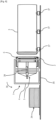
- FIG. 1 shows an insertion device 5 comprising fixing means in accordance with one aspect of the invention and gripping here a section of packing 2 for a gas/liquid separation column at the top of a stack 24 of sections of packing 2.
- the insertion device 5 is part of a system for the horizontal insertion of packing sections 2 within a shell with the aim of forming a column gas/liquid separation. Such an insertion system will be described in detail later.
- the insertion device 5 participates in the implementation of a process for inserting said packing sections for a gas/liquid separation column within the shroud.
- the insertion device 5 comprises a base 8 provided with attachment means 6 enabling the insertion device 5 to grip a section of packing 2, regardless of the diameter of said section of packing 2.
- the attachment means 6 are six in number.
- the base 8 comprises a main upright 9 and a plurality of peripheral uprights 10 parallel to the main upright 9.
- the main upright 9 extends mainly along a main axis 11 passing through the center or substantially through the center of the trim section 2 gripped.
- the peripheral uprights 10 are arranged in a circumferential and regular manner around the main upright 9. It is at the level of the peripheral uprights 10 that the attachment means 6 mentioned above are arranged.
- Base 8 comprises at least two peripheral uprights 10.
- base 8 comprises at least six peripheral uprights 10.
- Such a base 8 makes it possible to grip a section of packing 2 of a defined diameter.
- the base 8 can be able to deploy to cover a plurality of diameters of packing section 2.
- each peripheral upright 10 can be mechanically connected to the main upright 9 by two branches 12 forming a duo of branches 13.
- Each of the two branches 12 comprises a first end 14 connected to the main upright 9, and a second end 15 connected to the peripheral upright 10.
- the two branches 12 of the pair of branches 13 intersect with each other and are connected between them at their point of intersection, that is to say substantially at their center, by a pivot connection 16.
- the main upright 9 comprises two fixed rings 17, each of the fixed rings 17 being arranged at the level of each terminal portion of said main upright 9.
- the main upright 9 comprises a telescopic body 18 capable of modifying a main dimension of the main upright 9.
- the length of the main upright 9 can be adjusted manually or via a control member, not shown.
- the telescopic body 18 makes it possible to modify the length of the main upright 9 by deploying or retracting at least one of the end portions thereof.
- each branch 12 of the pair of branches 13 connecting the main upright 9 to one of the peripheral uprights 10 is more particularly linked to one of the fixed rings 17 arranged on the main upright 9.
- Each pair of branches 13 thus comprises a first branch 12a whose first end 14 is connected to a first fixed ring 17a, and a second branch 12b whose first end 14 is connected to a second fixed ring 17b.
- the second end 15 of the two branches 12 is itself fixed to the peripheral upright 10 and at least one of them can slide along the latter, for example using a slide 19 formed in the level of one of the faces of the peripheral upright 10.
- the distance between the fixed rings 17 and therefore the distance between the first ends 14 of each of the two branches 12 are also modified.
- the branches 12 being connected at a point forming a pivot connection 16, this point tends to approach or move away from the main upright 9 depending on the spacing or the approximation of one another of the first ends 14.
- the movement of the telescopic body 18 thus causes a modification of the inclination of the branches 12 of each of the pairs of branches 13 and thus modifies a radial distance between the main upright 9 and the peripheral uprights 10.
- the attachment means 6 can thus be moved apart so as to be able to engage around sections of packing 2 of different diameters.
- the base 8 as it has just been mentioned therefore makes it possible to adapt the insertion device 5 to a plurality of diameters of sections of packing 2 and ferrules.
- the locking means 20 can for example be associated with a plurality of deployable bars 21 extending between two adjacent peripheral uprights 10, such as this is illustrated on the figure 1 .
- the hooking means 6 can be adjusted to correctly grip the trim section 2, regardless of its diameter.
- the attachment means 6 Due to the gripping of the packing section 2 by the edge, associated with the fact that the packing sections 2 have a cylindrical shape with a circular or substantially circular section, the attachment means 6 have the shape of an arc of a circle, and this so that the assembly of the attachment means 6 intended to be in contact with the trim section 2 conforms to a radius of curvature of the latter. Gripping of the packing section 2 is thus facilitated and more stable. So that the gripping of the trim section 2 by the attachment means 6 is optimal, the curvature of the arc of a circle formed by the attachment means 6 is adjustable in order to adapt to all diameters of trim sections. 2.
- the latter After gripping of the packing section 2 by the attachment means 6, the latter can be controlled individually relative to each other in order to push on a specific point of the packing section 2 and locally deform this last.
- Such local deformation can be recommended when a shape differential exists between the packing section 2 and the shroud within which the packing section 2 is intended to be inserted.
- the local deformation thus makes it possible to slightly modify the shape of the packing section 2 so that the latter can subsequently be inserted into the ferrule more easily.
- At least two of the peripheral uprights 10 are provided with telescopic devices 22.
- the telescopic devices 22 can be arranged on a peripheral upright 10 also provided with a hooking means 6, the main thing being that all of these elements do not not mechanically interfere with each other.
- the telescopic devices 22 make it possible to operate a thrust of the packing section 2 once the latter has been put in place opposite the shell. This thrust is performed when the attachment means 6 have been ordered to release the packing section 2.
- the telescopic devices 22 deploy in order to push the packing section 2 to the end of the ferrule, regardless of the length of the latter. If one or more packing sections 2 have already been previously inserted into the shroud, the telescopic devices push the packing section 2 until the latter is in contact with the packing section 2 previously inserted.
- the telescopic devices 22 can be integrated into the base 8 previously described. On the figure 1 , the insertion device 5 being in the process of to grip a section of packing 2 on the stack 24, the telescopic devices 22 are therefore
- the insertion device 5 also comprises a plurality of fixing means 39.
- the latter each comprise a hook 28 intended to fix and hold the insertion device 5 against the ferrule during the insertion of the packing sections 2 within the ferrule.
- the insertion device 5 is in the process of gripping a section of lining 2.
- the fixing means 39 are therefore not used at this stage of the insertion process. Therefore, the hooks 28 have a retracted position so as not to interfere mechanically with the gripping of the trim sections 2 by the hooking means 6.
- the hooks 28 are therefore set back from the hooking means 6 with respect to the main axis 11, that is to say with the hooking means which are positioned at a distance from the free end of the peripheral uprights 10. This retracted position also allows the hooks 28 not to abut against the ground when the insertion device 5 grips the last trim section 2 of the stack 24 of trim sections 2.
- FIG. 2 represents the horizontal insertion system 1 of packing sections 2 as mentioned previously, during insertion of a packing section 2 within the shroud 3, with the aim of forming a gas/liquid separation column .
- separation columns are for example in a cylindrical shape with a circular or substantially circular section.
- the separation columns can have a main dimension of several tens of meters and a cylindrical section of several meters.
- the sections of packing 2 brought to be inserted within these separation columns can have a circular or substantially circular section with a diameter of the order of 2.5 m to 5 m.
- the system 1 for inserting sections of packing 2 makes it possible to operate the method of inserting said sections of packing 2 within the shroud 3, although the latter is in a horizontal position and therefore can lead to mechanical stress.
- the insertion system 1 After gripping of a trim section 2 by the insertion device 5, as illustrated in the figure 1 , the insertion system 1 then makes it possible to perform a rotation in order to arrange the section of packing 2 facing an inlet of the ferrule 3, to move as far as the inlet of the ferrule 3, then to push the section of packing 2 to the bottom of the shell 3 or against another section of packing 2 already inserted within the shell 3, ensuring the most fluid advance possible, that is to say with as few jolts as possible, of the packing section 2 within the ferrule 3.
- the insertion system 1 comprises a support structure 4 in the form of a gantry comprising two pillars 7 between which rests the insertion device 5.
- the support structure 4 can for example be mounted on rails in order to that the insertion system 1 can operate a linear movement between the stack of packing sections 2 and the ferrule 3.
- the insertion system 1 also comprises a first motor 25 allowing the insertion device 5 to perform a translation movement as a whole relative to the supporting structure 4.
- the insertion system 1 also comprises a second motor 26 allowing to actuate a system of gears 27 allowing to move the insertion device 5 as a whole so as to perform a rotation relative to the support structure 4. This rotation allows the insertion device 5 to pass from from a vertical position to a horizontal position, so as to be able to arrange the packing section 2 opposite the inlet of the shroud 3 as mentioned above.
- the telescopic devices 22 are deployed.
- the insertion device 5 comprises six peripheral uprights 10, three of which are provided with telescopic devices 22.
- the distribution of the telescopic devices 22 is carried out in a regular manner around the main axis 11.
- the insertion system 1 is structured so that the telescopic devices 22 can deploy in the horizontal direction, in order to perform the insertion step within the ferrule 3 arranged horizontally.
- the telescopic devices 22 are able to deploy parallel to the main axis 11 and to an axis of elongation of the peripheral uprights 10.
- the fixing means 39 are implemented so that the hooks 28, then in the retracted position as shown on the face 1 , are deployed.
- the hooks 28 make it possible to fix the insertion system 1 to the ferrule 3, for example by coming into engagement on a flange 29 extending circumferentially around the ferrule 3 at the level of the end of the ferrule 3 through which the packing sections 2 are inserted. More specifically, one end of each hook 28 forms a termination which is intended to come into contact, in the deployed position of this hook, with a face of the collar 29 which is oriented away from the insertion device 5.
- the hook 28 in contact with the flange 29 forms an axial stop to the relative movement of the ferrule with respect to the insertion device.
- the hooks 28 thus ensure a mechanical hold of the ferrule 3 facing the insertion device 5, including during the insertion of the packing section 2 within the ferrule 3.
- the presence of these hooks 28 makes it possible to carry out a sufficient counterweight to retain the ferrule 3 despite the forces exerted on it during the insertion of the packing sections 2.
- the fact that the insertion device 5 is equipped with such hooks 28 makes it possible to avoid providing for the presence of a bulky and heavy counterweight arranged at the rear of the shroud 3 to block the latter during the thrust force for the insertion of the packing section 2.
- the insertion device 5 comprises a thrust means 23 fixed to the end of each device telescopic 22, this pushing means 23 being intended to be in direct contact with the packing section 2 during insertion.
- the thrust means 23 mechanically distributes the forces exerted by each of the telescopic devices 22 by pressing on the entire periphery of the packing section 2, so as to avoid the localization of the forces only at the end of the telescopic devices 22.
- the means thrust 23 thus makes it possible to avoid damaging the section of lining 2 inserted due to a localized thrust force.
- the thrust means 23 is arranged in the vicinity of the peripheral uprights 10.
- the insertion device 5 can therefore comprise a holding member 32 connected to all of the telescopic devices 22 and arranged so as to be substantially at equal distance between the thrust means 23 and the inlet of the ferrule 3.
- holding member 32 has the function of maintaining the position of each of the telescopic devices 22 as well as the distance between each of them. The holding member 32 therefore contributes to the distribution of the forces exerted on the section of lining 2 inserted.
- the holding member 32 also ensures the stability of the telescopic devices 22, avoiding potential bending of the latter which may occur in the event of extension to a great length of the said telescopic devices 22.
- the holding member 32 has a triangular shape in order to hold three telescopic devices 22 evenly distributed around the main axis 11.
- the shape of the holding member 32 can however vary depending on the number of telescopic devices 22 included in the insertion device 5.
- the holding member 32 may comprise a set of rollers, each arranged in the extension of the branches of the holding member, beyond the telescopic devices, which are respectively in contact with the internal face of the peripheral wall of the shell.
- the aim is then to ensure continuous guidance of the retaining member within the ferrule during the deployment of the telescopic devices and the insertion of a section of packing.
- This continuous guidance by contact of at least one of the rollers against the ferrule, facilitates insertion despite the weight of the assembly formed by the telescopic arms and the thrust means 23 which could cause the assembly to come off axis.
- the thrust means may also comprise one or more rollers arranged on the periphery to be in contact with the internal face of the tubular wall of the shroud during insertion of the packing sections within the shroud.
- There picture 3 represents in detail the means of attachment 39 and makes it possible to illustrate the operation of said means of attachment 39.
- the latter in addition to comprising the hook 28 described above, also comprises a retractable cylinder 30 and a drive assembly 40 mechanically connecting the retractable jack 30 to hook 28.
- the retractable cylinder 30 may for example be a hydraulic or pneumatic cylinder whose translational movement drives that of the hook 28, via the drive assembly 40. To do this, the retractable cylinder 30 comprises a rod 45 constituting a movable part of the retractable cylinder 30 and capable of pushing or pulling the drive assembly 40.
- the drive assembly 40 comprises a connecting rod 41 and a crank 46.
- the connecting rod 41 is driven by the rod 45 of the retractable jack 30, which in turn drives the crank 46.
- the latter then drives the hook 28.
- the connecting rod 41 and the crank 46 make it possible to convert a linear movement 43 implemented by the retractable cylinder 30 into a pivoting movement 44 of the hook 28.
- each attachment means 6 is arranged on one of the peripheral uprights 10 so as to extend in the direction of the main axis 11 in order to be engaged on the edge of the trim section.
- Each hook 28 is therefore fixed to one of the peripheral uprights 10 so as to assume a retracted position facing a face of said peripheral upright 10 facing away from the main axis 11.
- the hook 28 comprises a termination 42.
- This has a tip extending projecting from the body of the hook 28 and which is intended to come into direct contact with the collar of the ferrule when the hook 28 is in the deployed position.
- the contact between the hook and the collar thus forms a point axial abutment of the insertion device on the ferrule, such that the ferrule is blocked axially, in the same direction as the direction of insertion of the sections in the ferrule.
- the hooks thus make it possible to hold the insertion system in position relative to the ferrule despite the high thrust force generated by the telescopic devices during insertion of the packing sections.
- FIG 4 also represents the fixing means 39, but this time with the hook 28 positioned so as to fix the insertion system to the collar 29 of the ferrule 3.
- the telescopic cylinder 30 retracts according to the linear movement 43, and the drive assembly 40 is also set in motion so that the connecting rod 41 drives the hook 28 in pivoting 44 so that said hook 28 closes on the ferrule 3 and that the termination 42 comes into contact with the flange 29.
- the termination 42 comes into contact with a face of the flange 29 which is opposite the insertion device, so that the termination 42 prevents the flange and therefore the ferrule from move away from the insertion device during the thrust force generated for the insertion of a section of packing.
- each hook 28 may comprise two ends 42 linked together by a spacer 47, in order to increase the number of points of contact between the hooks 28 and the collar 29.
- the insertion system is then ready to insert the section of packing 2 carried by the attachment means 6 within the ferrule 3.
- the figure 5 represents in particular a step of gripping a section of packing 2 on the vertical stack 24 of sections of packing 2.
- the insertion system 1 can move as a whole as far as the stack 24 of sections of packing , for example using rails 34 as mentioned above.
- the insertion device 5 is able to carry out as a whole a translational movement 35 with respect to the support structure 4, for example a translation along pillars 7 vertically, that is to say parallel to said pillars 7.
- This translation movement 35 can be ensured for example by the first motor 25 actuated remotely.
- This translational movement 35 is for example used so that the insertion device 5 reaches the top of the vertical stack 24 of packing sections 2 and overhangs the latter, as illustrated in the figure below. figure 5 .
- the translational movement 35 makes it possible to bring the insertion device 5 closer to the stack 24 of packing sections 2 in order to gripping the section of packing 2 at the top of said stack 24 via the hooking means 6.
- the insertion device 5 is again moved vertically in order to lift the section trim 2 gripped.
- the insertion device 5 comprises rotation means, here via the gear system illustrated in the figure 2 , ensuring at least a 90° or substantially 90° rotation 36 of the insertion device 5 with respect to the supporting structure 4.
- the second motor 26 can be carried by the supporting structure 4 and controlled so that the output shaft motor actuates the system of gears and therefore the rotation 36 of the insertion device 5 with respect to the supporting structure 4.
- This rotation device driven by the second motor 26 thus allows the insertion device 5 to switch between a first position called vertical, making it possible to grip the packing sections 2 on the stack 24 of packing sections 2 as illustrated in figure 5 , and a second so-called horizontal position in order to arrange the section of packing 2 gripped opposite the horizontal shell 3 as shown in the figure 6 .
- the supporting structure 4 can move while carrying the insertion device 5 in order to bring the section of packing 2 gripped closer to the ferrule 3 in order to insert it therein, for example thanks to the rails 34 such as mentioned previously.
- the latter can be arranged on supports 37.
- FIG. 7 illustrates the step of positioning the insertion device 5 at the entrance of the ferrule 3 as well as the step of pushing the packing section 2 within the ferrule 3.
- the vertical position of the insertion device 5 can possibly be adjusted thanks to the vertical translational movement along the pillars 7 of the supporting structure 4 so that the trim section 2 gripped is perfectly opposite the inlet of the ferrule 3.
- the fixing device 39 is implemented as illustrated in the figure 3 And 4 so that the hooks 28 come to close on the flange 29 of the ferrule 3 and can thus hold the insertion system 1 and more particularly the insertion device 5 opposite the entrance to the ferrule 3.
- the pushing step begins after the attachment means 6 release the packing section 2.
- the latter can for example rest on a retaining support 38 so that the packing section 2 remains positioned correctly facing the entrance of the shell.
- the telescopic devices 22 then deploy so that the thrust means 23 inserts the packing section 2 within the shroud 3, as described above.
- the telescopic devices 22 can retract, and the insertion system 1 can once again move to recover the next packing section 2. The insertion process then starts again from the gripping step described in figure 5 .
- the invention achieves the object it had set itself, and makes it possible to propose a device for inserting a section of packing into a horizontal shell comprising fastening means making it possible to maintain said insertion device against said ferrule.
- Variants not described here could be implemented without departing from the context of the invention, provided that, in accordance with the invention, they comprise an insertion device in accordance with the invention.
Landscapes
- Chemical & Material Sciences (AREA)
- Chemical Kinetics & Catalysis (AREA)
- Organic Chemistry (AREA)
- Engineering & Computer Science (AREA)
- Analytical Chemistry (AREA)
- General Chemical & Material Sciences (AREA)
- Oil, Petroleum & Natural Gas (AREA)
- Physics & Mathematics (AREA)
- Thermal Sciences (AREA)
- Mechanical Engineering (AREA)
- Automatic Assembly (AREA)
- Joints With Pressure Members (AREA)
Abstract
Description
- La présente invention se rapporte au domaine des colonnes de séparation gaz/liquide et à leur assemblage et elle concerne plus particulièrement un dispositif d'insertion de tronçons de garnissage dans une virole afin de former ces dites colonnes de séparation gaz/liquide.
- Les colonnes de séparation gaz/liquide sont connues depuis de nombreuses années et permettent par exemple de réaliser une séparation de différents éléments chimiques entrant dans la composition d'un fluide homogène, par exemple par distillation ou par absorption.
- La fabrication d'une colonne de séparation gaz/liquide comprend notamment une étape d'insertion d'une pluralité de tronçons de garnissage pour une colonne de séparation gaz/liquide au sein d'une virole. Les tronçons de garnissages sont notamment utilisés dans les colonnes pour assurer l'échange de matière et de chaleur entre un gaz montant et un liquide descendant. Ces tronçons de garnissage, qui sont notamment constitués par une superposition de plusieurs bandes ondulées, sont souvent appelés "packs". Les tronçons de garnissage sont classiquement empilés les uns sur les autres, le cas échéant avec des séparateurs interposés, afin de participer à la séparation des composants du fluide sur la dimension axiale de la colonne.
-
JP H01 242102 - Il est connu de procéder à l'insertion des tronçons de garnissage au sein d'une virole maintenue verticale, la force de gravité facilitant grandement la progression du tronçon de garnissage inséré au sein de la virole. Un tel procédé peut toutefois s'avérer contraignant lorsque les colonnes de séparation gaz/liquide à assembler présentent un diamètre important et une dimension axiale nécessitant la mise en oeuvre de viroles de grande longueur, de l'ordre de plusieurs dizaines de mètres. En effet, de tels procédés avec une insertion verticale des tronçons de garnissage nécessitent alors un outillage apte à soulever les tronçons de garnissage sur une grande distance afin de les mettre en regard de l'extrémité de la virole ainsi qu'un site de production présentant une hauteur de plafond supérieure à la longueur de la virole.
- Il est donc souhaité, pour les viroles de longueur élevée, de prévoir un procédé d'assemblage dans lequel l'insertion des tronçons de garnissage est effectuée avec la virole agencée à l'horizontale. Une telle position génère plusieurs contraintes, notamment celle de devoir agencer un contrepoids au contact de l'extrémité de la virole opposée à celle où sont insérés les tronçons de garnissage afin de retenir la virole lors de l'insertion. L'insertion des tronçons de garnissage nécessitant des forces de poussée très intenses, le contrepoids utilisé doit être suffisamment imposant pour résister à de telles forces de poussée.
- La présente invention permet de se passer d'un tel contrepoids en proposant un dispositif d'insertion d'au moins un tronçon de garnissage au sein d'une virole cylindrique, comprenant une base pourvue de moyens d'accroche configurés pour agripper un tronçon de garnissage et disposés régulièrement autour d'un axe principal, caractérisé en ce que le dispositif d'insertion comprend au moins deux moyens de fixation solidaires de la base, lesdits moyens de fixation étant configurés pour fixer le dispositif d'insertion à la virole.
- Grâce aux moyens de fixation, le dispositif d'insertion est maintenu contre la virole, y compris lors de l'insertion des tronçons de garnissage. L'insertion des tronçons de garnissage peut par exemple être effectuée par des dispositifs télescopiques se déployant afin d'opérer une poussée du tronçon de garnissage. De tels dispositifs peuvent présenter une force de poussée importante au point d'entraîner un déplacement non souhaité de la virole. Les moyens de fixation pallient cette éventualité en retenant la virole et en opérant ainsi une force opposée à la force des dispositifs assurant l'insertion des tronçons de garnissage dans la virole.
- Le dispositif d'insertion permet le remplissage d'une virole par une pluralité de tronçons de garnissage pour une colonne de séparation gaz/liquide afin de former une colonne de séparation gaz/liquide. La base du dispositif d'insertion, plus particulièrement les moyens d'accroche de celle-ci, sont aptes à agripper un tronçon de garnissage par les côtés de celui-ci. Les tronçons de garnissage présentant une forme circulaire pouvant aller jusqu'à 5m de diamètre, la base doit donc être dimensionnée de sorte à ce que les moyens d'accroche puissent agripper un tel tronçon de garnissage par les côtés. L'axe principal autour duquel sont disposés les moyens d'accroche peut par exemple passer par le centre du tronçon de garnissage et/ou être parallèle ou confondu avec l'axe de révolution de la virole. Une fois le tronçon de garnissage agrippé, ce dernier est positionné au niveau de l'entrée de la virole, et le maintien du dispositif d'insertion contre la virole, par l'intermédiaire des moyens de fixation, peut être mis en oeuvre. Ceci étant fait, le tronçon de garnissage peut être inséré au sein de la virole, et ce sans disposer un encombrant contrepoids contre l'extrémité opposée de la virole pour compenser les forces de poussée lors de l'insertion.
- Selon une caractéristique de l'invention, les moyens de fixation sont agencés de manière régulière autour de l'axe principal. La répartition régulière des moyens de fixation évite une inégalité des compensations des forces de poussée exercées sur le tronçon de garnissage lors de l'insertion de celui-ci au sein de la virole. Une répartition irrégulière des moyens de fixation, ou la présence d'un unique moyen de fixation risque de créer un recul non homogène de la virole lors de l'insertion du tronçon de garnissage, particulièrement au niveau d'une ou plusieurs zones éloignées du ou des moyens de fixation, et donc de créer un désaxage entre la virole et les tronçons de garnissage qui doivent être insérés à l'intérieur de la virole.
- Selon une caractéristique de l'invention, au moins un moyen de fixation et un moyen d'accroche sont agencés sur un même montant périphérique de la base. La base peut ainsi comprendre une pluralité de montants périphériques, tous agencés et répartis régulièrement autour de l'axe principal. Un montant périphérique peut ainsi être porteur d'un moyen d'accroche seul, d'un moyen de fixation seul, ou bien des deux à la fois, l'essentiel étant que le moyen d'accroche et le moyen de fixation ne créent pas d'interférence mécanique l'un envers l'autre pouvant nuire au bon déroulement de la fonction de l'un et/ou de l'autre.
- Selon une caractéristique de l'invention, les moyens de fixation comprennent chacun un vérin rétractable, un crochet, et un ensemble d'entraînement reliant mécaniquement le vérin rétractable au crochet. Le crochet correspond à la partie du moyen de fixation venant se refermer sur la virole afin de maintenir le dispositif d'insertion en regard de celle-ci. Le vérin rétractable permet de contrôler une position du crochet via le dispositif d'entraînement. A ce titre, le vérin rétractable peut par exemple être un vérin hydraulique ou pneumatique.
- Selon une caractéristique de l'invention, l'ensemble d'entraînement comprend au moins une bielle et une manivelle configurées pour entraîner un pivotement du crochet en fonction d'un mouvement linéaire du vérin rétractable. Le vérin rétractable génère le mouvement linéaire en se déployant ou en se rétractant. Ce mouvement entraîne l'ensemble d'entraînement. La bielle étant mise en mouvement, celle-ci entraîne alors la manivelle qui à son tour entraîne le mouvement du crochet. C'est grâce à la bielle et à la manivelle que le mouvement linéaire du vérin rétractable est converti en un mouvement de pivotement du crochet.
- Selon une caractéristique de l'invention, les crochets sont aptes à pivoter entre une position escamotée et une position déployée. Ces deux positions sont dépendantes de la position du vérin rétractable. A titre d'exemple, lorsque ce dernier est entièrement déployé, le crochet est en position escamotée et lorsque le vérin rétractable est entièrement rétracté, le crochet est en position déployée. Le vérin rétractable peut par exemple être actionné à distance afin de déployer ou d'escamoter le crochet en fonction du besoin. Un crochet en position déployée est en position pour se fixer à la virole et maintenir le dispositif d'insertion en regard de celle-ci. La position déployée est donc mise en oeuvre lors du positionnement du dispositif d'insertion en regard de la virole, une fois un tronçon de garnissage en regard de la virole et prêt à être inséré, et est maintenue lors de l'insertion du tronçon de garnissage au sein de la virole. Selon une caractéristique de l'invention, les crochets en position escamotée sont en retrait des moyens d'accroches par rapport à l'axe principal. La position escamotée est mise en oeuvre pour éviter de potentielles interférences mécaniques entre les crochets en position déployée et tout autre élément du dispositif d'insertion. Cette position escamotée est notamment utile lorsque le dispositif d'insertion est mis en oeuvre pour agripper un tronçon de garnissage à l'aide des moyens d'accroche. Les crochets sont alors pivotés pour être en retrait desdits moyens d'accroche par rapport à l'axe principal, avec les crochets escamotés à distance de l'extrémité libre des montants périphériques, afin que les crochets ne butent pas contre un tronçon de garnissage ou contre un support où sont disposés les tronçons de garnissage.
- Selon une caractéristique de l'invention, le pivotement des crochets se fait au niveau d'une face du montant périphérique opposée aux moyens d'accroche. Une telle configuration permet aux crochets de ne pas buter contre les moyens d'accroche lors de leur pivotement.
- Selon une caractéristique de l'invention, chaque crochet comprend une terminaison configurée pour être en contact direct avec une collerette de la virole. La terminaison vient ainsi former une butée axiale contre la virole, c'est-à-dire parallèle à l'axe principal, afin de maintenir correctement le dispositif d'insertion contre la virole. Afin que la prise des crochets soit optimale, la virole peut comprendre une collerette s'étendant circonférentiellement autour de la virole et contre laquelle la terminaison de chaque crochet vient buter lorsque les crochets sont en position déployée.
- L'invention couvre également un système d'insertion d'au moins un tronçon de garnissage au sein d'une virole cylindrique, comprenant une structure porteuse et un dispositif d'insertion tel que décrit précédemment, le dispositif d'insertion étant porté par la structure porteuse de sorte à ce que les moyens de fixation soient aptes à fixer le dispositif d'insertion à la virole.
- La structure porteuse se présente sous la forme d'un portique apte à se déplacer selon au moins une direction tout en portant le dispositif d'insertion agrippant un tronçon de garnissage. Pour opérer un tel déplacement, la structure porteuse peut par exemple être agencé sur des rails afin que le déplacement se fasse selon la direction la plus précise possible.
- Tel que cela a été évoqué, l'objectif du système d'insertion selon l'invention est d'insérer des tronçons de garnissage pour une colonne de séparation gaz/liquide au sein d'une virole agencée horizontalement, et ce sans besoin d'agencer un contrepoids à l'opposé de l'entrée de la virole. Les moyens de fixation sont donc configurés pour maintenir ledit système d'insertion contre la virole malgré les forces de poussée exercées sur le tronçon de garnissage lors de l'opération d'insertion de celui-ci.
- Selon une caractéristique de l'invention, le dispositif d'insertion est apte à effectuer dans son ensemble un mouvement de translation de manière relative à la structure porteuse. Indépendamment de la structure porteuse, le dispositif d'insertion peut se déplacer par exemple de manière verticale. Ce déplacement vertical est utile par exemple pour positionner le dispositif d'insertion à l'aplomb d'une pile de tronçons de garnissage, puis pour le descendre dans le but d'agripper le tronçon de garnissage disposé au sommet de la pile. Le déplacement vertical du dispositif d'insertion par rapport à la structure porteuse est également utile dans le but d'ajuster la position du tronçon de garnissage agrippé afin de positionner correctement celui-ci à l'entrée de la virole et ainsi de favoriser la poussée du tronçon de garnissage au sein de la virole. Le déplacement relatif du dispositif d'insertion par rapport à la structure porteuse peut par exemple se faire à l'aide d'un moteur embarqué sur la structure porteuse et configuré pour déplacer un élément porteur du dispositif d'insertion le long de la structure porteuse.
- Selon une caractéristique de l'invention, le dispositif d'insertion est apte à effectuer dans son ensemble une rotation de manière relative à la structure porteuse. La rotation permet notamment de basculer le dispositif d'insertion, avec une structure porteuse qui reste fixe, entre une position où le dispositif d'insertion est agencé de manière verticale dans le but d'agripper un tronçon de garnissage sur une pile verticale de tronçons de garnissage, et une position où le dispositif d'insertion est agencé de manière horizontale dans le but de procéder à l'insertion du tronçon de garnissage agrippé au sein de la virole. Les éléments de rotation doivent donc être configurés pour permettre une rotation du dispositif d'insertion d'environ 90°, afin que le dispositif d'insertion puisse basculer entre les positions verticales et horizontales évoquées précédemment. La rotation relative du dispositif d'insertion par rapport à la structure porteuse peut par exemple se faire à l'aide d'un moteur apte à piloter un système à engrenages entraînant la rotation du dispositif d'insertion, ou bien encore via un système à chaîne ou un système hydraulique.
- L'invention couvre également un procédé d'insertion d'au moins un tronçon de garnissage pour une colonne de séparation gaz/liquide au sein d'une virole cylindrique mis en oeuvre par un système d'insertion tel que décrit précédemment, comprenant :
- une étape d'agrippement d'un tronçon de garnissage par les moyens d'accroche du dispositif d'insertion,
- une étape de rotation dans son ensemble du dispositif d'insertion par rapport à la structure porteuse,
- une étape de déplacement du système d'insertion jusqu'à la virole grâce à la structure porteuse,
- une étape de positionnement du tronçon de garnissage au niveau d'une entrée de la virole,
- une étape de fixation du dispositif d'insertion à la virole à l'aide des moyens de fixation,
- une étape de poussée du tronçon de garnissage au sein de la virole.
- Les étapes du procédé se font à l'aide des différents éléments évoqués précédemment du système d'insertion. Ainsi, l'étape d'agrippement se fait à l'aide des moyens d'accroche du dispositif d'insertion et des moyens de mise en translation du dispositif d'insertion par rapport à la structure porteuse, l'étape de rotation à l'aide des éléments de rotation embarqués sur la structure porteuse, l'étape de déplacement via la structure porteuse, l'étape de positionnement à l'aide des moyens de mise en translation du dispositif d'insertion par rapport à la structure porteuse, l'étape de fixation grâce aux moyens de fixation et l'étape de poussée à l'aide des dispositifs télescopiques. Il convient de noter qu'il s'agit ici d'une liste d'étapes non exhaustive pour le bon déroulement du procédé d'insertion de tronçons de garnissage au sein de la virole selon l'invention. A titre d'exemple non limitatif, on pourra prévoir dans le procédé selon l'invention une étape de contrôle du bon positionnement du tronçon de garnissage une fois inséré dans la virole. Cette étape additionnelle, venant ici à la suite de l'étape de poussée, consiste alors en une vérification et un enregistrement de la bonne position du tronçon de garnissage qui vient d'être inséré, à l'aide d'un appareil de mesure précis au millimètre.
- D'autres caractéristiques et avantages de l'invention apparaîtront encore au travers de la description qui suit d'une part, et de plusieurs exemples de réalisation donnés à titre indicatif et non limitatif en référence aux dessins schématiques annexés d'autre part, sur lesquels :
- [
Fig. 1 ] représente une vue de côté d'un dispositif d'insertion selon l'invention et d'une pile de tronçons de garnissage pour une colonne de séparation gaz/liquide aptes à être saisi par le dispositif d'insertion, - [
Fig. 2 ] est une vue générale d'un système d'insertion d'un tronçon de garnissage pour une colonne de séparation gaz/liquide dans une virole selon l'invention, - [
Fig. 3 ] est une vue détaillée d'un moyen de fixation du dispositif d'insertion, - [
Fig. 4 ] est une vue détaillée du moyen de fixation accroché à la virole, - [
Fig. 5 ] représente une étape d'agrippement du tronçon de garnissage pour une colonne de séparation gaz/liquide d'un procédé d'insertion de tronçons de garnissage, - [
Fig. 6 ] représente une étape de rotation du dispositif d'insertion et de déplacement du système d'insertion du procédé d'insertion de tronçons de garnissage pour une colonne de séparation gaz/liquide, - [
Fig. 7 ] représente une étape d'insertion du tronçon de garnissage du procédé d'insertion de tronçons de garnissage pour une colonne de séparation gaz/liquide. - La
figure 1 représente un dispositif d'insertion 5 comportant des moyens de fixation conformes à un aspect de l'invention et agrippant ici un tronçon de garnissage 2 pour une colonne de séparation gaz/liquide au sommet d'une pile 24 de tronçons de garnissage 2. Le dispositif d'insertion 5 fait partie d'un système d'insertion horizontale de tronçons de garnissage 2 au sein d'une virole dans le but de former une colonne de séparation gaz/liquide. Un tel système d'insertion sera décrit en détails par la suite. Le dispositif d'insertion 5 participe à la mise en oeuvre d'un procédé d'insertion desdits tronçons de garnissage pour une colonne de séparation gaz/liquide au sein de la virole. Le dispositif d'insertion 5 comprend une base 8 pourvue de moyens d'accroche 6 permettant au dispositif d'insertion 5 d'agripper un tronçon de garnissage 2, et ce peu importe le diamètre dudit tronçon de garnissage 2. Sur lafigure 1 , les moyens d'accroche 6 sont au nombre de six. - La base 8 comprend un montant principal 9 et une pluralité de montants périphériques 10 parallèles au montant principal 9. Le montant principal 9 s'étend principalement selon un axe principal 11 passant par le centre ou sensiblement par le centre du tronçon de garnissage 2 agrippé. Les montants périphériques 10 sont agencés de manière circonférentielle et régulière autour du montant principal 9. C'est au niveau des montants périphériques 10 que sont agencés les moyens d'accroche 6 évoqués précédemment. La base 8 comprend au moins deux montants périphériques 10. D'une manière avantageuse, la base 8 comprend au moins six montants périphériques 10. Une telle base 8 permet d'agripper un tronçon de garnissage 2 d'un diamètre défini. D'une manière alternative, la base 8 peut être apte à se déployer pour couvrir une pluralité de diamètres de tronçon de garnissage 2. Pour ce faire, chaque montant périphérique 10 peut être mécaniquement relié au montant principal 9 par deux branches 12 formant un duo de branches 13. Chacune des deux branches 12 comprend une première extrémité 14 liée au montant principal 9, et une deuxième extrémité 15 liée au montant périphérique 10. De plus, les deux branches 12 du duo de branches 13 sont sécantes entre elles et sont liées entre elles au niveau de leur point d'intersection, c'est-à-dire sensiblement en leur centre, par une liaison pivot 16. Le montant principal 9 comprend deux bagues fixes 17, chacune des bagues fixes 17 étant agencée au niveau de chaque portion terminale dudit montant principal 9. Le montant principal 9 comprend un corps télescopique 18 apte à modifier une dimension principale du montant principal 9. Ainsi, en modifiant la longueur du montant principal 9, il est possible d'augmenter ou de réduire la distance entre les deux bagues fixes 17. La longueur du montant principal 9 peut être réglée de manière manuelle ou via un organe de contrôle non représenté. Le corps télescopique 18 permet de modifier la longueur du montant principal 9 en déployant ou rétractant au moins l'une des portions terminales de celui-ci.
- La première extrémité 14 de chaque branche 12 du duo de branches 13 reliant le montant principal 9 à l'un des montants périphériques 10 est plus particulièrement liée à l'une des bagues fixes 17 agencées sur le montant principal 9. Chaque duo de branches 13 comprend ainsi une première branche 12a dont la première extrémité 14 est liée à une première bague fixe 17a, et une deuxième branche 12b dont la première extrémité 14 est liée à une deuxième bague fixe 17b. La deuxième extrémité 15 des deux branches 12 est quant à elle fixée sur le montant périphérique 10 et au moins l'une d'entre elles peut coulisser le long de celui-ci, par exemple à l'aide d'une glissière 19 formée au niveau de l'une des faces du montant périphérique 10.
- Ainsi, lorsque la longueur du montant principal 9 est modifiée grâce au corps télescopique 18, la distance entre les bagues fixes 17 et donc la distance entre les premières extrémités 14 de chacune des deux branches 12 sont également modifiées. Les branches 12 étant reliées en un point formant liaison pivot 16, ce point tend à se rapprocher ou s'éloigner du montant principal 9 en fonction de l'écartement ou du rapprochement l'une de l'autre des premières extrémités 14. Le mouvement du corps télescopique 18 entraîne de la sorte une modification de l'inclinaison des branches 12 de chacun des duos de branches 13 et modifie ainsi une distance radiale entre le montant principal 9 et les montants périphériques 10.
- Les moyens d'accroche 6 peuvent ainsi être écartés pour pouvoir être en prise autour de tronçons de garnissage 2 de différents diamètres. Plus la longueur du montant principal 9 est élevée, plus les bagues fixes 17 sont éloignées l'une par rapport à l'autre, et plus les montants périphériques 10 sont proches du montant principal 9, adaptant le dispositif d'insertion 5 à un petit diamètre de tronçon de garnissage 2. A l'inverse, plus la longueur du montant principal 9 est faible, plus les bagues fixes 17 sont rapprochées l'une par rapport à l'autre, et plus les montants périphériques 10 sont éloignés du montant principal 9, adaptant le dispositif d'insertion 5 à un grand diamètre de tronçon de garnissage 2. La base 8 telle qu'elle vient d'être évoquée permet donc d'adapter le dispositif d'insertion 5 à une pluralité de diamètres de tronçons de garnissage 2 et de viroles.
- Une fois la distance radiale souhaitée établie, celle-ci peut être figée par un moyen de verrouillage 20. Le moyen de verrouillage 20 peut par exemple être associé à une pluralité de barres déployables 21 s'étendant entre deux montants périphériques 10 adjacents, tel que cela est illustré sur la
figure 1 . - Avec une base 8 apte à se déployer tel que décrit précédemment, les moyens d'accroche 6 peuvent être réglés pour correctement saisir le tronçon de garnissage 2, et ce peu importe le diamètre de celui-ci.
- Du fait de la prise du tronçon de garnissage 2 par la tranche, associé au fait que les tronçons de garnissage 2 présentent une forme cylindrique à section circulaire ou sensiblement circulaire, les moyens d'accroche 6 présentent une forme d'arc de cercle, et ce afin que l'ensemble du moyen d'accroche 6 destiné à être au contact du tronçon de garnissage 2 épouse un rayon de courbure de celui-ci. L'agrippement du tronçon de garnissage 2 est ainsi facilité et plus stable. Afin que l'agrippement du tronçon de garnissage 2 par les moyens d'accroche 6 soit optimal, la courbure de l'arc de cercle formé par les moyens d'accroche 6 est réglable afin de s'adapter à tous diamètres de tronçons de garnissage 2.
- Après agrippement du tronçon de garnissage 2 par les moyens d'accroche 6, ces derniers peuvent être pilotés de manière individuelle l'un par rapport à l'autre dans le but de pousser sur un point précis du tronçon de garnissage 2 et déformer localement ce dernier. Une telle déformation locale peut être préconisée lorsqu'un différentiel de forme existe entre le tronçon de garnissage 2 et la virole au sein de laquelle le tronçon de garnissage 2 est destiné à être inséré. La déformation locale permet ainsi de modifier légèrement la forme du tronçon de garnissage 2 afin que celui-ci puisse par la suite être inséré dans la virole de manière plus aisée.
- Au moins deux des montants périphériques 10 sont pourvus de dispositifs télescopiques 22. Les dispositifs télescopiques 22 peuvent être agencés sur un montant périphérique 10 également pourvu d'un moyen d'accroche 6, l'essentiel étant que l'ensemble de ces éléments n'interfèrent pas mécaniquement les uns par rapport aux autres. Les dispositifs télescopiques 22 permettent d'opérer une poussée du tronçon de garnissage 2 une fois celui-ci mis en place en regard de la virole. Cette poussée est effectuée dès lors que les moyens d'accroche 6 ont été commandés pour lâcher le tronçon de garnissage 2. Les dispositifs télescopiques 22 se déploient afin de pousser le tronçon de garnissage 2 jusqu'au bout de la virole, et ce peu importe la longueur de cette dernière. Si un ou plusieurs tronçons de garnissage 2 ont déjà été précédemment insérés dans la virole, les dispositifs télescopiques poussent le tronçon de garnissage 2 jusqu'à ce que ce dernier soit au contact du tronçon de garnissage 2 précédemment inséré. Les dispositifs télescopiques 22 peuvent être intégrés à la base 8 précédemment décrite. Sur la
figure 1 , le dispositif d'insertion 5 étant en train d'agripper un tronçon de garnissage 2 sur la pile 24, les dispositifs télescopiques 22 sont donc repliés. - Le dispositif d'insertion 5 comprend également une pluralité de moyens de fixation 39. Ces derniers comprennent chacun un crochet 28 destiné à fixer et maintenir le dispositif d'insertion 5 contre la virole lors de l'insertion des tronçons de garnissage 2 au sein de la virole.
- Sur la
figure 1 , le dispositif d'insertion 5 est en cours d'agrippement d'un tronçon de garnissage 2. Les moyens de fixation 39 ne sont donc pas utilisés à ce stade du procédé d'insertion. De ce fait, les crochets 28 présentent une position escamotée afin de ne pas interférer mécaniquement avec l'agrippement des tronçons de garnissage 2 par les moyens d'accroche 6. Les crochets 28 sont donc en retrait des moyens d'accroche 6 par rapport à l'axe principal 11, c'est-à-dire avec les moyens d'accroche qui sont positionnés à distance de l'extrémité libre des montants périphériques 10. Cette position escamotée permet également aux crochets 28 de ne pas faire butée contre le sol lorsque le dispositif d'insertion 5 vient agripper le dernier tronçon de garnissage 2 de la pile 24 de tronçons de garnissage 2. - La
figure 2 représente le système d'insertion 1 horizontale de tronçons de garnissage 2 tel qu'évoqué précédemment, en cours d'insertion d'un tronçon de garnissage 2 au sein de la virole 3, dans le but de former une colonne de séparation gaz/liquide. De telles colonnes de séparation se présentent par exemple sous une forme cylindrique à section circulaire ou sensiblement circulaire. Les colonnes de séparation peuvent présenter une dimension principale de plusieurs dizaines de mètres et une section cylindrique de plusieurs mètres. Les tronçons de garnissage 2 amenés à être insérés au sein de ces colonnes de séparation peuvent présenter une section circulaire ou sensiblement circulaire d'un diamètre de l'ordre de 2,5m à 5m. - Pour des raisons d'encombrement mécanique en termes de hauteur rendant impossible l'opération d'insertion lorsque la virole 3 est agencée verticalement, ladite opération est ici effectuée avec la virole 3 en position horizontale, l'insertion des tronçons de garnissage 2 se faisant également selon une direction horizontale.
- Le système d'insertion 1 de tronçons de garnissage 2 selon l'invention permet d'opérer le procédé d'insertion desdits tronçons de garnissage 2 au sein de la virole 3, bien que celle-ci soit en position horizontale et de ce fait puisse entraîner des contraintes mécaniques.
- Après l'agrippement d'un tronçon de garnissage 2 par le dispositif d'insertion 5, tel que cela est illustré sur la
figure 1 , le système d'insertion 1 permet par la suite d'effectuer une rotation afin d'agencer le tronçon de garnissage 2 en regard d'une entrée de la virole 3, de se déplacer jusqu'à l'entrée de la virole 3, puis de pousser le tronçon de garnissage 2 jusqu'au fond de la virole 3 ou contre un autre tronçon de garnissage 2 déjà inséré au sein de la virole 3, en assurant une avancée la plus fluide possible, c'est-à-dire avec le moins d'à-coups possible, du tronçon de garnissage 2 au sein de la virole 3. - Pour ce faire, le système d'insertion 1 comprend une structure porteuse 4 se présentant sous la forme d'un portique comprenant deux piliers 7 entre lesquels repose le dispositif d'insertion 5. La structure porteuse 4 peut par exemple être montée sur rails afin que le système d'insertion 1 puisse opérer un déplacement linéaire entre la pile de tronçons de garnissage 2 et la virole 3.
- Le système d'insertion 1 comprend par ailleurs un premier moteur 25 permettant au dispositif d'insertion 5 d'effectuer dans son ensemble un mouvement de translation par rapport à la structure porteuse 4. Le système d'insertion 1 comprend également un deuxième moteur 26 permettant d'actionner un système d'engrenages 27 permettant de déplacer le dispositif d'insertion 5 dans son ensemble de sorte à effectuer une rotation de manière relative à la structure porteuse 4. Cette rotation permet de faire passer le dispositif d'insertion 5 d'une position verticale à une position horizontale, de manière à pouvoir agencer le tronçon de garnissage 2 en regard de l'entrée de la virole 3 tel que mentionné précédemment.
- Sur la
figure 2 , les dispositifs télescopiques 22 sont déployés. Le dispositif d'insertion 5 comprend six montants périphériques 10 dont trois d'entre eux sont pourvus de dispositifs télescopiques 22. La répartition des dispositifs télescopiques 22 est effectuée de manière régulière autour de l'axe principal 11. - Le système d'insertion 1 est structuré de sorte à ce que les dispositifs télescopiques 22 puissent se déployer selon la direction horizontale, et ce afin d'opérer l'étape d'insertion au sein de la virole 3 agencée à l'horizontale. Autrement dit, les dispositifs télescopiques 22 sont aptes à se déployer de manière parallèle à l'axe principal 11 et à un axe d'allongement des montants périphériques 10.
- Lorsque le dispositif d'insertion 5 est disposé à proximité de la virole 3 dans le but d'y insérer par la suite un tronçon de garnissage 2, les moyens de fixation 39 sont mis en oeuvre afin que les crochets 28, alors en position escamotée tel qu'illustré sur la
figure 1 , soient déployés. Dans leur position déployée, les crochets 28 permettent de fixer le système d'insertion 1 à la virole 3, par exemple en venant en prise sur une collerette 29 s'étendant de manière circonférentielle autour de la virole 3 au niveau de l'extrémité de la virole 3 par laquelle les tronçons de garnissage 2 sont insérés. Plus précisément, une extrémité de chaque crochet 28 forme une terminaison qui est destinée à venir en contact, dans la position déployée de ce crochet, avec une face de la collerette 29 qui est orientée à l'opposé du dispositif d'insertion 5. Une fois en position déployée, le crochet 28 au contact de la collerette 29 forme une butée axiale au déplacement relatif de la virole par rapport au dispositif d'insertion. Les crochets 28 assurent ainsi un maintien mécanique de la virole 3 en regard du dispositif d'insertion 5, y compris pendant l'insertion du tronçon de garnissage 2 au sein de la virole 3. La présence de ces crochets 28 permet d'effectuer un contrepoids suffisant pour retenir la virole 3 malgré les forces exercées sur celle-ci lors de l'insertion des tronçons de garnissage 2. Le fait que le dispositif d'insertion 5 soit équipé de tels crochets 28 permet d'éviter de prévoir la présence d'un contrepoids encombrant et lourd disposé à l'arrière de la virole 3 pour bloquer celle-ci lors de l'effort de poussée pour l'insertion du tronçon de garnissage 2. - Afin que l'insertion du tronçon de garnissage 2 au sein de la virole soit effectuée de manière uniforme, avec le minimum d'à-coups, le dispositif d'insertion 5 comprend un moyen de poussée 23 fixé à l'extrémité de chaque dispositif télescopique 22, ce moyen de poussé 23 étant destiné à être en contact direct avec le tronçon de garnissage 2 au cours de l'insertion. Le moyen de poussée 23 répartit mécaniquement les forces exercées par chacun des dispositifs télescopiques 22 en appuyant sur tout le pourtour du tronçon de garnissage 2, de manière à éviter la localisation des forces uniquement au niveau de l'extrémité des dispositifs télescopiques 22. Le moyen de poussée 23 permet ainsi d'éviter d'endommager le tronçon de garnissage 2 inséré à cause d'une force de poussée localisée. Lorsque les dispositifs télescopiques 22 sont repliés, le moyen de poussée 23 est disposé au voisinage des montants périphériques 10. Dans le cas où la base 8 est configurée pour se déployer radialement et s'adapter à différents diamètres de tronçon de garnissage 2, plusieurs moyens de poussée 23 de dimensions différentes sont conçus et l'installation du moyen de poussée 23 adéquat est effectuée après la détermination de la distance radiale entre le montant principal et les montants périphériques 10.
- Lorsque les dispositifs télescopiques 22 se déploient pour pousser le tronçon de garnissage 2 au sein d'une virole 3 présentant une longueur importante, par exemple plusieurs dizaines de mètres, les dispositifs télescopiques 22 se déploient jusqu'à atteindre une longueur conséquente pouvant nuire à leur stabilité. Le dispositif d'insertion 5 peut donc comprendre un organe de maintien 32 relié à l'ensemble des dispositifs télescopiques 22 et agencé de sorte à être sensiblement à égale distance entre le moyen de poussée 23 et l'entrée de la virole 3. L'organe de maintien 32 a pour fonction de maintenir la position de chacun des dispositifs télescopiques 22 ainsi que la distance entre chacun d'entre eux. L'organe de maintien 32 participe donc à la répartition des forces exercées sur le tronçon de garnissage 2 inséré. L'organe de maintien 32 assure également la stabilité des dispositifs télescopiques 22, en évitant de potentielles flexions de ces derniers pouvant survenir en cas d'extension à une longueur élevée desdits dispositifs télescopiques 22. Tel que cela est illustré en
figure 2 , l'organe de maintien 32 présente une forme triangulaire afin de maintenir trois dispositifs télescopiques 22 équitablement répartis autour de l'axe principal 11. La forme de l'organe de maintien 32 peut toutefois varier en fonction du nombre de dispositifs télescopiques 22 inclus dans le dispositif d'insertion 5. Dans une variante non représentée, l'organe de maintien 32 peut comporter un jeu de roulettes, disposées chacune dans le prolongement des branches de l'organe de maintien, au-delà des dispositifs télescopiques, qui sont respectivement au contact de la face interne de la paroi périphérique de la virole. On vise alors à assurer un guidage continu de l'organe de maintien au sein de la virole lors du déploiement des dispositifs télescopiques et l'insertion d'un tronçon de garnissage. Ce guidage continu, par contact d'au moins une des roulettes contre la virole, permet de faciliter l'insertion malgré le poids de l'ensemble formé par les bras télescopiques et le moyen de poussée 23 qui pourrait amener l'ensemble à se désaxer. De manière alternative ou complémentaire, le moyen de poussée peut également comporter une ou plusieurs roulettes agencées en périphérie pour être au contact de la face interne de la paroi tubulaire de la virole lors de l'insertion des tronçons de garnissage au sein de la virole. Lafigure 3 représente en détails le moyen de fixation 39 et permet d'illustrer le fonctionnement dudit moyen de fixation 39. Ce dernier, en plus de comprendre le crochet 28 décrit précédemment, comprend également un vérin rétractable 30 et un ensemble d'entraînement 40 reliant mécaniquement le vérin rétractable 30 au crochet 28. - Le vérin rétractable 30 peut par exemple être un vérin hydraulique ou pneumatique dont le mouvement en translation entraîne celui du crochet 28, par l'intermédiaire de l'ensemble d'entraînement 40. Pour ce faire, le vérin rétractable 30 comprend une tige 45 constituant une partie mobile du vérin rétractable 30 et apte à pousser ou tirer l'ensemble d'entraînement 40.
- L'ensemble d'entraînement 40 comprend une bielle 41 et une manivelle 46. La bielle 41 est entraînée par la tige 45 du vérin rétractable 30, et qui entraîne à son tour la manivelle 46. Cette dernière entraîne alors le crochet 28. La bielle 41 et la manivelle 46 permettent de convertir un mouvement linéaire 43 mis en oeuvre par le vérin rétractable 30 en un mouvement de pivotement 44 du crochet 28.
- Ainsi, lorsque le vérin rétractable 30 se rétracte, l'ensemble d'entraînement 40, et donc la bielle 41 et la manivelle 46, est également entraîné et entraîne le pivotement 44 du crochet afin que celui-ci se déploie et bascule de la position escamotée à la position déployée, cette dernière étant visible sur la
figure 4 qui sera décrite par la suite. Ce mouvement permet de fixer le dispositif d'insertion à la virole avant l'insertion du tronçon de garnissage dans la virole et après que le dispositif d'insertion soit correctement positionné en regard de l'entrée de la virole. - A l'inverse, lorsque le vérin rétractable 30 se déploie, celui-ci entraîne la poussée de l'ensemble d'entraînement 40, et la bielle 41 et la manivelle 46 entraînent le pivotement 44 du crochet afin que celui-ci se rétracte et bascule de la position déployée à la position escamotée. Ce mouvement est mis en oeuvre une fois le tronçon de garnissage inséré dans la virole et avant que le système d'insertion se déplace pour aller agripper un nouveau tronçon de garnissage.
- Tel que cela est visible sur la
figure 3 , le pivotement 44 du crochet 28 se fait de manière opposée au moyen d'accroche 6 par rapport à l'axe principal 11. Ce pivotement 44 permet ainsi de ne pas buter contre les moyens d'accroche 6 lorsque le crochet 28 se déploie ou se rétracte. Chaque moyen d'accroche 6 est disposé sur l'un des montants périphériques 10 de manière à s'étendre en direction de l'axe principal 11 afin d'être en prise sur la tranche du tronçon de garnissage. Chaque crochet 28 est donc fixé sur l'un des montants périphériques 10 de manière à prendre une position escamotée en regard d'une face dudit montant périphérique 10 orientée à l'opposé de l'axe principale 11. - Tel que cela a été évoqué, le crochet 28 comprend une terminaison 42. Celle-ci présente une pointe s'étendant en saillie du corps du crochet 28 et qui est destinée à venir au contact direct de la collerette de la virole lorsque le crochet 28 est en position déployée. Dans cette position déployée, le contact entre le crochet et la collerette forme ainsi une butée axiale ponctuelle du dispositif d'insertion sur la virole, telle que la virole est bloquée axialement, dans le même sens que le sens d'insertion des tronçons dans la virole. Les crochets permettent ainsi de maintenir en position le système d'insertion relativement à la virole malgré la force de poussée importante générée par les dispositifs télescopiques lors de l'insertion des tronçons de garnissage.
- La
figure 4 représente également le moyen de fixation 39, mais avec cette fois-ci le crochet 28 positionné de manière à fixer le système d'insertion à la collerette 29 de la virole 3. Tel que cela a été décrit précédemment, pour prendre cette position déployée, le vérin télescopique 30 se rétracte selon le mouvement linéaire 43, et l'ensemble d'entraînement 40 est également mis en mouvement afin que la bielle 41 entraîne le crochet 28 en pivotement 44 afin que ledit crochet 28 se referme sur la virole 3 et que la terminaison 42 vienne au contact de la collerette 29. Plus particulièrement, la terminaison 42 entre en contact avec une face de la collerette 29 qui est opposée au dispositif d'insertion, de sorte que la terminaison 42 empêche la collerette et donc la virole de s'éloigner du dispositif d'insertion lors de l'effort de poussée généré pour l'insertion d'un tronçon de garnissage. D'une manière alternative à ce qui a été décrite enfigure 3 , chaque crochet 28 peut comprendre deux terminaisons 42 liées entre elles par une entretoise 47, afin d'augmenter le nombre de points de contact entre les crochets 28 et la collerette 29. Le système d'insertion est alors prêt à insérer le tronçon de garnissage 2 porté par le moyen d'accroche 6 au sein de la virole 3. - Les
figures 5 à 7 illustrent schématiquement un exemple de déroulé du procédé d'insertion d'un tronçon de garnissage 2 selon l'invention. - Comme cela a été décrit précédemment, c'est le système d'insertion 1 dans son ensemble, c'est-à-dire le dispositif d'insertion 5 et la structure porteuse 4, qui permet de mettre en oeuvre le procédé d'insertion. Ainsi, la
figure 5 représente notamment une étape d'agrippement d'un tronçon de garnissage 2 sur la pile 24 verticale de tronçons de garnissage 2. Pour cela, le système d'insertion 1 peut se déplacer dans son ensemble jusqu'à la pile 24 de tronçons de garnissage, par exemple à l'aide de rails 34 tel qu'évoqué précédemment. - Le dispositif d'insertion 5 est apte à effectuer dans son ensemble un mouvement de translation 35 par rapport à la structure porteuse 4, par exemple une translation le long des piliers 7 de manière verticale, c'est-à-dire de manière parallèle auxdits piliers 7. Ce mouvement de translation 35 peut être assurée par exemple par le premier moteur 25 actionné à distance. Ce mouvement de translation 35 est par exemple utilisé afin que le dispositif d'insertion 5 atteigne le sommet de la pile 24 verticale de tronçons de garnissage 2 et surplombe celui-ci, tel que cela est illustré sur la
figure 5 . Ceci étant fait, et une fois la structure porteuse 4 disposée autour de la pile 24 verticale de tronçons de garnissage 2, le mouvement de translation 35 permet de rapprocher le dispositif d'insertion 5 de la pile 24 de tronçons de garnissage 2 afin d'agripper le tronçon de garnissage 2 au sommet de ladite pile 24 via les moyens d'accroche 6. Une fois qu'un tronçon de garnissage 2 est agrippé, le dispositif d'insertion 5 est de nouveau déplacé de manière verticale afin de soulever le tronçon de garnissage 2 agrippé. - La
figure 6 illustre une étape de rotation du dispositif d'insertion 5 et une étape de déplacement du système d'insertion 1 jusqu'à la virole 3. Ces deux étapes surviennent après qu'un tronçon de garnissage 2 a été agrippé par les moyens d'accroche 6. Pour assurer l'étape de rotation du dispositif d'insertion 5 par rapport à la structure porteuse 4, le dispositif d'insertion 5 comprend des moyens de mise en rotation, ici via le système d'engrenages illustré sur lafigure 2 , assurant au moins une rotation 36 à 90° ou sensiblement 90° du dispositif d'insertion 5 par rapport à la structure porteuse 4. Le deuxième moteur 26 peut être porté par la structure porteuse 4 et piloté de sorte que l'arbre de sortie moteur actionne le système d'engrenages et donc la rotation 36 du dispositif d'insertion 5 par rapport à la structure porteuse 4. Ce dispositif de rotation entraîné par le deuxième moteur 26 permet ainsi au dispositif d'insertion 5 de basculer entre une première position dite verticale, permettant d'agripper les tronçons de garnissage 2 sur la pile 24 de tronçons de garnissage 2 tel que cela est illustré enfigure 5 , et une deuxième position dite horizontale afin d'agencer le tronçon de garnissage 2 agrippé en regard de la virole 3 horizontale tel que cela est illustré sur lafigure 6 . - Par la suite, la structure porteuse 4 peut se déplacer tout en portant le dispositif d'insertion 5 dans le but de rapprocher le tronçon de garnissage 2 agrippé de la virole 3 afin de l'y insérer, par exemple grâce aux rails 34 tel qu'évoqué précédemment. Afin de stabiliser la virole 3, celle-ci peut être disposée sur des appuis 37.
- La
figure 7 illustre l'étape de positionnement du dispositif d'insertion 5 à l'entrée de la virole 3 ainsi que l'étape de poussée du tronçon de garnissage 2 au sein de la virole 3. - Afin de positionner correctement le tronçon de garnissage 2 à l'entrée de la virole 3, la position verticale du dispositif d'insertion 5 peut éventuellement être ajustée grâce au mouvement de translation vertical le long des piliers 7 de la structure porteuse 4 afin que le tronçon de garnissage 2 agrippé soit parfaitement en regard de l'entrée de la virole 3. Ceci étant fait, le dispositif de fixation 39 est mis en oeuvre tel que cela est illustré sur les
figures 3 et4 afin que les crochets 28 viennent se refermer sur la collerette 29 de la virole 3 et puissent ainsi maintenir le système d'insertion 1 et plus particulièrement le dispositif d'insertion 5 en regard de l'entrée de la virole 3. - L'étape de poussée débute après que les moyens d'accroche 6 lâchent le tronçon de garnissage 2. Après le relâchement du tronçon de garnissage 2 par les moyens d'accroche 6 et avant que les dispositifs télescopiques 22 ne soient déployés pour insérer le tronçon de garnissage 2, ce dernier peut par exemple reposer sur un support de maintien 38 afin que le tronçon de garnissage 2 reste positionné correctement en regard de l'entrée de la virole. Les dispositifs télescopiques 22 se déploient alors afin que le moyen de poussée 23 insère le tronçon de garnissage 2 au sein de la virole 3, tel que ce qui a été décrit précédemment. Une fois l'insertion du tronçon de garnissage 2 effectuée, les dispositifs télescopiques 22 peuvent se rétracter, et le système d'insertion 1 peut de nouveau se déplacer pour récupérer le tronçon de garnissage 2 suivant. Le procédé d'insertion recommence alors à partir de l'étape d'agrippement décrite en
figure 5 . - Bien sûr, l'invention n'est pas limitée aux exemples qui viennent d'être décrits et de nombreux aménagements peuvent être apportés à ces exemples sans sortir du cadre de l'invention.
- L'invention, telle qu'elle vient d'être décrite, atteint bien le but qu'elle s'était fixée, et permet de proposer un dispositif d'insertion d'un tronçon de garnissage dans une virole horizontale comprenant des moyens de fixation permettant de maintenir ledit dispositif d'insertion contre ladite virole. Des variantes non décrites ici pourraient être mises en oeuvre sans sortir du contexte de l'invention, dès lors que, conformément à l'invention, elles comprennent un dispositif d'insertion conforme à l'invention.
Claims (12)
- Dispositif d'insertion (5) d'au moins un tronçon de garnissage (2) pour une colonne de séparation gaz/liquide au sein d'une virole (3) cylindrique, comprenant une base (8) pourvue de moyens d'accroche (6) configurés pour agripper un tronçon de garnissage (2) et disposés régulièrement autour d'un axe principal (11), caractérisé en ce que le dispositif d'insertion (5) comprend au moins deux moyens de fixation (39) solidaires de la base (8), lesdits moyens de fixation (39) étant configurés pour fixer le dispositif d'insertion (5) à la virole (3).
- Dispositif d'insertion (5) selon la revendication 1, dans lequel les moyens de fixation (39) sont agencés de manière régulière autour de l'axe principal (11).
- Dispositif d'insertion (5) selon la revendication 1 ou 2, dans lequel au moins un moyen de fixation (39) et un moyen d'accroche (6) sont agencés sur un même montant périphérique (10) de la base (8).
- Dispositif d'insertion (5) selon l'une quelconque des revendications précédentes, dans lequel les moyens de fixation (39) comprennent chacun un vérin rétractable (30), un crochet (28), et un ensemble d'entraînement (40) reliant mécaniquement le vérin rétractable (30) au crochet (28).
- Dispositif d'insertion (5) selon la revendication précédente, dans lequel l'ensemble d'entraînement (40) comprend au moins une bielle (41) et une manivelle (46) configurées pour entraîner un pivotement (44) du crochet (28) en fonction d'un mouvement linéaire (43) du vérin rétractable (30).
- Dispositif d'insertion (5) selon la revendication 4 ou 5, dans lequel les crochets (28) sont aptes à pivoter entre une position escamotée et une position déployée.
- Dispositif d'insertion (5) selon la revendication précédente, dans lequel les crochets (28) en position escamotée sont en retrait des moyens d'accroches (6) par rapport à l'axe principal (11).
- Dispositif d'insertion (5) selon la revendication 6 ou 7, combiné avec la revendication 3, dans lequel le pivotement (44) des crochets (28) se fait au niveau d'une face du montant périphérique (10) opposée aux moyens d'accroche (6).
- Système d'insertion (1) d'au moins un tronçon de garnissage (2) pour une colonne de séparation gaz/liquide au sein d'une virole (3) cylindrique, comprenant une structure porteuse (4) et un dispositif d'insertion (5) selon l'une quelconque des revendications précédentes, le dispositif d'insertion (5) étant porté par la structure porteuse (4) de sorte à ce que les moyens de fixation (39) soient aptes à fixer le dispositif d'insertion (5) à la virole (3).
- Système d'insertion (1) selon la revendication précédente, dans lequel le dispositif d'insertion (5) est apte à effectuer dans son ensemble un mouvement de translation (35) de manière relative à la structure porteuse (4).
- Système d'insertion (1) selon la revendication 9 ou 10, dans lequel le dispositif d'insertion (5) est apte à effectuer dans son ensemble une rotation (36) de manière relative à la structure porteuse (4).
- Procédé d'insertion d'au moins un tronçon de garnissage (2) pour une colonne de séparation gaz/liquide au sein d'une virole (3) cylindrique mis en oeuvre par un système d'insertion (1) selon la revendication précédente, comprenant :• une étape d'agrippement d'un tronçon de garnissage (2) par les moyens d'accroche (6) du dispositif d'insertion (5),• une étape de rotation (36) dans son ensemble du dispositif d'insertion (5) par rapport à la structure porteuse (4),• une étape de déplacement du système d'insertion (1) jusqu'à la virole (3) grâce à la structure porteuse (4),• une étape de positionnement du tronçon de garnissage (2) au niveau d'une entrée de la virole (3),• une étape de fixation du dispositif d'insertion (5) à la virole (3) à l'aide des moyens de fixation (39),• une étape de poussée du tronçon de garnissage (2) au sein de la virole (3).
Applications Claiming Priority (1)
| Application Number | Priority Date | Filing Date | Title |
|---|---|---|---|
| FR2201091A FR3132443B1 (fr) | 2022-02-08 | 2022-02-08 | Dispositif d’insertion d’un tronçon de garnissage |
Publications (1)
| Publication Number | Publication Date |
|---|---|
| EP4223405A1 true EP4223405A1 (fr) | 2023-08-09 |
Family
ID=81326906
Family Applications (1)
| Application Number | Title | Priority Date | Filing Date |
|---|---|---|---|
| EP23153412.4A Withdrawn EP4223405A1 (fr) | 2022-02-08 | 2023-01-26 | Dispositif d'insertion d'un tronçon de garnissage |
Country Status (4)
| Country | Link |
|---|---|
| US (1) | US11850537B2 (fr) |
| EP (1) | EP4223405A1 (fr) |
| CN (1) | CN116570950A (fr) |
| FR (1) | FR3132443B1 (fr) |
Families Citing this family (2)
| Publication number | Priority date | Publication date | Assignee | Title |
|---|---|---|---|---|
| WO2026013216A1 (fr) * | 2024-07-10 | 2026-01-15 | Nuovo Pignone Tecnologie - S.R.L. | Kit et procédé de centrage d'une chemise en alignement avec un alésage d'un corps de cylindre |
| EP4744769A1 (fr) * | 2024-11-14 | 2026-05-20 | Heraeus Precious Metals GmbH & Co. KG | Dispositif de fixation pour un élément de segmentation dans un panier de catalyseur pour catalyseurs en vrac |
Citations (9)
| Publication number | Priority date | Publication date | Assignee | Title |
|---|---|---|---|---|
| US2604220A (en) * | 1949-03-25 | 1952-07-22 | Towmotor Corp | Grab mechanism for industrial trucks |
| JPS5794340A (en) * | 1980-12-04 | 1982-06-11 | Babcock Hitachi Kk | Filling method of catalyst block |
| DE3610457C1 (en) * | 1986-03-27 | 1987-07-02 | Babcock Werke Ag | Apparatus for unloading and charging reactor chambers with mobile modules |
| JPH01242102A (ja) | 1988-03-24 | 1989-09-27 | Ngk Insulators Ltd | 流体接触用充填物の充填用治具 |
| JPH11333283A (ja) * | 1998-05-26 | 1999-12-07 | Babcock Hitachi Kk | 触媒反応器 |
| US20100063304A1 (en) * | 2008-09-09 | 2010-03-11 | Basf Se | Apparatus for automatic catalyst exchange in a reactor with a bundle of catalyst tubes |
| US20140126981A1 (en) * | 2011-06-28 | 2014-05-08 | Compactgtl Limited | Insertion of Inserts into Channels of a Catalytic Reactor |
| JP2015217380A (ja) * | 2014-05-21 | 2015-12-07 | 中国電力株式会社 | サンプル触媒抜き取り補助具およびサンプル触媒抜き取り方法 |
| US20210245099A1 (en) * | 2018-07-13 | 2021-08-12 | Mitsubishi Heavy Industries Engineering, Ltd. | Method of attaching/detaching catalytic unit and catalytic reactor |
Family Cites Families (1)
| Publication number | Priority date | Publication date | Assignee | Title |
|---|---|---|---|---|
| JPS5794340U (fr) | 1980-12-02 | 1982-06-10 |
-
2022
- 2022-02-08 FR FR2201091A patent/FR3132443B1/fr active Active
-
2023
- 2023-01-26 EP EP23153412.4A patent/EP4223405A1/fr not_active Withdrawn
- 2023-02-07 CN CN202310072796.0A patent/CN116570950A/zh active Pending
- 2023-02-07 US US18/106,994 patent/US11850537B2/en active Active
Patent Citations (9)
| Publication number | Priority date | Publication date | Assignee | Title |
|---|---|---|---|---|
| US2604220A (en) * | 1949-03-25 | 1952-07-22 | Towmotor Corp | Grab mechanism for industrial trucks |
| JPS5794340A (en) * | 1980-12-04 | 1982-06-11 | Babcock Hitachi Kk | Filling method of catalyst block |
| DE3610457C1 (en) * | 1986-03-27 | 1987-07-02 | Babcock Werke Ag | Apparatus for unloading and charging reactor chambers with mobile modules |
| JPH01242102A (ja) | 1988-03-24 | 1989-09-27 | Ngk Insulators Ltd | 流体接触用充填物の充填用治具 |
| JPH11333283A (ja) * | 1998-05-26 | 1999-12-07 | Babcock Hitachi Kk | 触媒反応器 |
| US20100063304A1 (en) * | 2008-09-09 | 2010-03-11 | Basf Se | Apparatus for automatic catalyst exchange in a reactor with a bundle of catalyst tubes |
| US20140126981A1 (en) * | 2011-06-28 | 2014-05-08 | Compactgtl Limited | Insertion of Inserts into Channels of a Catalytic Reactor |
| JP2015217380A (ja) * | 2014-05-21 | 2015-12-07 | 中国電力株式会社 | サンプル触媒抜き取り補助具およびサンプル触媒抜き取り方法 |
| US20210245099A1 (en) * | 2018-07-13 | 2021-08-12 | Mitsubishi Heavy Industries Engineering, Ltd. | Method of attaching/detaching catalytic unit and catalytic reactor |
Also Published As
| Publication number | Publication date |
|---|---|
| FR3132443B1 (fr) | 2023-12-22 |
| US11850537B2 (en) | 2023-12-26 |
| US20230249097A1 (en) | 2023-08-10 |
| FR3132443A1 (fr) | 2023-08-11 |
| CN116570950A (zh) | 2023-08-11 |
Similar Documents
| Publication | Publication Date | Title |
|---|---|---|
| EP3860793B1 (fr) | Dispositif intérieur de serrage et de soudage | |
| EP0326910B1 (fr) | Vérin de poussée | |
| EP2633214B1 (fr) | Navire dont le pont comporte une cavité intégrant un plateau tournant. | |
| FR2635500A1 (fr) | Dispositif universel de montage et de mise en marche pour le lancement d'un vehicule spatial | |
| FR3132443A1 (fr) | Dispositif d’insertion d’un tronçon de garnissage | |
| EP4223407B1 (fr) | Dispositif d'insertion d'un tronçon de garnissage | |
| EP2676278B1 (fr) | Dispositif de retournement d'un conteneur, notamment pour assemblage de combustible nucléaire, ensemble de retournement et centrale nucléaire | |
| EP4049936B1 (fr) | Système de chariot mobile et procédé de mise en oeuvre d'un système de chariot mobile | |
| EP3356702A1 (fr) | Dispositif de montage d'une couronne d'un train epicycloidal | |
| FR2990190A1 (fr) | Outil de manutention d'un module de moteur d'aeronef | |
| EP2906822B1 (fr) | Éolienne à axe vertical | |
| EP4223406B1 (fr) | Dispositif d'insertion d'un tronçon de garnissage | |
| EP4223404A1 (fr) | Dispositif d'insertion d'un tronçon de garnissage | |
| EP0589792B1 (fr) | Dispositif de manutention de faisceaux tubulaires pour échangeurs thermiques | |
| FR3132907A1 (fr) | Portique de levage et procede de montage associe | |
| EP2213609A1 (fr) | Flèche de grue à tour distributrice avec dispositif de repliage | |
| EP3617131A1 (fr) | Chape, système de levage et posage comprenant une telle chape et procédé de levage et posage d'un véhicule | |
| BE1023694B1 (fr) | Methode et systeme de maintenance pour recepteur solaire | |
| EP3752430B1 (fr) | Dispositif de stockage et de transport d'au moins un joint continu extrudé pour véhicule automobile | |
| EP4156207A1 (fr) | Système de démantèlement pour installation nucléaire et méthodes de prolongement et de raccourcissement du mât d'un tel système de démantèlement | |
| WO2024008663A1 (fr) | Procede et systeme pour le montage d'une pale sur une eolienne en mer | |
| FR3014466A1 (fr) | Etai de soutenement, en particulier, pour le coffrage | |
| BE401256A (fr) |
Legal Events
| Date | Code | Title | Description |
|---|---|---|---|
| PUAI | Public reference made under article 153(3) epc to a published international application that has entered the european phase |
Free format text: ORIGINAL CODE: 0009012 |
|
| STAA | Information on the status of an ep patent application or granted ep patent |
Free format text: STATUS: THE APPLICATION HAS BEEN PUBLISHED |
|
| AK | Designated contracting states |
Kind code of ref document: A1 Designated state(s): AL AT BE BG CH CY CZ DE DK EE ES FI FR GB GR HR HU IE IS IT LI LT LU LV MC ME MK MT NL NO PL PT RO RS SE SI SK SM TR |
|
| STAA | Information on the status of an ep patent application or granted ep patent |
Free format text: STATUS: REQUEST FOR EXAMINATION WAS MADE |
|
| 17P | Request for examination filed |
Effective date: 20240209 |
|
| RBV | Designated contracting states (corrected) |
Designated state(s): AL AT BE BG CH CY CZ DE DK EE ES FI FR GB GR HR HU IE IS IT LI LT LU LV MC ME MK MT NL NO PL PT RO RS SE SI SK SM TR |
|
| STAA | Information on the status of an ep patent application or granted ep patent |
Free format text: STATUS: THE APPLICATION HAS BEEN WITHDRAWN |
|
| 18W | Application withdrawn |
Effective date: 20241021 |