EP4223142A1 - Steaming apparatus - Google Patents
Steaming apparatus Download PDFInfo
- Publication number
- EP4223142A1 EP4223142A1 EP21876025.4A EP21876025A EP4223142A1 EP 4223142 A1 EP4223142 A1 EP 4223142A1 EP 21876025 A EP21876025 A EP 21876025A EP 4223142 A1 EP4223142 A1 EP 4223142A1
- Authority
- EP
- European Patent Office
- Prior art keywords
- nozzle portion
- contained angle
- nozzle
- steam
- horizontal plane
- Prior art date
- Legal status (The legal status is an assumption and is not a legal conclusion. Google has not performed a legal analysis and makes no representation as to the accuracy of the status listed.)
- Pending
Links
Images




Classifications
-
- A—HUMAN NECESSITIES
- A47—FURNITURE; DOMESTIC ARTICLES OR APPLIANCES; COFFEE MILLS; SPICE MILLS; SUCTION CLEANERS IN GENERAL
- A47J—KITCHEN EQUIPMENT; COFFEE MILLS; SPICE MILLS; APPARATUS FOR MAKING BEVERAGES
- A47J27/00—Cooking-vessels
- A47J27/04—Cooking-vessels for cooking food in steam; Devices for extracting fruit juice by means of steam ; Vacuum cooking vessels
-
- B—PERFORMING OPERATIONS; TRANSPORTING
- B05—SPRAYING OR ATOMISING IN GENERAL; APPLYING FLUENT MATERIALS TO SURFACES, IN GENERAL
- B05B—SPRAYING APPARATUS; ATOMISING APPARATUS; NOZZLES
- B05B1/00—Nozzles, spray heads or other outlets, with or without auxiliary devices such as valves, heating means
- B05B1/14—Nozzles, spray heads or other outlets, with or without auxiliary devices such as valves, heating means with multiple outlet openings; with strainers in or outside the outlet opening
- B05B1/20—Perforated pipes or troughs, e.g. spray booms; Outlet elements therefor
- B05B1/202—Perforated pipes or troughs, e.g. spray booms; Outlet elements therefor comprising inserted outlet elements
-
- A—HUMAN NECESSITIES
- A21—BAKING; EDIBLE DOUGHS
- A21B—BAKERS' OVENS; MACHINES OR EQUIPMENT FOR BAKING
- A21B1/00—Bakers' ovens
- A21B1/02—Bakers' ovens characterised by the heating arrangements
- A21B1/36—Ovens heated directly by hot fluid
-
- A—HUMAN NECESSITIES
- A21—BAKING; EDIBLE DOUGHS
- A21B—BAKERS' OVENS; MACHINES OR EQUIPMENT FOR BAKING
- A21B1/00—Bakers' ovens
- A21B1/42—Bakers' ovens characterised by the baking surfaces moving during the baking
-
- A—HUMAN NECESSITIES
- A23—FOODS OR FOODSTUFFS; TREATMENT THEREOF, NOT COVERED BY OTHER CLASSES
- A23L—FOODS, FOODSTUFFS OR NON-ALCOHOLIC BEVERAGES, NOT OTHERWISE PROVIDED FOR; PREPARATION OR TREATMENT THEREOF
- A23L5/00—Preparation or treatment of foods or foodstuffs, in general; Food or foodstuffs obtained thereby; Materials therefor
- A23L5/10—General methods of cooking foods, e.g. by roasting or frying
- A23L5/13—General methods of cooking foods, e.g. by roasting or frying using water or steam
-
- B—PERFORMING OPERATIONS; TRANSPORTING
- B05—SPRAYING OR ATOMISING IN GENERAL; APPLYING FLUENT MATERIALS TO SURFACES, IN GENERAL
- B05B—SPRAYING APPARATUS; ATOMISING APPARATUS; NOZZLES
- B05B1/00—Nozzles, spray heads or other outlets, with or without auxiliary devices such as valves, heating means
- B05B1/14—Nozzles, spray heads or other outlets, with or without auxiliary devices such as valves, heating means with multiple outlet openings; with strainers in or outside the outlet opening
- B05B1/20—Perforated pipes or troughs, e.g. spray booms; Outlet elements therefor
-
- B—PERFORMING OPERATIONS; TRANSPORTING
- B65—CONVEYING; PACKING; STORING; HANDLING THIN OR FILAMENTARY MATERIAL
- B65G—TRANSPORT OR STORAGE DEVICES, e.g. CONVEYORS FOR LOADING OR TIPPING, SHOP CONVEYOR SYSTEMS OR PNEUMATIC TUBE CONVEYORS
- B65G37/00—Combinations of mechanical conveyors of the same kind, or of different kinds, of interest apart from their application in particular machines or use in particular manufacturing processes
-
- F—MECHANICAL ENGINEERING; LIGHTING; HEATING; WEAPONS; BLASTING
- F24—HEATING; RANGES; VENTILATING
- F24C—DOMESTIC STOVES OR RANGES ; DETAILS OF DOMESTIC STOVES OR RANGES, OF GENERAL APPLICATION
- F24C15/00—Details
- F24C15/003—Details moisturising of air
-
- A—HUMAN NECESSITIES
- A47—FURNITURE; DOMESTIC ARTICLES OR APPLIANCES; COFFEE MILLS; SPICE MILLS; SUCTION CLEANERS IN GENERAL
- A47J—KITCHEN EQUIPMENT; COFFEE MILLS; SPICE MILLS; APPARATUS FOR MAKING BEVERAGES
- A47J27/00—Cooking-vessels
- A47J27/04—Cooking-vessels for cooking food in steam; Devices for extracting fruit juice by means of steam ; Vacuum cooking vessels
- A47J2027/043—Cooking-vessels for cooking food in steam; Devices for extracting fruit juice by means of steam ; Vacuum cooking vessels for cooking food in steam
Definitions
- the present disclosure relates to a steaming apparatus, and more particularly, to a streaming apparatus in which, by spraying steam from a lateral portion of a transfer apparatus that transfers an object to be cooked, a steam input amount may be reduced, and facility operation and maintenance costs may be saved.
- a steaming apparatus is used to cook/sterilize an object to be cooked, for example, dumplings and the like, by applying high-temperature and high-pressure steam thereto.
- An object to be cooked may be cooked/sterilized in a steaming apparatus and then made into a product.
- FIG. 1 is a view showing the structure of a steaming apparatus according to the related art
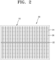
- FIG. 2 is a view showing the structure of a spray device 20 of a steaming apparatus according to the related art.
- the steaming apparatus includes a transfer apparatus 10 for transferring an object K to be cooked, the spray device 20 for providing steam to the object K to be cooked, and a main body frame 30.
- the transfer apparatus 10 is provided in the form of a net.
- the spray device 20 includes pipes and nozzles 26.
- the pipes of the spray device 20 include a center pipe 22 parallel to the traveling direction of the transfer apparatus 10, and a branch pipe 24 extending in a lateral direction from the center pipe 22 and intersecting the traveling direction of the transfer apparatus 10.
- the nozzles 26 are provided in the branch pipe 24.
- the main body frame 30 is provided as a containment vessel capable of withstanding high-temperature and high-pressure steam.
- the spray device 20 is disposed under the transfer apparatus (net) 10.
- the spray device 20, as illustrated in FIG. 2 includes branch type pipes, and the pipes and the nozzles 26 are regularly distributed throughout the entire area under the transfer apparatus 10.
- steam is sprayed in a direction toward the ground as indicated by an arrow L.
- the sprayed steam collides against the bottom portion of the main body frame 30 and then ascends to be brought into contact with the object K to be cooked located above the transfer apparatus 10.
- the existing steaming apparatus has many places to be cleaned because the pipes are distributed in a range corresponding to the entire area of the net. Furthermore, to access the pipes, the net of the steaming apparatus is entirely disassembled and reassembled after cleaning, it takes a considerable amount of manpower and time.
- a steaming apparatus includes: a main body frame; a transfer apparatus passing through the main body frame and moving an object to be cooked in a predetermined direction; a spray device arranged in both lateral portions of the transfer apparatus, wherein the spray device includes: a pipe portion extending in a direction parallel to a transport direction of the object to be cooked; and a nozzle portion connected to the pipe portion, and receiving and spraying stream to the outside, wherein the nozzle portion sprays steam in a direction toward the inside of the transfer apparatus from the outside of the transfer apparatus.
- the transfer apparatus may include a plurality of transfer lines, and the plurality of transfer lines may be arranged in a multilayer with a predetermined interval in a vertical direction.
- the plurality of transfer lines are provided in the form of a net.
- the pipe portion is arranged between the plurality of transfer lines in the vertical direction.
- the nozzle portion may include a plurality of nozzle portions, at least one of the plurality of nozzle portions may spray steam in a first direction, at least one of the plurality of nozzle portions may spray steam in a second direction, the first direction and a horizontal plane may have a first contained angle, the second direction and the horizontal plane may have a second contained angle, and the size of the first contained angle may be different from the size of the second contained angle.
- the nozzle portion may include a plurality of nozzle portions, each of the plurality of nozzle portions may include a spray hole, at least one of the plurality of nozzle portions may include a spray hole penetrating the at least one nozzle portion in the first direction, at least one of the plurality of nozzle portions may include a spray hole penetrating the at least one nozzle portion in the second direction, the first direction and the horizontal plane may have the first contained angle, the second direction and the horizontal plane may have the second contained angle, and the size of the first contained angle may be different from the size of the second contained angle.
- the nozzle portion may include a first nozzle portion, a second nozzle portion, and a third nozzle portion, the first nozzle portion may spray steam in a first direction, the second nozzle portion may spray steam in a second direction, the third nozzle portion may spray steam in a third direction, the first direction and the horizontal plane may have a first contained angle, the second direction and the horizontal plane may have a second contained angle, the third direction and the horizontal plane may have a third contained angle, and the first contained angle, the second contained angle, and the third contained angle may have different sizes from one another.
- the nozzle portion may include a first nozzle portion, a second nozzle portion, and a third nozzle portion
- the first nozzle portion may include a spray hole penetrating the first nozzle portion in a first direction
- the second nozzle portion may include a spray hole penetrating the second nozzle portion in a second direction
- the third nozzle portion may include a spray hole penetrating the third nozzle portion in a third direction
- the first direction may have a first contained angle downward from the horizontal plane
- the second direction may have a second contained angle downward from the horizontal plane
- the third direction may have a third contained angle downward from the horizontal plane
- the first contained angle, the second contained angle, and the third contained angle may have different sizes from one another.
- the sizes of the first contained angle, second contained angle, and third contained angle may be 0° to 90°.
- a plurality of nozzle arrays in each of which the first nozzle portion, the second nozzle portion, and the third nozzle portion are sequentially arranged, may be provided along the pipe portion.
- the steaming apparatus compared with the steaming apparatus according to the related art, has the effects, such as a reduced use amount of steam, a reduced management point according to the number of nozzles, unnecessity for disassembly during cleaning, reduced cleaning time and manpower, and prevention of contamination of a spray device due to falling organic materials.
- a steaming apparatus comprises: a main body frame; a transfer apparatus passing through the main body frame and moving an object to be cooked in a direction; a spray device arranged in both lateral portions of the transfer apparatus, wherein the spray device comprises: a pipe portion extending in a direction parallel to a transport direction of the object to be cooked; and a nozzle portion connected to the pipe portion, and receiving and spraying stream to the outside, wherein the nozzle portion sprays steam in a direction toward the inside of the transfer apparatus from the outside of the transfer apparatus.
- FIG. 3 is a view showing the structure of a steaming apparatus according to an embodiment of the present disclosure.
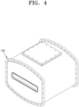
- FIG. 4 is a view showing an example of the appearance of a main body frame 100 of a steaming apparatus according to an embodiment of the present disclosure.
- FIG. 5 is a view showing the structure of a spray device 300 of a steaming apparatus according to an embodiment of the present disclosure.
- FIG. 6 is a view showing in detail the spray device 300 of a steaming apparatus according to an embodiment of the present disclosure, by enlarging a region A of FIG. 3 .
- the steaming apparatus includes: the main body frame 100; a transfer apparatus 200 passing through the main body frame 100 and moving an object to be cooked; and a spray device 300 arranged inside the main body frame 100 in a lateral portion of the transfer apparatus 200.
- the main body frame 100 has a container shape having an inner space.
- the inner space of the main body frame 100 may function as a steaming space filled with high-temperature and high-pressure steam.
- the main body frame 100 may include a material having rigidity. Accordingly, the high-temperature and high-pressure steam may fill the inside of the main body frame 100.
- An inlet and an outlet through which the transfer apparatus 200 described below passes may be provided in both end portions of the main body frame 100.
- a specific shape of the main body frame 100 is omitted, and the main body frame 100 may have any configuration in which the transfer apparatus 200 is movable and high-temperature and high-pressure steam is fillable.
- FIG. 4 illustrates an example of the appearance of the main body frame 100. However, the appearance and configuration of the main body frame 100 are not limited to those of FIG. 4 . Furthermore, although the internal structure of the main body frame 100 is not illustrated, the internal structure of the main body frame 100 would be obviously understood by a person skilled in the art.
- the transfer apparatus 200 is arranged in the main body frame 100.
- the transfer apparatus 200 passes through the main body frame 100.
- the transfer apparatus 200 is capable of moving an object to be cooked placed on the transfer apparatus 200.
- the transfer apparatus 200 may be an apparatus in the form of a conveyor belt traveling in a direction.
- the traveling direction of the transfer apparatus 200 is as indicated by an arrow F of FIGS. 3 and 5 .
- the transfer apparatus 200 may include a transfer line.
- the transfer line may include a belt line on which an object to be cooked is placed.
- the transfer line may be a net.
- an object to be cooked may be placed on a net. Accordingly, not only an upper surface of an object to be cooked, but also a lower surface of the object to be cooked may be in contact with steam. Accordingly, more effective steaming may be performed. In addition, a contact area between the object to be cooked and the transfer line may be reduced. Accordingly, the object to be cooked may be prevented from adhering to the transfer line.
- the transfer line may include a plurality of transfer lines.
- the plurality of transfer lines may be arranged in a multilayer with a predetermined interval in a vertical direction.
- the object to be cooked may be placed on each transfer line. Accordingly, a plurality of objects to be cooked may be simultaneously moved while steaming is performed.
- the spray device 300 includes: a pipe portion 310 extending in the same direction as a transport direction of the object to be cooked; and a nozzle portion 320 connected to the pipe portion 310 and receiving and spraying steam to the outside.
- the pipe portion 310 may include a pipe.
- the pipe portion 310 may be connected to an external steam generator to receive steam, and may transfer the received steam.
- the pipe portion 310 may be arranged in the lateral portion of the transfer apparatus 200.
- the lateral portion means an edge in either of both lateral directions.
- the pipe portion 310 may be arranged in an end portion of each of both lateral directions of the transfer apparatus 200, and the pipe portion 310 may extend in the same direction as the transport direction of the object to be cooked carried by the transfer apparatus 200.
- the pipe portion 310 may extend parallel to the extension direction (traveling direction) of the transfer apparatus 200 the pipe portion 310.
- the pipe portion 310 is illustrated as being located inside the edge of each of both lateral directions of the transfer apparatus 200.
- the present disclosure is not limited thereto.
- the pipe portion 310 may be located outside the edge of each of both lateral directions of the transfer apparatus 200, or the pipe portion 310 may be located to overlap the edge of each of both lateral directions of the transfer apparatus 200.
- the pipe portion 310 may be located between the transfer lines in a vertical direction.
- the nozzle portion 320 may be a nozzle device connected to the pipe portion 310.
- the nozzle portion 320 may include a plurality of nozzle portions. In other words, a plurality of nozzle portions 320 may be connected to one pipe portion 310.
- the nozzle portion 320 may be configured as a through-hole formed in the pipe portion 310.
- the nozzle portion 320 may be configured as a spray hole in the form of a through-hole penetrating a side surface of the pipe portion 310 and having a penetration direction (direction angle) in a specific direction.
- each nozzle portion 320 may be configured to include a nozzle body 322 protruding from the pipe portion 310 and a spray hole 324 formed in the nozzle body 322.
- the configuration of the nozzle portion 320 is not limited thereto, and any device capable of spraying stream delivered from the pipe portion 310 may have a certain configuration.
- the nozzle portion 320 is open in a direction toward the inside of the transfer apparatus 200. Accordingly, the nozzle portion 320 may spray steam in a direction toward the inside of the transfer apparatus 200, from the outside of the transfer apparatus 200.
- the steaming apparatus according to an embodiment of the present disclosure has the following effect.
- the pipe portion 310 and the nozzle portion 320 constituting the spray device 300 are arranged in both lateral portion of the transfer apparatus 200. Accordingly, steam is supplied by a side spraying method in which steam is sprayed from the left and right sides of the transfer apparatus 200 in a direction toward a central portion thereof.
- humidity and temperature of the inner space of the main body frame 100 may be quickly increased by steam, and unnecessary facility heat dissipation loss may be reduced. Furthermore, in the steaming apparatus according to an embodiment of the present disclosure, as a steam input amount may be reduced, steam efficiency may be improved compared with the steaming apparatus according to the related art.
- the steaming apparatus compared with the steaming apparatus according to the related art, as the facility heat dissipation loss is reduced and the steam input amount is reduced, the number of pipes and nozzles needed to supply steam to the same amount of objects to be steamed may be decreased.
- the spray device 300 is arranged in both lateral portions of the transfer apparatus 200. Accordingly, even when various by-products (e.g., various organic materials and the like caused from dumpling skin/fillings and the like) generated from an object to be cooked fall, the by-products do not affect the spray device 300.
- various by-products e.g., various organic materials and the like caused from dumpling skin/fillings and the like
- the nozzle portion 320 may include a plurality of nozzle portions.
- one pipe portion 310 may include a plurality of nozzle portions 320.
- the plurality of nozzle portions 320 may be spaced apart from each other with a distance therebetween.
- the distance between the nozzle portions 320 may be 8.5 cm.
- At least one of the plurality of nozzle portions 320 may spray steam in a first direction, and at least one of the plurality of nozzle portions 320 may spray steam in a second direction.
- the first direction and the horizontal plane have a first contained angle
- the second direction and the horizontal plane have a second contained angle
- the size of the first contained angle may be different from the size of the second contained angle.
- the horizontal plane may mean the ground plane or an upper surface of the transfer apparatus 200.
- the nozzle portion 320 includes at least one first nozzle portion 320A and at least one second nozzle portion 320B, and an open direction of the first nozzle portion 320A may be different from an open direction of the second nozzle portion 320B.
- the open direction means a penetration direction of a through-hole constituting the nozzle portion 320.
- a spraying direction of steam sprayed from the first nozzle portion 320A may be different from a spraying direction of steam sprayed from the second nozzle portion 320B.
- the nozzle portion 320 may include the nozzle portions 320 having different spraying directions in which the steam is sprayed.
- first nozzle portion 320A and the second nozzle portion 320B may have substantially the same configuration, and may be conceptually distinguished in terms of different open directions.
- the difference between the first nozzle portion 320A and the second nozzle portion 320B lies in the penetration direction of the through-hole, and the steam spraying direction thereby.
- the nozzle portion 320 spraying steam in a direction is not limited to the spraying of steam in a specific direction and within a specific space range. Fundamentally, the steam sprayed from the nozzle portion 320 diffuses.
- nozzle portions 320 having different spraying directions are provided, three-dimensional supply of steam may be possible, and the object to be cooked may be uniformly steamed. Accordingly, steam efficiency may be improved.
- the nozzle portion 320 may include the first nozzle portion 320A, the second nozzle portion 320B, and a third nozzle portion 320C.
- FIG. 6 is an enlarged view of the region A of FIG. 3
- FIG. 7 illustrates the pipe portion 310 viewed from a direction in which the nozzle portion 320
- FIG. 8 illustrates the respective formation positions of the nozzle portion 320 viewed from a direction X-X of FIG. 7 .
- the first nozzle portion 320A may spray steam in a first direction W1 as indicated by an arrow F1.
- the second nozzle portion 320B may spray steam in a second direction W2 as indicated by an arrow F2.
- the third nozzle portion 320C may spray steam in a third direction W3 as indicated by an arrow F3.
- the spraying of steam in a specific direction may mean that, as described above, the spray hole 324 provided in the nozzle portion heads a specific direction, and the spraying of steam is guided in the corresponding direction.
- the first direction W1 and a horizontal plane L may have a first contained angle A
- the second direction W2 and the horizontal plane L may have a second contained angle B
- the third direction W3 and the horizontal plane L may have a third contained angle C.
- the first contained angle A, the second contained angle B, and the third contained angle C may have different sizes.
- the nozzle portion 320 may perform spraying in at least three directions.
- the object to be cooked may be uniformly steamed. Accordingly, steam efficiency may be improved.
- the deviation in temperature in the left, middle, and right sides of the transfer apparatus 200 may be reduced.
- the first contained angle A, the second contained angle B, and the third contained angle C may respectively have sizes of 0 to 90°.
- the first contained angle A, the second contained angle B, and the third contained angle C may be 0°, 22.5°, and 45°, respectively.
- each contained angle is downward from the horizontal plane L, as illustrated in FIG. 8 .
- the first nozzle portion 320A may supply steam to an object to be cooked located at a relatively far position from the pipe portion 310 (that is, an object to be cooked located in the middle portion of the transfer line).
- the third nozzle portion 320C may supply steam to an object to be cooked located at a relatively near position from the pipe portion 310 (that is, an object to be cooked located outside the transfer line). Accordingly, a uniform steam effect may be provided to a plurality of objects to be cooked on the transfer line.
- the nozzle portion 320 includes a nozzle array 320L in which the first nozzle portion 320A, the second nozzle portion 320B, and the third nozzle portion 320C are sequentially arranged, and a plurality of nozzle arrays 320L may be provided along the pipe portion 310.
- the steam may be supplied uniformly and three-dimensionally, and the steam effect may be further improved.
- the steam supply pipes (the spray device 20) are distributed under the net (the transfer apparatus 10). Accordingly, in the steaming apparatus according to the related art, steam is sprayed in the ground direction, and the sprayed steam collides against a lower portion of the net and tens ascends and contacts the object to be cooked placed on an upper portion of the net. In addition, as the distance between the nozzle and the object to be cooked is relatively great, the steam is sprayed toward the floor and wall surfaces so that heat loss is generated. Accordingly, unnecessary facility heat dissipation loss occurs and the steam input amount is increased.
- the pipe portion 310 of the spray device 300 is installed in both sides of the transfer apparatus 200, and the pipe portion 310 extends in a direction parallel to the traveling direction of the transfer apparatus 200. Accordingly, in the steaming apparatus according to the present disclosure, steam is sprayed from both sides of the transfer apparatus 200, and thus, the sprayed steam may directly contact the object to be cooked at a relatively close distance. Accordingly, the facility heat dissipation loss may be reduced and the steam input amount may be reduced.
- the steam spraying angle of the nozzle portion 320 is a contained angle (0°, 22.5°, and 45° in an embodiment) from the horizontal plane, and as the nozzle portions 320 have a distance (8.5 cm in an embodiment) from each other, the deviation of the steam sprayed toward the left, right, and middle sides of the transfer apparatus 200 may be reduced.
- the basic unit of steam may be reduced by about 15-20% compared to the existing usage.
- the basic unit of steam means an amount of steam in kilograms per one ton of an object to be steamed.
- the basic unit of steam of the steaming apparatus according to the related art is 837.11 kg/ton
- the basic unit of steam of the steaming apparatus according to an embodiment of the present disclosure may be about 697.74 kg/ton.
- the amount of steam may be reduced. Accordingly, it may be checked that the usage amount of steam needed to maintain the same set temperature is reduced by about 16% in the steaming apparatus including the spray device 300 according to the present disclosure, compared with the steaming apparatus using the spray device 20 having the existing pipe structure.
- the transfer apparatus 10 As the steam supply pipes are distributed under the net (the transfer apparatus 10), when organic materials and the like generated from an object to be cooked fall, the organic materials may firmly adhere to the pipes and nozzles under the net. In this state, the organic materials may be carbonized by high temperature (99°C or more) and may remain. Accordingly, to prevent clogging of the nozzles and maintain the quality of products, it is necessary to periodically clean and manage the organic materials. In this state, the existing steaming apparatus has many places to be cleaned as illustrated in FIG. 2 because the pipes are distributed in a range corresponding to the entire area of the net. Furthermore, to access the pipes, the net of the steaming apparatus is entirely disassembled and reassembled after cleaning, it takes a considerable amount of manpower and time.
- the pipe portion 310 and the nozzle portion 320 are located in the left and right sides of the transfer apparatus 200, not thereunder. Accordingly, there may be no organic material accumulated on the pipe portion 310 and the nozzle portion 320, or the amount of organic materials accumulated on the pipe portion 310 and the nozzle portion 320 may be greatly reduced.
- the steaming apparatus according to an embodiment of the present disclosure during cleaning, without disassembling the transfer apparatus 200, only the pipe portion 310 and the nozzle portion 320 in the left and right sides of the transfer apparatus 200 are cleaned so that manpower and time needed for cleaning may be remarkably improved.
- Table 1 shows the tabulated effects of the steaming apparatus according to an embodiment of the present disclosure compared with the related art.
- Classification Related art before improvement of the spray device 300
- Embodiment after improvement of the spray device 300
- Effects Steam usage amount 1,350 KG/HR 1,134 KG/HR 16% improved
- Management points pipe length / number of nozzles
- 133 m / 968 units 25 m/ 344 units
- Cleaning method Cleaning after disassembling the transfer apparatus 10 (10 persons, 24 hr) Instant cleaning (4 persons, 4 hr) 97% improved
- the steaming apparatus according to an embodiment of the present disclosure compared with the steaming apparatus according to the related art, has the effects, such as a reduced use amount of steam, a reduced management point according to the number of nozzles, unnecessity for disassembly during cleaning, reduced cleaning time and manpower, and prevention of contamination of the spray device 300 due to falling organic materials.
Landscapes
- Engineering & Computer Science (AREA)
- Food Science & Technology (AREA)
- Life Sciences & Earth Sciences (AREA)
- Mechanical Engineering (AREA)
- Chemical & Material Sciences (AREA)
- Polymers & Plastics (AREA)
- Health & Medical Sciences (AREA)
- Nutrition Science (AREA)
- General Engineering & Computer Science (AREA)
- Combustion & Propulsion (AREA)
- Commercial Cooking Devices (AREA)
- General Preparation And Processing Of Foods (AREA)
- Seeds, Soups, And Other Foods (AREA)
Abstract
Description
- The present disclosure relates to a steaming apparatus, and more particularly, to a streaming apparatus in which, by spraying steam from a lateral portion of a transfer apparatus that transfers an object to be cooked, a steam input amount may be reduced, and facility operation and maintenance costs may be saved.
- A steaming apparatus is used to cook/sterilize an object to be cooked, for example, dumplings and the like, by applying high-temperature and high-pressure steam thereto. An object to be cooked may be cooked/sterilized in a steaming apparatus and then made into a product.
-
FIG. 1 is a view showing the structure of a steaming apparatus according to the related art, andFIG. 2 is a view showing the structure of aspray device 20 of a steaming apparatus according to the related art. - The steaming apparatus according to the related art includes a
transfer apparatus 10 for transferring an object K to be cooked, thespray device 20 for providing steam to the object K to be cooked, and amain body frame 30. - The
transfer apparatus 10 is provided in the form of a net. - The
spray device 20 includes pipes andnozzles 26. The pipes of thespray device 20 include acenter pipe 22 parallel to the traveling direction of thetransfer apparatus 10, and abranch pipe 24 extending in a lateral direction from thecenter pipe 22 and intersecting the traveling direction of thetransfer apparatus 10. Thenozzles 26 are provided in thebranch pipe 24. - The
main body frame 30 is provided as a containment vessel capable of withstanding high-temperature and high-pressure steam. - As illustrated in
FIG. 1 , in the steaming apparatus according to the related art, thespray device 20 is disposed under the transfer apparatus (net) 10. Thespray device 20, as illustrated inFIG. 2 , includes branch type pipes, and the pipes and thenozzles 26 are regularly distributed throughout the entire area under thetransfer apparatus 10. - Accordingly, in the steaming apparatus according to the related art, steam is sprayed in a direction toward the ground as indicated by an arrow L. The sprayed steam collides against the bottom portion of the
main body frame 30 and then ascends to be brought into contact with the object K to be cooked located above thetransfer apparatus 10. - Accordingly, in the steaming apparatus according to the related art, unnecessary facility heat dissipation loss occurs. In addition, as a distance between the
nozzles 26 and the object K to be cooked is relatively great, steam is sprayed toward the floor and wall surfaces so that heat loss is generated. - In other words, in the steaming apparatus according to the related art, only a portion of steam is transferred to the object K to be cooked, and the other portion is lost in the form of facility/conveyor heat dissipation loss or exhaustion loss. Thus, there are problems that a necessary steam input amount increases and facility operating expenses increase.
- Furthermore, in the steaming apparatus according to the related art, as steam supply pipes are distributed under the
transfer apparatus 10, when organic materials (oil, solids, etc.) and the like fall from the object K to be cooked, the materials may be firmly adhere to the pipes and nozzles under the net. In this state, the organic materials may be carbonized by high temperature (99°C or more) and may remain. Accordingly, there are problems that thenozzles 26 are clogged, or products are contaminated with carbide. - Accordingly, to prevent clogging of nozzles and maintain the quality of products, it is necessary to periodically clean and manage the organic materials. In this state, the existing steaming apparatus has many places to be cleaned because the pipes are distributed in a range corresponding to the entire area of the net. Furthermore, to access the pipes, the net of the steaming apparatus is entirely disassembled and reassembled after cleaning, it takes a considerable amount of manpower and time.
- Accordingly, there is a demand for the development of a steaming apparatus capable of reducing a steam input amount and saving operation and management costs.
- It is an objective of the present disclosure to provide a steaming apparatus in which, by spraying steam from a lateral portion of a transfer apparatus that transfers an object to be cooked, a steam input amount may be reduced and facility operation and maintenance costs may be saved.
- According to an aspect of the disclosure, a steaming apparatus includes: a main body frame; a transfer apparatus passing through the main body frame and moving an object to be cooked in a predetermined direction; a spray device arranged in both lateral portions of the transfer apparatus, wherein the spray device includes: a pipe portion extending in a direction parallel to a transport direction of the object to be cooked; and a nozzle portion connected to the pipe portion, and receiving and spraying stream to the outside, wherein the nozzle portion sprays steam in a direction toward the inside of the transfer apparatus from the outside of the transfer apparatus.
- According to an embodiment, the transfer apparatus may include a plurality of transfer lines, and the plurality of transfer lines may be arranged in a multilayer with a predetermined interval in a vertical direction.
- According to an embodiment, the plurality of transfer lines are provided in the form of a net.
- According to an embodiment, the pipe portion is arranged between the plurality of transfer lines in the vertical direction.
- According to an embodiment, the nozzle portion may include a plurality of nozzle portions, at least one of the plurality of nozzle portions may spray steam in a first direction, at least one of the plurality of nozzle portions may spray steam in a second direction, the first direction and a horizontal plane may have a first contained angle, the second direction and the horizontal plane may have a second contained angle, and the size of the first contained angle may be different from the size of the second contained angle.
- According to an embodiment, the nozzle portion may include a plurality of nozzle portions, each of the plurality of nozzle portions may include a spray hole, at least one of the plurality of nozzle portions may include a spray hole penetrating the at least one nozzle portion in the first direction, at least one of the plurality of nozzle portions may include a spray hole penetrating the at least one nozzle portion in the second direction, the first direction and the horizontal plane may have the first contained angle, the second direction and the horizontal plane may have the second contained angle, and the size of the first contained angle may be different from the size of the second contained angle.
- According to an embodiment, the nozzle portion may include a first nozzle portion, a second nozzle portion, and a third nozzle portion, the first nozzle portion may spray steam in a first direction, the second nozzle portion may spray steam in a second direction, the third nozzle portion may spray steam in a third direction, the first direction and the horizontal plane may have a first contained angle, the second direction and the horizontal plane may have a second contained angle, the third direction and the horizontal plane may have a third contained angle, and the first contained angle, the second contained angle, and the third contained angle may have different sizes from one another.
- According to an embodiment, the nozzle portion may include a first nozzle portion, a second nozzle portion, and a third nozzle portion, the first nozzle portion may include a spray hole penetrating the first nozzle portion in a first direction, the second nozzle portion may include a spray hole penetrating the second nozzle portion in a second direction, the third nozzle portion may include a spray hole penetrating the third nozzle portion in a third direction, the first direction may have a first contained angle downward from the horizontal plane, the second direction may have a second contained angle downward from the horizontal plane, the third direction may have a third contained angle downward from the horizontal plane, and the first contained angle, the second contained angle, and the third contained angle may have different sizes from one another.
- According to an embodiment, the sizes of the first contained angle, second contained angle, and third contained angle may be 0° to 90°.
- According to an embodiment, in the nozzle portion, a plurality of nozzle arrays, in each of which the first nozzle portion, the second nozzle portion, and the third nozzle portion are sequentially arranged, may be provided along the pipe portion.
- The steaming apparatus according to an embodiment of the present disclosure, compared with the steaming apparatus according to the related art, has the effects, such as a reduced use amount of steam, a reduced management point according to the number of nozzles, unnecessity for disassembly during cleaning, reduced cleaning time and manpower, and prevention of contamination of a spray device due to falling organic materials.
-
-
FIG. 1 is a view showing the structure of a steaming apparatus according to the related art. -
FIG. 2 is a view showing the structure of a spray device of a steaming apparatus according to the related art. -
FIG. 3 is a view showing the structure of a steaming apparatus according to an embodiment of the present disclosure. -
FIG. 4 is a view showing the appearance of a main body frame of a steaming apparatus according to an embodiment of the present disclosure. -
FIG. 5 is a view showing the structure of a spray device of a steaming apparatus according to an embodiment of the present disclosure. -
FIG. 6 is a view showing, in detail, the structure of a spray device of a steaming apparatus according to an embodiment of the present disclosure, by enlarging a region A ofFIG. 3 . -
FIG. 7 illustrates a pipe portion viewed from a direction in which a nozzle portion is formed, andFIG. 8 shows the formation locations of each nozzle portion when viewed from a direction X-X ofFIG. 7 . -
FIG. 9 illustrates the structure of a spray device according to an embodiment of the present disclosure. - A steaming apparatus according to an embodiment of the disclosure comprises: a main body frame; a transfer apparatus passing through the main body frame and moving an object to be cooked in a direction; a spray device arranged in both lateral portions of the transfer apparatus, wherein the spray device comprises: a pipe portion extending in a direction parallel to a transport direction of the object to be cooked; and a nozzle portion connected to the pipe portion, and receiving and spraying stream to the outside, wherein the nozzle portion sprays steam in a direction toward the inside of the transfer apparatus from the outside of the transfer apparatus.
- Hereinafter, an embodiment according to the present disclosure is described with reference to the accompanying drawings.
-
FIG. 3 is a view showing the structure of a steaming apparatus according to an embodiment of the present disclosure.FIG. 4 is a view showing an example of the appearance of amain body frame 100 of a steaming apparatus according to an embodiment of the present disclosure.FIG. 5 is a view showing the structure of aspray device 300 of a steaming apparatus according to an embodiment of the present disclosure.FIG. 6 is a view showing in detail thespray device 300 of a steaming apparatus according to an embodiment of the present disclosure, by enlarging a region A ofFIG. 3 . - The steaming apparatus according to an embodiment of the present disclosure includes: the
main body frame 100; atransfer apparatus 200 passing through themain body frame 100 and moving an object to be cooked; and aspray device 300 arranged inside themain body frame 100 in a lateral portion of thetransfer apparatus 200. - The
main body frame 100 has a container shape having an inner space. The inner space of themain body frame 100 may function as a steaming space filled with high-temperature and high-pressure steam. Themain body frame 100 may include a material having rigidity. Accordingly, the high-temperature and high-pressure steam may fill the inside of themain body frame 100. An inlet and an outlet through which thetransfer apparatus 200 described below passes may be provided in both end portions of themain body frame 100. In the drawings, a specific shape of themain body frame 100 is omitted, and themain body frame 100 may have any configuration in which thetransfer apparatus 200 is movable and high-temperature and high-pressure steam is fillable.FIG. 4 illustrates an example of the appearance of themain body frame 100. However, the appearance and configuration of themain body frame 100 are not limited to those ofFIG. 4 . Furthermore, although the internal structure of themain body frame 100 is not illustrated, the internal structure of themain body frame 100 would be obviously understood by a person skilled in the art. - The
transfer apparatus 200 is arranged in themain body frame 100. Thetransfer apparatus 200 passes through themain body frame 100. - The
transfer apparatus 200 is capable of moving an object to be cooked placed on thetransfer apparatus 200. According to an embodiment, thetransfer apparatus 200 may be an apparatus in the form of a conveyor belt traveling in a direction. The traveling direction of thetransfer apparatus 200 is as indicated by an arrow F ofFIGS. 3 and5 . - According to an embodiment, the
transfer apparatus 200 may include a transfer line. The transfer line may include a belt line on which an object to be cooked is placed. - According to an embodiment, the transfer line may be a net. In other words, an object to be cooked may be placed on a net. Accordingly, not only an upper surface of an object to be cooked, but also a lower surface of the object to be cooked may be in contact with steam. Accordingly, more effective steaming may be performed. In addition, a contact area between the object to be cooked and the transfer line may be reduced. Accordingly, the object to be cooked may be prevented from adhering to the transfer line.
- The transfer line may include a plurality of transfer lines. The plurality of transfer lines may be arranged in a multilayer with a predetermined interval in a vertical direction. The object to be cooked may be placed on each transfer line. Accordingly, a plurality of objects to be cooked may be simultaneously moved while steaming is performed.
- The
spray device 300 includes: apipe portion 310 extending in the same direction as a transport direction of the object to be cooked; and anozzle portion 320 connected to thepipe portion 310 and receiving and spraying steam to the outside. - The
pipe portion 310 may include a pipe. Thepipe portion 310 may be connected to an external steam generator to receive steam, and may transfer the received steam. - According to an embodiment, as illustrated in
FIG. 3 , thepipe portion 310 may be arranged in the lateral portion of thetransfer apparatus 200. The lateral portion means an edge in either of both lateral directions. In other words, thepipe portion 310 may be arranged in an end portion of each of both lateral directions of thetransfer apparatus 200, and thepipe portion 310 may extend in the same direction as the transport direction of the object to be cooked carried by thetransfer apparatus 200. In other words, thepipe portion 310 may extend parallel to the extension direction (traveling direction) of thetransfer apparatus 200 thepipe portion 310. - Here, in
FIG. 3 , thepipe portion 310 is illustrated as being located inside the edge of each of both lateral directions of thetransfer apparatus 200. However, the present disclosure is not limited thereto. In other words, thepipe portion 310 may be located outside the edge of each of both lateral directions of thetransfer apparatus 200, or thepipe portion 310 may be located to overlap the edge of each of both lateral directions of thetransfer apparatus 200. - In addition, as described above, when a plurality of transfer lines are provided, the
pipe portion 310 may be located between the transfer lines in a vertical direction. - The
nozzle portion 320 may be a nozzle device connected to thepipe portion 310. Thenozzle portion 320 may include a plurality of nozzle portions. In other words, a plurality ofnozzle portions 320 may be connected to onepipe portion 310. - As illustrated in
FIG. 6 to 8 , according to an embodiment of the present disclosure, thenozzle portion 320 may be configured as a through-hole formed in thepipe portion 310. In other words, according to an embodiment, thenozzle portion 320 may be configured as a spray hole in the form of a through-hole penetrating a side surface of thepipe portion 310 and having a penetration direction (direction angle) in a specific direction. - Meanwhile, as illustrated in
FIG. 9 , according to an embodiment of the present disclosure, eachnozzle portion 320 may be configured to include anozzle body 322 protruding from thepipe portion 310 and aspray hole 324 formed in thenozzle body 322. In other words, the configuration of thenozzle portion 320 is not limited thereto, and any device capable of spraying stream delivered from thepipe portion 310 may have a certain configuration. - The
nozzle portion 320 is open in a direction toward the inside of thetransfer apparatus 200. Accordingly, thenozzle portion 320 may spray steam in a direction toward the inside of thetransfer apparatus 200, from the outside of thetransfer apparatus 200. - When the steaming apparatus according to the related art, in which the
spray device 300 is disposed under thetransfer apparatus 200 to provide steam in an upward direction, is compared with the steaming apparatus according to an embodiment of the present disclosure, the steaming apparatus according to an embodiment of the present disclosure has the following effect. - As described above, in an embodiment of the disclosure, the
pipe portion 310 and thenozzle portion 320 constituting thespray device 300 are arranged in both lateral portion of thetransfer apparatus 200. Accordingly, steam is supplied by a side spraying method in which steam is sprayed from the left and right sides of thetransfer apparatus 200 in a direction toward a central portion thereof. - Accordingly, in the steaming apparatus according to an embodiment of the present disclosure, humidity and temperature of the inner space of the
main body frame 100 may be quickly increased by steam, and unnecessary facility heat dissipation loss may be reduced. Furthermore, in the steaming apparatus according to an embodiment of the present disclosure, as a steam input amount may be reduced, steam efficiency may be improved compared with the steaming apparatus according to the related art. - Furthermore, in the steaming apparatus according to an embodiment of the present disclosure, compared with the steaming apparatus according to the related art, as the facility heat dissipation loss is reduced and the steam input amount is reduced, the number of pipes and nozzles needed to supply steam to the same amount of objects to be steamed may be decreased.
- In addition, in the steaming apparatus according to an embodiment of the present disclosure, the
spray device 300 is arranged in both lateral portions of thetransfer apparatus 200. Accordingly, even when various by-products (e.g., various organic materials and the like caused from dumpling skin/fillings and the like) generated from an object to be cooked fall, the by-products do not affect thespray device 300. - Accordingly, the facility operation and maintenance costs of the steaming apparatus may be saved.
- According to an embodiment, the
nozzle portion 320 may include a plurality of nozzle portions. In other words, onepipe portion 310 may include a plurality ofnozzle portions 320. In this state, the plurality ofnozzle portions 320 may be spaced apart from each other with a distance therebetween. For example, the distance between thenozzle portions 320 may be 8.5 cm. - In this state, at least one of the plurality of
nozzle portions 320 may spray steam in a first direction, and at least one of the plurality ofnozzle portions 320 may spray steam in a second direction. In this state, the first direction and the horizontal plane have a first contained angle, the second direction and the horizontal plane have a second contained angle, and the size of the first contained angle may be different from the size of the second contained angle. The horizontal plane may mean the ground plane or an upper surface of thetransfer apparatus 200. - In other words, it may be described that the
nozzle portion 320 includes at least onefirst nozzle portion 320A and at least onesecond nozzle portion 320B, and an open direction of thefirst nozzle portion 320A may be different from an open direction of thesecond nozzle portion 320B. - Here, the open direction means a penetration direction of a through-hole constituting the
nozzle portion 320. As thefirst nozzle portion 320A and thesecond nozzle portion 320B have different open directions, a spraying direction of steam sprayed from thefirst nozzle portion 320A may be different from a spraying direction of steam sprayed from thesecond nozzle portion 320B. In other words, thenozzle portion 320 may include thenozzle portions 320 having different spraying directions in which the steam is sprayed. - In other words, the
first nozzle portion 320A and thesecond nozzle portion 320B may have substantially the same configuration, and may be conceptually distinguished in terms of different open directions. In other words, the difference between thefirst nozzle portion 320A and thesecond nozzle portion 320B lies in the penetration direction of the through-hole, and the steam spraying direction thereby. - Here, the
nozzle portion 320 spraying steam in a direction is not limited to the spraying of steam in a specific direction and within a specific space range. Fundamentally, the steam sprayed from thenozzle portion 320 diffuses. - As in the embodiment described above, as the
nozzle portions 320 having different spraying directions are provided, three-dimensional supply of steam may be possible, and the object to be cooked may be uniformly steamed. Accordingly, steam efficiency may be improved. - According to a more detailed embodiment, as illustrated in
FIG. 6 to 8 , thenozzle portion 320 may include thefirst nozzle portion 320A, thesecond nozzle portion 320B, and athird nozzle portion 320C.FIG. 6 is an enlarged view of the region A ofFIG. 3 ,FIG. 7 illustrates thepipe portion 310 viewed from a direction in which thenozzle portion 320, andFIG. 8 illustrates the respective formation positions of thenozzle portion 320 viewed from a direction X-X ofFIG. 7 . - In this state, the
first nozzle portion 320A may spray steam in a first direction W1 as indicated by an arrow F1. In addition, thesecond nozzle portion 320B may spray steam in a second direction W2 as indicated by an arrow F2. In addition, thethird nozzle portion 320C may spray steam in a third direction W3 as indicated by an arrow F3. - Here, the spraying of steam in a specific direction may mean that, as described above, the
spray hole 324 provided in the nozzle portion heads a specific direction, and the spraying of steam is guided in the corresponding direction. - As illustrated in
FIG. 8 , the first direction W1 and a horizontal plane L may have a first contained angle A, the second direction W2 and the horizontal plane L may have a second contained angle B, and the third direction W3 and the horizontal plane L may have a third contained angle C. The first contained angle A, the second contained angle B, and the third contained angle C may have different sizes. - Accordingly, the
nozzle portion 320 may perform spraying in at least three directions. - Accordingly, three-dimensional supply of steam may be possible, and the object to be cooked may be uniformly steamed. Accordingly, steam efficiency may be improved. In particular, when there are three steam spraying directions as in the embodiment, the deviation in temperature in the left, middle, and right sides of the
transfer apparatus 200 may be reduced. - According to an embodiment, in detail, the first contained angle A, the second contained angle B, and the third contained angle C may respectively have sizes of 0 to 90°.
- According to an embodiment, the first contained angle A, the second contained angle B, and the third contained angle C may be 0°, 22.5°, and 45°, respectively.
- However, the disclosure is not limited thereto, and each contained angle may be changed depending on the process conditions and the like.
- Here, each contained angle is downward from the horizontal plane L, as illustrated in
FIG. 8 . - Accordingly, the
first nozzle portion 320A may supply steam to an object to be cooked located at a relatively far position from the pipe portion 310 (that is, an object to be cooked located in the middle portion of the transfer line). Thethird nozzle portion 320C may supply steam to an object to be cooked located at a relatively near position from the pipe portion 310 (that is, an object to be cooked located outside the transfer line). Accordingly, a uniform steam effect may be provided to a plurality of objects to be cooked on the transfer line. - Furthermore, according to an embodiment, the
nozzle portion 320 includes anozzle array 320L in which thefirst nozzle portion 320A, thesecond nozzle portion 320B, and thethird nozzle portion 320C are sequentially arranged, and a plurality ofnozzle arrays 320L may be provided along thepipe portion 310. - Accordingly, the steam may be supplied uniformly and three-dimensionally, and the steam effect may be further improved.
- The comparison and contrast between the steaming apparatus according to an embodiment of the present disclosure and the steaming apparatus according to the related art are described below.
- In the steaming apparatus according to the related art, the steam supply pipes (the spray device 20) are distributed under the net (the transfer apparatus 10). Accordingly, in the steaming apparatus according to the related art, steam is sprayed in the ground direction, and the sprayed steam collides against a lower portion of the net and tens ascends and contacts the object to be cooked placed on an upper portion of the net. In addition, as the distance between the nozzle and the object to be cooked is relatively great, the steam is sprayed toward the floor and wall surfaces so that heat loss is generated. Accordingly, unnecessary facility heat dissipation loss occurs and the steam input amount is increased.
- In contrast, in the steaming apparatus according to an embodiment of the present disclosure, the
pipe portion 310 of thespray device 300 is installed in both sides of thetransfer apparatus 200, and thepipe portion 310 extends in a direction parallel to the traveling direction of thetransfer apparatus 200. Accordingly, in the steaming apparatus according to the present disclosure, steam is sprayed from both sides of thetransfer apparatus 200, and thus, the sprayed steam may directly contact the object to be cooked at a relatively close distance. Accordingly, the facility heat dissipation loss may be reduced and the steam input amount may be reduced. - Furthermore, in the steaming apparatus according to an embodiment of the present disclosure, the steam spraying angle of the
nozzle portion 320 is a contained angle (0°, 22.5°, and 45° in an embodiment) from the horizontal plane, and as thenozzle portions 320 have a distance (8.5 cm in an embodiment) from each other, the deviation of the steam sprayed toward the left, right, and middle sides of thetransfer apparatus 200 may be reduced. - Accordingly, the basic unit of steam may be reduced by about 15-20% compared to the existing usage. Here, the basic unit of steam means an amount of steam in kilograms per one ton of an object to be steamed.
- In other words, while the basic unit of steam of the steaming apparatus according to the related art is 837.11 kg/ton, the basic unit of steam of the steaming apparatus according to an embodiment of the present disclosure may be about 697.74 kg/ton. In other words, according to the steaming apparatus according to an embodiment of the present disclosure, the amount of steam may be reduced. Accordingly, it may be checked that the usage amount of steam needed to maintain the same set temperature is reduced by about 16% in the steaming apparatus including the
spray device 300 according to the present disclosure, compared with the steaming apparatus using thespray device 20 having the existing pipe structure. - Furthermore, in the steaming apparatus according to an embodiment of the present disclosure, as the number of the
nozzle portions 320 decreases, ease of operation and management of the steaming apparatus may be drastically improved. - In the steaming apparatus according to the related art, as the steam supply pipes are distributed under the net (the transfer apparatus 10), when organic materials and the like generated from an object to be cooked fall, the organic materials may firmly adhere to the pipes and nozzles under the net. In this state, the organic materials may be carbonized by high temperature (99°C or more) and may remain. Accordingly, to prevent clogging of the nozzles and maintain the quality of products, it is necessary to periodically clean and manage the organic materials. In this state, the existing steaming apparatus has many places to be cleaned as illustrated in
FIG. 2 because the pipes are distributed in a range corresponding to the entire area of the net. Furthermore, to access the pipes, the net of the steaming apparatus is entirely disassembled and reassembled after cleaning, it takes a considerable amount of manpower and time. - In contrast, in the steaming apparatus according to an embodiment of the present disclosure, the
pipe portion 310 and thenozzle portion 320 are located in the left and right sides of thetransfer apparatus 200, not thereunder. Accordingly, there may be no organic material accumulated on thepipe portion 310 and thenozzle portion 320, or the amount of organic materials accumulated on thepipe portion 310 and thenozzle portion 320 may be greatly reduced. In addition, in the steaming apparatus according to an embodiment of the present disclosure, during cleaning, without disassembling thetransfer apparatus 200, only thepipe portion 310 and thenozzle portion 320 in the left and right sides of thetransfer apparatus 200 are cleaned so that manpower and time needed for cleaning may be remarkably improved. - Table 1 below shows the tabulated effects of the steaming apparatus according to an embodiment of the present disclosure compared with the related art.
[Table 1] Classification Related art (before improvement of the spray device 300) Embodiment (after improvement of the spray device 300) Effects Steam usage amount 1,350 KG/HR 1,134 KG/HR 16% improved Management points (pipe length / number of nozzles) 133 m / 968 units 25 m/ 344 units Reduced number of places requiring cleaning, and improvement of contamination due to falling organic materials Cleaning method Cleaning after disassembling the transfer apparatus 10 (10 persons, 24 hr) Instant cleaning (4 persons, 4 hr) 97% improved - As shown in the table above, it may be checked that the steaming apparatus according to an embodiment of the present disclosure, compared with the steaming apparatus according to the related art, has the effects, such as a reduced use amount of steam, a reduced management point according to the number of nozzles, unnecessity for disassembly during cleaning, reduced cleaning time and manpower, and prevention of contamination of the
spray device 300 due to falling organic materials. - While the disclosure has been particularly shown and described with reference to preferred embodiments using specific terminologies, the embodiments and terminologies should be considered in descriptive sense only and not for purposes of limitation. Therefore, it will be understood by those of ordinary skill in the art that various changes in form and details may be made therein without departing from the spirit and scope of the disclosure as defined by the following claims.
Claims (6)
- A steaming apparatus comprising:a main body frame;a transfer apparatus passing through the main body frame and moving an object to be cooked in a predetermined direction;a spray device arranged in both lateral portions of the transfer apparatus,wherein the spray device comprises:a pipe portion extending in a direction parallel to a transport direction of the object to be cooked; anda nozzle portion connected to the pipe portion, and receiving and spraying stream to an outside,wherein the nozzle portion sprays steam in a direction toward an inside of the transfer apparatus from an outside of the transfer apparatus,wherein the transfer apparatus comprises:a plurality of transfer lines; andthe plurality of transfer lines are arranged in a multilayer with a predetermined interval in a vertical direction, andwherein the pipe portion is arranged between the plurality of transfer lines in the vertical direction,wherein the nozzle portion comprises a plurality of nozzle portions,at least one of the plurality of nozzle portions sprays steam in a first direction,at least one of the plurality of nozzle portions sprays steam in a second direction,the first direction and a horizontal plane have a first contained angle,the second direction and the horizontal plane have a second contained angle, andthe size of the first contained angle is different from the size of the second contained angle.
- The steaming apparatus of claim 1, wherein the nozzle portion comprises a plurality of nozzle portions,each of the plurality of nozzle portions includes a spray hole,at least one of the plurality of nozzle portions includes a spray hole penetrating the at least one nozzle portion in the first direction,at least one of the plurality of nozzle portions includes a spray hole penetrating the at least one nozzle portion in the second direction,the first direction and the horizontal plane have the first contained angle,the second direction and the horizontal plane have the second contained angle, andthe size of the first contained angle is different from the size of the second contained angle.
- The steaming apparatus of claim 1, wherein the nozzle portion comprises a first nozzle portion, a second nozzle portion, and a third nozzle portion,the first nozzle portion sprays steam in a first direction,the second nozzle portion sprays steam in a second direction,the third nozzle portion sprays steam in a third direction,the first direction and the horizontal plane have a first contained angle,the second direction and the horizontal plane have a second contained angle,the third direction and the horizontal plane have a third contained angle, andthe first contained angle, the second contained angle, and the third contained angle have different sizes from one another.
- The steaming apparatus of claim 1, wherein the nozzle portion comprises a first nozzle portion, a second nozzle portion, and a third nozzle portion,the first nozzle portion includes a spray hole penetrating the first nozzle in a first direction,the second nozzle portion includes a spray hole penetrating the second nozzle in a second direction,the third nozzle portion includes a spray hole penetrating the third nozzle in a third direction,the first direction has a first contained angle downward from the horizontal plane,the second direction has a second contained angle downward from the horizontal plane,the third direction has a third contained angle downward from the horizontal plane, andthe first contained angle, the second contained angle, and the third contained angle have different sizes from one another.
- The steaming apparatus of claim 3 or 4, wherein the sizes of the first contained angle, the second contained angle, and the third contained angle are 0° to 90°.
- The steaming apparatus of claim 3 or 4, wherein, in the nozzle portion, a nozzle array in which the first nozzle portion, the second nozzle portion, and the third nozzle portion are sequentially arranged is repeatedly provided along the pipe portion.
Applications Claiming Priority (2)
| Application Number | Priority Date | Filing Date | Title |
|---|---|---|---|
| KR1020200127549A KR102335272B1 (en) | 2020-09-29 | 2020-09-29 | Steaming apparatus |
| PCT/KR2021/013335 WO2022071750A1 (en) | 2020-09-29 | 2021-09-29 | Steaming apparatus |
Publications (2)
| Publication Number | Publication Date |
|---|---|
| EP4223142A1 true EP4223142A1 (en) | 2023-08-09 |
| EP4223142A4 EP4223142A4 (en) | 2024-10-30 |
Family
ID=78866454
Family Applications (1)
| Application Number | Title | Priority Date | Filing Date |
|---|---|---|---|
| EP21876025.4A Pending EP4223142A4 (en) | 2020-09-29 | 2021-09-29 | VAPORIZING DEVICE |
Country Status (7)
| Country | Link |
|---|---|
| US (1) | US20230320513A1 (en) |
| EP (1) | EP4223142A4 (en) |
| JP (1) | JP7446520B2 (en) |
| KR (1) | KR102335272B1 (en) |
| CN (1) | CN115884686B (en) |
| AU (1) | AU2021351595B2 (en) |
| WO (1) | WO2022071750A1 (en) |
Families Citing this family (1)
| Publication number | Priority date | Publication date | Assignee | Title |
|---|---|---|---|---|
| KR102436477B1 (en) * | 2021-10-28 | 2022-08-26 | 씨제이제일제당 (주) | Food steaming apparatus and food processing system |
Family Cites Families (17)
| Publication number | Priority date | Publication date | Assignee | Title |
|---|---|---|---|---|
| DE566984C (en) * | 1933-01-03 | Karl Kroll | Baking method for bread containing rye in ovens with moving plates | |
| GB646550A (en) * | 1948-06-11 | 1950-11-22 | Baker Perkins Ltd | Improvements in and relating to bakers' and like ovens |
| US2767667A (en) * | 1950-08-22 | 1956-10-23 | Spooner Food Machinery Enginee | Steaming of food products |
| NL1005803C2 (en) * | 1997-04-11 | 1998-10-14 | Koppens Convenience Food Syste | Steam oven. |
| JP2002034482A (en) * | 2000-07-28 | 2002-02-05 | Fuji Seisakusho:Kk | Apparatus for gelatinizing noodle |
| JP3923791B2 (en) * | 2001-11-30 | 2007-06-06 | 英治 村田 | Steaming equipment |
| JP2007029509A (en) * | 2005-07-28 | 2007-02-08 | Sanden Corp | Vapor jet nozzle |
| KR101006641B1 (en) * | 2008-10-24 | 2011-01-10 | 예인해 | Fish paste manufacturing device |
| US8646373B1 (en) * | 2009-05-04 | 2014-02-11 | Nova Research, Inc. | Blast wave effects reduction system |
| US8646383B1 (en) * | 2009-09-15 | 2014-02-11 | David Howard | Spiral oven apparatus and method of cooking |
| KR101434754B1 (en) * | 2012-12-07 | 2014-08-29 | 김상호 | Electric steamer |
| JP6407034B2 (en) * | 2015-01-09 | 2018-10-17 | 高技工業株式会社 | Heat treatment device |
| KR20170056738A (en) * | 2015-11-13 | 2017-05-24 | 심동복 | Cyclone injection type Steam nozzle of instant food cooking equipment |
| KR101732846B1 (en) | 2016-03-16 | 2017-05-04 | 주식회사 에프시이엔지 | dumpling's steaming boil apparatus |
| NL2020337B1 (en) * | 2017-01-30 | 2019-02-25 | John Bean Technologies Corp | Commercial scale sous-vide system and method |
| KR102093648B1 (en) * | 2018-08-07 | 2020-03-26 | (주)한솔기계 | Dumpling aftertreatment device |
| KR20200033827A (en) * | 2020-03-19 | 2020-03-30 | (주)한솔기계 | Dumpling aftertreatment device |
-
2020
- 2020-09-29 KR KR1020200127549A patent/KR102335272B1/en active Active
-
2021
- 2021-09-29 EP EP21876025.4A patent/EP4223142A4/en active Pending
- 2021-09-29 US US18/021,273 patent/US20230320513A1/en active Pending
- 2021-09-29 WO PCT/KR2021/013335 patent/WO2022071750A1/en not_active Ceased
- 2021-09-29 JP JP2023513594A patent/JP7446520B2/en active Active
- 2021-09-29 CN CN202180050719.4A patent/CN115884686B/en active Active
- 2021-09-29 AU AU2021351595A patent/AU2021351595B2/en active Active
Also Published As
| Publication number | Publication date |
|---|---|
| EP4223142A4 (en) | 2024-10-30 |
| JP2023540048A (en) | 2023-09-21 |
| AU2021351595A1 (en) | 2023-04-13 |
| US20230320513A1 (en) | 2023-10-12 |
| KR102335272B1 (en) | 2021-12-03 |
| AU2021351595B2 (en) | 2025-02-13 |
| JP7446520B2 (en) | 2024-03-08 |
| CN115884686A (en) | 2023-03-31 |
| CN115884686B (en) | 2024-12-27 |
| WO2022071750A1 (en) | 2022-04-07 |
Similar Documents
| Publication | Publication Date | Title |
|---|---|---|
| US5497798A (en) | Conveyor dishwasher | |
| US20230320513A1 (en) | Steaming apparatus | |
| EP0238238B1 (en) | Improvements in and relating to a powder booth | |
| US3703382A (en) | Method of coating edible food articles | |
| KR20160093602A (en) | Method for cleaning a nozzle arrangement in a spray drying apparatus, and spray drying apparatus for carrying out the method | |
| DE2735532A1 (en) | LONG SPRAY MACHINE FOR CLEANING GLASS CONTAINERS | |
| RU97104884A (en) | DEVICE FOR COATING PROCESSED GOODS BY PAINT BY SPRAYING | |
| AU648700B2 (en) | Conveyor belt for conveying can bodies in can body washing and surface treatment equipment | |
| JP2020104910A (en) | Container packaging device | |
| KR102279573B1 (en) | Automatic washing machine | |
| JPH03254879A (en) | Dewatering dryyer | |
| US11988449B2 (en) | Spray drying apparatus with a plenum chamber below a perforated bottom of a spray drying chamber | |
| CN215531483U (en) | Intelligent processing assembly line for postharvest honeydew melons | |
| CN214413820U (en) | Egg cleaning and disinfecting equipment | |
| US20190387719A1 (en) | Apparatus and method for washing shell eggs | |
| CN112038257B (en) | Cleaning equipment | |
| CN222249017U (en) | Fresh-cut vegetable processing device | |
| CN222077386U (en) | A multi-cylinder cleaning and multi-layer conveying agricultural product cleaning machine | |
| CN220343236U (en) | Novel clear excrement equipment of meat chicken | |
| CN220255597U (en) | Tartary buckwheat surface shell expansion device based on cold water spraying | |
| CN216013172U (en) | Egg surface crack monitoring devices | |
| CN216392939U (en) | Egg shell sterilizing machine for early-stage egg yolk immunoglobulin powder preparation | |
| US10051999B2 (en) | Apparatus for breaking eggs and method for cleaning | |
| JPH0489714A (en) | Alignment and supply device for cylinder shaped kneaded product | |
| JPH0317985Y2 (en) |
Legal Events
| Date | Code | Title | Description |
|---|---|---|---|
| STAA | Information on the status of an ep patent application or granted ep patent |
Free format text: STATUS: THE INTERNATIONAL PUBLICATION HAS BEEN MADE |
|
| PUAI | Public reference made under article 153(3) epc to a published international application that has entered the european phase |
Free format text: ORIGINAL CODE: 0009012 |
|
| STAA | Information on the status of an ep patent application or granted ep patent |
Free format text: STATUS: REQUEST FOR EXAMINATION WAS MADE |
|
| 17P | Request for examination filed |
Effective date: 20230216 |
|
| AK | Designated contracting states |
Kind code of ref document: A1 Designated state(s): AL AT BE BG CH CY CZ DE DK EE ES FI FR GB GR HR HU IE IS IT LI LT LU LV MC MK MT NL NO PL PT RO RS SE SI SK SM TR |
|
| DAV | Request for validation of the european patent (deleted) | ||
| DAX | Request for extension of the european patent (deleted) | ||
| A4 | Supplementary search report drawn up and despatched |
Effective date: 20240926 |
|
| RIC1 | Information provided on ipc code assigned before grant |
Ipc: B05B 1/20 20060101ALI20240920BHEP Ipc: F24C 15/00 20060101ALI20240920BHEP Ipc: A21B 1/42 20060101ALI20240920BHEP Ipc: A21B 1/36 20060101ALI20240920BHEP Ipc: B05B 13/02 20060101ALI20240920BHEP Ipc: B05B 1/14 20060101ALI20240920BHEP Ipc: A23L 3/00 20060101ALI20240920BHEP Ipc: B65G 37/00 20060101ALI20240920BHEP Ipc: A23P 20/20 20160101ALI20240920BHEP Ipc: A23L 5/10 20160101AFI20240920BHEP |
|
| GRAP | Despatch of communication of intention to grant a patent |
Free format text: ORIGINAL CODE: EPIDOSNIGR1 |
|
| STAA | Information on the status of an ep patent application or granted ep patent |
Free format text: STATUS: GRANT OF PATENT IS INTENDED |
|
| RIC1 | Information provided on ipc code assigned before grant |
Ipc: A23L 5/10 20160101AFI20260119BHEP Ipc: A23P 20/20 20160101ALI20260119BHEP Ipc: B65G 37/00 20060101ALI20260119BHEP Ipc: B05B 1/14 20060101ALI20260119BHEP Ipc: B05B 13/02 20060101ALI20260119BHEP Ipc: A21B 1/36 20060101ALI20260119BHEP Ipc: A21B 1/42 20060101ALI20260119BHEP Ipc: F24C 15/00 20060101ALI20260119BHEP Ipc: B05B 1/20 20060101ALI20260119BHEP |
|
| INTG | Intention to grant announced |
Effective date: 20260129 |