EP4221250A1 - Electronic device - Google Patents
Electronic device Download PDFInfo
- Publication number
- EP4221250A1 EP4221250A1 EP21885074.1A EP21885074A EP4221250A1 EP 4221250 A1 EP4221250 A1 EP 4221250A1 EP 21885074 A EP21885074 A EP 21885074A EP 4221250 A1 EP4221250 A1 EP 4221250A1
- Authority
- EP
- European Patent Office
- Prior art keywords
- hole
- electronic device
- channel
- cover plate
- connecting portion
- Prior art date
- Legal status (The legal status is an assumption and is not a legal conclusion. Google has not performed a legal analysis and makes no representation as to the accuracy of the status listed.)
- Granted
Links
Images


Classifications
-
- H—ELECTRICITY
- H04—ELECTRIC COMMUNICATION TECHNIQUE
- H04B—TRANSMISSION
- H04B1/00—Details of transmission systems, not covered by a single one of groups H04B3/00 - H04B13/00; Details of transmission systems not characterised by the medium used for transmission
- H04B1/38—Transceivers, i.e. devices in which transmitter and receiver form a structural unit and in which at least one part is used for functions of transmitting and receiving
- H04B1/3827—Portable transceivers
- H04B1/3888—Arrangements for carrying or protecting transceivers
-
- H—ELECTRICITY
- H04—ELECTRIC COMMUNICATION TECHNIQUE
- H04M—TELEPHONIC COMMUNICATION
- H04M1/00—Substation equipment, e.g. for use by subscribers
- H04M1/02—Constructional features of telephone sets
- H04M1/03—Constructional features of telephone transmitters or receivers, e.g. telephone hand-sets
- H04M1/035—Improving the acoustic characteristics by means of constructional features of the housing, e.g. ribs, walls, resonating chambers or cavities
-
- H—ELECTRICITY
- H04—ELECTRIC COMMUNICATION TECHNIQUE
- H04M—TELEPHONIC COMMUNICATION
- H04M1/00—Substation equipment, e.g. for use by subscribers
- H04M1/02—Constructional features of telephone sets
- H04M1/0202—Portable telephone sets, e.g. cordless phones, mobile phones or bar type handsets
- H04M1/026—Details of the structure or mounting of specific components
- H04M1/0277—Details of the structure or mounting of specific components for a printed circuit board assembly
-
- H—ELECTRICITY
- H04—ELECTRIC COMMUNICATION TECHNIQUE
- H04M—TELEPHONIC COMMUNICATION
- H04M1/00—Substation equipment, e.g. for use by subscribers
- H04M1/02—Constructional features of telephone sets
- H04M1/0202—Portable telephone sets, e.g. cordless phones, mobile phones or bar type handsets
- H04M1/0249—Details of the mechanical connection between the housing parts or relating to the method of assembly
-
- H—ELECTRICITY
- H04—ELECTRIC COMMUNICATION TECHNIQUE
- H04M—TELEPHONIC COMMUNICATION
- H04M1/00—Substation equipment, e.g. for use by subscribers
- H04M1/02—Constructional features of telephone sets
- H04M1/03—Constructional features of telephone transmitters or receivers, e.g. telephone hand-sets
-
- H—ELECTRICITY
- H04—ELECTRIC COMMUNICATION TECHNIQUE
- H04M—TELEPHONIC COMMUNICATION
- H04M1/00—Substation equipment, e.g. for use by subscribers
- H04M1/02—Constructional features of telephone sets
- H04M1/17—Hygienic or sanitary devices on telephone equipment
-
- H—ELECTRICITY
- H04—ELECTRIC COMMUNICATION TECHNIQUE
- H04R—LOUDSPEAKERS, MICROPHONES, GRAMOPHONE PICK-UPS OR LIKE ACOUSTIC ELECTROMECHANICAL TRANSDUCERS; ELECTRIC HEARING AIDS; PUBLIC ADDRESS SYSTEMS
- H04R1/00—Details of transducers, loudspeakers or microphones
- H04R1/08—Mouthpieces; Microphones; Attachments therefor
- H04R1/083—Special constructions of mouthpieces
-
- H—ELECTRICITY
- H04—ELECTRIC COMMUNICATION TECHNIQUE
- H04M—TELEPHONIC COMMUNICATION
- H04M1/00—Substation equipment, e.g. for use by subscribers
- H04M1/02—Constructional features of telephone sets
- H04M1/18—Telephone sets specially adapted for use in ships, mines, or other places exposed to adverse environment
-
- H—ELECTRICITY
- H04—ELECTRIC COMMUNICATION TECHNIQUE
- H04R—LOUDSPEAKERS, MICROPHONES, GRAMOPHONE PICK-UPS OR LIKE ACOUSTIC ELECTROMECHANICAL TRANSDUCERS; ELECTRIC HEARING AIDS; PUBLIC ADDRESS SYSTEMS
- H04R1/00—Details of transducers, loudspeakers or microphones
- H04R1/08—Mouthpieces; Microphones; Attachments therefor
- H04R1/083—Special constructions of mouthpieces
- H04R1/086—Protective screens, e.g. all weather or wind screens
-
- H—ELECTRICITY
- H04—ELECTRIC COMMUNICATION TECHNIQUE
- H04R—LOUDSPEAKERS, MICROPHONES, GRAMOPHONE PICK-UPS OR LIKE ACOUSTIC ELECTROMECHANICAL TRANSDUCERS; ELECTRIC HEARING AIDS; PUBLIC ADDRESS SYSTEMS
- H04R1/00—Details of transducers, loudspeakers or microphones
- H04R1/20—Arrangements for obtaining desired frequency or directional characteristics
- H04R1/22—Arrangements for obtaining desired frequency or directional characteristics for obtaining desired frequency characteristic only
- H04R1/28—Transducer mountings or enclosures modified by provision of mechanical or acoustic impedances, e.g. resonator, damping means
- H04R1/2807—Enclosures comprising vibrating or resonating arrangements
- H04R1/2853—Enclosures comprising vibrating or resonating arrangements using an acoustic labyrinth or a transmission line
-
- H—ELECTRICITY
- H04—ELECTRIC COMMUNICATION TECHNIQUE
- H04R—LOUDSPEAKERS, MICROPHONES, GRAMOPHONE PICK-UPS OR LIKE ACOUSTIC ELECTROMECHANICAL TRANSDUCERS; ELECTRIC HEARING AIDS; PUBLIC ADDRESS SYSTEMS
- H04R2499/00—Aspects covered by H04R or H04S not otherwise provided for in their subgroups
- H04R2499/10—General applications
- H04R2499/11—Transducers incorporated or for use in hand-held devices, e.g. mobile phones, PDA's, camera's
Definitions
- This application relates to the field of communication device technologies, and in particular, to an electronic device.
- a microphone is usually arranged in an electronic device, and the microphone can implement a sound acquisition function of the electronic device.
- the microphone is arranged in a housing of the electronic device, and a sound guide hole is provided on the housing of the electronic device. Sound information generated by a user can be transmitted to the microphone through the sound guide hole, to implement sound information interaction between the user and the electronic device.
- a sound guide hole needs to be provided on the housing to transmit the sound information.
- the sound guide hole damages the integrity of the housing, making low appearance consistency of the electronic device and low waterproof and dustproof performance of the electronic device, resulting in low reliability of the electronic device.
- This application discloses an electronic device, which can resolve the problem of low reliability and low appearance consistency of the electronic device.
- an electronic device including:
- the middle frame includes a body portion for forming a sidewall of the electronic device and a connecting portion extending from the body portion into the electronic device, where the connecting portion is in contact with a side of the circuit board facing away from the microphone, the connecting portion is provided with a second through hole, the second through hole faces the first through hole, the cover plate and the connecting portion overlap, a first channel is arranged between the cover plate and the body portion, a second channel is arranged between the cover plate and the connecting portion, and the first through hole, the second through hole, the second channel, and the first channel are in communication and form a sound guide channel.
- the tiny first channel between the cover plate and the middle frame can be used to transmit sound, so that there is no need to provide a sound guide hole on the middle frame, reducing the quantity of holes on the middle frame, thereby improving the integrity and appearance consistency of the middle frame, promoting the appearance consistency of the electronic device, and improving user experience.
- the first channel is narrower than the sound guide hole, so that moisture or dust in the environment can be effectively prevented from entering the electronic device, thereby improving the waterproof and dustproof performance of the electronic device, and improving the reliability of the electronic device.
- the tiny first channel between the cover plate and the middle frame is used to transmit sound information, and there is no need to process a sound guide hole on the middle frame additionally, thereby optimizing the processing process of the middle frame, so that the processing steps of the middle frame are simplified, thereby improving the manufacturability of the middle frame, and reducing the manufacturing cost of the electronic device.
- first”, “second” and the like in the description and claims of the application are configured to distinguish similar objects, not to describe a specific order or precedence. It should be understood that the data in such a way are interchangeable in proper circumstances, so that the embodiments of this application can be implemented in other orders than the order illustrated or described herein.
- Objects distinguished by “first”, “second”, and the like are usually one type, and the quantity of objects is not limited. For example, there may be one or more first objects.
- “and/or” means at least one of the connected objects, and the character “/" generally indicates an "or” relationship between the associated objects.
- an embodiment of this application discloses an electronic device, including a cover plate 100, a circuit board 620, a middle frame 300, and a microphone 500.
- the cover plate 100 may be a rear cover
- the circuit board 620 may be a main board of the electronic device
- the circuit board 620 is provided with a first through hole 621.
- the middle frame 300 is a basic component of the electronic device, and the middle frame 300 can provide a mounting basis for other components of the electronic device.
- the middle frame 300 includes a body portion 310 for forming a sidewall of the electronic device and a connecting portion 320 extending from the body portion 310 into the electronic device, where the connecting portion 320 is in contact with a side of the circuit board 620 facing away from the microphone 500, the connecting portion 320 is provided with a second through hole 330, the second through hole 330 faces the first through hole 621, the cover plate 100 and the connecting portion 320 overlap, a first channel 410 is arranged between the cover plate 100 and the body portion 310, a second channel 420 is arranged between the cover plate and the connecting portion 320, and the first through hole 621, the second through hole 330, the second channel 420, and the first channel 410 are in communication and form a sound guide channel.
- the cover plate may also be a screen cover plate, and the screen cover plate may be an OLED screen cover plate or an LCD screen cover plate.
- One port of the first channel 410 is exposed on an external surface of the electronic device, that is, the first channel 410 is in communication with an external part of the electronic device, and the first channel 410 may be used for sound guide of the electronic device.
- the first channel 410 may be in an elongated strip shape, which can reduce a width of the first channel 410, thereby making the first channel 410 more hidden.
- An extension direction of the first channel 410 is a length direction of the first channel 410. In this case, an area of the first channel 410 can be increased by increasing a length of the first channel 410, to meet the sound guide requirement of the microphone 500.
- the shape and structure of the first channel 410 may be determined by the shape and structure of the cover plate 100 and the middle frame 300.
- the middle frame 300 includes a body portion 310 for forming a sidewall of the electronic device and a connecting portion 320 extending from the body portion 310 into the electronic device, where the connecting portion 320 is in contact with a side of the circuit board 620 facing away from the microphone 500, the connecting portion 320 is provided with a second through hole 330, the second through hole 330 faces the first through hole 621, the cover plate 100 and the connecting portion 320 overlap, a first channel 410 is arranged between the cover plate 100 and the body portion 310, a second channel 420 is arranged between the cover plate and the connecting portion 320, and the first through hole 621, the second through hole 330, the second channel 420, and the first channel 410 are in communication and form a sound guide channel.
- the first channel between the cover plate 100 and the middle frame 300 can be used to transmit sound, so that there is no need to provide a sound guide hole on the middle frame 300, reducing the quantity of holes on the middle frame 300, thereby improving the integrity and appearance consistency of the middle frame 300, promoting the appearance consistency of the electronic device, and improving user experience.
- the first channel 410 is narrower than the sound guide hole, so that moisture or dust in the environment can be effectively prevented from entering the electronic device, thereby improving the waterproof and dustproof performance of the electronic device, and improving the reliability of the electronic device.
- the first channel between the cover plate 100 and the middle frame 300 is used to transmit sound information, and there is no need to process a sound guide hole on the middle frame 300 additionally, thereby optimizing the processing process of the middle frame 300, so that the processing steps of the middle frame 300 are simplified, thereby improving the manufacturability of the middle frame 300, and reducing the manufacturing cost of the electronic device.
- the cover plate 100 and the connecting portion 320 overlap.
- the electronic device may further include a first sealing member 200, and the first sealing member 200 is arranged between the cover plate 100 and the connecting portion 320; and the second channel 420 is arranged between the cover plate 100, the connecting portion 320, and the first sealing member 200.
- the first sealing member 200 can block dust and moisture from entering the electronic device to a large extent, thereby preventing the microphone 500 from being easily eroded by dust or moisture, to protect the microphone 500, and prevent dust or moisture from corroding the electronic components inside the electronic device, thereby further improving the reliability of the electronic device.
- the connecting portion 320 may be provided with a mounting groove 340, at least a portion of the cover plate 100 is arranged in the mounting groove 340, the second through hole 330 is provided at a bottom of the mounting groove 340, and the first sealing member 200, the cover plate 100, and the mounting groove form the second channel 420.
- the cover plate 100 and an inner sidewall of the mounting groove 340 can form the first channel 410.
- the first channel 410 is more easily formed in this arrangement mode.
- the cover plate 100 and the inner sidewall of the mounting groove 340 form the first channel 410, which makes the first channel 410 more hidden, it is more difficult for the user to find the first channel 410, thereby making higher appearance integrity and consistency of the electronic device.
- at least a portion of the cover plate 100 is arranged in the mounting groove 340, which can reduce a thickness of the electronic device and facilitate the lightweight development of the electronic device.
- the first sealing member 200 may be provided with a first through hole 210, and the first through hole 210 is in communication with the second channel, that is, a bore diameter of the first through hole is greater than or equal to a length of the second channel.
- This method is simple, reliable, and easy to operate, which is conducive to reducing the sound leakage of the electronic device.
- the cover plate 100 may be clamped to the middle frame 300 or in threaded connection to the middle frame 300.
- the first sealing member 200 may include a foam adhesive layer, and the cover plate 100 may be bonded to the connecting portion 320 through the foam adhesive layer.
- the bonding method is simple and easy to operate, and the bonded cover plate 100 and connecting portion 320 are in reliable connection.
- the foam adhesive layer can make better sealing of the second channel 420, prevent sound transmission from the gap between the cover plate 100 and the connecting portion 320, and avoid large sound loss, so that more sound can be transmitted through the first channel 410, to avoid the sound leakage of the electronic device, and avoid weak sound picked up by the microphone 500, thereby making better sound characteristics of the electronic device.
- an edge of a side at which the cover plate 100 fits the body portion 310 may be provided with a second notch 110, and the second notch 110 forms the first channel 410.
- Part of the material is removed from the edge of the side at which the cover plate 100 fits the body portion 310, so that the first channel 410 between the cover plate 100 and the body portion 310 is larger, thereby increasing the area of the first channel 410, so that the first channel 410 can transmit more sound, thereby further improving the sound characteristics of the electronic device.
- the edge of the side at which the body portion 310 fits the cover plate 100 may be provided with a third notch, and the third notch forms the first channel 410.
- This solution can also increase the area of the first channel 410, so that the first channel 410 can transmit more sound, thereby further improving the sound characteristics of the electronic device.
- the second notch 110 and the third notch may be in an elongated strip shape, or certainly, in other shapes. This is not limited in this embodiment of this application.
- the electronic device may further include a support 610, the support 610 has a first portion 614 and a second portion 615 that are connected to each other, the first portion 614 abuts against the connecting portion 320, the second portion 615 is arranged at a side of the circuit board 620 with the microphone 500, the second portion 615 is provided with a groove 611, and at least a portion of the microphone 500 is arranged in the groove 611.
- the groove 611 and the circuit board 620 may form an accommodation space
- the microphone 500 is electrically connected to the circuit board 620 and may be located in the accommodation space
- the circuit board 620 is located between the second portion 615 and the middle frame 300
- the circuit board 620 is provided with a first through hole 621, so that the accommodation space may be in communication with the second through hole 310 through the first through hole 621.
- the accommodation space can provide an independent sound cavity for the microphone 500, so that the microphone 500 can work well.
- the accommodation space can also protect the microphone 500, and prevent the microphone 500 from being easily eroded by dust or moisture, thereby improving the reliability of the microphone 500.
- the electronic device may further include a second sealing member 730, and the first portion 614 abuts against the connecting portion 320 through the second sealing member 730.
- the second sealing member 730 can seal a gap between the first portion 614 and the middle frame 300 to prevent dust or moisture from entering the electronic device through the gap between the first portion 614 and the middle frame 300, thereby preventing dust and moisture from damaging the electronic components of the electronic device, further improving the reliability of the electronic device.
- the second sealing member 730 may be made of a material such as silicone and rubber.
- the support 610 may be an upper cover of the main board of the electronic device, that is, a screen support, or certainly a separate support for forming the accommodation space; and the circuit board 620 may be a main board or a sub-board of the electronic device, or certainly a separate circuit board for arranging the microphone 500 in the electronic device.
- the support 610 and the circuit board 620 are not limited in this embodiment of this application.
- a third sealing member 710 is arranged between the middle frame 300 and the circuit board 620, the third sealing member 710 is provided with a fourth through hole 711, the fourth through hole 711 is opposite to the first through hole 621, and the second through hole 330 is in communication with the first through hole 621 through the fourth through hole 711.
- the third sealing member 710 can block dust and moisture from entering the accommodation space to a large extent, thereby preventing the microphone 500 from being easily eroded by dust or moisture, further protecting the microphone 500.
- the fourth through hole 711 makes the third sealing member 710 not affect the sound transmission, to ensure that the electronic device can make sound and pick up sound normally.
- the third sealing member 710 may be made of a material such as silicone and rubber.
- the second portion 615, the circuit board 620, and the connecting portion 320 may be fixedly connected through a threaded connecting member 800.
- This connection method has high connection stability, which can make reliable connection between the support 610, the circuit board 620, and the middle frame 300, and avoid loosening of the middle frame 300 from the circuit board 620, thereby avoiding failure of the sealing effect of the third sealing member 710, further improving the sealing reliability of the third sealing member 710.
- the threaded connecting member 800 may be a bolt or a screw.
- the second portion 615 may be provided with a convex portion 612, the convex portion 612 can form a portion of a sidewall of the groove 611, and the threaded connecting member 800 may be connected to the convex portion 612 to make a connection position of the threaded connecting member 800 close to the third sealing member 710, so that the middle frame 300 close to the third sealing member 710 can be locked to the circuit board 620 to further improve the sealing reliability of the third sealing member 710.
- the connection position of the threaded connecting member 800 is close to the third sealing member 710, that is, a distance between the threaded connecting member 800 and the third sealing member 710 cannot exceed a preset distance.
- the preset distance may be 1 cm or 1.5 cm.
- the preset distance may be determined according to a size of the electronic device and a specific structure of the middle frame 300. The preset distance is not specifically limited in this embodiment of this application.
- the middle frame 300 may be provided with a counterbore 350
- the circuit board 620 may be provided with a third through hole 622
- the convex portion 612 may be provided with a threaded hole 613
- one end of the threaded connecting member 800 passes through the counterbore 350 and the third through hole 622 to be in thread fit with the threaded hole 613
- another end of the threaded connecting member 800 is pressed in the counterbore 350.
- the threaded connecting member 800 is difficult to affect the stacking of other components inside the electronic device, which is convenient for the staff to arrange, and the threaded connecting member 800 does not increase the thickness of the electronic device.
- a dustproof portion 720 is arranged between the second through hole 330 and the fourth through hole 711 to prevent dust from entering the accommodation space through the sound guide channel of the microphone 500, thereby preventing the microphone 500 from being easily eroded by dust or moisture, further improving the reliability of the microphone 500.
- the first through hole 621, the second through hole 330, the second channel 420, and the first channel 410 are in communication and form the sound guide channel of the microphone 500.
- the dustproof portion 720 may be sandwiched between the third sealing member 710 and the middle frame 300, so that there is no need to arrange components for mounting the dustproof portion 720 on the middle frame 300, thereby making a simple and convenient mounting operation of the dustproof portion 720.
- the dustproof portion 720 may be a dustproof net.
- the electronic device disclosed in the embodiments of this application can be an intelligent mobile phone, a tablet computer, an e-book reader, a wearable device (such as a smart watch), an electronic game console and other devices, and the embodiments of this application do not limit specific types of the electronic device.
Landscapes
- Engineering & Computer Science (AREA)
- Signal Processing (AREA)
- Physics & Mathematics (AREA)
- Acoustics & Sound (AREA)
- Health & Medical Sciences (AREA)
- Public Health (AREA)
- Computer Networks & Wireless Communication (AREA)
- Telephone Set Structure (AREA)
- Mounting Of Printed Circuit Boards And The Like (AREA)
- Casings For Electric Apparatus (AREA)
Abstract
Description
- This application claims priority to
Chinese Patent Application No. 202011175792.8 - This application relates to the field of communication device technologies, and in particular, to an electronic device.
- Electronic devices such as smartphones and tablet computers have become indispensable products in modem life. A microphone is usually arranged in an electronic device, and the microphone can implement a sound acquisition function of the electronic device.
- In the related art, the microphone is arranged in a housing of the electronic device, and a sound guide hole is provided on the housing of the electronic device. Sound information generated by a user can be transmitted to the microphone through the sound guide hole, to implement sound information interaction between the user and the electronic device.
- However, in the above solution, a sound guide hole needs to be provided on the housing to transmit the sound information. In this case, the sound guide hole damages the integrity of the housing, making low appearance consistency of the electronic device and low waterproof and dustproof performance of the electronic device, resulting in low reliability of the electronic device.
- This application discloses an electronic device, which can resolve the problem of low reliability and low appearance consistency of the electronic device.
- To resolve the above technical problem, this application is implemented as follows.
- According to a first aspect, embodiments of this application disclose an electronic device, including:
- a cover plate;
- a circuit board, provided with a first through hole;
- a microphone, arranged on the circuit board, where a sound pickup hole of the microphone faces the first through hole; and
- a middle frame, including a body portion for forming a sidewall of the electronic device and a connecting portion extending from the body portion into the electronic device, where the connecting portion is in contact with a side of the circuit board facing away from the microphone, the connecting portion is provided with a second through hole, the second through hole faces the first through hole, the cover plate and the connecting portion overlap, a first channel is arranged between the cover plate and the body portion, and a second channel is arranged between the cover plate and the connecting portion; and
- the first through hole, the second through hole, the second channel, and the first channel are in communication and form a sound guide channel.
- The technical solutions adopted in this application can achieve the following beneficial effects.
- In the electronic device disclosed in the embodiments of this application, the middle frame includes a body portion for forming a sidewall of the electronic device and a connecting portion extending from the body portion into the electronic device, where the connecting portion is in contact with a side of the circuit board facing away from the microphone, the connecting portion is provided with a second through hole, the second through hole faces the first through hole, the cover plate and the connecting portion overlap, a first channel is arranged between the cover plate and the body portion, a second channel is arranged between the cover plate and the connecting portion, and the first through hole, the second through hole, the second channel, and the first channel are in communication and form a sound guide channel. In this case, the tiny first channel between the cover plate and the middle frame can be used to transmit sound, so that there is no need to provide a sound guide hole on the middle frame, reducing the quantity of holes on the middle frame, thereby improving the integrity and appearance consistency of the middle frame, promoting the appearance consistency of the electronic device, and improving user experience. In addition, the first channel is narrower than the sound guide hole, so that moisture or dust in the environment can be effectively prevented from entering the electronic device, thereby improving the waterproof and dustproof performance of the electronic device, and improving the reliability of the electronic device.
- In addition, the tiny first channel between the cover plate and the middle frame is used to transmit sound information, and there is no need to process a sound guide hole on the middle frame additionally, thereby optimizing the processing process of the middle frame, so that the processing steps of the middle frame are simplified, thereby improving the manufacturability of the middle frame, and reducing the manufacturing cost of the electronic device.
-
-
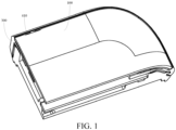
FIG. 1 is a schematic partial diagram of an electronic device according to an embodiment of this application; -
FIG. 2 is a schematic partial enlarged diagram ofFIG. 1 ; -
FIG. 3 is a sectional view of an electronic device according to an embodiment of this application; and -
FIG. 4 is a schematic exploded view of an electronic device according to an embodiment of this application. -
- 100-Cover plate, 110-Second notch;
- 200-Second sealing member, 210-First through hole;
- 300-Middle frame, 310-Body portion, 320-Connecting portion, 330-Second through hole, 340-Mounting groove, 350-Counterbore;
- 410-First channel, 420-Second channel;
- 500-Microphone;
- 610-Support, 611-Groove, 612-Convex portion, 613-Threaded hole, 614-First portion, 615-Second portion, 620-Circuit board, 621-First through hole, 622-Third through hole;
- 710-Third sealing member, 711-Fourth through hole, 720-Dustproof portion, 730-Second sealing member; and
- 800-Threaded connecting member.
- In order to make the objectives, technical solutions and advantages of this application clearer, the technical solutions of this application will be described clearly and completely in combination with specific embodiments of this application and corresponding accompanying drawings. Obviously, the described embodiments are only part of the embodiments of this application and not the whole embodiments. All other embodiments obtained by a person of ordinary skill in the art based on the embodiments of this application without creative efforts shall fall within the protection scope of this application.
- The terms "first", "second" and the like in the description and claims of the application are configured to distinguish similar objects, not to describe a specific order or precedence. It should be understood that the data in such a way are interchangeable in proper circumstances, so that the embodiments of this application can be implemented in other orders than the order illustrated or described herein. Objects distinguished by "first", "second", and the like are usually one type, and the quantity of objects is not limited. For example, there may be one or more first objects. In addition, in the specification and the claims, "and/or" means at least one of the connected objects, and the character "/" generally indicates an "or" relationship between the associated objects.
- The technical solutions disclosed in the embodiments of this application are described in detail below through specific embodiments and application scenarios thereof with reference to the accompanying drawings.
- Referring to
FIG. 1 to FIG. 4 , an embodiment of this application discloses an electronic device, including acover plate 100, acircuit board 620, amiddle frame 300, and amicrophone 500. - The
cover plate 100 may be a rear cover, thecircuit board 620 may be a main board of the electronic device, and thecircuit board 620 is provided with a first throughhole 621. Themiddle frame 300 is a basic component of the electronic device, and themiddle frame 300 can provide a mounting basis for other components of the electronic device. In this embodiment of this application, themiddle frame 300 includes abody portion 310 for forming a sidewall of the electronic device and a connectingportion 320 extending from thebody portion 310 into the electronic device, where the connectingportion 320 is in contact with a side of thecircuit board 620 facing away from themicrophone 500, the connectingportion 320 is provided with a second throughhole 330, the second throughhole 330 faces the first throughhole 621, thecover plate 100 and the connectingportion 320 overlap, afirst channel 410 is arranged between thecover plate 100 and thebody portion 310, asecond channel 420 is arranged between the cover plate and the connectingportion 320, and the first throughhole 621, the second throughhole 330, thesecond channel 420, and thefirst channel 410 are in communication and form a sound guide channel. - Optionally, the cover plate may also be a screen cover plate, and the screen cover plate may be an OLED screen cover plate or an LCD screen cover plate.
- It is not easy for a user to see the sound guide channel, which makes high appearance integrity and consistency of the electronic device. One port of the
first channel 410 is exposed on an external surface of the electronic device, that is, thefirst channel 410 is in communication with an external part of the electronic device, and thefirst channel 410 may be used for sound guide of the electronic device. Specifically, thefirst channel 410 may be in an elongated strip shape, which can reduce a width of thefirst channel 410, thereby making thefirst channel 410 more hidden. An extension direction of thefirst channel 410 is a length direction of thefirst channel 410. In this case, an area of thefirst channel 410 can be increased by increasing a length of thefirst channel 410, to meet the sound guide requirement of themicrophone 500. Specifically, the shape and structure of thefirst channel 410 may be determined by the shape and structure of thecover plate 100 and themiddle frame 300. - In the electronic device disclosed in this embodiment of this application, the
middle frame 300 includes abody portion 310 for forming a sidewall of the electronic device and a connectingportion 320 extending from thebody portion 310 into the electronic device, where the connectingportion 320 is in contact with a side of thecircuit board 620 facing away from themicrophone 500, the connectingportion 320 is provided with a second throughhole 330, the second throughhole 330 faces the first throughhole 621, thecover plate 100 and the connectingportion 320 overlap, afirst channel 410 is arranged between thecover plate 100 and thebody portion 310, asecond channel 420 is arranged between the cover plate and the connectingportion 320, and the first throughhole 621, the second throughhole 330, thesecond channel 420, and thefirst channel 410 are in communication and form a sound guide channel. In this case, the first channel between thecover plate 100 and themiddle frame 300 can be used to transmit sound, so that there is no need to provide a sound guide hole on themiddle frame 300, reducing the quantity of holes on themiddle frame 300, thereby improving the integrity and appearance consistency of themiddle frame 300, promoting the appearance consistency of the electronic device, and improving user experience. In addition, thefirst channel 410 is narrower than the sound guide hole, so that moisture or dust in the environment can be effectively prevented from entering the electronic device, thereby improving the waterproof and dustproof performance of the electronic device, and improving the reliability of the electronic device. - In addition, the first channel between the
cover plate 100 and themiddle frame 300 is used to transmit sound information, and there is no need to process a sound guide hole on themiddle frame 300 additionally, thereby optimizing the processing process of themiddle frame 300, so that the processing steps of themiddle frame 300 are simplified, thereby improving the manufacturability of themiddle frame 300, and reducing the manufacturing cost of the electronic device. - As described above, the
cover plate 100 and the connectingportion 320 overlap. In order to prevent external impurities (such as dust and moisture) from entering the electronic device through a gap between thecover plate 100 and the connectingportion 320, optionally, the electronic device may further include afirst sealing member 200, and thefirst sealing member 200 is arranged between thecover plate 100 and the connectingportion 320; and thesecond channel 420 is arranged between thecover plate 100, the connectingportion 320, and thefirst sealing member 200. Thefirst sealing member 200 can block dust and moisture from entering the electronic device to a large extent, thereby preventing themicrophone 500 from being easily eroded by dust or moisture, to protect themicrophone 500, and prevent dust or moisture from corroding the electronic components inside the electronic device, thereby further improving the reliability of the electronic device. - In order to further improve the hidden nature of the
first channel 410, so that thefirst channel 410 is more difficult to be found, optionally, the connectingportion 320 may be provided with a mountinggroove 340, at least a portion of thecover plate 100 is arranged in the mountinggroove 340, the second throughhole 330 is provided at a bottom of the mountinggroove 340, and thefirst sealing member 200, thecover plate 100, and the mounting groove form thesecond channel 420. In this case, thecover plate 100 and an inner sidewall of the mountinggroove 340 can form thefirst channel 410. Compared with thecover plate 100 being arranged on the connectingportion 320 without the mountinggroove 340, thefirst channel 410 is more easily formed in this arrangement mode. Since thecover plate 100 and the inner sidewall of the mountinggroove 340 form thefirst channel 410, which makes thefirst channel 410 more hidden, it is more difficult for the user to find thefirst channel 410, thereby making higher appearance integrity and consistency of the electronic device. In addition, at least a portion of thecover plate 100 is arranged in the mountinggroove 340, which can reduce a thickness of the electronic device and facilitate the lightweight development of the electronic device. - Optionally, the
first sealing member 200 may be provided with a first throughhole 210, and the first throughhole 210 is in communication with the second channel, that is, a bore diameter of the first through hole is greater than or equal to a length of the second channel. This method is simple, reliable, and easy to operate, which is conducive to reducing the sound leakage of the electronic device. - The
cover plate 100 may be clamped to themiddle frame 300 or in threaded connection to themiddle frame 300. Optionally, thefirst sealing member 200 may include a foam adhesive layer, and thecover plate 100 may be bonded to the connectingportion 320 through the foam adhesive layer. The bonding method is simple and easy to operate, and the bondedcover plate 100 and connectingportion 320 are in reliable connection. In addition, the foam adhesive layer can make better sealing of thesecond channel 420, prevent sound transmission from the gap between thecover plate 100 and the connectingportion 320, and avoid large sound loss, so that more sound can be transmitted through thefirst channel 410, to avoid the sound leakage of the electronic device, and avoid weak sound picked up by themicrophone 500, thereby making better sound characteristics of the electronic device. - In an optional embodiment, an edge of a side at which the
cover plate 100 fits thebody portion 310 may be provided with asecond notch 110, and thesecond notch 110 forms thefirst channel 410. Part of the material is removed from the edge of the side at which thecover plate 100 fits thebody portion 310, so that thefirst channel 410 between thecover plate 100 and thebody portion 310 is larger, thereby increasing the area of thefirst channel 410, so that thefirst channel 410 can transmit more sound, thereby further improving the sound characteristics of the electronic device. - Certainly, alternatively, the edge of the side at which the
body portion 310 fits thecover plate 100 may be provided with a third notch, and the third notch forms thefirst channel 410. This solution can also increase the area of thefirst channel 410, so that thefirst channel 410 can transmit more sound, thereby further improving the sound characteristics of the electronic device. Optionally, thesecond notch 110 and the third notch may be in an elongated strip shape, or certainly, in other shapes. This is not limited in this embodiment of this application. - In an optional embodiment, the electronic device may further include a
support 610, thesupport 610 has afirst portion 614 and asecond portion 615 that are connected to each other, thefirst portion 614 abuts against the connectingportion 320, thesecond portion 615 is arranged at a side of thecircuit board 620 with themicrophone 500, thesecond portion 615 is provided with agroove 611, and at least a portion of themicrophone 500 is arranged in thegroove 611. Thegroove 611 and thecircuit board 620 may form an accommodation space, themicrophone 500 is electrically connected to thecircuit board 620 and may be located in the accommodation space, thecircuit board 620 is located between thesecond portion 615 and themiddle frame 300, and thecircuit board 620 is provided with a first throughhole 621, so that the accommodation space may be in communication with the second throughhole 310 through the first throughhole 621. The accommodation space can provide an independent sound cavity for themicrophone 500, so that themicrophone 500 can work well. For example, the accommodation space can also protect themicrophone 500, and prevent themicrophone 500 from being easily eroded by dust or moisture, thereby improving the reliability of themicrophone 500. - In order to prevent dust or moisture from entering the electronic device, in an optional embodiment, the electronic device may further include a
second sealing member 730, and thefirst portion 614 abuts against the connectingportion 320 through thesecond sealing member 730. Thesecond sealing member 730 can seal a gap between thefirst portion 614 and themiddle frame 300 to prevent dust or moisture from entering the electronic device through the gap between thefirst portion 614 and themiddle frame 300, thereby preventing dust and moisture from damaging the electronic components of the electronic device, further improving the reliability of the electronic device. Optionally, thesecond sealing member 730 may be made of a material such as silicone and rubber. - Specifically, the
support 610 may be an upper cover of the main board of the electronic device, that is, a screen support, or certainly a separate support for forming the accommodation space; and thecircuit board 620 may be a main board or a sub-board of the electronic device, or certainly a separate circuit board for arranging themicrophone 500 in the electronic device. Thesupport 610 and thecircuit board 620 are not limited in this embodiment of this application. - In order to further protect the
microphone 500, in an optional embodiment, athird sealing member 710 is arranged between themiddle frame 300 and thecircuit board 620, thethird sealing member 710 is provided with a fourth throughhole 711, the fourth throughhole 711 is opposite to the first throughhole 621, and the second throughhole 330 is in communication with the first throughhole 621 through the fourth throughhole 711. Thethird sealing member 710 can block dust and moisture from entering the accommodation space to a large extent, thereby preventing themicrophone 500 from being easily eroded by dust or moisture, further protecting themicrophone 500. In addition, the fourth throughhole 711 makes thethird sealing member 710 not affect the sound transmission, to ensure that the electronic device can make sound and pick up sound normally. Optionally, thethird sealing member 710 may be made of a material such as silicone and rubber. - Further, the
second portion 615, thecircuit board 620, and the connectingportion 320 may be fixedly connected through a threaded connectingmember 800. This connection method has high connection stability, which can make reliable connection between thesupport 610, thecircuit board 620, and themiddle frame 300, and avoid loosening of themiddle frame 300 from thecircuit board 620, thereby avoiding failure of the sealing effect of thethird sealing member 710, further improving the sealing reliability of thethird sealing member 710. The threaded connectingmember 800 may be a bolt or a screw. - Further, the
second portion 615 may be provided with aconvex portion 612, theconvex portion 612 can form a portion of a sidewall of thegroove 611, and the threaded connectingmember 800 may be connected to theconvex portion 612 to make a connection position of the threaded connectingmember 800 close to thethird sealing member 710, so that themiddle frame 300 close to thethird sealing member 710 can be locked to thecircuit board 620 to further improve the sealing reliability of thethird sealing member 710. The connection position of the threaded connectingmember 800 is close to thethird sealing member 710, that is, a distance between the threaded connectingmember 800 and thethird sealing member 710 cannot exceed a preset distance. The preset distance may be 1 cm or 1.5 cm. The preset distance may be determined according to a size of the electronic device and a specific structure of themiddle frame 300. The preset distance is not specifically limited in this embodiment of this application. - Specifically, the
middle frame 300 may be provided with acounterbore 350, thecircuit board 620 may be provided with a third throughhole 622, theconvex portion 612 may be provided with a threadedhole 613, one end of the threaded connectingmember 800 passes through thecounterbore 350 and the third throughhole 622 to be in thread fit with the threadedhole 613, and another end of the threaded connectingmember 800 is pressed in thecounterbore 350. In this case, the threaded connectingmember 800 is difficult to affect the stacking of other components inside the electronic device, which is convenient for the staff to arrange, and the threaded connectingmember 800 does not increase the thickness of the electronic device. - In an optional embodiment, a
dustproof portion 720 is arranged between the second throughhole 330 and the fourth throughhole 711 to prevent dust from entering the accommodation space through the sound guide channel of themicrophone 500, thereby preventing themicrophone 500 from being easily eroded by dust or moisture, further improving the reliability of themicrophone 500. It should be noted that, the first throughhole 621, the second throughhole 330, thesecond channel 420, and thefirst channel 410 are in communication and form the sound guide channel of themicrophone 500. In addition, thedustproof portion 720 may be sandwiched between thethird sealing member 710 and themiddle frame 300, so that there is no need to arrange components for mounting thedustproof portion 720 on themiddle frame 300, thereby making a simple and convenient mounting operation of thedustproof portion 720. Thedustproof portion 720 may be a dustproof net. - The electronic device disclosed in the embodiments of this application can be an intelligent mobile phone, a tablet computer, an e-book reader, a wearable device (such as a smart watch), an electronic game console and other devices, and the embodiments of this application do not limit specific types of the electronic device.
- In the above embodiments of the application, the differences between embodiments are mainly described. As long as the different optimization features between embodiments are not contradictory, they can be combined to form better embodiments. Considering the conciseness of the writing, no repeated description is provided.
- The above are only embodiments of this application and are not intended to limit this application. For a person skilled in the art, various modifications and changes can be made to the present application. Any modification, equivalent replacement, or improvement made application spirit and principle of the present application shall fall within the scope of the claims of the present application.
Claims (11)
- An electronic device, comprising:a cover plate;a circuit board, provided with a first through hole;a microphone, arranged on the circuit board, wherein a sound pickup hole of the microphone faces the first through hole; anda middle frame, comprising a body portion for forming a sidewall of the electronic device and a connecting portion extending from the body portion into the electronic device, wherein the connecting portion is in contact with a side of the circuit board facing away from the microphone, the connecting portion is provided with a second through hole, the second through hole, the cover plate, and the connecting portion overlap, a first channel is arranged between the cover plate and the body portion, and a second channel is arranged between the cover plate and the connecting portion; andthe first through hole, the second through hole, the second channel, and the first channel are in communication and form a sound guide channel.
- The electronic device according to claim 1, wherein the electronic device further comprises a first sealing member, and the first sealing member is arranged between the cover plate and the connecting portion; and the second channel is arranged between the cover plate, the connecting portion, and the first sealing member.
- The electronic device according to claim 2, wherein the connecting portion is provided with a mounting groove, at least a portion of the cover plate is arranged in the mounting groove, the second through hole is provided at a bottom of the mounting groove, and the first sealing member, the cover plate, and the mounting groove form the second channel.
- The electronic device according to claim 2, wherein the first sealing member comprises a foam adhesive layer, and the cover plate is bonded to the connecting portion through the foam adhesive layer.
- The electronic device according to claim 1, wherein the electronic device further comprises a support, the support has a first portion and a second portion that are connected to each other, the first portion abuts against the connecting portion, the second portion is arranged at a side of the circuit board with the microphone, the second portion is provided with a groove, and at least a portion of the microphone is arranged in the groove.
- The electronic device according to claim 5, wherein the electronic device further comprises a second sealing member, and the first portion abuts against the connecting portion through the second sealing member.
- The electronic device according to claim 5, wherein the second portion, the circuit board, and the connecting portion are connected through a threaded connecting member.
- The electronic device according to claim 7, wherein the second portion is provided with a convex portion, the convex portion forms a portion of a sidewall of the groove, and the threaded connecting member is connected to the convex portion.
- The electronic device according to claim 8, wherein the middle frame is provided with a counterbore, the circuit board is provided with a third through hole, the convex portion is provided with a threaded hole, one end of the threaded connecting member passes through the counterbore and the third through hole to be in thread fit with the threaded hole, and another end of the threaded connecting member is pressed in the counterbore.
- The electronic device according to any one of claims 5 to 9, wherein a third sealing member is arranged between the middle frame and the circuit board, the third sealing member is provided with a fourth through hole, the fourth through hole is opposite to the first through hole, and the second through hole is in communication with the first through hole through the fourth through hole.
- The electronic device according to claim 10, wherein a dustproof portion is arranged between the second through hole and the fourth through hole.
Applications Claiming Priority (2)
| Application Number | Priority Date | Filing Date | Title |
|---|---|---|---|
| CN202011175792.8A CN112291391B (en) | 2020-10-28 | 2020-10-28 | Electronic equipment |
| PCT/CN2021/126020 WO2022089347A1 (en) | 2020-10-28 | 2021-10-25 | Electronic device |
Publications (3)
| Publication Number | Publication Date |
|---|---|
| EP4221250A1 true EP4221250A1 (en) | 2023-08-02 |
| EP4221250A4 EP4221250A4 (en) | 2024-03-13 |
| EP4221250B1 EP4221250B1 (en) | 2026-02-11 |
Family
ID=74372619
Family Applications (1)
| Application Number | Title | Priority Date | Filing Date |
|---|---|---|---|
| EP21885074.1A Active EP4221250B1 (en) | 2020-10-28 | 2021-10-25 | Electronic device |
Country Status (6)
| Country | Link |
|---|---|
| US (1) | US12549215B2 (en) |
| EP (1) | EP4221250B1 (en) |
| KR (1) | KR102779644B1 (en) |
| CN (1) | CN112291391B (en) |
| ES (1) | ES3064119T3 (en) |
| WO (1) | WO2022089347A1 (en) |
Families Citing this family (15)
| Publication number | Priority date | Publication date | Assignee | Title |
|---|---|---|---|---|
| CN112291391B (en) | 2020-10-28 | 2022-09-23 | 维沃移动通信有限公司 | Electronic equipment |
| US12309305B2 (en) * | 2021-01-11 | 2025-05-20 | Samsung Electronics Co., Ltd. | Electronic device including waterproof structure |
| DE112021007009T5 (en) * | 2021-03-03 | 2023-12-21 | Lg Electronics Inc. | MOBILE DEVICE |
| CN116075045B (en) * | 2021-10-29 | 2025-04-04 | 华为终端有限公司 | Electronic devices |
| CN114520845B (en) * | 2022-04-14 | 2022-10-11 | 北京荣耀终端有限公司 | terminal device |
| CN115103247B (en) * | 2022-07-25 | 2023-01-13 | 荣耀终端有限公司 | Shell assembly and electronic equipment |
| CN119094639A (en) * | 2022-08-24 | 2024-12-06 | 荣耀终端有限公司 | Portable electronic devices |
| CN119676350A (en) * | 2022-08-24 | 2025-03-21 | 荣耀终端股份有限公司 | Middle frame assembly and electronic device including the same |
| CN116085365A (en) * | 2022-12-28 | 2023-05-09 | 东莞华贝电子科技有限公司 | Screw fixing structure and electronic equipment |
| WO2025033668A1 (en) * | 2023-08-07 | 2025-02-13 | 삼성전자 주식회사 | Electronic device comprising conductive pattern and adhesive member |
| CN120301958A (en) * | 2024-01-04 | 2025-07-11 | 荣耀终端股份有限公司 | Electronic devices |
| WO2025184879A1 (en) * | 2024-03-07 | 2025-09-12 | 荣耀终端股份有限公司 | Electronic device |
| CN222602435U (en) * | 2024-03-30 | 2025-03-11 | 荣耀终端股份有限公司 | An electronic device |
| CN118382052A (en) * | 2024-04-19 | 2024-07-23 | 维沃移动通信有限公司 | Airtightness testing method for electronic equipment and microphones |
| CN120980384A (en) * | 2024-05-08 | 2025-11-18 | 荣耀终端股份有限公司 | electronic devices |
Family Cites Families (18)
| Publication number | Priority date | Publication date | Assignee | Title |
|---|---|---|---|---|
| US9101279B2 (en) | 2006-02-15 | 2015-08-11 | Virtual Video Reality By Ritchey, Llc | Mobile user borne brain activity data and surrounding environment data correlation system |
| KR101900282B1 (en) * | 2012-10-22 | 2018-09-19 | 삼성전자주식회사 | Microphone for electronic device |
| KR20150005119A (en) | 2013-07-04 | 2015-01-14 | 삼성전자주식회사 | Electronic device with microphone device |
| CN204795204U (en) | 2015-05-27 | 2015-11-18 | 上海与德通讯技术有限公司 | Mobile terminal's speaker structure |
| KR102312125B1 (en) * | 2017-07-03 | 2021-10-12 | 엘지디스플레이 주식회사 | Display apparatus |
| CN108307285A (en) * | 2017-12-12 | 2018-07-20 | 努比亚技术有限公司 | Mike's seal assembly and mobile terminal and its assembly method for mobile terminal |
| KR102468959B1 (en) * | 2018-04-17 | 2022-11-23 | 삼성전자 주식회사 | Conduit of electronic device and the electronic device comprising the same |
| CN109167863B (en) * | 2018-08-10 | 2021-02-09 | 瑞声科技(新加坡)有限公司 | Receiver module |
| CN108924320B (en) * | 2018-08-31 | 2020-06-23 | 维沃移动通信有限公司 | Mobile terminal |
| CN109413246B (en) * | 2018-10-24 | 2021-03-23 | Oppo(重庆)智能科技有限公司 | Shell assembly and electronic equipment |
| CN210137344U (en) * | 2019-08-26 | 2020-03-10 | Oppo广东移动通信有限公司 | an electronic device |
| CN210137422U (en) * | 2019-09-29 | 2020-03-10 | Oppo广东移动通信有限公司 | Electronic equipment |
| CN210137348U (en) * | 2019-09-29 | 2020-03-10 | Oppo广东移动通信有限公司 | Electronic equipment |
| CN210518454U (en) * | 2019-12-03 | 2020-05-12 | 无锡闻泰信息技术有限公司 | Microphone sound cavity sealing structure of terminal equipment and terminal equipment |
| CN210469407U (en) * | 2019-12-04 | 2020-05-05 | 维沃移动通信有限公司 | an electronic device |
| CN210469408U (en) * | 2019-12-04 | 2020-05-05 | 维沃移动通信有限公司 | an electronic device |
| CN111405413A (en) * | 2020-03-27 | 2020-07-10 | 维沃移动通信有限公司 | Electronic device |
| CN112291391B (en) * | 2020-10-28 | 2022-09-23 | 维沃移动通信有限公司 | Electronic equipment |
-
2020
- 2020-10-28 CN CN202011175792.8A patent/CN112291391B/en active Active
-
2021
- 2021-10-25 WO PCT/CN2021/126020 patent/WO2022089347A1/en not_active Ceased
- 2021-10-25 ES ES21885074T patent/ES3064119T3/en active Active
- 2021-10-25 EP EP21885074.1A patent/EP4221250B1/en active Active
- 2021-10-25 KR KR1020237014987A patent/KR102779644B1/en active Active
-
2023
- 2023-04-21 US US18/137,618 patent/US12549215B2/en active Active
Also Published As
| Publication number | Publication date |
|---|---|
| KR102779644B1 (en) | 2025-03-12 |
| EP4221250A4 (en) | 2024-03-13 |
| KR20230079431A (en) | 2023-06-07 |
| EP4221250B1 (en) | 2026-02-11 |
| WO2022089347A1 (en) | 2022-05-05 |
| CN112291391B (en) | 2022-09-23 |
| ES3064119T3 (en) | 2026-04-22 |
| US12549215B2 (en) | 2026-02-10 |
| US20230261684A1 (en) | 2023-08-17 |
| CN112291391A (en) | 2021-01-29 |
Similar Documents
| Publication | Publication Date | Title |
|---|---|---|
| US12549215B2 (en) | Electronic device with microphone housing structure | |
| CN108600421B (en) | Electronic device and method for manufacturing the same | |
| EP3605387A1 (en) | Optical fingerprint recognition assembly, display apparatus and mobile terminal | |
| WO2021190199A1 (en) | Electronic apparatus | |
| WO2021190198A1 (en) | Electronic device | |
| KR20200100294A (en) | Electronic device with waterproof structure of sensor key assembly | |
| CN109151122B (en) | Display screen assembly, electronic equipment and assembling method of display screen assembly | |
| US12316794B2 (en) | Electronic device | |
| CN109413246B (en) | Shell assembly and electronic equipment | |
| KR101109313B1 (en) | Display device including touch screen panel | |
| CN108924320B (en) | Mobile terminal | |
| US11018204B1 (en) | Display panel and display device | |
| KR20190139653A (en) | Connector for connecting conductive frame to circuit board and electronic device therewith | |
| CN108922407B (en) | Display screens and display devices | |
| US20150077655A1 (en) | Electronic device without front case frame | |
| WO2020135170A1 (en) | Terminal device | |
| CN209390119U (en) | Display components and electronic equipment | |
| WO2021017829A1 (en) | Screen assembly and terminal device | |
| CN211928483U (en) | Electronic device | |
| CN108881540A (en) | Display screen component and electronic equipment | |
| CN113099006A (en) | Electronic device | |
| CN105828591A (en) | Mobile terminal | |
| CN108683750A (en) | Electronic device and manufacturing method thereof | |
| CN208954543U (en) | Displays and Display Devices | |
| WO2023039970A1 (en) | Controller |
Legal Events
| Date | Code | Title | Description |
|---|---|---|---|
| STAA | Information on the status of an ep patent application or granted ep patent |
Free format text: STATUS: THE INTERNATIONAL PUBLICATION HAS BEEN MADE |
|
| PUAI | Public reference made under article 153(3) epc to a published international application that has entered the european phase |
Free format text: ORIGINAL CODE: 0009012 |
|
| STAA | Information on the status of an ep patent application or granted ep patent |
Free format text: STATUS: REQUEST FOR EXAMINATION WAS MADE |
|
| 17P | Request for examination filed |
Effective date: 20230427 |
|
| AK | Designated contracting states |
Kind code of ref document: A1 Designated state(s): AL AT BE BG CH CY CZ DE DK EE ES FI FR GB GR HR HU IE IS IT LI LT LU LV MC MK MT NL NO PL PT RO RS SE SI SK SM TR |
|
| DAV | Request for validation of the european patent (deleted) | ||
| DAX | Request for extension of the european patent (deleted) | ||
| A4 | Supplementary search report drawn up and despatched |
Effective date: 20240213 |
|
| RIC1 | Information provided on ipc code assigned before grant |
Ipc: H04M 1/02 20060101ALI20240207BHEP Ipc: H04R 1/08 20060101AFI20240207BHEP |
|
| GRAP | Despatch of communication of intention to grant a patent |
Free format text: ORIGINAL CODE: EPIDOSNIGR1 |
|
| STAA | Information on the status of an ep patent application or granted ep patent |
Free format text: STATUS: GRANT OF PATENT IS INTENDED |
|
| INTG | Intention to grant announced |
Effective date: 20251203 |
|
| GRAS | Grant fee paid |
Free format text: ORIGINAL CODE: EPIDOSNIGR3 |
|
| GRAA | (expected) grant |
Free format text: ORIGINAL CODE: 0009210 |
|
| STAA | Information on the status of an ep patent application or granted ep patent |
Free format text: STATUS: THE PATENT HAS BEEN GRANTED |
|
| AK | Designated contracting states |
Kind code of ref document: B1 Designated state(s): AL AT BE BG CH CY CZ DE DK EE ES FI FR GB GR HR HU IE IS IT LI LT LU LV MC MK MT NL NO PL PT RO RS SE SI SK SM TR |
|
| REG | Reference to a national code |
Ref country code: CH Ref legal event code: F10 Free format text: ST27 STATUS EVENT CODE: U-0-0-F10-F00 (AS PROVIDED BY THE NATIONAL OFFICE) Effective date: 20260211 Ref country code: GB Ref legal event code: FG4D |
|
| REG | Reference to a national code |
Ref country code: DE Ref legal event code: R096 Ref document number: 602021047929 Country of ref document: DE |
|
| REG | Reference to a national code |
Ref country code: IE Ref legal event code: FG4D |
|
| REG | Reference to a national code |
Ref country code: NL Ref legal event code: FP |
|
| REG | Reference to a national code |
Ref country code: ES Ref legal event code: FG2A Ref document number: 3064119 Country of ref document: ES Kind code of ref document: T3 Effective date: 20260422 |