EP4220833A1 - Battery box, battery, support, and electrical device - Google Patents
Battery box, battery, support, and electrical device Download PDFInfo
- Publication number
- EP4220833A1 EP4220833A1 EP21954626.4A EP21954626A EP4220833A1 EP 4220833 A1 EP4220833 A1 EP 4220833A1 EP 21954626 A EP21954626 A EP 21954626A EP 4220833 A1 EP4220833 A1 EP 4220833A1
- Authority
- EP
- European Patent Office
- Prior art keywords
- box
- limit
- electrical apparatus
- battery
- limit member
- Prior art date
- Legal status (The legal status is an assumption and is not a legal conclusion. Google has not performed a legal analysis and makes no representation as to the accuracy of the status listed.)
- Pending
Links
Images







Classifications
-
- H—ELECTRICITY
- H01—ELECTRIC ELEMENTS
- H01M—PROCESSES OR MEANS, e.g. BATTERIES, FOR THE DIRECT CONVERSION OF CHEMICAL ENERGY INTO ELECTRICAL ENERGY
- H01M50/00—Constructional details or processes of manufacture of the non-active parts of electrochemical cells other than fuel cells, e.g. hybrid cells
- H01M50/20—Mountings; Secondary casings or frames; Racks, modules or packs; Suspension devices; Shock absorbers; Transport or carrying devices; Holders
- H01M50/233—Mountings; Secondary casings or frames; Racks, modules or packs; Suspension devices; Shock absorbers; Transport or carrying devices; Holders characterised by physical properties of casings or racks, e.g. dimensions
- H01M50/242—Mountings; Secondary casings or frames; Racks, modules or packs; Suspension devices; Shock absorbers; Transport or carrying devices; Holders characterised by physical properties of casings or racks, e.g. dimensions adapted for protecting batteries against vibrations, collision impact or swelling
-
- B—PERFORMING OPERATIONS; TRANSPORTING
- B60—VEHICLES IN GENERAL
- B60K—ARRANGEMENT OR MOUNTING OF PROPULSION UNITS OR OF TRANSMISSIONS IN VEHICLES; ARRANGEMENT OR MOUNTING OF PLURAL DIVERSE PRIME-MOVERS IN VEHICLES; AUXILIARY DRIVES FOR VEHICLES; INSTRUMENTATION OR DASHBOARDS FOR VEHICLES; ARRANGEMENTS IN CONNECTION WITH COOLING, AIR INTAKE, GAS EXHAUST OR FUEL SUPPLY OF PROPULSION UNITS IN VEHICLES
- B60K1/00—Arrangement or mounting of electrical propulsion units
- B60K1/04—Arrangement or mounting of electrical propulsion units of the electric storage means for propulsion
-
- H—ELECTRICITY
- H01—ELECTRIC ELEMENTS
- H01M—PROCESSES OR MEANS, e.g. BATTERIES, FOR THE DIRECT CONVERSION OF CHEMICAL ENERGY INTO ELECTRICAL ENERGY
- H01M50/00—Constructional details or processes of manufacture of the non-active parts of electrochemical cells other than fuel cells, e.g. hybrid cells
- H01M50/20—Mountings; Secondary casings or frames; Racks, modules or packs; Suspension devices; Shock absorbers; Transport or carrying devices; Holders
- H01M50/202—Casings or frames around the primary casing of a single cell or a single battery
-
- H—ELECTRICITY
- H01—ELECTRIC ELEMENTS
- H01M—PROCESSES OR MEANS, e.g. BATTERIES, FOR THE DIRECT CONVERSION OF CHEMICAL ENERGY INTO ELECTRICAL ENERGY
- H01M50/00—Constructional details or processes of manufacture of the non-active parts of electrochemical cells other than fuel cells, e.g. hybrid cells
- H01M50/20—Mountings; Secondary casings or frames; Racks, modules or packs; Suspension devices; Shock absorbers; Transport or carrying devices; Holders
- H01M50/204—Racks, modules or packs for multiple batteries or multiple cells
-
- H—ELECTRICITY
- H01—ELECTRIC ELEMENTS
- H01M—PROCESSES OR MEANS, e.g. BATTERIES, FOR THE DIRECT CONVERSION OF CHEMICAL ENERGY INTO ELECTRICAL ENERGY
- H01M50/00—Constructional details or processes of manufacture of the non-active parts of electrochemical cells other than fuel cells, e.g. hybrid cells
- H01M50/20—Mountings; Secondary casings or frames; Racks, modules or packs; Suspension devices; Shock absorbers; Transport or carrying devices; Holders
- H01M50/204—Racks, modules or packs for multiple batteries or multiple cells
- H01M50/207—Racks, modules or packs for multiple batteries or multiple cells characterised by their shape
- H01M50/209—Racks, modules or packs for multiple batteries or multiple cells characterised by their shape adapted for prismatic or rectangular cells
-
- H—ELECTRICITY
- H01—ELECTRIC ELEMENTS
- H01M—PROCESSES OR MEANS, e.g. BATTERIES, FOR THE DIRECT CONVERSION OF CHEMICAL ENERGY INTO ELECTRICAL ENERGY
- H01M50/00—Constructional details or processes of manufacture of the non-active parts of electrochemical cells other than fuel cells, e.g. hybrid cells
- H01M50/20—Mountings; Secondary casings or frames; Racks, modules or packs; Suspension devices; Shock absorbers; Transport or carrying devices; Holders
- H01M50/244—Secondary casings; Racks; Suspension devices; Carrying devices; Holders characterised by their mounting method
-
- H—ELECTRICITY
- H01—ELECTRIC ELEMENTS
- H01M—PROCESSES OR MEANS, e.g. BATTERIES, FOR THE DIRECT CONVERSION OF CHEMICAL ENERGY INTO ELECTRICAL ENERGY
- H01M50/00—Constructional details or processes of manufacture of the non-active parts of electrochemical cells other than fuel cells, e.g. hybrid cells
- H01M50/20—Mountings; Secondary casings or frames; Racks, modules or packs; Suspension devices; Shock absorbers; Transport or carrying devices; Holders
- H01M50/249—Mountings; Secondary casings or frames; Racks, modules or packs; Suspension devices; Shock absorbers; Transport or carrying devices; Holders specially adapted for aircraft or vehicles, e.g. cars or trains
-
- H—ELECTRICITY
- H01—ELECTRIC ELEMENTS
- H01M—PROCESSES OR MEANS, e.g. BATTERIES, FOR THE DIRECT CONVERSION OF CHEMICAL ENERGY INTO ELECTRICAL ENERGY
- H01M50/00—Constructional details or processes of manufacture of the non-active parts of electrochemical cells other than fuel cells, e.g. hybrid cells
- H01M50/20—Mountings; Secondary casings or frames; Racks, modules or packs; Suspension devices; Shock absorbers; Transport or carrying devices; Holders
- H01M50/262—Mountings; Secondary casings or frames; Racks, modules or packs; Suspension devices; Shock absorbers; Transport or carrying devices; Holders with fastening means, e.g. locks
-
- H—ELECTRICITY
- H01—ELECTRIC ELEMENTS
- H01M—PROCESSES OR MEANS, e.g. BATTERIES, FOR THE DIRECT CONVERSION OF CHEMICAL ENERGY INTO ELECTRICAL ENERGY
- H01M50/00—Constructional details or processes of manufacture of the non-active parts of electrochemical cells other than fuel cells, e.g. hybrid cells
- H01M50/20—Mountings; Secondary casings or frames; Racks, modules or packs; Suspension devices; Shock absorbers; Transport or carrying devices; Holders
- H01M50/262—Mountings; Secondary casings or frames; Racks, modules or packs; Suspension devices; Shock absorbers; Transport or carrying devices; Holders with fastening means, e.g. locks
- H01M50/264—Mountings; Secondary casings or frames; Racks, modules or packs; Suspension devices; Shock absorbers; Transport or carrying devices; Holders with fastening means, e.g. locks for cells or batteries, e.g. straps, tie rods or peripheral frames
-
- H—ELECTRICITY
- H01—ELECTRIC ELEMENTS
- H01M—PROCESSES OR MEANS, e.g. BATTERIES, FOR THE DIRECT CONVERSION OF CHEMICAL ENERGY INTO ELECTRICAL ENERGY
- H01M50/00—Constructional details or processes of manufacture of the non-active parts of electrochemical cells other than fuel cells, e.g. hybrid cells
- H01M50/20—Mountings; Secondary casings or frames; Racks, modules or packs; Suspension devices; Shock absorbers; Transport or carrying devices; Holders
- H01M50/271—Lids or covers for the racks or secondary casings
-
- H—ELECTRICITY
- H01—ELECTRIC ELEMENTS
- H01M—PROCESSES OR MEANS, e.g. BATTERIES, FOR THE DIRECT CONVERSION OF CHEMICAL ENERGY INTO ELECTRICAL ENERGY
- H01M50/00—Constructional details or processes of manufacture of the non-active parts of electrochemical cells other than fuel cells, e.g. hybrid cells
- H01M50/20—Mountings; Secondary casings or frames; Racks, modules or packs; Suspension devices; Shock absorbers; Transport or carrying devices; Holders
- H01M50/289—Mountings; Secondary casings or frames; Racks, modules or packs; Suspension devices; Shock absorbers; Transport or carrying devices; Holders characterised by spacing elements or positioning means within frames, racks or packs
-
- B—PERFORMING OPERATIONS; TRANSPORTING
- B60—VEHICLES IN GENERAL
- B60K—ARRANGEMENT OR MOUNTING OF PROPULSION UNITS OR OF TRANSMISSIONS IN VEHICLES; ARRANGEMENT OR MOUNTING OF PLURAL DIVERSE PRIME-MOVERS IN VEHICLES; AUXILIARY DRIVES FOR VEHICLES; INSTRUMENTATION OR DASHBOARDS FOR VEHICLES; ARRANGEMENTS IN CONNECTION WITH COOLING, AIR INTAKE, GAS EXHAUST OR FUEL SUPPLY OF PROPULSION UNITS IN VEHICLES
- B60K1/00—Arrangement or mounting of electrical propulsion units
- B60K1/04—Arrangement or mounting of electrical propulsion units of the electric storage means for propulsion
- B60K2001/0405—Arrangement or mounting of electrical propulsion units of the electric storage means for propulsion characterised by their position
- B60K2001/0438—Arrangement under the floor
-
- B—PERFORMING OPERATIONS; TRANSPORTING
- B60—VEHICLES IN GENERAL
- B60L—PROPULSION OF ELECTRICALLY-PROPELLED VEHICLES; SUPPLYING ELECTRIC POWER FOR AUXILIARY EQUIPMENT OF ELECTRICALLY-PROPELLED VEHICLES; ELECTRODYNAMIC BRAKE SYSTEMS FOR VEHICLES IN GENERAL; MAGNETIC SUSPENSION OR LEVITATION FOR VEHICLES; MONITORING OPERATING VARIABLES OF ELECTRICALLY-PROPELLED VEHICLES; ELECTRIC SAFETY DEVICES FOR ELECTRICALLY-PROPELLED VEHICLES
- B60L50/00—Electric propulsion with power supplied within the vehicle
- B60L50/50—Electric propulsion with power supplied within the vehicle using propulsion power supplied by batteries or fuel cells
- B60L50/60—Electric propulsion with power supplied within the vehicle using propulsion power supplied by batteries or fuel cells using power supplied by batteries
-
- H—ELECTRICITY
- H01—ELECTRIC ELEMENTS
- H01M—PROCESSES OR MEANS, e.g. BATTERIES, FOR THE DIRECT CONVERSION OF CHEMICAL ENERGY INTO ELECTRICAL ENERGY
- H01M2220/00—Batteries for particular applications
- H01M2220/20—Batteries in motive systems, e.g. vehicle, ship, plane
-
- Y—GENERAL TAGGING OF NEW TECHNOLOGICAL DEVELOPMENTS; GENERAL TAGGING OF CROSS-SECTIONAL TECHNOLOGIES SPANNING OVER SEVERAL SECTIONS OF THE IPC; TECHNICAL SUBJECTS COVERED BY FORMER USPC CROSS-REFERENCE ART COLLECTIONS [XRACs] AND DIGESTS
- Y02—TECHNOLOGIES OR APPLICATIONS FOR MITIGATION OR ADAPTATION AGAINST CLIMATE CHANGE
- Y02E—REDUCTION OF GREENHOUSE GAS [GHG] EMISSIONS, RELATED TO ENERGY GENERATION, TRANSMISSION OR DISTRIBUTION
- Y02E60/00—Enabling technologies; Technologies with a potential or indirect contribution to GHG emissions mitigation
- Y02E60/10—Energy storage using batteries
Definitions
- Embodiments of the present application relate to the field of batteries, and more particularly, to a battery box, a battery, a holder, and an electrical apparatus.
- the present application provides a battery box, a battery, a holder, and an electrical apparatus, which can enhance installation stability of the battery.
- a battery box including a box body for accommodating a battery cell; a first position-limit member disposed on a side of a first wall of the box body away from the battery cell, wherein the first wall is perpendicular to a first direction, the first direction is parallel to a traveling direction of an electrical apparatus after the box is mounted on the electrical apparatus, and the first position-limit member is used to limit a relative displacement of the box in the first direction.
- the first position-limit member is disposed on the side of the first wall of the box body away from the battery cell, the first wall is perpendicular to the first direction, and the first direction is parallel to a traveling direction of the electrical apparatus after the box is mounted on the electrical apparatus, so that after the box is mounted on the electrical apparatus, the first position-limit member can generate an acting force in the first direction with the electrical apparatus, that is, the first position-limit member can generate an acting force with the electrical apparatus in the traveling direction of the electrical apparatus and the direction opposite to the traveling direction, so as to limit a relative displacement of the box in the traveling direction of the electrical apparatus and the direction opposite to the traveling direction and improve installation stability of the box in the traveling direction of the electrical apparatus and the direction opposite to the traveling direction, thereby reducing influence of the electrical apparatus in a traveling state on the battery and its box, and ensuring normal operations of the battery and the electrical apparatus where the battery is located.
- the box further includes a second position-limit member disposed on a side of the box away from the battery cell and used to limit a relative displacement of the box in a second direction, the second direction being parallel to the direction of gravity after the box is mounted on the electrical apparatus.
- the second position-limit member is disposed on the side of the box away from the battery cell, the second position-limit member can generate an acting force in the second direction with the electrical apparatus after the box is mounted on the electrical apparatus, that is, the second position-limit member can generate an acting force in the direction of gravity and the opposite direction of gravity with the electrical apparatus, so as to limit a relative displacement of the box in the direction of gravity and the opposite direction of gravity, thereby further improving the installation stability of the box in the electrical apparatus and ensuring normal operations of the battery and the electrical apparatus where the battery is located.
- the first position-limit member includes a first position-limit block and a buffer block, wherein the first position-limit block is disposed on the first wall and can move along the first direction, the buffer block is disposed between the first position-limit block and the first wall, and the buffer block is used to provide a buffer distance of the first position-limit block in the first direction.
- the first position-limit block when mounting the box on the electrical apparatus, can move toward the inside of the box along the first direction through the matching between the buffer block and the first position-limit block, and the first position-limit block can not bring too much installation resistance, facilitating installation of the box on the electrical apparatus. Further, after the box is mounted on the electrical apparatus, the first position-limit block compresses the buffer block, the buffer block is then in a compressed state to provide an elastic acting force to the first position-limit block, so that the first position-limit block is in closely press fit with the electrical apparatus in the first direction, thereby ensuring the installation stability of the box in the first direction, that is, ensuring the installation stability of the box in the travel direction and the opposite traveling direction of the electrical apparatus.
- the first position-limit member further includes a first fastener, wherein the first position-limit block is disposed on the first wall through the first fastener, and the first fastener is used to provide a buffer space for the first position-limit block and the buffer block in the first direction.
- the first position-limit block is disposed on the first wall of the box by the first fastener, and the buffer space is provided for the first position-limit block and the buffer block, so that the first position-limit block can generate a relative displacement in the first direction through the buffer block, thereby facilitating the installation of the box on the electrical apparatus and the installation stability of the box in the first direction.
- a first end of the first position-limit block is provided with a wedge angle, and the first end of the first position-limit block is an end of the first position-limit block facing toward the opposite direction of gravity.
- the first end with the wedge angle in the first position-limit block when mounting the box on the electrical apparatus facing toward the opposite direction of gravity, can be gradually moved in the opposite direction of gravity, and the first end can be used for guiding and positioning of the box when mounting the box in the electrical apparatus, so that the box can be mounted in the electrical apparatus more conveniently.
- the second position-limit member is an elastic position-limit block, and the elastic position-limit block is compressed to abut against the electrical apparatus after the box is mounted on the electrical apparatus.
- the second position-limit member is an elastic position-limit block
- the elastic position-limit block is compressed to abut against the electrical apparatus after the box is mounted on the electrical apparatus, so that there is an elastic force between the elastic position-limit block staying a compressed state and the electrical apparatus; moreover, the elastic position-limit block is in closely press fit with the electrical apparatus in the second direction, thereby ensuring the installation stability of the box in the second direction, that is, ensuring the installation stability of the box in the direction of gravity and the opposite direction of gravity of the electrical apparatus.
- a first end of the elastic position-limit block is provided with a chamfer structure, and the first end of the elastic position-limit block is an end of the elastic position-limit block facing toward the opposite direction of gravity.
- the first end of the elastic position-limit block facing toward the opposite direction of gravity is in contact with the electrical apparatus first, and acts on the electrical apparatus;
- the first end of the elastic position-limit block is provided with a chamfer structure, which can facilitate compressing the first end of the elastic position-limit block to the electrical apparatus;
- the chamfer structure can avoid a stress concentration, thereby prolonging service life of the elastic position-limit block.
- the chamfer structure can also beautify the elastic position-limit block.
- the first wall is provided with an accommodating area, the accommodating area being used for accommodating the first position-limit member.
- the first wall of the box is provided with the accommodating area for accommodating the first position-limit member; on the one hand, a mounting space of the first position-limit member can be saved, and on the other hand, the first position-limit member can also be protected by the accommodating area, and is prevented from being damaged by external influences, thereby prolonging service life of the first position-limit member in the box.
- the first wall includes an extending portion, the extending portion extending along the first direction and away from the battery cell, and being used for arrangement of the second position-limit member.
- the center of the first position-limit member and the center of the second position-limit member are located on a first plane, the first plane being parallel to the plane determined by the first direction and the second direction.
- the center of the first position-limit member and the center of the second position-limit member are both located on the first plane that is parallel to the plane determined by the first direction and the second direction.
- first position-limit member and the second position-limit member are adjacently arranged on the same first wall, the acting force between the first position-limit member and the second position-limit member and the electrical apparatus is more concentrated, so that the installation stability of the box body in the electrical apparatus can be further improved; moreover, the first position-limit member and the second position-limit member are adjacently arranged, which also facilitates the installation and maintenance of the first position-limit member and the second position-limit member.
- the box body includes a plurality of first position-limit members, the plurality of first position-limit members being distributed on two first walls of the box body that are parallel to each other.
- the plurality of first position-limit members are distributed on the two first walls, the first position-limit members on the two first walls of the box each can generate an acting force in the first direction with the electrical apparatus, so that the box can be clamped with the electrical apparatus in the first direction, to further limit the relative displacement of the box in the electrical apparatus along the first direction, thereby improving the installation stability of the box in the electrical apparatus.
- a plurality of first position-limit members are distributed at four corners of the box body.
- the plurality of first position-limit members provided in the box are distributed at the four corners of the box body to limit a relative displacement of the four corners of the box body in the electrical apparatus, thereby improving the installation stability of the box in electrical installations.
- a holder which is applied to an electrical apparatus, and includes a holder body for mounting of a battery box of the electrical apparatus, wherein the box is used for accommodating battery cells; a third position-limit member disposed on a side of a first beam of the holder body close to the box, wherein an extension direction of the first beam is perpendicular to a first direction, the first direction is parallel to a traveling direction of the electrical apparatus, the third position-limit member is used to limit a relative displacement of the box in the first direction.
- the third position-limit member is disposed on a side of the first beam of the holder body close to the battery box, the extension direction of the first beam is perpendicular to the first direction, and the first direction is parallel to the traveling direction of the electrical apparatus, so that after the box is mounted on the holder body of the electrical apparatus, the third position-limit member can generate an acting force in the first direction with the electrical apparatus, that is, the third position-limit member can generate an acting force with the electrical apparatus in the traveling direction of the electrical apparatus and the direction opposite to the traveling direction, so as to limit the relative displacement of the box in the traveling direction of the electrical apparatus and the direction opposite to the traveling direction and improve installation stability of the box in the traveling direction of the electrical apparatus and the direction opposite to the traveling direction, thereby reducing influence of the electrical apparatus in a traveling state on the battery and its box, and ensuring normal operations of the battery and the electrical apparatus where the battery is located.
- the holder further includes a fourth position-limit member disposed on the holder body and used to limit a relative displacement of the box in a second direction, the second direction being parallel to the direction of gravity.
- the fourth position-limit member is disposed on the holder body, the fourth position-limit member can generate an acting force with the electrical apparatus in the second direction, that is, the fourth position-limit member can generate an acting force in the direction of gravity and the opposite direction of gravity with the box, so as to limit the relative displacement of the box in the direction of gravity and the opposite direction of gravity, thereby further improving installation stability of the box in the electrical apparatus and ensuring normal operations of the battery and the electrical apparatus where the battery is located.
- the fourth position-limit member includes a recess structure, the recess structure having an opening facing toward the direction of gravity.
- the recess structure is used for accommodating the second position-limit member of the box, so as to limit the relative displacement of the box in the second direction.
- the recess structure can match with the second position-limit member in the battery box, and the recess structure can be used for accommodating the second position-limit member and is in closely press fit with the second position-limit member, so that the box and the holder body are clamped the second direction, improving the installation stability of the box in the direction of gravity and the opposite direction of gravity of the holder body.
- the third position-limit member includes a third position-limit block and a second fastener, wherein the second fastener is used to fix the third position-limit block to the first beam, and an end of the third position-limit block facing toward the direction of gravity is provided with a wedge angle.
- the end of the third limit block facing toward the opposite direction of gravity can be provided with the wedge angle, so that when mounting the box on the holder facing toward the opposite direction of gravity, the box can be moved step by step toward the opposite direction of gravity by the aid of the end of the third position-limit block that is provided with the wedge angle.
- the end provided with the wedge angle can be used for guiding and positioning the box when mounting the box to the holder so that the box can be mounted in the holder more conveniently.
- the center of the third position-limit member and the center of the fourth position-limit member are located on a first plane, the first plane being parallel to a plane determined by the first direction and the second direction.
- the center of the third position-limit member and the center of the fourth position-limit member are both located on the first plane that is parallel to the plane determined by the first direction and the second direction.
- the third position-limit member and the fourth position-limit member are adjacently arranged on the same first wall, an acting force between the third position-limit member and fourth position-limit member and the electrical apparatus is more concentrated, so that the installation stability of the box in the holder can be further improved; moreover, the third position-limit member and the fourth position-limit member are adjacently arranged, which also facilitates the installation and maintenance of the third position-limit member and the fourth position-limit member.
- the holder includes a plurality of third position-limit members, the plurality of first position-limit members being distributed on two first beams of the holder body that are parallel to each other.
- the plurality of third position-limit members are distributed on the at least two first beams, the third position-limit members on the at least two first beams of the holder body each can generate an acting force in the first direction with the box, so that the box can be clamped with the holder body in the first direction, to further limit the relative displacement of the box in the holder in the first direction, thereby improving the installation stability of the box in the electrical apparatus.
- the plurality of third position-limit members are distributed at four corners of a space for accommodating the box body in the holder body.
- the plurality of third position-limit members can be further distributed at the four corners of the space for accommodating the box in the holder body, so as to be correspondingly disposed at the four corners of the box to limit relative displacements of the four corners of the box in the holder, thereby comprehensively improving the installation stability of the box in the holder and the electrical apparatus where the box is located.
- a battery including a battery cell and the battery box in the first aspect or any possible embodiment of the first aspect, wherein the box is used for accommodating the battery cell.
- an electrical apparatus including the battery in the third aspect, and the holder in the second aspect or any possible embodiment of the second aspect, wherein the third position-limit block of the holder matches with the first position-limit member of the battery to limit a relative displacement of the battery in the first direction.
- a method for preparing a battery including providing a box cell; providing a box, the box including a box body for accommodating the battery cell; a first position-limit member disposed on a side of a first wall of the box body away from the battery cell, wherein the first wall is perpendicular to a first direction, the first direction is parallel to a traveling direction of an electrical apparatus after the box is mounted on the electrical apparatus, and the first position-limit member is used to limit a relative displacement of the box in the first direction; and accommodating the battery cell in the box.
- a device for preparing a battery box body including a first providing module for providing a battery cell; a second providing module for providing a box, the box including a box body for accommodating the battery cell; a first position-limit member disposed on a side of a first wall of the box body away from the battery cell, wherein the first wall is perpendicular to a first direction, the first direction is parallel to a traveling direction of an electrical apparatus after the box is mounted on the electrical apparatus, and the first position-limit member is used to limit a relative displacement of the box in the first direction; and a mounting module for accommodating the battery cell in the box.
- the first position-limit member is disposed on the side of the first wall of the box body away from the battery cell, the first wall is perpendicular to the first direction, and the first direction is parallel to a traveling direction of an electrical apparatus after the box is mounted on the electrical apparatus, so that after the box is mounted on the electrical apparatus, the first position-limit member can generate an acting force in the first direction x with the electrical apparatus, that is, the first position-limit member can generate an acting force with the electrical apparatus in the traveling direction of the electrical apparatus and the direction opposite to the traveling direction, so as to limit a relative displacement of the box in the traveling direction of the electrical apparatus and the direction opposite to the traveling direction and improve installation stability of the box in the traveling direction of the electrical apparatus and the direction opposite to the traveling direction, thereby reducing influence of the electrical apparatus staying in a traveling state on the battery and its box, and ensuring normal operations of the battery and the electrical apparatus where the battery is located.
- the term "and/or" is only an association relationship for describing associated objects, indicating that three relationships may exist.
- a and/or B may represent three situations: A exists alone, both A and B exist, and B exists alone.
- the character "/" in the present application generally means that the associated objects before and after it are in an "or" relationship.
- an embodiment means that a particular feature, structure, or characteristic described in connection with the embodiment can be included in at least one embodiment of the present application.
- the appearance of this phrase in various places in the specification does not necessarily refer to the same embodiment, nor is it a separate or alternative embodiment that is mutually exclusive with other embodiments. It is understood explicitly and implicitly by those skilled in the art that the embodiments described in the present application can be combined with other embodiments.
- a battery cell may include a lithium-ion secondary battery, a lithium-ion primary battery, a lithium-sulfur battery, a sodium/lithium-ion battery, a sodium-ion battery, or a magnesium-ion battery, etc., which is not limited in the examples of the present application.
- the battery cell may be cylindrical, flat, rectangular, or in other shapes, which is also not limited in the examples of the present application.
- the battery cells are generally divided into three types according to packaging manners: cylindrical battery cells, rectangular battery cells, and pouch cells, which are not limited in the examples of the present application.
- the battery mentioned in the examples of the present application refers to a single physical module including one or more battery cells to provide a higher voltage and capacity.
- the battery mentioned in the present application may include a battery module, a battery pack, or the like.
- the battery typically includes a box body for encapsulating one or more battery cells.
- the box body can prevent liquids or other foreign matters from affecting charging or discharging of the battery cells.
- a battery is generally mounted in an electrical apparatus to provide electrical energy for the electrical apparatus. If the battery is mounted in the electrical apparatus in an unstable manner and the stability is poor, when the electrical apparatus stays in a motion state, especially when it stays in a motion state with an acceleration, a specific external force is generated on the battery, causing the battery to have a relative displacement in the electrical apparatus or even be out of a fixed mounting position, thereby affecting an electrical connection between the battery and the electrical apparatus, and affecting performance of the battery. Eventually, it may lead to an abnormal operation of the electrical apparatus and bring certain safety hazards.
- the present application provides a battery box for accommodating a battery cell.
- the box includes a first position-limit member. After the box is mounted on the electrical apparatus, the first position-limit member is used to limit a relative displacement of the battery in a traveling direction of the electrical apparatus.
- the present application further provides a holder, which is applied to an electrical apparatus. The holder is used for mounting of a battery of the electrical apparatus.
- the holder includes a third position-limit member. After the battery box is mounted on the electrical apparatus, the third position-limit member can also be used to limit the relative displacement of the battery in the traveling direction of the electrical apparatus.
- the electrical apparatus is generally moved along its traveling direction, and may generate a motion with an acceleration, which has a greater impact on the battery.
- the installation stability of the battery in the electrical apparatus especially the installation stability in the traveling direction of the electrical apparatus can be enhanced, thereby ensuring normal operations of the battery and the electrical apparatus where the battery is located.
- the technical solutions described in the embodiments of the present application are all applicable to various electrical apparatuses using batteries, such as electric vehicles, electric toys, electric tools, ships, spacecrafts, and the like.
- the spacecrafts include airplanes, rockets, space shuttles, spaceships, etc.
- FIG. 1 is a schematic structural diagram of a vehicle 1 according to an embodiment of the present application.
- the vehicle 1 may be a fuel vehicle, a gas vehicle, or a new energy vehicle, and the new energy vehicle may be an all-electric vehicle, a hybrid electric vehicle, an extended range electric vehicle, or the like.
- the interior of vehicle 1 may be provided with a motor 14, a controller 13, and a battery 10, and controller 13 is configured to control the battery 10 to supply power to the motor 14.
- the battery 10 may be arranged at the bottom or the head or the tail of the vehicle 1.
- the battery 10 may be configured to supply power to the vehicle 1, for example, the battery 10 may be used as an operating power source of the vehicle 1, which is used for a circuit system of the vehicle 1, for example, for operation power requirements of the vehicle 1 during starting, navigation and running.
- the battery 10 can not only be used as the operating power source of vehicle 1, but also can be used as a driving power source of vehicle 1 to provide driving power for vehicle 1 instead of or partially instead of fuel or natural gas.
- the battery may include a plurality of battery cells.
- the plurality of battery cells may be in series connection, in parallel connection, or in parallel-series connection, and the parallel-series connection refers to mixing of the series connection and the parallel connection.
- the battery may also be called a battery pack.
- the plurality of battery cells may be in series connection, in parallel connection, or in parallel-series connection to form a battery module first, and a plurality of battery modules may then be in series connection, in parallel connection, or in parallel-series connection to form a battery. That is, the plurality of battery cells may directly form a battery, or form a battery module first, and then the battery module forms a battery.
- FIG. 2 is a schematic structural diagram of a battery 10 according to an embodiment of the present application, where the battery 10 may include a plurality of battery cells 100.
- the battery 10 may further include a box body 200 (or a cover body), the interior of the box body 200 is of a hollow structure, and the plurality of battery cells 100 are accommodated in the box body 200.
- the box body 200 may include two portions, which are referred to here as a first portion 2100 and a second portion 2200 respectively, the first portion 2100 and the second portion 2200 being engaged together.
- the shapes of the first portion 2100 and the second portion 2200 may be determined according to the combined shape of the plurality of battery cells 100, and the first portion 2100 and the second portion 2200 each have an opening.
- first portion 2100 and the second portion 2200 may each be a hollow cuboid with only one surface being an open surface, the opening of the first portion 2100 and the opening of the second portion 2200 are arranged opposite to each other, and the first portion 2100 and the second portion 2200 are mutually engaged to form box body 200 with a closed chamber.
- the plurality of battery cells 100 are in series connection or in parallel connection or in a parallel-series connection, they are placed in the box body 200 formed after the first portion 2100 and the second portion 2200 are engaged together.
- the battery 10 may further include other structures, which will not be repeated here.
- the battery 10 may further include a busbar component, and the busbar component is configured to realize an electrical connection between the plurality of battery cells 100, such as parallel connection or series connection or series-parallel connection.
- the busbar component may realize an electrical connection between the battery cells 100 by connecting electrode terminals of the battery cells 100.
- the busbar component may be fixed to the electrode terminals of the battery cells 100 by welding.
- the electrical energy of the plurality of battery cells 100 may further pass through the box by a conductive mechanism to be drawn out.
- the conductive mechanism may also belong to the busbar component.
- the number of battery cells 100 may be set to any value.
- the plurality of battery cells 100 may be in series connection, or in parallel connection, or in series-parallel connection to achieve a larger capacity or power. Since each battery 10 may include a large number of battery cells 100, in order to facilitate the installation, the battery cells 100 may be divided in groups, and each group of battery cells 100 constitutes a battery module.
- the number of battery cells 100 included in the battery module is not limited, and can be set according to needs.
- FIG. 3 shows a schematic structural diagram of a holder body 300 provided in the vehicle 1.
- the box body 200 of the battery 10 described above can be mounted on the holder body 300, so that the battery 10 is mounted in the vehicle 1.
- the holder body 300 may be disposed on a chassis of the vehicle 1 to facilitate the installation or replacement of the battery 10 that is disposed on the holder body 300.
- the holder body 300 may also be disposed at other positions of the battery 10, which is not limited in this embodiment of the present application.
- the holder body 300 may include a plurality of beams, and the plurality of beams surround to form an accommodating space to accommodate at least one of the batteries 10, specifically, to accommodate at least one box body 200 of the at least one of the batteries 10, so that the at least one battery 10 is mounted in the vehicle 1.
- the holder body 300 may include at least one first beam 301 and a pair of second beams 302, wherein the pair of second beams 302 are opposite to each other, and the at least one first beam 301 is perpendicular to an extension direction of the second beam 302, and is connected to the pair of second beams 302.
- the holder body 300 includes three first beams 301, wherein two first beams 301 are respectively connected to two ends of the pair of second beams 302, and the other first beam 301 is connected to the middle of the pair of second beams 302.
- Two symmetrical spaces, i.e., a first space 3100 and a second space 3200 can be formed between the three first beams 301 and the pair of second beams 302.
- the first space 3100 and the second space 3200 can be used for accommodating box bodies 200 of two batteries 10 respectively.
- the size of the first space 3100 and the second space 3200 may fit with the size of the box body 200, and thus may be designed correspondingly.
- the holder body 300 may also include other numbers of first beams 301.
- the holder body 300 only includes one first beam 301 that is connected to the middle of the pair of second beams 302.
- a space between the pair of second beams 302 may also be divided into two symmetrical spaces for accommodating box bodies 200 of two batteries 10.
- the holder body 300 may include two first beams 301, which are respectively connected to both ends of the pair of second beams 302, and are connected to each other to form a frame-shaped structure. A space in the frame-shaped structure is used for accommodating a box body 200 of one battery 10.
- the holder body 300 may further include four or more first beams 301, and a space between the pair of second beams 302 may be divided into three or more subspaces for correspondingly accommodating box bodies 200 of three or more batteries 10.
- the specific number of the first beams 301 in the holder body 300 is not limited.
- extension directions of the first beam 301 and the second beam 302 can be parallel to a length direction and a width direction of the vehicle 1, respectively, so as to save an installation space of the holder body 300 in the vehicle 1.
- FIG. 4 shows a schematic structural diagram of a box 20 of a battery 10 provided in an embodiment of the present application.
- the box 20 of the battery 10 includes a box body 200 for accommodating a battery cell 100 (not shown in FIG. 4 ); a first position-limit member 210 disposed on a side of a first wall 201 of the box body 200 away from the battery cell 100, wherein the first wall 201 is perpendicular to a first direction x, the first direction x is parallel to a traveling direction of an electrical apparatus after the box 200 is mounted on the electrical apparatus, and the first position-limit member 210 is used to limit a relative displacement of the box 20 in the first direction x.
- the electrical apparatus in the embodiment of the present application may be the vehicle 1 described above.
- the first direction x may be parallel to the traveling direction of the vehicle 1.
- the traveling direction of the vehicle 1 may be parallel to a length direction of the vehicle, that is, after the battery 10 is mounted in the vehicle 1, the first direction x may be parallel to the length direction of the vehicle 1.
- the electrical apparatus in the embodiment of the present application may also be electrical apparatuses in other types, which may have a motion state, and every direction of the motion state may be referred to as the traveling direction of the embodiment of the present application.
- the box body 200 in the embodiment of the present application may include the first portion 2100 and the second portion 2200 as described above, and the first wall 201 of the box body 200 may be a wall formed after the first portion 2100 and the second portion 2200 are engaged with each other. Therefore, in the embodiment of the present application, the first position-limit member 210 disposed on the first wall 201 can be independently disposed on the first portion 2100 of the box body 200, and can also be independently disposed on the second portion 2200 of the box body 200, and can also be two parts respectively disposed on the first portion 2100 and the second portion 2200 of the box body 200. As an example, in an embodiment shown in FIG. 4 , the first position-limit member 210 is disposed on one portion of the box body 200.
- the first position-limit member 210 is disposed on a side of the first wall 201 of the box body 200 away from the battery cell 100. It can be understood that the battery cell 100 is accommodated in an internal cavity of the box body 200, and the side of the box body 200 close to the battery cell 100 can be understood as an inner side of the box body 200, correspondingly, the side of the box body 200 away from the battery cell 100 can be understood as an outer side of the box body 200. Therefore, the side of the first wall 201 of the box body 200 away from the battery cell 100 can be understood as the outer side of the first wall 201. After the box 20 is mounted in the electrical apparatus, the first position-limit member 210 disposed on the outer side of the first wall 201 is easy to act on the electrical apparatus to limit the relative displacement of the box 20 in the electrical apparatus.
- first wall 201 provided with the first position-limit member 210 is perpendicular to the first direction x. After the box 20 is mounted on the electrical apparatus, the first position-limit member 210 can generate an acting force in the first direction with the electrical apparatus so as to limit the relative displacement of the box 20 in the electrical apparatus along the first direction x.
- its main motion state may refer to a traveling state, and in the traveling state, its motion mode may change in various ways.
- a vehicle in a traveling state it may have different motion states such as starting, accelerating, decelerating, and braking.
- main and variable traveling states of the electrical apparatus internal components of the electrical apparatus, such as batteries, are also greatly affected.
- the first position-limit member 210 is disposed on the side of the first wall 201 of the box body 200 of the battery box 20 away from the battery cell 100, the first wall 201 is perpendicular to the first direction x, and the first direction x is parallel to the traveling direction of the electrical apparatus after the box 20 is mounted on the electrical apparatus, so that after the box 20 is mounted on the electrical apparatus, the first position-limit member 210 can generate an acting force in the first direction x with the electrical apparatus, that is, the first position-limit member 210 can generate an acting force with the electrical apparatus in the traveling direction of the electrical apparatus and the direction opposite to the traveling direction, so as to limit a relative displacement of the box 20 in the traveling direction of the electrical apparatus and the direction opposite to the traveling direction and improve installation stability of the box 20 in the traveling direction of the electrical apparatus and the direction opposite to the traveling direction, thereby reducing influence of the electrical apparatus staying in a traveling state on the battery 10 and its box 20, and ensuring normal operations of the battery 10 and the
- the first wall 201 in the embodiment of the present application may include a main body structure and an additional structure, wherein the main structure may be approximately understood as a wall-like structure, and part of a surface of the wall-like structure may be provided with an additional structure such as a protrusion or a recess, which facilitates arrangement of structural members related to the box 20 on the first wall 201.
- the first position-limit member 210 in the embodiment of the present application it may be directly disposed on the main body wall-like structure of the first wall 201, or the additional structure such as a protrusion or a recess on the main body wall-like structure.
- the additional structure such as a protrusion or a recess on the main body wall-like structure.
- the first position-limit member 210 is disposed on an additional protruding portion, protruding to the outer side of the first wall 201 along the first direction x, of the main body wall-like structure in the first wall 201.
- the main body structure and the additional structure in the first wall 201 are not distinguished below, and are collectively referred to as the first wall 201.
- FIG. 5 shows a schematic perspective view
- FIG. 5 may be a partial enlarged view of part A in FIG. 4 .
- FIG. 6 shows a schematic exploded view of the first position-limit member 210.
- FIG. 7 shows a schematic cross-sectional view of the first position-limit member 210 along a plane xz in FIG. 5 .
- the plane xz is a plane determined according to a direction x and a direction z
- the direction x is the first direction in the foregoing embodiments of the present application
- the direction z is parallel to the first wall 201 and perpendicular to the direction x.
- the direction z may be parallel to the direction of gravity, wherein the direction z includes the opposite direction of gravity z and the direction of gravity z 2 .
- FIG. 5 and part of the following figures also show a direction y perpendicular to the direction x and the direction z, and the three directions are used to form a space rectangular coordinate system together.
- the first position-limit member 210 may include a first position-limit block 211 and a buffer block 212, the first position-limit block 211 is disposed on the first wall 201 and may be moved along the first direction x, the buffer block 212 is disposed between the first position-limit block 211 and the first wall 201, and the buffer block 212 is used to provide a buffer distance of the first position-limit block 211 in the first direction x.
- the first position-limit block 211 in the first position-limit member 210 acts with the electrical apparatus to prevent the relative displacement of the box.
- the first position-limit block 211 may be made of a wear-resistant material.
- the wear-resistant material includes but is not limited to a Polyoxymethylene (POM) material with high mechanical strength and rigidity.
- the first position-limit member 210 in the embodiment of the present application further includes the buffer block 212 that is disposed between the first position-limit block 211 and the first wall 201 and can provide the buffer distance of the first position-limit block 211 in the first direction x.
- the first position-limit block 211 in the embodiment of the present application is not fixed to the first wall 201, but can have a buffer distance in the first direction x through the arrangement of the buffer block 212.
- the buffer distance provided by the buffer block 212 may be determined according to a thickness of the buffer block 212 in the first direction x.
- a thickness of the buffer block 212 in the first direction x As an example, when the buffer block 212 stays in an original state, its thickness in the first direction is d 1 , and when the buffer block stays in a maximum compressed state, its thickness in the first direction is d 2 . Therefore, the buffer distance provided by the buffer block 212 may be less than or equal to a difference value between d 1 and d 2 .
- the buffer block 212 may be made of an elastic material, and the elastic material includes, but is not limited to, a Polyurethane (PU) material.
- the PU material may be manufactured into foam or plastic sponge, so as to form the buffer block 212 in the embodiment of the present application.
- the first position-limit block 211 when mounting the box 20 on the electrical apparatus, can move toward the inside of the box 20 along the first direction x through the matching between the buffer block 212 and the first position-limit block 211, and the first position-limit block 211 can not bring too much installation resistance, facilitating the installation of the box 20 on the electrical apparatus.
- the first position-limit block 211 compresses the buffer block 212, the buffer block 212 is then in a compressed state to provide an elastic acting force to the first position-limit block 211, so that the first position-limit block 211 is in closely press fit with the electrical apparatus in the direction x, thereby ensuring the installation stability of the box 20 in the first direction x, that is, ensuring the installation stability of the box 20 in the traveling direction of the electrical apparatus and the direction opposite to the traveling direction.
- the first position-limit member 210 in the embodiment of the present application may further include a first fastener 213.
- the first position-limit block 211 may be disposed on the first wall 201 through the first fastener 213.
- the first fastener 213 is used to provide a buffer space for the first position-limit block 211 and the buffer block 212 in the first direction x.
- the first position-limit block 211 is not directly fixed to the first wall 201 by means of the first fastener 213, the first position-limit block 211 is disposed on the first wall 201 in a position-limiting manner, and a buffer space in the first direction x is provided for the first position-limit block 211 and the buffer block 212.
- the first position-limit block 211 can generate a relative displacement in the first direction x through the buffer member 212.
- the first fastener 213 in the embodiment of the present application includes, but is not limited to, a bolt.
- One end of the bolt is fixed to the first wall 201.
- a certain buffer space is provided between the head of the bolt and the first wall 201, and the first position-limit block 211 and the buffer block 212 are disposed in the buffer space between the head of the bolt and the first wall 201.
- the first position-limit block 211 can generate a relative displacement between the head of the bolt and the first wall 201 through the buffer member 212 in the first direction x.
- the first fastener 213 may be a stepped bolt, and the stepped bolt has a stepped structure, wherein a first step is fixed to the first wall 201, and a second step and the head of the bolt match with the first position-limit block 211 and the buffer block 212, so that a buffer space is provided for the first position-limit block 211 and the buffer block 212.
- the buffer block 212 stays in a first state, which may refer to an originally uncompressed state, or a slightly compressed state.
- a buffer distance provided by the buffer block 212 for the first position-limit block 211 may be a difference value between d 3 and d 2 .
- the first fastener 213 is used to determine the first state of the buffer block 212 and limit the buffer distance of the first position-limit block 211 in the first direction x through the first state of the buffer block 212.
- the first position-limit block 211 is disposed on the first wall 201 of the box body 200 by using the first fastener 213, and a buffer space is provided for the first position-limit block 211 and the buffer block 212, so that the first position-limit block 211 can generate a relative displacement in the first direction x through the buffer block 212. Therefore, the first position-limit block 211 does not bring too much installation resistance, facilitating the installation of the box 20 on the electrical apparatus.
- the matching between the first position-limit block 211 and the buffer block 212 can ensure the installation stability of the box 20 in the first direction, that is, can ensure the installation stability of the box 20 in the traveling direction of the electrical apparatus and the direction opposite to the traveling direction
- the overall shape of the first position-limit block 211 may be similar to a block, with a mounting position provided in the middle; the first fastener 213 passes through the mounting position in the middle of the first position-limit block 211 so as to restrict the first position-limit block 211 to the first wall 201.
- the manner in this embodiment can achieve a better fixing and position-limiting effect.
- the first fastener 213 may also be disposed at other positions of the first position-limit block 211, in order to provide a buffer space for the first position-limit block 211 and the buffer block 212, as long as the first position-limit block 211 may have a relative displacement in the first direction x through the buffer block 212.
- the specific position of the first fastener 213 is not limited in the embodiment of the present application.
- the overall shape of the buffer block 212 may also be approximately a block-like structure, which can expand the contact area between the buffer block 212 and other components and improve the installation stability of the buffer block.
- a through hole is correspondingly formed in the middle of the buffer block 212, and the buffer block 212 is disposed on the first wall 201 by the first fastener 213 that passes through the through hole.
- the box 20 can be mounted on the electrical apparatus facing toward the opposite direction of gravity zi, for example, the electrical apparatus is the vehicle 1, and the box 20 can be lifted and mounted on the chassis of the vehicle 1, that is, the box 20 is mounted on the vehicle 1 facing toward the opposite direction of gravityz 1 .
- a first end 2111 of the first position-limit block 211 in the embodiment of the present application may be provided with a wedge angle, and the first end 2111 of the first position-limit block 211 is an end of the first position-limit block 211 facing toward the opposite direction of gravity z 1 .
- the first end 2111 with the wedge angle in the first position-limit block 211 can be gradually moved in the opposite direction of gravity zi, and the first end 2111 can be used for guiding and positioning of the box 20 when mounting the box 20 in the electrical apparatus, so that the box 20 can be mounted in the electrical apparatus more conveniently.
- the first wall 201 is provided with an accommodating area 2011, and the accommodating area 2011 can be used for accommodating the first position-limit member 210.
- the accommodating area 2011 can fit with the first position-limit member 210.
- the accommodating area 2011 may include a quadrilateral recess to suitably accommodate the first position-limit block 211 in the first position-limit member 210.
- a depth of the quadrilateral recess needs to be greater than a thickness of the buffer member 212, so that the quadrilateral recess can have a space for accommodating the buffer member 212.
- the accommodating area 2011 may further include a bolt hole to adapt to mounting of the bolt.
- the first wall 201 of the box 20 is provided with the accommodating area 2011 for accommodating the first position-limit member 210; on the one hand, a mounting space for the first position-limit member 210 can be saved, and on the other hand, the first position-limit member 210 can also be protected by the accommodating area 2011, and is prevented from being damaged by external influences, so that service life of the first position-limit member 210 in the box 20 is prolonged.
- FIG. 8 shows a schematic plan view of a box 20 of a battery 10, along a plane xy, provided in an embodiment of the present application.
- the box 20 may include a plurality of first position-limit members 210 described above, and the plurality of first position-limit members 210 may be distributed on two first walls 201 in the box body 200 that are parallel to each other.
- the two first walls 201 are both perpendicular to the first direction x, that is, perpendicular to the traveling direction of the electrical apparatus.
- the plurality of first position-limit members 210 are distributed on the two first walls 201, the first position-limit members 210 on the two first walls 201 of the box 20 each can generate an acting force in the first direction x with the electrical apparatus, so that the box 20 can be clamped with the electrical apparatus in the first direction x, to further limit the relative displacement of the box 20 in the electrical apparatus along the first direction x, thereby improving the installation stability of the box 20 in the electrical apparatus.
- the two first walls 201 parallel to each other can be understood as two first walls 201 of the main body wall-like structure that are parallel to each other, and being parallel to each other does not mean being absolutely parallel, but also means being approximately parallel.
- the number of the first position-limit members 210 disposed on the two first walls 201 may be equal or different.
- a plurality of first position-limit members 210 may be arranged and distributed on the first wall 201 along the direction y.
- one first wall 201 may be provided with two first position-limit members 210, and the two first position-limit members 210 may be distributed in both end regions of the one first wall 201 in the direction y, that is, distributed at two corners of the box body 200.
- the other first wall 201 may be provided with only one first position-limit member 210, and the one position-limit member 210 may be disposed in the central area of the other first wall 201 in the direction y.
- each first wall 201 of the two first walls 201 in the direction y is provided with one first position-limit member 210 at each end, that is, four first position-limit members 210 are distributes at four corners of the box body 200.
- the plurality of first position-limit members 210 provided in the box 20 are distributed at the four corners of the box body 200 to limit relative displacements of the four corners of the box 20 in the electrical apparatus, thereby comprehensively improving the installation stability of the box 20 in the electrical apparatus.
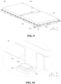
- FIG. 9 shows another schematic structural diagram of a box 20 of a battery 10 provided in an embodiment of the present application.
- the box 20 of the battery 10 provided in the embodiment of the present application may include a second position-limit member 220, and the second position-limit member 220 is disposed on a side of the box body 200 away from the battery cell to limit a relative displacement of the box 20 in the second direction z.
- the second direction z is parallel to the direction of gravity.
- the battery cell 100 is accommodated in an internal cavity of the box body 200, and the side of the box body 200 close to the battery cell 100 can be understood as an inner side of the box body 200, correspondingly, the side of the box body 200 away from the battery cell 100 can be understood as an outer side of the box body 200. Therefore, in the embodiment of the present application, the second position-limit member 220 is disposed on the outer side of the box body 200. After the box 20 is mounted on the electrical apparatus, the second position-limit member 220 can be used to limit the relative displacement of the box 20 in the direction z, that is, to limit the relative displacement of the box 20 in the direction of gravity z 2 and the opposite direction of gravity z 1 .
- the second position-limit member 220 is disposed on one side of the box body 200 of the battery box 20 away from the battery cell 100, the second position-limit member 220 can generate an acting force with the electrical apparatus in the second direction z after the box 20 is mounted on the electrical apparatus, that is, the second position-limit member 220 can generate an acting force in the direction of gravity z 2 and the opposite direction of gravity z 1 with the electrical apparatus, so as to limit the relative displacement of the box 20 in the direction of gravity z 2 and the opposite direction of gravity zi, thereby further improving the installation stability of the box 20 in the electrical apparatus and ensuring normal operations of the battery 10 and the electrical apparatus where the battery is located.
- the second position-limit member 220 provided in the embodiment of the present application may be disposed on the outer side of any wall of the box body 200, so that after the box 20 is mounted on the electrical apparatus, the second position-limit member 220 can abut against the electrical apparatus and generate an acting force in the direction of gravity z 2 and the opposite direction of gravity z with the electrical apparatus.
- the specific position of the second position-limit member 220 outside the box body 200 is not limited.
- the second position-limit member 220 may also be disposed on the first wall 201 of the box body 200 in the foregoing embodiments of the present application.
- FIG. 10 shows a schematic perspective view of a second position-limit member 220
- FIG. 10 may be a partial enlarged view of part B in FIG. 9
- FIG. 11 shows a schematic cross-sectional view of the second position-limit member 220 along a plane xz in FIG. 10 .
- the first wall 201 may include an extending portion 2012.
- the extending portion 2012 extends away from the battery cell 100 in the box body 200 along the first direction x, and the extending portion 2012 is used for arrangement of the second position-limit member 220 described above.
- the first wall 201 includes the extending portion 2012 extending along the first direction x and toward the outside of the box body 200, so that after the second position-limit member 220 is mounted on the extending portion 2012, it can be disposed opposite to the electrical apparatus in the second direction z, and the second position-limit member 220 and the electrical apparatus can be engaged with each other in the second direction z.
- the box body 200 may further include a second wall 202 perpendicular to a third direction y (i.e., the direction y shown in the figure). If the second position-limit member 220 is disposed on the second wall 202, the second wall 202 may also include an extending portion for arrangement of the second position-limit member 220, and the extending portion of the second wall 202 may extend to the outside of the box body 200 along the direction y.
- the box body 200 may also include a third wall 203 perpendicular to the second direction z.
- the second position-limit member 220 can be directly disposed on the outer side of the third wall 203, so as to be able to engage with the electrical apparatus.
- the second position-limit member 220 may be an elastic position-limit block, the elastic position-limit block is compressed to abut against the electrical apparatus after the box 20 is mounted on the electrical apparatus, so that there is an elastic force between the elastic position-limit block staying in a compressed state and the electrical apparatus; moreover, the elastic position-limit block is in closely press fit with the electrical apparatus in the second direction z, thereby ensuring the installation stability of the box 20 in the second direction z, that is, ensuring the Installation stability of the box 20 in the direction of gravity z 2 and the opposite direction of gravity z 1 of the electrical apparatus.
- the material of the elastic position-limit block in the embodiment of the present application includes but is not limited to a rubber material, which not only has no elasticity, but also has certain wear resistance and strength.
- a rubber material which not only has no elasticity, but also has certain wear resistance and strength.
- the compression amount of the elastic position-limit block can be above a specific threshold value, so as to ensure an acting force between elastic position-limit block and the electrical apparatus being above a specific threshold value.
- the threshold value of the compression amount of the elastic position-limit block may be or above 3 mm.
- a first end 2201 of the elastic position-limit block is provided with a chamfer structure, and the first end 2201 of the elastic position-limit block is an end of the elastic position-limit block facing toward the opposite direction of gravity z 1 .
- the first end 2201 of the elastic position-limit block facing toward the opposite direction of gravity is in contact with the electrical apparatus first, and acts on the electrical apparatus; based on the technical solution of the embodiment of the present application, the first end 2201 of the elastic position-limit block is provided with the chamfer structure, which can facilitate compressing the first end 2201 of the elastic position-limit block to the electrical apparatus; besides, compared with a sharp-edge structure, the chamfer structure can avoid a stress concentration, thereby prolonging service life of the elastic position-limit block. In addition, the chamfer structure can also beautify the elastic position-limit block.
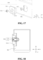
- FIG. 10 and FIG. 11 show an installation manner of the second position-limit member 220 on the extending portion 2012.
- the extending portion 2012 includes an accommodating area for accommodating the second position-limit member 220, so that the second position-limit member 220 can be mounted on the extending portion 2012.
- the elastic position-limit block has a protruding portion toward the extending portion 2012, and the extending portion 2012 has a clamping recess that matches with the protruding portion, so that the elastic position-limit block can be stably mounted on the extending portion 2012.
- the second position-limit member 220 can also be mounted on the extending portion 2012 in any other manner, for example, mounted on the extending portion 2012 through a fastener.
- the embodiment of the present application does not specifically limit thereto.
- the center of the first position-limit member 210 and the center of the second position-limit member 220 are located on a first plane, and the first plane is parallel to a plane determined by the first direction x and the second direction z, that is, the plane xz.
- the center of the first position-limit member 210 may be understood as the geometric center or the center of gravity of any module in the first position-limit member 210.
- the center of the first position-limit member 210 may be the geometric center or center of gravity of the first position-limit block 211 described above.
- the center of the second position-limit member 220 can also be understood as the geometric center or the center of gravity of any module in the second position-limit member 220.
- the center of the second position-limit member 220 may be the geometric center or center of gravity of the elastic position-limit block described above.
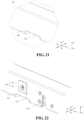
- FIG. 12 shows a schematic perspective view of a first position-limit member 210 and a second position-limit member 220 in an embodiment of the present application.
- the first position-limit member 210 and the second position-limit member 220 are both disposed on the first wall 201 of the box body 200, and the first position-limit member 210 and the second position-limit member 220 are adjacently arranged.
- the first position-limit member 210 may be disposed in a first region of the first wall 201
- the second position-limit member 220 may be disposed on the extending portion 2012, extending toward the outside of the box 20 along the first direction x, in the first region.
- the center of the first position-limit member 210 and the center of the second position-limit member 220 are located on a first plane, and the first plane is parallel to the plane xz.
- the first position-limit member 210 and the second position-limit member 220 are disposed on the same first wall 201 of the box body 200
- the first position-limit member 210 can be disposed on one first wall 201 in the box body 200
- the second position-limit member 220 can be symmetrically disposed on the other first wall 201 in the box body 200, where the center of the first position-limit member 210 and the center of the second position-limit member 220 may be located on the first plane that is parallel to the plane xz.
- the center of the first position-limit member 210 and the center of the second position-limit member 220 are both located on the first plane that is parallel to the plane xz. After the box 20 is mounted on the electrical apparatus, an acting force between the first position-limit member 210 and the electrical apparatus as well as an acting force between the second position-limit member 220 and the electrical apparatus is concentrated on the same plane, further improving the installation stability of the box 20 in the electrical apparatus.
- first position-limit member 210 and the second position-limit member 220 are adjacently arranged on the same first wall 201, the acting force between the first position-limit member 210 and second position-limit member 220 and the electrical apparatus is more concentrated, so that the installation stability of the box 20 in the electrical apparatus can be further improved; moreover, the first position-limit member 210 and the second position-limit member 220 are adjacently arranged, which also facilitates the installation and maintenance of the first position-limit member 210 and the second position-limit member 220.
- the box 20 may further include a first mounting member 230, which is disposed on a side of the first wall 201 of the box body 200 away from the battery cell, that is, disposed on the outer side of the first wall 201 of the box body 200.
- the first mounting member 230 is used to secure the box 20 to the electrical apparatus, and the first position-limit member 210 can be disposed adjacent to the first mounting member 230.
- the first mounting member 230 may be a locking portion.
- a locking mechanism and a channel may be provided in the electrical apparatus.
- the locking portion is configured to move in the channel.
- the locking mechanism is configured to lock the locking portion when the locking portion moves to a predetermined position of the channel, so that the box 20 can be secured on the electrical apparatus.
- the locking mechanism may also be configured to release the locking portion, and the locking portion is released from the channel so that the box 20 is released from the electrical apparatus.
- the first position-limit member 210 can generate an acting force with the electrical apparatus in the traveling direction of the electrical apparatus and the direction opposite to the traveling direction, so as to limit the box 20, and especially to limit a relative displacement of a component located around the first position-limit member 210 in the box 20 in the traveling direction of the electrical apparatus and the direction opposite to the traveling direction. Therefore, the component located around the first position-limit member 210 in the box 20 has a high stability.
- the first mounting member 230 for securing the box 20 and the first position-limit member 210 are adjacently arranged, which can improve the stability of the first mounting member 230, thereby further improving the installation stability of the box 20 in the electrical apparatus.
- FIG. 13 shows a schematic perspective view of a box 20 of a battery 10.
- FIG. 14 shows a schematic plan view of the box 20 in FIG. 13 along a plane xy.
- the box 20 may include a plurality of first position-limit members 210 and a plurality of the second position-limit members 220 described above.
- the plurality of first position-limit members 210 may be distributed on two first walls 201 in the box body 200 that are parallel to each other, and the plurality of second position-limit members 220 and the plurality of first position-limit members 210 are in one-to-one correspondence and are adjacently arranged.
- the box 20 further includes a plurality of first mounting pieces 230 described above, and the plurality of first mounting members 230 can be distributed at four corners of the box body 200 to ensure the stability of the box 20 in locking installation.
- the plurality of first mounting members 230 are distributed at the four corners of the box body 200 and are disposed on two first walls 201 that are parallel to each other. Further, the plurality of first mounting members 230 may be adjacently disposed and correspond to the first position-limit members 210 and the second position-limit members 220, so that the first position-limit members 210 and the second position-limit members 220 can ensure the installation stability of the first mounting member 230 and the box 20.
- FIG. 15 shows a schematic structural diagram of a holder 30 provided in an embodiment of the present application, and the holder 30 can be applied to an electrical apparatus.
- the electrical apparatus may be the electrical apparatus mentioned in the embodiments shown in FIG. 4 to FIG. 14 , and the electrical apparatus includes but is not limited to the vehicle 1 shown in FIG. 1 above.
- the holder 30 includes a holder body 300 for mounting the box 20 (not shown in the figure) of the battery 10 of the electrical apparatus, the box 20 being used for accommodating a battery cell 100; and a third position-limit member 310 disposed on a side of a first beam 301 of the holder body 300 close to the box 20, wherein an extension direction of the first beam 301 is perpendicular to a first direction x, the first direction x is parallel to a traveling direction of the electrical apparatus, and the third position-limit member 310 is used to limit a relative displacement of the box 20 in the first direction x.
- the box 20 of the battery 10 being mounted on the electrical apparatus in FIGS. 4 to 14 above can be understood as the box 20 of the battery 10 being mounted on the holder 30 in the following embodiments of the present application, and specifically being mounted on the holder body 300 in the holder 30.
- an extension direction of the first beam 301 in the holder body 300 is perpendicular to the first direction x, and the first direction x is parallel to the traveling direction of the electrical apparatus. If the traveling direction of the electrical apparatus is a length direction of the electrical apparatus, in the embodiment of the present application, the extension direction of the first beam 301 is perpendicular to the length direction of the electrical apparatus, that is, parallel to a width direction of the electrical apparatus.
- a third position-limit member 310 is disposed on a side of the first beam 301 close to the box 20, and the third position-limit member 310 is used to limit a relative displacement of the box 20 in the first direction x.
- the side of the first beam 301 close to the box 20 may also be referred to as an inner side of the first beam 301, and the inner side of the first beam 301 may be used to form a space for accommodating the box 20.
- the third position-limit member 310 disposed on the inner side of the first beam 301 is easy to engage with the box 20, thereby limiting relative displacements of the box 20 and the battery 10 located therein in the electrical apparatus.
- the extension direction of the first beam 301 provided with the third position-limit member 310 is perpendicular to the first direction x.
- the third position-limit member 310 can generate an acting force with the box 20 in the first direction x so as to limit a relative displacement of the box 20 in the first direction x in the holder body 300.
- the third position-limit member 310 is disposed on a side of the first beam 301 of the holder body 300 of the holder 30 close to the box 20 of the battery 10, the extension direction of the first beam 301 is perpendicular to the first direction x, and the first direction x is parallel to the traveling direction of the electrical apparatus, so that after the box 20 of the battery 10 is mounted on the holder body 300 of the electrical apparatus, the third position-limit member 310 can generate an acting force in the first direction x with the box 20, that is, the third position-limit member 310 can generate an acting force with the box 20 in the traveling direction of the electrical apparatus and the direction opposite to the traveling direction, so as to limit the relative displacement of the box 20 in the traveling direction of the electrical apparatus and the direction opposite to the traveling direction and improve installation stability of the box 20 in the traveling direction of the electrical apparatus and the direction opposite to the traveling direction, thereby reducing influence of the electrical apparatus in a traveling state on the battery 10 and its box 20, and ensuring normal operations of
- the third position-limit member 310 disposed on the holder body 300 may match with the first position-limit member 210 disposed on the box body 200 in the foregoing embodiments of the present application, the third position-limit member 310 and the first position-limit member 210 can generate an acting force in the traveling direction of the electrical apparatus and the direction opposite to the traveling direction to limit the relative displacement of the box 20 in the traveling direction of the electrical apparatus and the direction opposite to the traveling direction.
- FIG. 16 shows a schematic perspective view.
- FIG. 16 may be a partial enlarged view of part C in FIG. 15 .
- FIG. 17 shows a schematic exploded view of the third position-limit member 310.
- FIG. 18 shows a schematic cross-sectional view of the third position-limit member 310 along the plane xz in FIG. 16 .
- the plane xz is a plane determined according to the x direction and the direction z
- the direction x is the first direction x in the foregoing embodiments of the present application
- the direction z may be parallel to the direction of gravity, wherein the direction z includes the opposite direction of gravity z and the direction of gravity z 2 .
- the third position-limit member 310 may include a third position-limit block 311 and a second fastener 312.
- the second fastener 312 is used to fix the third position-limit block 311 to the first beam 301, and one end 3111 of the third position-limit block 311 facing toward the direction of gravity is provided with a wedge angle.
- the overall shape of the third position-limit block 311 may be similar to a block, with a mounting position provided in the middle; the second fastener 312 passes through the mounting position in the middle of the third position-limit block 311 so as to restrict the third position-limit block 311 to the first beam 301.
- the second fastener 312 includes, but is not limited to, a bolt and a nut, facilitating mounting and demounting of the third position-limit block 311.
- the third position-limit block 311 in the third position-limit member 310 is used to engage with the box 20 to prevent the relative displacement of the box 20.
- the third position-limit block 311 may be made of a wear-resistant material.
- the wear-resistant material includes but is not limited to a Polyoxymethylene (POM) material with high mechanical strength and rigidity.
- the box 20 can be mounted on the electrical apparatus toward the opposite direction of gravity zi, for example, the electrical apparatus is the vehicle 1, and the box 20 can be lifted and mounted on the holder 30 on a chassis of the vehicle 1, that is, the box 20 is mounted on the holder 30 in the vehicle 1 toward the opposite direction of gravity.
- an end 3111 of the third position-limit block 311 in the embodiment of the present application facing toward the opposite direction of gravity may be provided with a wedge angle, so that when mounting the box 20 on the holder 30, the box can be moved step by step toward the opposite direction of gravity z 1 by the aid of the end 3111 of the third position-limit block 311.
- the end 3111 can be used for guiding and positioning the box 20 when mounting the box 20 to the holder 30 so that the box 20 can be mounted in the holder 30 more conveniently.
- the holder 30 includes a third position-limit member 310, and the third position-limit member 310 can match with the first position-limit member 210 of the box 20 in the foregoing embodiments of the present application.
- the holder 30 may include the first position-limit member 210 described above, and the box 20 may include a third position-limit member 310, that is, even when the position-limit members in the holder 30 and the box 20 are interchanged, after the box 20 is mounted on the holder 30, the first position-limit member 210 and the third position-limit member 310 can still match with each other, so as to realize the stable installation of the box 20 in the holder 30.
- the structure of the first position-limit member 210 is a little more complicated, the buffer member 212 is required for to realize buffering of the first position-limit block 211.
- the first position-limit member 210 needs to be maintained and replaced frequently, and thus, it is convenient to maintain and replace the first position-limit member 210 since the first position-limit member 210 is disposed on the box 20.
- FIG. 19 shows a schematic plan view of a holder 30 provided in an embodiment of the present application.
- the holder 30 may include a plurality of third position-limit members 310 described above, and the plurality of third position-limit members 310 may be distributed on at least two first beams 301 in the holder body 300 that are parallel to each other.
- the extension directions of the at least two first beams 301 are both perpendicular to the first direction x, that is, perpendicular to the traveling direction of the electrical apparatus.
- the plurality of third position-limit members 310 are distributed on the at least two first beams 301, the third position-limit members 310 on the at least two first beams 301 in the holder body 300 each can generate an acting force in the first direction x with the box 20, so that the box 20 can be clamped with the holder body 300 in the first direction x, to further limit the relative displacement of the box 20 in the holder 30 along the first direction x, thereby improving the installation stability of the box 20 in the electrical apparatus.
- the plurality of third position-limit members 310 can be further distributed at the four corners of the space for accommodating the box 20 in the holder body 300, so as to be correspondingly disposed at the four corners of the box 20 to limit the relative displacements of the four corners of the box 20 in the holder 30, thereby comprehensively improving the installation stability of the box 20 in the holder 30 and the electrical apparatus where the box is located.
- the holder body 300 includes a first space 3100 and a second space 3200 that are used for accommodating the box 20, and a plurality of third position-limit members 310 are respectively disposed at four corners of the first space 3100 and second space 3200 to improve the installation stability of two boxes 20 mounted in the holder 30.
- FIG. 20 shows a schematic structural diagram of a holder 30 provided in an embodiment of the present application.
- the holder 30 provided in this embodiment of the present application may include a fourth position-limit member 320, the fourth position-limit member 320 being disposed on the holder body 300 for limiting a relative displacement of the box 20 in the second direction z, where the second direction z is parallel to the direction of gravity.
- the fourth position-limit member 320 may be disposed on any beam of the holder body 300. In some embodiments, it may be disposed on one side of any beam in the holder body 300 in the direction of gravity, or it may also be disposed on one side of any beam in the holder body 300 in the opposite direction of gravity.
- the holder body 300 is provided with the fourth position-limit member 320, the fourth position-limit member 320 can generate an acting force in the second direction with the box 20, that is, the fourth position-limit member 320 can generate an acting force in the direction of gravity z 1 and the opposite direction of gravity z 2 with the box 20, so as to limit the relative displacement of the box 20 in the direction of gravity z 1 and the opposite direction of gravity z 2 , thereby further improving installation stability of the box 20 in the holder 30 and ensuring normal operations of the battery 10 and the electrical apparatus where the battery is located.
- the fourth position-limit member 320 may also be disposed on the first beam 301 of the holder body 300 in the foregoing embodiments of the present application.
- FIG. 21 shows a schematic perspective view of the fourth position-limit member 320, and FIG. 21 may be a partial enlarged view of part B in FIG. 20 .
- the fourth position-limit member 320 includes a recess structure 321, the recess structure 321 is provided on one side of the first beam 301 in the direction of gravity z 2 , and the recess structure 321 has an opening towards the direction of gravity z 2 .
- the recess structure 321 disposed on one side of the first beam 301 in the direction of gravity z 2 is easy to be in contact fit with the box 20.
- the recess structure 321 can be used for accommodating a protruding component in the box 20 of the battery 10, so that the recess structure 321 can match with the protruding component in the box 20 and restrict the relative displacement of the box 20 in the holder body 300, thereby improving the installation stability of the box 20 in the holder 30.
- the recess structure 321 in the embodiment of the present application can match with the second position-limit member 220 in the foregoing embodiments of the present application.
- the recess structure 321 can be used for accommodating the second position-limit member 220, and is in closely press fit with the second position-limit member 220, so that the box 20 and the holder body 300 are clamped in the second direction z, thereby improving the installation stability of the box 20 in the gravitational direction of gravity z 2 and the opposite direction of gravity z 1 of the holder body 300.
- the recess structure 321 can not only realize the clamping of the box 20 and the holder body 300 in the second direction z, but also realize the position limiting of the box 20 and the holder body 300 in the third direction y, improving the installation stability of the body 20 on the holder body 300 in the third direction y.
- the material of the fourth position-limit member 320 includes but is not limited to a wear-resistant and rust-resistant material such as stainless steel, and the fourth position-limit member 320 can achieve a good close fit with the second position-limit member 220 in the box 20, such as an elastic position-limit block.
- the holder 30 includes the fourth position-limit member 320, and the fourth position-limit member 320 can match with the second position-limit member 220 of the box 20 in the foregoing embodiments of the present application.
- the holder 30 may include the second position-limit member 220 described above, and the box 20 may include a fourth position-limit member 320, that is, even when the position-limit members in the holder 30 and the box 20 are interchanged, after the box 20 is mounted on the holder 30, the second position-limit member 220 and the fourth position-limit member 320 can still match with each other, so as to realize the stable installation of the box 20 in the holder 30.
- the second position-limit member 220 is an elastic position-limit block, compared with the fourth position-limit member 320, the second position-limit member 220 needs to be repaired or replaced more frequently. Therefore, it is convenient to maintain and replace the second position-limit member 220 since the second position-limit member 220 is disposed on the box 20.
- the center of the third position-limit member 310 and the center of the fourth position-limit member 320 are located on a first plane, and the first plane is parallel to a plane determined by the first direction x and the second direction z.
- the center of the third position-limit member 310 may be understood as the geometric center or the center of gravity of any module in the third position-limit member 310.
- the center of the third position-limit member 310 may be the geometric center of the third position-limit member 311 described above.
- the center of the fourth position-limit member 320 may also be understood as the geometric center or center of gravity of any module in the fourth position-limit member 320.
- the center of the fourth position-limit member 320 may be the geometric center of the recess structure 321.
- FIG. 22 shows a schematic perspective view of a third position-limit member 310 and a fourth position-limit member 320 in an embodiment of the present application.
- both the third position-limit member 310 and the fourth position-limit member 320 may be disposed on the same first beam 301 of the holder body 300, and the third position-limit member 310 and the fourth position-limit member 320 are adjacently arranged.
- the third position-limit member 310 and the fourth position-limit member 320 are disposed on two sides of the first beam 301 that are perpendicular to and adjacent to each other.
- the center of the third position-limit member 310 and the center of the fourth position-limit member 320 are located on a first plane, and the first plane is parallel to the plane xz.
- the third position-limit member 310 and the fourth position-limit member 320 are disposed on the same first beam 301 of the holder body 300
- the third position-limit member 310 can be disposed on one first beam 301 in the holder body 300
- the fourth position-limit member 320 can be disposed on the other first beam 301 in the holder body 300, where the center of the third position-limit member 310 and the center of the fourth position-limit member 320 may also be located on the first plane that is parallel to the plane xz.
- the center of the third position-limit member 310 and the center of the fourth position-limit member 320 are both located on the first plane that is parallel to the plane xz. After the box 20 is mounted on the holder 30, an acting force between the third position-limit member 310 and the box 20 as well as an acting force between the fourth position-limit member 320 and the box 20 is concentrated on the same plane, further improving the installation stability of the box 20 in the holder 30.
- the acting force between the third position-limit member 310 and fourth position-limit member 320 and the box 20 is more concentrated, so that the installation stability of the box 20 in the holder 30 can be further improved; moreover, the third position-limit member 310 and the fourth position-limit member 320 are adjacently arranged, which also facilitates the installation and maintenance of the third position-limit member 310 and the fourth position-limit member 320.
- the holder 30 may further include a second mounting member 330, the second mounting member 330 being used to lock the box 20 on the holder body 300.
- the third position-limit member 310 can be arranged adjacent to the second mounting members 330.
- the second mounting member 330 may include a locking mechanism and a channel, which may engage with the first mounting member 230 in the box 20 (e.g., the locking portion shown in FIG. 12 ), realizing locking and releasing of the box 20 in the holder 30.
- the second mounting member 330 for securing the box 20 and the third position-limit member 310 are adjacently arranged, under a position limiting effect of the third position-limit member 310, the reliability in locking installation of the box 20 by the second mounting member 330 can be improved, thereby further improving the installation stability of the box 20 in the holder 30.
- the fourth position-limit member 320 and the third position-limit member 310 are adjacently arranged, the fourth position-limit member 320 and the second mounting member 330 are also adjacently arranged, thereby further improving the reliability in locking installation of the box 20 by the second mounting member 330 and the installation stability of the box 20 in the holder 30.
- FIG. 23 shows a schematic perspective view of a holder 30.
- FIG. 24 shows a schematic plan view of the box 20 in FIG. 23 along a plane xy.
- the holder 30 may include a plurality of the above-mentioned third position-limit members 310 and a plurality of the above-mentioned fourth position-limit members 320.
- the plurality of third position-limit members 310 may be distributed on at least one first beam 301 in the holder body 200, and the plurality of fourth position-limit members 320 and the plurality of third position-limit members 310 are in one-to-one correspondence and are adjacently arranged.
- the holder 30 further includes a plurality of the above-mentioned second mounting members 330.
- the plurality of second mounting members 330 may be distributed at the four corners of a space for accommodating the box 20 in the holder body 300, so as to be correspondingly disposed at the four corners of the box 20 to limit the relative displacements of the four corners of the box 20 in the holder 30, thereby comprehensively improving the installation stability of the box 20 in the holder 30 and the electrical apparatus where the box is located.
- the holder body 300 includes two spaces, i.e., a space 3100 and a space 3200 for accommodating the box 20, and a plurality of second mounting members 330 are distributed at four corners of the space 3100 and the space 3200 respectively, and are disposed on two first beams 301 that are parallel to each other.
- the plurality of second mounting members 330 may be adjacently disposed and correspond to the third position-limit members 310 and the fourth position-limit members 320, so that the third position-limit members 310 and the fourth position-limit members 320 can ensure the reliability in locking installation of the box 20 by the second mounting members 330 and the installation stability of the box 20 in the holder 30.
- An embodiment of the present application further provides a battery 10.
- the battery 10 may include a battery cell 100, and the box 20 described in the foregoing embodiments, the box 20 being used for accommodating the battery cell 100.
- An embodiment of the present application further provides an electrical apparatus, and the electrical apparatus may include the battery 10 in the foregoing embodiments and the holder 30 in the foregoing embodiments.
- a third position-limit member 310 in the holder 30 matches with a first position-limit member 210 in the battery 10 to limit a relative displacement of the battery 10 in a first direction x.
- the battery 10 is configured to provide electrical energy for the electrical apparatus.
- the electrical equipment may be a vehicle 1, a ship or a spacecraft.
- the box 20 of the battery 10, the battery 10, and the electrical apparatus of the embodiments of the present application are described above, and a method and device for preparing a battery of the embodiments of the present application will be described below.
- a method and device for preparing a battery of the embodiments of the present application will be described below.
- FIG. 25 shows a schematic flowchart of a method 400 for preparing a battery according to an embodiment of the present application. As shown in FIG. 25 , the method 400 may include:
- FIG. 26 shows a schematic block diagram of a device 500 for preparing a battery according to an embodiment of the present application.
- the device 500 for preparing a battery may include: a first providing module 510, a second providing module 520 and a mounting module 530.
- the first providing module 510 is configured to provide a battery cell 100.
- the second providing module 520 is configured to provide a box 20, the box 20 including a box body 200 for accommodating a battery cell 100; a first position-limit member 210 disposed on a side of a first wall 201 of the box body 200 away from the battery cell 100, wherein the first wall 201 is perpendicular to a first direction x, the first direction x is parallel to a traveling direction of an electrical apparatus after the box 200 is mounted on the electrical apparatus, and the first position-limit member 210 is used to limit a relative displacement of the box 20 in the first direction x.
- the mounting module 530 is used for accommodating the battery cell 100 in the box 20.
Landscapes
- Chemical & Material Sciences (AREA)
- Chemical Kinetics & Catalysis (AREA)
- Electrochemistry (AREA)
- General Chemical & Material Sciences (AREA)
- Engineering & Computer Science (AREA)
- Aviation & Aerospace Engineering (AREA)
- Combustion & Propulsion (AREA)
- Transportation (AREA)
- Mechanical Engineering (AREA)
- Battery Mounting, Suspending (AREA)
- Arrangement Or Mounting Of Propulsion Units For Vehicles (AREA)
Abstract
Description
- Embodiments of the present application relate to the field of batteries, and more particularly, to a battery box, a battery, a holder, and an electrical apparatus.
- Energy saving and emission reduction is the key to sustainable development of the automobile industry. In this case, electric vehicles have become an important part of the sustainable development of the automobile industry because of their advantages of energy saving and environmental protection. For electric vehicles, battery technologies are an important factor related to their development.
- In the development of the battery technologies, the installation stability of batteries is also a non-negligible issue in addition to the improvement of performance of the batteries. Therefore, how to enhance the installation stability of the batteries is an urgent technical problem to be solved in the battery technologies.
- The present application provides a battery box, a battery, a holder, and an electrical apparatus, which can enhance installation stability of the battery.
- In a first aspect, a battery box is provided, including a box body for accommodating a battery cell; a first position-limit member disposed on a side of a first wall of the box body away from the battery cell, wherein the first wall is perpendicular to a first direction, the first direction is parallel to a traveling direction of an electrical apparatus after the box is mounted on the electrical apparatus, and the first position-limit member is used to limit a relative displacement of the box in the first direction.
- Based on the technical solution of embodiments of the present application, the first position-limit member is disposed on the side of the first wall of the box body away from the battery cell, the first wall is perpendicular to the first direction, and the first direction is parallel to a traveling direction of the electrical apparatus after the box is mounted on the electrical apparatus, so that after the box is mounted on the electrical apparatus, the first position-limit member can generate an acting force in the first direction with the electrical apparatus, that is, the first position-limit member can generate an acting force with the electrical apparatus in the traveling direction of the electrical apparatus and the direction opposite to the traveling direction, so as to limit a relative displacement of the box in the traveling direction of the electrical apparatus and the direction opposite to the traveling direction and improve installation stability of the box in the traveling direction of the electrical apparatus and the direction opposite to the traveling direction, thereby reducing influence of the electrical apparatus in a traveling state on the battery and its box, and ensuring normal operations of the battery and the electrical apparatus where the battery is located.
- In some possible embodiments, the box further includes a second position-limit member disposed on a side of the box away from the battery cell and used to limit a relative displacement of the box in a second direction, the second direction being parallel to the direction of gravity after the box is mounted on the electrical apparatus.
- Based on the technical solution of the embodiments, the second position-limit member is disposed on the side of the box away from the battery cell, the second position-limit member can generate an acting force in the second direction with the electrical apparatus after the box is mounted on the electrical apparatus, that is, the second position-limit member can generate an acting force in the direction of gravity and the opposite direction of gravity with the electrical apparatus, so as to limit a relative displacement of the box in the direction of gravity and the opposite direction of gravity, thereby further improving the installation stability of the box in the electrical apparatus and ensuring normal operations of the battery and the electrical apparatus where the battery is located.
- In some possible embodiments, the first position-limit member includes a first position-limit block and a buffer block, wherein the first position-limit block is disposed on the first wall and can move along the first direction, the buffer block is disposed between the first position-limit block and the first wall, and the buffer block is used to provide a buffer distance of the first position-limit block in the first direction.
- Based on the technical solution of the embodiments, when mounting the box on the electrical apparatus, the first position-limit block can move toward the inside of the box along the first direction through the matching between the buffer block and the first position-limit block, and the first position-limit block can not bring too much installation resistance, facilitating installation of the box on the electrical apparatus. Further, after the box is mounted on the electrical apparatus, the first position-limit block compresses the buffer block, the buffer block is then in a compressed state to provide an elastic acting force to the first position-limit block, so that the first position-limit block is in closely press fit with the electrical apparatus in the first direction, thereby ensuring the installation stability of the box in the first direction, that is, ensuring the installation stability of the box in the travel direction and the opposite traveling direction of the electrical apparatus.
- In some possible embodiments, the first position-limit member further includes a first fastener, wherein the first position-limit block is disposed on the first wall through the first fastener, and the first fastener is used to provide a buffer space for the first position-limit block and the buffer block in the first direction.
- Based on the technical solution of the embodiments, the first position-limit block is disposed on the first wall of the box by the first fastener, and the buffer space is provided for the first position-limit block and the buffer block, so that the first position-limit block can generate a relative displacement in the first direction through the buffer block, thereby facilitating the installation of the box on the electrical apparatus and the installation stability of the box in the first direction.
- In some possible embodiments, a first end of the first position-limit block is provided with a wedge angle, and the first end of the first position-limit block is an end of the first position-limit block facing toward the opposite direction of gravity.
- Based on the technical solution of the embodiments, when mounting the box on the electrical apparatus facing toward the opposite direction of gravity, the first end with the wedge angle in the first position-limit block can be gradually moved in the opposite direction of gravity, and the first end can be used for guiding and positioning of the box when mounting the box in the electrical apparatus, so that the box can be mounted in the electrical apparatus more conveniently.
- In some possible embodiments, the second position-limit member is an elastic position-limit block, and the elastic position-limit block is compressed to abut against the electrical apparatus after the box is mounted on the electrical apparatus.
- Based on the technical solution of the embodiments, the second position-limit member is an elastic position-limit block, the elastic position-limit block is compressed to abut against the electrical apparatus after the box is mounted on the electrical apparatus, so that there is an elastic force between the elastic position-limit block staying a compressed state and the electrical apparatus; moreover, the elastic position-limit block is in closely press fit with the electrical apparatus in the second direction, thereby ensuring the installation stability of the box in the second direction, that is, ensuring the installation stability of the box in the direction of gravity and the opposite direction of gravity of the electrical apparatus.
- In some possible embodiments, a first end of the elastic position-limit block is provided with a chamfer structure, and the first end of the elastic position-limit block is an end of the elastic position-limit block facing toward the opposite direction of gravity.
- Based on the technical solution of the embodiments, when mounting the box on the electrical apparatus in the opposite direction of gravity, the first end of the elastic position-limit block facing toward the opposite direction of gravity is in contact with the electrical apparatus first, and acts on the electrical apparatus; the first end of the elastic position-limit block is provided with a chamfer structure, which can facilitate compressing the first end of the elastic position-limit block to the electrical apparatus; besides, compared with a sharp-edge structure, the chamfer structure can avoid a stress concentration, thereby prolonging service life of the elastic position-limit block. In addition, the chamfer structure can also beautify the elastic position-limit block.
- In some possible embodiments, the first wall is provided with an accommodating area, the accommodating area being used for accommodating the first position-limit member.
- Based on the technical solution of the embodiments, the first wall of the box is provided with the accommodating area for accommodating the first position-limit member; on the one hand, a mounting space of the first position-limit member can be saved, and on the other hand, the first position-limit member can also be protected by the accommodating area, and is prevented from being damaged by external influences, thereby prolonging service life of the first position-limit member in the box.
- In some possible embodiments, the first wall includes an extending portion, the extending portion extending along the first direction and away from the battery cell, and being used for arrangement of the second position-limit member.
- In some possible embodiments, the center of the first position-limit member and the center of the second position-limit member are located on a first plane, the first plane being parallel to the plane determined by the first direction and the second direction.
- Based on the technical solution of the embodiments, the center of the first position-limit member and the center of the second position-limit member are both located on the first plane that is parallel to the plane determined by the first direction and the second direction. When the box body is mounted on the electrical apparatus, an acting force between the first position-limit member and the electrical apparatus as well as an acting force between the second position-limit member and the electrical apparatus is concentrated on the same plane, further improving the installation stability of the box in the electrical apparatus. Further, if the first position-limit member and the second position-limit member are adjacently arranged on the same first wall, the acting force between the first position-limit member and the second position-limit member and the electrical apparatus is more concentrated, so that the installation stability of the box body in the electrical apparatus can be further improved; moreover, the first position-limit member and the second position-limit member are adjacently arranged, which also facilitates the installation and maintenance of the first position-limit member and the second position-limit member.
- In some possible embodiments, the box body includes a plurality of first position-limit members, the plurality of first position-limit members being distributed on two first walls of the box body that are parallel to each other.
- Based on the technical solution of the embodiments, using the space of the two first walls, the plurality of first position-limit members are distributed on the two first walls, the first position-limit members on the two first walls of the box each can generate an acting force in the first direction with the electrical apparatus, so that the box can be clamped with the electrical apparatus in the first direction, to further limit the relative displacement of the box in the electrical apparatus along the first direction, thereby improving the installation stability of the box in the electrical apparatus.
- In some possible embodiments, a plurality of first position-limit members are distributed at four corners of the box body.
- Based on the technical solution of the embodiments, the plurality of first position-limit members provided in the box are distributed at the four corners of the box body to limit a relative displacement of the four corners of the box body in the electrical apparatus, thereby improving the installation stability of the box in electrical installations.
- In a second aspect, provided is a holder, which is applied to an electrical apparatus, and includes a holder body for mounting of a battery box of the electrical apparatus, wherein the box is used for accommodating battery cells; a third position-limit member disposed on a side of a first beam of the holder body close to the box, wherein an extension direction of the first beam is perpendicular to a first direction, the first direction is parallel to a traveling direction of the electrical apparatus, the third position-limit member is used to limit a relative displacement of the box in the first direction.
- Based on the technical solution of the embodiment of the present application, the third position-limit member is disposed on a side of the first beam of the holder body close to the battery box, the extension direction of the first beam is perpendicular to the first direction, and the first direction is parallel to the traveling direction of the electrical apparatus, so that after the box is mounted on the holder body of the electrical apparatus, the third position-limit member can generate an acting force in the first direction with the electrical apparatus, that is, the third position-limit member can generate an acting force with the electrical apparatus in the traveling direction of the electrical apparatus and the direction opposite to the traveling direction, so as to limit the relative displacement of the box in the traveling direction of the electrical apparatus and the direction opposite to the traveling direction and improve installation stability of the box in the traveling direction of the electrical apparatus and the direction opposite to the traveling direction, thereby reducing influence of the electrical apparatus in a traveling state on the battery and its box, and ensuring normal operations of the battery and the electrical apparatus where the battery is located.
- In some possible embodiments, the holder further includes a fourth position-limit member disposed on the holder body and used to limit a relative displacement of the box in a second direction, the second direction being parallel to the direction of gravity.
- Based on the technical solution of the embodiments, the fourth position-limit member is disposed on the holder body, the fourth position-limit member can generate an acting force with the electrical apparatus in the second direction, that is, the fourth position-limit member can generate an acting force in the direction of gravity and the opposite direction of gravity with the box, so as to limit the relative displacement of the box in the direction of gravity and the opposite direction of gravity, thereby further improving installation stability of the box in the electrical apparatus and ensuring normal operations of the battery and the electrical apparatus where the battery is located.
- In some possible embodiments, the fourth position-limit member includes a recess structure, the recess structure having an opening facing toward the direction of gravity.
- In some possible embodiments, after the battery box is mounted on the holder body, the recess structure is used for accommodating the second position-limit member of the box, so as to limit the relative displacement of the box in the second direction.
- Based on the technical solution of the embodiments, the recess structure can match with the second position-limit member in the battery box, and the recess structure can be used for accommodating the second position-limit member and is in closely press fit with the second position-limit member, so that the box and the holder body are clamped the second direction, improving the installation stability of the box in the direction of gravity and the opposite direction of gravity of the holder body.
- In some possible embodiments, the third position-limit member includes a third position-limit block and a second fastener, wherein the second fastener is used to fix the third position-limit block to the first beam, and an end of the third position-limit block facing toward the direction of gravity is provided with a wedge angle.
- Based on the technical solution of the embodiments, the end of the third limit block facing toward the opposite direction of gravity can be provided with the wedge angle, so that when mounting the box on the holder facing toward the opposite direction of gravity, the box can be moved step by step toward the opposite direction of gravity by the aid of the end of the third position-limit block that is provided with the wedge angle. The end provided with the wedge angle can be used for guiding and positioning the box when mounting the box to the holder so that the box can be mounted in the holder more conveniently.
- In some possible embodiments, the center of the third position-limit member and the center of the fourth position-limit member are located on a first plane, the first plane being parallel to a plane determined by the first direction and the second direction.
- Based on the technical solution of the embodiments, the center of the third position-limit member and the center of the fourth position-limit member are both located on the first plane that is parallel to the plane determined by the first direction and the second direction. After the box body is mounted on the holder, an acting force between the third position-limit member and the box as well as an acting force between the fourth position-limit member and the box is concentrated on the same plane, further improving the installation stability of the box in the holder. Further, if the third position-limit member and the fourth position-limit member are adjacently arranged on the same first wall, an acting force between the third position-limit member and fourth position-limit member and the electrical apparatus is more concentrated, so that the installation stability of the box in the holder can be further improved; moreover, the third position-limit member and the fourth position-limit member are adjacently arranged, which also facilitates the installation and maintenance of the third position-limit member and the fourth position-limit member.
- In some possible embodiments, the holder includes a plurality of third position-limit members, the plurality of first position-limit members being distributed on two first beams of the holder body that are parallel to each other.
- Based on the technical solution of the embodiments, using a space of at least two first beams, the plurality of third position-limit members are distributed on the at least two first beams, the third position-limit members on the at least two first beams of the holder body each can generate an acting force in the first direction with the box, so that the box can be clamped with the holder body in the first direction, to further limit the relative displacement of the box in the holder in the first direction, thereby improving the installation stability of the box in the electrical apparatus.
- In some possible embodiments, the plurality of third position-limit members are distributed at four corners of a space for accommodating the box body in the holder body.
- Based on the technical solution of the embodiments, the plurality of third position-limit members can be further distributed at the four corners of the space for accommodating the box in the holder body, so as to be correspondingly disposed at the four corners of the box to limit relative displacements of the four corners of the box in the holder, thereby comprehensively improving the installation stability of the box in the holder and the electrical apparatus where the box is located.
- In a third aspect, a battery is provided, including a battery cell and the battery box in the first aspect or any possible embodiment of the first aspect, wherein the box is used for accommodating the battery cell.
- In a fourth aspect, an electrical apparatus is provided, including the battery in the third aspect, and the holder in the second aspect or any possible embodiment of the second aspect, wherein the third position-limit block of the holder matches with the first position-limit member of the battery to limit a relative displacement of the battery in the first direction.
- In a fifth aspect, a method for preparing a battery is provided, including providing a box cell; providing a box, the box including a box body for accommodating the battery cell; a first position-limit member disposed on a side of a first wall of the box body away from the battery cell, wherein the first wall is perpendicular to a first direction, the first direction is parallel to a traveling direction of an electrical apparatus after the box is mounted on the electrical apparatus, and the first position-limit member is used to limit a relative displacement of the box in the first direction; and accommodating the battery cell in the box.
- In a sixth aspect, a device for preparing a battery box body is provided, including a first providing module for providing a battery cell; a second providing module for providing a box, the box including a box body for accommodating the battery cell; a first position-limit member disposed on a side of a first wall of the box body away from the battery cell, wherein the first wall is perpendicular to a first direction, the first direction is parallel to a traveling direction of an electrical apparatus after the box is mounted on the electrical apparatus, and the first position-limit member is used to limit a relative displacement of the box in the first direction; and a mounting module for accommodating the battery cell in the box.
- Based on the technical solution of the embodiments of the present application, the first position-limit member is disposed on the side of the first wall of the box body away from the battery cell, the first wall is perpendicular to the first direction, and the first direction is parallel to a traveling direction of an electrical apparatus after the box is mounted on the electrical apparatus, so that after the box is mounted on the electrical apparatus, the first position-limit member can generate an acting force in the first direction x with the electrical apparatus, that is, the first position-limit member can generate an acting force with the electrical apparatus in the traveling direction of the electrical apparatus and the direction opposite to the traveling direction, so as to limit a relative displacement of the box in the traveling direction of the electrical apparatus and the direction opposite to the traveling direction and improve installation stability of the box in the traveling direction of the electrical apparatus and the direction opposite to the traveling direction, thereby reducing influence of the electrical apparatus staying in a traveling state on the battery and its box, and ensuring normal operations of the battery and the electrical apparatus where the battery is located.
- In order to illustrate the technical solutions of the examples of the present application more clearly, the drawings required in the examples of the present application will be briefly introduced below. Obviously, the drawings described below are only some examples of the present application. For those of ordinary skill in the art, other drawings can also be obtained according to the drawings without any creative effort.
-
FIG. 1 is a schematic structural diagram of a vehicle according to an embodiment of the present application; -
FIG. 2 is a schematic structural diagram of a battery according to an embodiment of the present application. -
FIG. 3 is a schematic structural diagram of a holder body provided in a vehicle according to an embodiment of the present application; -
FIG. 4 is a schematic structural diagram of a battery box according to an embodiment of the present application; -
FIG. 5 is a schematic perspective view of a first position-limit member according to an embodiment of the present application; -
FIG. 6 is a schematic exploded view of a first position-limit member according to an embodiment of the present application; -
FIG. 7 is a schematic cross-sectional view of a first position-limit member according to an embodiment of the present application; -
FIG. 8 is a schematic plan view of a battery box according to an embodiment of the present application; -
FIG. 9 is a schematic structural diagram of a battery box according to an embodiment of the present application; -
FIG. 10 is a schematic perspective view of a second position-limit member according to an embodiment of the present application; -
FIG. 11 is a schematic cross-sectional view of a second position-limit member according to an embodiment of the present application; -
FIG. 12 is a schematic perspective view of a first position-limit member and a second position-limit member according to an embodiment of the present application; -
FIG. 13 is a schematic structural diagram of a battery box according to an embodiment of the present application; -
FIG. 14 is a schematic plan view of a battery box according to an embodiment of the present application; -
FIG. 15 is a schematic structural diagram of a holder according to an embodiment of the present application; -
FIG. 16 is a schematic perspective view of a third position-limit member according to an embodiment of the present application; -
FIG. 17 is a schematic exploded view of a third position-limit member according to an embodiment of the present application; -
FIG. 18 is a schematic cross-sectional view of a third position-limit member according to an embodiment of the present application; -
FIG. 19 is a schematic plan view of a holder according to an embodiment of the present application; -
FIG. 20 is a schematic structural diagram of a holder according to an embodiment of the present application; -
FIG. 21 is a schematic perspective view of a fourth position-limit member according to an embodiment of the present application; -
FIG. 22 is a schematic perspective view of a third position-limit member and a fourth position-limit member according to an embodiment of the present application; -
FIG. 23 is a schematic structural diagram of a holder according to an embodiment of the present application; -
FIG. 24 is a schematic plan view of a holder according to an embodiment of the present application; -
FIG. 25 is a schematic flowchart of a method for preparing a battery according to an embodiment of the present application; and -
FIG. 26 is a schematic block diagram of a device for preparing a battery according to an embodiment of the present application. - In the drawings, the drawings are not drawn to actual scale.
-
-
vehicle 1,controller 13,motor 14; -
battery 10,battery cell 100; -
box 20,first portion 2100,second portion 2200; -
box body 200,first wall 201,accommodating area 2011, extendingportion 2012,second wall 202,third wall 203; - first position-
limit member 210, first position-limit block 211,buffer block 212,first fastener 213; - second position-
limit member 220; - first mounting
member 230; -
holder 30; -
holder body 300,first beam 301,second beam 302; - third position-
limit member 310, third position-limit block 311,second fastener 312; - fourth position-
limit member 320,recess structure 321, - first direction x, second direction z, third direction y, opposite direction of gravity zi, and direction of gravity z2.
- The embodiments of the present application are further described in detail below with reference to the drawings and embodiments. The following detailed description of the examples and the drawings are used to illustrate the principles of the present application by way of example, but should not be used to limit the scope of the present application, that is, the present application is not limited to the described examples.
- In the description of the present application, it should be noted that, unless otherwise stated, "plurality of" means two or more; the orientation or positional relationships indicated by the terms "upper", "lower", "left", "right", "inner" and "outer" are only for facilitating the description of the present application and simplifying the description, rather than indicating or implying that the apparatus or element referred to must have a particular orientation or be constructed and operated in a particular orientation, and therefore will not be interpreted as position-limit the present application. In addition, the terms "first", "second" and "third" are used for descriptive purposes only, and cannot be construed as indicating or implying relative importance. "Vertical" is not strictly vertical, but within an allowable range of errors. "Parallel" is not strictly parallel, but within an allowable range of errors.
- Orientation words appearing in the following description are all directions shown in the drawings, and do not limit the specific structure of the present application. In the description of the present application, it should also be noted that, unless otherwise expressly specified and limited, the terms "mount," "connected," and "connecting" should be broadly understood, for example, they may be a fixed connection or a detachable connection or be an integrated connection; or may be a direct connection or an indirect connection through an intermediate medium. For those of ordinary skill in the art, the specific meanings of the above terms in the present application may be understood according to specific circumstances.
- In the present application, the term "and/or" is only an association relationship for describing associated objects, indicating that three relationships may exist. For example, A and/or B may represent three situations: A exists alone, both A and B exist, and B exists alone. In addition, the character "/" in the present application generally means that the associated objects before and after it are in an "or" relationship.
- Unless otherwise defined, all technical and scientific terms used in the present application have the same meanings as those commonly understood by those skilled in the art to which the present application belongs. The terms used in the specification of the present application are merely for the purpose of describing specific examples, but are not intended to limit the present application. The terms "comprising" and "having" and any variations thereof in the specification and the claims of the present application as well as the foregoing description of the drawings are intended to cover non-exclusive inclusions. The terms "first", "second" and the like in the specification and the claims of the present application as well as the above drawings are used to distinguish different objects, rather than to describe a specific order or primary-secondary relationship.
- Reference herein to "an embodiment" means that a particular feature, structure, or characteristic described in connection with the embodiment can be included in at least one embodiment of the present application. The appearance of this phrase in various places in the specification does not necessarily refer to the same embodiment, nor is it a separate or alternative embodiment that is mutually exclusive with other embodiments. It is understood explicitly and implicitly by those skilled in the art that the embodiments described in the present application can be combined with other embodiments.
- In the present application, a battery cell may include a lithium-ion secondary battery, a lithium-ion primary battery, a lithium-sulfur battery, a sodium/lithium-ion battery, a sodium-ion battery, or a magnesium-ion battery, etc., which is not limited in the examples of the present application. The battery cell may be cylindrical, flat, rectangular, or in other shapes, which is also not limited in the examples of the present application. The battery cells are generally divided into three types according to packaging manners: cylindrical battery cells, rectangular battery cells, and pouch cells, which are not limited in the examples of the present application.
- The battery mentioned in the examples of the present application refers to a single physical module including one or more battery cells to provide a higher voltage and capacity. For example, the battery mentioned in the present application may include a battery module, a battery pack, or the like. The battery typically includes a box body for encapsulating one or more battery cells. The box body can prevent liquids or other foreign matters from affecting charging or discharging of the battery cells.
- Many design factors, such as energy density, cycle life, discharge capacity, charge-discharge rate, and safety performance of a battery, should be considered in the development of the battery technology. In addition, the installation safety of the battery also needs to be taken into account.
- Specifically, in an application process, a battery is generally mounted in an electrical apparatus to provide electrical energy for the electrical apparatus. If the battery is mounted in the electrical apparatus in an unstable manner and the stability is poor, when the electrical apparatus stays in a motion state, especially when it stays in a motion state with an acceleration, a specific external force is generated on the battery, causing the battery to have a relative displacement in the electrical apparatus or even be out of a fixed mounting position, thereby affecting an electrical connection between the battery and the electrical apparatus, and affecting performance of the battery. Eventually, it may lead to an abnormal operation of the electrical apparatus and bring certain safety hazards.
- Based on this, the present application provides a battery box for accommodating a battery cell. The box includes a first position-limit member. After the box is mounted on the electrical apparatus, the first position-limit member is used to limit a relative displacement of the battery in a traveling direction of the electrical apparatus. Correspondingly, the present application further provides a holder, which is applied to an electrical apparatus. The holder is used for mounting of a battery of the electrical apparatus. The holder includes a third position-limit member. After the battery box is mounted on the electrical apparatus, the third position-limit member can also be used to limit the relative displacement of the battery in the traveling direction of the electrical apparatus.
- In some application scenarios, the electrical apparatus is generally moved along its traveling direction, and may generate a motion with an acceleration, which has a greater impact on the battery. By providing the first position-limit member on the battery box, and/or, providing the third position-limit member on the holder of the electrical apparatus, the installation stability of the battery in the electrical apparatus, especially the installation stability in the traveling direction of the electrical apparatus can be enhanced, thereby ensuring normal operations of the battery and the electrical apparatus where the battery is located.
- The technical solutions described in the embodiments of the present application are all applicable to various electrical apparatuses using batteries, such as electric vehicles, electric toys, electric tools, ships, spacecrafts, and the like. For example, the spacecrafts include airplanes, rockets, space shuttles, spaceships, etc.
- It should be understood that the technical solutions described in the examples of the present application are not only applicable to the electrical apparatuses described above, but also applicable to all apparatuses and devices using batteries. However, for the sake of brevity, the following embodiments are described by taking an electric vehicle as an example.
- For example,
FIG. 1 is a schematic structural diagram of avehicle 1 according to an embodiment of the present application. Thevehicle 1 may be a fuel vehicle, a gas vehicle, or a new energy vehicle, and the new energy vehicle may be an all-electric vehicle, a hybrid electric vehicle, an extended range electric vehicle, or the like. The interior ofvehicle 1 may be provided with amotor 14, acontroller 13, and abattery 10, andcontroller 13 is configured to control thebattery 10 to supply power to themotor 14. For example, thebattery 10 may be arranged at the bottom or the head or the tail of thevehicle 1. Thebattery 10 may be configured to supply power to thevehicle 1, for example, thebattery 10 may be used as an operating power source of thevehicle 1, which is used for a circuit system of thevehicle 1, for example, for operation power requirements of thevehicle 1 during starting, navigation and running. In another embodiment of the present application, thebattery 10 can not only be used as the operating power source ofvehicle 1, but also can be used as a driving power source ofvehicle 1 to provide driving power forvehicle 1 instead of or partially instead of fuel or natural gas. - In order to meet different power requirements, the battery may include a plurality of battery cells. The plurality of battery cells may be in series connection, in parallel connection, or in parallel-series connection, and the parallel-series connection refers to mixing of the series connection and the parallel connection. The battery may also be called a battery pack. Optionally, the plurality of battery cells may be in series connection, in parallel connection, or in parallel-series connection to form a battery module first, and a plurality of battery modules may then be in series connection, in parallel connection, or in parallel-series connection to form a battery. That is, the plurality of battery cells may directly form a battery, or form a battery module first, and then the battery module forms a battery.
- For example,
FIG. 2 is a schematic structural diagram of abattery 10 according to an embodiment of the present application, where thebattery 10 may include a plurality ofbattery cells 100. Thebattery 10 may further include a box body 200 (or a cover body), the interior of thebox body 200 is of a hollow structure, and the plurality ofbattery cells 100 are accommodated in thebox body 200. As shown inFIG. 2 , thebox body 200 may include two portions, which are referred to here as afirst portion 2100 and asecond portion 2200 respectively, thefirst portion 2100 and thesecond portion 2200 being engaged together. The shapes of thefirst portion 2100 and thesecond portion 2200 may be determined according to the combined shape of the plurality ofbattery cells 100, and thefirst portion 2100 and thesecond portion 2200 each have an opening. For example, thefirst portion 2100 and thesecond portion 2200 may each be a hollow cuboid with only one surface being an open surface, the opening of thefirst portion 2100 and the opening of thesecond portion 2200 are arranged opposite to each other, and thefirst portion 2100 and thesecond portion 2200 are mutually engaged to formbox body 200 with a closed chamber. After the plurality ofbattery cells 100 are in series connection or in parallel connection or in a parallel-series connection, they are placed in thebox body 200 formed after thefirst portion 2100 and thesecond portion 2200 are engaged together. - Optionally, the
battery 10 may further include other structures, which will not be repeated here. For example, thebattery 10 may further include a busbar component, and the busbar component is configured to realize an electrical connection between the plurality ofbattery cells 100, such as parallel connection or series connection or series-parallel connection. Specifically, the busbar component may realize an electrical connection between thebattery cells 100 by connecting electrode terminals of thebattery cells 100. Further, the busbar component may be fixed to the electrode terminals of thebattery cells 100 by welding. The electrical energy of the plurality ofbattery cells 100 may further pass through the box by a conductive mechanism to be drawn out. Optionally, the conductive mechanism may also belong to the busbar component. - According to different power demands, the number of
battery cells 100 may be set to any value. The plurality ofbattery cells 100 may be in series connection, or in parallel connection, or in series-parallel connection to achieve a larger capacity or power. Since eachbattery 10 may include a large number ofbattery cells 100, in order to facilitate the installation, thebattery cells 100 may be divided in groups, and each group ofbattery cells 100 constitutes a battery module. The number ofbattery cells 100 included in the battery module is not limited, and can be set according to needs. - In order to facilitate the installation of the
battery 10 in thevehicle 1,FIG. 3 shows a schematic structural diagram of aholder body 300 provided in thevehicle 1. Thebox body 200 of thebattery 10 described above can be mounted on theholder body 300, so that thebattery 10 is mounted in thevehicle 1. in some embodiments, theholder body 300 may be disposed on a chassis of thevehicle 1 to facilitate the installation or replacement of thebattery 10 that is disposed on theholder body 300. Alternatively, in other embodiments, theholder body 300 may also be disposed at other positions of thebattery 10, which is not limited in this embodiment of the present application. - In an embodiment of the present application, the
holder body 300 may include a plurality of beams, and the plurality of beams surround to form an accommodating space to accommodate at least one of thebatteries 10, specifically, to accommodate at least onebox body 200 of the at least one of thebatteries 10, so that the at least onebattery 10 is mounted in thevehicle 1. - Optionally, the
holder body 300 may include at least onefirst beam 301 and a pair ofsecond beams 302, wherein the pair ofsecond beams 302 are opposite to each other, and the at least onefirst beam 301 is perpendicular to an extension direction of thesecond beam 302, and is connected to the pair ofsecond beams 302. - As an example, in an embodiment shown in
FIG. 3 , theholder body 300 includes threefirst beams 301, wherein twofirst beams 301 are respectively connected to two ends of the pair ofsecond beams 302, and the otherfirst beam 301 is connected to the middle of the pair ofsecond beams 302. Two symmetrical spaces, i.e., afirst space 3100 and asecond space 3200 can be formed between the threefirst beams 301 and the pair ofsecond beams 302. Thefirst space 3100 and thesecond space 3200 can be used foraccommodating box bodies 200 of twobatteries 10 respectively. The size of thefirst space 3100 and thesecond space 3200 may fit with the size of thebox body 200, and thus may be designed correspondingly. - Of course, in other embodiments, the
holder body 300 may also include other numbers offirst beams 301. For example, theholder body 300 only includes onefirst beam 301 that is connected to the middle of the pair ofsecond beams 302. In this embodiment, a space between the pair ofsecond beams 302 may also be divided into two symmetrical spaces for accommodatingbox bodies 200 of twobatteries 10. For another example, theholder body 300 may include twofirst beams 301, which are respectively connected to both ends of the pair ofsecond beams 302, and are connected to each other to form a frame-shaped structure. A space in the frame-shaped structure is used for accommodating abox body 200 of onebattery 10. For another example, theholder body 300 may further include four or morefirst beams 301, and a space between the pair ofsecond beams 302 may be divided into three or more subspaces for correspondinglyaccommodating box bodies 200 of three ormore batteries 10. In the embodiment of the present application, the specific number of thefirst beams 301 in theholder body 300 is not limited. - Optionally, in order to facilitate the installation of the
holder body 300 in thevehicle 1, extension directions of thefirst beam 301 and thesecond beam 302 can be parallel to a length direction and a width direction of thevehicle 1, respectively, so as to save an installation space of theholder body 300 in thevehicle 1. - On the basis of the embodiment of the present application shown in
FIG. 2 above,FIG. 4 shows a schematic structural diagram of abox 20 of abattery 10 provided in an embodiment of the present application. - As shown in
FIG. 4 , thebox 20 of thebattery 10 includes abox body 200 for accommodating a battery cell 100 (not shown inFIG. 4 ); a first position-limit member 210 disposed on a side of afirst wall 201 of thebox body 200 away from thebattery cell 100, wherein thefirst wall 201 is perpendicular to a first direction x, the first direction x is parallel to a traveling direction of an electrical apparatus after thebox 200 is mounted on the electrical apparatus, and the first position-limit member 210 is used to limit a relative displacement of thebox 20 in the first direction x. - As an example, the electrical apparatus in the embodiment of the present application may be the
vehicle 1 described above. After thebattery 10 is mounted in thevehicle 1, the first direction x may be parallel to the traveling direction of thevehicle 1. In some embodiments, the traveling direction of thevehicle 1 may be parallel to a length direction of the vehicle, that is, after thebattery 10 is mounted in thevehicle 1, the first direction x may be parallel to the length direction of thevehicle 1. - Of course, in addition to the
vehicle 1, the electrical apparatus in the embodiment of the present application may also be electrical apparatuses in other types, which may have a motion state, and every direction of the motion state may be referred to as the traveling direction of the embodiment of the present application. - In addition, with reference to
FIGS. 2 and4 , thebox body 200 in the embodiment of the present application may include thefirst portion 2100 and thesecond portion 2200 as described above, and thefirst wall 201 of thebox body 200 may be a wall formed after thefirst portion 2100 and thesecond portion 2200 are engaged with each other. Therefore, in the embodiment of the present application, the first position-limit member 210 disposed on thefirst wall 201 can be independently disposed on thefirst portion 2100 of thebox body 200, and can also be independently disposed on thesecond portion 2200 of thebox body 200, and can also be two parts respectively disposed on thefirst portion 2100 and thesecond portion 2200 of thebox body 200. As an example, in an embodiment shown inFIG. 4 , the first position-limit member 210 is disposed on one portion of thebox body 200. - In the embodiment of the present application, the first position-
limit member 210 is disposed on a side of thefirst wall 201 of thebox body 200 away from thebattery cell 100. It can be understood that thebattery cell 100 is accommodated in an internal cavity of thebox body 200, and the side of thebox body 200 close to thebattery cell 100 can be understood as an inner side of thebox body 200, correspondingly, the side of thebox body 200 away from thebattery cell 100 can be understood as an outer side of thebox body 200. Therefore, the side of thefirst wall 201 of thebox body 200 away from thebattery cell 100 can be understood as the outer side of thefirst wall 201. After thebox 20 is mounted in the electrical apparatus, the first position-limit member 210 disposed on the outer side of thefirst wall 201 is easy to act on the electrical apparatus to limit the relative displacement of thebox 20 in the electrical apparatus. - Further, the
first wall 201 provided with the first position-limit member 210 is perpendicular to the first direction x. After thebox 20 is mounted on the electrical apparatus, the first position-limit member 210 can generate an acting force in the first direction with the electrical apparatus so as to limit the relative displacement of thebox 20 in the electrical apparatus along the first direction x. - For a movable electrical apparatus, its main motion state may refer to a traveling state, and in the traveling state, its motion mode may change in various ways. For example, for a vehicle in a traveling state, it may have different motion states such as starting, accelerating, decelerating, and braking. In main and variable traveling states of the electrical apparatus, internal components of the electrical apparatus, such as batteries, are also greatly affected.
- Based on the technical solution of the embodiment of the present application, the first position-
limit member 210 is disposed on the side of thefirst wall 201 of thebox body 200 of thebattery box 20 away from thebattery cell 100, thefirst wall 201 is perpendicular to the first direction x, and the first direction x is parallel to the traveling direction of the electrical apparatus after thebox 20 is mounted on the electrical apparatus, so that after thebox 20 is mounted on the electrical apparatus, the first position-limit member 210 can generate an acting force in the first direction x with the electrical apparatus, that is, the first position-limit member 210 can generate an acting force with the electrical apparatus in the traveling direction of the electrical apparatus and the direction opposite to the traveling direction, so as to limit a relative displacement of thebox 20 in the traveling direction of the electrical apparatus and the direction opposite to the traveling direction and improve installation stability of thebox 20 in the traveling direction of the electrical apparatus and the direction opposite to the traveling direction, thereby reducing influence of the electrical apparatus staying in a traveling state on thebattery 10 and itsbox 20, and ensuring normal operations of thebattery 10 and the electrical apparatus where the battery is located. - It should be noted that, for the
first wall 201 in the embodiment of the present application, it may include a main body structure and an additional structure, wherein the main structure may be approximately understood as a wall-like structure, and part of a surface of the wall-like structure may be provided with an additional structure such as a protrusion or a recess, which facilitates arrangement of structural members related to thebox 20 on thefirst wall 201. For the first position-limit member 210 in the embodiment of the present application, it may be directly disposed on the main body wall-like structure of thefirst wall 201, or the additional structure such as a protrusion or a recess on the main body wall-like structure. As an example, in an embodiment shown inFIG. 4 , the first position-limit member 210 is disposed on an additional protruding portion, protruding to the outer side of thefirst wall 201 along the first direction x, of the main body wall-like structure in thefirst wall 201. For the convenience of description, the main body structure and the additional structure in thefirst wall 201 are not distinguished below, and are collectively referred to as thefirst wall 201. - For the first position-
limit member 210,FIG. 5 shows a schematic perspective view, andFIG. 5 may be a partial enlarged view of part A inFIG. 4 .FIG. 6 shows a schematic exploded view of the first position-limit member 210.FIG. 7 shows a schematic cross-sectional view of the first position-limit member 210 along a plane xz inFIG. 5 . The plane xz is a plane determined according to a direction x and a direction z, the direction x is the first direction in the foregoing embodiments of the present application, and the direction z is parallel to thefirst wall 201 and perpendicular to the direction x. After thebox 20 is mounted on the electrical apparatus, the direction z may be parallel to the direction of gravity, wherein the direction z includes the opposite direction of gravity z and the direction of gravity z2. For ease of illustration and understanding,FIG. 5 and part of the following figures also show a direction y perpendicular to the direction x and the direction z, and the three directions are used to form a space rectangular coordinate system together. - As shown in
FIG. 5 to FIG. 7 , the first position-limit member 210 may include a first position-limit block 211 and abuffer block 212, the first position-limit block 211 is disposed on thefirst wall 201 and may be moved along the first direction x, thebuffer block 212 is disposed between the first position-limit block 211 and thefirst wall 201, and thebuffer block 212 is used to provide a buffer distance of the first position-limit block 211 in the first direction x. - Specifically, after the
box 20 is mounted on the electrical apparatus, the first position-limit block 211 in the first position-limit member 210 acts with the electrical apparatus to prevent the relative displacement of the box. In order to ensure the wear resistance of the first position-limit block 211 and prolong its service life, the first position-limit block 211 may be made of a wear-resistant material. As an example, the wear-resistant material includes but is not limited to a Polyoxymethylene (POM) material with high mechanical strength and rigidity. - In order to facilitate the installation of the
box 20 on the electrical apparatus, the first position-limit member 210 in the embodiment of the present application further includes thebuffer block 212 that is disposed between the first position-limit block 211 and thefirst wall 201 and can provide the buffer distance of the first position-limit block 211 in the first direction x. In other words, the first position-limit block 211 in the embodiment of the present application is not fixed to thefirst wall 201, but can have a buffer distance in the first direction x through the arrangement of thebuffer block 212. - Optionally, in the embodiment of the present application, the buffer distance provided by the
buffer block 212 may be determined according to a thickness of thebuffer block 212 in the first direction x. As an example, when thebuffer block 212 stays in an original state, its thickness in the first direction is d1, and when the buffer block stays in a maximum compressed state, its thickness in the first direction is d2. Therefore, the buffer distance provided by thebuffer block 212 may be less than or equal to a difference value between d1and d2. - Optionally, the
buffer block 212 may be made of an elastic material, and the elastic material includes, but is not limited to, a Polyurethane (PU) material. The PU material may be manufactured into foam or plastic sponge, so as to form thebuffer block 212 in the embodiment of the present application. - Based on the technical solution of the embodiment of the present application, when mounting the
box 20 on the electrical apparatus, the first position-limit block 211 can move toward the inside of thebox 20 along the first direction x through the matching between thebuffer block 212 and the first position-limit block 211, and the first position-limit block 211 can not bring too much installation resistance, facilitating the installation of thebox 20 on the electrical apparatus. Further, after thebox 20 is mounted on the electrical apparatus, the first position-limit block 211 compresses thebuffer block 212, thebuffer block 212 is then in a compressed state to provide an elastic acting force to the first position-limit block 211, so that the first position-limit block 211 is in closely press fit with the electrical apparatus in the direction x, thereby ensuring the installation stability of thebox 20 in the first direction x, that is, ensuring the installation stability of thebox 20 in the traveling direction of the electrical apparatus and the direction opposite to the traveling direction. - Optionally, with further reference to
FIGS. 5 to 7 , the first position-limit member 210 in the embodiment of the present application may further include afirst fastener 213. The first position-limit block 211 may be disposed on thefirst wall 201 through thefirst fastener 213. Thefirst fastener 213 is used to provide a buffer space for the first position-limit block 211 and thebuffer block 212 in the first direction x. - Specifically, in the embodiment of the present application, the first position-
limit block 211 is not directly fixed to thefirst wall 201 by means of thefirst fastener 213, the first position-limit block 211 is disposed on thefirst wall 201 in a position-limiting manner, and a buffer space in the first direction x is provided for the first position-limit block 211 and thebuffer block 212. When mounting thebox 20 on the electrical apparatus, the first position-limit block 211 can generate a relative displacement in the first direction x through thebuffer member 212. - As an example, the
first fastener 213 in the embodiment of the present application includes, but is not limited to, a bolt. One end of the bolt is fixed to thefirst wall 201. In the first direction x, a certain buffer space is provided between the head of the bolt and thefirst wall 201, and the first position-limit block 211 and thebuffer block 212 are disposed in the buffer space between the head of the bolt and thefirst wall 201. When mounting thebox 20 on the electrical apparatus, the first position-limit block 211 can generate a relative displacement between the head of the bolt and thefirst wall 201 through thebuffer member 212 in the first direction x. - In an embodiment shown in
FIG. 6 , thefirst fastener 213 may be a stepped bolt, and the stepped bolt has a stepped structure, wherein a first step is fixed to thefirst wall 201, and a second step and the head of the bolt match with the first position-limit block 211 and thebuffer block 212, so that a buffer space is provided for the first position-limit block 211 and thebuffer block 212. - Specifically, before the
box 20 is mounted on the electrical apparatus, under the action of thefirst fastener 213 and the first position-limit block 211, thebuffer block 212 stays in a first state, which may refer to an originally uncompressed state, or a slightly compressed state. When thebuffer block 212 stays in the first state, its thickness in the first direction is d3, and when thebuffer block 212 stays in a maximum compressed state, its thickness in the first direction is d2, then in the embodiment of the present application, a buffer distance provided by thebuffer block 212 for the first position-limit block 211 may be a difference value between d3and d2. Thefirst fastener 213 is used to determine the first state of thebuffer block 212 and limit the buffer distance of the first position-limit block 211 in the first direction x through the first state of thebuffer block 212. - Based on the technical solution of the embodiment of the present application, the first position-
limit block 211 is disposed on thefirst wall 201 of thebox body 200 by using thefirst fastener 213, and a buffer space is provided for the first position-limit block 211 and thebuffer block 212, so that the first position-limit block 211 can generate a relative displacement in the first direction x through thebuffer block 212. Therefore, the first position-limit block 211 does not bring too much installation resistance, facilitating the installation of thebox 20 on the electrical apparatus. After thebox 20 is mounted on the electrical apparatus, the matching between the first position-limit block 211 and thebuffer block 212 can ensure the installation stability of thebox 20 in the first direction, that is, can ensure the installation stability of thebox 20 in the traveling direction of the electrical apparatus and the direction opposite to the traveling direction - Optionally, as shown in
FIG. 5 and FIG. 6 , in the embodiment of the present application, the overall shape of the first position-limit block 211 may be similar to a block, with a mounting position provided in the middle; thefirst fastener 213 passes through the mounting position in the middle of the first position-limit block 211 so as to restrict the first position-limit block 211 to thefirst wall 201. Compared with the manner of providing thefirst fastener 213 at other positions of the first position-limit block 211, the manner in this embodiment can achieve a better fixing and position-limiting effect. Of course, under certain application scenarios or requirements, thefirst fastener 213 may also be disposed at other positions of the first position-limit block 211, in order to provide a buffer space for the first position-limit block 211 and thebuffer block 212, as long as the first position-limit block 211 may have a relative displacement in the first direction x through thebuffer block 212. The specific position of thefirst fastener 213 is not limited in the embodiment of the present application. - In addition, optionally, as shown in
FIG. 6 , in the embodiment of the present application, the overall shape of thebuffer block 212 may also be approximately a block-like structure, which can expand the contact area between thebuffer block 212 and other components and improve the installation stability of the buffer block. In addition, a through hole is correspondingly formed in the middle of thebuffer block 212, and thebuffer block 212 is disposed on thefirst wall 201 by thefirst fastener 213 that passes through the through hole. - Optionally, in some application scenarios, the
box 20 can be mounted on the electrical apparatus facing toward the opposite direction of gravity zi, for example, the electrical apparatus is thevehicle 1, and thebox 20 can be lifted and mounted on the chassis of thevehicle 1, that is, thebox 20 is mounted on thevehicle 1 facing toward the opposite direction of gravityz1. - In this application scenario, as shown in
FIGS. 5 to 7 , afirst end 2111 of the first position-limit block 211 in the embodiment of the present application may be provided with a wedge angle, and thefirst end 2111 of the first position-limit block 211 is an end of the first position-limit block 211 facing toward the opposite direction of gravity z1. In this way, when thebox 20 is mounted on the electrical apparatus facing toward the opposite direction of gravity zi, thefirst end 2111 with the wedge angle in the first position-limit block 211 can be gradually moved in the opposite direction of gravity zi, and thefirst end 2111 can be used for guiding and positioning of thebox 20 when mounting thebox 20 in the electrical apparatus, so that thebox 20 can be mounted in the electrical apparatus more conveniently. - Optionally, referring further to
FIG. 6 andFIG. 7 , in the embodiment of the present application, thefirst wall 201 is provided with anaccommodating area 2011, and theaccommodating area 2011 can be used for accommodating the first position-limit member 210. - Specifically, the
accommodating area 2011 can fit with the first position-limit member 210. For example, theaccommodating area 2011 may include a quadrilateral recess to suitably accommodate the first position-limit block 211 in the first position-limit member 210. For another example, in the first direction x, a depth of the quadrilateral recess needs to be greater than a thickness of thebuffer member 212, so that the quadrilateral recess can have a space for accommodating thebuffer member 212. For another example, if thefirst fastener 213 is a bolt, theaccommodating area 2011 may further include a bolt hole to adapt to mounting of the bolt. - Based on the technical solution of the embodiment of the present application, the
first wall 201 of thebox 20 is provided with theaccommodating area 2011 for accommodating the first position-limit member 210; on the one hand, a mounting space for the first position-limit member 210 can be saved, and on the other hand, the first position-limit member 210 can also be protected by theaccommodating area 2011, and is prevented from being damaged by external influences, so that service life of the first position-limit member 210 in thebox 20 is prolonged. -
FIG. 8 shows a schematic plan view of abox 20 of abattery 10, along a plane xy, provided in an embodiment of the present application. - Optionally, as shown in
FIG. 8 , thebox 20 may include a plurality of first position-limit members 210 described above, and the plurality of first position-limit members 210 may be distributed on twofirst walls 201 in thebox body 200 that are parallel to each other. - Specifically, after the
box 20 is mounted on the electrical apparatus, the twofirst walls 201 are both perpendicular to the first direction x, that is, perpendicular to the traveling direction of the electrical apparatus. According to the embodiment of the present application, using a space of the twofirst walls 201, the plurality of first position-limit members 210 are distributed on the twofirst walls 201, the first position-limit members 210 on the twofirst walls 201 of thebox 20 each can generate an acting force in the first direction x with the electrical apparatus, so that thebox 20 can be clamped with the electrical apparatus in the first direction x, to further limit the relative displacement of thebox 20 in the electrical apparatus along the first direction x, thereby improving the installation stability of thebox 20 in the electrical apparatus. - It should be noted that, in the present application, the two
first walls 201 parallel to each other can be understood as twofirst walls 201 of the main body wall-like structure that are parallel to each other, and being parallel to each other does not mean being absolutely parallel, but also means being approximately parallel. - Optionally, the number of the first position-
limit members 210 disposed on the twofirst walls 201 may be equal or different. Optionally, a plurality of first position-limit members 210 may be arranged and distributed on thefirst wall 201 along the direction y. - As an example, one
first wall 201 may be provided with two first position-limit members 210, and the two first position-limit members 210 may be distributed in both end regions of the onefirst wall 201 in the direction y, that is, distributed at two corners of thebox body 200. The otherfirst wall 201 may be provided with only one first position-limit member 210, and the one position-limit member 210 may be disposed in the central area of the otherfirst wall 201 in the direction y. - As another example, as shown in
FIG. 8 , eachfirst wall 201 of the twofirst walls 201 in the direction y is provided with one first position-limit member 210 at each end, that is, four first position-limit members 210 are distributes at four corners of thebox body 200. - Based on the technical solution of the embodiment of the present application, the plurality of first position-
limit members 210 provided in thebox 20 are distributed at the four corners of thebox body 200 to limit relative displacements of the four corners of thebox 20 in the electrical apparatus, thereby comprehensively improving the installation stability of thebox 20 in the electrical apparatus. -
FIG. 9 shows another schematic structural diagram of abox 20 of abattery 10 provided in an embodiment of the present application. - Optionally, as shown in
FIG. 9 , thebox 20 of thebattery 10 provided in the embodiment of the present application may include a second position-limit member 220, and the second position-limit member 220 is disposed on a side of thebox body 200 away from the battery cell to limit a relative displacement of thebox 20 in the second direction z. After thebox 20 is mounted on the electrical apparatus, the second direction z is parallel to the direction of gravity. - It can be understood that the
battery cell 100 is accommodated in an internal cavity of thebox body 200, and the side of thebox body 200 close to thebattery cell 100 can be understood as an inner side of thebox body 200, correspondingly, the side of thebox body 200 away from thebattery cell 100 can be understood as an outer side of thebox body 200. Therefore, in the embodiment of the present application, the second position-limit member 220 is disposed on the outer side of thebox body 200. After thebox 20 is mounted on the electrical apparatus, the second position-limit member 220 can be used to limit the relative displacement of thebox 20 in the direction z, that is, to limit the relative displacement of thebox 20 in the direction of gravity z2 and the opposite direction of gravity z1. - Based on the technical solution of the embodiment of the present application, the second position-
limit member 220 is disposed on one side of thebox body 200 of thebattery box 20 away from thebattery cell 100, the second position-limit member 220 can generate an acting force with the electrical apparatus in the second direction z after thebox 20 is mounted on the electrical apparatus, that is, the second position-limit member 220 can generate an acting force in the direction of gravity z2 and the opposite direction of gravity z1 with the electrical apparatus, so as to limit the relative displacement of thebox 20 in the direction of gravity z2 and the opposite direction of gravity zi, thereby further improving the installation stability of thebox 20 in the electrical apparatus and ensuring normal operations of thebattery 10 and the electrical apparatus where the battery is located. - Optionally, the second position-
limit member 220 provided in the embodiment of the present application may be disposed on the outer side of any wall of thebox body 200, so that after thebox 20 is mounted on the electrical apparatus, the second position-limit member 220 can abut against the electrical apparatus and generate an acting force in the direction of gravity z2and the opposite direction of gravity z with the electrical apparatus. In the embodiment of the present application, the specific position of the second position-limit member 220 outside thebox body 200 is not limited. - As an example, in an embodiment shown in
FIG. 9 , the second position-limit member 220 may also be disposed on thefirst wall 201 of thebox body 200 in the foregoing embodiments of the present application. In this case,FIG. 10 shows a schematic perspective view of a second position-limit member 220, andFIG. 10 may be a partial enlarged view of part B inFIG. 9 .FIG. 11 shows a schematic cross-sectional view of the second position-limit member 220 along a plane xz inFIG. 10 . - As an example, in the embodiment shown in
FIGS. 10 and11 , thefirst wall 201 may include an extendingportion 2012. The extendingportion 2012 extends away from thebattery cell 100 in thebox body 200 along the first direction x, and the extendingportion 2012 is used for arrangement of the second position-limit member 220 described above. - Specifically, the
first wall 201 includes the extendingportion 2012 extending along the first direction x and toward the outside of thebox body 200, so that after the second position-limit member 220 is mounted on the extendingportion 2012, it can be disposed opposite to the electrical apparatus in the second direction z, and the second position-limit member 220 and the electrical apparatus can be engaged with each other in the second direction z. - In addition, it can be understood that referring back to
FIG. 9 , in addition to thefirst wall 201, thebox body 200 may further include asecond wall 202 perpendicular to a third direction y (i.e., the direction y shown in the figure). If the second position-limit member 220 is disposed on thesecond wall 202, thesecond wall 202 may also include an extending portion for arrangement of the second position-limit member 220, and the extending portion of thesecond wall 202 may extend to the outside of thebox body 200 along the direction y. - It can also be understood that, in addition to the
first wall 201 and thesecond wall 202, thebox body 200 may also include athird wall 203 perpendicular to the second direction z. In this case, the second position-limit member 220 can be directly disposed on the outer side of thethird wall 203, so as to be able to engage with the electrical apparatus. - Optionally, in some embodiments, the second position-
limit member 220 may be an elastic position-limit block, the elastic position-limit block is compressed to abut against the electrical apparatus after thebox 20 is mounted on the electrical apparatus, so that there is an elastic force between the elastic position-limit block staying in a compressed state and the electrical apparatus; moreover, the elastic position-limit block is in closely press fit with the electrical apparatus in the second direction z, thereby ensuring the installation stability of thebox 20 in the second direction z, that is, ensuring the Installation stability of thebox 20 in the direction of gravity z2 and the opposite direction of gravity z1 of the electrical apparatus. - Optionally, the material of the elastic position-limit block in the embodiment of the present application includes but is not limited to a rubber material, which not only has no elasticity, but also has certain wear resistance and strength. After the elastic position-limit block made of the rubber material is mounted onto the electrical apparatus, it has a little impact on the electrical apparatus, the installation stability between the
box 20 and the electrical apparatus is ensured, wear on the electrical apparatus due to vibration of thebox 20 can also be avoided, and the risk of corrosion of the electrical apparatus is reduced. - Optionally, in order to stabilize the installation of the
box 20 in the electrical apparatus, after thebox 20 is mounted on the electrical apparatus, the compression amount of the elastic position-limit block can be above a specific threshold value, so as to ensure an acting force between elastic position-limit block and the electrical apparatus being above a specific threshold value. As an example, the threshold value of the compression amount of the elastic position-limit block may be or above 3 mm. - Optionally, in the embodiment shown in
FIG. 10 andFIG. 11 , on the basis that the second position-limit block 220 is an elastic position-limit block, afirst end 2201 of the elastic position-limit block is provided with a chamfer structure, and thefirst end 2201 of the elastic position-limit block is an end of the elastic position-limit block facing toward the opposite direction of gravity z1. - When the
box 20 is mounted on the electrical apparatus in the opposite direction of gravity zi, thefirst end 2201 of the elastic position-limit block facing toward the opposite direction of gravity is in contact with the electrical apparatus first, and acts on the electrical apparatus; based on the technical solution of the embodiment of the present application, thefirst end 2201 of the elastic position-limit block is provided with the chamfer structure, which can facilitate compressing thefirst end 2201 of the elastic position-limit block to the electrical apparatus; besides, compared with a sharp-edge structure, the chamfer structure can avoid a stress concentration, thereby prolonging service life of the elastic position-limit block. In addition, the chamfer structure can also beautify the elastic position-limit block. - In addition, as an example,
FIG. 10 andFIG. 11 show an installation manner of the second position-limit member 220 on the extendingportion 2012. - Optionally, the extending
portion 2012 includes an accommodating area for accommodating the second position-limit member 220, so that the second position-limit member 220 can be mounted on the extendingportion 2012. Further, if the second position-limit member 220 is an elastic position-limit block, the elastic position-limit block has a protruding portion toward the extendingportion 2012, and the extendingportion 2012 has a clamping recess that matches with the protruding portion, so that the elastic position-limit block can be stably mounted on the extendingportion 2012. - Of course, in addition to the installation manner in the embodiment shown in
FIG. 10 andFIG. 11 , the second position-limit member 220 can also be mounted on the extendingportion 2012 in any other manner, for example, mounted on the extendingportion 2012 through a fastener. The embodiment of the present application does not specifically limit thereto. - Optionally, the center of the first position-
limit member 210 and the center of the second position-limit member 220 are located on a first plane, and the first plane is parallel to a plane determined by the first direction x and the second direction z, that is, the plane xz. - In some embodiments, the center of the first position-
limit member 210 may be understood as the geometric center or the center of gravity of any module in the first position-limit member 210. For example, the center of the first position-limit member 210 may be the geometric center or center of gravity of the first position-limit block 211 described above. Similarly, the center of the second position-limit member 220 can also be understood as the geometric center or the center of gravity of any module in the second position-limit member 220. For example, the center of the second position-limit member 220 may be the geometric center or center of gravity of the elastic position-limit block described above. - In this case,
FIG. 12 shows a schematic perspective view of a first position-limit member 210 and a second position-limit member 220 in an embodiment of the present application. - In the embodiment shown in
FIG. 12 , the first position-limit member 210 and the second position-limit member 220 are both disposed on thefirst wall 201 of thebox body 200, and the first position-limit member 210 and the second position-limit member 220 are adjacently arranged. Specifically, the first position-limit member 210 may be disposed in a first region of thefirst wall 201, and the second position-limit member 220 may be disposed on the extendingportion 2012, extending toward the outside of thebox 20 along the first direction x, in the first region. In addition, in this embodiment, the center of the first position-limit member 210 and the center of the second position-limit member 220 are located on a first plane, and the first plane is parallel to the plane xz. - In addition to the manner as shown in the embodiment in
Fig. 12 that the first position-limit member 210 and the second position-limit member 220 are disposed on the samefirst wall 201 of thebox body 200, the first position-limit member 210 can be disposed on onefirst wall 201 in thebox body 200, and the second position-limit member 220 can be symmetrically disposed on the otherfirst wall 201 in thebox body 200, where the center of the first position-limit member 210 and the center of the second position-limit member 220 may be located on the first plane that is parallel to the plane xz. - Based on the technical solution of the embodiment of the present application, the center of the first position-
limit member 210 and the center of the second position-limit member 220 are both located on the first plane that is parallel to the plane xz. After thebox 20 is mounted on the electrical apparatus, an acting force between the first position-limit member 210 and the electrical apparatus as well as an acting force between the second position-limit member 220 and the electrical apparatus is concentrated on the same plane, further improving the installation stability of thebox 20 in the electrical apparatus. Further, if the first position-limit member 210 and the second position-limit member 220 are adjacently arranged on the samefirst wall 201, the acting force between the first position-limit member 210 and second position-limit member 220 and the electrical apparatus is more concentrated, so that the installation stability of thebox 20 in the electrical apparatus can be further improved; moreover, the first position-limit member 210 and the second position-limit member 220 are adjacently arranged, which also facilitates the installation and maintenance of the first position-limit member 210 and the second position-limit member 220. - Further, as shown in
FIG. 12 , thebox 20 may further include a first mountingmember 230, which is disposed on a side of thefirst wall 201 of thebox body 200 away from the battery cell, that is, disposed on the outer side of thefirst wall 201 of thebox body 200. The first mountingmember 230 is used to secure thebox 20 to the electrical apparatus, and the first position-limit member 210 can be disposed adjacent to the first mountingmember 230. - As an example, in the embodiment shown in
FIG. 12 , the first mountingmember 230 may be a locking portion. Correspondingly, a locking mechanism and a channel may be provided in the electrical apparatus. The locking portion is configured to move in the channel. The locking mechanism is configured to lock the locking portion when the locking portion moves to a predetermined position of the channel, so that thebox 20 can be secured on the electrical apparatus. In addition, the locking mechanism may also be configured to release the locking portion, and the locking portion is released from the channel so that thebox 20 is released from the electrical apparatus. - When the
box 20 is mounted on the electrical apparatus through the first mountingmember 230, the first position-limit member 210 can generate an acting force with the electrical apparatus in the traveling direction of the electrical apparatus and the direction opposite to the traveling direction, so as to limit thebox 20, and especially to limit a relative displacement of a component located around the first position-limit member 210 in thebox 20 in the traveling direction of the electrical apparatus and the direction opposite to the traveling direction. Therefore, the component located around the first position-limit member 210 in thebox 20 has a high stability. Based on the technical solution of the embodiment of the present application, the first mountingmember 230 for securing thebox 20 and the first position-limit member 210 are adjacently arranged, which can improve the stability of the first mountingmember 230, thereby further improving the installation stability of thebox 20 in the electrical apparatus. - In addition, it can be understood that, as shown in
FIG. 12 , if the second position-limit member 220 and the first position-limit member 210 are adjacently arranged, the second position-limit member 220 and the first mountingmember 230 are also adjacently arranged, so that the installation stability of the first mountingmember 230 and thebox 20 can be further improved. - In this embodiment,
FIG. 13 shows a schematic perspective view of abox 20 of abattery 10.FIG. 14 shows a schematic plan view of thebox 20 inFIG. 13 along a plane xy. - As shown in
FIG. 13 and FIG. 14 , thebox 20 may include a plurality of first position-limit members 210 and a plurality of the second position-limit members 220 described above. The plurality of first position-limit members 210 may be distributed on twofirst walls 201 in thebox body 200 that are parallel to each other, and the plurality of second position-limit members 220 and the plurality of first position-limit members 210 are in one-to-one correspondence and are adjacently arranged. - Optionally, the
box 20 further includes a plurality of first mountingpieces 230 described above, and the plurality of first mountingmembers 230 can be distributed at four corners of thebox body 200 to ensure the stability of thebox 20 in locking installation. - As an example, in an embodiment shown in
FIG. 14 , the plurality of first mountingmembers 230 are distributed at the four corners of thebox body 200 and are disposed on twofirst walls 201 that are parallel to each other. Further, the plurality of first mountingmembers 230 may be adjacently disposed and correspond to the first position-limit members 210 and the second position-limit members 220, so that the first position-limit members 210 and the second position-limit members 220 can ensure the installation stability of the first mountingmember 230 and thebox 20. - The related technical solutions of the
box 20 of thebattery 10 provided in the embodiment of the present application are described above with reference toFIGS. 4 to 14 , and the related technical solutions of theholder 30 for mounting thebox 20 of thebattery 10 provided in the embodiment of the present application are described below with reference toFIGS. 15 to 24 . - On the basis of the embodiment of the present application shown in
FIG. 3 above,FIG. 15 shows a schematic structural diagram of aholder 30 provided in an embodiment of the present application, and theholder 30 can be applied to an electrical apparatus. The electrical apparatus may be the electrical apparatus mentioned in the embodiments shown inFIG. 4 to FIG. 14 , and the electrical apparatus includes but is not limited to thevehicle 1 shown inFIG. 1 above. - As shown in
FIG. 15 , theholder 30 includes aholder body 300 for mounting the box 20 (not shown in the figure) of thebattery 10 of the electrical apparatus, thebox 20 being used for accommodating abattery cell 100; and a third position-limit member 310 disposed on a side of afirst beam 301 of theholder body 300 close to thebox 20, wherein an extension direction of thefirst beam 301 is perpendicular to a first direction x, the first direction x is parallel to a traveling direction of the electrical apparatus, and the third position-limit member 310 is used to limit a relative displacement of thebox 20 in the first direction x. - Specifically, for the related technical solutions of the
holder body 300 and thefirst beam 301 in the embodiment of the present application, reference may be made to the related description of the embodiment shown inFIG. 3 above. Thebox 20 of thebattery 10 being mounted on the electrical apparatus inFIGS. 4 to 14 above can be understood as thebox 20 of thebattery 10 being mounted on theholder 30 in the following embodiments of the present application, and specifically being mounted on theholder body 300 in theholder 30. - In addition, in the embodiment of the present application, an extension direction of the
first beam 301 in theholder body 300 is perpendicular to the first direction x, and the first direction x is parallel to the traveling direction of the electrical apparatus. If the traveling direction of the electrical apparatus is a length direction of the electrical apparatus, in the embodiment of the present application, the extension direction of thefirst beam 301 is perpendicular to the length direction of the electrical apparatus, that is, parallel to a width direction of the electrical apparatus. - Further, in the embodiment of the present application, a third position-
limit member 310 is disposed on a side of thefirst beam 301 close to thebox 20, and the third position-limit member 310 is used to limit a relative displacement of thebox 20 in the first direction x. - For ease of understanding, in the embodiment of the present application, the side of the
first beam 301 close to thebox 20 may also be referred to as an inner side of thefirst beam 301, and the inner side of thefirst beam 301 may be used to form a space for accommodating thebox 20. - Specifically, after the
box 20 of thebattery 10 is mounted and accommodated in theholder body 300, the third position-limit member 310 disposed on the inner side of thefirst beam 301 is easy to engage with thebox 20, thereby limiting relative displacements of thebox 20 and thebattery 10 located therein in the electrical apparatus. - Further, the extension direction of the
first beam 301 provided with the third position-limit member 310 is perpendicular to the first direction x. After thebox 20 is mounted and accommodated in theholder body 300, the third position-limit member 310 can generate an acting force with thebox 20 in the first direction x so as to limit a relative displacement of thebox 20 in the first direction x in theholder body 300. - Based on the technical solution of the embodiment of the present application, the third position-limit member 310 is disposed on a side of the first beam 301 of the holder body 300 of the holder 30 close to the box 20 of the battery 10, the extension direction of the first beam 301 is perpendicular to the first direction x, and the first direction x is parallel to the traveling direction of the electrical apparatus, so that after the box 20 of the battery 10 is mounted on the holder body 300 of the electrical apparatus, the third position-limit member 310 can generate an acting force in the first direction x with the box 20, that is, the third position-limit member 310 can generate an acting force with the box 20 in the traveling direction of the electrical apparatus and the direction opposite to the traveling direction, so as to limit the relative displacement of the box 20 in the traveling direction of the electrical apparatus and the direction opposite to the traveling direction and improve installation stability of the box 20 in the traveling direction of the electrical apparatus and the direction opposite to the traveling direction, thereby reducing influence of the electrical apparatus in a traveling state on the battery 10 and its box 20, and ensuring normal operations of the battery 10 and the electrical apparatus where the battery is located.
- Optionally, in the embodiment of the present application, after the
box 20 of thebattery 10 is mounted on theholder 30 of the electrical apparatus, the third position-limit member 310 disposed on theholder body 300 may match with the first position-limit member 210 disposed on thebox body 200 in the foregoing embodiments of the present application, the third position-limit member 310 and the first position-limit member 210 can generate an acting force in the traveling direction of the electrical apparatus and the direction opposite to the traveling direction to limit the relative displacement of thebox 20 in the traveling direction of the electrical apparatus and the direction opposite to the traveling direction. - For the third position-
limit member 310,FIG. 16 shows a schematic perspective view.FIG. 16 may be a partial enlarged view of part C inFIG. 15 .FIG. 17 shows a schematic exploded view of the third position-limit member 310.FIG. 18 shows a schematic cross-sectional view of the third position-limit member 310 along the plane xz inFIG. 16 . The plane xz is a plane determined according to the x direction and the direction z, the direction x is the first direction x in the foregoing embodiments of the present application, and the direction z may be parallel to the direction of gravity, wherein the direction z includes the opposite direction of gravity z and the direction of gravity z2. - As shown in
FIGS. 16 to 18 , the third position-limit member 310 may include a third position-limit block 311 and asecond fastener 312. Thesecond fastener 312 is used to fix the third position-limit block 311 to thefirst beam 301, and oneend 3111 of the third position-limit block 311 facing toward the direction of gravity is provided with a wedge angle. - Optionally, as shown in
FIG. 16 andFIG. 17 , in the embodiment of the present application, the overall shape of the third position-limit block 311 may be similar to a block, with a mounting position provided in the middle; thesecond fastener 312 passes through the mounting position in the middle of the third position-limit block 311 so as to restrict the third position-limit block 311 to thefirst beam 301. Compared with the manner of providing thethird fastener 312 at other positions of the third position-limit block 311, the manner in this embodiment can achieve a better fixing effect. Thesecond fastener 312 includes, but is not limited to, a bolt and a nut, facilitating mounting and demounting of the third position-limit block 311. - Specifically, after the
box 20 is mounted on theholder 30, the third position-limit block 311 in the third position-limit member 310 is used to engage with thebox 20 to prevent the relative displacement of thebox 20. In order to ensure the wear resistance of the third position-limit block 311 and prolong its service life, the third position-limit block 311 may be made of a wear-resistant material. As an example, the wear-resistant material includes but is not limited to a Polyoxymethylene (POM) material with high mechanical strength and rigidity. - Optionally, in some application scenarios, the
box 20 can be mounted on the electrical apparatus toward the opposite direction of gravity zi, for example, the electrical apparatus is thevehicle 1, and thebox 20 can be lifted and mounted on theholder 30 on a chassis of thevehicle 1, that is, thebox 20 is mounted on theholder 30 in thevehicle 1 toward the opposite direction of gravity. - In this application scenario, an
end 3111 of the third position-limit block 311 in the embodiment of the present application facing toward the opposite direction of gravity may be provided with a wedge angle, so that when mounting thebox 20 on theholder 30, the box can be moved step by step toward the opposite direction of gravity z1 by the aid of theend 3111 of the third position-limit block 311. Theend 3111 can be used for guiding and positioning thebox 20 when mounting thebox 20 to theholder 30 so that thebox 20 can be mounted in theholder 30 more conveniently. - It should be noted that, in the embodiment of the present application, the
holder 30 includes a third position-limit member 310, and the third position-limit member 310 can match with the first position-limit member 210 of thebox 20 in the foregoing embodiments of the present application. In other embodiments, theholder 30 may include the first position-limit member 210 described above, and thebox 20 may include a third position-limit member 310, that is, even when the position-limit members in theholder 30 and thebox 20 are interchanged, after thebox 20 is mounted on theholder 30, the first position-limit member 210 and the third position-limit member 310 can still match with each other, so as to realize the stable installation of thebox 20 in theholder 30. - However, the structure of the first position-
limit member 210 is a little more complicated, thebuffer member 212 is required for to realize buffering of the first position-limit block 211. Compared with the third position-limit member 310, the first position-limit member 210 needs to be maintained and replaced frequently, and thus, it is convenient to maintain and replace the first position-limit member 210 since the first position-limit member 210 is disposed on thebox 20. -
FIG. 19 shows a schematic plan view of aholder 30 provided in an embodiment of the present application. - Optionally, as shown in
FIG. 19 , theholder 30 may include a plurality of third position-limit members 310 described above, and the plurality of third position-limit members 310 may be distributed on at least twofirst beams 301 in theholder body 300 that are parallel to each other. - Specifically, in the embodiment of the present application, the extension directions of the at least two
first beams 301 are both perpendicular to the first direction x, that is, perpendicular to the traveling direction of the electrical apparatus. According to the embodiment of the present application, using a space of at least twofirst beams 301, the plurality of third position-limit members 310 are distributed on the at least twofirst beams 301, the third position-limit members 310 on the at least twofirst beams 301 in theholder body 300 each can generate an acting force in the first direction x with thebox 20, so that thebox 20 can be clamped with theholder body 300 in the first direction x, to further limit the relative displacement of thebox 20 in theholder 30 along the first direction x, thereby improving the installation stability of thebox 20 in the electrical apparatus. - Optionally, in the embodiment of the present application, the plurality of third position-
limit members 310 can be further distributed at the four corners of the space for accommodating thebox 20 in theholder body 300, so as to be correspondingly disposed at the four corners of thebox 20 to limit the relative displacements of the four corners of thebox 20 in theholder 30, thereby comprehensively improving the installation stability of thebox 20 in theholder 30 and the electrical apparatus where the box is located. - As an example, in the embodiment shown in
FIG. 19 , theholder body 300 includes afirst space 3100 and asecond space 3200 that are used for accommodating thebox 20, and a plurality of third position-limit members 310 are respectively disposed at four corners of thefirst space 3100 andsecond space 3200 to improve the installation stability of twoboxes 20 mounted in theholder 30. -
FIG. 20 shows a schematic structural diagram of aholder 30 provided in an embodiment of the present application. - Optionally, as shown in
FIG. 20 , theholder 30 provided in this embodiment of the present application may include a fourth position-limit member 320, the fourth position-limit member 320 being disposed on theholder body 300 for limiting a relative displacement of thebox 20 in the second direction z, where the second direction z is parallel to the direction of gravity. - Optionally, in the embodiment of the present application, the fourth position-
limit member 320 may be disposed on any beam of theholder body 300. In some embodiments, it may be disposed on one side of any beam in theholder body 300 in the direction of gravity, or it may also be disposed on one side of any beam in theholder body 300 in the opposite direction of gravity. - Based on the technical solution of the embodiment of the present application, the
holder body 300 is provided with the fourth position-limit member 320, the fourth position-limit member 320 can generate an acting force in the second direction with thebox 20, that is, the fourth position-limit member 320 can generate an acting force in the direction of gravity z1 and the opposite direction of gravity z2 with thebox 20, so as to limit the relative displacement of thebox 20 in the direction of gravity z1 and the opposite direction of gravity z2, thereby further improving installation stability of thebox 20 in theholder 30 and ensuring normal operations of thebattery 10 and the electrical apparatus where the battery is located. - As an example, in the embodiment shown in
FIG. 20 , the fourth position-limit member 320 may also be disposed on thefirst beam 301 of theholder body 300 in the foregoing embodiments of the present application. In this case,FIG. 21 shows a schematic perspective view of the fourth position-limit member 320, andFIG. 21 may be a partial enlarged view of part B inFIG. 20 . - As an example, in an embodiment shown in
FIG. 21 , the fourth position-limit member 320 includes arecess structure 321, therecess structure 321 is provided on one side of thefirst beam 301 in the direction of gravity z2, and therecess structure 321 has an opening towards the direction of gravity z2. - With this embodiment, when the
box 20 of thebattery 10 is mounted on theholder 30 toward the opposite direction of gravity zi, therecess structure 321 disposed on one side of thefirst beam 301 in the direction of gravity z2 is easy to be in contact fit with thebox 20. - Specifically, the
recess structure 321 can be used for accommodating a protruding component in thebox 20 of thebattery 10, so that therecess structure 321 can match with the protruding component in thebox 20 and restrict the relative displacement of thebox 20 in theholder body 300, thereby improving the installation stability of thebox 20 in theholder 30. - Optionally, in some embodiments, the
recess structure 321 in the embodiment of the present application can match with the second position-limit member 220 in the foregoing embodiments of the present application. Therecess structure 321 can be used for accommodating the second position-limit member 220, and is in closely press fit with the second position-limit member 220, so that thebox 20 and theholder body 300 are clamped in the second direction z, thereby improving the installation stability of thebox 20 in the gravitational direction of gravity z2 and the opposite direction of gravity z1 of theholder body 300. - In addition, the
recess structure 321 can not only realize the clamping of thebox 20 and theholder body 300 in the second direction z, but also realize the position limiting of thebox 20 and theholder body 300 in the third direction y, improving the installation stability of thebody 20 on theholder body 300 in the third direction y. - Since the fourth position-
limit member 320 in the embodiment of the present application needs to engage with thebox 20, in order to prevent thebox 20 from being worn and corroded, and keep clamped with thebox 20, the material of the fourth position-limit member 320 includes but is not limited to a wear-resistant and rust-resistant material such as stainless steel, and the fourth position-limit member 320 can achieve a good close fit with the second position-limit member 220 in thebox 20, such as an elastic position-limit block. - It should be noted that, in the embodiment of the present application, the
holder 30 includes the fourth position-limit member 320, and the fourth position-limit member 320 can match with the second position-limit member 220 of thebox 20 in the foregoing embodiments of the present application. In other embodiments, theholder 30 may include the second position-limit member 220 described above, and thebox 20 may include a fourth position-limit member 320, that is, even when the position-limit members in theholder 30 and thebox 20 are interchanged, after thebox 20 is mounted on theholder 30, the second position-limit member 220 and the fourth position-limit member 320 can still match with each other, so as to realize the stable installation of thebox 20 in theholder 30. - However, if the second position-
limit member 220 is an elastic position-limit block, compared with the fourth position-limit member 320, the second position-limit member 220 needs to be repaired or replaced more frequently. Therefore, it is convenient to maintain and replace the second position-limit member 220 since the second position-limit member 220 is disposed on thebox 20. - Optionally, the center of the third position-
limit member 310 and the center of the fourth position-limit member 320 are located on a first plane, and the first plane is parallel to a plane determined by the first direction x and the second direction z. - Optionally, in some embodiments, the center of the third position-
limit member 310 may be understood as the geometric center or the center of gravity of any module in the third position-limit member 310. For example, the center of the third position-limit member 310 may be the geometric center of the third position-limit member 311 described above. Similarly, the center of the fourth position-limit member 320 may also be understood as the geometric center or center of gravity of any module in the fourth position-limit member 320. For example, the center of the fourth position-limit member 320 may be the geometric center of therecess structure 321. - In this case,
FIG. 22 shows a schematic perspective view of a third position-limit member 310 and a fourth position-limit member 320 in an embodiment of the present application. - In the embodiment shown in
FIG. 22 , both the third position-limit member 310 and the fourth position-limit member 320 may be disposed on the samefirst beam 301 of theholder body 300, and the third position-limit member 310 and the fourth position-limit member 320 are adjacently arranged. Specifically, the third position-limit member 310 and the fourth position-limit member 320 are disposed on two sides of thefirst beam 301 that are perpendicular to and adjacent to each other. In addition, in this embodiment, the center of the third position-limit member 310 and the center of the fourth position-limit member 320 are located on a first plane, and the first plane is parallel to the plane xz. - In addition to the manner as shown in the embodiment in
FIG. 22 that the third position-limit member 310 and the fourth position-limit member 320 are disposed on the samefirst beam 301 of theholder body 300, the third position-limit member 310 can be disposed on onefirst beam 301 in theholder body 300, and the fourth position-limit member 320 can be disposed on the otherfirst beam 301 in theholder body 300, where the center of the third position-limit member 310 and the center of the fourth position-limit member 320 may also be located on the first plane that is parallel to the plane xz. - Based on the technical solution of the embodiment of the present application, the center of the third position-
limit member 310 and the center of the fourth position-limit member 320 are both located on the first plane that is parallel to the plane xz. After thebox 20 is mounted on theholder 30, an acting force between the third position-limit member 310 and thebox 20 as well as an acting force between the fourth position-limit member 320 and thebox 20 is concentrated on the same plane, further improving the installation stability of thebox 20 in theholder 30. Further, if the third position-limit member 310 and the fourth position-limit member 320 are adjacently arranged on the samefirst beam 301, the acting force between the third position-limit member 310 and fourth position-limit member 320 and thebox 20 is more concentrated, so that the installation stability of thebox 20 in theholder 30 can be further improved; moreover, the third position-limit member 310 and the fourth position-limit member 320 are adjacently arranged, which also facilitates the installation and maintenance of the third position-limit member 310 and the fourth position-limit member 320. - Further, as shown in
FIG. 22 , theholder 30 may further include a second mountingmember 330, the second mountingmember 330 being used to lock thebox 20 on theholder body 300. The third position-limit member 310 can be arranged adjacent to the second mountingmembers 330. - As an example, in an embodiment shown in
FIG. 22 , the second mountingmember 330 may include a locking mechanism and a channel, which may engage with the first mountingmember 230 in the box 20 (e.g., the locking portion shown inFIG. 12 ), realizing locking and releasing of thebox 20 in theholder 30. - Based on the technical solution of the embodiment of the present application, the second mounting
member 330 for securing thebox 20 and the third position-limit member 310 are adjacently arranged, under a position limiting effect of the third position-limit member 310, the reliability in locking installation of thebox 20 by the second mountingmember 330 can be improved, thereby further improving the installation stability of thebox 20 in theholder 30. - In addition, it can be understood that, as shown in
FIG. 22 , if the fourth position-limit member 320 and the third position-limit member 310 are adjacently arranged, the fourth position-limit member 320 and the second mountingmember 330 are also adjacently arranged, thereby further improving the reliability in locking installation of thebox 20 by the second mountingmember 330 and the installation stability of thebox 20 in theholder 30. - In this embodiment,
FIG. 23 shows a schematic perspective view of aholder 30.FIG. 24 shows a schematic plan view of thebox 20 inFIG. 23 along a plane xy. - As shown in
FIG. 23 and FIG. 24 , theholder 30 may include a plurality of the above-mentioned third position-limit members 310 and a plurality of the above-mentioned fourth position-limit members 320. The plurality of third position-limit members 310 may be distributed on at least onefirst beam 301 in theholder body 200, and the plurality of fourth position-limit members 320 and the plurality of third position-limit members 310 are in one-to-one correspondence and are adjacently arranged. - Optionally, the
holder 30 further includes a plurality of the above-mentioned second mountingmembers 330. The plurality of second mountingmembers 330 may be distributed at the four corners of a space for accommodating thebox 20 in theholder body 300, so as to be correspondingly disposed at the four corners of thebox 20 to limit the relative displacements of the four corners of thebox 20 in theholder 30, thereby comprehensively improving the installation stability of thebox 20 in theholder 30 and the electrical apparatus where the box is located. - As an example, in the embodiment shown in
FIG. 24 , theholder body 300 includes two spaces, i.e., aspace 3100 and aspace 3200 for accommodating thebox 20, and a plurality of second mountingmembers 330 are distributed at four corners of thespace 3100 and thespace 3200 respectively, and are disposed on twofirst beams 301 that are parallel to each other. Further, the plurality of second mountingmembers 330 may be adjacently disposed and correspond to the third position-limit members 310 and the fourth position-limit members 320, so that the third position-limit members 310 and the fourth position-limit members 320 can ensure the reliability in locking installation of thebox 20 by the second mountingmembers 330 and the installation stability of thebox 20 in theholder 30. - An embodiment of the present application further provides a
battery 10. Thebattery 10 may include abattery cell 100, and thebox 20 described in the foregoing embodiments, thebox 20 being used for accommodating thebattery cell 100. - An embodiment of the present application further provides an electrical apparatus, and the electrical apparatus may include the
battery 10 in the foregoing embodiments and theholder 30 in the foregoing embodiments. A third position-limit member 310 in theholder 30 matches with a first position-limit member 210 in thebattery 10 to limit a relative displacement of thebattery 10 in a first direction x. Thebattery 10 is configured to provide electrical energy for the electrical apparatus. Optionally, the electrical equipment may be avehicle 1, a ship or a spacecraft. - The
box 20 of thebattery 10, thebattery 10, and the electrical apparatus of the embodiments of the present application are described above, and a method and device for preparing a battery of the embodiments of the present application will be described below. For the parts not described in detail, reference may be made to the foregoing examples. -
FIG. 25 shows a schematic flowchart of amethod 400 for preparing a battery according to an embodiment of the present application. As shown inFIG. 25 , themethod 400 may include: - 410, providing a
battery cell 100; - 420, providing a
box 20, thebox 20 including abox body 200 for accommodating abattery cell 100; a first position-limit member 210 disposed on a side of afirst wall 201 of thebox body 200 away from thebattery cell 100, wherein thefirst wall 201 is perpendicular to a first direction x, the first direction x is parallel to a traveling direction of an electrical apparatus after thebox 200 is mounted on the electrical apparatus, and the first position-limit member 210 is used to limit a relative displacement of thebox 20 in the first direction x; and - 430, accommodating the
battery cell 100 in thebox 20. -
FIG. 26 shows a schematic block diagram of adevice 500 for preparing a battery according to an embodiment of the present application. As shown inFIG. 26 , thedevice 500 for preparing a battery may include: a first providingmodule 510, a second providingmodule 520 and a mountingmodule 530. - The first providing
module 510 is configured to provide abattery cell 100. - The second providing
module 520 is configured to provide abox 20, thebox 20 including abox body 200 for accommodating abattery cell 100; a first position-limit member 210 disposed on a side of afirst wall 201 of thebox body 200 away from thebattery cell 100, wherein thefirst wall 201 is perpendicular to a first direction x, the first direction x is parallel to a traveling direction of an electrical apparatus after thebox 200 is mounted on the electrical apparatus, and the first position-limit member 210 is used to limit a relative displacement of thebox 20 in the first direction x. - The mounting
module 530 is used for accommodating thebattery cell 100 in thebox 20. - While the present application has been described with reference to the preferred examples, various modifications may be made and components therein may be replaced with equivalents without departing from the scope of the present application. In particular, the technical features mentioned in the various examples can be combined in any manner as long as there is no structural conflict. The present application is not limited to the specific examples disclosed herein, but rather includes all technical solutions falling within the scope of the claims.
Claims (24)
- A battery box (20), comprising:a box body (200) for accommodating a battery cell (100);a first position-limit member (210) disposed on a side of a first wall (201) of the box body (200) away from the battery cell (100), wherein the first wall (201) is perpendicular to a first direction (x), after the box body is mounted on an electrical apparatus, the first direction (x) is parallel to a traveling direction of the electrical apparatus, and the first position-limit member (210) is used to limit a relative displacement of the box (20) in the first direction (x).
- The box (20) according to claim 1, wherein the box (20) further comprises:
a second position-limit member (220) disposed on a side of the box body (200) away from the battery cell (100) and used to limit a relative displacement of the box (20) in a second direction (z), wherein the second direction (z) is parallel to the direction of gravity after the box (20) is mounted on the electrical apparatus. - The box (20) according to claim 1 or 2, wherein the first position-limit member (210) comprises: a first position-limit block (211) and a buffer block (212), the first position-limit block is disposed on the first wall (201) and is capable of moving along the first direction (x), the buffer block (212) is disposed between the first position-limit block (211) and the first wall (201), and the buffer block (212) is used to provide a buffer distance of the first position-limit block (211) in the first direction (x).
- The box (20) according to claim 3, wherein the first position-limit member (210) further comprises: a first fastener (213), the first position-limit block (211) is disposed on the first wall (201) through the first fastener (213), and the first fastener (213) is used to provide a buffer space of the first position-limit block (211) and the buffer block (212) in the first direction (x).
- The box (20) according to claim 3 or 4, wherein a first end (2111) of the first position-limit block (211) is provided with a wedge angle, and the first end (2111) of the first position-limit block (211) is an end of the first position-limit block (211) facing toward the opposite direction of gravity.
- The box (20) according to any one of claims 2 to 5, wherein the second position-limit member (220) is an elastic position-limit block, and the elastic position-limit block is compressed to abut against the electrical apparatus after the box (20) is mounted on the electrical apparatus.
- The box (20) according to claim 6, wherein a first end (2201) of the elastic position-limit block is provided with a chamfer structure, and the first end (2201) of the elastic position-limit block is an end of the elastic position-limit block facing toward the opposite direction of gravity.
- The box (20) according to any one of claims 1 to 7, wherein the first wall (201) is provided with an accommodating area (2011), the accommodating area (2011) being used for accommodating the first position-limit member (210).
- The box (20) according to any one of claims 2 to 8, wherein the first wall (201) comprises an extending portion (2012), the extending portion (2012) extending away from the battery cell (100) along the first direction (x), and the extending portion (2012) being used for arrangement of the second position-limit member (220).
- The box (20) according to any one of claims 2 to 9, wherein the center of the first position-limit member (210) and the center of the second position-limit member (220) are located on a first plane, and the first plane is parallel to a plane defined by the first direction (x) and the second direction (z).
- The box (20) according to any one of claims 1 to 10, wherein the box (20) comprises a plurality of first position-limit members (210), the plurality of first position-limit members (210) being distributed on two first walls (201) of the box body (200) that are parallel to each other.
- The box (20) according to claim 11, wherein the plurality of first position-limit members (210) are distributed at four corners of the box body (200).
- A holder (30), wherein the holder is applied to an electrical apparatus, and the holder (30) comprises:a holder body (300) for mounting a box (20) of a battery of the electrical apparatus, wherein the box (20) is used for accommodating a battery cell (100); anda third position-limit member (310) disposed on a side of a first beam (301) of the holder body (300) close to the box (20), wherein an extension direction of the first beam (301) is perpendicular to a first direction (x), the first direction (x) is parallel to a traveling direction of the electrical apparatus, and the third position-limit member (310) is used to limit a relative displacement of the box (20) in the first direction (x).
- The holder (30) according to claim 13, wherein the holder (30) further comprises:
a fourth position-limit member (320) disposed on the holder body (300) and used to limit a relative displacement of the box (20) in a second direction (z), the second direction (z) being parallel to the direction of gravity. - The holder (30) according to claim 14, wherein the fourth position-limit member (320) comprises a recess structure (321), the recess structure (321) having an opening facing toward the direction of gravity.
- The holder (30) according to claim 15, wherein after the box (20) of the battery is mounted on the holder body (300), the recess structure (321) is used for accommodating a second position-limit member (220) of the box (20) to limit the relative displacement of the box (20) in the second direction (z).
- The holder (30) according to any one of claims 13 to 16, wherein the third position-limit member (310) comprises a third position-limit block (311) and a second fastener (312), the second fastener (312) is used to fix the third position-limit block (311) to the first beam (301), and one end of the third position-limit block (311) facing toward the direction of gravity is provided with a wedge angle.
- The holder (30) according to any one of claims 14 to 17, wherein the center of the third position-limit member (310) and the center of the fourth position-limit member (320) are located on a first plane, and the first plane is parallel to a plane defined by the first direction (x) and the second direction (z).
- The holder (30) according to any one of claims 13 to 18, wherein the holder comprises a plurality of third position-limit members (310), the plurality of third position-limit members (310) being distributed on at least two of two first beams (301) of the holder body (300) that are parallel to each other.
- The holder (30) according to claim 19, wherein the plurality of third position-limit members (310) are distributed at four corners of a space in the holder body (300) for accommodating the box (20).
- A battery, comprising: a battery cell (100) and the battery box (20) according to any one of claims 1 to 12, wherein the box (20) is used for accommodating the battery cell (100).
- An electrical apparatus, comprising: the battery according to claim 21, and the holder (30) according to any one of claims 13 to 20, wherein the third position-limit member (310) of holder (30) is used to match with the first position-limit member (210) of the battery to limit a relative displacement of the battery in the first direction (x).
- A method for preparing a battery, comprising:providing a battery cell (100);providing a box (20), wherein the box (20) comprises:a box body (200) for accommodating the battery cell (100); anda first position-limit member (210), wherein the first position-limit member is disposed on a side of a first wall (201) of the box body (200) away from the battery cell (100), the first wall (201) is perpendicular to a first direction (x), after the box body is mounted on an electrical apparatus, the first direction (x) is parallel to a traveling direction of the electrical apparatus, and the first position-limit member (210) is used to limit a relative displacement of the box (20) in the first direction (x);and accommodating the battery cell in the box (20).
- A device for preparing a battery, comprising:a first providing module configured to provide a battery cell (100);a second providing module configured to provide a box (20), the box (20) comprising:a box body (200) for accommodating the battery cell (100); anda first position-limit member (210) disposed on a side of a first wall (201) of the box body (200) away from the battery cell (100), wherein the first wall (201) is perpendicular to a first direction (x), after the box body is mounted on an electrical apparatus, the first direction (x) is parallel to a traveling direction of the electrical apparatus, and the first position-limit member (210) is used to limit a relative displacement of the box in the first direction (x); anda mounting module configured to accommodate the battery cell (100) in the box (20).
Applications Claiming Priority (1)
| Application Number | Priority Date | Filing Date | Title |
|---|---|---|---|
| PCT/CN2021/115136 WO2023024103A1 (en) | 2021-08-27 | 2021-08-27 | Battery box, battery, support, and electrical device |
Publications (2)
| Publication Number | Publication Date |
|---|---|
| EP4220833A1 true EP4220833A1 (en) | 2023-08-02 |
| EP4220833A4 EP4220833A4 (en) | 2024-10-09 |
Family
ID=85322416
Family Applications (1)
| Application Number | Title | Priority Date | Filing Date |
|---|---|---|---|
| EP21954626.4A Pending EP4220833A4 (en) | 2021-08-27 | 2021-08-27 | BATTERY BOX, BATTERY, HOLDER AND ELECTRICAL DEVICE |
Country Status (6)
| Country | Link |
|---|---|
| US (1) | US20230282921A1 (en) |
| EP (1) | EP4220833A4 (en) |
| JP (2) | JP7625696B6 (en) |
| KR (2) | KR102893182B1 (en) |
| CN (1) | CN116670904A (en) |
| WO (1) | WO2023024103A1 (en) |
Family Cites Families (13)
| Publication number | Priority date | Publication date | Assignee | Title |
|---|---|---|---|---|
| JPH07246843A (en) * | 1994-03-10 | 1995-09-26 | Toyota Motor Corp | Battery holding structure for electric vehicles |
| JP5040566B2 (en) * | 2007-09-28 | 2012-10-03 | 三菱自動車工業株式会社 | Electric vehicle battery fixing structure |
| JP4868048B2 (en) | 2009-09-15 | 2012-02-01 | 三菱自動車工業株式会社 | Electric vehicle battery mounting structure |
| JP5359855B2 (en) | 2009-12-25 | 2013-12-04 | 株式会社豊田自動織機 | Battery fixing device |
| FR2959604B1 (en) * | 2010-04-28 | 2012-12-07 | Michelin Soc Tech | BATTERY BOX FOR ELECTRIC OR HYBRID VEHICLE AND METHOD OF MOUNTING ON THE VEHICLE |
| JP2016113063A (en) | 2014-12-16 | 2016-06-23 | ダイムラー・アクチェンゲゼルシャフトDaimler AG | Battery box-holding structure |
| CN110752326B (en) * | 2018-07-23 | 2025-11-25 | 奥动新能源股份有限公司 | Battery pack assembly, battery mount, quick-change bracket assembly and electric vehicle |
| WO2020044792A1 (en) * | 2018-08-28 | 2020-03-05 | 本田技研工業株式会社 | Battery pack arrangement structure |
| CN209972219U (en) * | 2019-02-28 | 2020-01-21 | 奥动新能源汽车科技有限公司 | Quick change structure assembly and contain its electric automobile |
| DE102019211266B4 (en) * | 2019-07-30 | 2022-01-27 | Volkswagen Aktiengesellschaft | battery case and motor vehicle |
| CN213167697U (en) * | 2020-08-24 | 2021-05-11 | 北京新能源汽车股份有限公司 | Limiting mechanism and assembly, battery pack, quick-change bracket and battery mounting system |
| CN213768313U (en) * | 2020-09-30 | 2021-07-23 | 宁德时代新能源科技股份有限公司 | Brackets, battery components and electrical equipment |
| CN214013076U (en) * | 2020-12-02 | 2021-08-20 | 奥动新能源汽车科技有限公司 | Battery package is with direction stop device, battery package assembly and electric automobile |
-
2021
- 2021-08-27 KR KR1020237015986A patent/KR102893182B1/en active Active
- 2021-08-27 CN CN202180087424.4A patent/CN116670904A/en active Pending
- 2021-08-27 WO PCT/CN2021/115136 patent/WO2023024103A1/en not_active Ceased
- 2021-08-27 KR KR1020257038551A patent/KR20250171394A/en active Pending
- 2021-08-27 EP EP21954626.4A patent/EP4220833A4/en active Pending
- 2021-08-27 JP JP2023529096A patent/JP7625696B6/en active Active
-
2023
- 2023-05-12 US US18/196,468 patent/US20230282921A1/en active Pending
-
2025
- 2025-01-22 JP JP2025009245A patent/JP2025069221A/en active Pending
Also Published As
| Publication number | Publication date |
|---|---|
| JP7625696B6 (en) | 2025-03-14 |
| JP2025069221A (en) | 2025-04-30 |
| JP7625696B2 (en) | 2025-02-03 |
| JP2023549274A (en) | 2023-11-22 |
| EP4220833A4 (en) | 2024-10-09 |
| KR102893182B1 (en) | 2025-11-28 |
| KR20230087551A (en) | 2023-06-16 |
| US20230282921A1 (en) | 2023-09-07 |
| CN116670904A (en) | 2023-08-29 |
| WO2023024103A1 (en) | 2023-03-02 |
| KR20250171394A (en) | 2025-12-08 |
Similar Documents
| Publication | Publication Date | Title |
|---|---|---|
| KR102799457B1 (en) | Batteries, electrical devices and methods of manufacturing batteries | |
| US20240079713A1 (en) | Enclosure, battery and power consuming device | |
| EP3958384B1 (en) | Frame body, battery pack and apparatus | |
| KR20220140628A (en) | Batteries, electrical devices and battery manufacturing methods | |
| EP4456294A1 (en) | Battery, electric device, and forming method for battery | |
| EP4456283A1 (en) | Box body of battery, and battery and electric device | |
| US20260121195A1 (en) | Battery installation frame, frame assembly, and vehicle | |
| EP4737158A1 (en) | Battery mounting rack, frame assembly and vehicle | |
| US20250210791A1 (en) | Battery and electric device | |
| US20230282921A1 (en) | Battery box, battery, holder, and electrical apparatus | |
| KR20230106125A (en) | Batteries, electrical devices, manufacturing methods and manufacturing equipment for batteries | |
| US20250007068A1 (en) | Battery, power consuming apparatus, and method and apparatus for manufacturing battery | |
| CN220569775U (en) | Battery cells, batteries and electrical devices | |
| CN119343814A (en) | Box, battery and electrical device | |
| KR20230051259A (en) | Battery cell, battery, electric device, method and system for manufacturing battery cell | |
| WO2023123323A1 (en) | Mounting apparatus, battery, power apparatus, battery manufacturing method, and manufacturing device | |
| CN223598929U (en) | Battery device and electric equipment | |
| CN114696022A (en) | Battery case, battery, electrical equipment, method and device for preparing case | |
| US20250219223A1 (en) | Boxing device | |
| CN220527056U (en) | Box assembly, battery and power utilization device | |
| JP7577753B2 (en) | Battery and its manufacturing method, manufacturing equipment, and electrical device | |
| US20250141031A1 (en) | Battery enclosure, battery and power consuming device | |
| CN221102300U (en) | Batteries and electrical devices | |
| EP4475328A1 (en) | Battery and electrical device | |
| CN220400822U (en) | Output electrode protection assembly, battery and power utilization device |
Legal Events
| Date | Code | Title | Description |
|---|---|---|---|
| STAA | Information on the status of an ep patent application or granted ep patent |
Free format text: STATUS: THE INTERNATIONAL PUBLICATION HAS BEEN MADE |
|
| PUAI | Public reference made under article 153(3) epc to a published international application that has entered the european phase |
Free format text: ORIGINAL CODE: 0009012 |
|
| STAA | Information on the status of an ep patent application or granted ep patent |
Free format text: STATUS: REQUEST FOR EXAMINATION WAS MADE |
|
| 17P | Request for examination filed |
Effective date: 20230428 |
|
| AK | Designated contracting states |
Kind code of ref document: A1 Designated state(s): AL AT BE BG CH CY CZ DE DK EE ES FI FR GB GR HR HU IE IS IT LI LT LU LV MC MK MT NL NO PL PT RO RS SE SI SK SM TR |
|
| RAP1 | Party data changed (applicant data changed or rights of an application transferred) |
Owner name: CONTEMPORARY AMPEREX TECHNOLOGY(HONG KONG) LIMITED |
|
| A4 | Supplementary search report drawn up and despatched |
Effective date: 20240911 |
|
| RIC1 | Information provided on ipc code assigned before grant |
Ipc: H01M 50/271 20210101ALI20240905BHEP Ipc: H01M 50/264 20210101ALI20240905BHEP Ipc: H01M 50/262 20210101ALI20240905BHEP Ipc: H01M 50/244 20210101ALI20240905BHEP Ipc: H01M 50/209 20210101ALI20240905BHEP Ipc: H01M 50/204 20210101ALI20240905BHEP Ipc: H01M 50/202 20210101ALI20240905BHEP Ipc: B60K 1/04 20190101ALI20240905BHEP Ipc: H01M 50/242 20210101ALI20240905BHEP Ipc: H01M 50/249 20210101AFI20240905BHEP |
|
| DAV | Request for validation of the european patent (deleted) | ||
| DAX | Request for extension of the european patent (deleted) |