JP7126552B2 - Battery pack layout structure - Google Patents
Battery pack layout structure Download PDFInfo
- Publication number
- JP7126552B2 JP7126552B2 JP2020540115A JP2020540115A JP7126552B2 JP 7126552 B2 JP7126552 B2 JP 7126552B2 JP 2020540115 A JP2020540115 A JP 2020540115A JP 2020540115 A JP2020540115 A JP 2020540115A JP 7126552 B2 JP7126552 B2 JP 7126552B2
- Authority
- JP
- Japan
- Prior art keywords
- cross member
- case
- floor
- battery pack
- battery
- Prior art date
- Legal status (The legal status is an assumption and is not a legal conclusion. Google has not performed a legal analysis and makes no representation as to the accuracy of the status listed.)
- Active
Links
Images


Classifications
-
- B—PERFORMING OPERATIONS; TRANSPORTING
- B60—VEHICLES IN GENERAL
- B60K—ARRANGEMENT OR MOUNTING OF PROPULSION UNITS OR OF TRANSMISSIONS IN VEHICLES; ARRANGEMENT OR MOUNTING OF PLURAL DIVERSE PRIME-MOVERS IN VEHICLES; AUXILIARY DRIVES FOR VEHICLES; INSTRUMENTATION OR DASHBOARDS FOR VEHICLES; ARRANGEMENTS IN CONNECTION WITH COOLING, AIR INTAKE, GAS EXHAUST OR FUEL SUPPLY OF PROPULSION UNITS IN VEHICLES
- B60K1/00—Arrangement or mounting of electrical propulsion units
- B60K1/04—Arrangement or mounting of electrical propulsion units of the electric storage means for propulsion
-
- B—PERFORMING OPERATIONS; TRANSPORTING
- B60—VEHICLES IN GENERAL
- B60K—ARRANGEMENT OR MOUNTING OF PROPULSION UNITS OR OF TRANSMISSIONS IN VEHICLES; ARRANGEMENT OR MOUNTING OF PLURAL DIVERSE PRIME-MOVERS IN VEHICLES; AUXILIARY DRIVES FOR VEHICLES; INSTRUMENTATION OR DASHBOARDS FOR VEHICLES; ARRANGEMENTS IN CONNECTION WITH COOLING, AIR INTAKE, GAS EXHAUST OR FUEL SUPPLY OF PROPULSION UNITS IN VEHICLES
- B60K6/00—Arrangement or mounting of plural diverse prime-movers for mutual or common propulsion, e.g. hybrid propulsion systems comprising electric motors and internal combustion engines
- B60K6/20—Arrangement or mounting of plural diverse prime-movers for mutual or common propulsion, e.g. hybrid propulsion systems comprising electric motors and internal combustion engines the prime-movers consisting of electric motors and internal combustion engines, e.g. HEVs
- B60K6/22—Arrangement or mounting of plural diverse prime-movers for mutual or common propulsion, e.g. hybrid propulsion systems comprising electric motors and internal combustion engines the prime-movers consisting of electric motors and internal combustion engines, e.g. HEVs characterised by apparatus, components or means specially adapted for HEVs
- B60K6/40—Arrangement or mounting of plural diverse prime-movers for mutual or common propulsion, e.g. hybrid propulsion systems comprising electric motors and internal combustion engines the prime-movers consisting of electric motors and internal combustion engines, e.g. HEVs characterised by apparatus, components or means specially adapted for HEVs characterised by the assembly or relative disposition of components
-
- B—PERFORMING OPERATIONS; TRANSPORTING
- B60—VEHICLES IN GENERAL
- B60L—PROPULSION OF ELECTRICALLY-PROPELLED VEHICLES; SUPPLYING ELECTRIC POWER FOR AUXILIARY EQUIPMENT OF ELECTRICALLY-PROPELLED VEHICLES; ELECTRODYNAMIC BRAKE SYSTEMS FOR VEHICLES IN GENERAL; MAGNETIC SUSPENSION OR LEVITATION FOR VEHICLES; MONITORING OPERATING VARIABLES OF ELECTRICALLY-PROPELLED VEHICLES; ELECTRIC SAFETY DEVICES FOR ELECTRICALLY-PROPELLED VEHICLES
- B60L50/00—Electric propulsion with power supplied within the vehicle
- B60L50/50—Electric propulsion with power supplied within the vehicle using propulsion power supplied by batteries or fuel cells
- B60L50/60—Electric propulsion with power supplied within the vehicle using propulsion power supplied by batteries or fuel cells using power supplied by batteries
- B60L50/64—Constructional details of batteries specially adapted for electric vehicles
-
- B—PERFORMING OPERATIONS; TRANSPORTING
- B62—LAND VEHICLES FOR TRAVELLING OTHERWISE THAN ON RAILS
- B62D—MOTOR VEHICLES; TRAILERS
- B62D21/00—Understructures, i.e. chassis frame on which a vehicle body may be mounted
- B62D21/15—Understructures, i.e. chassis frame on which a vehicle body may be mounted having impact absorbing means, e.g. a frame designed to permanently or temporarily change shape or dimension upon impact with another body
-
- B—PERFORMING OPERATIONS; TRANSPORTING
- B62—LAND VEHICLES FOR TRAVELLING OTHERWISE THAN ON RAILS
- B62D—MOTOR VEHICLES; TRAILERS
- B62D25/00—Superstructure or monocoque structure sub-units; Parts or details thereof not otherwise provided for
- B62D25/20—Floors or bottom sub-units
-
- H—ELECTRICITY
- H01—ELECTRIC ELEMENTS
- H01M—PROCESSES OR MEANS, e.g. BATTERIES, FOR THE DIRECT CONVERSION OF CHEMICAL ENERGY INTO ELECTRICAL ENERGY
- H01M10/00—Secondary cells; Manufacture thereof
- H01M10/42—Methods or arrangements for servicing or maintenance of secondary cells or secondary half-cells
- H01M10/425—Structural combination with electronic components, e.g. electronic circuits integrated to the outside of the casing
- H01M10/4257—Smart batteries, e.g. electronic circuits inside the housing of the cells or batteries
-
- H—ELECTRICITY
- H01—ELECTRIC ELEMENTS
- H01M—PROCESSES OR MEANS, e.g. BATTERIES, FOR THE DIRECT CONVERSION OF CHEMICAL ENERGY INTO ELECTRICAL ENERGY
- H01M50/00—Constructional details or processes of manufacture of the non-active parts of electrochemical cells other than fuel cells, e.g. hybrid cells
- H01M50/20—Mountings; Secondary casings or frames; Racks, modules or packs; Suspension devices; Shock absorbers; Transport or carrying devices; Holders
- H01M50/204—Racks, modules or packs for multiple batteries or multiple cells
- H01M50/207—Racks, modules or packs for multiple batteries or multiple cells characterised by their shape
- H01M50/209—Racks, modules or packs for multiple batteries or multiple cells characterised by their shape adapted for prismatic or rectangular cells
-
- H—ELECTRICITY
- H01—ELECTRIC ELEMENTS
- H01M—PROCESSES OR MEANS, e.g. BATTERIES, FOR THE DIRECT CONVERSION OF CHEMICAL ENERGY INTO ELECTRICAL ENERGY
- H01M50/00—Constructional details or processes of manufacture of the non-active parts of electrochemical cells other than fuel cells, e.g. hybrid cells
- H01M50/20—Mountings; Secondary casings or frames; Racks, modules or packs; Suspension devices; Shock absorbers; Transport or carrying devices; Holders
- H01M50/218—Mountings; Secondary casings or frames; Racks, modules or packs; Suspension devices; Shock absorbers; Transport or carrying devices; Holders characterised by the material
- H01M50/22—Mountings; Secondary casings or frames; Racks, modules or packs; Suspension devices; Shock absorbers; Transport or carrying devices; Holders characterised by the material of the casings or racks
- H01M50/222—Inorganic material
- H01M50/224—Metals
-
- H—ELECTRICITY
- H01—ELECTRIC ELEMENTS
- H01M—PROCESSES OR MEANS, e.g. BATTERIES, FOR THE DIRECT CONVERSION OF CHEMICAL ENERGY INTO ELECTRICAL ENERGY
- H01M50/00—Constructional details or processes of manufacture of the non-active parts of electrochemical cells other than fuel cells, e.g. hybrid cells
- H01M50/20—Mountings; Secondary casings or frames; Racks, modules or packs; Suspension devices; Shock absorbers; Transport or carrying devices; Holders
- H01M50/233—Mountings; Secondary casings or frames; Racks, modules or packs; Suspension devices; Shock absorbers; Transport or carrying devices; Holders characterised by physical properties of casings or racks, e.g. dimensions
- H01M50/242—Mountings; Secondary casings or frames; Racks, modules or packs; Suspension devices; Shock absorbers; Transport or carrying devices; Holders characterised by physical properties of casings or racks, e.g. dimensions adapted for protecting batteries against vibrations, collision impact or swelling
-
- H—ELECTRICITY
- H01—ELECTRIC ELEMENTS
- H01M—PROCESSES OR MEANS, e.g. BATTERIES, FOR THE DIRECT CONVERSION OF CHEMICAL ENERGY INTO ELECTRICAL ENERGY
- H01M50/00—Constructional details or processes of manufacture of the non-active parts of electrochemical cells other than fuel cells, e.g. hybrid cells
- H01M50/20—Mountings; Secondary casings or frames; Racks, modules or packs; Suspension devices; Shock absorbers; Transport or carrying devices; Holders
- H01M50/244—Secondary casings; Racks; Suspension devices; Carrying devices; Holders characterised by their mounting method
-
- H—ELECTRICITY
- H01—ELECTRIC ELEMENTS
- H01M—PROCESSES OR MEANS, e.g. BATTERIES, FOR THE DIRECT CONVERSION OF CHEMICAL ENERGY INTO ELECTRICAL ENERGY
- H01M50/00—Constructional details or processes of manufacture of the non-active parts of electrochemical cells other than fuel cells, e.g. hybrid cells
- H01M50/20—Mountings; Secondary casings or frames; Racks, modules or packs; Suspension devices; Shock absorbers; Transport or carrying devices; Holders
- H01M50/249—Mountings; Secondary casings or frames; Racks, modules or packs; Suspension devices; Shock absorbers; Transport or carrying devices; Holders specially adapted for aircraft or vehicles, e.g. cars or trains
-
- H—ELECTRICITY
- H01—ELECTRIC ELEMENTS
- H01M—PROCESSES OR MEANS, e.g. BATTERIES, FOR THE DIRECT CONVERSION OF CHEMICAL ENERGY INTO ELECTRICAL ENERGY
- H01M50/00—Constructional details or processes of manufacture of the non-active parts of electrochemical cells other than fuel cells, e.g. hybrid cells
- H01M50/20—Mountings; Secondary casings or frames; Racks, modules or packs; Suspension devices; Shock absorbers; Transport or carrying devices; Holders
- H01M50/271—Lids or covers for the racks or secondary casings
- H01M50/273—Lids or covers for the racks or secondary casings characterised by the material
- H01M50/276—Inorganic material
-
- H—ELECTRICITY
- H01—ELECTRIC ELEMENTS
- H01M—PROCESSES OR MEANS, e.g. BATTERIES, FOR THE DIRECT CONVERSION OF CHEMICAL ENERGY INTO ELECTRICAL ENERGY
- H01M50/00—Constructional details or processes of manufacture of the non-active parts of electrochemical cells other than fuel cells, e.g. hybrid cells
- H01M50/20—Mountings; Secondary casings or frames; Racks, modules or packs; Suspension devices; Shock absorbers; Transport or carrying devices; Holders
- H01M50/284—Mountings; Secondary casings or frames; Racks, modules or packs; Suspension devices; Shock absorbers; Transport or carrying devices; Holders with incorporated circuit boards, e.g. printed circuit boards [PCB]
-
- H—ELECTRICITY
- H01—ELECTRIC ELEMENTS
- H01M—PROCESSES OR MEANS, e.g. BATTERIES, FOR THE DIRECT CONVERSION OF CHEMICAL ENERGY INTO ELECTRICAL ENERGY
- H01M50/00—Constructional details or processes of manufacture of the non-active parts of electrochemical cells other than fuel cells, e.g. hybrid cells
- H01M50/20—Mountings; Secondary casings or frames; Racks, modules or packs; Suspension devices; Shock absorbers; Transport or carrying devices; Holders
- H01M50/289—Mountings; Secondary casings or frames; Racks, modules or packs; Suspension devices; Shock absorbers; Transport or carrying devices; Holders characterised by spacing elements or positioning means within frames, racks or packs
- H01M50/291—Mountings; Secondary casings or frames; Racks, modules or packs; Suspension devices; Shock absorbers; Transport or carrying devices; Holders characterised by spacing elements or positioning means within frames, racks or packs characterised by their shape
-
- B—PERFORMING OPERATIONS; TRANSPORTING
- B60—VEHICLES IN GENERAL
- B60K—ARRANGEMENT OR MOUNTING OF PROPULSION UNITS OR OF TRANSMISSIONS IN VEHICLES; ARRANGEMENT OR MOUNTING OF PLURAL DIVERSE PRIME-MOVERS IN VEHICLES; AUXILIARY DRIVES FOR VEHICLES; INSTRUMENTATION OR DASHBOARDS FOR VEHICLES; ARRANGEMENTS IN CONNECTION WITH COOLING, AIR INTAKE, GAS EXHAUST OR FUEL SUPPLY OF PROPULSION UNITS IN VEHICLES
- B60K1/00—Arrangement or mounting of electrical propulsion units
- B60K1/04—Arrangement or mounting of electrical propulsion units of the electric storage means for propulsion
- B60K2001/0405—Arrangement or mounting of electrical propulsion units of the electric storage means for propulsion characterised by their position
- B60K2001/0438—Arrangement under the floor
-
- B—PERFORMING OPERATIONS; TRANSPORTING
- B60—VEHICLES IN GENERAL
- B60K—ARRANGEMENT OR MOUNTING OF PROPULSION UNITS OR OF TRANSMISSIONS IN VEHICLES; ARRANGEMENT OR MOUNTING OF PLURAL DIVERSE PRIME-MOVERS IN VEHICLES; AUXILIARY DRIVES FOR VEHICLES; INSTRUMENTATION OR DASHBOARDS FOR VEHICLES; ARRANGEMENTS IN CONNECTION WITH COOLING, AIR INTAKE, GAS EXHAUST OR FUEL SUPPLY OF PROPULSION UNITS IN VEHICLES
- B60K6/00—Arrangement or mounting of plural diverse prime-movers for mutual or common propulsion, e.g. hybrid propulsion systems comprising electric motors and internal combustion engines
- B60K6/20—Arrangement or mounting of plural diverse prime-movers for mutual or common propulsion, e.g. hybrid propulsion systems comprising electric motors and internal combustion engines the prime-movers consisting of electric motors and internal combustion engines, e.g. HEVs
- B60K6/22—Arrangement or mounting of plural diverse prime-movers for mutual or common propulsion, e.g. hybrid propulsion systems comprising electric motors and internal combustion engines the prime-movers consisting of electric motors and internal combustion engines, e.g. HEVs characterised by apparatus, components or means specially adapted for HEVs
- B60K6/28—Arrangement or mounting of plural diverse prime-movers for mutual or common propulsion, e.g. hybrid propulsion systems comprising electric motors and internal combustion engines the prime-movers consisting of electric motors and internal combustion engines, e.g. HEVs characterised by apparatus, components or means specially adapted for HEVs characterised by the electric energy storing means, e.g. batteries or capacitors
-
- B—PERFORMING OPERATIONS; TRANSPORTING
- B60—VEHICLES IN GENERAL
- B60K—ARRANGEMENT OR MOUNTING OF PROPULSION UNITS OR OF TRANSMISSIONS IN VEHICLES; ARRANGEMENT OR MOUNTING OF PLURAL DIVERSE PRIME-MOVERS IN VEHICLES; AUXILIARY DRIVES FOR VEHICLES; INSTRUMENTATION OR DASHBOARDS FOR VEHICLES; ARRANGEMENTS IN CONNECTION WITH COOLING, AIR INTAKE, GAS EXHAUST OR FUEL SUPPLY OF PROPULSION UNITS IN VEHICLES
- B60K6/00—Arrangement or mounting of plural diverse prime-movers for mutual or common propulsion, e.g. hybrid propulsion systems comprising electric motors and internal combustion engines
- B60K6/20—Arrangement or mounting of plural diverse prime-movers for mutual or common propulsion, e.g. hybrid propulsion systems comprising electric motors and internal combustion engines the prime-movers consisting of electric motors and internal combustion engines, e.g. HEVs
- B60K6/42—Arrangement or mounting of plural diverse prime-movers for mutual or common propulsion, e.g. hybrid propulsion systems comprising electric motors and internal combustion engines the prime-movers consisting of electric motors and internal combustion engines, e.g. HEVs characterised by the architecture of the hybrid electric vehicle
- B60K6/46—Series type
-
- H—ELECTRICITY
- H01—ELECTRIC ELEMENTS
- H01M—PROCESSES OR MEANS, e.g. BATTERIES, FOR THE DIRECT CONVERSION OF CHEMICAL ENERGY INTO ELECTRICAL ENERGY
- H01M2220/00—Batteries for particular applications
- H01M2220/20—Batteries in motive systems, e.g. vehicle, ship, plane
-
- Y—GENERAL TAGGING OF NEW TECHNOLOGICAL DEVELOPMENTS; GENERAL TAGGING OF CROSS-SECTIONAL TECHNOLOGIES SPANNING OVER SEVERAL SECTIONS OF THE IPC; TECHNICAL SUBJECTS COVERED BY FORMER USPC CROSS-REFERENCE ART COLLECTIONS [XRACs] AND DIGESTS
- Y02—TECHNOLOGIES OR APPLICATIONS FOR MITIGATION OR ADAPTATION AGAINST CLIMATE CHANGE
- Y02T—CLIMATE CHANGE MITIGATION TECHNOLOGIES RELATED TO TRANSPORTATION
- Y02T10/00—Road transport of goods or passengers
- Y02T10/60—Other road transportation technologies with climate change mitigation effect
- Y02T10/62—Hybrid vehicles
Landscapes
- Engineering & Computer Science (AREA)
- Chemical & Material Sciences (AREA)
- Chemical Kinetics & Catalysis (AREA)
- Electrochemistry (AREA)
- General Chemical & Material Sciences (AREA)
- Transportation (AREA)
- Mechanical Engineering (AREA)
- Combustion & Propulsion (AREA)
- Life Sciences & Earth Sciences (AREA)
- Power Engineering (AREA)
- Sustainable Energy (AREA)
- Aviation & Aerospace Engineering (AREA)
- Sustainable Development (AREA)
- Inorganic Chemistry (AREA)
- Microelectronics & Electronic Packaging (AREA)
- Manufacturing & Machinery (AREA)
- Arrangement Or Mounting Of Propulsion Units For Vehicles (AREA)
- Body Structure For Vehicles (AREA)
- Battery Mounting, Suspending (AREA)
Description
本発明は、電動車両の駆動用バッテリをケース本体およびカバーの内部に収容したバッテリパックを車体の下部に配置するバッテリパックの配置構造に関する。 TECHNICAL FIELD The present invention relates to a battery pack arrangement structure in which a battery pack containing a drive battery for an electric vehicle is arranged inside a case body and a cover, and is arranged in the lower portion of a vehicle body.
電動車両の駆動用バッテリを収容するバッテリケースのカバーに車幅方向に延びて下向きに窪む凹部を形成し、この凹部に車体のフロアクロスメンバを上方から嵌合させることで、フロアクロスメンバとの干渉を回避しながらバッテリケースを高い位置に配置して最低地上高を確保するものが、下記特許文献1により公知である。 A recess that extends in the vehicle width direction and is recessed downward is formed in the cover of the battery case that houses the drive battery of the electric vehicle. Japanese Laid-Open Patent Publication No. 2002-200003 discloses a system in which a battery case is arranged at a high position while avoiding interference with a vehicle, thereby ensuring a minimum ground clearance.
ところで、上記従来のものは、バッテリケースがプレス成形した鋼板で構成されており、バッテリケースの側壁に沿って固定した縦骨がボルトで車体のサイドシルに締結されているため、バッテリケースの耐側面衝突性能を高めようとすると、バッテリケースを補強部材で補強したり、サイドシルの内部に衝撃吸収部を設けたりする必要が生じ、部品点数の増加や重量の増加の原因となる問題があった。 By the way, in the above-described conventional battery case, the battery case is made of press-formed steel plate, and the longitudinal ribs fixed along the side walls of the battery case are fastened to the side sills of the vehicle body with bolts. In order to improve collision performance, it is necessary to reinforce the battery case with a reinforcing member or provide a shock absorbing part inside the side sill, which causes problems such as an increase in the number of parts and an increase in weight.
本発明は前述の事情に鑑みてなされたもので、部品点数や重量の増加を回避しながらバッテリパックの耐側面衝突性能を高めることを目的とする。 SUMMARY OF THE INVENTION It is an object of the present invention to improve the side collision resistance performance of a battery pack while avoiding an increase in the number of parts and weight.
上記目的を達成するために、本発明によれば、電動車両の駆動用バッテリをケース本体およびカバーの内部に収容したバッテリパックを車体の下部に配置するバッテリパックの配置構造であって、前記車体は、左右のサイドシルの車幅方向内側で車体フロアの下方に前後方向に延びるように配置される左右のフロアフレームと、前記左右のフロアフレームを車幅方向に接続する前側の第1フロアクロスメンバおよび後側の第2フロアクロスメンバとを備え、前記ケース本体は金属ダイキャスト製であって、ケース底壁から上方に隆起して車幅方向に延びるクロスメンバが一体に形成され、前記クロスメンバに設けられた第1固定部は前記第2フロアクロスメンバに固定され、前記バッテリパックを前記フロアフレームに固定するための第2固定部が、ケース側壁から車幅方向外方に突出するようにして前記ケース本体に一体に形成され、前記カバーは前記クロスメンバに向かって窪む凹部が形成され、上下方向視で前記凹部と前記第2フロアクロスメンバとは少なくとも一部でオーバーラップすることを第1の特徴とするバッテリパックの配置構造が提案される。In order to achieve the above object, according to the present invention, there is provided a structure for arranging a battery pack in which a battery for driving an electric vehicle is accommodated in a case main body and a cover, and the battery pack is arranged in a lower part of a vehicle body. are left and right floor frames arranged to extend in the longitudinal direction below the vehicle body floor inside the left and right side sills in the vehicle width direction; and a front first floor cross member connecting the left and right floor frames in the vehicle width direction. and a second floor cross member on the rear side, wherein the case body is made of die-cast metal and integrally formed with a cross member that protrudes upward from the case bottom wall and extends in the vehicle width direction. is fixed to the second floor cross member, and the second fixing portion for fixing the battery pack to the floor frame protrudes outward in the vehicle width direction from the side wall of the case . The cover is formed integrally with the case main body, and the cover is formed with a concave portion recessed toward the cross member, and the concave portion and the second floor cross member at least partially overlap when viewed in the vertical direction. A battery pack layout structure is proposed as a first feature.
また本発明によれば、電動車両の駆動用バッテリをケース本体およびカバーの内部に収容したバッテリパックを車体の下部に配置するバッテリパックの配置構造であって、前記車体は、前後方向に延びる左右のフロアフレームと、前記左右のフロアフレームを車幅方向に接続する前側の第1フロアクロスメンバおよび後側の第2フロアクロスメンバとを備え、前記ケース本体は金属ダイキャスト製であって、ケース底壁から上方に隆起して車幅方向に延びるクロスメンバが一体に形成され、前記クロスメンバに設けられた第1固定部は前記第2フロアクロスメンバに固定され、ケース側壁から車幅方向外側に突出して前記フロアフレームに固定される第2固定部が前記ケース本体に一体に形成され、前記カバーは前記クロスメンバに向かって窪む凹部が形成され、上下方向視で前記凹部と前記第2フロアクロスメンバとは少なくとも一部でオーバーラップし、前後一対の前記第2固定部と、それらの第2固定部を連結するようにしてケース側壁に沿って延びるL字状断面の連結壁とで、前記ケース側壁の外面に下向きに解放する空間が形成されることを第2の特徴とするバッテリパックの配置構造が提案される。Further, according to the present invention, there is provided a battery pack arrangement structure in which a battery pack containing a battery for driving an electric vehicle is accommodated inside a case body and a cover, and the battery pack is arranged in a lower part of a vehicle body, and the vehicle body has right and left sides extending in the front-rear direction. a floor frame, and a front first floor cross member and a rear second floor cross member connecting the left and right floor frames in the vehicle width direction. A cross member that protrudes upward from the bottom wall and extends in the vehicle width direction is integrally formed. A second fixing portion is formed integrally with the case body so as to protrude outward and is fixed to the floor frame, and the cover is formed with a recess recessed toward the cross member. The floor cross member overlaps the floor cross member at least partially, and includes a pair of front and rear second fixing portions and a connecting wall having an L-shaped cross section extending along the side wall of the case so as to connect the second fixing portions. 2, a battery pack arrangement structure is proposed in which a downward opening space is formed on the outer surface of the case side wall.
また本発明によれば、前記第1または第2の特徴に加えて、前記駆動用バッテリの上部に配置された電装部品を覆う隆起部が前記カバーから上方に突出しており、前記隆起部は前記第1フロアクロスメンバおよび前記第2フロアクロスメンバ間に配置されることを第3の特徴とするバッテリパックの配置構造が提案される。Further, according to the present invention, in addition to the first or second feature, a protruding portion covering an electrical component disposed on the upper portion of the drive battery protrudes upward from the cover, and the protruding portion A battery pack arrangement structure is proposed, the third feature of which is that the battery pack is arranged between the first floor cross member and the second floor cross member.
また本発明によれば、前記第1~第3の何れかの特徴に加えて、ケース後壁は燃料タンクの前端部またはリヤサブフレームの前端部よりも前方に位置することを第4の特徴とするバッテリパックの配置構造が提案される。 According to the present invention, in addition to any one of the first to third features, a fourth feature is that the case rear wall is positioned forward of the front end of the fuel tank or the front end of the rear subframe. An arrangement structure of the battery pack is proposed .
なお、実施の形態のバッテリモジュール34は本発明の駆動用バッテリに対応する。 Note that the
本発明の第1、第2の特徴によれば、電動車両の駆動用バッテリをケース本体およびカバーの内部に収容したバッテリパックを車体の下部に配置する。According to the first and second features of the present invention, the battery pack containing the drive battery for the electric vehicle is arranged in the lower portion of the vehicle body.
ケース本体は金属ダイキャスト製であるので、ケース底壁から上方に隆起して車幅方向に延びるクロスメンバと、ケース側壁から車幅方向外側に突出する第2固定部とをケース本体と一体に形成して部品点数や重量を削減できるだけでなく、クロスメンバおよび第2固定部を備えるケース本体の強度を増加させて耐側面衝突性能を高めることができる。 Since the case body is made of die-cast metal, the cross member that protrudes upward from the case bottom wall and extends in the vehicle width direction, and the second fixing portion that protrudes outward in the vehicle width direction from the case side wall are integrated with the case body. Not only can the number of parts and weight be reduced by forming the cross member, but also the strength of the case main body including the cross member and the second fixing portion can be increased to improve the side collision resistance performance.
またバッテリパックをフロアフレームに固定するための第2固定部が、ケース本体ケース側壁から車幅方向外方に突出するようにしてケース本体に一体に形成されるので、側面衝突の衝突荷重がフロアフレームからケース本体のクロスメンバに直接的に伝達されて支持されることで、フロアフレームの強度を下げて軽量化を図っても耐側面衝突性能を確保することができ、しかもカバーはクロスメンバに向かって窪む凹部が形成され、上下方向視で凹部と第2フロアクロスメンバとは少なくとも一部でオーバーラップするので、第2フロアクロスメンバとの干渉を回避しながらバッテリパックを高い位置に配置し、車両の最低地上高を確保することができる。 Further, the second fixing portion for fixing the battery pack to the floor frame is formed integrally with the case body so as to protrude outward in the vehicle width direction from the side wall of the case body, so that the impact load of a side collision is transferred to the floor. The transmission is directly transmitted from the frame to the cross member of the case body and supported, so even if the strength of the floor frame is lowered and the weight is reduced, side impact resistance performance can be secured, and the cover is attached to the cross member. A concave portion is formed that is concave toward the front, and the concave portion and the second floor cross member at least partially overlap when viewed in the vertical direction, so that the battery pack can be arranged at a high position while avoiding interference with the second floor cross member. It is possible to secure the minimum ground clearance of the vehicle.
また本発明の第3の特徴によれば、駆動用バッテリの上部に配置された電装部品を覆う隆起部がカバーから上方に突出しており、隆起部は第1フロアクロスメンバおよび第2フロアクロスメンバ間に配置されるので、第1、第2フロアクロスメンバとの干渉を回避しながら隆起部を有するバッテリパックを車体に搭載することができる。According to a third feature of the present invention, a protruding portion covering an electrical component arranged on the upper portion of the drive battery protrudes upward from the cover, and the protruding portion extends from the first floor cross member and the second floor cross member. Since it is arranged between the first and second floor cross members, the battery pack having the raised portion can be mounted on the vehicle body while avoiding interference with the first and second floor cross members.
また本発明の第4の特徴によれば、ケース後壁は燃料タンクの前端部またはリヤサブフレームの前端部よりも前方に位置するので、バッテリパックが後方に突出しないようにしてリヤシートの居住性を確保することができる。また本発明の第4の特徴によれば、車両が側面衝突して衝突荷重がフロアフレームからバッテリケースのケース本体に入力したとき、前記空間が潰れることで衝突エネルギーを効果的に吸収することができる。According to the fourth feature of the present invention, since the rear wall of the case is located forward of the front end of the fuel tank or the front end of the rear subframe, the battery pack does not protrude rearward, and the comfort of the rear seat is improved. can be ensured. According to the fourth feature of the present invention, when a vehicle collides sideways and a collision load is input from the floor frame to the case body of the battery case, the space is crushed to effectively absorb the collision energy. can.
15 フロアフレーム
16 第1フロアクロスメンバ
17 第2フロアクロスメンバ
21 バッテリパック
23 燃料タンク
31 ケース本体
31a ケース底壁
31c ケース後壁
31d ケース側壁
31e クロスメンバ
31f 第1固定部
31g 第2固定部
32 カバー
32a 凹部
32d 隆起部
32e 隆起部
34 バッテリモジュール(駆動用バッテリ)
35 電装部品15
35 Electrical components
以下、図1~図7に基づいて本発明の実施の形態を説明する。なお、本明細書における前後方向、左右方向(車幅方向)および上下方向は運転席に着座した乗員を基準として定義される。 An embodiment of the present invention will be described below with reference to FIGS. 1 to 7. FIG. Note that the front-rear direction, left-right direction (vehicle width direction), and up-down direction in this specification are defined with reference to an occupant sitting in the driver's seat.
図1、図2および図4に示すように、前輪駆動のプラグインハイブリッド車両の車体前部には、前輪を駆動する電動モータ11と、バッテリを充電する発電機を駆動するエンジン12と、電動モータ11の駆動を制御するインバータを備えるパワードライブユニット13とが搭載される。
As shown in FIGS. 1, 2 and 4, an electric motor 11 for driving the front wheels, an
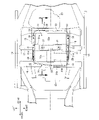
車体中央の左右両側部には前後方向に延びる左右一対のサイドシル14が配置されるとともに、左右のサイドシル14の車幅方向内側には前後方向に延びる左右一対のフロアフレーム15が配置されており、左右のサイドシル14および左右のフロアフレーム15の前部間が車幅方向に延びる第1フロアクロスメンバ16で接続され、左右のサイドシル14および左右のフロアフレーム15の前後方向中間部間が車幅方向に延びる第2フロアクロスメンバ17で接続される。第1フロアクロスメンバ16および第2フロアクロスメンバ17は前後方向に延びる複数のシートレール18で接続されており、これらのシートレール18にフロントシート19が支持される。
A pair of left and
電動モータ11を駆動するバッテリをバッテリケース20内に収納するバッテリパック21が左右のフロアフレーム15および第2フロアクロスメンバ17の下面に支持される。バッテリパック21の前側には、外部電源に充電ケーブルを介して接続されてバッテリを充電するチャージャ22(あるいは非接触式の充電パッド)が配置され、バッテリパック21の後側には、エンジン12を駆動する燃料を貯留する燃料タンク23が配置される。
A
図2~図7に示すように、バッテリケース20は、上向きに開放する金属(アルミニウム)ダイキャスト製のケース本体31と、下向きに開放する金属(アルミニウム)ダイキャスト製のカバー32とを、それらの外周部において複数のボルト33で上下方向に結合して構成される。ケース本体31の底部には8個のバッテリモジュール34が搭載され、その上部にバッテリ制御装置、ジャンクションボード、セル電圧センサ等の電装部品35が配置される。
As shown in FIGS. 2 to 7, the
浅い容器状のケース本体31は、略平坦なケース底壁31aと、ケース底壁31aの外周から起立するケース前壁31b、ケース後壁31cおよび左右のケース側壁31dと、左右のケース側壁31dを車幅方向に接続するクロスメンバ31eとを備える。本実施の形態のクロスメンバ31eは、ケース底壁31aから起立する多数のリブの集合体であるが(図5参照)、その構造は任意である。ケース本体31のクロスメンバ31e上には左右一対の円筒状の第1固定部31fが形成され、また左右のケース側壁31dの車幅方向の外面には、それぞれ前後一対の円筒状の第2固定部31gがケース本体31と一体に形成される。前後一対の第2固定部31gは、ケース側壁31dに対して平行に延びるL字状断面の連結壁31hで接続される。その結果、ケース側壁31d、一対の第2固定部31gおよび連結壁31hに囲まれるように下向きに開放する空間が形成され、この空間内にケース側壁31dおよび連結壁31hを接続する複数枚のリブ31iが形成される。
A shallow container-
バッテリケース20のカバー32は、ケース本体31のクロスメンバ31eに対応する位置に下向きに窪む溝状の凹部32aが形成され、この凹部32a上にケース本体31の一対の第1固定部31fに重なる一対のボルト孔32bが形成され、またカバー32の左右の車幅方向外壁にケース本体31の一対の第2固定部31gに重なる一対のボルト孔32cが形成される。カバー32の前部には電装部品35を収納する隆起部32d,32eが上向きに突設される。
The
車体フロア36の下面に固定された第2フロアクロスメンバ17は、上下方向視でケース本体31のクロスメンバ31eおよびカバー32の凹部32aに重なっている(図3参照)。
The second
このように構成されたバッテリケース20は、ケース本体31の左右2個の第1固定部31fおよびカバー32の左右2個のボルト孔32bを下から上に貫通する2本のボルト37を第1フロアクロスメンバ16の上面に設けた2個ナット38に螺合するとともに、ケース本体31の左右各2個の第2固定部31gおよびカバー32の左右各2個のボルト孔32cを下から上に貫通する各2本のボルト39を左右のフロアフレーム15の上面に設けた各2個ナット40に螺合することで、車体フロア36の下面に固定される。
The
次に、上記構成を備えた本発明の実施の形態の作用を説明する。 Next, the operation of the embodiment of the present invention having the above configuration will be described.
ケース本体31およびカバー32よりなるバッテリケース20は金属ダイキャスト製であるため、その第1、第2固定部31f,31gをケース本体31と一体に形成して部品点数や重量を削減できるだけでなく、ケース本体31にクロスメンバ31eを一体に形成することで、部品点数や重量の増加を最小限に抑えながらケース本体31の強度を増加させて耐側面衝突性能を高めることができる。
Since the
すなわち、フロアフレーム15に対向するバッテリケース20のケース本体31のケース側壁31dには、前後2個の第2固定部31gと、ケース側壁31dに対向する面形状に形成されて2個の第2固定部31gを前後方向に連結する連結壁31hとが一体に形成されるので、車両が側面衝突して衝突荷重がフロアフレーム15からバッテリケース20のケース本体31に入力したとき、2個の第2固定部31g、連結壁31hおよびケース側壁31dに囲まれた空間が潰れることで衝突エネルギーを効果的に吸収することができる。
That is, on the
このとき、第2固定部31gの車幅方向外端はフロアフレーム15の車幅方向外端よりも車幅方向内側に位置するので、側面衝突の衝突荷重をフロアフレーム15で優先的に支持し、受けきれなかった衝突荷重をバッテリケース20で受けることで、バッテリケース20の損傷を最小限に抑えることができる。
At this time, the outer end of the
また第2固定部31gおよび連結壁31hは金属ダイキャスト製のケース本体31と一体に形成されるので、部品点数の削減が可能になるだけでなく、第2固定部31gおよび連結壁31hでケース本体31の剛性が高められる。しかもケース本体31は2個の第2固定部31g間にケース側壁31dおよび連結壁31hを車幅方向に連結するリブ31iを備えるので、第2固定部31gおよび連結壁31hをリブ31iで補強して耐側面衝突性能を一層高めることができる。
In addition, since the
さらにケース本体31のケース側壁31dから車幅方向外側に突出する第2固定部31gがフロアフレーム15にボルト39およびナット40で固定されるので、側面衝突の衝突荷重がフロアフレーム15からケース本体31のクロスメンバ31eに直接的に伝達されて支持されることで、フロアフレーム15の強度を下げて軽量化を図っても耐側面衝突性能を確保することができ、またバッテリケース20のカバー32はケース本体31のクロスメンバ31eに向かって下向きに窪む凹部32aが形成され、この凹部32aと車体の第2フロアクロスメンバ17とは上下方向視でオーバーラップするので、第2フロアクロスメンバ17との干渉を回避しながらバッテリケース20を高い位置に配置し、車両の最低地上高を確保することができる。
Furthermore, since the
しかもバッテリケース20のカバー32の上面には、バッテリ制御装置、ジャンクションボード、セル電圧センサ等の電装部品35を収納する隆起部32d,32eが形成されるが、この隆起部32d,32eは上下方向視で第1フロアクロスメンバ16および第2フロアクロスメンバ17間に配置されるので、第1、第2フロアクロスメンバ16,17との干渉を回避しながら隆起部32d,32eを有するバッテリケース20を車体に搭載することができる。
Moreover, on the upper surface of the
またバッテリケース20のケース後壁31cは燃料タンク23の前端部よりも前方に位置するので、バッテリケース20が後方に突出しないようにしてリヤシートの居住性を確保することができる。
Further, since the case
以上、本発明の実施の形態を説明したが、本発明はその要旨を逸脱しない範囲で種々の設計変更を行うことが可能である。 Although the embodiments of the present invention have been described above, the present invention can be modified in various ways without departing from the gist of the invention.
例えば、燃料タンク23の位置にリヤサブフレームを設け、ケース本体31のケース後壁31cをリヤサブフレームの前端部よりも前方に位置させても良い。
For example, a rear subframe may be provided at the position of the
また実施の形態ではバッテリケース20のケース本体31およびカバー32の両方が金属ダイキャスト製であるが、カバー32は必ずしも金属ダイキャスト製である必要ではない。
In the embodiment, both the
Claims (4)
前記車体は、左右のサイドシル(14)の車幅方向内側で車体フロア(36)の下方に前後方向に延びるように配置される左右のフロアフレーム(15)と、前記左右のフロアフレーム(15)を車幅方向に接続する前側の第1フロアクロスメンバ(16)および後側の第2フロアクロスメンバ(17)とを備え、
前記ケース本体(31)は金属ダイキャスト製であって、ケース底壁(31a)から上方に隆起して車幅方向に延びるクロスメンバ(31e)が一体に形成され、前記クロスメンバ(31e)に設けられた第1固定部(31f)は前記第2フロアクロスメンバ(17)に固定され、前記バッテリパック(21)を前記フロアフレーム(15)に固定するための第2固定部(31g)が、ケース側壁(31d)から車幅方向外方に突出するようにして前記ケース本体(31)に一体に形成され、
前記カバー(32)は前記クロスメンバ(31e)に向かって窪む凹部(32a)が形成され、上下方向視で前記凹部(32a)と前記第2フロアクロスメンバ(17)とは少なくとも一部でオーバーラップすることを特徴とするバッテリパックの配置構造。 A battery pack arrangement structure in which a battery pack (21) in which a battery (34) for driving an electric vehicle is housed in a case body (31) and a cover (32) is arranged in a lower portion of a vehicle body,
The vehicle body includes left and right floor frames (15) arranged to extend in the longitudinal direction below a vehicle body floor (36) inside the left and right side sills (14) in the vehicle width direction, and the left and right floor frames (15). a front first floor cross member (16) and a rear second floor cross member (17) connecting the
The case body (31) is made of die-cast metal, and is integrally formed with a cross member (31e) that protrudes upward from the case bottom wall (31a) and extends in the vehicle width direction. A first fixing portion (31f) provided is fixed to the second floor cross member (17), and a second fixing portion (31g) for fixing the battery pack (21) to the floor frame (15) is provided. , formed integrally with the case body (31) so as to protrude outward in the vehicle width direction from the case side wall (31d),
The cover (32) is formed with a recess (32a) recessed toward the cross member (31e), and the recess (32a) and the second floor cross member (17) are at least partially An arrangement structure of battery packs characterized by overlapping.
前記車体は、前後方向に延びる左右のフロアフレーム(15)と、前記左右のフロアフレーム(15)を車幅方向に接続する前側の第1フロアクロスメンバ(16)および後側の第2フロアクロスメンバ(17)とを備え、
前記ケース本体(31)は金属ダイキャスト製であって、ケース底壁(31a)から上方に隆起して車幅方向に延びるクロスメンバ(31e)が一体に形成され、前記クロスメンバ(31e)に設けられた第1固定部(31f)は前記第2フロアクロスメンバ(17)に固定され、ケース側壁(31d)から車幅方向外側に突出して前記フロアフレーム(15)に固定される第2固定部(31g)が前記ケース本体(31)に一体に形成され、
前記カバー(32)は前記クロスメンバ(31e)に向かって窪む凹部(32a)が形成され、上下方向視で前記凹部(32a)と前記第2フロアクロスメンバ(17)とは少なくとも一部でオーバーラップし、
前後一対の前記第2固定部(31g)と、それらの第2固定部(31g)を連結するようにしてケース側壁(31d)に沿って延びるL字状断面の連結壁(31h)とで、前記ケース側壁(31d)の外面に下向きに解放する空間が形成されることを特徴とするバッテリパックの配置構造。 A battery pack arrangement structure in which a battery pack (21) in which a battery (34) for driving an electric vehicle is housed in a case body (31) and a cover (32) is arranged in a lower portion of a vehicle body,
The vehicle body includes left and right floor frames (15) extending in the longitudinal direction, a front first floor cross member (16) connecting the left and right floor frames (15) in the vehicle width direction, and a rear second floor cross member (16). a member (17);
The case body (31) is made of die-cast metal, and is integrally formed with a cross member (31e) that protrudes upward from the case bottom wall (31a) and extends in the vehicle width direction. The provided first fixing portion (31f) is fixed to the second floor cross member (17), protrudes outward in the vehicle width direction from the case side wall (31d), and is fixed to the floor frame (15). A portion (31g) is formed integrally with the case body (31),
The cover (32) is formed with a recess (32a) recessed toward the cross member (31e), and the recess (32a) and the second floor cross member (17) are at least partially overlap and
A pair of front and rear second fixing portions (31g) and a connecting wall (31h) having an L-shaped cross section extending along the side wall (31d) of the case so as to connect the second fixing portions (31g), An arrangement structure of a battery pack, wherein a downward opening space is formed in the outer surface of the case side wall (31d).
Applications Claiming Priority (3)
| Application Number | Priority Date | Filing Date | Title |
|---|---|---|---|
| JP2018158938 | 2018-08-28 | ||
| JP2018158938 | 2018-08-28 | ||
| PCT/JP2019/026641 WO2020044792A1 (en) | 2018-08-28 | 2019-07-04 | Battery pack arrangement structure |
Publications (2)
| Publication Number | Publication Date |
|---|---|
| JPWO2020044792A1 JPWO2020044792A1 (en) | 2021-08-26 |
| JP7126552B2 true JP7126552B2 (en) | 2022-08-26 |
Family
ID=69644173
Family Applications (1)
| Application Number | Title | Priority Date | Filing Date |
|---|---|---|---|
| JP2020540115A Active JP7126552B2 (en) | 2018-08-28 | 2019-07-04 | Battery pack layout structure |
Country Status (5)
| Country | Link |
|---|---|
| US (1) | US11685249B2 (en) |
| JP (1) | JP7126552B2 (en) |
| CN (1) | CN112638681B (en) |
| DE (1) | DE112019004338T5 (en) |
| WO (1) | WO2020044792A1 (en) |
Families Citing this family (28)
| Publication number | Priority date | Publication date | Assignee | Title |
|---|---|---|---|---|
| US11938825B2 (en) * | 2017-11-07 | 2024-03-26 | Eaton Intelligent Power Limited | System and method of a mobile electrical system |
| WO2020044792A1 (en) * | 2018-08-28 | 2020-03-05 | 本田技研工業株式会社 | Battery pack arrangement structure |
| JP7099310B2 (en) * | 2018-12-26 | 2022-07-12 | 株式会社オートネットワーク技術研究所 | Vehicle-mounted structure of power storage device |
| CN113809461B (en) | 2020-05-28 | 2022-12-09 | 比亚迪股份有限公司 | Battery pack case, battery pack and vehicle |
| CN113858931A (en) * | 2020-06-30 | 2021-12-31 | 广州汽车集团股份有限公司 | Car and power battery mounting structure thereof |
| DE102020117317B3 (en) * | 2020-07-01 | 2021-11-18 | Dr. Ing. H.C. F. Porsche Aktiengesellschaft | Rocker frame assembly and a vehicle body assembly with such a rocker frame assembly |
| DE102020127911A1 (en) | 2020-10-23 | 2022-04-28 | Dr. Ing. H.C. F. Porsche Aktiengesellschaft | Method of mounting a battery control unit to a battery case |
| JP7372228B2 (en) * | 2020-11-25 | 2023-10-31 | 本田技研工業株式会社 | Vehicles equipped with battery packs |
| US11926226B2 (en) * | 2020-12-10 | 2024-03-12 | Hyundai Motor Company | Vehicle body |
| US11713081B2 (en) | 2020-12-10 | 2023-08-01 | Hyundai Motor Company | Vehicle body |
| US11794813B2 (en) | 2020-12-10 | 2023-10-24 | Hyundai Motor Company | Vehicle body and vehicle |
| KR20220082490A (en) | 2020-12-10 | 2022-06-17 | 현대자동차주식회사 | Body of vehicle |
| JP7533247B2 (en) * | 2021-01-28 | 2024-08-14 | トヨタ自動車株式会社 | Power storage device |
| DE102021103988A1 (en) * | 2021-02-19 | 2022-08-25 | Dr. Ing. H.C. F. Porsche Aktiengesellschaft | Motor vehicle floor and motor vehicle with a motor vehicle floor |
| JP2023002334A (en) * | 2021-06-22 | 2023-01-10 | トヨタ自動車株式会社 | Vehicle seat support structure |
| JP7452498B2 (en) * | 2021-06-22 | 2024-03-19 | トヨタ自動車株式会社 | Vehicle front structure |
| KR102893182B1 (en) * | 2021-08-27 | 2025-11-28 | 컨템포러리 엠퍼렉스 테크놀로지 (홍콩) 리미티드 | Battery box, battery, bracket and electrical device |
| JP2023046924A (en) * | 2021-09-24 | 2023-04-05 | 本田技研工業株式会社 | Vehicle body lower part structure |
| JP7588569B2 (en) * | 2021-09-24 | 2024-11-22 | 本田技研工業株式会社 | Underbody structure |
| KR102897377B1 (en) * | 2021-11-09 | 2025-12-08 | 에스케이온 주식회사 | ModulelessBattery Pack |
| CN114179918A (en) * | 2021-11-29 | 2022-03-15 | 浙江吉利控股集团有限公司 | Vehicle body framework |
| JP7700702B2 (en) * | 2022-02-24 | 2025-07-01 | マツダ株式会社 | Rear body structure |
| CN115214777B (en) * | 2022-03-31 | 2023-11-24 | 长城汽车股份有限公司 | Vehicle chassis structure and vehicle |
| KR20240091166A (en) * | 2022-06-29 | 2024-06-21 | 컨템포러리 엠퍼렉스 테크놀로지 씨오., 리미티드 | Case, battery and electrical devices |
| FR3137796A1 (en) * | 2022-07-07 | 2024-01-12 | Psa Automobiles Sa | TRACTION BATTERY COMPRISING AT LEAST ONE FUSE FIXING MEANS BREAK IN CASE OF SIDE SHOCK, VEHICLE AND METHOD BASED ON SUCH A BATTERY |
| CN222005203U (en) * | 2024-01-25 | 2024-11-15 | 宁德时代(上海)智能科技有限公司 | Vehicle body and vehicle |
| FR3162679A1 (en) * | 2024-05-28 | 2025-12-05 | Stellantis Auto Sas | ELECTRIC OR HYBRID MOTOR VEHICLE WITH A CHARGING RECEIVER |
| WO2026069591A1 (en) * | 2024-09-27 | 2026-04-02 | 株式会社Subaru | Vehicle |
Citations (3)
| Publication number | Priority date | Publication date | Assignee | Title |
|---|---|---|---|---|
| JP2011121483A (en) | 2009-12-11 | 2011-06-23 | Mitsubishi Motors Corp | Battery unit mounting structure for vehicle |
| JP2016220475A (en) | 2015-05-25 | 2016-12-22 | トヨタ自動車株式会社 | Electric vehicle and battery pack |
| JP2017226353A (en) | 2016-06-23 | 2017-12-28 | 本田技研工業株式会社 | Lower structure of the car body |
Family Cites Families (21)
| Publication number | Priority date | Publication date | Assignee | Title |
|---|---|---|---|---|
| JP3350189B2 (en) * | 1993-04-30 | 2002-11-25 | 本田技研工業株式会社 | Battery box device for electric vehicles |
| JP4858183B2 (en) * | 2007-01-22 | 2012-01-18 | 日産自動車株式会社 | Lower body structure |
| US9083029B2 (en) * | 2009-12-23 | 2015-07-14 | Samsung Sdi Co., Ltd. | Battery pack |
| JP2012001060A (en) * | 2010-06-15 | 2012-01-05 | Calsonic Kansei Corp | Heat exchanger for vehicle |
| WO2012078721A2 (en) * | 2010-12-07 | 2012-06-14 | Allison Transmission, Inc. | Energy storage system for hybrid electric vehicle |
| WO2012086297A1 (en) * | 2010-12-24 | 2012-06-28 | 本田技研工業株式会社 | Automobile body structure |
| JP5364767B2 (en) * | 2011-09-26 | 2013-12-11 | 富士重工業株式会社 | Battery support structure for vehicle |
| JP5814068B2 (en) * | 2011-10-07 | 2015-11-17 | オートモーティブエナジーサプライ株式会社 | Battery pack for driving electric vehicles |
| JP5734453B2 (en) * | 2011-11-14 | 2015-06-17 | 本田技研工業株式会社 | Battery built-in structure |
| WO2013084936A1 (en) * | 2011-12-09 | 2013-06-13 | 本田技研工業株式会社 | Vehicle-mounted battery pack structure |
| JP5984052B2 (en) * | 2012-07-17 | 2016-09-06 | 三菱自動車工業株式会社 | Battery pack positioning pin bracket |
| JP2014024359A (en) | 2012-07-24 | 2014-02-06 | Suzuki Motor Corp | Vehicular battery pack |
| JP5899182B2 (en) * | 2013-10-23 | 2016-04-06 | 本田技研工業株式会社 | Electric vehicle |
| JP5829706B2 (en) * | 2014-02-25 | 2015-12-09 | 富士重工業株式会社 | Automotive battery |
| JP6144658B2 (en) * | 2014-10-01 | 2017-06-07 | トヨタ自動車株式会社 | In-vehicle power supply |
| JP6344270B2 (en) * | 2015-03-06 | 2018-06-20 | トヨタ自動車株式会社 | Battery unit mounting structure |
| JP6514248B2 (en) * | 2017-02-17 | 2019-05-15 | 本田技研工業株式会社 | Substructure of car body |
| US10971777B2 (en) * | 2017-04-11 | 2021-04-06 | Ford Global Technologies, Llc | Traction battery support assembly and method |
| JP6976116B2 (en) * | 2017-09-21 | 2021-12-08 | 株式会社ブルーエナジー | Power storage device |
| WO2020044792A1 (en) * | 2018-08-28 | 2020-03-05 | 本田技研工業株式会社 | Battery pack arrangement structure |
| US11364956B2 (en) * | 2019-12-11 | 2022-06-21 | Ford Global Technologies, Llc | Motor vehicle floor assembly with recesses for electrical lines and electrical modules |
-
2019
- 2019-07-04 WO PCT/JP2019/026641 patent/WO2020044792A1/en not_active Ceased
- 2019-07-04 US US17/271,335 patent/US11685249B2/en active Active
- 2019-07-04 CN CN201980056617.6A patent/CN112638681B/en active Active
- 2019-07-04 DE DE112019004338.2T patent/DE112019004338T5/en active Pending
- 2019-07-04 JP JP2020540115A patent/JP7126552B2/en active Active
Patent Citations (3)
| Publication number | Priority date | Publication date | Assignee | Title |
|---|---|---|---|---|
| JP2011121483A (en) | 2009-12-11 | 2011-06-23 | Mitsubishi Motors Corp | Battery unit mounting structure for vehicle |
| JP2016220475A (en) | 2015-05-25 | 2016-12-22 | トヨタ自動車株式会社 | Electric vehicle and battery pack |
| JP2017226353A (en) | 2016-06-23 | 2017-12-28 | 本田技研工業株式会社 | Lower structure of the car body |
Also Published As
| Publication number | Publication date |
|---|---|
| CN112638681B (en) | 2023-09-19 |
| CN112638681A (en) | 2021-04-09 |
| JPWO2020044792A1 (en) | 2021-08-26 |
| WO2020044792A1 (en) | 2020-03-05 |
| US11685249B2 (en) | 2023-06-27 |
| DE112019004338T5 (en) | 2021-05-12 |
| US20210339617A1 (en) | 2021-11-04 |
Similar Documents
| Publication | Publication Date | Title |
|---|---|---|
| JP7126552B2 (en) | Battery pack layout structure | |
| US11034248B2 (en) | Battery case fixing structure | |
| KR102772122B1 (en) | The undercarriage of a car | |
| US10632827B2 (en) | Vehicle lower portion structure | |
| JP7476080B2 (en) | Body structure | |
| JP4386131B2 (en) | Electric car | |
| JP5472361B2 (en) | Vehicle battery mounting structure | |
| US8813888B2 (en) | Vehicle body rear structure | |
| US12065030B2 (en) | Rear vehicle-body structure | |
| CN111516620A (en) | vehicle | |
| JP6997525B2 (en) | In-vehicle battery | |
| US20140117198A1 (en) | Supporting structure for vehicle control unit | |
| CN111465521A (en) | Motor vehicle with drive battery | |
| JP2017001441A (en) | Mounting structure for vehicle battery pack | |
| US20230264752A1 (en) | Rear vehicle-body structure | |
| CN114644055A (en) | Cowl structure for vehicle | |
| JP2020196432A (en) | Lower part vehicle body structure of electric vehicle | |
| US12344317B2 (en) | Rear vehicle body structure | |
| JP6284041B2 (en) | Vehicle battery mounting structure | |
| JP6769903B2 (en) | In-vehicle battery | |
| JP2016068850A (en) | Battery drive battery mounting structure | |
| JP2023046934A (en) | Vehicle body lower part structure | |
| JP2019059478A (en) | Attachment structure of vehicle battery pack | |
| CN116890929B (en) | Vehicle structure with storage battery | |
| US12371104B2 (en) | Vehicle-body front structure |
Legal Events
| Date | Code | Title | Description |
|---|---|---|---|
| A529 | Written submission of copy of amendment under article 34 pct |
Free format text: JAPANESE INTERMEDIATE CODE: A5211 Effective date: 20201119 |
|
| A621 | Written request for application examination |
Free format text: JAPANESE INTERMEDIATE CODE: A621 Effective date: 20201130 |
|
| A131 | Notification of reasons for refusal |
Free format text: JAPANESE INTERMEDIATE CODE: A131 Effective date: 20220112 |
|
| A521 | Request for written amendment filed |
Free format text: JAPANESE INTERMEDIATE CODE: A523 Effective date: 20220228 |
|
| TRDD | Decision of grant or rejection written | ||
| A01 | Written decision to grant a patent or to grant a registration (utility model) |
Free format text: JAPANESE INTERMEDIATE CODE: A01 Effective date: 20220803 |
|
| A61 | First payment of annual fees (during grant procedure) |
Free format text: JAPANESE INTERMEDIATE CODE: A61 Effective date: 20220816 |
|
| R150 | Certificate of patent or registration of utility model |
Ref document number: 7126552 Country of ref document: JP Free format text: JAPANESE INTERMEDIATE CODE: R150 |