EP4220039A1 - Refrigeration system and refrigeration appliance having same - Google Patents
Refrigeration system and refrigeration appliance having same Download PDFInfo
- Publication number
- EP4220039A1 EP4220039A1 EP21884555.0A EP21884555A EP4220039A1 EP 4220039 A1 EP4220039 A1 EP 4220039A1 EP 21884555 A EP21884555 A EP 21884555A EP 4220039 A1 EP4220039 A1 EP 4220039A1
- Authority
- EP
- European Patent Office
- Prior art keywords
- pipe
- sectional area
- cross
- channel
- expanded
- Prior art date
- Legal status (The legal status is an assumption and is not a legal conclusion. Google has not performed a legal analysis and makes no representation as to the accuracy of the status listed.)
- Pending
Links
- 238000005057 refrigeration Methods 0.000 title description 3
- 230000007704 transition Effects 0.000 claims abstract description 82
- 239000003507 refrigerant Substances 0.000 claims description 57
- 238000001035 drying Methods 0.000 claims description 16
- RYGMFSIKBFXOCR-UHFFFAOYSA-N Copper Chemical compound [Cu] RYGMFSIKBFXOCR-UHFFFAOYSA-N 0.000 claims description 10
- 229910000831 Steel Inorganic materials 0.000 claims description 10
- 229910052802 copper Inorganic materials 0.000 claims description 10
- 239000010949 copper Substances 0.000 claims description 10
- 239000010959 steel Substances 0.000 claims description 10
- 230000007423 decrease Effects 0.000 claims description 5
- 230000007246 mechanism Effects 0.000 description 19
- 230000006872 improvement Effects 0.000 description 14
- 230000010349 pulsation Effects 0.000 description 7
- 230000005540 biological transmission Effects 0.000 description 6
- 238000003466 welding Methods 0.000 description 6
- 239000007789 gas Substances 0.000 description 5
- 230000000694 effects Effects 0.000 description 4
- 238000007789 sealing Methods 0.000 description 4
- 230000003321 amplification Effects 0.000 description 3
- 230000008859 change Effects 0.000 description 3
- 239000007788 liquid Substances 0.000 description 3
- 238000003199 nucleic acid amplification method Methods 0.000 description 3
- 239000012071 phase Substances 0.000 description 3
- 230000002238 attenuated effect Effects 0.000 description 2
- 238000009499 grossing Methods 0.000 description 2
- 238000003780 insertion Methods 0.000 description 2
- 230000037431 insertion Effects 0.000 description 2
- 239000007791 liquid phase Substances 0.000 description 2
- 239000000463 material Substances 0.000 description 2
- 239000002184 metal Substances 0.000 description 2
- 229910052751 metal Inorganic materials 0.000 description 2
- 238000000034 method Methods 0.000 description 2
- 230000008569 process Effects 0.000 description 2
- 230000009467 reduction Effects 0.000 description 2
- 230000009471 action Effects 0.000 description 1
- 230000002708 enhancing effect Effects 0.000 description 1
- 238000001704 evaporation Methods 0.000 description 1
- 230000008020 evaporation Effects 0.000 description 1
- 239000007792 gaseous phase Substances 0.000 description 1
- 238000003754 machining Methods 0.000 description 1
- 238000012986 modification Methods 0.000 description 1
- 230000004048 modification Effects 0.000 description 1
- 229920006395 saturated elastomer Polymers 0.000 description 1
- 239000011555 saturated liquid Substances 0.000 description 1
- 239000013526 supercooled liquid Substances 0.000 description 1
- 238000009834 vaporization Methods 0.000 description 1
- 230000008016 vaporization Effects 0.000 description 1
Images


Classifications
-
- F—MECHANICAL ENGINEERING; LIGHTING; HEATING; WEAPONS; BLASTING
- F25—REFRIGERATION OR COOLING; COMBINED HEATING AND REFRIGERATION SYSTEMS; HEAT PUMP SYSTEMS; MANUFACTURE OR STORAGE OF ICE; LIQUEFACTION SOLIDIFICATION OF GASES
- F25B—REFRIGERATION MACHINES, PLANTS OR SYSTEMS; COMBINED HEATING AND REFRIGERATION SYSTEMS; HEAT PUMP SYSTEMS
- F25B39/00—Evaporators; Condensers
-
- F—MECHANICAL ENGINEERING; LIGHTING; HEATING; WEAPONS; BLASTING
- F04—POSITIVE - DISPLACEMENT MACHINES FOR LIQUIDS; PUMPS FOR LIQUIDS OR ELASTIC FLUIDS
- F04B—POSITIVE-DISPLACEMENT MACHINES FOR LIQUIDS; PUMPS
- F04B39/00—Component parts, details, or accessories, of pumps or pumping systems specially adapted for elastic fluids, not otherwise provided for in, or of interest apart from, groups F04B25/00 - F04B37/00
- F04B39/0027—Pulsation and noise damping means
- F04B39/0055—Pulsation and noise damping means with a special shape of fluid passage, e.g. bends, throttles, diameter changes, pipes
-
- F—MECHANICAL ENGINEERING; LIGHTING; HEATING; WEAPONS; BLASTING
- F04—POSITIVE - DISPLACEMENT MACHINES FOR LIQUIDS; PUMPS FOR LIQUIDS OR ELASTIC FLUIDS
- F04B—POSITIVE-DISPLACEMENT MACHINES FOR LIQUIDS; PUMPS
- F04B39/00—Component parts, details, or accessories, of pumps or pumping systems specially adapted for elastic fluids, not otherwise provided for in, or of interest apart from, groups F04B25/00 - F04B37/00
- F04B39/0027—Pulsation and noise damping means
- F04B39/0055—Pulsation and noise damping means with a special shape of fluid passage, e.g. bends, throttles, diameter changes, pipes
- F04B39/0072—Pulsation and noise damping means with a special shape of fluid passage, e.g. bends, throttles, diameter changes, pipes characterised by assembly or mounting
-
- F—MECHANICAL ENGINEERING; LIGHTING; HEATING; WEAPONS; BLASTING
- F25—REFRIGERATION OR COOLING; COMBINED HEATING AND REFRIGERATION SYSTEMS; HEAT PUMP SYSTEMS; MANUFACTURE OR STORAGE OF ICE; LIQUEFACTION SOLIDIFICATION OF GASES
- F25B—REFRIGERATION MACHINES, PLANTS OR SYSTEMS; COMBINED HEATING AND REFRIGERATION SYSTEMS; HEAT PUMP SYSTEMS
- F25B41/00—Fluid-circulation arrangements
- F25B41/30—Expansion means; Dispositions thereof
- F25B41/37—Capillary tubes
-
- F—MECHANICAL ENGINEERING; LIGHTING; HEATING; WEAPONS; BLASTING
- F25—REFRIGERATION OR COOLING; COMBINED HEATING AND REFRIGERATION SYSTEMS; HEAT PUMP SYSTEMS; MANUFACTURE OR STORAGE OF ICE; LIQUEFACTION SOLIDIFICATION OF GASES
- F25B—REFRIGERATION MACHINES, PLANTS OR SYSTEMS; COMBINED HEATING AND REFRIGERATION SYSTEMS; HEAT PUMP SYSTEMS
- F25B41/00—Fluid-circulation arrangements
- F25B41/40—Fluid line arrangements
Definitions
- the present invention relates to a refrigerating system, and a refrigerating appliance having the same, and belongs to the technical field of household appliances.
- a capillary In a refrigerating system in currently commonly-used refrigerating appliances such as refrigerators and freezers, a capillary is usually used between a condenser and an evaporator for throttling and depressurization.
- a high-voltage medium-temperature liquid-phase refrigerant enters the capillary; under the action of a friction force of a wall surface of the capillary, a resistance received by the refrigerant increases gradually, the pressure and temperature of the refrigerant reduces gradually, the refrigerant finally reaches a two-phase refrigerant state under an evaporation pressure at an outlet of the capillary, and enters the evaporator at a high speed.
- the refrigerant after spurting from the capillary at a high speed, changes in phase and generates a lot of bubbles; as the pressure reduces constantly, the bubbles become larger until they break, thereby generating a spurting noise; the noise may cause the overall noise of the refrigerator to increase so that the user's experience is extremely poor.
- the present utility model provides a refrigerating system, and a refrigerating appliance having the same.
- an embodiment of the present utility model provides a refrigerating system
- the refrigerating system includes a compressor, a condenser, a throttle pipeline, a transition pipe, and an evaporator connected in series in sequence
- the throttle pipeline comprises a capillary body and at least two expanded pipes
- the expanded pipe comprises a main body pipe
- the number of second equal-diameter pipes is set to two or more segments that are sequentially connected in series from front to rear, the cross-sectional area of the channels in the segments increasing gradually.
- the intermediate expanded pipe is arranged such that a front end of the main body pipe of the intermediate expanded pipe is connected with a rear end of a preceding capillary segment to form a vertical stepped surface, and a rear end of the main body pipe of the intermediate expanded pipe is connected with a front end of a following capillary segment to form a vertical stepped surface;
- the last expanded pipe is arranged such that the front end of main body pipe of the last expanded pipe is connected with the rear end of the last capillary segment to form a vertical stepped surface, and the rear end of the main body pipe of the last expanded pipe is connected with the front end of the transition pipe.
- the intermediate expanded pipe is arranged such that the rear end of the preceding capillary segment passes through the front end of the main body pipe of the intermediate expanded pipe and extends rearward into the intermediate expanded pipe, and such that the front end of the following capillary segment passes through the rear end of the main body pipe of the intermediate expanded pipe and extends forward into the intermediate expanded pipe;
- the last expanded pipe is arranged such that the rear end of the last capillary segment passes through the front end of the main body pipe of the last expanded pipe and extends rearward into the last expanded pipe, the rear end of the main body pipe of the last expanded pipe being connected with the front end of the transition pipe.
- the expanded pipe further comprises a flared pipe connected in series between the front end of the main body pipe of the expanded pipe and the rear end of a preceding capillary segment, and a cross-sectional area of a channel in the flared pipe gradually increases from the cross-sectional area of the channel in the capillary body from front to rear to the cross-sectional area of the channel in the first equal-diameter pipe.
- the intermediate expanded pipe further comprises a closure pipe connected in series between the rear end of the main body pipe and the front end of the following capillary segment, and a cross-sectional area of a channel in the closure pipe gradually decreases from the cross-sectional area of the channel in the main body pipe from the front to the rear to the cross-sectional area of the channel in the capillary body; the rear end of the last expanded pipe is connected with the front end of the transition pipe.
- the cross-sectional area of the channel in the capillary body is constant, and the cross-sectional area of the channel in the main body pipe is 4 to 75 times the cross-sectional area of the channel in the capillary body.
- the transition pipe comprises:
- the transition pipe is provided as a flared transition pipe, and a cross-sectional area of the channel in the flared transition pipe gradually increases from the cross-sectional area of the channel in the main body pipe of the last expanded pipe at the rear end from front to rear to the cross-sectional area of the channel in the refrigerant pipe of the evaporator.
- the throttle pipeline on the whole, is provided as a rigid pipe integrally formed of copper or steel,
- a section of the throttle pipeline extending from rear to front from the rear end of the last expanded pipe, at least to the front end of the last intermediate expanded pipe is set as a flexible pipe.
- all the transition pipe or a portion from the front end of the transition pipe is set as the flexible pipe, and integrally formed with the flexible pipe of the throttle pipeline.
- the throttle pipeline is disposed in a sole refrigerant flow path that communicates an egress end of the condenser with an ingress end of the evaporator.
- the egress end of the condenser is provided with a drying filter, and a front end of the throttle pipeline is fixedly fitted with the drying filter; or the egress end of the condenser is sequentially provided with a drying filter and a solenoid valve from the front to the rear, and the front end of the throttle pipeline is fixedly connected to the solenoid valve.
- an embodiment of the present utility model provides a refrigerating appliance includes the refrigerating system.
- the refrigerating system achieves stage-wise attenuation and smoothing of the spurt and pulsation, substantially reduces the problem of the noise caused by the break of bubbles during the spurting, decreases the outward, forward and backward transfer of the spurting pulsation along the pipeline of the refrigerating system, and avoids the noise amplification phenomenon caused by vibration transmission, by disposing the expanded pipes in the middle of and at the rear end of the capillary body, disposing the transition pipe between the last expanded pipe and the refrigerant pipe of the evaporator, and setting the relationship of the magnitude of the cross-sectional areas of the channels in the capillary body, expanded pipes, transition pipe, and the refrigerant pipe of the evaporator.
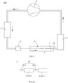
- FIG. 1 through FIG. 3b they illustrate a refrigerating system 100 in a first embodiment of the present utility model.
- the refrigerating system 100 has a flow circuit in which a refrigerant flows in a circulating manner.
- the refrigerating system 100 comprises a compressor 1, a condenser 2, a throttle pipeline 3, a transition pipe 7, and an evaporator 4 connected in series in sequence.
- an exhaust pipe of the compressor 1 is connected to an ingress end of the condenser 2, and a gas return pipe of the compressor 1 is connected to an egress end of the evaporator 4; the throttle pipeline 3 is communicated between an egress end of the condenser 2 and an ingress end of the evaporator 4.
- a circulation process of the refrigerant in the refrigerating system 100 is theoretically roughly as follows: a high-temperature and high-pressure superheated refrigerant gas in the exhaust pipe of the compressor 1 enters the condenser 2 and is condensed into a high-pressure saturated or supercooled liquid which then enters the throttle pipeline 3 for throttling and depressurization, and then flows through the transition pipe 7 into the evaporator 4 for vaporization into a low-temperature and low-pressure refrigerant gas, which returns to the compressor 1 to be recompressed into a high-temperature and high-pressure superheated refrigerant gas, thereby completing the entire circulation process.
- the pipeline structure formed by the throttle pipeline 3, the transition pipe 7 and the ingress end of the refrigerant pipe 41 of the evaporator 4 is improved to solve the problem about the spurting of noise in the prior art.
- the throttle pipeline 3 comprises a capillary body 30 and an expanded pipe 31.
- the capillary body 30 is a capillary pipe in which a channel has a constant cross-sectional area and which is constructed to have a length of more than half of the throttle pipeline 3; a cross-sectional area of a channel in the expanded pipe 31 is greater than the cross-sectional area of the channel in the capillary body 30.
- the throttle pipeline 3 comprises at least two expanded pipes 31 spaced sequentially from front to rear.
- One of the expanded pipes 31 is connected in series between the capillary body 30 and the transition pipe 7, that is, the expanded pipe 31 defines a rear end of the throttle pipeline 3; the remaining expanded pipes 31 are connected in series in the capillary body 30 to divide the capillary body 30 into at least two capillary segments.
- the expanded pipes are distinguished in a way that one expanded pipe 31 connected in series between the capillary body 30 and the transition pipe 7 is defined as the last expanded pipe 31-2, and the remaining expanded pipes 31 connected in series in the capillary body 30 are defined as intermediate expanded pipes 31-1, for ease of understanding and description.
- the number of expanded pipes 31 is at least two
- the number of intermediate expanded pipes 31-1 is at least one.
- the at least one intermediate expanded pipe 31-1 divides the capillary body 30 into at least two capillary segments.
- the capillary body 30 comprises at least two spaced-apart capillary segments, and two adjacent capillary segments are communicated through an intermediate expanded pipe 31-1.
- the throttle pipeline 3 constitutes a pipeline structure of [capillary-- middle expanded pipe 31-1] ⁇ n-capillary-- last expanded pipe 31-2, where n is a positive integer.
- the number of expanded pipes 31 is exemplified as two: one last expanded pipe 31-2, and one intermediate expanded pipe 31-1; wherein the one intermediate expanded pipe 31-1 divides the capillary body 30 into two capillary segments, namely, the capillary 30-1 and the capillary 30-2; the last expanded pipe 31-2 is connected between the last capillary segment (i.e., capillary 30-2) and the transition pipe 7.
- the number of expanded pipes 31 may be three or more, and accordingly, the capillary body 30 is divided into three or more capillary segments.
- the cross-sectional area of the channel in the last expanded pipe 31-2 is smaller than the cross-sectional area of the channel in the transition pipe 7; furthermore, the cross-sectional area of the channel in the transition pipe 7 is smaller than the cross-sectional area of the channel in the refrigerant pipe 41 of the evaporator 4.
- the refrigerating system 100 achieves stage-wise attenuation and smoothing of the spurt and pulsation, substantially reduces the problem of the noise caused by the break of bubbles during the spurting, decreases the outward, forward and backward transfer of the spurting pulsation along the pipeline of the refrigerating system 100, and avoids the noise amplification phenomenon caused by vibration transmission, by disposing the expanded pipes 31 in the middle of and at the rear end of the capillary body 30, disposing the transition pipe 7 between the last expanded pipe 31-2 and the refrigerant pipe 41 of the evaporator 4, and setting the relationship of the magnitude of the cross-sectional areas of the channels in the capillary body 30, expanded pipes 31, transition pipe 7, and the refrigerant pipe 41 of the evaporator 4.
- the cross-sectional area of the channel in each expanded pipe 31 among all the expanded pipes 31 including the last expanded pipe 31-2 is smaller than the cross-sectional area of the channel in the transition pipe 7.
- the cross-sectional area of the channel in the throttle pipeline 3 is smaller than the cross-sectional area of the channel in the transition pipe 7.
- the refrigerant will not spurt at a high rate like a conventional capillary spurting port when the refrigerant enters the middle expanded pipe 31-1, and the refrigerant will not generate a lot of bubbles like the conventional capillary spurting port when the refrigerant flows in the middle expanded pipe 31-1, and the bubbles will break with a small volume and will not generate a large noise;
- the refrigerant mostly spurts upon entering the last expanded pipe 31-2 and the transition pipe 7 from the capillary; since the refrigerant is already partly converted from a liquid phase into a gaseous phase at the preceding middle expanded pipe 31-1, the gas phase in the refrigerant entering the last expanded pipe 31-2 is in a larger proportion as compared with the conventional capillary spurting port; then, the cross-sectional area in the channels in the last expanded pipe 31-2, the transition
- the egress end of the condenser 2 and the ingress end of the evaporator 4 are communicated through a sole refrigerant flow path, and the throttle pipeline 3 is disposed in the sole refrigerant flow path that communicates the egress end of the condenser 2 with the ingress end of the evaporator 4. That is, when the refrigerating system 100 performs refrigeration, the refrigerant in the condenser 2 inevitably needs to enter the evaporator 4 through the throttle pipeline 3.
- the egress end of the condenser 2 is provided with a drying filter 5, and a front end of the throttle pipeline 3 is fixedly fitted with the drying filter 5, that is, the front end of the foremost capillary segment 30-1 is fixedly fitted with the drying filter 5.
- any two expanded pipes 31 may be set in the same shape or different shapes.
- any two expanded pipes 31 may be set in the same shape.
- Each expanded pipe 31 comprises a main body pipe provided as a first equal-diameter pipe with a constant cross-sectional area of the channel in the pipe. More specifically, each expanded pipe 31 is provided as an equal-diameter pipe structure.
- the intermediate expanded pipe 31-1 is arranged such that a front end of the main body pipe of the intermediate expanded pipe 31-1 is connected with a rear end of a preceding capillary segment 30-1 to form a vertical stepped surface, and a rear end of the main body pipe of the intermediate expanded pipe 31-1 is connected with a front end of a following capillary segment 30-2 to form a vertical stepped surface.
- the last expanded pipe 31-2 is arranged such that the front end of main body pipe of the last expanded pipe 31-2 is connected with the rear end of the capillary 30-2 to form a vertical stepped surface, and the rear end of the main body pipe of the last expanded pipe 31-2 is connected with the front end of the transition pipe 7.
- the cross-sectional area of the channel in the main body pipe of each expanded pipe 31 is 4 to 75 times the cross-sectional area of the channel in the capillary body 30.
- the transition pipe 7 comprises an equal-diameter pipe 72, a flared pipe 71, and a flared pipe 73.
- the flared pipe 71 and the flared pipe 73 are connected to a front end and a rear end of the equal-diameter pipe 72, respectively.
- the flared pipe 71 is connected in series between the rear end of the throttle pipeline 3 and the front end of the equal-diameter pipe 72, and is specifically connected in series between the rear end of the main body pipe of the last expanded pipe 31-2 and the front end of the equal-diameter pipe 72.
- the cross-sectional area of a channel in the flared pipe 71 gradually increases from the cross-sectional area of the channel in the main body pipe of the last expanded pipe 31-2 at the rear end from front to rear to the cross-sectional area of the channel in the equal-diameter pipe 72, i.e., the cross-sectional area of the channel in the flared pipe 71 at the front end is equal to the cross-sectional area of the channel in the main body pipe of the last extended pipe 31-2 at the rear end, and the cross-sectional area of the channel in the flared pipe 72 at the rear end is equal to the cross-sectional area of the channel in the equal-diameter pipe 72.
- the flared pipe 73 is connected in series between the rear end of the equal-diameter pipe 72 and the front end of the refrigerant pipe 41 of the evaporator 4.
- the cross-sectional area of a channel in the flared pipe 73 gradually increases from the cross-sectional area of the channel in the equal-diameter pipe 72 from front to rear to the cross-sectional area of the channel in the refrigerant pipe 41 of the evaporator 4.
- the transition pipe 7 may also be provided as a flared transition pipe, and the cross-sectional area of the channel ins the flared transition pipe gradually increases from the cross-sectional area of the channel in the main body pipe of the last expanded pipe 31-2 at the rear end from front to rear to the cross-sectional area of the channel in the refrigerant pipe 41 of the evaporator 4, i.e., the throttle pipeline 3 is connected to the refrigerant pipe 41 of the evaporator 4 via the flared transition pipe.
- both the throttle pipeline 3 and the transition pipe 7 are provided as circular pipes, and the cross sections of the channels in the throttle pipeline 3 and the transition pipe 7 at all positions are circular.
- the shapes of the cross sections of the channels in the throttle pipeline 3 and transition pipe 7 at all positions are not limited to this, and may also be square, hexagonal, elliptical, waist-shaped, or other feasible suitable shapes.
- the size relationship of the cross-sectional area of the channels in the respective pipes described above corresponds to the size relationship of inner diameters of the respective pipes.
- the cross-sectional area of the channel in the throttle pipeline 3 is smaller than the cross-sectional area of the channel in the transition pipe 7, the inner diameter of the throttle pipeline 3 is correspondingly smaller than the inner diameter of the transition pipe 7.
- an inner wall of the flared pipe 71 may be set as an inclined surface or an inwardly-convex arc surface or an outwardly-recessed arc surface in a front-rear direction
- an inner wall of the flared pipe 73 may also be set as an inclined surface or an inwardly-convex arc surface or an outwardly-recessed arc surface in a front-rear direction
- an inner wall of the flared transition pipe in a variant embodiment may be also set as an inclined surface in a front-rear direction or an inwardly-convex arc surface or an outwardly-recessed arc surface.
- the throttle pipeline 3 is arranged such that one section of the pipeline is a flexible pipe, and the remaining section of the pipeline is a rigid pipe integrally formed of copper or steel.
- a rear section of the throttle pipeline 3 is a flexible pipe and a front section of the throttle pipeline 3 is a rigid pipe integrally formed of copper or steel.
- a section extending from rear to front from the rear end (as indicated by C8 in FIG. 2b ) of the last expanded pipe 31-2, at least to the front end (as indicated by C2 in FIG. 2b ) of the last intermediate expanded pipe 31-1 is set as the flexible pipe, i.e., a section of the throttle pipeline 3 between the position indicated by C2 and the position indicated by C8 in FIG. 2b is the flexible pipe, and the section of the throttle pipeline 3 before the position indicated by C2 is the rigid pipe.
- the vibration of the break of the bubbles generated in the spurting of the last expanded pipe 31 acts on the wall of the flexible pipe and may be absorbed by the flexible pipe, thereby ensuring effective reduction of the vibration and noise; on the other hand, the flexible pipe may also avoid the forward and backward transmission of the vibration along the throttle pipeline 3, thereby reducing the transmission of the vibration.
- a section of the throttle pipeline 3 extending from rear to front from the rear end (as indicated by C8 in FIG. 2b ) of the last expanded pipe 31-2, to the front end of the frontmost intermediate expanded pipe 31-1 is set as the flexible pipe, i.e., all the expanded pipes 31 and the capillaries between the expanded pipes 31 are all set as the flexible pipes, and only the frontmost capillary segment 30-1 is set as the rigid pipe; it may be appreciated that corresponding to the present embodiment shown in the figures, as previously described there is only one intermediate expanded pipe 31-1 so that the frontmost intermediate expanded pipe 31-1 is the last intermediate expanded pipe 31-1, and is all the intermediate expanded pipe 31-1, and the front end of the frontmost intermediate expanded pipe 31-1 is the position indicated by C2 in the figure. In this way, the vibration of the break of the bubbles occurring in each expanded pipe 31 directly acts on the wall of the flexible pipe, and may be absorbed by the flexible pipe, thereby reducing the outward transmission of the vibration.
- the rigid pipe of the throttle pipeline 3 may be fixedly connected with the drying filter 5 by welding or other means, that is, the front end of the capillary body 30 may be fixedly connected with the drying filter 5 by welding or other means.
- the flexible pipe of the throttle pipeline 3 is integrally formed with all or part of the transition pipe 7, that is, all or part of the transition pipe 7 is also provided as a flexible pipe, and the flexible pipe of the transition pipe 7 and the flexible pipe of the throttle pipeline 3 are integrally arranged.
- the transition pipe 7 may be provided in a way that the flared pipe 71 is a flexible pipe and the remaining pipe section of the transition pipe 7 is a rigid pipe, or in a way that the flared pipe 71 and the equal-diameter pipe 72 are flexible pipes and the remaining pipe section is a rigid pipe, or in a way that all of the transition pipe 7 is a flexible pipe.
- the vibration caused by the break of the bubbles at the transition pipe 7 may act on the pipe wall of the flexible pipe, and the vibration may be absorbed by the flexible pipe, thereby ensuring effective reduction of the vibration and noise.
- an integrally formed flexible pipe body is disposed in the pipeline composed of the throttle pipeline 3, the transition pipe 7, and the refrigerant pipe 41 of the evaporator 4: the front end of the flexible pipe body is located at the position indicated by C2 shown in FIG. 2b , and is connected with the preceding rigid pipe body at the position indicated by C2; the rear end of the flexible pipe body is located in the middle (e.g., at a position indicated by C9 or C10 or C11) or at the rear end (e.g., at a position indicated by C12) of the transition pipe 7, and is connected with the following rigid pipe body at the corresponding position.
- the front end of the flexible pipe body may also be located at other positions besides C2, for example, in the middle (the position indicated by C3 of FIG. 2b ) or at the rear end (the position indicated by C4 of FIG. 2b ) of any intermediate expanded pipe 31-1, or at the front end (the position indicated by C6 of FIG. 2b ) of the last expanded pipe 31-2; in another variant embodiment, the rear end of the flexible pipe body may also be located at other positions besides C9 or C10 or C11 or C12, for example located at the rear end (the position indicated by C8 of FIG. 2b ) of the last expanded pipe 31-2.
- the transition pipe 7, on the whole, is provided as a rigid pipe integrally formed of copper or steel, and is assembled and connected with the throttle pipeline 3;
- the rear end of the flexible pipe body may also be located in the middle (the position indicated by C7 of FIG. 2b ) of or at a more forward position of the last expanded pipe 31-2.
- the rear pipe segment of the last expanded pipe 31-2 is a rigid pipe integrally formed of copper or steel, may be fixedly connected to the transition pipe 7 by welding or other means, or may be integrally formed with the transition pipe 7;
- the throttle pipeline 3 may be provided as a flexible pipe on the whole, assembled and connected with the drying filter 5, fixedly assembled and connected with the transition pipe 7, or may be integrally formed with all or part of the transition pipe 7;
- the throttle pipeline 3 may be provided as a rigid pipe integrally formed of copper, steel, or other materials, fixedly connected with the drying filter 5 by welding or other means, fixedly connected with the transition pipe 7 by welding or other means, or integrally formed with all or part of the transition pipe 7.
- the aforementioned flexible pipe body and rigid pipe body may be assembled and connected through a pipe connecting mechanism 9. That is, the pipe connecting mechanism 9 may achieve a fixed connection between the flexible pipe body 90 and the rigid pipe body, thereby enabling the refrigerant to flow smoothly from the flexible pipe body 90 into the rigid pipe body, or from the rigid pipe body into the flexible pipe body 90.
- the pipe connecting mechanism 9 at the rear end of the flexible pipe body 90 is taken as an example to introduce the structure of the pipe connecting mechanism 9 in detail, i.e., hereunder, the orientations of the front and rear of parts of the pipe connecting mechanism 9 are based on a reference premise that the flexible pipe body 90 is in the front and the rigid pipe body is in the rear; correspondingly, if the pipe connecting mechanism 9 is at the front end of the flexible pipe body 90, i.e., the reference premise is that the flexible pipe body 90 in the rear and the rigid pipe body in the front, orientations of the front and rear of parts of the pipe connecting mechanism 9 all will change to the reverse.
- a first pipe portion 922 is formed at a rear end of a connector pipe 92, and a second pipe portion 921 is formed at a front end of the connector pipe 92" should be changed to "a first pipe portion 922 is formed at a front end of a connector pipe 92, and a second pipe portion 921 is formed at a rear end of the connector pipe 92".
- the pipe connecting mechanism 9 at the rear end of the flexible pipe body 90 is taken as an example.
- the pipe connecting mechanism 9 comprises a connector pipe 92 and a sleeve 91.
- the connector pipe 92 is provided as a straight pipe extending in a front-rear direction, and has a first pipe portion 922 and a second pipe portion 921 arranged at opposite ends, respectively.
- the first pipe portion 922 is formed at a rear end of the connector pipe 92
- the second pipe portion 921 is formed at a front end of the connector pipe 92.
- the first pipe portion 922 is fixedly connected to the rigid pipe body, the second pipe portion 921 is inserted into the flexible pipe body 90 from the rear to the front, and the second pipe portion 921 supports the flexible pipe body 90 in an interference-fitted manner.
- the sleeve 91 is sleeved outside the flexible pipe body 90 and moves towards the connector pipe 92 from front to back, and is sleeved outside the second pipe portion 921.
- the sleeve 91 may clamp and fix the flexible pipe body 90 together with the second pipe portion 921, that is, the second pipe portion 921 supports the flexible pipe body 90 from the inside in an interference-fitted manner, while the sleeve 91 presses the flexible pipe body 90 from the outside inward, so that the flexible pipe body 90 is tightly clamped and fixed between the sleeve 91 and the second pipe portion 921.
- the pipe connecting mechanism 9 ensures the sealing performance between the flexible pipe body 90 and the second pipe portion 921, and avoids the refrigerant from leaking along a gap between the flexible pipe body 90 and the second pipe portion 921 in a way that the second pipe portion 921 supports the flexible pipe body 90 in an interference-fitted manner. Meanwhile, the pipe connecting mechanism 9 may quickly achieve the connection between the flexible pipe body 90 and the rigid pipe body through the plugging operation between both of the sleeve 91 and connector pipe 92 and the flexible pipe body 90, without requiring other extra structural members (i.e., the pipe connecting mechanism 90 only needs to consist of the sleeve 91 and the connector pipe 92).
- the pipe connecting mechanism is simple in structure, simple and convenient in operation, highly efficient in assembling and integrates two aspects, namely, the assembling efficiency and the sealing performance.
- first pipe portion 922 may be specifically connected to the rigid pipe body by welding.
- the connector pipe 92 may also be integrally formed with the rigid pipe body, i.e., may be directly formed by machining at an end of the rigid pipe body.
- a cross section of an outer surface 9210 of the second pipe portion 921 is set to a circular shape, and correspondingly, an inner cavity of the sleeve 91 is set to a circular shape, i.e., the cross section of an inner surface of the sleeve 91 is set to a circular shape, which may facilitate fitting and avoid damaging the flexible pipe body 90 by cutting at sharp angles.
- an inner radius R1 of the sleeve 91 is larger than an outer radius R2 of the second pipe portion 921, and a difference (R1-R2) between the inner radius R1 of the sleeve 91 and the outer radius R2 of the second pipe portion 921 is smaller than a thickness H of the pipe wall of the flexible pipe body 90, thereby ensuring that the flexible pipe body 90 is further sandwiched through the sleeve 91 and the second pipe portion 921.
- the outer surface 9210 of the second pipe portion 921 is provided with an antiskid structure.
- the antiskid structure increases the firmness of the flexible pipe body 90 on the second pipe portion 921, and may prevent the flexible pipe body 90 from detaching from the second pipe portion 921, and meanwhile may also increase the difficulty of the refrigerant in leaking from between the flexible pipe body 90 and the second pipe portion 921, thereby ensuring the sealing effect.
- the antiskid structure is configured as a protrusion protruding outwardly from the outer surface 9210 of the second pipe portion 921, or as a groove recessed inwardly into the outer surface 9210 of the second pipe portion 921.
- the connector pipe 92 has a limiting boss 920 protruding outward from the second pipe portion 921, that is, an outer surface of the limiting boss 920 is arranged away from an axis T relative to the outer surface 9210 of the second pipe portion 921.
- a front end face 9201 of the limiting boss 920 may resist a rear end face of the sleeve 91, thereby defining an extremity position of the sleeve 91 upon moving rearward.
- the assembling may be completed when the rear end face of the sleeve 91 abuts against the front end face 9201 of the limiting boss 920, which may facilitate the operator to judge that the flexible pipe body and the rigid pipe body are mounted in position, avoid blind over-assembling, and meanwhile facilitate precisely controlling the length of a refrigerant flow path at the flexible pipe body 90 in the refrigerating system.
- the limiting boss 920 extends about the axis T of the second pipe portion 921 and assumes a shape of an annular boss, i.e., the limiting boss 920 extends around the circumference of the second pipe portion 921 about the axis T.
- the front end face 9201 of the limiting boss 920 may abut against the rear end face of the sleeve 91 in the circumferential direction, thereby further extending a path on which the refrigerant leaks out of the pipe connecting mechanism 9 and enhancing the sealing effect.
- an outer diameter of a front end pipe portion 911 of the sleeve 91 is smaller than the outer diameter of a rear end pipe portion 912 of the sleeve 91, so that the outer surface of the sleeve 91 is stepped, that is, the front end pipe portion 911 is relatively thin and the rear end pipe portion 912 is relatively thick.
- An outer surface of the front end pipe portion 911 and an outer surface of the rear end pipe portion 912 are connected through a surface 9121. In other words, the surface 9121 may be taken as the front end face of the rear end pipe portion 912.
- the limiting boss 920 also protrudes outward from the first pipe portion 922, that is, the outer surface of the limiting boss 920 is arranged away from the axis T relative to the outer surface of the first pipe portion 922.
- the outer surface of the limiting boss 920 and the outer surface of the first pipe part 922 are connected in a stepped shape through the surface 9202.
- the surface 9202 may be regarded as the rear end face of the limiting boss 920.
- the sleeve 91 is provided as an integrally-formed metal member
- the connector pipe 92 is also provided as an integrally-formed metal member. Both the sleeve 91 and the connector pipe 92 may be made of copper, steel, or other materials.
- the above only provides one type of pipe connecting mechanism 9 for application in the refrigerating system 100 to thereby assemble and connect the rigid pipe body with the flexible pipe body of the throttle pipeline 3 and/or the flexible pipe body of the transition pipe 7.
- pipe connecting mechanism 9 for application in the refrigerating system 100 to thereby assemble and connect the rigid pipe body with the flexible pipe body of the throttle pipeline 3 and/or the flexible pipe body of the transition pipe 7.
- other pipe connecting structures known in the art may also be used to achieve the connection of the rigid pipe body with the flexible pipe body of the throttle pipeline 3 and/or the flexible pipe body of the transition pipe 7, and the present utility model is not limited to this pipe connecting mechanism 9.
- FIG. 4a and FIG. 4b a second embodiment of the refrigerating system of the present utility model is provided.
- the difference between the present embodiment and the aforementioned first embodiment is only as follows:
- the front end of the main body pipe of the intermediate expanded pipe 31a-1 and the rear end of the preceding capillary 30a-1 are not connected in a vertical stepped surface as in the first embodiment, but are arranged such that the rear end of the preceding capillary 30a-1 passes through the front end of the main body pipe of the intermediate expanded pipe 31a-1 and extends rearward into the intermediate expanded pipe 31a-1; moreover, the rear end of the main body pipe and the front end of the following capillary segment 30a-2 are not connected in a vertical stepped surface as in the first embodiment, but are arranged such that the front end of the following capillary segment 30a-2 passes through the rear end of the main body pipe of the intermediate expanded pipe 31a-1 and extends forward into the intermediate expanded pipe 31a-1.
- the front end of the main body pipe of the last expanded pipe 31a-2 and the rear end of the capillary 30a-2 are not connected in a vertical stepped surface as in the first embodiment, but are arranged such that the rear end of the capillary 30a-2 passes through the front end of the main body pipe of the last expanded pipe 31a-2 and extends rearward into the last expanded pipe 31a-2.
- an insertion type structure is employed between the capillary 30a and each expanded pipe 31a.
- the end of the capillary 30a is inserted into the expanded pipe 31a, and the end of the capillary body 30a is wrapped from the outside by the refrigerant in the expanded pipe 31a.
- a third embodiment of the refrigerating system of the present utility model is provided.
- the difference between the present embodiment and the aforementioned first embodiment is as follows:
- each expanded pipe 31 is provided with an equal-diameter pipe structure, which comprises a main body pipe.
- the main body pipe is provided with a first equal-diameter pipe with a constant cross-sectional area of the channel inside the pipe, and the first equal-diameter pipe is also the main body pipe, namely, the expanded pipe 31;
- the expanded pipe 31b is not configured as an equal-diameter pipe structure.
- the expanded pipe 31b comprises a main body pipe 312b configured as the first equal-diameter pipe, and the cross-sectional area of the channel in the main body pipe 312b is 4 to 75 times the cross-sectional area of the channel in the capillary body 10, and each expanded pipe 31b further comprises a flared pipe 311b.
- the flared pipe 311b is connected in series between the front end of the main body pipe 312b and the rear end of the preceding capillary 30b-1, that is, a front end of the flared pipe 311b starts from the rear end of the preceding capillary 30b-1, and a rear end of the flared pipe 311b terminates at the front end of the main body pipe 312b; Moreover, the cross-sectional area of the channel in the flared pipe 311b gradually increases from the cross-sectional area of the channel in the capillary body 30b from the front to the rear to the cross-sectional area of the channel in the first equal-diameter pipe (i.e., the main body pipe 312b).
- an inner diameter of the flared pipe 311b assumes an inclined surface or an inwardly-convex arc surface or an outwardly-recessed arc surface in a front-rear direction, and the inner diameter of the flared pipe 311b gradually increases from the inner diameter of the capillary body 30b to the inner diameter of the first equal-diameter pipe (i.e., the main body pipe 312b). In this way, the refrigerant may smoothly enter the main body pipe 312b of the expanded pipe 31b from the capillary, reducing the flow noise caused by sudden changes in the inner diameter of the pipe.
- the difference between the present embodiment and the aforementioned first embodiment is that the intermediate expanded pipe 31b-1 further comprises closure pipes 313b.
- the closure pipes 313b are connected in series between the rear end of the main body pipe 312b and the front end of the following capillary segment 30b-2, that is, a front end of the closure pipe 313b starts from the rear end of the main body pipe 312b, and a rear end of the closure pipe 313b terminates at the front end of the following capillary segment 30b-2; in addition, a cross-sectional area of a channel in the closure pipe 313b gradually decreases from the cross-sectional area of the channel in the main body pipe 312b from the front to the rear to the cross-sectional area of the channel in the capillary body 30b.
- an inner diameter of the closure pipe 313b assumes an inclined surface or an inwardly-convex arc surface or an outwardly-recessed arc surface in a front-rear direction, and the inner diameter of the first equal-diameter pipe (namely, the main body pipe 312b) gradually reduces to the inner diameter of the capillary body 30b.
- the refrigerant may smoothly enter the capillary from the main body pipe 312b of the expanded pipe 31b, reducing the flow noise caused by sudden changes in the inner diameter of the pipe.
- FIG. 6a and FIG. 6b a fourth embodiment of the refrigerating system of the present utility model is provided.
- each expanded pipe 31 is provided with an equal-diameter pipe structure, which comprises a main body pipe.
- the main body pipe is provided with a first equal-diameter pipe with a constant cross-sectional area of the channel inside the pipe, and the first equal-diameter pipe is also the main body pipe, namely, the expanded pipe 31;
- the main body pipe of expanded pipe 31c is not configured as an equal-diameter pipe structure.
- the expanded pipe 31c comprises a first equal-diameter pipe 311c, and a cross-sectional area of the channel in the first equal-diameter pipe 311c is 4 to 75 times the cross-sectional area of the channel in the capillary body 10.
- the main body pipe of the expanded pipe 31b further comprises one or two or more segments of a second-equal diameter pipe 312c connected in series behind the first equal-diameter pipe 311c.
- the cross-sectional area of the channel in each segment of the second equal-diameter pipe 312c is larger than the cross-sectional area of the channel in the first equal-diameter pipe 311c.
- the number of second equal-diameter pipes 312c is set to one segment, whereby the main body pipe of the expanded pipe 31c is formed by sequentially connecting thinner first equal-diameter pipes 311c with thicker second equal-diameter pipes 312c from front to rear.
- the number of second equal-diameter pipes 312c is set to two or more segments. At this time, the cross-sectional areas of the channels in respective segments of second equal-diameter pipe 312c are different, and the cross-sectional areas of the channels in the respective segments of second equal-diameter pipe 312 that are sequentially connected from front to rear increases segment by segment.
- the remaining technical content of the present embodiment is the same as that of the first embodiment, and will not be repeated any longer.
- the structure between the expanded pipe 31c and the capillary body 30c of the present embodiment may also be set as the insertion type structure of the second embodiment, or may also be combined with the technical content of the third embodiment to obtain a corresponding structural change.
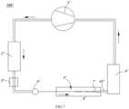
- FIG. 7 there is provided a fifth embodiment of the refrigerating system of the utility model.
- the difference between the present embodiment and the aforementioned first embodiment is only as follows:
- the egress end of the condenser 2 is provided with the drying filter 5, and the front end of the throttle pipeline 3 is fixedly connected to the drying filter 5;
- the egress end of the condenser 2' is sequentially provided with a drying filter 5' and a solenoid valve 6' from the front to the rear, and the front end of the throttle pipeline 3' is fixedly connected to the solenoid valve 6'.
- the present embodiment may also be combined with the technical content of any of the aforementioned second to fourth embodiments.
- a sixth embodiment of the present utility model further provides a refrigerating appliance, which may specifically be a refrigerator or a freezer, and may comprise the refrigerating system as described in any of the previous first to fifth embodiments, or may also comprise a refrigerating system in a variant embodiment constructed by appropriately combining technical solutions in the previous first to fifth embodiments.
- a refrigerating appliance which may specifically be a refrigerator or a freezer, and may comprise the refrigerating system as described in any of the previous first to fifth embodiments, or may also comprise a refrigerating system in a variant embodiment constructed by appropriately combining technical solutions in the previous first to fifth embodiments.
Landscapes
- Engineering & Computer Science (AREA)
- Mechanical Engineering (AREA)
- General Engineering & Computer Science (AREA)
- Physics & Mathematics (AREA)
- Thermal Sciences (AREA)
- Quick-Acting Or Multi-Walled Pipe Joints (AREA)
- Heat-Exchange Devices With Radiators And Conduit Assemblies (AREA)
Abstract
Description
- The present invention relates to a refrigerating system, and a refrigerating appliance having the same, and belongs to the technical field of household appliances.
- In a refrigerating system in currently commonly-used refrigerating appliances such as refrigerators and freezers, a capillary is usually used between a condenser and an evaporator for throttling and depressurization. In principle, a high-voltage medium-temperature liquid-phase refrigerant enters the capillary; under the action of a friction force of a wall surface of the capillary, a resistance received by the refrigerant increases gradually, the pressure and temperature of the refrigerant reduces gradually, the refrigerant finally reaches a two-phase refrigerant state under an evaporation pressure at an outlet of the capillary, and enters the evaporator at a high speed.
- However, at the connection of the capillary and the evaporator, since an inner diameter of the capillary increases abruptly, which causes a sudden change of the pressure, the refrigerant, after spurting from the capillary at a high speed, changes in phase and generates a lot of bubbles; as the pressure reduces constantly, the bubbles become larger until they break, thereby generating a spurting noise; the noise may cause the overall noise of the refrigerator to increase so that the user's experience is extremely poor.
- In order to solve the problems in the prior art, the present utility model provides a refrigerating system, and a refrigerating appliance having the same.
- To achieve the above objectives, an embodiment of the present utility model provides a refrigerating system, the refrigerating system includes a compressor, a condenser, a throttle pipeline, a transition pipe, and an evaporator connected in series in sequence, the throttle pipeline comprises a capillary body and at least two expanded pipes;
- one of the expanded pipes is connected in series between the capillary body and the transition pipe, and constitutes the last expanded pipe;
- the remaining expanded pipes are connected in series in the capillary body to divide the capillary body into at least two capillary segments, and constitute intermediate expanded pipes;
- a cross-sectional area of a channel in each of the expanded pipes is greater than the cross-sectional area of a channel in the capillary body, the cross-sectional area of the channel in the last expanded pipe or in each of the expanded pipes is smaller than the cross-sectional area of a channel in the transition pipe, and the cross-sectional area of the channel in the transition pipe is smaller than the cross-sectional area of the channel in the refrigerant pipe of the evaporator.
- As a further improvement of an embodiment of the present utility model, the expanded pipe comprises a main body pipe;
- the main body pipe is provided as a first equal-diameter pipe with a constant cross-sectional area of the channel in the pipe;
- or the main body pipe comprises a first equal-diameter pipe with a constant cross-sectional area of the channel in the pipe and at least one segment of second-equal diameter pipe connected in series behind the first equal-diameter pipe, and the cross-sectional area of the channel in each segment of second equal-diameter pipe is larger than the cross-sectional area of the channel in the first equal-diameter pipe.
- As a further improvement of an embodiment of the present utility model, the number of second equal-diameter pipes is set to two or more segments that are sequentially connected in series from front to rear, the cross-sectional area of the channels in the segments increasing gradually.
- As a further improvement of an embodiment of the present utility model, the intermediate expanded pipe is arranged such that a front end of the main body pipe of the intermediate expanded pipe is connected with a rear end of a preceding capillary segment to form a vertical stepped surface, and a rear end of the main body pipe of the intermediate expanded pipe is connected with a front end of a following capillary segment to form a vertical stepped surface;
the last expanded pipe is arranged such that the front end of main body pipe of the last expanded pipe is connected with the rear end of the last capillary segment to form a vertical stepped surface, and the rear end of the main body pipe of the last expanded pipe is connected with the front end of the transition pipe. - As a further improvement of an embodiment of the present utility model, the intermediate expanded pipe is arranged such that the rear end of the preceding capillary segment passes through the front end of the main body pipe of the intermediate expanded pipe and extends rearward into the intermediate expanded pipe, and such that the front end of the following capillary segment passes through the rear end of the main body pipe of the intermediate expanded pipe and extends forward into the intermediate expanded pipe;
the last expanded pipe is arranged such that the rear end of the last capillary segment passes through the front end of the main body pipe of the last expanded pipe and extends rearward into the last expanded pipe, the rear end of the main body pipe of the last expanded pipe being connected with the front end of the transition pipe. - As a further improvement of an embodiment of the present utility model, the expanded pipe further comprises a flared pipe connected in series between the front end of the main body pipe of the expanded pipe and the rear end of a preceding capillary segment, and a cross-sectional area of a channel in the flared pipe gradually increases from the cross-sectional area of the channel in the capillary body from front to rear to the cross-sectional area of the channel in the first equal-diameter pipe.
- As a further improvement of an embodiment of the present utility model, the intermediate expanded pipe further comprises a closure pipe connected in series between the rear end of the main body pipe and the front end of the following capillary segment, and a cross-sectional area of a channel in the closure pipe gradually decreases from the cross-sectional area of the channel in the main body pipe from the front to the rear to the cross-sectional area of the channel in the capillary body;
the rear end of the last expanded pipe is connected with the front end of the transition pipe. - As a further improvement of an embodiment of the present utility model, the cross-sectional area of the channel in the capillary body is constant, and the cross-sectional area of the channel in the main body pipe is 4 to 75 times the cross-sectional area of the channel in the capillary body.
- As a further improvement of an embodiment of the present utility model, the transition pipe comprises:
- a third equal-diameter pipe;
- a second flared pipe connected in series between the rear end of the main body pipe of the last expanded pipe and the front end of the third equal-diameter pipe, and a cross-sectional area of a channel in the second flared pipe gradually increases from the cross-sectional area of the channel in the main body pipe of the last expanded pipe at the rear end from front to rear to a cross-sectional area of a channel in the third equal-diameter pipe; and
- a third flared pipe connected in series between the rear end of the third equal-diameter pipe and the front end of the refrigerant pipe of the evaporator, and a cross-sectional area of a channel in the third flared pipe gradually increases from the cross-sectional area of the channel in the third equal-diameter pipe from front to rear to the cross-sectional area of the channel in the refrigerant pipe of the evaporator.
- As a further improvement of an embodiment of the present utility model, the transition pipe is provided as a flared transition pipe, and a cross-sectional area of the channel in the flared transition pipe gradually increases from the cross-sectional area of the channel in the main body pipe of the last expanded pipe at the rear end from front to rear to the cross-sectional area of the channel in the refrigerant pipe of the evaporator.
- As a further improvement of an embodiment of the present utility model, the throttle pipeline, on the whole, is provided as a rigid pipe integrally formed of copper or steel,
- or the throttle pipeline is, on the whole, provided as a flexible pipe;
- or the throttle pipeline is arranged such that one section of the pipeline is a flexible pipe, and the remaining section of the pipeline is a rigid pipe integrally formed of copper or steel.
- As a further improvement of an embodiment of the present utility model, a section of the throttle pipeline extending from rear to front from the rear end of the last expanded pipe, at least to the front end of the last intermediate expanded pipe is set as a flexible pipe.
- As a further improvement of an embodiment of the present utility model, all the transition pipe or a portion from the front end of the transition pipe is set as the flexible pipe, and integrally formed with the flexible pipe of the throttle pipeline.
- As a further improvement of an embodiment of the present utility model, the throttle pipeline is disposed in a sole refrigerant flow path that communicates an egress end of the condenser with an ingress end of the evaporator.
- As a further improvement of an embodiment of the present utility model, the egress end of the condenser is provided with a drying filter, and a front end of the throttle pipeline is fixedly fitted with the drying filter;
or the egress end of the condenser is sequentially provided with a drying filter and a solenoid valve from the front to the rear, and the front end of the throttle pipeline is fixedly connected to the solenoid valve. - To achieve the above objectives, an embodiment of the present utility model provides a refrigerating appliance includes the refrigerating system.
- As compared with the prior art, advantageous effects of the present utility model are as follows: the refrigerating system achieves stage-wise attenuation and smoothing of the spurt and pulsation, substantially reduces the problem of the noise caused by the break of bubbles during the spurting, decreases the outward, forward and backward transfer of the spurting pulsation along the pipeline of the refrigerating system, and avoids the noise amplification phenomenon caused by vibration transmission, by disposing the expanded pipes in the middle of and at the rear end of the capillary body, disposing the transition pipe between the last expanded pipe and the refrigerant pipe of the evaporator, and setting the relationship of the magnitude of the cross-sectional areas of the channels in the capillary body, expanded pipes, transition pipe, and the refrigerant pipe of the evaporator.
-
-
FIG. 1 is a schematic view of a refrigerating system of a first embodiment of the present utility model; -
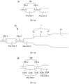
FIG. 2a is a structural view of a throttle pipe in the first embodiment of the present utility model; -
FIG. 2b is a structural schematic view of the throttle pipe, a transition pipe, and part (corresponding to Area A inFIG. 1 ) of a refrigerant pipe of an evaporator in the first embodiment of the present utility model; -
FIG. 3a is an exploded sectional view of a pipe connection mechanism of the first embodiment of the present utility model; -
FIG. 3b is a structural sectional view illustrating the fitting of the pipe connection mechanism and a flexible pipe in the first embodiment of the present utility model; -
FIG. 4a is a structural view of a throttle pipe in a second embodiment of the present utility mode; -
FIG. 4b is a structural schematic view of the throttle pipe, a transition pipe, and part (corresponding to Area A inFIG. 1 ) of a refrigerant pipe of an evaporator in the second embodiment of the present utility model; -
FIG. 5a is a structural view of a throttle pipe in a third embodiment of the present utility model; -
FIG. 5b is a structural schematic view of the throttle pipe, a transition pipe, and part (corresponding to Area A inFIG. 1 ) of a refrigerant pipe of an evaporator in a third embodiment of the present utility model; -
FIG. 6a is a structural view of a throttle pipe in a fourth embodiment of the present utility model; -
FIG. 6b is a structural schematic view of the throttle pipe, a transition pipe, and part (corresponding to Area A inFIG. 1 ) of a refrigerant pipe of an evaporator in a fourth embodiment of the present utility model; -
FIG. 7 is a schematic view of a refrigerating system in a fifth embodiment of the present utility model. - The present utility model will be described in detail in conjunction with specific embodiments shown in the figures. However, these embodiments are not intended to limit the present utility model. Structural, methodological or functional variations made by those having ordinary skill in the art according to these embodiments are all included in the protection scope of the present utility model.
- Referring to
FIG. 1 through FIG. 3b , they illustrate arefrigerating system 100 in a first embodiment of the present utility model. - Referring to
FIG. 1 , the refrigeratingsystem 100 has a flow circuit in which a refrigerant flows in a circulating manner. In a front-rear direction defined by a flow direction of the refrigerant, the refrigeratingsystem 100 comprises acompressor 1, acondenser 2, athrottle pipeline 3, atransition pipe 7, and anevaporator 4 connected in series in sequence. - Specifically, an exhaust pipe of the
compressor 1 is connected to an ingress end of thecondenser 2, and a gas return pipe of thecompressor 1 is connected to an egress end of theevaporator 4; thethrottle pipeline 3 is communicated between an egress end of thecondenser 2 and an ingress end of theevaporator 4. - A circulation process of the refrigerant in the
refrigerating system 100 is theoretically roughly as follows: a high-temperature and high-pressure superheated refrigerant gas in the exhaust pipe of thecompressor 1 enters thecondenser 2 and is condensed into a high-pressure saturated or supercooled liquid which then enters thethrottle pipeline 3 for throttling and depressurization, and then flows through thetransition pipe 7 into theevaporator 4 for vaporization into a low-temperature and low-pressure refrigerant gas, which returns to thecompressor 1 to be recompressed into a high-temperature and high-pressure superheated refrigerant gas, thereby completing the entire circulation process. - In the present utility model, the pipeline structure formed by the
throttle pipeline 3, thetransition pipe 7 and the ingress end of therefrigerant pipe 41 of theevaporator 4 is improved to solve the problem about the spurting of noise in the prior art. - Specifically, the
throttle pipeline 3 comprises acapillary body 30 and an expanded pipe 31. Thecapillary body 30 is a capillary pipe in which a channel has a constant cross-sectional area and which is constructed to have a length of more than half of thethrottle pipeline 3; a cross-sectional area of a channel in the expanded pipe 31 is greater than the cross-sectional area of the channel in thecapillary body 30. - Referring to
FIG. 2a andFIG. 2b , thethrottle pipeline 3 comprises at least two expanded pipes 31 spaced sequentially from front to rear. One of the expanded pipes 31 is connected in series between thecapillary body 30 and thetransition pipe 7, that is, the expanded pipe 31 defines a rear end of thethrottle pipeline 3; the remaining expanded pipes 31 are connected in series in thecapillary body 30 to divide thecapillary body 30 into at least two capillary segments. - In the present application, the expanded pipes are distinguished in a way that one expanded pipe 31 connected in series between the
capillary body 30 and thetransition pipe 7 is defined as the last expanded pipe 31-2, and the remaining expanded pipes 31 connected in series in thecapillary body 30 are defined as intermediate expanded pipes 31-1, for ease of understanding and description. - As stated above, if the number of expanded pipes 31 is at least two, the number of intermediate expanded pipes 31-1 is at least one. Accordingly, the at least one intermediate expanded pipe 31-1 divides the
capillary body 30 into at least two capillary segments. To put it another way, thecapillary body 30 comprises at least two spaced-apart capillary segments, and two adjacent capillary segments are communicated through an intermediate expanded pipe 31-1. In this way, thethrottle pipeline 3 constitutes a pipeline structure of [capillary-- middle expanded pipe 31-1] ∗n-capillary-- last expanded pipe 31-2, where n is a positive integer. - In the present embodiment, the number of expanded pipes 31 is exemplified as two: one last expanded pipe 31-2, and one intermediate expanded pipe 31-1; wherein the one intermediate expanded pipe 31-1 divides the
capillary body 30 into two capillary segments, namely, the capillary 30-1 and the capillary 30-2; the last expanded pipe 31-2 is connected between the last capillary segment (i.e., capillary 30-2) and thetransition pipe 7. Certainly, it may be appreciated that the number of expanded pipes 31 may be three or more, and accordingly, thecapillary body 30 is divided into three or more capillary segments. - The cross-sectional area of the channel in the last expanded pipe 31-2 is smaller than the cross-sectional area of the channel in the
transition pipe 7; furthermore, the cross-sectional area of the channel in thetransition pipe 7 is smaller than the cross-sectional area of the channel in therefrigerant pipe 41 of theevaporator 4. - Therefore, as compared with prior art, the refrigerating
system 100 according to the present embodiment achieves stage-wise attenuation and smoothing of the spurt and pulsation, substantially reduces the problem of the noise caused by the break of bubbles during the spurting, decreases the outward, forward and backward transfer of the spurting pulsation along the pipeline of therefrigerating system 100, and avoids the noise amplification phenomenon caused by vibration transmission, by disposing the expanded pipes 31 in the middle of and at the rear end of thecapillary body 30, disposing thetransition pipe 7 between the last expanded pipe 31-2 and therefrigerant pipe 41 of theevaporator 4, and setting the relationship of the magnitude of the cross-sectional areas of the channels in thecapillary body 30, expanded pipes 31,transition pipe 7, and therefrigerant pipe 41 of theevaporator 4. - In the present embodiment, the cross-sectional area of the channel in each expanded pipe 31 among all the expanded pipes 31 including the last expanded pipe 31-2 is smaller than the cross-sectional area of the channel in the
transition pipe 7. As such, the cross-sectional area of the channel in thethrottle pipeline 3 is smaller than the cross-sectional area of the channel in thetransition pipe 7. - On the one hand, since there is the capillary 30-2 behind the intermediate expanded pipe 31-1, under a pressure-retaining effect of the capillary 30-2, the refrigerant will not spurt at a high rate like a conventional capillary spurting port when the refrigerant enters the middle expanded pipe 31-1, and the refrigerant will not generate a lot of bubbles like the conventional capillary spurting port when the refrigerant flows in the middle expanded pipe 31-1, and the bubbles will break with a small volume and will not generate a large noise; on the other hand, the refrigerant mostly spurts upon entering the last expanded pipe 31-2 and the transition pipe 7 from the capillary; since the refrigerant is already partly converted from a liquid phase into a gaseous phase at the preceding middle expanded pipe 31-1, the gas phase in the refrigerant entering the last expanded pipe 31-2 is in a larger proportion as compared with the conventional capillary spurting port; then, the cross-sectional area in the channels in the last expanded pipe 31-2, the transition pipe 7 and the refrigerant pipe 41 of the evaporator 4 gradually increases, the pulsation of the liquid flow is attenuated and smoothed so that the spurting noise is very small; in another aspect, since after the pulsation of the liquid flow is gradually attenuated and smoothed after the liquid flows through at least two expanded pipes 31, the vibration greatly reduces; furthermore, the forward vibration along the pipeline of the refrigerant is absorbed at the intermediate expanded pipe 31-1, and the rearward vibration is absorbed at the last expanded pipe 31-2, substantially reducing the noise amplification phenomenon caused by the outward transmission of the pulsation upon the spurting.
- Furthermore, referring to
FIG. 1 , the egress end of thecondenser 2 and the ingress end of theevaporator 4 are communicated through a sole refrigerant flow path, and thethrottle pipeline 3 is disposed in the sole refrigerant flow path that communicates the egress end of thecondenser 2 with the ingress end of theevaporator 4. That is, when therefrigerating system 100 performs refrigeration, the refrigerant in thecondenser 2 inevitably needs to enter theevaporator 4 through thethrottle pipeline 3. - In the present embodiment, the egress end of the
condenser 2 is provided with a dryingfilter 5, and a front end of thethrottle pipeline 3 is fixedly fitted with the dryingfilter 5, that is, the front end of the foremost capillary segment 30-1 is fixedly fitted with the dryingfilter 5. - Furthermore, any two expanded pipes 31 may be set in the same shape or different shapes.
- In the present embodiment, any two expanded pipes 31 may be set in the same shape. Each expanded pipe 31 comprises a main body pipe provided as a first equal-diameter pipe with a constant cross-sectional area of the channel in the pipe. More specifically, each expanded pipe 31 is provided as an equal-diameter pipe structure.
- Specifically, the intermediate expanded pipe 31-1 is arranged such that a front end of the main body pipe of the intermediate expanded pipe 31-1 is connected with a rear end of a preceding capillary segment 30-1 to form a vertical stepped surface, and a rear end of the main body pipe of the intermediate expanded pipe 31-1 is connected with a front end of a following capillary segment 30-2 to form a vertical stepped surface.
- The last expanded pipe 31-2 is arranged such that the front end of main body pipe of the last expanded pipe 31-2 is connected with the rear end of the capillary 30-2 to form a vertical stepped surface, and the rear end of the main body pipe of the last expanded pipe 31-2 is connected with the front end of the
transition pipe 7. - Furthermore, the cross-sectional area of the channel in the main body pipe of each expanded pipe 31 is 4 to 75 times the cross-sectional area of the channel in the
capillary body 30. - Furthermore, in the present embodiment, the
transition pipe 7 comprises an equal-diameter pipe 72, a flaredpipe 71, and a flaredpipe 73. - The flared
pipe 71 and the flaredpipe 73 are connected to a front end and a rear end of the equal-diameter pipe 72, respectively. - The flared
pipe 71 is connected in series between the rear end of thethrottle pipeline 3 and the front end of the equal-diameter pipe 72, and is specifically connected in series between the rear end of the main body pipe of the last expanded pipe 31-2 and the front end of the equal-diameter pipe 72. The cross-sectional area of a channel in the flaredpipe 71 gradually increases from the cross-sectional area of the channel in the main body pipe of the last expanded pipe 31-2 at the rear end from front to rear to the cross-sectional area of the channel in the equal-diameter pipe 72, i.e., the cross-sectional area of the channel in the flaredpipe 71 at the front end is equal to the cross-sectional area of the channel in the main body pipe of the last extended pipe 31-2 at the rear end, and the cross-sectional area of the channel in the flaredpipe 72 at the rear end is equal to the cross-sectional area of the channel in the equal-diameter pipe 72. - The flared
pipe 73 is connected in series between the rear end of the equal-diameter pipe 72 and the front end of therefrigerant pipe 41 of theevaporator 4. The cross-sectional area of a channel in the flaredpipe 73 gradually increases from the cross-sectional area of the channel in the equal-diameter pipe 72 from front to rear to the cross-sectional area of the channel in therefrigerant pipe 41 of theevaporator 4. - In this way, with the flared
pipe 71 and the flaredpipe 73 being provided, it is possible to achieve a smooth transition between the cross-sectional area of the channel in the equal-diameter pipe 72 of thetransition pipe 7 and the cross-sectional area of the channel in thethrottle pipeline 3 and the cross-sectional area of the channel in theevaporator 4, and to avoid the problem of the noise caused by sudden changes in the cross-sectional area of the channels in these pipes. Certainly, in a variant embodiment, thetransition pipe 7 may also be provided as a flared transition pipe, and the cross-sectional area of the channel ins the flared transition pipe gradually increases from the cross-sectional area of the channel in the main body pipe of the last expanded pipe 31-2 at the rear end from front to rear to the cross-sectional area of the channel in therefrigerant pipe 41 of theevaporator 4, i.e., thethrottle pipeline 3 is connected to therefrigerant pipe 41 of theevaporator 4 via the flared transition pipe. - Preferably, in the present embodiment, both the
throttle pipeline 3 and thetransition pipe 7 are provided as circular pipes, and the cross sections of the channels in thethrottle pipeline 3 and thetransition pipe 7 at all positions are circular. Certainly, the shapes of the cross sections of the channels in thethrottle pipeline 3 andtransition pipe 7 at all positions are not limited to this, and may also be square, hexagonal, elliptical, waist-shaped, or other feasible suitable shapes. - Correspondingly, the size relationship of the cross-sectional area of the channels in the respective pipes described above corresponds to the size relationship of inner diameters of the respective pipes. For example, if the cross-sectional area of the channel in the
throttle pipeline 3 is smaller than the cross-sectional area of the channel in thetransition pipe 7, the inner diameter of thethrottle pipeline 3 is correspondingly smaller than the inner diameter of thetransition pipe 7. - In addition, in the present embodiment an inner wall of the flared
pipe 71 may be set as an inclined surface or an inwardly-convex arc surface or an outwardly-recessed arc surface in a front-rear direction, and likewise, an inner wall of the flaredpipe 73 may also be set as an inclined surface or an inwardly-convex arc surface or an outwardly-recessed arc surface in a front-rear direction. Certainly, an inner wall of the flared transition pipe in a variant embodiment may be also set as an inclined surface in a front-rear direction or an inwardly-convex arc surface or an outwardly-recessed arc surface. - Preferably, the
throttle pipeline 3 is arranged such that one section of the pipeline is a flexible pipe, and the remaining section of the pipeline is a rigid pipe integrally formed of copper or steel. Specifically, a rear section of thethrottle pipeline 3 is a flexible pipe and a front section of thethrottle pipeline 3 is a rigid pipe integrally formed of copper or steel. - In the present embodiment, a section extending from rear to front from the rear end (as indicated by C8 in
FIG. 2b ) of the last expanded pipe 31-2, at least to the front end (as indicated by C2 inFIG. 2b ) of the last intermediate expanded pipe 31-1 is set as the flexible pipe, i.e., a section of thethrottle pipeline 3 between the position indicated by C2 and the position indicated by C8 inFIG. 2b is the flexible pipe, and the section of thethrottle pipeline 3 before the position indicated by C2 is the rigid pipe. In this way, on the one hand, the vibration of the break of the bubbles generated in the spurting of the last expanded pipe 31 acts on the wall of the flexible pipe and may be absorbed by the flexible pipe, thereby ensuring effective reduction of the vibration and noise; on the other hand, the flexible pipe may also avoid the forward and backward transmission of the vibration along thethrottle pipeline 3, thereby reducing the transmission of the vibration. - More preferably, a section of the
throttle pipeline 3 extending from rear to front from the rear end (as indicated by C8 inFIG. 2b ) of the last expanded pipe 31-2, to the front end of the frontmost intermediate expanded pipe 31-1 is set as the flexible pipe, i.e., all the expanded pipes 31 and the capillaries between the expanded pipes 31 are all set as the flexible pipes, and only the frontmost capillary segment 30-1 is set as the rigid pipe; it may be appreciated that corresponding to the present embodiment shown in the figures, as previously described there is only one intermediate expanded pipe 31-1 so that the frontmost intermediate expanded pipe 31-1 is the last intermediate expanded pipe 31-1, and is all the intermediate expanded pipe 31-1, and the front end of the frontmost intermediate expanded pipe 31-1 is the position indicated by C2 in the figure. In this way, the vibration of the break of the bubbles occurring in each expanded pipe 31 directly acts on the wall of the flexible pipe, and may be absorbed by the flexible pipe, thereby reducing the outward transmission of the vibration. - Furthermore, in the present embodiment, the rigid pipe of the
throttle pipeline 3 may be fixedly connected with the dryingfilter 5 by welding or other means, that is, the front end of thecapillary body 30 may be fixedly connected with the dryingfilter 5 by welding or other means. - Furthermore, the flexible pipe of the
throttle pipeline 3 is integrally formed with all or part of thetransition pipe 7, that is, all or part of thetransition pipe 7 is also provided as a flexible pipe, and the flexible pipe of thetransition pipe 7 and the flexible pipe of thethrottle pipeline 3 are integrally arranged. For example, thetransition pipe 7 may be provided in a way that the flaredpipe 71 is a flexible pipe and the remaining pipe section of thetransition pipe 7 is a rigid pipe, or in a way that the flaredpipe 71 and the equal-diameter pipe 72 are flexible pipes and the remaining pipe section is a rigid pipe, or in a way that all of thetransition pipe 7 is a flexible pipe. In this way, the vibration caused by the break of the bubbles at thetransition pipe 7 may act on the pipe wall of the flexible pipe, and the vibration may be absorbed by the flexible pipe, thereby ensuring effective reduction of the vibration and noise. - According to the foregoing, in the present embodiment, an integrally formed flexible pipe body is disposed in the pipeline composed of the
throttle pipeline 3, thetransition pipe 7, and therefrigerant pipe 41 of the evaporator 4: the front end of the flexible pipe body is located at the position indicated by C2 shown inFIG. 2b , and is connected with the preceding rigid pipe body at the position indicated by C2; the rear end of the flexible pipe body is located in the middle (e.g., at a position indicated by C9 or C10 or C11) or at the rear end (e.g., at a position indicated by C12) of thetransition pipe 7, and is connected with the following rigid pipe body at the corresponding position. - Certainly, it may be appreciated that in a variant embodiment, the front end of the flexible pipe body may also be located at other positions besides C2, for example, in the middle (the position indicated by C3 of
FIG. 2b ) or at the rear end (the position indicated by C4 ofFIG. 2b ) of any intermediate expanded pipe 31-1, or at the front end (the position indicated by C6 ofFIG. 2b ) of the last expanded pipe 31-2; in another variant embodiment, the rear end of the flexible pipe body may also be located at other positions besides C9 or C10 or C11 or C12, for example located at the rear end (the position indicated by C8 ofFIG. 2b ) of the last expanded pipe 31-2. In this case, thetransition pipe 7, on the whole, is provided as a rigid pipe integrally formed of copper or steel, and is assembled and connected with thethrottle pipeline 3; In yet another variant embodiment, the rear end of the flexible pipe body may also be located in the middle (the position indicated by C7 ofFIG. 2b ) of or at a more forward position of the last expanded pipe 31-2. In this case, the rear pipe segment of the last expanded pipe 31-2 is a rigid pipe integrally formed of copper or steel, may be fixedly connected to thetransition pipe 7 by welding or other means, or may be integrally formed with thetransition pipe 7; In a further variant embodiment, thethrottle pipeline 3 may be provided as a flexible pipe on the whole, assembled and connected with the dryingfilter 5, fixedly assembled and connected with thetransition pipe 7, or may be integrally formed with all or part of thetransition pipe 7; In a further variant embodiment, thethrottle pipeline 3 may be provided as a rigid pipe integrally formed of copper, steel, or other materials, fixedly connected with the dryingfilter 5 by welding or other means, fixedly connected with thetransition pipe 7 by welding or other means, or integrally formed with all or part of thetransition pipe 7. - Furthermore, in the present embodiment, with reference to
FIG. 3a and FIG. 3b , the aforementioned flexible pipe body and rigid pipe body may be assembled and connected through apipe connecting mechanism 9. That is, thepipe connecting mechanism 9 may achieve a fixed connection between theflexible pipe body 90 and the rigid pipe body, thereby enabling the refrigerant to flow smoothly from theflexible pipe body 90 into the rigid pipe body, or from the rigid pipe body into theflexible pipe body 90. - To facilitate understanding and depiction, the
pipe connecting mechanism 9 at the rear end of theflexible pipe body 90 is taken as an example to introduce the structure of thepipe connecting mechanism 9 in detail, i.e., hereunder, the orientations of the front and rear of parts of thepipe connecting mechanism 9 are based on a reference premise that theflexible pipe body 90 is in the front and the rigid pipe body is in the rear; correspondingly, if thepipe connecting mechanism 9 is at the front end of theflexible pipe body 90, i.e., the reference premise is that theflexible pipe body 90 in the rear and the rigid pipe body in the front, orientations of the front and rear of parts of thepipe connecting mechanism 9 all will change to the reverse. For example, hereinafter, "afirst pipe portion 922 is formed at a rear end of aconnector pipe 92, and asecond pipe portion 921 is formed at a front end of theconnector pipe 92" should be changed to "afirst pipe portion 922 is formed at a front end of aconnector pipe 92, and asecond pipe portion 921 is formed at a rear end of theconnector pipe 92". - Specifically, the
pipe connecting mechanism 9 at the rear end of theflexible pipe body 90 is taken as an example. Thepipe connecting mechanism 9 comprises aconnector pipe 92 and asleeve 91. - The
connector pipe 92 is provided as a straight pipe extending in a front-rear direction, and has afirst pipe portion 922 and asecond pipe portion 921 arranged at opposite ends, respectively. Thefirst pipe portion 922 is formed at a rear end of theconnector pipe 92, and thesecond pipe portion 921 is formed at a front end of theconnector pipe 92. - The
first pipe portion 922 is fixedly connected to the rigid pipe body, thesecond pipe portion 921 is inserted into theflexible pipe body 90 from the rear to the front, and thesecond pipe portion 921 supports theflexible pipe body 90 in an interference-fitted manner. - The
sleeve 91 is sleeved outside theflexible pipe body 90 and moves towards theconnector pipe 92 from front to back, and is sleeved outside thesecond pipe portion 921. In this way, thesleeve 91 may clamp and fix theflexible pipe body 90 together with thesecond pipe portion 921, that is, thesecond pipe portion 921 supports theflexible pipe body 90 from the inside in an interference-fitted manner, while thesleeve 91 presses theflexible pipe body 90 from the outside inward, so that theflexible pipe body 90 is tightly clamped and fixed between thesleeve 91 and thesecond pipe portion 921. - In this way, the
pipe connecting mechanism 9 ensures the sealing performance between theflexible pipe body 90 and thesecond pipe portion 921, and avoids the refrigerant from leaking along a gap between theflexible pipe body 90 and thesecond pipe portion 921 in a way that thesecond pipe portion 921 supports theflexible pipe body 90 in an interference-fitted manner. Meanwhile, thepipe connecting mechanism 9 may quickly achieve the connection between theflexible pipe body 90 and the rigid pipe body through the plugging operation between both of thesleeve 91 andconnector pipe 92 and theflexible pipe body 90, without requiring other extra structural members (i.e., thepipe connecting mechanism 90 only needs to consist of thesleeve 91 and the connector pipe 92). The pipe connecting mechanism is simple in structure, simple and convenient in operation, highly efficient in assembling and integrates two aspects, namely, the assembling efficiency and the sealing performance. - Furthermore, the
first pipe portion 922 may be specifically connected to the rigid pipe body by welding. Certainly, in a variant embodiment, theconnector pipe 92 may also be integrally formed with the rigid pipe body, i.e., may be directly formed by machining at an end of the rigid pipe body. - Preferably, a cross section of an
outer surface 9210 of thesecond pipe portion 921 is set to a circular shape, and correspondingly, an inner cavity of thesleeve 91 is set to a circular shape, i.e., the cross section of an inner surface of thesleeve 91 is set to a circular shape, which may facilitate fitting and avoid damaging theflexible pipe body 90 by cutting at sharp angles. - Furthermore, an inner radius R1 of the
sleeve 91 is larger than an outer radius R2 of thesecond pipe portion 921, and a difference (R1-R2) between the inner radius R1 of thesleeve 91 and the outer radius R2 of thesecond pipe portion 921 is smaller than a thickness H of the pipe wall of theflexible pipe body 90, thereby ensuring that theflexible pipe body 90 is further sandwiched through thesleeve 91 and thesecond pipe portion 921. - In addition, in the present embodiment, the
outer surface 9210 of thesecond pipe portion 921 is provided with an antiskid structure. When thesecond pipe portion 921 supports theflexible pipe body 90 with in an interference-fitted manner, the antiskid structure increases the firmness of theflexible pipe body 90 on thesecond pipe portion 921, and may prevent theflexible pipe body 90 from detaching from thesecond pipe portion 921, and meanwhile may also increase the difficulty of the refrigerant in leaking from between theflexible pipe body 90 and thesecond pipe portion 921, thereby ensuring the sealing effect. - The antiskid structure is configured as a protrusion protruding outwardly from the
outer surface 9210 of thesecond pipe portion 921, or as a groove recessed inwardly into theouter surface 9210 of thesecond pipe portion 921. - Furthermore, the
connector pipe 92 has a limitingboss 920 protruding outward from thesecond pipe portion 921, that is, an outer surface of the limitingboss 920 is arranged away from an axis T relative to theouter surface 9210 of thesecond pipe portion 921. Afront end face 9201 of the limitingboss 920 may resist a rear end face of thesleeve 91, thereby defining an extremity position of thesleeve 91 upon moving rearward. - In this way, when the
flexible pipe body 90 and the rigid pipe body are assembled, the assembling may be completed when the rear end face of thesleeve 91 abuts against thefront end face 9201 of the limitingboss 920, which may facilitate the operator to judge that the flexible pipe body and the rigid pipe body are mounted in position, avoid blind over-assembling, and meanwhile facilitate precisely controlling the length of a refrigerant flow path at theflexible pipe body 90 in the refrigerating system. - Preferably, the limiting
boss 920 extends about the axis T of thesecond pipe portion 921 and assumes a shape of an annular boss, i.e., the limitingboss 920 extends around the circumference of thesecond pipe portion 921 about the axis T. As such, when the assembling of theflexible pipe body 90 and the rigid pipe body is completed through thepipe connecting mechanism 9, thefront end face 9201 of the limitingboss 920 may abut against the rear end face of thesleeve 91 in the circumferential direction, thereby further extending a path on which the refrigerant leaks out of thepipe connecting mechanism 9 and enhancing the sealing effect. - Furthermore, an outer diameter of a front
end pipe portion 911 of thesleeve 91 is smaller than the outer diameter of a rearend pipe portion 912 of thesleeve 91, so that the outer surface of thesleeve 91 is stepped, that is, the frontend pipe portion 911 is relatively thin and the rearend pipe portion 912 is relatively thick. An outer surface of the frontend pipe portion 911 and an outer surface of the rearend pipe portion 912 are connected through asurface 9121. In other words, thesurface 9121 may be taken as the front end face of the rearend pipe portion 912. In this way, with the structure that is thin in the front and thick in the rear being provided, when thesleeve 91 is sleeved to the outside of thesecond pipe portion 921, thesurface 9121 is pushed forward to apply a pushing force to press thesleeve 91 towards the limitingboss 920, which facilitates the application of the force during mounting. - Similarly, the limiting
boss 920 also protrudes outward from thefirst pipe portion 922, that is, the outer surface of the limitingboss 920 is arranged away from the axis T relative to the outer surface of thefirst pipe portion 922. The outer surface of the limitingboss 920 and the outer surface of thefirst pipe part 922 are connected in a stepped shape through thesurface 9202. In other words, thesurface 9202 may be regarded as the rear end face of the limitingboss 920. In this way, when thesleeve 91 is sleeved to the outside of thesecond pipe portion 921, thesurface 9202 is pushed rearward to apply a pushing force to press thesleeve 91 towards the limitingboss 920, which facilitates the application of the force during mounting. - Furthermore, the
sleeve 91 is provided as an integrally-formed metal member, and theconnector pipe 92 is also provided as an integrally-formed metal member. Both thesleeve 91 and theconnector pipe 92 may be made of copper, steel, or other materials. - The above only provides one type of
pipe connecting mechanism 9 for application in therefrigerating system 100 to thereby assemble and connect the rigid pipe body with the flexible pipe body of thethrottle pipeline 3 and/or the flexible pipe body of thetransition pipe 7. Certainly, it may be appreciated that other pipe connecting structures known in the art may also be used to achieve the connection of the rigid pipe body with the flexible pipe body of thethrottle pipeline 3 and/or the flexible pipe body of thetransition pipe 7, and the present utility model is not limited to thispipe connecting mechanism 9. - Hereunder, referring to
FIG. 4a and FIG. 4b , a second embodiment of the refrigerating system of the present utility model is provided. The difference between the present embodiment and the aforementioned first embodiment is only as follows: - In the present embodiment, the front end of the main body pipe of the intermediate expanded
pipe 31a-1 and the rear end of the preceding capillary 30a-1 are not connected in a vertical stepped surface as in the first embodiment, but are arranged such that the rear end of the preceding capillary 30a-1 passes through the front end of the main body pipe of the intermediate expandedpipe 31a-1 and extends rearward into the intermediate expandedpipe 31a-1; moreover, the rear end of the main body pipe and the front end of the followingcapillary segment 30a-2 are not connected in a vertical stepped surface as in the first embodiment, but are arranged such that the front end of the followingcapillary segment 30a-2 passes through the rear end of the main body pipe of the intermediate expandedpipe 31a-1 and extends forward into the intermediate expandedpipe 31a-1. - Similarly, the front end of the main body pipe of the last expanded
pipe 31a-2 and the rear end of the capillary 30a-2 are not connected in a vertical stepped surface as in the first embodiment, but are arranged such that the rear end of the capillary 30a-2 passes through the front end of the main body pipe of the last expandedpipe 31a-2 and extends rearward into the last expandedpipe 31a-2. - That is, in the present embodiment, an insertion type structure is employed between the capillary 30a and each expanded
pipe 31a. The end of the capillary 30a is inserted into the expandedpipe 31a, and the end of thecapillary body 30a is wrapped from the outside by the refrigerant in the expandedpipe 31a. - The remaining technical content of the present embodiment is the same as that of the first embodiment, and will not be further described.
- Next, with reference to
FIG. 5a andFIG. 5b , a third embodiment of the refrigerating system of the present utility model is provided. The difference between the present embodiment and the aforementioned first embodiment is as follows: - In the aforementioned first embodiment, each expanded pipe 31 is provided with an equal-diameter pipe structure, which comprises a main body pipe. The main body pipe is provided with a first equal-diameter pipe with a constant cross-sectional area of the channel inside the pipe, and the first equal-diameter pipe is also the main body pipe, namely, the expanded pipe 31;
- However, in the present embodiment, the expanded
pipe 31b is not configured as an equal-diameter pipe structure. The expandedpipe 31b comprises amain body pipe 312b configured as the first equal-diameter pipe, and the cross-sectional area of the channel in themain body pipe 312b is 4 to 75 times the cross-sectional area of the channel in the capillary body 10, and each expandedpipe 31b further comprises a flaredpipe 311b. - The flared
pipe 311b is connected in series between the front end of themain body pipe 312b and the rear end of the preceding capillary 30b-1, that is, a front end of the flaredpipe 311b starts from the rear end of the preceding capillary 30b-1, and a rear end of the flaredpipe 311b terminates at the front end of themain body pipe 312b; Moreover, the cross-sectional area of the channel in the flaredpipe 311b gradually increases from the cross-sectional area of the channel in thecapillary body 30b from the front to the rear to the cross-sectional area of the channel in the first equal-diameter pipe (i.e., themain body pipe 312b). - If the
throttle pipeline 3 is arranged as a circular pipe, an inner diameter of the flaredpipe 311b assumes an inclined surface or an inwardly-convex arc surface or an outwardly-recessed arc surface in a front-rear direction, and the inner diameter of the flaredpipe 311b gradually increases from the inner diameter of thecapillary body 30b to the inner diameter of the first equal-diameter pipe (i.e., themain body pipe 312b). In this way, the refrigerant may smoothly enter themain body pipe 312b of the expandedpipe 31b from the capillary, reducing the flow noise caused by sudden changes in the inner diameter of the pipe. - Furthermore, the difference between the present embodiment and the aforementioned first embodiment is that the intermediate expanded
pipe 31b-1 further comprisesclosure pipes 313b. - The
closure pipes 313b are connected in series between the rear end of themain body pipe 312b and the front end of the followingcapillary segment 30b-2, that is, a front end of theclosure pipe 313b starts from the rear end of themain body pipe 312b, and a rear end of theclosure pipe 313b terminates at the front end of the followingcapillary segment 30b-2; in addition, a cross-sectional area of a channel in theclosure pipe 313b gradually decreases from the cross-sectional area of the channel in themain body pipe 312b from the front to the rear to the cross-sectional area of the channel in thecapillary body 30b. - In a case where the
throttle pipeline 3 is arranged as a circular pipe, an inner diameter of theclosure pipe 313b assumes an inclined surface or an inwardly-convex arc surface or an outwardly-recessed arc surface in a front-rear direction, and the inner diameter of the first equal-diameter pipe (namely, themain body pipe 312b) gradually reduces to the inner diameter of thecapillary body 30b. In this way, the refrigerant may smoothly enter the capillary from themain body pipe 312b of the expandedpipe 31b, reducing the flow noise caused by sudden changes in the inner diameter of the pipe. - The remaining technical content of the present embodiment is the same as that of the first embodiment, and will not be further described.
- Hereinafter, with reference to
FIG. 6a and FIG. 6b , a fourth embodiment of the refrigerating system of the present utility model is provided. - The difference between the present embodiment and the aforementioned first embodiment is as follows:
- In the aforementioned first embodiment, each expanded pipe 31 is provided with an equal-diameter pipe structure, which comprises a main body pipe. The main body pipe is provided with a first equal-diameter pipe with a constant cross-sectional area of the channel inside the pipe, and the first equal-diameter pipe is also the main body pipe, namely, the expanded pipe 31;
- However, in the present embodiment, the main body pipe of expanded
pipe 31c is not configured as an equal-diameter pipe structure. Specifically, the expandedpipe 31c comprises a first equal-diameter pipe 311c, and a cross-sectional area of the channel in the first equal-diameter pipe 311c is 4 to 75 times the cross-sectional area of the channel in the capillary body 10. The main body pipe of the expandedpipe 31b further comprises one or two or more segments of a second-equal diameter pipe 312c connected in series behind the first equal-diameter pipe 311c. The cross-sectional area of the channel in each segment of the second equal-diameter pipe 312c is larger than the cross-sectional area of the channel in the first equal-diameter pipe 311c. - In the figures, the number of second equal-
diameter pipes 312c is set to one segment, whereby the main body pipe of the expandedpipe 31c is formed by sequentially connecting thinner first equal-diameter pipes 311c with thicker second equal-diameter pipes 312c from front to rear. Certainly, in a variant embodiment, the number of second equal-diameter pipes 312c is set to two or more segments. At this time, the cross-sectional areas of the channels in respective segments of second equal-diameter pipe 312c are different, and the cross-sectional areas of the channels in the respective segments of second equal-diameter pipe 312 that are sequentially connected from front to rear increases segment by segment. - The remaining technical content of the present embodiment is the same as that of the first embodiment, and will not be repeated any longer. Certainly, in a variant embodiment, the structure between the expanded
pipe 31c and thecapillary body 30c of the present embodiment may also be set as the insertion type structure of the second embodiment, or may also be combined with the technical content of the third embodiment to obtain a corresponding structural change. - Hereinafter, referring to
FIG. 7 , there is provided a fifth embodiment of the refrigerating system of the utility model. The difference between the present embodiment and the aforementioned first embodiment is only as follows: - In the first embodiment, the egress end of the
condenser 2 is provided with the dryingfilter 5, and the front end of thethrottle pipeline 3 is fixedly connected to the dryingfilter 5; - However, in the present embodiment, the egress end of the
condenser 2' is sequentially provided with a drying filter 5' and a solenoid valve 6' from the front to the rear, and the front end of the throttle pipeline 3' is fixedly connected to the solenoid valve 6'. - Except for the above differences, the remaining technical content of the present embodiment is the same as that of the aforementioned first embodiment, and will not be described in detail any more here. Certainly, in a variant embodiment, the present embodiment may also be combined with the technical content of any of the aforementioned second to fourth embodiments.
- Furthermore, a sixth embodiment of the present utility model further provides a refrigerating appliance, which may specifically be a refrigerator or a freezer, and may comprise the refrigerating system as described in any of the previous first to fifth embodiments, or may also comprise a refrigerating system in a variant embodiment constructed by appropriately combining technical solutions in the previous first to fifth embodiments.
- It should be understood that although the description is described according to the embodiments, not every embodiment only comprises one independent technical solution, that such a description manner is only for the sake of clarity, that those skilled in the art should take the description as an integral part, and that the technical solutions in the embodiments may be suitably combined to form other embodiments understandable by those skilled in the art.
- The detailed descriptions set forth above are merely specific illustrations of feasible embodiments of the present invention, and are not intended to limit the scope of protection of the present invention. All equivalent embodiments or modifications that do not depart from the art spirit of the present invention should fall within the scope of protection of the present invention.
Claims (16)
- A refrigerating system, comprising a compressor, a condenser, a throttle pipeline, a transition pipe, and an evaporator connected in series in sequence, wherein the throttle pipeline comprises a capillary body and at least two expanded pipes;wherein one of the expanded pipes is connected in series between the capillary body and the transition pipe, and constitutes the last expanded pipe;the remaining expanded pipes are connected in series in the capillary body to divide the capillary body into at least two capillary segments, and constitute intermediate expanded pipes;a cross-sectional area of a channel in each of the expanded pipes is greater than the cross-sectional area of a channel in the capillary body, the cross-sectional area of the channel in the last expanded pipe or in each of the expanded pipes is smaller than the cross-sectional area of a channel in the transition pipe, and the cross-sectional area of the channel in the transition pipe is smaller than the cross-sectional area of the channel in the refrigerant pipe of the evaporator.
- The refrigerating system according to claim 1, wherein the expanded pipe comprises a main body pipe;the main body pipe is provided as a first equal-diameter pipe with a constant cross-sectional area of the channel in the pipe;or the main body pipe comprises a first equal-diameter pipe with a constant cross-sectional area of the channel in the pipe and at least one segment of second-equal diameter pipe connected in series behind the first equal-diameter pipe, and the cross-sectional area of the channel in each segment of second equal-diameter pipe is larger than the cross-sectional area of the channel in the first equal-diameter pipe.
- The refrigerating system according to claim 2, wherein the number of second equal-diameter pipes is set to two or more segments that are sequentially connected in series from front to rear, the cross-sectional area of the channels in the segments increasing gradually.
- The refrigerating system according to claim 2, wherein the intermediate expanded pipe is arranged such that a front end of the main body pipe of the intermediate expanded pipe is connected with a rear end of a preceding capillary segment to form a vertical stepped surface, and a rear end of the main body pipe of the intermediate expanded pipe is connected with a front end of a following capillary segment to form a vertical stepped surface;
the last expanded pipe is arranged such that the front end of main body pipe of the last expanded pipe is connected with the rear end of the last capillary segment to form a vertical stepped surface, and the rear end of the main body pipe of the last expanded pipe is connected with the front end of the transition pipe. - The refrigerating system according to claim 2, wherein the intermediate expanded pipe is arranged such that the rear end of the preceding capillary segment passes through the front end of the main body pipe of the intermediate expanded pipe and extends rearward into the intermediate expanded pipe, and such that the front end of the following capillary segment passes through the rear end of the main body pipe of the intermediate expanded pipe and extends forward into the intermediate expanded pipe;
the last expanded pipe is arranged such that the rear end of the last capillary segment passes through the front end of the main body pipe of the last expanded pipe and extends rearward into the last expanded pipe, the rear end of the main body pipe of the last expanded pipe being connected with the front end of the transition pipe. - The refrigerating system according to claim 2, wherein the expanded pipe further comprises a flared pipe connected in series between the front end of the main body pipe of the expanded pipe and the rear end of a preceding capillary segment, and a cross-sectional area of a channel in the flared pipe gradually increases from the cross-sectional area of the channel in the capillary body from front to rear to the cross-sectional area of the channel in the first equal-diameter pipe.
- The refrigerating system according to claim 6, wherein the intermediate expanded pipe further comprises a closure pipe connected in series between the rear end of the main body pipe and the front end of the following capillary segment, and a cross-sectional area of a channel in the closure pipe gradually decreases from the cross-sectional area of the channel in the main body pipe from the front to the rear to the cross-sectional area of the channel in the capillary body;
the rear end of the last expanded pipe is connected with the front end of the transition pipe. - The refrigerating system according to claim 1, wherein the cross-sectional area of the channel in the capillary body is constant, and the cross-sectional area of the channel in the main body pipe is 4 to 75 times the cross-sectional area of the channel in the capillary body.
- The refrigerating system according to claim 1, wherein the transition pipe comprises:a third equal-diameter pipe;a second flared pipe connected in series between the rear end of the main body pipe of the last expanded pipe and the front end of the third equal-diameter pipe, and a cross-sectional area of a channel in the second flared pipe gradually increases from the cross-sectional area of the channel in the main body pipe of the last expanded pipe at the rear end from front to rear to a cross-sectional area of a channel in the third equal-diameter pipe; anda third flared pipe connected in series between the rear end of the third equal-diameter pipe and the front end of the refrigerant pipe of the evaporator, and a cross-sectional area of a channel in the third flared pipe gradually increases from the cross-sectional area of the channel in the third equal-diameter pipe from front to rear to the cross-sectional area of the channel in the refrigerant pipe of the evaporator.
- The refrigerating system according to claim 1, wherein the transition pipe is provided as a flared transition pipe, and a cross-sectional area of the channel in the flared transition pipe gradually increases from the cross-sectional area of the channel in the main body pipe of the last expanded pipe at the rear end from front to rear to the cross-sectional area of the channel in the refrigerant pipe of the evaporator.
- The refrigerating system according to claim 1, wherein the throttle pipeline, on the whole, is provided as a rigid pipe integrally formed of copper or steel,or the throttle pipeline is, on the whole, provided as a flexible pipe;or the throttle pipeline is arranged such that one section of the pipeline is a flexible pipe, and the remaining section of the pipeline is a rigid pipe integrally formed of copper or steel.
- The refrigerating system according to claim 1, wherein a section of the throttle pipeline extending from rear to front from the rear end of the last expanded pipe, at least to the front end of the last intermediate expanded pipe is set as a flexible pipe.
- The refrigerating system according to claim 11, wherein all the transition pipe or a portion from the front end of the transition pipe is set as the flexible pipe, and integrally formed with the flexible pipe of the throttle pipeline.
- The refrigerating system according to claim 1, wherein the throttle pipeline is disposed in a sole refrigerant flow path that communicates an egress end of the condenser with an ingress end of the evaporator.
- The refrigerating system according to claim 1, wherein the egress end of the condenser is provided with a drying filter, and a front end of the throttle pipeline is fixedly fitted with the drying filter;
or the egress end of the condenser is sequentially provided with a drying filter and a solenoid valve from the front to the rear, and the front end of the throttle pipeline is fixedly connected to the solenoid valve. - A refrigerating appliance, wherein the refrigerating appliance comprises the refrigerating system according to claim 1.
Applications Claiming Priority (2)
| Application Number | Priority Date | Filing Date | Title |
|---|---|---|---|
| CN202022497930.6U CN214039056U (en) | 2020-11-02 | 2020-11-02 | Refrigerating system and refrigerating electric appliance with same |
| PCT/CN2021/110568 WO2022088820A1 (en) | 2020-11-02 | 2021-08-04 | Refrigeration system and refrigeration appliance having same |
Publications (2)
| Publication Number | Publication Date |
|---|---|
| EP4220039A1 true EP4220039A1 (en) | 2023-08-02 |
| EP4220039A4 EP4220039A4 (en) | 2024-03-27 |
Family
ID=77356229
Family Applications (1)
| Application Number | Title | Priority Date | Filing Date |
|---|---|---|---|
| EP21884555.0A Pending EP4220039A4 (en) | 2020-11-02 | 2021-08-04 | COOLING SYSTEM AND COOLING DEVICE THEREFROM |
Country Status (3)
| Country | Link |
|---|---|
| EP (1) | EP4220039A4 (en) |
| CN (1) | CN214039056U (en) |
| WO (1) | WO2022088820A1 (en) |
Families Citing this family (4)
| Publication number | Priority date | Publication date | Assignee | Title |
|---|---|---|---|---|
| CN115560508B (en) * | 2022-11-01 | 2025-09-02 | 金海� | A flowing water ice making machine evaporator |
| CN118258157B (en) * | 2022-12-26 | 2026-04-07 | 青岛海尔电冰箱有限公司 | Plate-tube type throttle evaporation assembly and refrigeration and freezing device |
| CN118258162A (en) * | 2022-12-26 | 2024-06-28 | 青岛海尔电冰箱有限公司 | Throttling devices and refrigeration and freezing equipment |
| CN118258178A (en) * | 2022-12-26 | 2024-06-28 | 青岛海尔电冰箱有限公司 | Refrigeration and freezing device and method for manufacturing the same |
Family Cites Families (10)
| Publication number | Priority date | Publication date | Assignee | Title |
|---|---|---|---|---|
| JPH07269988A (en) * | 1994-03-31 | 1995-10-20 | Toshiba Corp | Refrigeration cycle |
| JPH1078270A (en) * | 1996-09-04 | 1998-03-24 | Showa Alum Corp | Refrigerant discharge noise prevention structure for capillary tube |
| CN1566872A (en) * | 2003-06-23 | 2005-01-19 | 乐金电子(天津)电器有限公司 | Expansion valve |
| CN102620488B (en) * | 2012-03-27 | 2016-11-16 | 海尔集团公司 | Capillary tube and vaporizer attachment means and there is its refrigerating plant |
| DE102013206203A1 (en) * | 2013-04-09 | 2014-10-09 | BSH Bosch und Siemens Hausgeräte GmbH | Refrigeration device with an evaporator |
| KR101621498B1 (en) * | 2013-07-09 | 2016-05-17 | 우가테크 주식회사 | A pipe for evaporator of air conditioning equipment and a manufacturing method therof |
| JP2016153710A (en) * | 2015-02-20 | 2016-08-25 | 三菱電機株式会社 | Capillary tube and refrigerator |
| CN105180528A (en) * | 2015-10-27 | 2015-12-23 | 合肥美的电冰箱有限公司 | Capillary tube of refrigerator and refrigerator with same |
| CN205425547U (en) * | 2016-02-01 | 2016-08-03 | 浙江星星家电股份有限公司 | Connection structure of freezer upper hair tubule and evaporating pipe |
| CN111735236A (en) * | 2020-05-21 | 2020-10-02 | 青岛海尔智能技术研发有限公司 | Refrigerant noise reduction device and equipment with refrigeration function |
-
2020
- 2020-11-02 CN CN202022497930.6U patent/CN214039056U/en active Active
-
2021
- 2021-08-04 EP EP21884555.0A patent/EP4220039A4/en active Pending
- 2021-08-04 WO PCT/CN2021/110568 patent/WO2022088820A1/en not_active Ceased
Also Published As
| Publication number | Publication date |
|---|---|
| CN214039056U (en) | 2021-08-24 |
| WO2022088820A1 (en) | 2022-05-05 |
| EP4220039A4 (en) | 2024-03-27 |
Similar Documents
| Publication | Publication Date | Title |
|---|---|---|
| EP4220039A1 (en) | Refrigeration system and refrigeration appliance having same | |
| US6386277B1 (en) | Heat exchanger header construction | |
| CN207778909U (en) | refrigerator | |
| JP2008207630A (en) | Internal heat exchanger for automotive air conditioner | |
| CN210625023U (en) | Air return assembly and refrigerator with the air return assembly | |
| KR20120139007A (en) | Double-wall pipe type internal heat exchanger | |
| US20230383888A1 (en) | Noise reduction device and refrigeration device having the same | |
| CN103459943A (en) | Domestic refrigerator having refrigerant pipelines | |
| CN211233525U (en) | Refrigerator and refrigerating system thereof | |
| CN203758096U (en) | Heat exchanger integrated with throttling device and refrigerating system with heat exchanger | |
| US20060225460A1 (en) | Evaporator for a refrigeration appliance | |
| CN109442778B (en) | Air Conditioning System | |
| CN212511958U (en) | Throttle sleeve | |
| CN215675936U (en) | Evaporator device and refrigeration equipment with gas-liquid separator | |
| CN215062482U (en) | Connecting pipe assembly and air conditioner | |
| CN218237934U (en) | Evaporation device | |
| CN223941547U (en) | Steel pipe silencer for refrigeration equipment | |
| CN112179025A (en) | Mufflers, refrigeration circuits and refrigerators | |
| CN212842385U (en) | A freezer system with ejector | |
| KR101980731B1 (en) | Manufacture Method of Refrigerant Distribution Pipe | |
| WO2019111392A1 (en) | Rotary compressor and refrigeration cycle device | |
| CN207515283U (en) | A kind of evaporator muffler structure | |
| CN109028543B (en) | Heat exchange device and air conditioning unit equipped with the same | |
| KR20000010979U (en) | Drain hose of refrigerator | |
| KR20000060144A (en) | Device for reducing noise of working fluid in refrigerator |
Legal Events
| Date | Code | Title | Description |
|---|---|---|---|
| STAA | Information on the status of an ep patent application or granted ep patent |
Free format text: STATUS: THE INTERNATIONAL PUBLICATION HAS BEEN MADE |
|
| PUAI | Public reference made under article 153(3) epc to a published international application that has entered the european phase |
Free format text: ORIGINAL CODE: 0009012 |
|
| STAA | Information on the status of an ep patent application or granted ep patent |
Free format text: STATUS: REQUEST FOR EXAMINATION WAS MADE |
|
| 17P | Request for examination filed |
Effective date: 20230426 |
|
| AK | Designated contracting states |
Kind code of ref document: A1 Designated state(s): AL AT BE BG CH CY CZ DE DK EE ES FI FR GB GR HR HU IE IS IT LI LT LU LV MC MK MT NL NO PL PT RO RS SE SI SK SM TR |
|
| DAV | Request for validation of the european patent (deleted) | ||
| DAX | Request for extension of the european patent (deleted) | ||
| A4 | Supplementary search report drawn up and despatched |
Effective date: 20240226 |
|
| RIC1 | Information provided on ipc code assigned before grant |
Ipc: F25B 41/37 20210101AFI20240220BHEP |