EP4220036A1 - Single-stage carbon dioxide multi-split cooling and heating multifunctional central air conditioner - Google Patents
Single-stage carbon dioxide multi-split cooling and heating multifunctional central air conditioner Download PDFInfo
- Publication number
- EP4220036A1 EP4220036A1 EP21871324.6A EP21871324A EP4220036A1 EP 4220036 A1 EP4220036 A1 EP 4220036A1 EP 21871324 A EP21871324 A EP 21871324A EP 4220036 A1 EP4220036 A1 EP 4220036A1
- Authority
- EP
- European Patent Office
- Prior art keywords
- carbon dioxide
- air conditioner
- central air
- pipeline
- pressure
- Prior art date
- Legal status (The legal status is an assumption and is not a legal conclusion. Google has not performed a legal analysis and makes no representation as to the accuracy of the status listed.)
- Pending
Links
- CURLTUGMZLYLDI-UHFFFAOYSA-N Carbon dioxide Chemical compound O=C=O CURLTUGMZLYLDI-UHFFFAOYSA-N 0.000 title claims abstract description 364
- 229910002092 carbon dioxide Inorganic materials 0.000 title claims abstract description 182
- 239000001569 carbon dioxide Substances 0.000 title claims abstract description 182
- 238000010438 heat treatment Methods 0.000 title claims abstract description 74
- 238000001816 cooling Methods 0.000 title claims abstract description 53
- 238000003860 storage Methods 0.000 claims abstract description 138
- XLYOFNOQVPJJNP-UHFFFAOYSA-N water Substances O XLYOFNOQVPJJNP-UHFFFAOYSA-N 0.000 claims abstract description 105
- 239000007788 liquid Substances 0.000 claims abstract description 83
- 239000000443 aerosol Substances 0.000 claims description 34
- 230000001105 regulatory effect Effects 0.000 claims description 28
- 239000003507 refrigerant Substances 0.000 claims description 20
- 230000014759 maintenance of location Effects 0.000 claims description 9
- 238000001704 evaporation Methods 0.000 claims description 7
- 230000008020 evaporation Effects 0.000 claims description 7
- 239000003595 mist Substances 0.000 claims description 7
- 238000000605 extraction Methods 0.000 claims description 6
- 238000000034 method Methods 0.000 claims description 6
- 238000009692 water atomization Methods 0.000 claims description 6
- 230000008569 process Effects 0.000 claims description 5
- 239000003795 chemical substances by application Substances 0.000 claims description 4
- 230000000704 physical effect Effects 0.000 claims description 4
- 239000005871 repellent Substances 0.000 claims description 4
- 230000008901 benefit Effects 0.000 abstract description 7
- 238000004891 communication Methods 0.000 abstract description 3
- 239000007789 gas Substances 0.000 description 8
- 238000005057 refrigeration Methods 0.000 description 8
- 238000010586 diagram Methods 0.000 description 6
- 230000000694 effects Effects 0.000 description 5
- 238000005516 engineering process Methods 0.000 description 5
- 238000010276 construction Methods 0.000 description 3
- 230000005855 radiation Effects 0.000 description 3
- 238000009833 condensation Methods 0.000 description 2
- 230000005494 condensation Effects 0.000 description 2
- 230000001276 controlling effect Effects 0.000 description 2
- 230000007423 decrease Effects 0.000 description 2
- 230000007613 environmental effect Effects 0.000 description 2
- 230000006870 function Effects 0.000 description 2
- 238000009434 installation Methods 0.000 description 2
- 238000012423 maintenance Methods 0.000 description 2
- 238000011160 research Methods 0.000 description 2
- 238000012360 testing method Methods 0.000 description 2
- CBENFWSGALASAD-UHFFFAOYSA-N Ozone Chemical compound [O-][O+]=O CBENFWSGALASAD-UHFFFAOYSA-N 0.000 description 1
- 238000010521 absorption reaction Methods 0.000 description 1
- 238000004378 air conditioning Methods 0.000 description 1
- 230000033228 biological regulation Effects 0.000 description 1
- 238000000354 decomposition reaction Methods 0.000 description 1
- 230000007547 defect Effects 0.000 description 1
- 230000007812 deficiency Effects 0.000 description 1
- 238000011161 development Methods 0.000 description 1
- 230000008030 elimination Effects 0.000 description 1
- 238000003379 elimination reaction Methods 0.000 description 1
- 238000004134 energy conservation Methods 0.000 description 1
- 238000005265 energy consumption Methods 0.000 description 1
- 238000003912 environmental pollution Methods 0.000 description 1
- 239000012530 fluid Substances 0.000 description 1
- 239000005431 greenhouse gas Substances 0.000 description 1
- 239000000314 lubricant Substances 0.000 description 1
- 238000004519 manufacturing process Methods 0.000 description 1
- 239000000463 material Substances 0.000 description 1
- 239000011859 microparticle Substances 0.000 description 1
- 238000012986 modification Methods 0.000 description 1
- 230000004048 modification Effects 0.000 description 1
- 230000008450 motivation Effects 0.000 description 1
- 231100000252 nontoxic Toxicity 0.000 description 1
- 230000003000 nontoxic effect Effects 0.000 description 1
- 230000009467 reduction Effects 0.000 description 1
- 239000000779 smoke Substances 0.000 description 1
- 239000005437 stratosphere Substances 0.000 description 1
- 239000000126 substance Substances 0.000 description 1
- 230000003075 superhydrophobic effect Effects 0.000 description 1
- 238000012546 transfer Methods 0.000 description 1
- 230000007704 transition Effects 0.000 description 1
- 239000005436 troposphere Substances 0.000 description 1
Images


Classifications
-
- F—MECHANICAL ENGINEERING; LIGHTING; HEATING; WEAPONS; BLASTING
- F25—REFRIGERATION OR COOLING; COMBINED HEATING AND REFRIGERATION SYSTEMS; HEAT PUMP SYSTEMS; MANUFACTURE OR STORAGE OF ICE; LIQUEFACTION SOLIDIFICATION OF GASES
- F25B—REFRIGERATION MACHINES, PLANTS OR SYSTEMS; COMBINED HEATING AND REFRIGERATION SYSTEMS; HEAT PUMP SYSTEMS
- F25B9/00—Compression machines, plants or systems, in which the refrigerant is air or other gas of low boiling point
- F25B9/002—Compression machines, plants or systems, in which the refrigerant is air or other gas of low boiling point characterised by the refrigerant
- F25B9/008—Compression machines, plants or systems, in which the refrigerant is air or other gas of low boiling point characterised by the refrigerant the refrigerant being carbon dioxide
-
- A—HUMAN NECESSITIES
- A62—LIFE-SAVING; FIRE-FIGHTING
- A62C—FIRE-FIGHTING
- A62C35/00—Permanently-installed equipment
- A62C35/58—Pipe-line systems
- A62C35/64—Pipe-line systems pressurised
-
- F—MECHANICAL ENGINEERING; LIGHTING; HEATING; WEAPONS; BLASTING
- F24—HEATING; RANGES; VENTILATING
- F24D—DOMESTIC- OR SPACE-HEATING SYSTEMS, e.g. CENTRAL HEATING SYSTEMS; DOMESTIC HOT-WATER SUPPLY SYSTEMS; ELEMENTS OR COMPONENTS THEREFOR
- F24D3/00—Hot-water central heating systems
- F24D3/12—Tube and panel arrangements for ceiling, wall, or underfloor heating
-
- F—MECHANICAL ENGINEERING; LIGHTING; HEATING; WEAPONS; BLASTING
- F24—HEATING; RANGES; VENTILATING
- F24F—AIR-CONDITIONING; AIR-HUMIDIFICATION; VENTILATION; USE OF AIR CURRENTS FOR SCREENING
- F24F11/00—Control or safety arrangements
- F24F11/70—Control systems characterised by their outputs; Constructional details thereof
- F24F11/80—Control systems characterised by their outputs; Constructional details thereof for controlling the temperature of the supplied air
- F24F11/83—Control systems characterised by their outputs; Constructional details thereof for controlling the temperature of the supplied air by controlling the supply of heat-exchange fluids to heat-exchangers
- F24F11/84—Control systems characterised by their outputs; Constructional details thereof for controlling the temperature of the supplied air by controlling the supply of heat-exchange fluids to heat-exchangers using valves
-
- F—MECHANICAL ENGINEERING; LIGHTING; HEATING; WEAPONS; BLASTING
- F24—HEATING; RANGES; VENTILATING
- F24F—AIR-CONDITIONING; AIR-HUMIDIFICATION; VENTILATION; USE OF AIR CURRENTS FOR SCREENING
- F24F11/00—Control or safety arrangements
- F24F11/89—Arrangement or mounting of control or safety devices
-
- F—MECHANICAL ENGINEERING; LIGHTING; HEATING; WEAPONS; BLASTING
- F24—HEATING; RANGES; VENTILATING
- F24F—AIR-CONDITIONING; AIR-HUMIDIFICATION; VENTILATION; USE OF AIR CURRENTS FOR SCREENING
- F24F13/00—Details common to, or for air-conditioning, air-humidification, ventilation or use of air currents for screening
- F24F13/30—Arrangement or mounting of heat-exchangers
-
- F—MECHANICAL ENGINEERING; LIGHTING; HEATING; WEAPONS; BLASTING
- F24—HEATING; RANGES; VENTILATING
- F24F—AIR-CONDITIONING; AIR-HUMIDIFICATION; VENTILATION; USE OF AIR CURRENTS FOR SCREENING
- F24F3/00—Air-conditioning systems in which conditioned primary air is supplied from one or more central stations to distributing units in the rooms or spaces where it may receive secondary treatment; Apparatus specially designed for such systems
- F24F3/06—Air-conditioning systems in which conditioned primary air is supplied from one or more central stations to distributing units in the rooms or spaces where it may receive secondary treatment; Apparatus specially designed for such systems characterised by the arrangements for the supply of heat-exchange fluid for the subsequent treatment of primary air in the room units
-
- F—MECHANICAL ENGINEERING; LIGHTING; HEATING; WEAPONS; BLASTING
- F24—HEATING; RANGES; VENTILATING
- F24F—AIR-CONDITIONING; AIR-HUMIDIFICATION; VENTILATION; USE OF AIR CURRENTS FOR SCREENING
- F24F5/00—Air-conditioning systems or apparatus not covered by F24F1/00 or F24F3/00, e.g. using solar heat or combined with household units such as an oven or water heater
- F24F5/0007—Air-conditioning systems or apparatus not covered by F24F1/00 or F24F3/00, e.g. using solar heat or combined with household units such as an oven or water heater cooling apparatus specially adapted for use in air-conditioning
- F24F5/001—Compression cycle type
-
- F—MECHANICAL ENGINEERING; LIGHTING; HEATING; WEAPONS; BLASTING
- F24—HEATING; RANGES; VENTILATING
- F24F—AIR-CONDITIONING; AIR-HUMIDIFICATION; VENTILATION; USE OF AIR CURRENTS FOR SCREENING
- F24F5/00—Air-conditioning systems or apparatus not covered by F24F1/00 or F24F3/00, e.g. using solar heat or combined with household units such as an oven or water heater
- F24F5/0007—Air-conditioning systems or apparatus not covered by F24F1/00 or F24F3/00, e.g. using solar heat or combined with household units such as an oven or water heater cooling apparatus specially adapted for use in air-conditioning
- F24F5/0017—Air-conditioning systems or apparatus not covered by F24F1/00 or F24F3/00, e.g. using solar heat or combined with household units such as an oven or water heater cooling apparatus specially adapted for use in air-conditioning using cold storage bodies, e.g. ice
-
- F—MECHANICAL ENGINEERING; LIGHTING; HEATING; WEAPONS; BLASTING
- F24—HEATING; RANGES; VENTILATING
- F24F—AIR-CONDITIONING; AIR-HUMIDIFICATION; VENTILATION; USE OF AIR CURRENTS FOR SCREENING
- F24F5/00—Air-conditioning systems or apparatus not covered by F24F1/00 or F24F3/00, e.g. using solar heat or combined with household units such as an oven or water heater
- F24F5/0096—Air-conditioning systems or apparatus not covered by F24F1/00 or F24F3/00, e.g. using solar heat or combined with household units such as an oven or water heater combined with domestic apparatus
-
- F—MECHANICAL ENGINEERING; LIGHTING; HEATING; WEAPONS; BLASTING
- F24—HEATING; RANGES; VENTILATING
- F24H—FLUID HEATERS, e.g. WATER OR AIR HEATERS, HAVING HEAT-GENERATING MEANS, e.g. HEAT PUMPS, IN GENERAL
- F24H1/00—Water heaters, e.g. boilers, continuous-flow heaters or water-storage heaters
- F24H1/48—Water heaters for central heating incorporating heaters for domestic water
- F24H1/52—Water heaters for central heating incorporating heaters for domestic water incorporating heat exchangers for domestic water
-
- F—MECHANICAL ENGINEERING; LIGHTING; HEATING; WEAPONS; BLASTING
- F25—REFRIGERATION OR COOLING; COMBINED HEATING AND REFRIGERATION SYSTEMS; HEAT PUMP SYSTEMS; MANUFACTURE OR STORAGE OF ICE; LIQUEFACTION SOLIDIFICATION OF GASES
- F25B—REFRIGERATION MACHINES, PLANTS OR SYSTEMS; COMBINED HEATING AND REFRIGERATION SYSTEMS; HEAT PUMP SYSTEMS
- F25B13/00—Compression machines, plants or systems, with reversible cycle
-
- F—MECHANICAL ENGINEERING; LIGHTING; HEATING; WEAPONS; BLASTING
- F25—REFRIGERATION OR COOLING; COMBINED HEATING AND REFRIGERATION SYSTEMS; HEAT PUMP SYSTEMS; MANUFACTURE OR STORAGE OF ICE; LIQUEFACTION SOLIDIFICATION OF GASES
- F25B—REFRIGERATION MACHINES, PLANTS OR SYSTEMS; COMBINED HEATING AND REFRIGERATION SYSTEMS; HEAT PUMP SYSTEMS
- F25B29/00—Combined heating and refrigeration systems, e.g. operating alternately or simultaneously
- F25B29/003—Combined heating and refrigeration systems, e.g. operating alternately or simultaneously of the compression type system
-
- F—MECHANICAL ENGINEERING; LIGHTING; HEATING; WEAPONS; BLASTING
- F28—HEAT EXCHANGE IN GENERAL
- F28D—HEAT-EXCHANGE APPARATUS, NOT PROVIDED FOR IN ANOTHER SUBCLASS, IN WHICH THE HEAT-EXCHANGE MEDIA DO NOT COME INTO DIRECT CONTACT
- F28D5/00—Heat-exchange apparatus having stationary conduit assemblies for one heat-exchange medium only, the media being in contact with different sides of the conduit wall, using the cooling effect of natural or forced evaporation
-
- A—HUMAN NECESSITIES
- A62—LIFE-SAVING; FIRE-FIGHTING
- A62C—FIRE-FIGHTING
- A62C99/00—Subject matter not provided for in other groups of this subclass
- A62C99/0009—Methods of extinguishing or preventing the spread of fire by cooling down or suffocating the flames
- A62C99/0018—Methods of extinguishing or preventing the spread of fire by cooling down or suffocating the flames using gases or vapours that do not support combustion, e.g. steam, carbon dioxide
-
- F—MECHANICAL ENGINEERING; LIGHTING; HEATING; WEAPONS; BLASTING
- F25—REFRIGERATION OR COOLING; COMBINED HEATING AND REFRIGERATION SYSTEMS; HEAT PUMP SYSTEMS; MANUFACTURE OR STORAGE OF ICE; LIQUEFACTION SOLIDIFICATION OF GASES
- F25B—REFRIGERATION MACHINES, PLANTS OR SYSTEMS; COMBINED HEATING AND REFRIGERATION SYSTEMS; HEAT PUMP SYSTEMS
- F25B2309/00—Gas cycle refrigeration machines
- F25B2309/06—Compression machines, plants or systems characterised by the refrigerant being carbon dioxide
-
- F—MECHANICAL ENGINEERING; LIGHTING; HEATING; WEAPONS; BLASTING
- F25—REFRIGERATION OR COOLING; COMBINED HEATING AND REFRIGERATION SYSTEMS; HEAT PUMP SYSTEMS; MANUFACTURE OR STORAGE OF ICE; LIQUEFACTION SOLIDIFICATION OF GASES
- F25B—REFRIGERATION MACHINES, PLANTS OR SYSTEMS; COMBINED HEATING AND REFRIGERATION SYSTEMS; HEAT PUMP SYSTEMS
- F25B2313/00—Compression machines, plants or systems with reversible cycle not otherwise provided for
- F25B2313/006—Compression machines, plants or systems with reversible cycle not otherwise provided for two pipes connecting the outdoor side to the indoor side with multiple indoor units
-
- F—MECHANICAL ENGINEERING; LIGHTING; HEATING; WEAPONS; BLASTING
- F25—REFRIGERATION OR COOLING; COMBINED HEATING AND REFRIGERATION SYSTEMS; HEAT PUMP SYSTEMS; MANUFACTURE OR STORAGE OF ICE; LIQUEFACTION SOLIDIFICATION OF GASES
- F25B—REFRIGERATION MACHINES, PLANTS OR SYSTEMS; COMBINED HEATING AND REFRIGERATION SYSTEMS; HEAT PUMP SYSTEMS
- F25B2313/00—Compression machines, plants or systems with reversible cycle not otherwise provided for
- F25B2313/027—Compression machines, plants or systems with reversible cycle not otherwise provided for characterised by the reversing means
- F25B2313/02742—Compression machines, plants or systems with reversible cycle not otherwise provided for characterised by the reversing means using two four-way valves
-
- F—MECHANICAL ENGINEERING; LIGHTING; HEATING; WEAPONS; BLASTING
- F25—REFRIGERATION OR COOLING; COMBINED HEATING AND REFRIGERATION SYSTEMS; HEAT PUMP SYSTEMS; MANUFACTURE OR STORAGE OF ICE; LIQUEFACTION SOLIDIFICATION OF GASES
- F25B—REFRIGERATION MACHINES, PLANTS OR SYSTEMS; COMBINED HEATING AND REFRIGERATION SYSTEMS; HEAT PUMP SYSTEMS
- F25B2339/00—Details of evaporators; Details of condensers
- F25B2339/04—Details of condensers
- F25B2339/047—Water-cooled condensers
-
- F—MECHANICAL ENGINEERING; LIGHTING; HEATING; WEAPONS; BLASTING
- F25—REFRIGERATION OR COOLING; COMBINED HEATING AND REFRIGERATION SYSTEMS; HEAT PUMP SYSTEMS; MANUFACTURE OR STORAGE OF ICE; LIQUEFACTION SOLIDIFICATION OF GASES
- F25B—REFRIGERATION MACHINES, PLANTS OR SYSTEMS; COMBINED HEATING AND REFRIGERATION SYSTEMS; HEAT PUMP SYSTEMS
- F25B2400/00—General features or devices for refrigeration machines, plants or systems, combined heating and refrigeration systems or heat-pump systems, i.e. not limited to a particular subgroup of F25B
- F25B2400/19—Pumping down refrigerant from one part of the cycle to another part of the cycle, e.g. when the cycle is changed from cooling to heating, or before a defrost cycle is started
-
- F—MECHANICAL ENGINEERING; LIGHTING; HEATING; WEAPONS; BLASTING
- F25—REFRIGERATION OR COOLING; COMBINED HEATING AND REFRIGERATION SYSTEMS; HEAT PUMP SYSTEMS; MANUFACTURE OR STORAGE OF ICE; LIQUEFACTION SOLIDIFICATION OF GASES
- F25B—REFRIGERATION MACHINES, PLANTS OR SYSTEMS; COMBINED HEATING AND REFRIGERATION SYSTEMS; HEAT PUMP SYSTEMS
- F25B25/00—Machines, plants or systems, using a combination of modes of operation covered by two or more of the groups F25B1/00 - F25B23/00
- F25B25/005—Machines, plants or systems, using a combination of modes of operation covered by two or more of the groups F25B1/00 - F25B23/00 using primary and secondary systems
-
- F—MECHANICAL ENGINEERING; LIGHTING; HEATING; WEAPONS; BLASTING
- F25—REFRIGERATION OR COOLING; COMBINED HEATING AND REFRIGERATION SYSTEMS; HEAT PUMP SYSTEMS; MANUFACTURE OR STORAGE OF ICE; LIQUEFACTION SOLIDIFICATION OF GASES
- F25B—REFRIGERATION MACHINES, PLANTS OR SYSTEMS; COMBINED HEATING AND REFRIGERATION SYSTEMS; HEAT PUMP SYSTEMS
- F25B2600/00—Control issues
- F25B2600/25—Control of valves
- F25B2600/2513—Expansion valves
-
- F—MECHANICAL ENGINEERING; LIGHTING; HEATING; WEAPONS; BLASTING
- F25—REFRIGERATION OR COOLING; COMBINED HEATING AND REFRIGERATION SYSTEMS; HEAT PUMP SYSTEMS; MANUFACTURE OR STORAGE OF ICE; LIQUEFACTION SOLIDIFICATION OF GASES
- F25B—REFRIGERATION MACHINES, PLANTS OR SYSTEMS; COMBINED HEATING AND REFRIGERATION SYSTEMS; HEAT PUMP SYSTEMS
- F25B41/00—Fluid-circulation arrangements
- F25B41/20—Disposition of valves, e.g. of on-off valves or flow control valves
-
- F—MECHANICAL ENGINEERING; LIGHTING; HEATING; WEAPONS; BLASTING
- F25—REFRIGERATION OR COOLING; COMBINED HEATING AND REFRIGERATION SYSTEMS; HEAT PUMP SYSTEMS; MANUFACTURE OR STORAGE OF ICE; LIQUEFACTION SOLIDIFICATION OF GASES
- F25B—REFRIGERATION MACHINES, PLANTS OR SYSTEMS; COMBINED HEATING AND REFRIGERATION SYSTEMS; HEAT PUMP SYSTEMS
- F25B41/00—Fluid-circulation arrangements
- F25B41/30—Expansion means; Dispositions thereof
- F25B41/39—Dispositions with two or more expansion means arranged in series, i.e. multi-stage expansion, on a refrigerant line leading to the same evaporator
-
- Y—GENERAL TAGGING OF NEW TECHNOLOGICAL DEVELOPMENTS; GENERAL TAGGING OF CROSS-SECTIONAL TECHNOLOGIES SPANNING OVER SEVERAL SECTIONS OF THE IPC; TECHNICAL SUBJECTS COVERED BY FORMER USPC CROSS-REFERENCE ART COLLECTIONS [XRACs] AND DIGESTS
- Y02—TECHNOLOGIES OR APPLICATIONS FOR MITIGATION OR ADAPTATION AGAINST CLIMATE CHANGE
- Y02B—CLIMATE CHANGE MITIGATION TECHNOLOGIES RELATED TO BUILDINGS, e.g. HOUSING, HOUSE APPLIANCES OR RELATED END-USER APPLICATIONS
- Y02B30/00—Energy efficient heating, ventilation or air conditioning [HVAC]
- Y02B30/70—Efficient control or regulation technologies, e.g. for control of refrigerant flow, motor or heating
Definitions
- the present application relates to the field of air conditioning, in particular to a single-stage carbon dioxide multi-split cooling and heating multifunctional central air conditioner.
- a central air conditioner may be installed in different areas and controlled for each of areas, and operate independently in each room for adjusting air in the areas respectively.
- the central air conditioner has advantages of high efficiency and energy saving, good comfort, beautiful appearance, and quiet operation, and has been more and more widely used.
- a multi-split mode is characterized by energy saving, low operating cost, reliable operation, good unit adaptability, and wide cooling and heating temperature range, and is suitable for commercial and civil use.
- Traditional multi-split central air conditioner uses freon as a refrigeration working medium. Due to the characteristics of high density, high viscosity and small pressure difference of the freon, the traditional multi-split central air conditioner has the following defects. 1) A small number of end heat exchangers are driven, according to experience, the number of air disks of the end heat exchangers generally is less than 10, and in usage scenarios with more independent spaces, the number of outdoor units may inevitably increase, resulting in higher costs, inconvenient installation, and high maintenance costs. 2) Due to the high viscosity of freon, an indoor unit and an outdoor unit are installed with a small drop, and a piping distance is short, limiting the scope of use.
- Heating in winter is greatly affected by the climate, in a case that an ambient temperature is lower than -5 degrees Celsius, the thermal efficiency decreases seriously, and the air conditioner may even not operate normally. Therefore, the current multi-split air conditioner is not very effective in a low-temperature heating project.
- the indoor unit In order to maintain a heating effect, the indoor unit is usually equipped with an auxiliary electric heater, which is automatically put into use, thereby energy consumption is increased.
- the price of freon refrigerant is high, and the maintenance costs are relatively high.
- Freon is not environmentally friendly, and the discharge of Freon into the atmosphere leads to a decrease of ozone content, causing creatures on the earth to be severely damaged by ultraviolet rays.
- freon as a kind of greenhouse gas, results in an increase in temperatures in the lower stratosphere and in the troposphere. Therefore, methods and technologies for solving a problem of freon pollution are researched on.
- the ways to solve the problem of environmental pollution mainly include restriction and prohibition, development of substitutes and harmlessness of freon.
- freon refrigerants With the increasing attention of the international community to energy conservation, emission reduction and environmental protection, the elimination of freon refrigerants has accelerated.
- carbon dioxide has a broad application prospect and considerable economic value. The applicant is committed to the research of using carbon dioxide as a refrigerant. After years of research, the use of carbon dioxide as a refrigerant can be used in the field of central air conditioners.
- the object of the present application is to overcome the deficiencies of the conventional technology, and provide a single-stage carbon dioxide multi-split cooling and heating multifunctional central air conditioner which uses carbon dioxide as a circulating working medium of the air conditioner, has a simple structure, a high efficiency and a low cost, and is environmentally friendly.
- the multi-split air conditioner system according to the present application uses carbon dioxide, a natural and environmentally friendly working medium, as single refrigeration working medium, a large number of end heat exchangers are driven due to a low density, low viscosity and large pressure difference of carbon dioxide.
- a single-stage carbon dioxide multi-split cooling and heating multifunctional central air conditioner includes: a single-stage carbon dioxide circulation system using a single carbon dioxide as a circulating working medium, where the single-stage carbon dioxide circulation system includes an outdoor unit and multiple end heat exchangers arranged in parallel, and cooling and/or heating is performed by carbon dioxide medium circulating in a carbon dioxide compressor, an outdoor heat exchanger, a liquid storage tank, and the multiple end heat exchangers that are communicated with each other.
- the carbon dioxide compressor, the outdoor heat exchanger and the liquid storage tank constitute the outdoor unit for providing refrigerant or heat medium
- each of the multiple end heat exchangers is arranged indoors for adjusting a temperature in a space
- one outdoor unit is configured to tow 30 or more indoor units
- the carbon dioxide medium is capable of circulating in a high-rise building at a height of 100 meters or more
- a coefficient of performance cop of the central air conditioner is greater than 4.5.
- the central air conditioner includes a first high-pressure four-way valve and a second high-pressure four-way valve, four ports of the first high-pressure four-way valve are respectively connected to a suction end of the carbon dioxide compressor, an exhaust end of the carbon dioxide compressor, the outdoor heat exchanger, and the multiple end heat exchangers; and four ports of the second high-pressure four-way valve are respectively connected to the outdoor heat exchanger, a liquid inlet of the liquid storage tank, a liquid outlet of the liquid storage tank, and the multiple end heat exchangers.
- a first one-way overflow valve is arranged at a pipeline between the liquid storage tank and the second high-pressure four-way valve.
- a first electronic expansion valve is arranged at a pipeline between the outdoor heat exchanger and the liquid storage tank, and a second electronic expansion valve group is connected in series to pipelines at the multiple end heat exchangers.
- the exhaust end of the carbon dioxide compressor and an suction end of the outdoor heat exchanger are communicated and an outlet end of each of the multiple end heat exchangers and the suction end of the carbon dioxide compressor are communicated through the first high-pressure four-way valve
- an outlet end of the outdoor heat exchanger and the liquid inlet of the liquid storage tank are communicated and the liquid outlet of the liquid storage tank and an inlet end of each of the multiple end heat exchangers are communicated through the second high-pressure four-way valve
- the carbon dioxide medium successively flows through the carbon dioxide compressor, the first high-pressure four-way valve, the outdoor heat exchanger, the first electronic expansion valve, the second high-pressure four-way valve, the first one-way overflow valve, the liquid storage tank, the second electronic expansion valve group, and the multiple end heat exchangers to perform cooling, and when cooling is performed, an evaporation temperature is controlled between 6 degrees Celsius and 10 degrees Celsius to obtain a good physical effect.
- the exhaust end of the carbon dioxide compressor and the multiple end heat exchangers are communicated and the outdoor heat exchanger and the suction end of the carbon dioxide compressor are communicated through the first high-pressure four-way valve, the outdoor heat exchanger and the liquid storage tank are communicated and the liquid storage tank and the multiple end heat exchangers are communicated through the second high-pressure four-way valve, and the carbon dioxide medium successively flows through the carbon dioxide compressor, the first high-pressure four-way valve, the multiple end heat exchangers, the liquid storage tank, the second high-pressure four-way valve, the first electronic expansion valve, and the outdoor heat exchanger to perform heating.
- the central air conditioner further includes a pressure regulating device including a pressure regulating tank, where the pressure regulating tank is communicated with the liquid storage tank through a pipeline, and the pressure regulating tank is connected with a pipeline at the suction end of the carbon dioxide compressor.
- a third electronic expansion valve is arranged between the pressure regulating tank and the pipeline at the suction end of the carbon dioxide compressor, and a bottom of the pressure regulating tank is communicated with a top of the liquid storage tank, and a top of the pressure regulating tank is connected to the pipeline at the suction end of the carbon dioxide compressor.
- the central air conditioner further includes a hot water supply device connected to a pipeline at the exhaust end of the carbon dioxide compressor.
- the hot water supply device includes a water storage tank, a hot water pipe, a second one-way overflow valve, and a first solenoid valve
- the hot water pipe is arranged in the water storage tank, two ends of the hot water pipe are connected with the pipeline at the exhaust end of the carbon dioxide compressor
- the second one-way overflow valve is arranged at a pipeline at an outlet end of the hot water pipe
- the first solenoid valve is arranged at the pipeline at the exhaust end of the carbon dioxide compressor, between positions at which the hot water pipe is connected to the pipeline at the exhaust end of the carbon dioxide compressor
- the first solenoid valve is used to control whether to generate hot water
- the water storage tank includes a cold water inlet and a hot water outlet, where cold water under a certain pressure enters the water storage tank through the cold water inlet, and water in the water storage tank exchanges heat through the hot water pipe to generate hot water.
- the central air conditioner includes a floor heating device
- the floor heating device includes a floor heating pipe and a sixth solenoid valve
- the sixth solenoid valve is connected in series to a pipeline of the floor heating pipe
- the floor heating device is connected in parallel with the multiple end heat exchangers.
- the central air conditioner includes an ice storage device connected in parallel with the multiple end heat exchangers, and the ice storage device includes one or more of ice storage refrigerators, ice storage freezers or ice storage cold storages connected in parallel.
- a fourth electronic expansion valve group is connected in series to a pipeline at the ice storage device, a second solenoid valve is arranged at an inlet pipeline of the ice storage device, a third solenoid valve is arranged at an outlet pipeline of the ice storage device, an outlet end of the ice storage device is connected to the suction end of the carbon dioxide compressor, and a fourth solenoid valve is arranged at a pipeline for connecting the outlet end of the ice storage device to the suction end of the carbon dioxide compressor.
- a carbon dioxide fire extinguishing device is connected at a circulation pipeline of the central air conditioner, and the carbon dioxide fire extinguishing device includes a fire-fighting pipeline and a fifth solenoid valve connected in series to the fire-fighting pipeline, where the fire-fighting pipeline is connected to a carbon dioxide circulation pipeline.
- the outdoor heat exchanger includes an aerosol generating device and a heat exchange pipe
- aerosol in the aerosol generating device enters a heat exchanger chamber
- water microclusters in the aerosol gradually decompose from large microclusters to small microclusters when absorbing radiated heat of refrigerant in the heat exchange pipe, where carbon dioxide refrigerant is condensed and liquefied by absorbing heat in a process of the aerosol decomposing from large microclusters to small microclusters, and the aerosol decomposes from large microclusters to small microclusters in a dynamic and continuous manner.
- the aerosol generating device includes an enclosed housing, an air extraction device and a water atomization device, the air extraction device is used to form a negative pressure in the enclosed housing, the water atomization device is used to atomize liquid water into water mist with a larger specific surface area, the atomized water and air form an aerosol in the enclosed housing under the negative pressure, the aerosol enters the heat exchange chamber for heat exchanging, and water obtained after heat exchanging is directly discharged into an atmosphere.
- an inner wall of the enclosed housing and/or a surface of the heat exchange pipe is coated with a water-repellent agent to prevent water droplets from hanging on the inner wall or the surface.
- Embodiments of the present application have the following technical effects.
- the single-stage carbon dioxide multi-split cooling and heating multifunctional central air conditioner differs from from the conventional multi-split air conditioners.
- the conventional multi-split air conditioners generally use a freon refrigeration system and a water circulation system being cascaded, and adjust temperature by using water circulation.
- using a single-stage carbon dioxide circulation can meet the requirements of multi-split central air conditioners and an evaporation temperature is controlled by controlling a suction pressure of the carbon dioxide compressor.
- the evaporation temperature may be controlled between 6 degrees Celsius and 10 degrees Celsius, thereby having a better physical effect.
- the single-stage carbon dioxide multi-split cooling and heating multi-functional central air conditioner can be used for multiple purposes.
- the hot water supply device may be installed on the pipeline at the exhaust end of the carbon dioxide compressor to generate domestic hot water.
- the air conditioner may be connected in series with the ice storage device.
- the air conditioner When using off-peak power to cool ice storage refrigerators, ice storage freezers or ice storage cold storages in buildings, for cold storages, refrigerators/cabinets and other low-temperature devices, the system efficiency is low and power consumption is large. To reduce the impact on the local power grid, the off-peak power is reasonably used by the cold storage technology.
- the air conditioner may be connected in series with the floor heating device.
- Carbon dioxide in the central air conditioner may also be used for fire-fighting or fire extinguishing.
- Carbon dioxide being used as a fire-fighting or fire extinguishing medium reduces the cost of fire protection construction.
- Carbon dioxide being used for fire extinguishing causes no secondary damage to objects, having a natural advantage.
- the amount of carbon dioxide being stored in liquid is much larger than that being stored in gas, thereby achieving a larger fire extinguishing area.
- a single-stage carbon dioxide multi-split cooling and heating multifunctional central air conditioner includes a single-stage carbon dioxide circulation system using carbon dioxide as a circulating working medium.
- the single-stage carbon dioxide circulation system includes an outdoor unit and multiple end heat exchangers 6 (indoor units) arranged in parallel. Cooling and/or heating is performed by carbon dioxide medium circulating in a carbon dioxide compressor 1, an outdoor heat exchanger 3, a liquid storage tank 5, and the multiple end heat exchangers 6 that are communicated with each other.
- the central air conditioner includes a first high-pressure four-way valve 2 and a second high-pressure four-way valve 4.
- the first high-pressure four-way valve 2 Four ports of the first high-pressure four-way valve 2 are respectively connected to a suction end of the carbon dioxide compressor 1, an exhaust end of the carbon dioxide compressor 1, the outdoor heat exchanger 3, and the multiple end heat exchangers 6.
- Four ports of the second high-pressure four-way valve 4 are respectively connected to the outdoor heat exchanger 3, a liquid inlet of the liquid storage tank 5, a liquid outlet of the liquid storage tank 5, and the multiple end heat exchangers 6.
- a reversing of the cooling and the heating can be realized.
- the single-stage is defined to differ from a cascaded system, and only carbon dioxide is used for circulation without being cascaded.
- the carbon dioxide compressor 1, the outdoor heat exchanger 3 and the liquid storage tank 5 may constitute the outdoor unit for providing refrigerant or heat medium, and each of the multiple end heat exchangers 6 is arranged indoors for adjusting a temperature in a space.
- the carbon dioxide medium is capable of circulating in a high-rise building at a height of 100 meters or more.
- a coefficient of performance cop of the central air conditioner is greater than 4.5.
- One outdoor unit is configured to tow more than 30 indoor units, and 100 indoor units or more at most.
- the carbon dioxide medium is capable of circulating in a high-rise building at a height of 100 meters or more.
- the coefficient of performance cop of the central air conditioner is greater than 4.5.
- Carbon dioxide, having a GWP of 1 and an ODP of 0, is an environmentally friendly refrigerant.
- Carbon dioxide has good safety and chemical stability, is non-toxic, non-flammable, and suitable for various lubricants.
- Carbon dioxide has good thermal properties, large cooling capacity per unit volume, low kinematic viscosity, and excellent flow and heat transfer characteristics. However, due to the low critical temperature (31.1 degrees Celsius) of carbon dioxide, it is easier to maintain in a gaseous state at an ambient temperature in summer.
- the critical pressure is high (7.38MPa), and the pressure in the gaseous state is high, which results in high operating pressure and a large throttling loss of a system.
- a first one-way overflow valve 8 is arranged at a pipeline between the liquid storage tank 5 and the second high-pressure four-way valve 4.
- the first one-way overflow valve 8 only allows to flow in one direction, and also has a function of pressure regulation, so that the pressure in the central air conditioner can always be maintained in an appropriate range, so as to ensure the efficient operation of the system.
- a first electronic expansion valve 7 is arranged at a pipeline between the outdoor heat exchanger 3 and the liquid storage tank 5, thereby throttling and reducing pressure.
- a second electronic expansion valve group 9 is connected in series to pipelines of the end heat exchangers 6, thereby throttling and reducing pressure.
- Figure 1 is a schematic diagram of a flowing direction of carbon dioxide in a cooling mode.
- the exhaust end of the carbon dioxide compressor 1 and an suction end of the outdoor heat exchanger 3 are communicated and an outlet end of each of the multiple end heat exchangers and the suction end of the carbon dioxide compressor 1 are communicated through the first high-pressure four-way valve 2, an outlet end of the outdoor heat exchanger 3 and the liquid inlet of the liquid storage tank 5 are communicated and the liquid outlet of the liquid storage tank 5 and an inlet end of each of the multiple end heat exchangers 6 are communicated through the second high-pressure four-way valve 4.
- the carbon dioxide medium successively flows through the carbon dioxide compressor 1, the first high-pressure four-way valve 2, the outdoor heat exchanger 3, the first electronic expansion valve 7, the second high-pressure four-way valve 4, the first one-way overflow valve 8, the liquid storage tank 5, the second electronic expansion valve group 9, and the multiple end heat exchangers 6 to perform cooling.
- the first electronic expansion valve 7 is opened to a maximum opening degree.
- the second electronic expansion valve group 9 automatically adjusts an opening degree based on a predetermined superheat degree.
- the pressure in the liquid storage tank 5 is controlled to be constant by adjusting the opening degree of the third electronic expansion valve 101, so as to maintain the safe and efficient operation of the system.
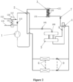
- Figure 2 is a schematic diagram of a flowing direction of carbon dioxide in a heating mode.
- the heating mode the exhaust end of the carbon dioxide compressor 1 and the multiple end heat exchangers 6 are communicated and the outdoor heat exchanger 3 and the suction end of the carbon dioxide compressor 1 are communicated through the first high-pressure four-way valve 2, the outdoor heat exchanger 3 and the liquid storage tank 5 are communicated and the liquid storage tank 5 and the multiple end heat exchangers 6 are communicated through the second high-pressure four-way valve 4.
- the carbon dioxide medium successively flows through the carbon dioxide compressor 1, the first high-pressure four-way valve 2, the multiple end heat exchangers 6, the liquid storage tank 5, the second high-pressure four-way valve 4, the first electronic expansion valve 7, and the outdoor heat exchanger 3 to perform heating.
- the second electronic expansion valve group 9 is opened to a maximum opening degree.
- the first electronic expansion valve 7 automatically adjusts an opening degree based on a predetermined superheat degree.
- the pressure in the liquid storage tank 5 is controlled to be constant by adjusting the opening degree of the third electronic expansion valve 101, so as to maintain the safe and efficient operation of the system.
- the single-stage carbon dioxide multi-split cooling and heating multifunctional central air conditioner differs from the conventional multi-split air conditioner.
- the conventional multi-split air conditioner generally uses a freon refrigeration system and a water circulation system being cascaded, and adjust temperature by using water circulation.
- using a single-stage carbon dioxide circulation can meet the requirements of multi-split central air conditioners and an evaporation temperature is controlled by controlling a suction pressure of the carbon dioxide compressor 1.
- the evaporation temperature may be controlled between 6 degrees Celsius and 10 degrees Celsius, thereby having a better physical effect.
- advantages of large pressure difference, good fluidity, and low density are achieved.
- the conventional refrigerant medium needs to be equipped with a circulating pump, which consumes energy and has a high cost.
- the efficiency can be increased by more than 2 times, and energy can be saved by more than 50%.
- the single-stage carbon dioxide multi-split cooling and heating multi-functional central air conditioner can be used for multiple purposes.
- the hot water supply device may be installed on the pipeline at the exhaust end of the carbon dioxide compressor 1 to generate domestic hot water.
- the air conditioner may be connected in series with the ice storage device.
- the air conditioner When using off-peak power to cool ice storage refrigerators, ice storage freezers or ice storage cold storages in buildings, for cold storages, refrigerators/cabinets and other low-temperature devices, the system efficiency is low and power consumption is large. To reduce the impact on the local power grid, the off-peak power is reasonably used by the cold storage technology.
- the air conditioner may be connected in series with the floor heating device.
- Carbon dioxide in the central air conditioner may also be used for fire-fighting or fire extinguishing. Carbon dioxide being used as a fire extinguishing medium reduces the cost of fire protection construction. Carbon dioxide being used for fire extinguishing causes no secondary damage to objects, having a natural advantage. For storage tanks with the same volume, the amount of carbon dioxide being stored in liquid is much larger than that being stored in gas, thereby achieving a larger fire extinguishing area.
- the carbon dioxide multi-split central air conditioner according to the present application is used for actual testing.
- an office area occupies an area of 2700m 2
- the number of the multiple end heat exchangers 6 is 82
- the outdoor heat exchanger 3 adopts a flash type enclosed heat exchanger.
- the outdoor heat exchanger 3 occupies an area of 2000m 2 , and only three 15-horsepower carbon dioxide compressors 1 with a condensation load of 200KW are required.
- the ambient temperature is 34 degrees Celsius and the evaporation pressure is 45bar
- the condensation pressure is stable and below 80bar, and a coefficient of performance cop of the system is in a range of 4.5 to 5.5.
- the coefficient of performance cop of the system may reach 6 at night, which is much higher than the coefficient of performance of the conventional freon system. According to experimental observations, the number of the multiple end heat exchangers driven by the carbon dioxide multi-split air condition may be hundreds of units.
- the central air conditioner further includes a pressure regulating device.
- the pressure regulating device includes a pressure regulating tank 100, the pressure regulating tank 100 is communicated with the liquid storage tank 5 through a pipeline, and the pressure regulating tank 100 is connected with a pipeline at the suction end of the carbon dioxide compressor 1.
- the pressure of the liquid storage tank 5 increases.
- the pressure in the liquid storage tank 5 is higher than a critical value, there will be non-liquid high-density gas in the liquid storage tank 5, the cooling capacity will be greatly reduced, and the increased pressure reduces the safety of the system.
- it is required to provide more pressure-resistant parts, which increases the manufacturing cost.
- the liquid storage tank 5 and the pressure regulating tank 100, the carbon dioxide compressor 1, and the outdoor heat exchanger 3 form a small cycle, which can reduce the pressure in the liquid storage tank 5 and further refrigerate.
- the pressure regulating tank 100 can store the refrigerant in liquid, so that the refrigerant in liquid will not enter the carbon dioxide compressor 1 rotating in a high-speed, thereby avoiding damage to the carbon dioxide compressor 1.
- the pressure regulating tank 100 has a second effect: when the central air conditioner is shut down for a long time in summer, the liquid in the liquid storage tank 5 changes in density due to heat absorption.
- the liquid storage tank 5 stores a liquid at 28 degrees Celsius (the density is 655.28kg/m 3 ) when the central air conditioner is shut down, and the pressure is a corresponding saturation pressure, when being shut down or being subjected to environmental thermal radiation, the pressure in the pipe reaches 35 degrees Celsius and 80bar, the density is about 419.09kg/m 3 .
- the pressure regulating tank 100 By arranging the pressure regulating tank 100, the problem of liquid expansion when the central air conditioner is shut down is solved.
- a third electronic expansion valve 101 is arranged between the pressure regulating tank 100 and the pipeline at the suction end of the carbon dioxide compressor 1.
- the pressure in the liquid storage tank 5 can be precisely controlled below a critical point, and the temperature in the tank is a saturation temperature corresponding to the tank pressure or has a certain subcooling temperature, and the system operates more efficiently.
- a bottom of the pressure regulating tank 100 is communicated with a top of the liquid storage tank 5, makes it easier for the gas in the liquid storage tank 5 to enter the pressure regulating tank 100.
- a top of the pressure regulating tank 100 is connected to the pipeline at the suction end of the carbon dioxide compressor 1.
- the central air conditioner further includes a hot water supply device connected to a pipeline at the exhaust end of the carbon dioxide compressor 1.
- the hot water supply device includes a water storage tank 110, a hot water pipe 111, a second one-way overflow valve 112, and a first solenoid valve 113, and the hot water pipe 111 are arranged in the water storage tank 110.
- Two ends of the hot water pipe 111 are connected with the pipeline at the exhaust end of the carbon dioxide compressor 1, and the second one-way overflow valve 112 is arranged at a pipeline at an outlet end of the hot water pipe 111, to avoid the backflow of the low-temperature carbon dioxide medium and act to control the pressure.
- the first solenoid valve 113 is arranged at the pipeline at the exhaust end of the carbon dioxide compressor 1, between positions at which the hot water pipe 111 is connected to the pipeline at the exhaust end of the carbon dioxide compressor 1.
- the first solenoid valve 113 is used to control whether to generate hot water.
- the water storage tank 110 includes a cold water inlet 114 and a hot water outlet 115, where cold water under a certain pressure enters the water storage tank 110 through the cold water inlet 114, and water in the water storage tank 110 exchanges heat through the hot water pipe 111 to generate hot water above 60 degrees Celsius.
- the hot water outlet 115 is connected to a domestic water pipeline.
- the first solenoid valve 113 In a case that hot water needs to be generated, the first solenoid valve 113 is closed, and the hot gas from the carbon dioxide compressor 1 passes through the hot water pipe 111 to prepare hot water, and then flows to the heat exchanger through the one-way overflow valve. In a case that the temperature of the hot water reaches a set requirement, the first solenoid valve 113 is opened, and the hot gas from the carbon dioxide compressor 1 flows directly to the outdoor heat exchanger 3.
- the hot water pipe 111 may be a coiled pipe or a finned pipe to increase the heat exchange area.
- the hot water supply device can cool down the hot gas of carbon dioxide, increase the heat exchange efficiency of the heat exchanger, and can provide domestic hot water, and also reduce the cooling burden on the refrigeration system, thereby being very energy efficient.
- the central air conditioner includes a floor heating device.
- the floor heating device includes a floor heating pipe 120 and a sixth solenoid valve 121.
- the sixth solenoid valve 121 is connected in series to a pipeline at the floor heating pipe 120.
- the floor heating device and the multiple end heat exchangers 6 are connected in parallel, and the carbon dioxide medium of the central air conditioner can circulate in the floor heating pipe 120.
- the first electronic expansion valve 7 automatically adjusts the opening degree based on a predetermined superheat degree to realize heating.
- the central air conditioner includes an ice storage device connected in parallel with the multiple end heat exchangers 6.
- the carbon dioxide medium of the central air conditioner can circulate in the ice storage device.
- the ice storage device includes one or more of ice storage refrigerators, ice storage freezers, and ice storage cold storages connected in parallel.
- a fourth electronic expansion valve group 130 is connected in series to a pipeline at the ice storage device, and automatically adjusts the opening degree based on a predetermined superheat degree to achieve cooling.
- a second solenoid valve 131 is arranged at an inlet pipeline of the ice storage device, and a third solenoid valve 132 is arranged at an outlet pipeline of the ice storage device.
- the outlet end of the ice storage device is connected to the suction end of the carbon dioxide compressor 1, and a fourth solenoid valve 133 is arranged at a pipeline for connecting the outlet end of the ice storage device to the suction end of the carbon dioxide compressor.
- the second solenoid valve 131, the third solenoid valve 132 and the fourth electronic expansion valve group 130 cooperate to realize the following functions. 1) The second solenoid valve 131, the third solenoid valve 132 and the fourth electronic expansion valve group 130 are opened in a case that refrigeration is required to be performed in the ice storage device, to realize the circulation of carbon dioxide refrigerant in the ice storage device.
- a cooling capacity required by the multiple end heat exchangers 6 is greatly reduced at night, and the second solenoid valve 131 and the fourth electronic expansion valve group 130 may be opened and the third solenoid valve 132 may be closed to store cold for the ice storage device.
- the system efficiency is low and power consumption is large.
- the off-peak power is reasonably used by the cold storage technology. That is, the second solenoid valve 131, the fourth solenoid valve 133, and the fourth electronic expansion valve group 130 are opened.
- the ice storage device and the outdoor heat exchanger are connected in parallel.
- the third solenoid valve 132 is closed, and the second solenoid valve 131 and the fourth solenoid valve 133 are opened.
- a carbon dioxide fire extinguishing device is connected to a circulation pipeline of the central air conditioner, and the carbon dioxide fire extinguishing device includes a fire-fighting pipeline 140 and a fifth solenoid valve 141 connected in series with the fire-fighting pipeline 140.
- the carbon dioxide in the refrigeration system is used as a fire-extinguishing medium to reduce the cost of fire protection construction.
- Carbon dioxide being used for fire extinguishing has no secondary damage to objects, having a natural advantage. For storage tanks with the same volume, the amount of carbon dioxide being stored in liquid is much larger than that being stored in gas, thereby achieving a larger fire extinguishing area.
- carbon dioxide has a characteristic of being difficult to burn and explode.
- the characteristic can be used to extinguish fires in building areas.
- the fifth solenoid valve 141 in the room and the second solenoid valve 131 at a main liquid supply pipeline are opened to allow liquid carbon dioxide to enter the room through a nozzle to extinguish the fire.
- the concentration in the room reaches a predetermined value, the second solenoid valve 131 and the fifth solenoid valve 141 are closed.
- the outdoor heat exchanger 3 includes an aerosol generating device (not shown in the figure) and a heat exchange pipe 150.
- the aerosol from the aerosol generating device enters the heat exchange chamber, and water microparticles in the aerosol gradually decompose from large microclusters to small microclusters when absorbing radiant heat of refrigerant in the heat exchange pipe 150.
- Carbon dioxide refrigerant is condensed and liquefied by absorbing heat in a process of the aerosol decomposing from large microclusters to small microclusters, and the aerosol decomposes from large microclusters to small microclusters in a dynamic and continuous manner.
- the aerosol generating device includes an enclosed housing, an air extraction device and a water atomization device.
- the air extraction device is used to form a negative pressure in the enclosed housing
- the water atomization device is used to atomize liquid water into water mist with a larger specific surface area.
- the atomized water and air form the aerosol in the enclosed housing under the negative pressure, and the aerosol enters the heat exchange pipe 150 from an aerosol inlet 151 for heat exchanging.
- the water obtained after heat exchanging is not circulated and recycled, and is directly discharged into the atmosphere through an aerosol outlet 152. Since the heat is mainly converted into internal energy during the decomposition process of the aerosol, the temperature of the discharged water mist is not high, and no heat island effect will occur.
- the high-temperature carbon dioxide in the heat exchange pipe 150 of the present application is a heat exchange mode in which small microclusters in the aerosol are decomposed by using the radiant heat and heat is taken away, thereby greatly improving the heat exchange efficiency.
- the aerosol gradually decomposes from large microclusters into small microclusters with being subjected to the radiation heat, to perform heat exchange.
- the heat exchange is not affected by high temperature and high humidity conditions, and can be used normally under different climatic conditions.
- mist droplets since the volume of water atomized into mist droplets becomes smaller, it is easier to disperse and float, which speeds up the fluidity of the mist droplets and heat exchange with the outdoor heat exchanger 3 can be quickly performed. In addition, most of the mist droplets with a small volume in the direct-contact heat exchange process absorb heat and evaporate into vapor, thereby greatly improving the coefficient of performance.
- an inner wall of the enclosed housing and/or a surface of the heat exchange pipe is coated with a water-repellent agent.
- the water-repellent agent is a pollution-free and harmless super-hydrophobic material, and is used to prevent huge water droplets formed by collision and combination of the sprayed-out small water drops from attaching to the inner wall of the enclosed housing and the surface of the heat exchanger, to prevent the water droplets from hanging on the inner wall and the surface and prevent the heat exchange efficiency from being affected.
- orientation or positional relationships indicated by terms such as “front/back”, “up/down”, “left/right”, “vertical/horizontal”, “inner/outer” and the like are based on the orientation or positional relationships shown in the drawings, and are merely for the convenience of describing the present application and the simplification of the description, and do not indicate or imply that the device or element referred to must have a particular orientation, or be configured and operated in a particular orientation, and therefore should not be construed as a limitation to the scope of the present application.
- terms such as “first”, “second”, “third” and the like are merely for description, and should not be construed as indicating or implying relative importance.
- the "left”, “right”, “up” and “down” referred to below are consistent with the left, right, up, and down directions of the drawings, but they do not limit the structure of the present application.
Landscapes
- Engineering & Computer Science (AREA)
- General Engineering & Computer Science (AREA)
- Mechanical Engineering (AREA)
- Chemical & Material Sciences (AREA)
- Thermal Sciences (AREA)
- Physics & Mathematics (AREA)
- Combustion & Propulsion (AREA)
- Life Sciences & Earth Sciences (AREA)
- Sustainable Development (AREA)
- Chemical Kinetics & Catalysis (AREA)
- Health & Medical Sciences (AREA)
- Public Health (AREA)
- Business, Economics & Management (AREA)
- Emergency Management (AREA)
- Other Air-Conditioning Systems (AREA)
- Central Air Conditioning (AREA)
- Air-Conditioning Room Units, And Self-Contained Units In General (AREA)
- Compression-Type Refrigeration Machines With Reversible Cycles (AREA)
Abstract
A single-stage carbon dioxide multi-split cooling and heating multifunctional central air conditioner, comprising a single-stage carbon dioxide circulation system using carbon dioxide as a circulation working medium; the single-stage carbon dioxide circulation system comprises an outdoor unit and a plurality of end heat exchangers (6) provided in parallel; and the carbon dioxide medium performs cooling and/or heating in a circulating manner in a carbon dioxide compressor (1), an outdoor heat exchanger (3), a liquid storage tank (5) and the end heat exchangers (6) which are in communication with one another. By using carbon dioxide as a circulation working medium, said central air conditioner has the advantages of large pressure difference, good flowability and low density, can be used in high-rise buildings, and can perform circulation at a height of 100 meters or more. A hot water supply apparatus is provided on a pipeline at an exhaust end of the carbon dioxide compressor (1), an ice storage device and a floor heating apparatus are connected in series to the pipeline at the exhaust end of the carbon dioxide compressor, and carbon dioxide in said system can also be used for fire fighting and fire extinguishing, achieving multiple purposes of said central air conditioner.
Description
- The present application relates to the field of air conditioning, in particular to a single-stage carbon dioxide multi-split cooling and heating multifunctional central air conditioner.
- A central air conditioner may be installed in different areas and controlled for each of areas, and operate independently in each room for adjusting air in the areas respectively. The central air conditioner has advantages of high efficiency and energy saving, good comfort, beautiful appearance, and quiet operation, and has been more and more widely used. A multi-split mode is characterized by energy saving, low operating cost, reliable operation, good unit adaptability, and wide cooling and heating temperature range, and is suitable for commercial and civil use.
- Traditional multi-split central air conditioner uses freon as a refrigeration working medium. Due to the characteristics of high density, high viscosity and small pressure difference of the freon, the traditional multi-split central air conditioner has the following defects. 1) A small number of end heat exchangers are driven, according to experience, the number of air disks of the end heat exchangers generally is less than 10, and in usage scenarios with more independent spaces, the number of outdoor units may inevitably increase, resulting in higher costs, inconvenient installation, and high maintenance costs. 2) Due to the high viscosity of freon, an indoor unit and an outdoor unit are installed with a small drop, and a piping distance is short, limiting the scope of use. 3) Heating in winter is greatly affected by the climate, in a case that an ambient temperature is lower than -5 degrees Celsius, the thermal efficiency decreases seriously, and the air conditioner may even not operate normally. Therefore, the current multi-split air conditioner is not very effective in a low-temperature heating project. In order to maintain a heating effect, the indoor unit is usually equipped with an auxiliary electric heater, which is automatically put into use, thereby energy consumption is increased. 4) The price of freon refrigerant is high, and the maintenance costs are relatively high. 5) Freon is not environmentally friendly, and the discharge of Freon into the atmosphere leads to a decrease of ozone content, causing creatures on the earth to be severely damaged by ultraviolet rays. In addition, freon, as a kind of greenhouse gas, results in an increase in temperatures in the lower stratosphere and in the troposphere. Therefore, methods and technologies for solving a problem of freon pollution are researched on. The ways to solve the problem of environmental pollution mainly include restriction and prohibition, development of substitutes and harmlessness of freon. With the increasing attention of the international community to energy conservation, emission reduction and environmental protection, the elimination of freon refrigerants has accelerated. As a safe and environmentally friendly refrigerant, carbon dioxide has a broad application prospect and considerable economic value. The applicant is committed to the research of using carbon dioxide as a refrigerant. After years of research, the use of carbon dioxide as a refrigerant can be used in the field of central air conditioners.
- To sum up, it is a motivation of the present application to provide a carbon dioxide multi-split air conditioner which uses carbon dioxide as a circulating working medium of the air conditioner, has a simple structure, a low cost and a high efficiency, and is environmentally friendly.
- The object of the present application is to overcome the deficiencies of the conventional technology, and provide a single-stage carbon dioxide multi-split cooling and heating multifunctional central air conditioner which uses carbon dioxide as a circulating working medium of the air conditioner, has a simple structure, a high efficiency and a low cost, and is environmentally friendly. In view of the fact that the multi-split air conditioner system according to the present application uses carbon dioxide, a natural and environmentally friendly working medium, as single refrigeration working medium, a large number of end heat exchangers are driven due to a low density, low viscosity and large pressure difference of carbon dioxide.
- The technical solutions of the single-stage carbon dioxide multi-split cooling and heating multifunctional central air conditioner according to the present application are described as follows.
- A single-stage carbon dioxide multi-split cooling and heating multifunctional central air conditioner is provided according to an embodiment of the present application. The central air conditioner includes: a single-stage carbon dioxide circulation system using a single carbon dioxide as a circulating working medium, where the single-stage carbon dioxide circulation system includes an outdoor unit and multiple end heat exchangers arranged in parallel, and cooling and/or heating is performed by carbon dioxide medium circulating in a carbon dioxide compressor, an outdoor heat exchanger, a liquid storage tank, and the multiple end heat exchangers that are communicated with each other.
- In an embodiment, the carbon dioxide compressor, the outdoor heat exchanger and the liquid storage tank constitute the outdoor unit for providing refrigerant or heat medium, each of the multiple end heat exchangers is arranged indoors for adjusting a temperature in a space, one outdoor unit is configured to tow 30 or more indoor units, the carbon dioxide medium is capable of circulating in a high-rise building at a height of 100 meters or more, and a coefficient of performance cop of the central air conditioner is greater than 4.5.
- In an embodiment, the central air conditioner includes a first high-pressure four-way valve and a second high-pressure four-way valve, four ports of the first high-pressure four-way valve are respectively connected to a suction end of the carbon dioxide compressor, an exhaust end of the carbon dioxide compressor, the outdoor heat exchanger, and the multiple end heat exchangers; and four ports of the second high-pressure four-way valve are respectively connected to the outdoor heat exchanger, a liquid inlet of the liquid storage tank, a liquid outlet of the liquid storage tank, and the multiple end heat exchangers.
- In an embodiment, a first one-way overflow valve is arranged at a pipeline between the liquid storage tank and the second high-pressure four-way valve.
- In an embodiment, a first electronic expansion valve is arranged at a pipeline between the outdoor heat exchanger and the liquid storage tank, and a second electronic expansion valve group is connected in series to pipelines at the multiple end heat exchangers.
- In an embodiment, in a cooling mode, the exhaust end of the carbon dioxide compressor and an suction end of the outdoor heat exchanger are communicated and an outlet end of each of the multiple end heat exchangers and the suction end of the carbon dioxide compressor are communicated through the first high-pressure four-way valve, an outlet end of the outdoor heat exchanger and the liquid inlet of the liquid storage tank are communicated and the liquid outlet of the liquid storage tank and an inlet end of each of the multiple end heat exchangers are communicated through the second high-pressure four-way valve, and the carbon dioxide medium successively flows through the carbon dioxide compressor, the first high-pressure four-way valve, the outdoor heat exchanger, the first electronic expansion valve, the second high-pressure four-way valve, the first one-way overflow valve, the liquid storage tank, the second electronic expansion valve group, and the multiple end heat exchangers to perform cooling, and when cooling is performed, an evaporation temperature is controlled between 6 degrees Celsius and 10 degrees Celsius to obtain a good physical effect.
- In a heating mode, the exhaust end of the carbon dioxide compressor and the multiple end heat exchangers are communicated and the outdoor heat exchanger and the suction end of the carbon dioxide compressor are communicated through the first high-pressure four-way valve, the outdoor heat exchanger and the liquid storage tank are communicated and the liquid storage tank and the multiple end heat exchangers are communicated through the second high-pressure four-way valve, and the carbon dioxide medium successively flows through the carbon dioxide compressor, the first high-pressure four-way valve, the multiple end heat exchangers, the liquid storage tank, the second high-pressure four-way valve, the first electronic expansion valve, and the outdoor heat exchanger to perform heating.
- In an embodiment, the central air conditioner further includes a pressure regulating device including a pressure regulating tank, where the pressure regulating tank is communicated with the liquid storage tank through a pipeline, and the pressure regulating tank is connected with a pipeline at the suction end of the carbon dioxide compressor.
- In an embodiment, a third electronic expansion valve is arranged between the pressure regulating tank and the pipeline at the suction end of the carbon dioxide compressor, and a bottom of the pressure regulating tank is communicated with a top of the liquid storage tank, and a top of the pressure regulating tank is connected to the pipeline at the suction end of the carbon dioxide compressor.
- In an embodiment, the central air conditioner further includes a hot water supply device connected to a pipeline at the exhaust end of the carbon dioxide compressor.
- In an embodiment, the hot water supply device includes a water storage tank, a hot water pipe, a second one-way overflow valve, and a first solenoid valve, the hot water pipe is arranged in the water storage tank, two ends of the hot water pipe are connected with the pipeline at the exhaust end of the carbon dioxide compressor, the second one-way overflow valve is arranged at a pipeline at an outlet end of the hot water pipe, the first solenoid valve is arranged at the pipeline at the exhaust end of the carbon dioxide compressor, between positions at which the hot water pipe is connected to the pipeline at the exhaust end of the carbon dioxide compressor, the first solenoid valve is used to control whether to generate hot water, the water storage tank includes a cold water inlet and a hot water outlet, where cold water under a certain pressure enters the water storage tank through the cold water inlet, and water in the water storage tank exchanges heat through the hot water pipe to generate hot water.
- In an embodiment, the central air conditioner includes a floor heating device, the floor heating device includes a floor heating pipe and a sixth solenoid valve, the sixth solenoid valve is connected in series to a pipeline of the floor heating pipe, and the floor heating device is connected in parallel with the multiple end heat exchangers.
- In an embodiment, the central air conditioner includes an ice storage device connected in parallel with the multiple end heat exchangers, and the ice storage device includes one or more of ice storage refrigerators, ice storage freezers or ice storage cold storages connected in parallel.
- In an embodiment, a fourth electronic expansion valve group is connected in series to a pipeline at the ice storage device, a second solenoid valve is arranged at an inlet pipeline of the ice storage device, a third solenoid valve is arranged at an outlet pipeline of the ice storage device, an outlet end of the ice storage device is connected to the suction end of the carbon dioxide compressor, and a fourth solenoid valve is arranged at a pipeline for connecting the outlet end of the ice storage device to the suction end of the carbon dioxide compressor.
- In an embodiment, a carbon dioxide fire extinguishing device is connected at a circulation pipeline of the central air conditioner, and the carbon dioxide fire extinguishing device includes a fire-fighting pipeline and a fifth solenoid valve connected in series to the fire-fighting pipeline, where the fire-fighting pipeline is connected to a carbon dioxide circulation pipeline.
- In an embodiment, the outdoor heat exchanger includes an aerosol generating device and a heat exchange pipe, aerosol in the aerosol generating device enters a heat exchanger chamber, water microclusters in the aerosol gradually decompose from large microclusters to small microclusters when absorbing radiated heat of refrigerant in the heat exchange pipe, where carbon dioxide refrigerant is condensed and liquefied by absorbing heat in a process of the aerosol decomposing from large microclusters to small microclusters, and the aerosol decomposes from large microclusters to small microclusters in a dynamic and continuous manner.
- In an embodiment, the aerosol generating device includes an enclosed housing, an air extraction device and a water atomization device, the air extraction device is used to form a negative pressure in the enclosed housing, the water atomization device is used to atomize liquid water into water mist with a larger specific surface area, the atomized water and air form an aerosol in the enclosed housing under the negative pressure, the aerosol enters the heat exchange chamber for heat exchanging, and water obtained after heat exchanging is directly discharged into an atmosphere.
- In an embodiment, an inner wall of the enclosed housing and/or a surface of the heat exchange pipe is coated with a water-repellent agent to prevent water droplets from hanging on the inner wall or the surface.
- Embodiments of the present application have the following technical effects.
- The single-stage carbon dioxide multi-split cooling and heating multifunctional central air conditioner according to the present application differs from from the conventional multi-split air conditioners. The conventional multi-split air conditioners generally use a freon refrigeration system and a water circulation system being cascaded, and adjust temperature by using water circulation. In the present application, using a single-stage carbon dioxide circulation can meet the requirements of multi-split central air conditioners and an evaporation temperature is controlled by controlling a suction pressure of the carbon dioxide compressor. For example, the evaporation temperature may be controlled between 6 degrees Celsius and 10 degrees Celsius, thereby having a better physical effect. In view of the use of carbon dioxide as a circulating working medium, advantages of large pressure difference, good fluidity, low density, and transcritical phase transition are achieved. It can be used in high-rise buildings and circulate at a height of 100 meters or more, which cannot be achieved by the conventional freon multi-split central air conditioners. In addition, the conventional refrigerant medium needs to be equipped with a circulating pump, which consumes energy and has a high cost. Compared with the conventional air conditioners, with the central air conditioner according to the present application, the efficiency can be increased by more than 2 times, and energy can be saved by more than 50%.
- The single-stage carbon dioxide multi-split cooling and heating multi-functional central air conditioner according to the present application can be used for multiple purposes. The hot water supply device may be installed on the pipeline at the exhaust end of the carbon dioxide compressor to generate domestic hot water. The air conditioner may be connected in series with the ice storage device. When using off-peak power to cool ice storage refrigerators, ice storage freezers or ice storage cold storages in buildings, for cold storages, refrigerators/cabinets and other low-temperature devices, the system efficiency is low and power consumption is large. To reduce the impact on the local power grid, the off-peak power is reasonably used by the cold storage technology. The air conditioner may be connected in series with the floor heating device. Carbon dioxide in the central air conditioner may also be used for fire-fighting or fire extinguishing. Carbon dioxide being used as a fire-fighting or fire extinguishing medium reduces the cost of fire protection construction. Carbon dioxide being used for fire extinguishing causes no secondary damage to objects, having a natural advantage. For storage tanks with the same volume, the amount of carbon dioxide being stored in liquid is much larger than that being stored in gas, thereby achieving a larger fire extinguishing area.
-
-
Figure 1 is a schematic system diagram of a single-stage carbon dioxide multi-split cooling and heating multifunctional central air conditioner in a cooling mode according to an embodiment of the present application. -
Figure 2 is a schematic system diagram of a single-stage carbon dioxide multi-split cooling and heating multifunctional central air conditioner in a heating mode according to an embodiment of the present application. -
Figure 3 is a schematic system diagram of a central air conditioner, in which a floor heating device, an ice storage device, and a fire-extinguishing device are included, in a cooling mode. -
Figure 4 is a schematic system diagram of a central air conditioner, in which a floor heating device, an ice storage device, and a fire-extinguishing device are included, in a heating mode. - The following reference numerals are referred to in
Figures 1 to 4 .
1. carbon dioxide compressor; 2. first high-pressure four-way valve; 3. outdoor heat exchanger; 4. second high-pressure four-way valve; 5. liquid storage tank; 6. end heat exchanger; 7. first electronic expansion valve; 8. first one-way overflow valve; 9. second electronic expansion valve group; 100. pressure regulating tank; 101. third electronic expansion valve; 110. water storage tank; 111. hot water pipe; 112. second one-way overflow valve; 113. first solenoid valve; 114. cold water inlet; 115. hot water outlet; 120. floor heating pipe; 121. sixth solenoid valve; 130. fourth electronic expansion valve group; 131. second solenoid valve; 132. third solenoid valve; 133. fourth solenoid valve; 140. fire-fighting pipeline; 141. fifth solenoid valve; 150. heat exchange pipe; 151. aerosol inlet; and 152. aerosol outlet. - The present application is described in detail hereinafter in conjunction with the embodiments and the accompanying drawings. It should be noted that the described embodiments are only intended to facilitate the understanding of the present application, rather than limiting the present application in any way.
- Referring to
Figures 1 to 4 , a single-stage carbon dioxide multi-split cooling and heating multifunctional central air conditioner according to an embodiment includes a single-stage carbon dioxide circulation system using carbon dioxide as a circulating working medium. The single-stage carbon dioxide circulation system includes an outdoor unit and multiple end heat exchangers 6 (indoor units) arranged in parallel. Cooling and/or heating is performed by carbon dioxide medium circulating in acarbon dioxide compressor 1, anoutdoor heat exchanger 3, a liquid storage tank 5, and the multipleend heat exchangers 6 that are communicated with each other. Further, the central air conditioner includes a first high-pressure four-way valve 2 and a second high-pressure four-way valve 4. Four ports of the first high-pressure four-way valve 2 are respectively connected to a suction end of thecarbon dioxide compressor 1, an exhaust end of thecarbon dioxide compressor 1, theoutdoor heat exchanger 3, and the multipleend heat exchangers 6. Four ports of the second high-pressure four-way valve 4 are respectively connected to theoutdoor heat exchanger 3, a liquid inlet of the liquid storage tank 5, a liquid outlet of the liquid storage tank 5, and the multipleend heat exchangers 6. A reversing of the cooling and the heating can be realized. The single-stage is defined to differ from a cascaded system, and only carbon dioxide is used for circulation without being cascaded. - The
carbon dioxide compressor 1, theoutdoor heat exchanger 3 and the liquid storage tank 5 may constitute the outdoor unit for providing refrigerant or heat medium, and each of the multipleend heat exchangers 6 is arranged indoors for adjusting a temperature in a space. The carbon dioxide medium is capable of circulating in a high-rise building at a height of 100 meters or more. A coefficient of performance cop of the central air conditioner is greater than 4.5. One outdoor unit is configured to tow more than 30 indoor units, and 100 indoor units or more at most. - The carbon dioxide medium is capable of circulating in a high-rise building at a height of 100 meters or more. The coefficient of performance cop of the central air conditioner is greater than 4.5. Carbon dioxide, having a GWP of 1 and an ODP of 0, is an environmentally friendly refrigerant. Carbon dioxide has good safety and chemical stability, is non-toxic, non-flammable, and suitable for various lubricants. Carbon dioxide has good thermal properties, large cooling capacity per unit volume, low kinematic viscosity, and excellent flow and heat transfer characteristics. However, due to the low critical temperature (31.1 degrees Celsius) of carbon dioxide, it is easier to maintain in a gaseous state at an ambient temperature in summer. The critical pressure is high (7.38MPa), and the pressure in the gaseous state is high, which results in high operating pressure and a large throttling loss of a system. Based on the characteristics of carbon dioxide, with the technical solutions of the present application, it can be ensured that the pressure in the central air conditioner is maintained within an appropriate range, and that carbon dioxide is in a liquid state at an outlet of the outdoor heat exchanger, so that the heat exchange effect in the multiple
end heat exchangers 6 is better, and one host can tow more (more than 100)end heat exchangers 6, and the system is ensured to operate safely and normally. - Referring to
Figure 1 , a first one-way overflow valve 8 is arranged at a pipeline between the liquid storage tank 5 and the second high-pressure four-way valve 4. The first one-way overflow valve 8 only allows to flow in one direction, and also has a function of pressure regulation, so that the pressure in the central air conditioner can always be maintained in an appropriate range, so as to ensure the efficient operation of the system. A firstelectronic expansion valve 7 is arranged at a pipeline between theoutdoor heat exchanger 3 and the liquid storage tank 5, thereby throttling and reducing pressure. A second electronicexpansion valve group 9 is connected in series to pipelines of theend heat exchangers 6, thereby throttling and reducing pressure. -
Figure 1 is a schematic diagram of a flowing direction of carbon dioxide in a cooling mode. In the cooling mode, the exhaust end of thecarbon dioxide compressor 1 and an suction end of theoutdoor heat exchanger 3 are communicated and an outlet end of each of the multiple end heat exchangers and the suction end of thecarbon dioxide compressor 1 are communicated through the first high-pressure four-way valve 2, an outlet end of theoutdoor heat exchanger 3 and the liquid inlet of the liquid storage tank 5 are communicated and the liquid outlet of the liquid storage tank 5 and an inlet end of each of the multipleend heat exchangers 6 are communicated through the second high-pressure four-way valve 4. The carbon dioxide medium successively flows through thecarbon dioxide compressor 1, the first high-pressure four-way valve 2, theoutdoor heat exchanger 3, the firstelectronic expansion valve 7, the second high-pressure four-way valve 4, the first one-way overflow valve 8, the liquid storage tank 5, the second electronicexpansion valve group 9, and the multipleend heat exchangers 6 to perform cooling. In the cooling mode, the firstelectronic expansion valve 7 is opened to a maximum opening degree. The second electronicexpansion valve group 9 automatically adjusts an opening degree based on a predetermined superheat degree. The pressure in the liquid storage tank 5 is controlled to be constant by adjusting the opening degree of the thirdelectronic expansion valve 101, so as to maintain the safe and efficient operation of the system. -
Figure 2 is a schematic diagram of a flowing direction of carbon dioxide in a heating mode. In the heating mode, the exhaust end of thecarbon dioxide compressor 1 and the multipleend heat exchangers 6 are communicated and theoutdoor heat exchanger 3 and the suction end of thecarbon dioxide compressor 1 are communicated through the first high-pressure four-way valve 2, theoutdoor heat exchanger 3 and the liquid storage tank 5 are communicated and the liquid storage tank 5 and the multipleend heat exchangers 6 are communicated through the second high-pressure four-way valve 4. The carbon dioxide medium successively flows through thecarbon dioxide compressor 1, the first high-pressure four-way valve 2, the multipleend heat exchangers 6, the liquid storage tank 5, the second high-pressure four-way valve 4, the firstelectronic expansion valve 7, and theoutdoor heat exchanger 3 to perform heating. In the heating mode, the second electronicexpansion valve group 9 is opened to a maximum opening degree. The firstelectronic expansion valve 7 automatically adjusts an opening degree based on a predetermined superheat degree. The pressure in the liquid storage tank 5 is controlled to be constant by adjusting the opening degree of the thirdelectronic expansion valve 101, so as to maintain the safe and efficient operation of the system. - The single-stage carbon dioxide multi-split cooling and heating multifunctional central air conditioner according to the present application differs from the conventional multi-split air conditioner. The conventional multi-split air conditioner generally uses a freon refrigeration system and a water circulation system being cascaded, and adjust temperature by using water circulation. In the present application, using a single-stage carbon dioxide circulation can meet the requirements of multi-split central air conditioners and an evaporation temperature is controlled by controlling a suction pressure of the
carbon dioxide compressor 1. For example, the evaporation temperature may be controlled between 6 degrees Celsius and 10 degrees Celsius, thereby having a better physical effect. In view of the use of carbon dioxide as a circulating working medium, advantages of large pressure difference, good fluidity, and low density are achieved. It can be used in high-rise buildings and circulates at a height of 100 meters or more, which cannot be achieved by the conventional freon multi-split central air conditioner. In addition, the conventional refrigerant medium needs to be equipped with a circulating pump, which consumes energy and has a high cost. Compared with the conventional air conditioner, with the central air conditioner according to the present application, the efficiency can be increased by more than 2 times, and energy can be saved by more than 50%. - Referring to
Figure 3 andFigure 4 , the single-stage carbon dioxide multi-split cooling and heating multi-functional central air conditioner according to the present application can be used for multiple purposes. The hot water supply device may be installed on the pipeline at the exhaust end of thecarbon dioxide compressor 1 to generate domestic hot water. The air conditioner may be connected in series with the ice storage device. When using off-peak power to cool ice storage refrigerators, ice storage freezers or ice storage cold storages in buildings, for cold storages, refrigerators/cabinets and other low-temperature devices, the system efficiency is low and power consumption is large. To reduce the impact on the local power grid, the off-peak power is reasonably used by the cold storage technology. The air conditioner may be connected in series with the floor heating device. Carbon dioxide in the central air conditioner may also be used for fire-fighting or fire extinguishing. Carbon dioxide being used as a fire extinguishing medium reduces the cost of fire protection construction. Carbon dioxide being used for fire extinguishing causes no secondary damage to objects, having a natural advantage. For storage tanks with the same volume, the amount of carbon dioxide being stored in liquid is much larger than that being stored in gas, thereby achieving a larger fire extinguishing area. - The carbon dioxide multi-split central air conditioner according to the present application is used for actual testing. According to the data used in an actual engineering test, an office area occupies an area of 2700m2, the number of the multiple
end heat exchangers 6 is 82, and theoutdoor heat exchanger 3 adopts a flash type enclosed heat exchanger. Theoutdoor heat exchanger 3 occupies an area of 2000m2, and only three 15-horsepowercarbon dioxide compressors 1 with a condensation load of 200KW are required. When the ambient temperature is 34 degrees Celsius and the evaporation pressure is 45bar, the condensation pressure is stable and below 80bar, and a coefficient of performance cop of the system is in a range of 4.5 to 5.5. The coefficient of performance cop of the system may reach 6 at night, which is much higher than the coefficient of performance of the conventional freon system. According to experimental observations, the number of the multiple end heat exchangers driven by the carbon dioxide multi-split air condition may be hundreds of units. - Referring to
Figure 3 , the central air conditioner further includes a pressure regulating device. The pressure regulating device includes apressure regulating tank 100, thepressure regulating tank 100 is communicated with the liquid storage tank 5 through a pipeline, and thepressure regulating tank 100 is connected with a pipeline at the suction end of thecarbon dioxide compressor 1. With the operation of the system, the pressure of the liquid storage tank 5 increases. In a case that the pressure in the liquid storage tank 5 is higher than a critical value, there will be non-liquid high-density gas in the liquid storage tank 5, the cooling capacity will be greatly reduced, and the increased pressure reduces the safety of the system. On the other hand, it is required to provide more pressure-resistant parts, which increases the manufacturing cost. With the above structure, in a case that the pressure in the liquid storage tank 5 is too high, the liquid storage tank 5 and thepressure regulating tank 100, thecarbon dioxide compressor 1, and theoutdoor heat exchanger 3 form a small cycle, which can reduce the pressure in the liquid storage tank 5 and further refrigerate. In addition, thepressure regulating tank 100 can store the refrigerant in liquid, so that the refrigerant in liquid will not enter thecarbon dioxide compressor 1 rotating in a high-speed, thereby avoiding damage to thecarbon dioxide compressor 1. Thepressure regulating tank 100 has a second effect: when the central air conditioner is shut down for a long time in summer, the liquid in the liquid storage tank 5 changes in density due to heat absorption. For example, the liquid storage tank 5 stores a liquid at 28 degrees Celsius (the density is 655.28kg/m3) when the central air conditioner is shut down, and the pressure is a corresponding saturation pressure, when being shut down or being subjected to environmental thermal radiation, the pressure in the pipe reaches 35 degrees Celsius and 80bar, the density is about 419.09kg/m3. According to the principle of conservation of mass, additional space is required for storage of the expanding fluid. By arranging thepressure regulating tank 100, the problem of liquid expansion when the central air conditioner is shut down is solved. A thirdelectronic expansion valve 101 is arranged between thepressure regulating tank 100 and the pipeline at the suction end of thecarbon dioxide compressor 1. By arranging the thirdelectronic expansion valve 101, the pressure in the liquid storage tank 5 can be precisely controlled below a critical point, and the temperature in the tank is a saturation temperature corresponding to the tank pressure or has a certain subcooling temperature, and the system operates more efficiently. In an embodiment, a bottom of thepressure regulating tank 100 is communicated with a top of the liquid storage tank 5, makes it easier for the gas in the liquid storage tank 5 to enter thepressure regulating tank 100. A top of thepressure regulating tank 100 is connected to the pipeline at the suction end of thecarbon dioxide compressor 1. - Referring to
Figures 3 and4 , the central air conditioner further includes a hot water supply device connected to a pipeline at the exhaust end of thecarbon dioxide compressor 1. The hot water supply device includes awater storage tank 110, ahot water pipe 111, a second one-way overflow valve 112, and afirst solenoid valve 113, and thehot water pipe 111 are arranged in thewater storage tank 110. Two ends of thehot water pipe 111 are connected with the pipeline at the exhaust end of thecarbon dioxide compressor 1, and the second one-way overflow valve 112 is arranged at a pipeline at an outlet end of thehot water pipe 111, to avoid the backflow of the low-temperature carbon dioxide medium and act to control the pressure. Thefirst solenoid valve 113 is arranged at the pipeline at the exhaust end of thecarbon dioxide compressor 1, between positions at which thehot water pipe 111 is connected to the pipeline at the exhaust end of thecarbon dioxide compressor 1. Thefirst solenoid valve 113 is used to control whether to generate hot water. Thewater storage tank 110 includes acold water inlet 114 and ahot water outlet 115, where cold water under a certain pressure enters thewater storage tank 110 through thecold water inlet 114, and water in thewater storage tank 110 exchanges heat through thehot water pipe 111 to generate hot water above 60 degrees Celsius. Thehot water outlet 115 is connected to a domestic water pipeline. In a case that hot water needs to be generated, thefirst solenoid valve 113 is closed, and the hot gas from thecarbon dioxide compressor 1 passes through thehot water pipe 111 to prepare hot water, and then flows to the heat exchanger through the one-way overflow valve. In a case that the temperature of the hot water reaches a set requirement, thefirst solenoid valve 113 is opened, and the hot gas from thecarbon dioxide compressor 1 flows directly to theoutdoor heat exchanger 3. Thehot water pipe 111 may be a coiled pipe or a finned pipe to increase the heat exchange area. It should be noted that in a case that the central air conditioner needs to perform refrigeration, the hot water supply device can cool down the hot gas of carbon dioxide, increase the heat exchange efficiency of the heat exchanger, and can provide domestic hot water, and also reduce the cooling burden on the refrigeration system, thereby being very energy efficient. - Referring to
Figure 3 andFigure 4 , the central air conditioner includes a floor heating device. The floor heating device includes afloor heating pipe 120 and asixth solenoid valve 121. Thesixth solenoid valve 121 is connected in series to a pipeline at thefloor heating pipe 120. The floor heating device and the multipleend heat exchangers 6 are connected in parallel, and the carbon dioxide medium of the central air conditioner can circulate in thefloor heating pipe 120. In a case that thesixth solenoid valve 121 is opened, the firstelectronic expansion valve 7 automatically adjusts the opening degree based on a predetermined superheat degree to realize heating. - Referring to
Figure 3 andFigure 4 , the central air conditioner includes an ice storage device connected in parallel with the multipleend heat exchangers 6. The carbon dioxide medium of the central air conditioner can circulate in the ice storage device. The ice storage device includes one or more of ice storage refrigerators, ice storage freezers, and ice storage cold storages connected in parallel. A fourth electronicexpansion valve group 130 is connected in series to a pipeline at the ice storage device, and automatically adjusts the opening degree based on a predetermined superheat degree to achieve cooling. Asecond solenoid valve 131 is arranged at an inlet pipeline of the ice storage device, and a third solenoid valve 132 is arranged at an outlet pipeline of the ice storage device. The outlet end of the ice storage device is connected to the suction end of thecarbon dioxide compressor 1, and afourth solenoid valve 133 is arranged at a pipeline for connecting the outlet end of the ice storage device to the suction end of the carbon dioxide compressor. Thesecond solenoid valve 131, the third solenoid valve 132 and the fourth electronicexpansion valve group 130 cooperate to realize the following functions. 1) Thesecond solenoid valve 131, the third solenoid valve 132 and the fourth electronicexpansion valve group 130 are opened in a case that refrigeration is required to be performed in the ice storage device, to realize the circulation of carbon dioxide refrigerant in the ice storage device. 2) A cooling capacity required by the multipleend heat exchangers 6 is greatly reduced at night, and thesecond solenoid valve 131 and the fourth electronicexpansion valve group 130 may be opened and the third solenoid valve 132 may be closed to store cold for the ice storage device. When using off-peak power to cool ice storage refrigerators, ice storage freezers or ice storage cold storages in buildings, for cold storages, refrigerators/cabinets and other low-temperature devices, the system efficiency is low and power consumption is large. To reduce the impact on the local power grid, the off-peak power is reasonably used by the cold storage technology. That is, thesecond solenoid valve 131, thefourth solenoid valve 133, and the fourth electronicexpansion valve group 130 are opened. When heating at the end of the air conditioner or heating at the floor, and the off-peak power is still needed to cool the ice storage device at night, the ice storage device and the outdoor heat exchanger are connected in parallel. In this case, the third solenoid valve 132 is closed, and thesecond solenoid valve 131 and thefourth solenoid valve 133 are opened. - Referring to
Figure 3 andFigure 4 , a carbon dioxide fire extinguishing device is connected to a circulation pipeline of the central air conditioner, and the carbon dioxide fire extinguishing device includes a fire-fighting pipeline 140 and afifth solenoid valve 141 connected in series with the fire-fighting pipeline 140. The carbon dioxide in the refrigeration system is used as a fire-extinguishing medium to reduce the cost of fire protection construction. Carbon dioxide being used for fire extinguishing has no secondary damage to objects, having a natural advantage. For storage tanks with the same volume, the amount of carbon dioxide being stored in liquid is much larger than that being stored in gas, thereby achieving a larger fire extinguishing area. As a natural working medium, carbon dioxide has a characteristic of being difficult to burn and explode. The characteristic can be used to extinguish fires in building areas. When it is judged by a smoke sensor or temperature sensor in a room that a fire has occurred, thefifth solenoid valve 141 in the room and thesecond solenoid valve 131 at a main liquid supply pipeline are opened to allow liquid carbon dioxide to enter the room through a nozzle to extinguish the fire. In a case that the concentration in the room reaches a predetermined value, thesecond solenoid valve 131 and thefifth solenoid valve 141 are closed. - Referring to
Figure 3 andFigure 4 , theoutdoor heat exchanger 3 includes an aerosol generating device (not shown in the figure) and aheat exchange pipe 150. The aerosol from the aerosol generating device enters the heat exchange chamber, and water microparticles in the aerosol gradually decompose from large microclusters to small microclusters when absorbing radiant heat of refrigerant in theheat exchange pipe 150. Carbon dioxide refrigerant is condensed and liquefied by absorbing heat in a process of the aerosol decomposing from large microclusters to small microclusters, and the aerosol decomposes from large microclusters to small microclusters in a dynamic and continuous manner. - The aerosol generating device includes an enclosed housing, an air extraction device and a water atomization device. The air extraction device is used to form a negative pressure in the enclosed housing, and the water atomization device is used to atomize liquid water into water mist with a larger specific surface area. The atomized water and air form the aerosol in the enclosed housing under the negative pressure, and the aerosol enters the
heat exchange pipe 150 from anaerosol inlet 151 for heat exchanging. The water obtained after heat exchanging is not circulated and recycled, and is directly discharged into the atmosphere through anaerosol outlet 152. Since the heat is mainly converted into internal energy during the decomposition process of the aerosol, the temperature of the discharged water mist is not high, and no heat island effect will occur. Moreover, the water will not pollute the environment, and while being environmentally friendly, the cost is reduced. There are three ways of heat exchange: convection, conduction, and radiation. The high-temperature carbon dioxide in theheat exchange pipe 150 of the present application is a heat exchange mode in which small microclusters in the aerosol are decomposed by using the radiant heat and heat is taken away, thereby greatly improving the heat exchange efficiency. - It should be noted that, unlike the conventional air-cooled heat exchangers and evaporative heat exchangers, for the outdoor heat exchanger of the present application, under the condition of negative pressure, the aerosol gradually decomposes from large microclusters into small microclusters with being subjected to the radiation heat, to perform heat exchange. The heat exchange is not affected by high temperature and high humidity conditions, and can be used normally under different climatic conditions.
- In addition, since the volume of water atomized into mist droplets becomes smaller, it is easier to disperse and float, which speeds up the fluidity of the mist droplets and heat exchange with the
outdoor heat exchanger 3 can be quickly performed. In addition, most of the mist droplets with a small volume in the direct-contact heat exchange process absorb heat and evaporate into vapor, thereby greatly improving the coefficient of performance. - As an example, an inner wall of the enclosed housing and/or a surface of the heat exchange pipe is coated with a water-repellent agent. The water-repellent agent is a pollution-free and harmless super-hydrophobic material, and is used to prevent huge water droplets formed by collision and combination of the sprayed-out small water drops from attaching to the inner wall of the enclosed housing and the surface of the heat exchanger, to prevent the water droplets from hanging on the inner wall and the surface and prevent the heat exchange efficiency from being affected.
- In the description of the present application, it should be noted that the orientation or positional relationships indicated by terms such as "front/back", "up/down", "left/right", "vertical/horizontal", "inner/outer" and the like are based on the orientation or positional relationships shown in the drawings, and are merely for the convenience of describing the present application and the simplification of the description, and do not indicate or imply that the device or element referred to must have a particular orientation, or be configured and operated in a particular orientation, and therefore should not be construed as a limitation to the scope of the present application. In addition, terms such as "first", "second", "third" and the like are merely for description, and should not be construed as indicating or implying relative importance. For the convenience of description, the "left", "right", "up" and "down" referred to below are consistent with the left, right, up, and down directions of the drawings, but they do not limit the structure of the present application.
- In the description of the present application, it should be noted that, unless otherwise explicitly specified and defined, terms such as "installation", "link", "connection", "communication" should be understood in a broad sense, for example, the terms may imply a fixed connection, a detachable connection, or an integral connection; a mechanical connection or an electrical connection; a direct connection, an indirect connection through an intermediate medium, or an internal communication between two components. For those skilled in the art, the specific meaning of the above terms in the present application should be understood in the light of specific circumstances.
- Finally, it should be noted that, the above embodiments are only used for illustration of the technical solutions of the present application rather than limitation to the protection scope of the present application. Although the present application has been illustrated in detail with reference to the preferred embodiments, it should be understood by those skilled in the art that, modifications or equivalent replacements may be made to the technical solutions of the present application without departing from the essence and scope of technical solutions of the present application.
Claims (17)
- A single-stage carbon dioxide multi-split cooling and heating multifunctional central air conditioner, comprising:
a single-stage carbon dioxide circulation system using a single carbon dioxide as a circulating working medium, wherein the single-stage carbon dioxide circulation system comprises an outdoor unit and a plurality of end heat exchangers arranged in parallel, and cooling and/or heating is performed by carbon dioxide medium circulating in a carbon dioxide compressor, an outdoor heat exchanger, a liquid storage tank, and the plurality of end heat exchangers that are communicated with each other. - The single-stage carbon dioxide multi-split cooling and heating multifunctional central air conditioner according to claim 1, wherein the carbon dioxide compressor, the outdoor heat exchanger and the liquid storage tank constitute the outdoor unit for providing refrigerant or heat medium, each of the plurality of end heat exchangers is arranged indoors for adjusting a temperature in a space, one outdoor unit is configured to tow 30 or more indoor units, and the carbon dioxide medium is allowed to circulate in a high-rise building at a height of 100 meters or more.
- The single-stage carbon dioxide multi-split cooling and heating multifunctional central air conditioner according to claim 1, wherein the central air conditioner comprises a first high-pressure four-way valve and a second high-pressure four-way valve, four ports of the first high-pressure four-way valve are respectively connected to a suction end of the carbon dioxide compressor, an exhaust end of the carbon dioxide compressor, the outdoor heat exchanger, and the plurality of end heat exchangers; and four ports of the second high-pressure four-way valve are respectively connected to the outdoor heat exchanger, a liquid inlet of the liquid storage tank, a liquid outlet of the liquid storage tank, and the plurality of end heat exchangers.
- The single-stage carbon dioxide multi-split cooling and heating multifunctional central air conditioner according to claim 3, wherein a first one-way overflow valve is arranged at a pipeline between the liquid storage tank and the second high-pressure four-way valve.
- The single-stage carbon dioxide multi-split cooling and heating multifunctional central air conditioner according to claim 1, wherein a first electronic expansion valve is arranged at a pipeline between the outdoor heat exchanger and the liquid storage tank, and a second electronic expansion valve group is connected in series to pipelines at the plurality of end heat exchangers.
- The single-stage carbon dioxide multi-split cooling and heating multifunctional central air conditioner according to claim 3, whereinin a cooling mode, the exhaust end of the carbon dioxide compressor and an suction end of the outdoor heat exchanger are communicated and an outlet end of each of the plurality of end heat exchangers and the suction end of the carbon dioxide compressor are communicated through the first high-pressure four-way valve, an outlet end of the outdoor heat exchanger and the liquid inlet of the liquid storage tank are communicated and the liquid outlet of the liquid storage tank and an inlet end of each of the plurality of end heat exchangers are communicated through the second high-pressure four-way valve, and the carbon dioxide medium successively flows through the carbon dioxide compressor, the first high-pressure four-way valve, the outdoor heat exchanger, the first electronic expansion valve, the second high-pressure four-way valve, the first one-way overflow valve, the liquid storage tank, the second electronic expansion valve group, and the plurality of end heat exchangers to perform cooling, and when cooling is performed, an evaporation temperature is controlled between 6 degrees Celsius and 10 degrees Celsius to obtain a good physical effect;in a heating mode, the exhaust end of the carbon dioxide compressor and the plurality of end heat exchangers are communicated and the outdoor heat exchanger and the suction end of the carbon dioxide compressor are communicated through the first high-pressure four-way valve, the outdoor heat exchanger and the liquid storage tank are communicated and the liquid storage tank and the plurality of end heat exchangers are communicated through the second high-pressure four-way valve, and the carbon dioxide medium successively flows through the carbon dioxide compressor, the first high-pressure four-way valve, the plurality of end heat exchangers, the liquid storage tank, the second high-pressure four-way valve, the first electronic expansion valve, and the outdoor heat exchanger to perform heating.
- The single-stage carbon dioxide multi-split cooling and heating multifunctional central air conditioner according to claim 1, wherein the central air conditioner further comprises a pressure regulating device comprising a pressure regulating tank, the pressure regulating tank is communicated with the liquid storage tank through a pipeline, and the pressure regulating tank is connected with a pipeline at the suction end of the carbon dioxide compressor.
- The single-stage carbon dioxide multi-split cooling and heating multifunctional central air conditioner according to claim 7, wherein a third electronic expansion valve is arranged between the pressure regulating tank and the pipeline at the suction end of the carbon dioxide compressor, and a bottom of the pressure regulating tank is communicated with a top of the liquid storage tank, and a top of the pressure regulating tank is connected to the pipeline at the suction end of the carbon dioxide compressor.
- The single-stage carbon dioxide multi-split cooling and heating multifunctional central air conditioner according to claim 1, wherein the central air conditioner further comprises a hot water supply device connected to a pipeline at the exhaust end of the carbon dioxide compressor.
- The single-stage carbon dioxide multi-split cooling and heating multifunctional central air conditioner according to claim 9, wherein the hot water supply device comprises a water storage tank, a hot water pipe, a second one-way overflow valve, and a first solenoid valve, the hot water pipe is arranged in the water storage tank, two ends of the hot water pipe are connected with the pipeline at the exhaust end of the carbon dioxide compressor, the second one-way overflow valve is arranged at a pipeline at an outlet end of the hot water pipe, the first solenoid valve is arranged at the pipeline at the exhaust end of the carbon dioxide compressor, between positions at which the hot water pipe is connected to the pipeline at the exhaust end of the carbon dioxide compressor, the first solenoid valve is used to control whether to generate hot water, the water storage tank comprises a cold water inlet and a hot water outlet, wherein cold water under a certain pressure enters the water storage tank through the cold water inlet, and water in the water storage tank exchanges heat through the hot water pipe to generate hot water.
- The single-stage carbon dioxide multi-split cooling and heating multifunctional central air conditioner according to claim 1, wherein the central air conditioner comprises a floor heating device, the floor heating device comprises a floor heating pipe and a sixth solenoid valve, the sixth solenoid valve is connected in series to a pipeline of the floor heating pipe, and the floor heating device is connected in parallel with the plurality of end heat exchangers.
- The single-stage carbon dioxide multi-split cooling and heating multifunctional central air conditioner according to claim 1, wherein the central air conditioner comprises an ice storage device connected in parallel with the plurality of end heat exchangers, and the ice storage device comprises one or more of ice storage refrigerators, ice storage freezers or ice storage cold storages connected in parallel.
- The single-stage carbon dioxide multi-split heating and cooling multifunctional central air conditioner according to claim 12, wherein a fourth electronic expansion valve group is connected in series to a pipeline at the ice storage device, a second solenoid valve is arranged at an inlet pipeline of the ice storage device, a third solenoid valve is arranged at an outlet pipeline of the ice storage device, an outlet end of the ice storage device is connected to the suction end of the carbon dioxide compressor, and a fourth solenoid valve is arranged at a pipeline for connecting the outlet end of the ice storage device to the suction end of the carbon dioxide compressor.
- The single-stage carbon dioxide multi-split cooling and heating multifunctional central air conditioner according to claim 1, wherein a carbon dioxide fire extinguishing device is connected at a circulation pipeline of the central air conditioner, and the carbon dioxide fire extinguishing device comprises a fire-fighting pipeline and a fifth solenoid valve connected in series to the fire-fighting pipeline, wherein the fire-fighting pipeline is connected to a carbon dioxide circulation pipeline.
- The single-stage carbon dioxide multi-split cooling and heating multifunctional central air conditioner according to claim 1, wherein the outdoor heat exchanger comprises an aerosol generating device and a heat exchange pipe, aerosol in the aerosol generating device enters a heat exchanger chamber, water microclusters in the aerosol gradually decompose from large microclusters to small microclusters when absorbing radiated heat of refrigerant in the heat exchange pipe, wherein carbon dioxide refrigerant is condensed and liquefied by absorbing heat in a process of the aerosol decomposing from large microclusters to small microclusters, and the aerosol decomposes from large microclusters to small microclusters in a dynamic and continuous manner.
- The single-stage carbon dioxide multi-split cooling and heating multifunctional central air conditioner according to claim 15, wherein the aerosol generating device comprises an enclosed housing, an air extraction device and a water atomization device, the air extraction device is used to form a negative pressure in the enclosed housing, the water atomization device is used to atomize liquid water into water mist with a larger specific surface area, the atomized water and air form an aerosol in the enclosed housing under the negative pressure, the aerosol enters the heat exchange chamber for heat exchanging, and water obtained after heat exchanging is directly discharged into an atmosphere.
- The single-stage carbon dioxide multi-split cooling and heating multifunctional central air conditioner according to claim 16, wherein an inner wall of the enclosed housing and/or a surface of the heat exchange pipe is coated with a water-repellent agent to prevent water droplets from hanging on the inner wall or the surface.
Applications Claiming Priority (2)
| Application Number | Priority Date | Filing Date | Title |
|---|---|---|---|
| CN202011014307.9A CN114251862A (en) | 2020-09-24 | 2020-09-24 | Single-stage carbon dioxide multi-split air-conditioning unit cold and hot multifunctional central air conditioner |
| PCT/CN2021/118123 WO2022062953A1 (en) | 2020-09-24 | 2021-09-14 | Single-stage carbon dioxide multi-split cooling and heating multifunctional central air conditioner |
Publications (1)
| Publication Number | Publication Date |
|---|---|
| EP4220036A1 true EP4220036A1 (en) | 2023-08-02 |
Family
ID=80789923
Family Applications (1)
| Application Number | Title | Priority Date | Filing Date |
|---|---|---|---|
| EP21871324.6A Pending EP4220036A1 (en) | 2020-09-24 | 2021-09-14 | Single-stage carbon dioxide multi-split cooling and heating multifunctional central air conditioner |
Country Status (8)
| Country | Link |
|---|---|
| US (1) | US20230221044A1 (en) |
| EP (1) | EP4220036A1 (en) |
| JP (1) | JP2023542407A (en) |
| CN (1) | CN114251862A (en) |
| AU (1) | AU2021349807A1 (en) |
| CA (1) | CA3193077A1 (en) |
| WO (1) | WO2022062953A1 (en) |
| ZA (1) | ZA202303946B (en) |
Families Citing this family (2)
| Publication number | Priority date | Publication date | Assignee | Title |
|---|---|---|---|---|
| CN111895772A (en) * | 2020-09-04 | 2020-11-06 | 张勇 | High-efficient heat pump drying system |
| CN116428776B (en) * | 2023-04-12 | 2023-10-13 | 沈阳春晖工程有限公司 | Control method for balancing flow of expansion valve of evaporative cooling unit |
Family Cites Families (13)
| Publication number | Priority date | Publication date | Assignee | Title |
|---|---|---|---|---|
| JP4118254B2 (en) * | 2004-06-18 | 2008-07-16 | 三洋電機株式会社 | Refrigeration equipment |
| JPWO2011099056A1 (en) * | 2010-02-10 | 2013-06-13 | 三菱電機株式会社 | Air conditioner |
| CN104142033B (en) * | 2014-07-25 | 2019-10-01 | 北京市京科伦冷冻设备有限公司 | A kind of carbon dioxide refrigeration apparatus structure |
| CN204665443U (en) * | 2015-05-21 | 2015-09-23 | 广东美的暖通设备有限公司 | A kind of heat pump directly-heated type multiple on-line system |
| CN105477806A (en) * | 2016-01-14 | 2016-04-13 | 北京市京科伦冷冻设备有限公司 | Ground-source CO2 storage fire extinguishing system and high rack warehouse with same |
| CN110319613B (en) * | 2019-07-22 | 2023-05-26 | 北京市京科伦冷冻设备有限公司 | Single-stage carbon dioxide refrigerating system |
| CN110567184A (en) * | 2019-09-28 | 2019-12-13 | 浙江创能新能源股份有限公司 | Multi-split air conditioner with hot water and floor heating |
| CN111426089A (en) * | 2020-04-16 | 2020-07-17 | 北京市京科伦冷冻设备有限公司 | Motor drive four-way reversing valve and carbon dioxide refrigerating and heating system |
| CN212806110U (en) * | 2020-09-23 | 2021-03-26 | 北京市京科伦工程设计研究院有限公司 | Energy storage device and carbon dioxide heat pump coupling system utilizing natural energy |
| CN111981709A (en) * | 2020-09-23 | 2020-11-24 | 北京市京科伦工程设计研究院有限公司 | Energy storage device and carbon dioxide heat pump coupling system and method utilizing natural energy |
| CN212806128U (en) * | 2020-09-24 | 2021-03-26 | 北京市京科伦工程设计研究院有限公司 | Single-stage carbon dioxide multi-split air-conditioning unit cold and hot multifunctional central air conditioner |
| CN213334747U (en) * | 2020-09-24 | 2021-06-01 | 北京市京科伦工程设计研究院有限公司 | Hot water supply device based on carbon dioxide multi-split central air conditioner and central air conditioner |
| CN112325360A (en) * | 2020-11-13 | 2021-02-05 | 北京市京科伦工程设计研究院有限公司 | Single-stage subcritical carbon dioxide heat pump system |
-
2020
- 2020-09-24 CN CN202011014307.9A patent/CN114251862A/en active Pending
-
2021
- 2021-09-14 EP EP21871324.6A patent/EP4220036A1/en active Pending
- 2021-09-14 WO PCT/CN2021/118123 patent/WO2022062953A1/en active Application Filing
- 2021-09-14 AU AU2021349807A patent/AU2021349807A1/en active Pending
- 2021-09-14 CA CA3193077A patent/CA3193077A1/en active Pending
- 2021-09-14 JP JP2023518919A patent/JP2023542407A/en active Pending
- 2021-09-14 US US18/246,090 patent/US20230221044A1/en active Pending
-
2023
- 2023-03-29 ZA ZA2023/03946A patent/ZA202303946B/en unknown
Also Published As
| Publication number | Publication date |
|---|---|
| CN114251862A (en) | 2022-03-29 |
| CA3193077A1 (en) | 2022-03-31 |
| ZA202303946B (en) | 2023-10-25 |
| JP2023542407A (en) | 2023-10-06 |
| WO2022062953A1 (en) | 2022-03-31 |
| US20230221044A1 (en) | 2023-07-13 |
| AU2021349807A1 (en) | 2023-05-04 |
Similar Documents
| Publication | Publication Date | Title |
|---|---|---|
| WO2021012725A1 (en) | Carbon dioxide refrigerating system and refrigerating method thereof | |
| EP4220036A1 (en) | Single-stage carbon dioxide multi-split cooling and heating multifunctional central air conditioner | |
| CN101975428A (en) | Air-cooling thermotube-type machine room air-conditioning system | |
| CN101979928A (en) | Water-cooled heat pipe-type machine room air-conditioning system | |
| CN103075847A (en) | Terminal refrigeration system with refrigerant pump and data center terminal refrigeration system | |
| CN207599917U (en) | Indirect-evaporation cooling device | |
| CN101788205A (en) | Highly-efficient air energy water source heat pump integrated unit | |
| CN212806128U (en) | Single-stage carbon dioxide multi-split air-conditioning unit cold and hot multifunctional central air conditioner | |
| CN213334748U (en) | Multifunctional end device based on carbon dioxide multi-split air conditioner and central air conditioner | |
| CN106369874A (en) | Ice source heat pump system | |
| CN203824158U (en) | Multifunctional ground source heat pump unit | |
| CN213334747U (en) | Hot water supply device based on carbon dioxide multi-split central air conditioner and central air conditioner | |
| CN201229082Y (en) | Supermarket refrigeration system with natural working substance | |
| CN109282397B (en) | Novel energy storage air conditioning device and method based on air compression refrigeration cycle | |
| CN214469009U (en) | Cold and hot central air conditioning system based on radiation heat dissipation and radiation heat collection | |
| CN203443006U (en) | Mixed refrigerating type all-fresh-air air conditioning unit | |
| CN112325360A (en) | Single-stage subcritical carbon dioxide heat pump system | |
| CN213335034U (en) | Pressure protection device for carbon dioxide multi-split central air conditioner and central air conditioner thereof | |
| CN200943927Y (en) | Automatic cold-accumulating heat-accumulating type air conditioner | |
| CN214120187U (en) | Single-stage subcritical carbon dioxide heat pump system | |
| CN203824150U (en) | Solar energy air conditioning system | |
| WO2022156237A1 (en) | Radiation heat dissipation and radiation heat collection-based cold and hot central air conditioning system | |
| CN217715237U (en) | Seat type cold and hot dual-purpose air-conditioning electric fan | |
| CN218955263U (en) | Refrigerator device integrating refrigeration and freezing | |
| CN220541410U (en) | Single-stage subcritical carbon dioxide multi-split air conditioning system |
Legal Events
| Date | Code | Title | Description |
|---|---|---|---|
| STAA | Information on the status of an ep patent application or granted ep patent |
Free format text: STATUS: THE INTERNATIONAL PUBLICATION HAS BEEN MADE |
|
| PUAI | Public reference made under article 153(3) epc to a published international application that has entered the european phase |
Free format text: ORIGINAL CODE: 0009012 |
|
| STAA | Information on the status of an ep patent application or granted ep patent |
Free format text: STATUS: REQUEST FOR EXAMINATION WAS MADE |
|
| 17P | Request for examination filed |
Effective date: 20230324 |
|
| AK | Designated contracting states |
Kind code of ref document: A1 Designated state(s): AL AT BE BG CH CY CZ DE DK EE ES FI FR GB GR HR HU IE IS IT LI LT LU LV MC MK MT NL NO PL PT RO RS SE SI SK SM TR |
|
| DAV | Request for validation of the european patent (deleted) | ||
| DAX | Request for extension of the european patent (deleted) |