EP4219348A1 - Information processing device and system - Google Patents
Information processing device and system Download PDFInfo
- Publication number
- EP4219348A1 EP4219348A1 EP21872472.2A EP21872472A EP4219348A1 EP 4219348 A1 EP4219348 A1 EP 4219348A1 EP 21872472 A EP21872472 A EP 21872472A EP 4219348 A1 EP4219348 A1 EP 4219348A1
- Authority
- EP
- European Patent Office
- Prior art keywords
- processor
- slip
- information
- interface
- feature information
- Prior art date
- Legal status (The legal status is an assumption and is not a legal conclusion. Google has not performed a legal analysis and makes no representation as to the accuracy of the status listed.)
- Pending
Links
Images





Classifications
-
- G—PHYSICS
- G06—COMPUTING OR CALCULATING; COUNTING
- G06V—IMAGE OR VIDEO RECOGNITION OR UNDERSTANDING
- G06V30/00—Character recognition; Recognising digital ink; Document-oriented image-based pattern recognition
- G06V30/10—Character recognition
-
- G—PHYSICS
- G06—COMPUTING OR CALCULATING; COUNTING
- G06V—IMAGE OR VIDEO RECOGNITION OR UNDERSTANDING
- G06V30/00—Character recognition; Recognising digital ink; Document-oriented image-based pattern recognition
- G06V30/40—Document-oriented image-based pattern recognition
- G06V30/41—Analysis of document content
- G06V30/414—Extracting the geometrical structure, e.g. layout tree; Block segmentation, e.g. bounding boxes for graphics or text
-
- B—PERFORMING OPERATIONS; TRANSPORTING
- B65—CONVEYING; PACKING; STORING; HANDLING THIN OR FILAMENTARY MATERIAL
- B65G—TRANSPORT OR STORAGE DEVICES, e.g. CONVEYORS FOR LOADING OR TIPPING, SHOP CONVEYOR SYSTEMS OR PNEUMATIC TUBE CONVEYORS
- B65G1/00—Storing articles, individually or in orderly arrangement, in warehouses or magazines
- B65G1/02—Storage devices
- B65G1/04—Storage devices mechanical
- B65G1/137—Storage devices mechanical with arrangements or automatic control means for selecting which articles are to be removed
-
- G—PHYSICS
- G06—COMPUTING OR CALCULATING; COUNTING
- G06Q—INFORMATION AND COMMUNICATION TECHNOLOGY [ICT] SPECIALLY ADAPTED FOR ADMINISTRATIVE, COMMERCIAL, FINANCIAL, MANAGERIAL OR SUPERVISORY PURPOSES; SYSTEMS OR METHODS SPECIALLY ADAPTED FOR ADMINISTRATIVE, COMMERCIAL, FINANCIAL, MANAGERIAL OR SUPERVISORY PURPOSES, NOT OTHERWISE PROVIDED FOR
- G06Q10/00—Administration; Management
- G06Q10/08—Logistics, e.g. warehousing, loading or distribution; Inventory or stock management
-
- G—PHYSICS
- G06—COMPUTING OR CALCULATING; COUNTING
- G06V—IMAGE OR VIDEO RECOGNITION OR UNDERSTANDING
- G06V30/00—Character recognition; Recognising digital ink; Document-oriented image-based pattern recognition
- G06V30/10—Character recognition
- G06V30/14—Image acquisition
- G06V30/1444—Selective acquisition, locating or processing of specific regions, e.g. highlighted text, fiducial marks or predetermined fields
Definitions
- Embodiments described herein relate generally to an information processing apparatus and a system.
- a physical distribution system has been provided.
- the physical distribution system picks up articles in accordance with an order list or the like, and attaches address slips to the picked articles.
- Such a physical distribution system indicates articles to be picked up for the operator on the screen.
- the physical distribution system also prints the address slips.
- the apparatus acquires a picture from the physical distribution system and picks up articles with a robot.
- Patent Literature 1 PCT International Publication No. 2020/100956
- an information processing apparatus and a system capable of effectively managing slips are provided.
- an information processing apparatus includes a first interface, a storage unit, and a processor.
- the first interface acquires an instruction picture indicating an article to be picked up.
- the storage unit stores data.
- the processor acquires a first ID from the instruction picture, generates feature information indicating a feature of a slip to deliver the article, generates a second ID, associates the first ID and the second ID with the feature information, and stores them in the storage unit.
- a physical distribution system picks up articles from shelves or the like in a warehouse.
- the physical distribution system prints address slips to deliver the picked articles.
- the physical distribution system attaches address slips to the picked articles or vessels packing the articles.
- the physical distribution system supplies the articles or vessels provided with the slips to a delivery system or the like.
- the physical distribution system is used as a system of e-commerce.
- FIG. 1 illustrates a configuration example of a physical distribution system 1.
- the physical distribution system 1 includes a printer 2, a distributor 3, a display unit 4, a selector 5, an operating unit 6, a controller 7, a robot 8, a scanner 9, a WMS 10, and a WES 20, and the like.
- the WMS 10 is connected to the printer 2, the distributor 3, and the selector 5.
- the distributor 3 is connected to the display unit 4 and the controller 7.
- the selector 5 is connected to the operating unit 6 and the controller 7.
- the WES 20 is connected to the controller 7, the robot 8, and the scanner 9.
- the physical distribution system 1 may further include any other necessary structures in addition to the structure illustrated in FIG. 1 , or any specific structure may be excluded from the physical distribution system 1.
- the WMS 10 (Warehouse Management System) (first information processing apparatus) manages the whole physical distribution system 1.
- the WMS 10 acquires an order list from an external apparatus or the like.
- the order list indicates articles to be picked up and an address to which the articles are to be delivered.
- the WMS 10 supplies the distributor 3 with an instruction picture indicating articles to be picked up in accordance with the order list.
- the WMS 10 also receives an input, such as the number of articles having been picked up, through the selector 5.
- the WMS 10 also prints an address slip.
- the WMS 10 will be described in detail below.
- the WES 20 (Warehouse Management System) (information processing apparatus, second information processing apparatus) picks up articles in accordance with the instruction picture or the like.
- the WES 20 also sets an ID for the address slip from the WMS 10.
- the WES 20 will be described in detail below.
- the printer 2 prints an image in accordance with control from the WMS 10.
- the printer 2 prints an address slip.
- the printer 2 supplies an address slip in accordance with a predetermined format.
- the printer 2 prints the address and the sender and the like on the supplied address slip.
- the printer 2 forms an image by an inkjet method or an electrophotographic method.
- the printer 2 may form an image by heating the address slip.
- the structure of the printer 2 is not limited to any specific structure.
- the distributor 3 distributes a picture from the WMS 10 to the display unit 4 and the controller 7. Specifically, the distributor 3 acquires a signal to display a picture from the WMS 10, and supplies the signal to the display unit 4 and the controller 7.
- the distributor 3 may amplify or modulate the signal.
- the display unit 4 displays the picture from the distributor 3. Specifically, the display unit 4 displays a picture (for example, an instruction picture) supplied from the WMS 10.
- the display unit 4 is a liquid crystal monitor or the like.
- the selector 5 supplies an operating signal from the operating unit 6 or the controller 7 to the WMS 10. Specifically, the selector 5 supplies the WMS 10 with an operating signal indicating an operation input by the operator to the operating unit 6 or an operating signal generated with the controller 7.
- the operating unit 6 receives an input of various operations from the operator.
- the operating unit 6 transmits an operating signal indicating an input operation to the selector 5.
- the operating unit 6 is formed of a keyboard or a mouse.
- the controller 7 has a function of a capture board capturing a picture (that is, picture from WMS 10) from the distributor 3, and a function of an emulator generating an operating signal to be supplied to the selector 5 (that is, to WMS 10).
- the controller 7 acquires a picture from the distributor 3, as the function of a capture board.
- the controller 7 supplies the acquired display image to the WES 20.
- the controller 7 also emulates an operating terminal, such as the keyboard or the mouse connected to the WMS 10, as the function of an emulator.
- the controller 7 supplies the WMS 10 with an operating signal similar to the operating signal input by the operator through the operating terminal, in accordance with control from the WES 20.
- the controller 7 supplies the WMS 10 with an operating signal indicating movement or click of the mouse or a keyboard input.
- the robot 8 picks up an article in accordance with control from the WES 20.
- the robot 8 puts the picked article into a predetermined place (such as a predetermined vessel).
- the robot 8 is formed of a robot arm and a robot hand attached to a distal end of the robot arm and the like.
- the robot 8 moves the robot hand using the robot arm to a position in which the robot hand can pick up the article.
- the robot 8 traps the article with the robot hand.
- the robot 8 moves the trapped article using the robot arm to a predetermined position.
- the robot 8 opens the robot hand to put the article into the predetermined position.
- the robot 8 may include a structure to change robot hands according to articles.
- the structure of the robot 8 is not limited to any specific structure.
- the scanner 9 scans an address slip printed with the WMS 10.
- the scanner 9 supplies image data acquired by scanning to the WES 20.
- the scanner 9 is set adjacent to the printer 2.
- the scanner 9 images an address slip ejected from the printer 2.
- the scanner 9 is formed of a camera or the like.
- the scanner 9 may scan an address slip attached to an article.
- the scanner 9 is set on a conveying path for articles.
- the scanner 9 may be formed of a line of sensors arranged in a horizontal scanning direction.
- the scanner 9 may be formed of a plurality of scanners.
- the scanner 9 may be formed of a scanner set adjacent to the printer 2 and a scanner set on a conveying path for articles provided with address slips.
- FIG. 2 illustrates a configuration example of the WMS 10 according to the embodiment.
- FIG. 2 is a block diagram illustrating a configuration example of the WMS 10.
- the WMS 10 includes a processor 11, a ROM 12, a RAM 13, a NVM 14, a communication unit 15, a display interface 16, an operation interface 17, and a printer interface 18 and the like.
- the processor 11, the ROM 12, the RAM 13, the NVM 14, the communication unit 15, the display interface 16, the operation interface 17, and the printer interface 18 are connected to each other via a data bus or the like.
- the WMS 10 may include any other necessary structures in addition to the structure illustrated in FIG. 2 , or any specific structure may be excluded from the WMS 10.
- the processor 11 (first processor) has a function of controlling operations of the whole WMS 10.
- the processor 11 may include an internal cashe and various interfaces and the like.
- the processor 11 achieves various types of processing by executing programs stored in advance in the internal memory, the ROM 12, or the NVM 14.
- Part of the various functions achieved by execution of the programs with the processor 11 may be achieved with a hardware circuit.
- the processor 11 controls the function executed with the hardware circuit.
- the ROM 12 is a non-volatile memory storing a control program and control data and the like in advance.
- the control program and the control data stored in the ROM 12 are installed in advance in accordance with specifications of the WMS 10.
- the RAM 13 is a volatile memory.
- the RAM 13 temporarily stores data being processed with the processor 11 or the like.
- the RAM 13 stores various application programs on the basis of commands from the processor 11.
- the RAM 13 may also store data necessary for execution of the application programs and execution results of the application programs.
- the NVM 14 is a non-volatile memory for which writing and rewriting of data are possible.
- the NVM 14 is formed of a HDD, a SSD, or a flash memory or the like.
- the NVM 14 stores a control program, applications, and various types of data according to operation use of the WMS 10.
- the communication unit 15 is an interface to transmit and receive data to and from an external apparatus.
- the communication unit 15 is an interface supporting wired or wireless LAN (Local Area Network) connection.
- the display interface 16 is an interface to transmit and receive data to and from the distributor 3.
- the display interface 16 transmits a signal to display a picture to the distributor 3 in accordance with control from the processor 11.
- the operation interface 17 is an interface to transmit and receive data to and from an input device receiving an input of operation.
- the operation interface 17 receives an operating signal indicating an operation input to an operating terminal, such as a keyboard and a mouse.
- the operation interface 17 supplies the received operating signal to the processor 11.
- the operation interface 17 supports USB (Universal Serial Bus) connection.
- the operation interface 17 is connected to the selector 5. Specifically, the operation interface 17 receives an operating signal from the selector 5.
- the printer interface 18 is an interface to transmit and receive data to and from the printer 2.
- the printer interface 18 supplies image data to be printed to the printer 2 in accordance with control from the processor 11.
- the printer interface 18 may supply a setting signal and the like to the printer 2 in accordance with control from the processor 11.
- the WMS 10 is a desktop PC or a notebook PC.
- FIG. 3 illustrates a configuration example of the WES 20 according to the embodiment.
- FIG. 3 is a block diagram illustrating a configuration example of the WES 20.
- the WES 20 includes a processor 21, a ROM 22, a RAM 23, a NVM 24, a controller interface 25, a robot interface 26, a scanner interface 27, a display unit 28, and an operating unit 29, and the like.
- the processor 21, the ROM 22, the RAM 23, the NVM 24, the controller interface 25, the robot interface 26, the scanner interface 27, the display unit 28, and the operating unit 29 are connected to each other via a data bus or the like.
- the WES 20 may further include any other necessary structures in addition to the structure illustrated in FIG. 3 , or any specific structure may be excluded from the WES 20.
- the processor 21 (second processor) has a function of controlling operations of the whole WES 20.
- the processor 21 may include an internal cashe and various interfaces and the like.
- the processor 21 achieves various types of processing by executing programs stored in advance in the internal memory, the ROM 22, or the NVM 24.
- Part of the various functions achieved by execution of the programs with the processor 21 may be achieved with a hardware circuit.
- the processor 21 controls the function executed with the hardware circuit.
- the ROM 22 is a non-volatile memory storing a control program and control data and the like in advance.
- the control program and the control data stored in the ROM 22 are installed in advance in accordance with specifications of the WES 20.
- the RAM 23 is a volatile memory.
- the RAM 23 temporarily stores data being processed with the processor 21 or the like.
- the RAM 23 stores various application programs on the basis of commands from the processor 21.
- the RAM 23 may also store data necessary for execution of the application programs and execution results of the application programs.
- the NVM 24 (storage unit) is a non-volatile memory for which writing and rewriting of data are possible.
- the NVM 24 is formed of a HDD, a SSD, or a flash memory or the like.
- the NVM 24 stores a control program, applications, and various types of data according to operation use of the WES 20.
- the controller interface 25 is an interface to transmit and receive data to and from the controller 7.
- the controller interface 25 (first interface) acquires a picture from the controller 7.
- the controller interface 25 supplies the acquired picture to the processor 21.
- the controller interface 25 causes the controller 7 to output an operating signal to the selector 5 in accordance with control from the processor 21.
- the controller interface 25 supports USB connection.
- the robot interface 26 is an interface to transmit and receive data to and from the robot 8.
- the robot interface 26 causes the robot 8 to pick up articles in accordance with control from the processor 21.
- the robot interface 26 may acquire the picked articles and the number of picked articles from the robot 8.
- the robot interface 26 supplies the processor 21 with the picked articles and the number of picked articles.
- the scanner interface 27 (second interface) is an interface to transmit and receive data to and from the scanner 9.
- the scanner interface 27 causes the scanner 9 to execute scan in accordance with control from the processor 21.
- the scanner interface 27 also acquires image data acquired by the scan from the scanner 9.
- the scanner interface 27 supplies the acquired image data to the processor 21.
- the display unit 28 displays various types of information by control of the processor 21.
- the display unit 28 is formed of a liquid crystal monitor. If the operating unit 29 is formed of a touch panel or the like, the display unit 28 may be formed as one unitary piece with the operating unit 29.
- the operating unit 29 receives inputs of various operations from the operator.
- the operating unit 29 transmits a signal indicating the received operation to the processor 21.
- the operating unit 29 is formed of a keyboard, a ten-key pad, and a touch panel.
- the WES 20 is a desktop PC or a notebook PC.
- the functions achieved with the WMS 10 are achieved by execution, with the processor 11, of the programs stored in the ROM 12 or the NVM 14 or the like.
- the processor 11 has a function of supplying an instruction picture indicating articles to be picked up via the display interface 16.
- the processor 11 acquires an order list from the external apparatus via the communication unit 15 or the like.
- the order list indicates articles to be picked up, the number of articles to be picked up, and an address of the articles.
- the processor 11 When the processor 11 acquires an order list, the processor 11 generates an instruction picture in accordance with the acquired order list.
- the instruction picture displays information relating to a business form to be packed together with the articles.
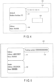
- FIG. 4 illustrates an example of an instruction picture 30 generated with the processor 11. As illustrated in FIG. 4 , the instruction picture 30 displays a display region 31, a display region 32, an input form 33, and a display region 34, and the like.
- the display region 31 displays articles to be picked up and the number of articles to be picked up.
- the display region 31 indicates that 10 articles A are to be picked up.
- the display region 31 may indicate a plurality of types of articles.
- the display region 32 displays information (entry information) entered in the address slip or part of the entry information.
- the display region 32 displays part of the address.
- the display region 32 displays the name of the address.
- the contents displayed in the display region 32 is not limited to any specific structure.
- the input form 33 receives an input of articles that have been picked up with the WES 20.
- the input form 33 receives an input of the number of articles that have been picked up with the WES 20.
- the input form 33 may receive an input of the number by key input. As another example, the input form 33 may receive an input of the number by a tap on an icon.
- the input form 33 may receive an input indicating that pickup has been finished.
- the input form 33 may be formed of input forms corresponding to the respective types of articles.
- the display region 34 displays an ID (first ID) to identify the delivery business of articles.
- the display region 34 displays a first ID to identify the business form.
- the structure of the instruction picture 30 is not limited to any specific structure.
- the processor 11 supplies the generated instruction picture to the distributor 3 via the display interface 16. Specifically, the processor 11 supplies the generated instruction picture to the display unit 4 and the controller 7.
- the processor 11 receives an input to the input form 33.
- the processor 11 has a function of printing the address slip using the printer 2.
- the processor 11 generates image data to print the address slip on the basis of the acquired order list.
- the processor 11 supplies the generated image data to the printer 2 via the printer interface 18.
- FIG. 5 illustrates an example of an address slip 40 printed with the processor 11.
- the address slip 40 includes a display region 41, a display region 42, and a display region 43.
- the display region 41 is a region in which information relating to the address is to be printed. Herein, the display region 41 displays the address and the name of the address.
- the display region 42 is a region in which information relating to the sender is to be printed.
- the display region 41 displays the address and the name of the sender.
- the display region 43 is a region to print a tracking number to track the parcel to which the address slip is attached.
- the processor 11 sets tracking numbers for address slips at random or as serial numbers.
- the address slip 40 may also include a region in which information (such as the name or the number of articles) relating to the articles is to be printed.
- the address slip may include a region in which the delivery company name is to be printed.
- the structure of the address slip 40 is not limited to any specific structure.
- the address slip 40 may have a structure in which the format is printed in advance. For example, in the address slip 40, frames of the display regions 41 to 43 are printed in advance.
- the processor 11 may print information in the frames of the display regions 41 to 43 using the printer 2.
- the functions achieved with the WES 20 are achieved by execution, with the processor 21, of the programs stored in the ROM 22 or the NVM 24 or the like.
- the processor 21 has a function of acquiring the instruction picture 30 via the controller interface 25.
- the processor 11 of the WMS 10 supplies the instruction picture 30 to the controller 7.
- the processor 21 acquires the instruction picture 30 from the controller 7 via the controller interface 25.
- the processor 21 also has the function of acquiring the first ID from the acquired instruction picture 30.
- the processor 21 extracts the region (display region 34 herein) to display the first ID from the instruction picture 30, in accordance with the format or the like of the instruction picture 30.
- the processor 21 executes OCR (Optical Character Recognition) processing for the display region 34.
- the processor 21 acquires the first ID on the basis of the result of the OCR processing.
- the processor 21 also has a function of picking up articles on the basis of the acquired instruction picture 30.
- the processor 21 extracts a region (display region 31 herein) indicating articles to be picked up from the instruction picture 30, in accordance with the format or the like of the instruction picture 30.
- the processor 21 executes OCR processing for the display region 31.
- the processor 21 specifies articles to be picked up and the number of articles to be picked up, on the basis of the result of the OCR processing.
- the processor 21 picks up the articles in accordance with the specified articles and the specified number of articles. Specifically, the processor 21 picks up the specified number of articles using the robot 8.
- the processor 21 may move the shelf storing the articles or the like using an AGV (automatic guided vehicle) or the like.
- the processor 21 inputs an operating signal to input the number of picked articles and the like to the WMS 10 using the controller 7.
- the processor 21 may input an operating signal to input the number of picked articles and the like to the WMS 10 using the controller 7 each time pickup of one type of articles is finished.
- the processor 21 also has a function of scanning an address slip using the scanner 9.
- the processor 21 scans the address slip using the scanner 9.
- the processor 21 acquires an image (address'slip image) acquired by scanning the address slip from the scanner 9.
- the processor 21 also has a function of extracting feature information indicating the feature of the address slip 40 from the address slip image.
- the feature information is formed of geometric information indicating a geometric feature of the address slip 40, and entry information indicating a character string entered in the address slip 40.
- the processor 21 extracts labels (such as the display regions 41 to 43) of the address slip 40 from the address slip image by labeling processing or the like.
- the processor 21 executes OCR processing for each of the labels.
- the processor 21 acquires the address (such as the name and the address), the sender (such as the name and the address), or the tracking number, as the entry information, on the basis of the result of the OCR processing.
- the processor 21 also extracts geometric information from the address slip image in accordance with the predetermined algorithm. For example, as the geometric information, the processor 21 extracts a feature relating to the size of the address slip 40, the size, the position, or the color of each of the labels, or the color or the texture (for example, spatial frequency information) of the part outside the labels of address slip 40.
- the processor 21 may acquire the entry information (or part of the entry information) from the instruction picture 30. For example, the processor 21 extracts the region (display region 32 herein) indicating the entry information from the instruction picture 30, in accordance with the format or the like of the instruction picture 30. When the display region 32 is extracted, the processor 21 executes OCR (Optical Character Recognition) processing for the display region 32.
- OCR Optical Character Recognition
- the processor 21 acquires the entry information (or part of the entry information) on the basis of the result of the OCR processing.
- the processor 21 integrates the geometric information and the entry information to generate feature information.
- the processor 21 also has a function of setting an ID (second ID) to identify the address slip 40 for the address slip 40.
- the processor 21 generates a character string formed of a text, a numerical value, a sign, or a combination thereof as the second ID.
- the processor 21 may generate a random character string as the second ID.
- the processor 21 may generate the second ID as a serial number.
- the processor 21 may generate the second ID on the basis of the entry information of the address slip 40.
- the processor 21 may generate the tracking number indicated with the entry information as the second ID.
- the processor 21 may generate a character string acquired by combining the delivery company name of the address slip 40 with the tracking number as the second ID.
- the processor 21 associates the first ID and the generated second ID with the extracted feature information, and store them in the NVM 24.
- the processor 21 may generate a table storing the first ID, the generated second ID, and the extracted feature information in association with each other.
- the processor 21 also has a function of retrieving the first ID and the second ID from the address slip image.
- the processor 21 acquires the address slip image of the address slip 40 using the scanner 9.
- the processor 21 acquires the address slip image at a step downstream from the step of setting the second ID for the address slip 40.
- the processor 21 acquires the address slip image of the address slip 40 in a conveying path through which the articles to which the address slip 40 is attached are delivered to a predetermined place.
- the processor 21 extracts feature information from the address slip image.
- the method for extracting feature information with the processor 21 is as described above.
- the processor 21 retrieves feature information matching with the extracted feature information from the NVM 24.
- the processor 21 acquires the first ID and the second ID corresponding to the retrieved feature information.
- the processor 21 updates the retrieved feature information on the basis of the extracted feature information. For example, the processor 21 overwrites the geometric information of the retrieved feature information with the geometric information of the extracted feature information.
- the method for updating the retrieved feature information with the processor 21 is not limited to any specific method.
- FIG. 6 is a flowchart for explaining an operation example of the WMS 10.
- the processor 11 of the WMS 10 acquires an order list via the communication unit 15 or the like (S11).
- the processor 11 supplies the instruction picture 30 to the distributor 3 on the basis of the acquired order list or the like via the display interface 16 (S12).
- the processor 11 prints the address slip 40 on the basis of the acquired order list or the like using the printer 2 (S13).
- the processor 11 receives an input, such as the number of picked articles, via the operation interface 17 (S14).
- the processor 11 ends the operation.
- FIG. 7 is a flowchart for explaining an operation example of picking up articles with the WES 20.
- the processor 21 of the WES 20 acquires the instruction picture 30 from the controller 7 via the controller interface 25 (S21).
- the processor 21 executes OCR processing for the display region 31 and the display region 34 of the instruction picture 30 (S22).
- the processor 21 acquires the first ID on the basis of the result of the OCR processing (S23).
- the processor 11 picks up the articles using the robot 8 on the basis of the result of the OCR processing (S24).
- the processor 21 inputs the number of picked articles or the like to the WMS 10 using the controller 7 (S25).
- the processor 21 determines whether pickup of the articles has been finished (S26). If it is determined that pickup of the articles has not been finished (NO at S26), the processor 21 returns to S24.
- the processor 21 ends the operation.
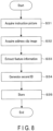
- FIG. 8 is a flowchart for explaining an operation example of setting the second ID for the address slip 40 with the WES 20.
- the processor 21 of the WES 20 acquires the instruction picture 30 from the controller 7 via the controller interface 25 (S31).
- the processor 21 may execute the operation of S31 as the operation of the S21.
- the processor 21 acquires the address slip image of the address slip 40 using the scanner 9 (S32).
- the processor 21 extracts feature information on the basis of the address slip image and the instruction picture 30 (S33).
- the processor 21 When the feature information is extracted, the processor 21 generates a second ID. When the second ID is generated, the processor 21 associates the generated second ID with the extracted feature information, and stores them in the NVM 24 (S35).
- the processor 21 ends the operation.
- the following is an explanation of an operation example of retrieving the first ID and the second ID with the WES 20.
- FIG. 9 is a flowchart for explaining an operation example of retrieving the first ID and the second ID with the WES 20.
- the processor 21 of the WES 20 acquires an address slip image of the address slip 40 using the scanner 9 (S41).
- the processor 21 extracts feature information from the address slip image (S42).
- the processor 21 retrieves feature information matching with the extracted feature information from the NVM 24 (S43).
- the processor 21 acquires the first ID and the second ID corresponding to the retrieved feature information (S44).
- the processor 21 updates the retrieved feature information on the basis of the extracted feature information (S45).
- the processor 21 ends the operation.
- the processor 11 of the WMS 10 may execute S12 after S13. As another example, the processor 11 may execute S12 and S13 simultaneously.
- the instruction picture 30 may include no entry information (or part of entry information). Specifically, the instruction picture 30 may include no display region 32. In this case, the processor 21 of the WES 20 is not required to acquire the entry information from the instruction picture 30.
- the processor 21 is not required to update the retrieved feature information.
- the processor 21 may retrieve the first ID or the second ID.
- the WES structured as described above scans an address slip.
- the WES extracts feature information indicating the feature of the address slip from the image or the like of the address slip.
- the WES associates the first ID to identify the delivery business and the second ID to identify the address slip with the extracted feature information, and stores them.
- the WES scans the address slip and extracts the feature information of the address slip at a step downstream from the step of setting the second ID.
- the WES retrieves feature information matching with the extracted feature information.
- the WES acquires the first ID and the second ID corresponding to the retrieved feature information.
- the WES is enabled to manage address slips without attaching bar codes or the like to the address slips.
Landscapes
- Engineering & Computer Science (AREA)
- Physics & Mathematics (AREA)
- Computer Vision & Pattern Recognition (AREA)
- General Physics & Mathematics (AREA)
- Theoretical Computer Science (AREA)
- Multimedia (AREA)
- Business, Economics & Management (AREA)
- Economics (AREA)
- Artificial Intelligence (AREA)
- Geometry (AREA)
- Computer Graphics (AREA)
- Marketing (AREA)
- Development Economics (AREA)
- Entrepreneurship & Innovation (AREA)
- Human Resources & Organizations (AREA)
- Mechanical Engineering (AREA)
- Operations Research (AREA)
- Quality & Reliability (AREA)
- Strategic Management (AREA)
- Tourism & Hospitality (AREA)
- General Business, Economics & Management (AREA)
- Management, Administration, Business Operations System, And Electronic Commerce (AREA)
- Character Input (AREA)
Abstract
Description
- Embodiments described herein relate generally to an information processing apparatus and a system.
- A physical distribution system has been provided. The physical distribution system picks up articles in accordance with an order list or the like, and attaches address slips to the picked articles. Such a physical distribution system indicates articles to be picked up for the operator on the screen. The physical distribution system also prints the address slips.
- In addition, an apparatus to automate pickup has been provided. The apparatus acquires a picture from the physical distribution system and picks up articles with a robot.
- In such an apparatus, a technique is required to properly managing address slips without newly attaching bar codes or the like to the address slips.
- Patent Literature 1: PCT International Publication No. 2020/100956
- To solve the problem described above, an information processing apparatus and a system capable of effectively managing slips are provided.
- According to an embodiment, an information processing apparatus includes a first interface, a storage unit, and a processor. The first interface acquires an instruction picture indicating an article to be picked up. The storage unit stores data. The processor acquires a first ID from the instruction picture, generates feature information indicating a feature of a slip to deliver the article, generates a second ID, associates the first ID and the second ID with the feature information, and stores them in the storage unit.
-
-
FIG. 1 is a block diagram illustrating a configuration example of a physical distribution system according to an embodiment. -
FIG. 2 is a block diagram illustrating a configuration example of a WMS according to the embodiment. -
FIG. 3 is a block diagram illustrating a configuration example of a WES according to the embodiment. -
FIG. 4 is a diagram illustrating an example of an instruction picture according to the embodiment. -
FIG. 5 is a diagram illustrating an example of an address slip according to the embodiment. -
FIG. 6 is a flowchart illustrating an operation example of the WMS according to the embodiment. -
FIG. 7 is a flowchart illustrating an operation example of the WES according to the embodiment. -
FIG. 8 is a flowchart illustrating an operation example of the WES according to the embodiment. -
FIG. 9 is a flowchart illustrating an operation example of the WES according to the embodiment. - An embodiment will be explained hereinafter with reference to drawings.
- A physical distribution system according to one embodiment picks up articles from shelves or the like in a warehouse. The physical distribution system prints address slips to deliver the picked articles. The physical distribution system attaches address slips to the picked articles or vessels packing the articles. The physical distribution system supplies the articles or vessels provided with the slips to a delivery system or the like.
- For example, the physical distribution system is used as a system of e-commerce.
-
FIG. 1 illustrates a configuration example of aphysical distribution system 1. As illustrated inFIG. 1 , thephysical distribution system 1 includes aprinter 2, adistributor 3, adisplay unit 4, aselector 5, anoperating unit 6, a controller 7, arobot 8, ascanner 9, a WMS 10, and aWES 20, and the like. - The WMS 10 is connected to the
printer 2, thedistributor 3, and theselector 5. Thedistributor 3 is connected to thedisplay unit 4 and the controller 7. Theselector 5 is connected to theoperating unit 6 and the controller 7. The WES 20 is connected to the controller 7, therobot 8, and thescanner 9. - The
physical distribution system 1 may further include any other necessary structures in addition to the structure illustrated inFIG. 1 , or any specific structure may be excluded from thephysical distribution system 1. - The WMS 10 (Warehouse Management System) (first information processing apparatus) manages the whole
physical distribution system 1. The WMS 10 acquires an order list from an external apparatus or the like. The order list indicates articles to be picked up and an address to which the articles are to be delivered. The WMS 10 supplies thedistributor 3 with an instruction picture indicating articles to be picked up in accordance with the order list. The WMS 10 also receives an input, such as the number of articles having been picked up, through theselector 5. The WMS 10 also prints an address slip. The WMS 10 will be described in detail below. - The WES 20 (Warehouse Management System) (information processing apparatus, second information processing apparatus) picks up articles in accordance with the instruction picture or the like. The WES 20 also sets an ID for the address slip from the
WMS 10. The WES 20 will be described in detail below. - The
printer 2 prints an image in accordance with control from theWMS 10. Herein, theprinter 2 prints an address slip. For example, theprinter 2 supplies an address slip in accordance with a predetermined format. Theprinter 2 prints the address and the sender and the like on the supplied address slip. - For example, the
printer 2 forms an image by an inkjet method or an electrophotographic method. When address slips are formed of heat sensitive paper, theprinter 2 may form an image by heating the address slip. The structure of theprinter 2 is not limited to any specific structure. - The
distributor 3 distributes a picture from theWMS 10 to thedisplay unit 4 and the controller 7. Specifically, thedistributor 3 acquires a signal to display a picture from theWMS 10, and supplies the signal to thedisplay unit 4 and the controller 7. Thedistributor 3 may amplify or modulate the signal. - The
display unit 4 displays the picture from thedistributor 3. Specifically, thedisplay unit 4 displays a picture (for example, an instruction picture) supplied from theWMS 10. For example, thedisplay unit 4 is a liquid crystal monitor or the like. - The
selector 5 supplies an operating signal from theoperating unit 6 or the controller 7 to theWMS 10. Specifically, theselector 5 supplies theWMS 10 with an operating signal indicating an operation input by the operator to theoperating unit 6 or an operating signal generated with the controller 7. - The
operating unit 6 receives an input of various operations from the operator. Theoperating unit 6 transmits an operating signal indicating an input operation to theselector 5. Theoperating unit 6 is formed of a keyboard or a mouse. - The controller 7 has a function of a capture board capturing a picture (that is, picture from WMS 10) from the
distributor 3, and a function of an emulator generating an operating signal to be supplied to the selector 5 (that is, to WMS 10). - The controller 7 acquires a picture from the
distributor 3, as the function of a capture board. The controller 7 supplies the acquired display image to theWES 20. - The controller 7 also emulates an operating terminal, such as the keyboard or the mouse connected to the
WMS 10, as the function of an emulator. The controller 7 supplies theWMS 10 with an operating signal similar to the operating signal input by the operator through the operating terminal, in accordance with control from theWES 20. For example, the controller 7 supplies theWMS 10 with an operating signal indicating movement or click of the mouse or a keyboard input. - The
robot 8 picks up an article in accordance with control from theWES 20. Therobot 8 puts the picked article into a predetermined place (such as a predetermined vessel). - For example, the
robot 8 is formed of a robot arm and a robot hand attached to a distal end of the robot arm and the like. Therobot 8 moves the robot hand using the robot arm to a position in which the robot hand can pick up the article. Therobot 8 traps the article with the robot hand. Therobot 8 moves the trapped article using the robot arm to a predetermined position. Therobot 8 opens the robot hand to put the article into the predetermined position. - The
robot 8 may include a structure to change robot hands according to articles. The structure of therobot 8 is not limited to any specific structure. - The
scanner 9 scans an address slip printed with theWMS 10. Thescanner 9 supplies image data acquired by scanning to theWES 20. - For example, the
scanner 9 is set adjacent to theprinter 2. Thescanner 9 images an address slip ejected from theprinter 2. In this case, thescanner 9 is formed of a camera or the like. - As another example, the
scanner 9 may scan an address slip attached to an article. For example, thescanner 9 is set on a conveying path for articles. In this case, thescanner 9 may be formed of a line of sensors arranged in a horizontal scanning direction. - As another example, the
scanner 9 may be formed of a plurality of scanners. For example, thescanner 9 may be formed of a scanner set adjacent to theprinter 2 and a scanner set on a conveying path for articles provided with address slips. - The following is an explanation of the
WMS 10. -
FIG. 2 illustrates a configuration example of theWMS 10 according to the embodiment.FIG. 2 is a block diagram illustrating a configuration example of theWMS 10. As illustrated inFIG. 2 , theWMS 10 includes aprocessor 11, aROM 12, aRAM 13, aNVM 14, acommunication unit 15, adisplay interface 16, anoperation interface 17, and aprinter interface 18 and the like. - The
processor 11, theROM 12, theRAM 13, theNVM 14, thecommunication unit 15, thedisplay interface 16, theoperation interface 17, and theprinter interface 18 are connected to each other via a data bus or the like. - The
WMS 10 may include any other necessary structures in addition to the structure illustrated inFIG. 2 , or any specific structure may be excluded from theWMS 10. - The processor 11 (first processor) has a function of controlling operations of the
whole WMS 10. Theprocessor 11 may include an internal cashe and various interfaces and the like. Theprocessor 11 achieves various types of processing by executing programs stored in advance in the internal memory, theROM 12, or theNVM 14. - Part of the various functions achieved by execution of the programs with the
processor 11 may be achieved with a hardware circuit. In this case, theprocessor 11 controls the function executed with the hardware circuit. - The
ROM 12 is a non-volatile memory storing a control program and control data and the like in advance. The control program and the control data stored in theROM 12 are installed in advance in accordance with specifications of theWMS 10. - The
RAM 13 is a volatile memory. TheRAM 13 temporarily stores data being processed with theprocessor 11 or the like. TheRAM 13 stores various application programs on the basis of commands from theprocessor 11. TheRAM 13 may also store data necessary for execution of the application programs and execution results of the application programs. - The
NVM 14 is a non-volatile memory for which writing and rewriting of data are possible. For example, theNVM 14 is formed of a HDD, a SSD, or a flash memory or the like. TheNVM 14 stores a control program, applications, and various types of data according to operation use of theWMS 10. - The
communication unit 15 is an interface to transmit and receive data to and from an external apparatus. For example, thecommunication unit 15 is an interface supporting wired or wireless LAN (Local Area Network) connection. - The
display interface 16 is an interface to transmit and receive data to and from thedistributor 3. Thedisplay interface 16 transmits a signal to display a picture to thedistributor 3 in accordance with control from theprocessor 11. - The
operation interface 17 is an interface to transmit and receive data to and from an input device receiving an input of operation. For example, theoperation interface 17 receives an operating signal indicating an operation input to an operating terminal, such as a keyboard and a mouse. Theoperation interface 17 supplies the received operating signal to theprocessor 11. For example, theoperation interface 17 supports USB (Universal Serial Bus) connection. - Herein, the
operation interface 17 is connected to theselector 5. Specifically, theoperation interface 17 receives an operating signal from theselector 5. - The
printer interface 18 is an interface to transmit and receive data to and from theprinter 2. Theprinter interface 18 supplies image data to be printed to theprinter 2 in accordance with control from theprocessor 11. Theprinter interface 18 may supply a setting signal and the like to theprinter 2 in accordance with control from theprocessor 11. - For example, the
WMS 10 is a desktop PC or a notebook PC. - The following is an explanation of the
WES 20. -
FIG. 3 illustrates a configuration example of theWES 20 according to the embodiment.FIG. 3 is a block diagram illustrating a configuration example of theWES 20. As illustrated inFIG. 3 , theWES 20 includes aprocessor 21, aROM 22, aRAM 23, aNVM 24, acontroller interface 25, arobot interface 26, ascanner interface 27, adisplay unit 28, and anoperating unit 29, and the like. - The
processor 21, theROM 22, theRAM 23, theNVM 24, thecontroller interface 25, therobot interface 26, thescanner interface 27, thedisplay unit 28, and the operatingunit 29 are connected to each other via a data bus or the like. - The
WES 20 may further include any other necessary structures in addition to the structure illustrated inFIG. 3 , or any specific structure may be excluded from theWES 20. - The processor 21 (second processor) has a function of controlling operations of the
whole WES 20. Theprocessor 21 may include an internal cashe and various interfaces and the like. Theprocessor 21 achieves various types of processing by executing programs stored in advance in the internal memory, theROM 22, or theNVM 24. - Part of the various functions achieved by execution of the programs with the
processor 21 may be achieved with a hardware circuit. In this case, theprocessor 21 controls the function executed with the hardware circuit. - The
ROM 22 is a non-volatile memory storing a control program and control data and the like in advance. The control program and the control data stored in theROM 22 are installed in advance in accordance with specifications of theWES 20. - The
RAM 23 is a volatile memory. TheRAM 23 temporarily stores data being processed with theprocessor 21 or the like. TheRAM 23 stores various application programs on the basis of commands from theprocessor 21. TheRAM 23 may also store data necessary for execution of the application programs and execution results of the application programs. - The NVM 24 (storage unit) is a non-volatile memory for which writing and rewriting of data are possible. For example, the
NVM 24 is formed of a HDD, a SSD, or a flash memory or the like. TheNVM 24 stores a control program, applications, and various types of data according to operation use of theWES 20. - The
controller interface 25 is an interface to transmit and receive data to and from the controller 7. - The controller interface 25 (first interface) acquires a picture from the controller 7. The
controller interface 25 supplies the acquired picture to theprocessor 21. - The
controller interface 25 causes the controller 7 to output an operating signal to theselector 5 in accordance with control from theprocessor 21. For example, thecontroller interface 25 supports USB connection. - The
robot interface 26 is an interface to transmit and receive data to and from therobot 8. Therobot interface 26 causes therobot 8 to pick up articles in accordance with control from theprocessor 21. Therobot interface 26 may acquire the picked articles and the number of picked articles from therobot 8. Therobot interface 26 supplies theprocessor 21 with the picked articles and the number of picked articles. - The scanner interface 27 (second interface) is an interface to transmit and receive data to and from the
scanner 9. Thescanner interface 27 causes thescanner 9 to execute scan in accordance with control from theprocessor 21. Thescanner interface 27 also acquires image data acquired by the scan from thescanner 9. Thescanner interface 27 supplies the acquired image data to theprocessor 21. - The
display unit 28 displays various types of information by control of theprocessor 21. Thedisplay unit 28 is formed of a liquid crystal monitor. If the operatingunit 29 is formed of a touch panel or the like, thedisplay unit 28 may be formed as one unitary piece with the operatingunit 29. - The operating
unit 29 receives inputs of various operations from the operator. The operatingunit 29 transmits a signal indicating the received operation to theprocessor 21. For example, the operatingunit 29 is formed of a keyboard, a ten-key pad, and a touch panel. - For example, the
WES 20 is a desktop PC or a notebook PC. - The following is an explanation of functions achieved with the
WMS 10. The functions achieved with theWMS 10 are achieved by execution, with theprocessor 11, of the programs stored in theROM 12 or theNVM 14 or the like. - First, the
processor 11 has a function of supplying an instruction picture indicating articles to be picked up via thedisplay interface 16. - The
processor 11 acquires an order list from the external apparatus via thecommunication unit 15 or the like. For example, the order list indicates articles to be picked up, the number of articles to be picked up, and an address of the articles. - When the
processor 11 acquires an order list, theprocessor 11 generates an instruction picture in accordance with the acquired order list. Herein, the instruction picture displays information relating to a business form to be packed together with the articles. -
FIG. 4 illustrates an example of aninstruction picture 30 generated with theprocessor 11. As illustrated inFIG. 4 , theinstruction picture 30 displays adisplay region 31, adisplay region 32, aninput form 33, and adisplay region 34, and the like. - The
display region 31 displays articles to be picked up and the number of articles to be picked up. In this example, thedisplay region 31 indicates that 10 articles A are to be picked up. Thedisplay region 31 may indicate a plurality of types of articles. - The
display region 32 displays information (entry information) entered in the address slip or part of the entry information. Herein, thedisplay region 32 displays part of the address. As illustrated inFIG. 4 , thedisplay region 32 displays the name of the address. The contents displayed in thedisplay region 32 is not limited to any specific structure. - The
input form 33 receives an input of articles that have been picked up with theWES 20. For example, theinput form 33 receives an input of the number of articles that have been picked up with theWES 20. - The
input form 33 may receive an input of the number by key input. As another example, theinput form 33 may receive an input of the number by a tap on an icon. - As another example, the
input form 33 may receive an input indicating that pickup has been finished. - If a plurality of types of articles are to be picked up, the
input form 33 may be formed of input forms corresponding to the respective types of articles. - The
display region 34 displays an ID (first ID) to identify the delivery business of articles. For example, thedisplay region 34 displays a first ID to identify the business form. - The structure of the
instruction picture 30 is not limited to any specific structure. - When the
instruction picture 30 is generated, theprocessor 11 supplies the generated instruction picture to thedistributor 3 via thedisplay interface 16. Specifically, theprocessor 11 supplies the generated instruction picture to thedisplay unit 4 and the controller 7. - When the
instruction picture 30 is supplied, theprocessor 11 receives an input to theinput form 33. - In addition, the
processor 11 has a function of printing the address slip using theprinter 2. Theprocessor 11 generates image data to print the address slip on the basis of the acquired order list. When the image data is generated, theprocessor 11 supplies the generated image data to theprinter 2 via theprinter interface 18. -
FIG. 5 illustrates an example of anaddress slip 40 printed with theprocessor 11. As illustrated inFIG. 5 , theaddress slip 40 includes adisplay region 41, adisplay region 42, and adisplay region 43. - The
display region 41 is a region in which information relating to the address is to be printed. Herein, thedisplay region 41 displays the address and the name of the address. - The
display region 42 is a region in which information relating to the sender is to be printed. Herein, thedisplay region 41 displays the address and the name of the sender. - The
display region 43 is a region to print a tracking number to track the parcel to which the address slip is attached. For example, theprocessor 11 sets tracking numbers for address slips at random or as serial numbers. - The
address slip 40 may also include a region in which information (such as the name or the number of articles) relating to the articles is to be printed. The address slip may include a region in which the delivery company name is to be printed. The structure of theaddress slip 40 is not limited to any specific structure. - The
address slip 40 may have a structure in which the format is printed in advance. For example, in theaddress slip 40, frames of thedisplay regions 41 to 43 are printed in advance. Theprocessor 11 may print information in the frames of thedisplay regions 41 to 43 using theprinter 2. - The following is an explanation of functions achieved with the
WES 20. The functions achieved with theWES 20 are achieved by execution, with theprocessor 21, of the programs stored in theROM 22 or theNVM 24 or the like. - First, the
processor 21 has a function of acquiring theinstruction picture 30 via thecontroller interface 25. - As described above, the
processor 11 of theWMS 10 supplies theinstruction picture 30 to the controller 7. - The
processor 21 acquires theinstruction picture 30 from the controller 7 via thecontroller interface 25. - The
processor 21 also has the function of acquiring the first ID from the acquiredinstruction picture 30. - When the
instruction picture 30 is acquired, theprocessor 21 extracts the region (display region 34 herein) to display the first ID from theinstruction picture 30, in accordance with the format or the like of theinstruction picture 30. When thedisplay region 34 is extracted, theprocessor 21 executes OCR (Optical Character Recognition) processing for thedisplay region 34. - When OCR processing is executed, the
processor 21 acquires the first ID on the basis of the result of the OCR processing. - The
processor 21 also has a function of picking up articles on the basis of the acquiredinstruction picture 30. - The
processor 21 extracts a region (display region 31 herein) indicating articles to be picked up from theinstruction picture 30, in accordance with the format or the like of theinstruction picture 30. When thedisplay region 31 is extracted, theprocessor 21 executes OCR processing for thedisplay region 31. - When OCR processing is executed, the
processor 21 specifies articles to be picked up and the number of articles to be picked up, on the basis of the result of the OCR processing. - When the articles to be picked up and the number of articles to be picked up are specified, the
processor 21 picks up the articles in accordance with the specified articles and the specified number of articles. Specifically, theprocessor 21 picks up the specified number of articles using therobot 8. Theprocessor 21 may move the shelf storing the articles or the like using an AGV (automatic guided vehicle) or the like. - When the pickup is finished, the
processor 21 inputs an operating signal to input the number of picked articles and the like to theWMS 10 using the controller 7. - If a plurality of types of articles are to be picked up, the
processor 21 may input an operating signal to input the number of picked articles and the like to theWMS 10 using the controller 7 each time pickup of one type of articles is finished. - The
processor 21 also has a function of scanning an address slip using thescanner 9. - When the
processor 11 of theWMS 10 prints an address slip using theprinter 2, theprocessor 21 scans the address slip using thescanner 9. Theprocessor 21 acquires an image (address'slip image) acquired by scanning the address slip from thescanner 9. - The
processor 21 also has a function of extracting feature information indicating the feature of theaddress slip 40 from the address slip image. - The feature information is formed of geometric information indicating a geometric feature of the
address slip 40, and entry information indicating a character string entered in theaddress slip 40. - The
processor 21 extracts labels (such as thedisplay regions 41 to 43) of theaddress slip 40 from the address slip image by labeling processing or the like. - When the labels are extracted, the
processor 21 executes OCR processing for each of the labels. When the OCR processing is executed, theprocessor 21 acquires the address (such as the name and the address), the sender (such as the name and the address), or the tracking number, as the entry information, on the basis of the result of the OCR processing. - The
processor 21 also extracts geometric information from the address slip image in accordance with the predetermined algorithm. For example, as the geometric information, theprocessor 21 extracts a feature relating to the size of theaddress slip 40, the size, the position, or the color of each of the labels, or the color or the texture (for example, spatial frequency information) of the part outside the labels ofaddress slip 40. - The
processor 21 may acquire the entry information (or part of the entry information) from theinstruction picture 30. For example, theprocessor 21 extracts the region (display region 32 herein) indicating the entry information from theinstruction picture 30, in accordance with the format or the like of theinstruction picture 30. When thedisplay region 32 is extracted, theprocessor 21 executes OCR (Optical Character Recognition) processing for thedisplay region 32. - When the OCR processing is executed, the
processor 21 acquires the entry information (or part of the entry information) on the basis of the result of the OCR processing. - The
processor 21 integrates the geometric information and the entry information to generate feature information. - The
processor 21 also has a function of setting an ID (second ID) to identify theaddress slip 40 for theaddress slip 40. - The
processor 21 generates a character string formed of a text, a numerical value, a sign, or a combination thereof as the second ID. - The
processor 21 may generate a random character string as the second ID. Theprocessor 21 may generate the second ID as a serial number. - As another example, the
processor 21 may generate the second ID on the basis of the entry information of theaddress slip 40. For example, theprocessor 21 may generate the tracking number indicated with the entry information as the second ID. As another example, theprocessor 21 may generate a character string acquired by combining the delivery company name of theaddress slip 40 with the tracking number as the second ID. - When the second ID is generated, the
processor 21 associates the first ID and the generated second ID with the extracted feature information, and store them in theNVM 24. Theprocessor 21 may generate a table storing the first ID, the generated second ID, and the extracted feature information in association with each other. - The
processor 21 also has a function of retrieving the first ID and the second ID from the address slip image. - The
processor 21 acquires the address slip image of theaddress slip 40 using thescanner 9. Herein, theprocessor 21 acquires the address slip image at a step downstream from the step of setting the second ID for theaddress slip 40. For example, theprocessor 21 acquires the address slip image of theaddress slip 40 in a conveying path through which the articles to which theaddress slip 40 is attached are delivered to a predetermined place. - When the address slip image is acquired, the
processor 21 extracts feature information from the address slip image. The method for extracting feature information with theprocessor 21 is as described above. - When the feature information is extracted, the
processor 21 retrieves feature information matching with the extracted feature information from theNVM 24. When feature information matching with the extracted feature information is retrieved, theprocessor 21 acquires the first ID and the second ID corresponding to the retrieved feature information. - When the first ID and the second ID corresponding to the retrieved feature information are acquired, the
processor 21 updates the retrieved feature information on the basis of the extracted feature information. For example, theprocessor 21 overwrites the geometric information of the retrieved feature information with the geometric information of the extracted feature information. The method for updating the retrieved feature information with theprocessor 21 is not limited to any specific method. - The following is an explanation of an operation example of the
WMS 10. -
FIG. 6 is a flowchart for explaining an operation example of theWMS 10. - First, the
processor 11 of theWMS 10 acquires an order list via thecommunication unit 15 or the like (S11). When the order list is acquired, theprocessor 11 supplies theinstruction picture 30 to thedistributor 3 on the basis of the acquired order list or the like via the display interface 16 (S12). - When the
instruction picture 30 is supplied to thedistributor 3, theprocessor 11 prints theaddress slip 40 on the basis of the acquired order list or the like using the printer 2 (S13). When the address slip is printed, theprocessor 11 receives an input, such as the number of picked articles, via the operation interface 17 (S14). - When an input, such as the number of picked articles, is received, the
processor 11 ends the operation. - The following is an explanation of an operation example of the
WES 20. - First, an operation example of picking up articles with the
WES 20 will be explained hereinafter. -
FIG. 7 is a flowchart for explaining an operation example of picking up articles with theWES 20. - First, the
processor 21 of theWES 20 acquires theinstruction picture 30 from the controller 7 via the controller interface 25 (S21). When theinstruction picture 30 is acquired, theprocessor 21 executes OCR processing for thedisplay region 31 and thedisplay region 34 of the instruction picture 30 (S22). - When the OCR processing is executed, the
processor 21 acquires the first ID on the basis of the result of the OCR processing (S23). When the first ID is acquired, theprocessor 11 picks up the articles using therobot 8 on the basis of the result of the OCR processing (S24). When the articles are picked up, theprocessor 21 inputs the number of picked articles or the like to theWMS 10 using the controller 7 (S25). - When the number of picked articles or the like is input to the
WMS 10, theprocessor 21 determines whether pickup of the articles has been finished (S26). If it is determined that pickup of the articles has not been finished (NO at S26), theprocessor 21 returns to S24. - If it is determined that pickup of the articles has been finished (YES at S26), the
processor 21 ends the operation. - The following is an explanation of an operation example of setting the second ID for the
address slip 40 with theWES 20. -
FIG. 8 is a flowchart for explaining an operation example of setting the second ID for theaddress slip 40 with theWES 20. - First, the
processor 21 of theWES 20 acquires theinstruction picture 30 from the controller 7 via the controller interface 25 (S31). Theprocessor 21 may execute the operation of S31 as the operation of the S21. - When the
instruction picture 30 is acquired, theprocessor 21 acquires the address slip image of theaddress slip 40 using the scanner 9 (S32). When the address slip image is acquired, theprocessor 21 extracts feature information on the basis of the address slip image and the instruction picture 30 (S33). - When the feature information is extracted, the
processor 21 generates a second ID. When the second ID is generated, theprocessor 21 associates the generated second ID with the extracted feature information, and stores them in the NVM 24 (S35). - When the first ID, the generated second ID, and the extracted feature information are associated with each other and stored in the
NVM 24, theprocessor 21 ends the operation. - The following is an explanation of an operation example of retrieving the first ID and the second ID with the
WES 20. -
FIG. 9 is a flowchart for explaining an operation example of retrieving the first ID and the second ID with theWES 20. - First, the
processor 21 of theWES 20 acquires an address slip image of theaddress slip 40 using the scanner 9 (S41). When the address slip image is acquired, theprocessor 21 extracts feature information from the address slip image (S42). - When the feature information is extracted, the
processor 21 retrieves feature information matching with the extracted feature information from the NVM 24 (S43). When feature information matching with the extracted feature information is retrieved, theprocessor 21 acquires the first ID and the second ID corresponding to the retrieved feature information (S44). - When the first ID and the second ID corresponding to the retrieved feature information are acquired, the
processor 21 updates the retrieved feature information on the basis of the extracted feature information (S45). When the retrieved feature information is updated, theprocessor 21 ends the operation. - The
processor 11 of theWMS 10 may execute S12 after S13. As another example, theprocessor 11 may execute S12 and S13 simultaneously. - In addition, the
instruction picture 30 may include no entry information (or part of entry information). Specifically, theinstruction picture 30 may include nodisplay region 32. In this case, theprocessor 21 of theWES 20 is not required to acquire the entry information from theinstruction picture 30. - As another example, the
processor 21 is not required to update the retrieved feature information. - As another example, the
processor 21 may retrieve the first ID or the second ID. - The WES structured as described above scans an address slip. The WES extracts feature information indicating the feature of the address slip from the image or the like of the address slip. The WES associates the first ID to identify the delivery business and the second ID to identify the address slip with the extracted feature information, and stores them.
- In addition, the WES scans the address slip and extracts the feature information of the address slip at a step downstream from the step of setting the second ID. The WES retrieves feature information matching with the extracted feature information. The WES acquires the first ID and the second ID corresponding to the retrieved feature information.
- As a result, the WES is enabled to manage address slips without attaching bar codes or the like to the address slips.
- Embodiments of the present invention described above are presented as examples, and are not intended to limit the scope of the invention. These novel embodiments can be carried out in other various forms, and various omissions, replacement, and changes are possible within a range not departing from the gist of the invention. These embodiments and modifications thereof are included in the scope and the gist of the invention, and included in the inventions described in the claims and equivalents thereof.
Claims (8)
- An information processing apparatus comprising:a first interface acquiring an instruction picture indicating an article to be picked up in a warehouse;a second interface connected to a scanner scanning a slip to deliver the article;a processor acquiring a first ID from the instruction picture acquired via the first interface, generating feature information indicating a feature of the slip and a second ID from an image of the slip acquired via the second interface, and associating the first ID and the second ID with the feature information; anda storage unit storing the first ID, the second ID, and the feature information associated by the processor.
- The information processing apparatus according to claim 1, whereinthe processor extracts entry information entered in the slip from the image of the slip by OCR processing, andthe feature information includes the entry information.
- The information processing apparatus according to claim 1 or 2, wherein the feature information includes geometric information indicating a geometric feature of the slip.
- The information processing apparatus according to claim 2, wherein the entry information includes an address.
- The information processing apparatus according to claim 2 or 4, wherein the processor generates the second ID based on the entry information.
- The information processing apparatus according to claim 1, wherein the processor acquires a second image of the slip using the scanner after associating the first ID and the second ID with the feature information, extracts the feature information from the second image, retrieves feature information matching with the feature information extracted from the second image from the storage unit, and acquires the first ID or the second ID corresponding to the retrieved feature information.
- The information processing apparatus according to claim 6, wherein the processor updates the retrieved feature information, based on the feature information extracted from the second image.
- A system formed of a first information processing apparatus and a second information processing apparatus,the first information processing apparatus including:a display interface outputting an image;a printer interface connected to a printer; anda first processor outputting an instruction picture indicating an article to be picked up via the display interface, and printing a slip to deliver the article using the printer,the second information processing apparatus including:a first interface acquiring the instruction picture;a second interface connected to a scanner scanning the slip;a second processor acquiring a first ID from the instruction picture acquired via the firstinterface, generating feature information indicating a feature of the slip and a second ID from an image of the slip acquired via the second interface, and associating the first ID and the second ID with the feature information; anda storage unit storing the first ID, the second ID, and the feature information associated by the second processor.
Applications Claiming Priority (2)
| Application Number | Priority Date | Filing Date | Title |
|---|---|---|---|
| JP2020158757A JP6877618B1 (en) | 2020-09-23 | 2020-09-23 | Information processing equipment and systems |
| PCT/JP2021/034713 WO2022065343A1 (en) | 2020-09-23 | 2021-09-22 | Information processing device and system |
Publications (2)
| Publication Number | Publication Date |
|---|---|
| EP4219348A1 true EP4219348A1 (en) | 2023-08-02 |
| EP4219348A4 EP4219348A4 (en) | 2024-10-23 |
Family
ID=75961519
Family Applications (1)
| Application Number | Title | Priority Date | Filing Date |
|---|---|---|---|
| EP21872472.2A Pending EP4219348A4 (en) | 2020-09-23 | 2021-09-22 | INFORMATION PROCESSING DEVICE AND SYSTEM |
Country Status (5)
| Country | Link |
|---|---|
| US (1) | US20230196814A1 (en) |
| EP (1) | EP4219348A4 (en) |
| JP (1) | JP6877618B1 (en) |
| CN (1) | CN115997226A (en) |
| WO (1) | WO2022065343A1 (en) |
Families Citing this family (1)
| Publication number | Priority date | Publication date | Assignee | Title |
|---|---|---|---|---|
| JP2023180072A (en) * | 2022-06-08 | 2023-12-20 | 株式会社東芝 | Information processing equipment, information processing methods, programs and systems |
Family Cites Families (14)
| Publication number | Priority date | Publication date | Assignee | Title |
|---|---|---|---|---|
| JP3333368B2 (en) * | 1995-12-07 | 2002-10-15 | 株式会社日立製作所 | Postal system using communication network |
| JP4407811B2 (en) * | 2003-06-20 | 2010-02-03 | オムロン株式会社 | Work support device |
| JP5924080B2 (en) * | 2012-03-30 | 2016-05-25 | 株式会社寺岡精工 | Picking system, portable terminal device |
| US9298997B1 (en) * | 2014-03-19 | 2016-03-29 | Amazon Technologies, Inc. | Signature-guided character recognition |
| CN105761029A (en) * | 2014-12-17 | 2016-07-13 | 阿里巴巴集团控股有限公司 | Express delivery identification information processing method and device |
| JP6218151B2 (en) * | 2015-03-31 | 2017-10-25 | 三菱電機インフォメーションシステムズ株式会社 | Shipping work support method, shipping work support device, and shipping work support program |
| JP6590153B2 (en) * | 2016-03-23 | 2019-10-16 | パナソニックIpマネジメント株式会社 | Projection instruction apparatus, package sorting system, and projection instruction method |
| EP3249593A1 (en) * | 2016-05-25 | 2017-11-29 | Siemens Aktiengesellschaft | Method for processing a postal article and mail description system |
| EP3373232B1 (en) * | 2017-03-09 | 2020-12-09 | Interroll Holding AG | Intralogistic arrangement |
| JP6887838B2 (en) * | 2017-03-21 | 2021-06-16 | 東芝テック株式会社 | Information processing equipment, information collection equipment and information collection system |
| US20200151665A1 (en) * | 2018-11-13 | 2020-05-14 | Lifetime Brands, Inc. | Visual picking for single pick and single pack warehouse management |
| CN113196005A (en) | 2018-11-14 | 2021-07-30 | 日本电气株式会社 | Information processing system, information processing method, and recording medium |
| CN110414897A (en) * | 2019-07-30 | 2019-11-05 | 北京梧桐车联科技有限责任公司 | Goods delivery management method, device, terminal and storage medium |
| CN210639644U (en) * | 2019-08-16 | 2020-05-29 | 苏州市厚宏智能科技有限公司 | Warehouse management device and system |
-
2020
- 2020-09-23 JP JP2020158757A patent/JP6877618B1/en active Active
-
2021
- 2021-09-22 WO PCT/JP2021/034713 patent/WO2022065343A1/en not_active Ceased
- 2021-09-22 EP EP21872472.2A patent/EP4219348A4/en active Pending
- 2021-09-22 CN CN202180053361.0A patent/CN115997226A/en active Pending
-
2023
- 2023-02-21 US US18/171,840 patent/US20230196814A1/en not_active Abandoned
Also Published As
| Publication number | Publication date |
|---|---|
| EP4219348A4 (en) | 2024-10-23 |
| CN115997226A (en) | 2023-04-21 |
| JP6877618B1 (en) | 2021-05-26 |
| WO2022065343A1 (en) | 2022-03-31 |
| JP2022052387A (en) | 2022-04-04 |
| US20230196814A1 (en) | 2023-06-22 |
Similar Documents
| Publication | Publication Date | Title |
|---|---|---|
| US20080130044A1 (en) | Communication System | |
| US10469796B2 (en) | Information processing apparatus, information processing method, and non-transitory computer readable storage medium | |
| US20230196814A1 (en) | Information processing apparatus and system | |
| EP3525081B1 (en) | Information processing device, printer, program, and information processing method | |
| US11445084B2 (en) | Work process managing system to manage progress of a job including multiple work processes, work process managing method, and work process managing apparatus | |
| WO2015029406A1 (en) | Transmission system, transmission device, and data transmission method | |
| US9807258B1 (en) | Print data processing method of mobile device and the mobile device | |
| JP7458465B2 (en) | Control device | |
| US7826073B2 (en) | Method of managing settings of properties of an image forming device | |
| JP2009294792A (en) | Information processing apparatus, its control method, information processing system, and control program | |
| EP3432134B1 (en) | Printer and method of controlling printer | |
| JP7052586B2 (en) | Printed matter ordering system, user terminal, server, printed matter ordering method, and program | |
| JP2013105266A (en) | Image processing device, image processing system and program | |
| US20230090804A1 (en) | Image forming device, control method thereof, and image forming system | |
| JP7335524B2 (en) | System, its control method, and program | |
| US11769024B2 (en) | Label issuing method for logistics management using multiple code symbols | |
| JP2009271139A (en) | Image forming apparatus, control method for the same, program and recording medium | |
| EP4216178A1 (en) | Method and system for data matching | |
| EP4667229A1 (en) | Image processing apparatus and information processing method | |
| JP2022077135A (en) | Server device and control program therefor | |
| JP7844946B2 (en) | Information processing device, information processing method, and program | |
| JP2021043833A (en) | Information processing apparatus | |
| JP6191384B2 (en) | Transmission system, transmission apparatus, and data processing method | |
| JP2002049867A (en) | Rental equipment management system | |
| JP6160436B2 (en) | POS system, host device, and host device control method |
Legal Events
| Date | Code | Title | Description |
|---|---|---|---|
| STAA | Information on the status of an ep patent application or granted ep patent |
Free format text: STATUS: THE INTERNATIONAL PUBLICATION HAS BEEN MADE |
|
| PUAI | Public reference made under article 153(3) epc to a published international application that has entered the european phase |
Free format text: ORIGINAL CODE: 0009012 |
|
| STAA | Information on the status of an ep patent application or granted ep patent |
Free format text: STATUS: REQUEST FOR EXAMINATION WAS MADE |
|
| 17P | Request for examination filed |
Effective date: 20230118 |
|
| AK | Designated contracting states |
Kind code of ref document: A1 Designated state(s): AL AT BE BG CH CY CZ DE DK EE ES FI FR GB GR HR HU IE IS IT LI LT LU LV MC MK MT NL NO PL PT RO RS SE SI SK SM TR |
|
| DAV | Request for validation of the european patent (deleted) | ||
| DAX | Request for extension of the european patent (deleted) | ||
| A4 | Supplementary search report drawn up and despatched |
Effective date: 20240923 |
|
| RIC1 | Information provided on ipc code assigned before grant |
Ipc: G06V 30/10 20220101ALI20240917BHEP Ipc: G06Q 10/08 20230101ALI20240917BHEP Ipc: B65G 1/137 20060101AFI20240917BHEP |
|
| RAP1 | Party data changed (applicant data changed or rights of an application transferred) |
Owner name: KABUSHIKI KAISHA TOSHIBA |