EP4219050A1 - Rotational shaft lock device, processing head, and composite processing machine - Google Patents
Rotational shaft lock device, processing head, and composite processing machine Download PDFInfo
- Publication number
- EP4219050A1 EP4219050A1 EP20967024.9A EP20967024A EP4219050A1 EP 4219050 A1 EP4219050 A1 EP 4219050A1 EP 20967024 A EP20967024 A EP 20967024A EP 4219050 A1 EP4219050 A1 EP 4219050A1
- Authority
- EP
- European Patent Office
- Prior art keywords
- rotary shaft
- coupling
- drive unit
- inner ring
- outer ring
- Prior art date
- Legal status (The legal status is an assumption and is not a legal conclusion. Google has not performed a legal analysis and makes no representation as to the accuracy of the status listed.)
- Granted
Links
Images












Classifications
-
- B—PERFORMING OPERATIONS; TRANSPORTING
- B23—MACHINE TOOLS; METAL-WORKING NOT OTHERWISE PROVIDED FOR
- B23Q—DETAILS, COMPONENTS, OR ACCESSORIES FOR MACHINE TOOLS, e.g. ARRANGEMENTS FOR COPYING OR CONTROLLING; MACHINE TOOLS IN GENERAL CHARACTERISED BY THE CONSTRUCTION OF PARTICULAR DETAILS OR COMPONENTS; COMBINATIONS OR ASSOCIATIONS OF METAL-WORKING MACHINES, NOT DIRECTED TO A PARTICULAR RESULT
- B23Q1/00—Members which are comprised in the general build-up of a form of machine, particularly relatively large fixed members
- B23Q1/70—Stationary or movable members for carrying working-spindles for attachment of tools or work
-
- B—PERFORMING OPERATIONS; TRANSPORTING
- B23—MACHINE TOOLS; METAL-WORKING NOT OTHERWISE PROVIDED FOR
- B23Q—DETAILS, COMPONENTS, OR ACCESSORIES FOR MACHINE TOOLS, e.g. ARRANGEMENTS FOR COPYING OR CONTROLLING; MACHINE TOOLS IN GENERAL CHARACTERISED BY THE CONSTRUCTION OF PARTICULAR DETAILS OR COMPONENTS; COMBINATIONS OR ASSOCIATIONS OF METAL-WORKING MACHINES, NOT DIRECTED TO A PARTICULAR RESULT
- B23Q1/00—Members which are comprised in the general build-up of a form of machine, particularly relatively large fixed members
- B23Q1/25—Movable or adjustable work or tool supports
- B23Q1/26—Movable or adjustable work or tool supports characterised by constructional features relating to the co-operation of relatively movable members; Means for preventing relative movement of such members
- B23Q1/262—Movable or adjustable work or tool supports characterised by constructional features relating to the co-operation of relatively movable members; Means for preventing relative movement of such members with means to adjust the distance between the relatively slidable members
- B23Q1/265—Movable or adjustable work or tool supports characterised by constructional features relating to the co-operation of relatively movable members; Means for preventing relative movement of such members with means to adjust the distance between the relatively slidable members between rotating members
-
- B—PERFORMING OPERATIONS; TRANSPORTING
- B23—MACHINE TOOLS; METAL-WORKING NOT OTHERWISE PROVIDED FOR
- B23Q—DETAILS, COMPONENTS, OR ACCESSORIES FOR MACHINE TOOLS, e.g. ARRANGEMENTS FOR COPYING OR CONTROLLING; MACHINE TOOLS IN GENERAL CHARACTERISED BY THE CONSTRUCTION OF PARTICULAR DETAILS OR COMPONENTS; COMBINATIONS OR ASSOCIATIONS OF METAL-WORKING MACHINES, NOT DIRECTED TO A PARTICULAR RESULT
- B23Q5/00—Driving or feeding mechanisms; Control arrangements therefor
- B23Q5/02—Driving main working members
- B23Q5/04—Driving main working members rotary shafts, e.g. working-spindles
-
- F—MECHANICAL ENGINEERING; LIGHTING; HEATING; WEAPONS; BLASTING
- F16—ENGINEERING ELEMENTS AND UNITS; GENERAL MEASURES FOR PRODUCING AND MAINTAINING EFFECTIVE FUNCTIONING OF MACHINES OR INSTALLATIONS; THERMAL INSULATION IN GENERAL
- F16C—SHAFTS; FLEXIBLE SHAFTS; ELEMENTS OR CRANKSHAFT MECHANISMS; ROTARY BODIES OTHER THAN GEARING ELEMENTS; BEARINGS
- F16C19/00—Bearings with rolling contact, for exclusively rotary movement
- F16C19/02—Bearings with rolling contact, for exclusively rotary movement with bearing balls essentially of the same size in one or more circular rows
- F16C19/14—Bearings with rolling contact, for exclusively rotary movement with bearing balls essentially of the same size in one or more circular rows for both radial and axial load
- F16C19/18—Bearings with rolling contact, for exclusively rotary movement with bearing balls essentially of the same size in one or more circular rows for both radial and axial load with two or more rows of balls
- F16C19/181—Bearings with rolling contact, for exclusively rotary movement with bearing balls essentially of the same size in one or more circular rows for both radial and axial load with two or more rows of balls with angular contact
-
- F—MECHANICAL ENGINEERING; LIGHTING; HEATING; WEAPONS; BLASTING
- F16—ENGINEERING ELEMENTS AND UNITS; GENERAL MEASURES FOR PRODUCING AND MAINTAINING EFFECTIVE FUNCTIONING OF MACHINES OR INSTALLATIONS; THERMAL INSULATION IN GENERAL
- F16C—SHAFTS; FLEXIBLE SHAFTS; ELEMENTS OR CRANKSHAFT MECHANISMS; ROTARY BODIES OTHER THAN GEARING ELEMENTS; BEARINGS
- F16C25/00—Bearings for exclusively rotary movement adjustable for wear or play
- F16C25/06—Ball or roller bearings
-
- B—PERFORMING OPERATIONS; TRANSPORTING
- B23—MACHINE TOOLS; METAL-WORKING NOT OTHERWISE PROVIDED FOR
- B23Q—DETAILS, COMPONENTS, OR ACCESSORIES FOR MACHINE TOOLS, e.g. ARRANGEMENTS FOR COPYING OR CONTROLLING; MACHINE TOOLS IN GENERAL CHARACTERISED BY THE CONSTRUCTION OF PARTICULAR DETAILS OR COMPONENTS; COMBINATIONS OR ASSOCIATIONS OF METAL-WORKING MACHINES, NOT DIRECTED TO A PARTICULAR RESULT
- B23Q16/00—Equipment for precise positioning of tool or work into particular locations not otherwise provided for
- B23Q16/02—Indexing equipment
- B23Q16/08—Indexing equipment having means for clamping the relatively movable parts together in the indexed position
- B23Q16/10—Rotary indexing
- B23Q16/102—Rotary indexing with a continuous drive
-
- F—MECHANICAL ENGINEERING; LIGHTING; HEATING; WEAPONS; BLASTING
- F16—ENGINEERING ELEMENTS AND UNITS; GENERAL MEASURES FOR PRODUCING AND MAINTAINING EFFECTIVE FUNCTIONING OF MACHINES OR INSTALLATIONS; THERMAL INSULATION IN GENERAL
- F16C—SHAFTS; FLEXIBLE SHAFTS; ELEMENTS OR CRANKSHAFT MECHANISMS; ROTARY BODIES OTHER THAN GEARING ELEMENTS; BEARINGS
- F16C2322/00—Apparatus used in shaping articles
- F16C2322/39—General buildup of machine tools, e.g. spindles, slides, actuators
Definitions
- the present invention relates to a rotary shaft locking device, a machining head, and a multi-tasking machine.
- a related technique includes a spindle unit of a machine tool disclosed in Patent document 1.
- the spindle unit disclosed in Patent document 1 secures a spindle by the engagement between a coupling member located behind a front end wall and a coupling member located on a flange on an outer surface of the spindle.
- the spindle unit disclosed in Patent document 1 includes a second fluid pressure means, which is capable of pressing a bearing case rearward, and a third fluid pressure means, which is capable of pressing the bearing case forward.
- the levels of the forward pressure that acts on the bearing case and the rearward pressure that acts on the bearing case are the same but the forward pressure and the rearward pressure act in opposite directions. Thus, in securing the spindle, no load is applied to the bearing.
- a rotary shaft locking device includes a rotary shaft, a first angular contact ball bearing, a support member, and a drive unit.
- the rotary shaft includes a mounting portion on which a tool will be mounted and a first contact surface.
- the rotary shaft is rotatable about a first axis.
- the first angular contact ball bearing includes an inner ring supported by the rotary shaft, an outer ring, and a plurality of balls disposed between the inner ring and the outer ring.
- the support member includes a second contact surface configured to come into contact with the first contact surface to lock rotation of the rotary shaft.
- the support member rotatably supports the rotary shaft through the first angular contact ball bearing.
- the drive unit is configured to move the rotary shaft and the inner ring relative to the support member and the outer ring in a first direction parallel to the first axis so that the first contact surface comes into contact with the second contact surface and so that precompression that acts on the plurality of balls is reduced.
- a machining head includes a first rotary drive unit, a housing, and a rotary shaft locking device.
- the first rotary drive unit is configured to rotate a rotary shaft about a first axis.
- the housing surrounds the rotary shaft.
- the rotary shaft locking device includes the rotary shaft, a first angular contact ball bearing, a support member, and a drive unit.
- the rotary shaft includes a mounting portion on which a tool will be mounted and a first contact surface.
- the rotary shaft is rotatable about the first axis.
- the first angular contact ball bearing includes an inner ring supported by the rotary shaft, an outer ring, and a plurality of balls disposed between the inner ring and the outer ring.
- the support member includes a second contact surface configured to come into contact with the first contact surface to lock rotation of the rotary shaft.
- the support member rotatably supports the rotary shaft through the first angular contact ball bearing.
- the drive unit is configured to move the rotary shaft and the inner ring relative to the support member and the outer ring in a first direction parallel to the first axis so that the first contact surface comes into contact with the second contact surface and so that precompression that acts on the plurality of balls is reduced.
- a multi-tasking machine includes a machining head, a workpiece holding device, a machining head drive unit, and a controller.
- the machining head includes a rotary shaft locking device, a first rotary drive unit configured to rotate a rotary shaft about a first axis, and a housing surrounding the rotary shaft.
- the workpiece holding device is configured to hold a workpiece.
- the machining head drive unit is configured to move the machining head relative to the workpiece holding device.
- the rotary shaft locking device includes the rotary shaft, a first angular contact ball bearing, a support member, and a drive unit.
- the rotary shaft includes a mounting portion on which a tool will be mounted and a first contact surface.
- the rotary shaft is rotatable about the first axis.
- the first angular contact ball bearing includes an inner ring supported by the rotary shaft, an outer ring, and a plurality of balls disposed between the inner ring and the outer ring.
- the support member includes a second contact surface configured to come into contact with the first contact surface to lock rotation of the rotary shaft.
- the support member rotatably supports the rotary shaft through the first angular contact ball bearing.
- the drive unit is configured to move the rotary shaft and the inner ring relative to the support member and the outer ring in a first direction parallel to the first axis.
- the workpiece holding device includes a workpiece holder, a second support member, and a second rotary drive unit.
- the workpiece holder is configured to hold a workpiece.
- the second support member is configured to support the workpiece holder to be rotatable about a second axis.
- the second rotary drive unit is configured to rotate the workpiece holder about the second axis.
- the controller transmitting a first control signal to the machining head drive unit
- the machining head drive unit moves the machining head relative to the workpiece holding device.
- the controller transmitting a second control signal to the first rotary drive unit the first rotary drive unit rotates the rotary shaft about the first axis.
- the second rotary drive unit rotates the workpiece holder about the second axis.
- the drive unit moves the rotary shaft and the inner ring relative to the support member and the outer ring in the first direction so that the first contact surface comes into contact with the second contact surface and so that precompression that acts on the plurality of balls is reduced.
- the present invention provides a rotary shaft locking device that has a reduced load acting on balls of an angular contact ball bearing in the state in which the rotation of the rotary shaft is locked, a machining head, and a multi-tasking machine.
- a machining head 1, a rotary shaft locking device 10, and a multi-tasking machine 100 will hereafter be described with reference to the drawings.
- identical reference numerals are given to portions and members having identical functions, and descriptions of the portions and members with the identical reference numerals that are deemed redundant will be omitted.
- FIGs. 1 and 2 are schematic cross-sectional views of part of the machining head 1A according to the first embodiment.
- FIG. 1 shows a state in which a rotary shaft 2 is rotatable about a first axis AX1
- FIG. 2 shows a state in which the rotation of the rotary shaft 2 is locked.
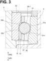
- FIG. 3 is an enlarged schematic cross-sectional view of part of a first angular contact ball bearing 3 and the surrounding section.
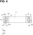
- FIG. 4 is a schematic cross-sectional view of the first angular contact ball bearing 3 according to an embodiment.
- FIG. 1 shows a state in which a rotary shaft 2 is rotatable about a first axis AX1
- FIG. 2 shows a state in which the rotation of the rotary shaft 2 is locked.
- FIG. 3 is an enlarged schematic cross-sectional view of part of a first angular contact ball bearing 3 and the surrounding section.
- FIG. 4 is a schematic cross-sectional view of the first angular contact ball bearing
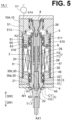
- FIG. 5 is a schematic cross-sectional view of the machining head 1A according to the first embodiment.
- FIG. 6 is an enlarged view of the section indicated by circle A1 drawn with an alternate long and short dash line in FIG. 5 .
- FIG. 7 is an enlarged view of the section indicated by circle A2 drawn with an alternate long and short dash line in FIG. 5 .
- FIG. 8 is a schematic cross-sectional view of the machining head 1A according to the first embodiment.
- FIG. 9 is an enlarged view of the section indicated by circle A3 drawn with an alternate long and short dash line in FIG. 8 . Note that FIGs. 5 and 6 show a state in which the rotary shaft 2 is rotatable about the first axis AX1, and FIGs. 8 and 9 show a state in which the rotation of the rotary shaft 2 is locked.
- the machining head 1A includes the rotary shaft locking device 10A, which is capable of locking the rotation of the rotary shaft 2, and a housing H, which surrounds the rotary shaft 2.
- the rotary shaft 2 is rotated by a first rotary drive unit 7 (see FIG. 5 if necessary) of the machining head 1A.
- the rotation of the rotary shaft 2 is locked by bringing a first contact surface C1 of the rotary shaft 2 into contact with a second contact surface C2 of a support member 4 (see FIG. 2 or FIG. 9 if necessary).
- the rotary shaft locking device 10A includes the rotary shaft 2, the first angular contact ball bearing 3, the support member 4, and a drive unit 5.
- the rotary shaft 2 includes a mounting portion 22 on which a tool (such as a milling tool or a lathe tool) will be mounted and the first contact surface C1, which is capable of coming into contact with the second contact surface C2 of the support member 4.
- a tool such as a milling tool or a lathe tool
- the rotary shaft 2 is rotatable about the first axis AX1.
- the rotary shaft 2 includes a rotary shaft body 20 and the mounting portion 22, which is located inside the rotary shaft body 20.
- the rotary shaft 2 is an assembly of a plurality of components.
- the rotary shaft 2 includes a distal end portion 21 and a rear end portion.
- the above-mentioned mounting portion 22 is located on the distal end portion 21 of the rotary shaft 2.
- the first angular contact ball bearing 3 is also located on the distal end portion 21 of the rotary shaft 2.
- the first angular contact ball bearing 3 includes an inner ring 31, an outer ring 33, and a plurality of balls 35 (in other words, a first ball group).
- a straight line that connects a contact point E1 between the inner ring 31 and each ball 35 and a contact point E2 between the outer ring 33 and the ball 35 is inclined with respect to a radial direction DR3 of the first angular contact ball bearing 3.
- the contact point E1 is located forward of the contact point E2.
- forward means a direction moving from the rear end of the rotary shaft 2 towards the distal end of the rotary shaft 2.
- “rearward” means a direction moving from the distal end of the rotary shaft 2 towards the rear end of the rotary shaft 2.
- the inner ring 31 is supported by the rotary shaft 2. More specifically, the inner ring 31 is secured to the rotary shaft 2. In the embodiment illustrated in FIG. 1 , the inner ring 31 is located around the distal end portion 21 of the rotary shaft 2.
- the outer ring 33 is supported by the support member 4. More specifically, the outer ring 33 is secured to the support member 4.
- the plurality of balls 35 are located between the inner ring 31 and the outer ring 33.
- the inner ring 31 is movable relative to the outer ring 33 in the direction parallel to the first axis AX1.
- the precompression that acts on the plurality of balls 35 changes.
- the first angular contact ball bearing 3 may include a plurality of angular contact ball bearing assemblies 30.
- Each angular contact ball bearing assembly 30 includes the inner ring 31, the outer ring 33, and the plurality of balls 35.
- the plurality of angular contact ball bearing assemblies 30 are located one next to the other in the direction parallel to the first direction DR1.
- the first angular contact ball bearing 3 is constituted by the plurality of angular contact ball bearing assemblies 30 located one next to the other in the direction parallel to the first direction DR1.
- the first angular contact ball bearing 3 may include one angular contact ball bearing assembly 30.
- the support member 4 includes the second contact surface C2, which is capable of coming into contact with the first contact surface C1.
- the first contact surface C1 of the rotary shaft 2 comes into contact with the second contact surface C2 of the support member 4, the rotation of the rotary shaft 2 about the first axis AX1 is locked (see FIG. 2 ).
- the first contact surface C 1 and the second contact surface C2 separate from each other, the rotation of the rotary shaft 2 about the first axis AX1 is permitted (see FIG. 1 ).
- the support member 4 rotatably supports the rotary shaft 2 through the first angular contact ball bearing 3.
- the support member 4 includes a first end wall 45, which is an end wall on the front side, a first block 46, which supports the first angular contact ball bearing 3, and a side wall 47, which covers at least a middle portion 24 of the rotary shaft 2.
- the support member 4 is an assembly of a plurality of components.
- the drive unit 5 moves the rotary shaft 2 and the inner ring 31 relative to the support member 4 and the outer ring 33 in the direction parallel to the first axis AX1.
- the rotary shaft 2 and the inner ring 31 are integrally movable relative to the support member 4 and the outer ring 33.
- the drive unit 5 may be any unit that is capable of moving a certain member relative to another member.
- the drive unit 5 is capable of moving the rotary shaft 2 relative to the support member 4 in the first direction DR1 parallel to the first axis AX1 so that the first contact surface C1 comes into contact with the second contact surface C2.
- the rotation of the rotary shaft 2 is locked (see FIG. 2 ).
- the drive unit 5 is capable of moving the inner ring 31 relative to the outer ring 33 in the first direction DR1 so that the precompression that acts on the plurality of balls 35 (in other words, the precompression that the plurality of balls 35 receive from the inner ring 31 and the outer ring 33) is reduced.
- the drive unit 5 moves the inner ring 31 by moving the rotary shaft 2, which supports the inner ring 31.
- the drive unit 5 is capable of switching from an unlocked state in which the rotation of the rotary shaft 2 is permitted (more specifically, the state in which the first contact surface C1 is separate from the second contact surface C2) to a locked state in which the rotation of the rotary shaft 2 is locked (more specifically, the state in which the first contact surface C1 is in contact with the second contact surface C2) by moving the rotary shaft 2 and the inner ring 31 relative to the support member 4 and the outer ring 33 in the first direction DR1.
- First precompression that acts on the plurality of balls 35 is smaller than second precompression that acts on the plurality of balls 35 (in other words, the second precompression that the plurality of balls 35 receive from the inner ring 31 and the outer ring 33) in the unlocked state.
- the first precompression may be approximately zero.
- the "unlocked state” means the state in which the rotary shaft 2 is rotatable about the first axis AX1
- the "locked state” means the state in which the rotary shaft 2 cannot rotate about the first axis AX1.
- the drive unit 5 moves the rotary shaft 2 and the inner ring 31 relative to the support member 4 and the outer ring 33 in the first direction DR1. This locks the rotation of the rotary shaft 2 and also reduces the precompression that acts on the plurality of balls 35. In this manner, in the state in which the rotation of the rotary shaft 2 is locked, the load that acts on the plurality of balls 35 of the first angular contact ball bearing 3 is reduced.
- moving the rotary shaft 2 and the inner ring 31 relative to the support member 4 and the outer ring 33 in the first direction DR1 may form a gap G (see FIG. 2 ) that permits each of the plurality of balls 35 to move relative to the inner ring 31 and the outer ring 33 in any direction (in other words, all directions).
- FIG. 3 shows the state in which one of the plurality of balls 35 (hereinafter, referred to as a "first ball 35-1”) is made movable relative to the inner ring 31 and the outer ring 33 in any direction by moving the rotary shaft 2 and the inner ring 31 relative to the support member 4 and the outer ring 33 in the first direction DR1.
- a first ball 35-1 one of the plurality of balls 35
- FIG. 3 an imaginary spherical surface Q (refer to a circle drawn with an alternate long and short dash line in FIG.
- a gap formed inward of the imaginary spherical surface Q functions as the gap G, which permits the first ball 35-1 to move relative to the inner ring 31 and the outer ring 33 in any direction (in other words, all directions).
- the gap G is formed for each of the plurality of balls 35. It will be readily understood that the shape of the gap G formed for each ball 35 is not limited to a sphere.
- the fact that the movement of each of the plurality of balls 35 is permitted in the state in which the rotation of the rotary shaft 2 is locked means that the load that acts on the plurality of balls 35 from the inner ring 31 of the first angular contact ball bearing 3 is not transmitted to the outer ring 33.
- the load that acts on the plurality of balls 35 from the inner ring 31 of the first angular contact ball bearing 3 in the axial direction (in other words, the load in the second direction DR2) is not transmitted to the outer ring 33
- the load that acts on the plurality of balls 35 from the inner ring 31 of the first angular contact ball bearing 3 in the radial direction (in other words, the load in the direction perpendicular to the second direction DR2) is not transmitted to the outer ring 33.
- the above-mentioned fretting is further inhibited or reduced since the load that acts on the plurality of balls 35 from the inner ring 31 is not transmitted to the outer ring 33. Inhibiting or reducing the fretting prolongs the durability life of the rotary shaft 2 and improves the reliability of the device including the rotary shaft 2. Since the fretting of the contact surfaces between the plurality of balls 35 and the rings (31 and 33) is kept inhibited or reduced, the rotary shaft 2 is permitted to rotate about the first axis AX1 at high speed. In other words, the durability life of the rotary shaft 2 is sufficiently maintained even when the rotary shaft 2 is used in high-speed rotation.
- oil exists in the space SP between the inner ring 31 and the outer ring 33.
- the oil is supplied from, for example, an oil supply hole 33h located in the first angular contact ball bearing 3 (more specifically, the outer ring 33).
- grease may be sealed in the space SP between the inner ring 31 and the outer ring 33.
- the drive unit 5 moves the rotary shaft 2 relative to the support member 4 in the second direction DR2, which is opposite to the first direction DR1, so that the first contact surface C1 of the rotary shaft 2 separates from the second contact surface C2 of the support member 4 (see FIG. 1 ). This unlocks the rotary shaft 2. Additionally, the drive unit 5 moves the inner ring 31 relative to the outer ring 33 in the second direction DR2, so that the precompression that acts on the plurality of balls 35 is increased (see FIG. 1 ). In the embodiment illustrated in FIGs. 1 and 2 , the drive unit 5 moves the inner ring 31 by moving the rotary shaft 2, which supports the inner ring 31.
- the drive unit 5 is capable of switching the state of the rotary shaft 2 from the locked state (see FIG. 2 ) to the unlocked state (see FIG. 1 ) by moving the rotary shaft 2 and the inner ring 31 relative to the support member 4 and the outer ring 33 in the second direction DR2.
- the second precompression that acts on the plurality of balls 35 in the unlocked state is greater than the first precompression that acts on the plurality of balls 35 in the locked state.
- the drive unit 5 moves the rotary shaft 2 and the inner ring 31 relative to the support member 4 and the outer ring 33 in the second direction DR2 to unlock the rotary shaft 2 and also to increase the precompression that acts on the plurality of balls 35.
- the axial load that acts on the rotary shaft 2 is supported by the first angular contact ball bearing 3 in a suitable manner.
- the first angular contact ball bearing 3 includes the inner ring 31, the outer ring 33, and the plurality of balls 35.
- the first angular contact ball bearing 3 may include a retainer 37 (more specifically, a ring-shaped retainer), which keeps the gap between two adjacent balls 35.
- the retainer 37 includes a plurality of through-holes 37h, which receive the plurality of balls 35, respectively.
- the inner ring 31 includes a first shoulder portion 310s
- the outer ring 33 includes a second shoulder portion 330s.
- the first shoulder portion 310s moves in the direction away from the second shoulder portion 330s.
- the precompression that acts on the plurality of balls 35 is reduced.
- the rear surface of the first shoulder portion 310s includes a first curved surface 31c, which applies diagonally rearward precompression on the plurality of balls 35
- the front surface of the second shoulder portion 330s includes a second curved surface 33c, which applies diagonally forward precompression on the plurality of balls 35.
- the first angular contact ball bearing 3 has a frontal arrangement in which the first angular contact ball bearing 3 supports the axial load that acts in the direction from the distal end of the rotary shaft 2 to the rear end of the rotary shaft 2.
- the "frontal arrangement” means the arrangement that is capable of supporting the axial load that acts in the direction from the distal end of the rotary shaft 2 to the rear end of the rotary shaft 2.
- the first shoulder portion 310s of the inner ring 31 is located forward of the second shoulder portion 330s of the outer ring 33.
- the first angular contact ball bearing 3 includes a first angular contact ball bearing assembly 30a, which is a first bearing unit.
- the first angular contact ball bearing assembly 30a has the frontal arrangement in which the first angular contact ball bearing assembly 30a supports the axial load that acts in the direction from the distal end of the rotary shaft 2 to the rear end of the rotary shaft 2.
- the first angular contact ball bearing assembly 30a includes an inner ring 31a, an outer ring 33a, and a plurality of balls 35a located between the inner ring 31a and the outer ring 33a.
- the inner ring 31a of the first angular contact ball bearing assembly 30a includes the first shoulder portion 310s, and the outer ring 33a includes a counter bore 330t (in other words, a shoulderless portion), which faces the first shoulder portion 310s.
- the outer ring 33a of the first angular contact ball bearing assembly 30a includes the second shoulder portion 330s, and the inner ring 31a includes a counter bore 310t (in other words, a shoulderless portion), which faces the second shoulder portion 330s.
- the first angular contact ball bearing 3 includes a second angular contact ball bearing assembly 30b, which is a second bearing unit.
- the second angular contact ball bearing assembly 30b is located further in the second direction DR2 than the first angular contact ball bearing assembly 30a.
- the second angular contact ball bearing assembly 30b has the frontal arrangement in which the second angular contact ball bearing assembly 30b supports the axial load that acts in the direction from the distal end of the rotary shaft 2 to the rear end of the rotary shaft 2.
- the second angular contact ball bearing assembly 30b includes an inner ring 31b, an outer ring 33b, and a plurality of balls 35b, which are located between the inner ring 31b and the outer ring 33b.
- the first angular contact ball bearing assembly 30a located on the distal end portion 21 of the rotary shaft 2 has the frontal arrangement
- the second angular contact ball bearing assembly 30b located on the distal end portion 21 of the rotary shaft 2 has the frontal arrangement
- the drive unit 5 is capable of moving the rotary shaft 2, the inner ring 3 1a of the first angular contact ball bearing assembly 30a, and the inner ring 31b of the second angular contact ball bearing assembly 30b relative to the support member 4, the outer ring 33a of the first angular contact ball bearing assembly 30a, and the outer ring 33b of the second angular contact ball bearing assembly 30b in the first direction DR1.
- Such relative movement causes the first contact surface C1 to come into contact with the second contact surface C2 with the precompression that acts on the plurality of balls (35a and 35b) reduced (typically, with each of the plurality of balls 35 allowed to move relative to the outer ring 33 and the inner ring 31 in any direction).
- the first angular contact ball bearing 3 located on the distal end portion 21 of the rotary shaft 2 includes two angular contact ball bearing assemblies (30a and 30b), which have the frontal arrangement.
- the first angular contact ball bearing 3, which is located on the distal end portion 21 of the rotary shaft 2 may include three or more angular contact ball bearing assemblies having the frontal arrangement.
- a first spacer 361 is located between the inner ring 31a of the first angular contact ball bearing assembly 30a and the inner ring 31b of the second angular contact ball bearing assembly 30b.
- the first spacer 361 maintains the gap between the inner ring 31a and the inner ring 31b.
- a second spacer 362 is located between the outer ring 33a of the first angular contact ball bearing assembly 30a and the outer ring 33b of the second angular contact ball bearing assembly 30b.
- the second spacer 362 maintains the gap between the outer ring 33a and the outer ring 33b. Note that these spacers (361 and 362) may be omitted.
- a milling tool T1 is mounted on the mounting portion 22 of the rotary shaft 2.
- a lathe tool T2 is mounted on the mounting portion 22 of the rotary shaft 2. Changing the milling tool T1 to the lathe tool T2 or changing the lathe tool T2 to the milling tool T1 is performed using, for example, an automatic tool exchanger.
- the drive unit 5 moves the rotary shaft 2 and the inner ring 31 relative to the support member 4 and the outer ring 33 in the first direction DR1.
- the first direction DR1 is the direction moving from a rear end portion 26 of the rotary shaft 2 towards the distal end portion 21 of the rotary shaft 2.
- the drive unit 5 moves the rotary shaft 2 and the inner ring 31 relative to the support member 4 and the outer ring 33 in the second direction DR2.
- the second direction DR2 is the direction moving from the distal end portion 21 of the rotary shaft 2 to the rear end portion 26 of the rotary shaft 2.
- the drive unit 5 includes a first movable member 510, which directly or indirectly presses the rotary shaft 2.
- the first movable member 510 is capable of pressing the rotary shaft 2 in the first direction DR1.
- the first movable member 510 is also capable of pressing the rotary shaft 2 in the second direction DR2.
- the first movable member 510 is located rearward of (more specifically, further in the second direction DR2 than) the first angular contact ball bearing 3.
- the structure forward of the first angular contact ball bearing 3 is simplified. As a result, the distance between the distal end of the rotary shaft 2 and the first angular contact ball bearing 3 is reduced. The reduction in the distance between the distal end of the rotary shaft 2 and the first angular contact ball bearing 3 improves the radial stiffness of the rotary shaft 2. In this case, the milling tool T1 mounted on the rotary shaft 2 is rotated about the first axis AX1 in a stable manner.
- the drive unit 5 includes a first drive unit 51, which moves the first movable member 510.
- the first drive unit 51 includes a first oil chamber 513 and a first pipe 514, which supplies oil to the first oil chamber 513.
- the first drive unit 51 may include a first valve V1, which controls the flow direction of the oil in the first pipe 514.
- the first movable member 510 when the oil is supplied from the first pipe 514 to the first oil chamber 513, the first movable member 510 moves in the first direction DR1.
- the first movable member 510 presses the rotary shaft 2 in the first direction DR1.
- the first movable member 510 includes a first piston 511, which is hydraulically driven.
- the first movable member 510 may be constituted by one component, or may be constituted by an assembly of a plurality of components.
- the first movable member 510 presses the rotary shaft 2 through a second angular contact ball bearing 6, which is located on the rear end portion 26 of the rotary shaft 2.
- the first movable member 510 may directly press the rotary shaft 2.
- the movable member 510 includes a first pressing portion 510a and a second pressing portion 510b.
- first pressing portion 510a of the first movable member 510 presses the rotary shaft 2 in the first direction DR1 through the second angular contact ball bearing 6.
- second pressing portion 510b of the first movable member 510 presses the rotary shaft 2 in the second direction DR2 through the second angular contact ball bearing 6.
- the first movable member 510 (more specifically, the first piston 511) includes a pressure receiving surface 511s, which receives the hydraulic pressure.
- the first drive unit 51 includes a plurality of rolling elements 517, which are located around the first movable member 510 and guide the movement of the first movable member 510.
- the plurality of rolling elements 517 are located between the outer circumferential surface of the first movable member 510 and the inner circumferential surface of the support member 4.
- the first drive unit 51 includes a first urging member 516 (for example, a spring), which applies an urging force to the first movable member 510.
- the first urging member 516 urges the first movable member 510 in the second direction DR2.
- the first urging member 516 is located between the first movable member 510 and the support member 4.
- the first movable member 510 moves in the second direction DR2 by the urging force of the first urging member 516.
- the first movable member 510 presses the rotary shaft 2 in the second direction DR2.
- the first movable member 510 which receives an urging force from the first urging member 516, moves the rotary shaft 2 and the inner ring 31 relative to the support member 4 and the outer ring 33 in the second direction DR2 so that the first contact surface C1 of the rotary shaft 2 separates from the second contact surface C2 of the support member 4 and so that the precompression that acts on the plurality of balls 35 of the first angular contact ball bearing 3 is increased. This unlocks the rotary shaft 2.
- the first urging member 516 applies an urging force to the first movable member 510, the rotary shaft 2, and the inner ring 31 in the second direction DR2 (in other words, the direction opposite to the first direction DR1).
- the plurality of balls 35 receive, from the inner ring 31, the precompression that corresponds to the amount of the urging force applied by the first urging member 516.
- the drive unit 5 moves the rotary shaft 2 and the inner ring 31 relative to the support member 4 and the outer ring 33 in the first direction DR1 against the urging force of the first urging member 516, so that the precompression that acts on the plurality of balls 35 is reduced.
- the rotary shaft locking device 10A includes the second angular contact ball bearing 6, which is located on the rear end portion 26 of the rotary shaft 2.
- the second angular contact ball bearing 6 includes a second inner ring 61, a second outer ring 63, and a plurality of balls 65 (in other words, a second ball group).
- the second inner ring 61 is supported by the rotary shaft 2. More specifically, the second inner ring 61 is secured to the rotary shaft 2. In the embodiment illustrated in FIG. 5 , the second inner ring 61 is located around the rear end portion 26 of the rotary shaft 2.
- the second outer ring 63 is supported by the first movable member 510. More specifically, the second outer ring 63 is secured to the first movable member 510.
- the plurality of balls 65 are located between the second inner ring 61 and the second outer ring 63.
- the second angular contact ball bearing 6 may include a plurality of angular contact ball bearing assemblies 60.
- Each angular contact ball bearing assembly 60 includes the second inner ring 61, the second outer ring 63, and the plurality of balls 65.
- the second angular contact ball bearing 6 is constituted by the plurality of angular contact ball bearing assemblies 60 located one next to the other in the direction parallel to the first direction DR1.
- the second angular contact ball bearing 6 may include one angular contact ball bearing assembly 60.
- the second angular contact ball bearing 6 has a back arrangement in which the second angular contact ball bearing 6 supports the axial load that acts in the direction from the rear end of the rotary shaft 2 to the distal end of the rotary shaft 2 (in other words, the axial load in the first direction DR1).
- the second angular contact ball bearing 6 located on the rear end portion 26 of the rotary shaft 2 preferably has the back arrangement.
- the "back arrangement” means the arrangement that is capable of supporting the axial load that acts in the direction from the rear end of the rotary shaft 2 to the distal end of the rotary shaft 2.
- a third shoulder portion 610s of the second inner ring 61 is located rearward of a fourth shoulder portion 630s of the second outer ring 63.
- precompression acts on the plurality of balls 65.
- the drive unit 5 is capable of moving the entire second angular contact ball bearing 6, the rotary shaft 2, and the inner ring 31 of the first angular contact ball bearing 3 relative to the support member 4 and the outer ring 33 of the first angular contact ball bearing 3 in the first direction DR1.
- the precompression that acts on the plurality of balls 35 (in other words, the first ball group) is reduced.
- the precompression that acts on the plurality of balls 65 in other words, the second ball group may be reduced or approximately maintained.
- a front end face 31f of the inner ring 31 is located forward of (in other words, further in the first direction DR1 than) a front end face 33f of the outer ring 33.
- the position of the front end face 31f of the inner ring 31 in the direction of the first axis AX1 is approximately aligned with the position of the front end face 33f of the outer ring 33 in the direction of the first axis AX1.
- the machining head 1A includes the first rotary drive unit 7, which rotates the rotary shaft 2 about the first axis AX1.
- the first rotary drive unit 7 may be a first motor.
- the first rotary drive unit 7 (more specifically, the first motor) includes a stator 71 and a rotor 73. In this case, when current is supplied to the stator 71, the rotor 73 rotates about the first axis AX1 by electromagnetic action.
- the stator 71 is secured to the support member 4, and the rotor 73 is secured to the rotary shaft 2.
- the rotor 73 is located on the middle portion 24 of the rotary shaft 2. In the embodiment illustrated in FIG. 5 , the rotor 73 is located rearward of the first angular contact ball bearing 3 and forward of the second angular contact ball bearing 6.
- the first movable member 510 which presses the rotary shaft 2 is located rearward of the stator 71.
- the first movable member 510, which presses the rotary shaft 2 may be located forward of the stator 71. In this case, the first movable member 510 directly presses the rotary shaft 2 without the second angular contact ball bearing 6.
- the rotary shaft locking device 10A includes a locking mechanism C that locks the rotation of the rotary shaft 2.
- the locking mechanism C includes the first contact surface C1 of the rotary shaft 2 and the second contact surface C2 of the support member 4.
- the first contact surface C1 includes a first inclined surface M1, which is inclined with respect to the first axis AX1
- the second contact surface C2 includes a second inclined surface M2, which is inclined with respect to the first axis AX1.
- the state in which the first inclined surface M1 and the second inclined surface M2 are in contact with each other corresponds to the locked state.
- the state in which the first inclined surface M1 and the second inclined surface M2 are separate from each other corresponds to the unlocked state.
- first inclined surface M1 and the second inclined surface M2 are located forward of (in other words, further in the first direction DR1 than) the first angular contact ball bearing 3.
- the first inclined surface M1 is an annular inclined surface formed on the outer circumferential surface of the rotary shaft 2.
- the outer diameter of the first inclined surface M1 is reduced toward the front (in other words, toward the distal end 2a of the rotary shaft 2).
- the second inclined surface M2 is an annular inclined surface formed on the inner circumferential surface of the support member 4.
- the second inclined surface M2 is located on the first end wall 45 of the support member 4.
- the inner diameter of the second inclined surface M2 is reduced toward the front (in other words, toward the distal end 2a of the rotary shaft 2).
- the rotary shaft 2 includes the rotary shaft body 20, the mounting portion 22 on which a tool T is mounted, and a rod-like member 28, which is coupled to the mounting portion 22.
- a mounting portion drive unit 8 of the machining head 1A presses the rod-like member 28 in the first direction DR1
- the rod-like member 28 and the mounting portion 22 move relative to the rotary shaft body 20 in the first direction DR1.
- the tool T mounted on the mounting portion 22 can be changed to another tool.
- an urging member 29 for example, a disc spring located on the rotary shaft 2 presses the rod-like member 28 in the second direction DR2. In this manner, the rod-like member 28 and the mounting portion 22 move relative to the rotary shaft body 20 in the second direction DR2.
- the distal end portion 21 of the rotary shaft 2 includes a recessed portion 21b, which faces a projecting portion 45b formed on the first end wall 45 of the support member 4.
- the recessed portion 21b and the projecting portion 45b form a labyrinth structure that prevents the entry of liquid.
- the gap between the recessed portion 21b and the projecting portion 45b increases when the rotary shaft 2 moves relative to the support member 4 in the first direction DR1 (see FIG. 9 ).
- the housing H includes the side wall 47, which covers at least the middle portion 24 of the rotary shaft 2.
- the housing H includes the first end wall 45.
- a first hole 45h is formed in the first end wall 45.
- the rotary shaft 2 is located to pass through the first hole 45h.
- the inner surface of the first hole 45h functions as the above-mentioned second contact surface C2 (more specifically, the second inclined surface M2).
- FIG. 10 is a schematic cross-sectional view of the machining head 1B according to the second embodiment.
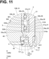
- FIG. 11 is an enlarged view of the section indicated by circle A4 drawn with an alternate long and short dash line in FIG. 10 .
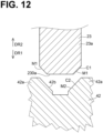
- FIG. 12 is a schematic diagram illustrating the state in which a first coupling 23 and a second coupling 42 are disengaged from each other.
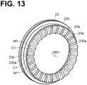
- FIG. 13 is a schematic perspective view of the first coupling 23 according to an embodiment.
- FIG. 14 is a schematic cross-sectional view of the machining head 1B according to the second embodiment.
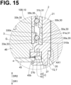
- FIG. 15 is an enlarged view of the section indicated by circle A5 drawn with an alternate long and short dash line in FIG. 14 .
- FIG. 16 is a schematic diagram illustrating the state in which the first coupling 23 and the second coupling 42 are engaged with each other.
- the structure of the locking mechanism C which locks the rotation of the rotary shaft 2 differs from the structure of the locking mechanism C according to the first embodiment.
- the second embodiment is identical to the first embodiment in other aspects.
- the locking mechanism C will mainly be described, and redundant descriptions of structures other than the locking mechanism C are omitted.
- the rotary shaft locking device 10B includes (1) the rotary shaft 2, which includes the mounting portion 22 on which the tool T will be mounted and first contact surfaces C1 and is rotatable about the first axis AX1, (2) the first angular contact ball bearing 3, which includes the inner ring 31 supported by the rotary shaft 2, the outer ring 33, and the plurality of balls 35 located between the inner ring 31 and the outer ring 33, (3) the support member 4, which includes second contact surfaces C2 that come into contact with the first contact surfaces C1 to lock the rotation of the rotary shaft 2 and rotatably supports the rotary shaft 2 through the first angular contact ball bearing 3, and (4) the drive unit 5, which moves the rotary shaft 2 and the inner ring 31 relative to the support member 4 and the outer ring 33 in the first direction DR1 parallel to the first axis AX1 so that the first contact surfaces C1 come into contact with the second contact surfaces C2 and so that the precompression that acts on the plurality of balls 35 is reduced.
- the machining head 1B includes the first rotary drive unit 7, which rotates the rotary shaft 2 about the first axis AX1, the housing H, which surrounds the rotary shaft 2, and the above-mentioned rotary shaft locking device 10B.
- the second embodiment has the same advantages as the first embodiment.
- the rotary shaft locking device 10B includes the locking mechanism C that locks the rotation of the rotary shaft 2.
- the locking mechanism C includes the first coupling 23 and the second coupling 42.
- the rotary shaft 2 includes the first coupling 23, and the support member 4 includes the second coupling 42.
- the first coupling 23 (that is, the coupling on the rotary shaft 2) includes the first contact surfaces C1.
- the first contact surfaces C1 include first inclined surfaces M1.
- the second coupling 42 (that is, the coupling on the support member 4) includes the second contact surfaces C2.
- the second contact surfaces C2 include second inclined surfaces M2.
- the engagement between the first coupling 23 and the second coupling 42 locks the rotation of the rotary shaft 2.
- the state in which the first coupling 23 and the second coupling 42 are engaged with each other corresponds to the locked state, and the state in which the first coupling 23 and the second coupling 42 are disengaged from each other corresponds to the unlocked state.
- the drive unit 5 switches the state of the rotary shaft 2 between the locked state and the unlocked state.
- the rotary shaft 2 includes the rotary shaft body 20 and the first coupling 23, and the first coupling 23 is secured to the rotary shaft body 20 using a fastener 27.
- the first coupling 23 is located forward of the first angular contact ball bearing 3.
- the second coupling 42 is located forward of the first coupling 23.
- the second coupling 42 is a fixed coupling that is fixed to the first block 46 of the support member 4.
- the second coupling 42 is located on the first end wall 45 of the support member 4.
- the second coupling 42 may be located on a different section of the support member 4.
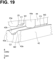
- the first coupling 23 includes a first tooth 23a, which projects toward the second coupling 42.
- the first tooth 23a has a distal end face 230a.
- the distal end face 230a will be received by a recessed portion 42b of the second coupling 42.
- the first coupling 23 includes first teeth 23a each of which includes first contact surfaces C1 (more specifically, first inclined surfaces M1).
- the first inclined surfaces M1 are located on both sides of the distal end face 230a of each of the first teeth 23 a of the first coupling 23.
- the first coupling 23 may include the plurality of first teeth 23a and a first annular body 23c on which the plurality of first teeth 23a are located.
- the first teeth 23a project from the first annular body 23c in the first direction DR1.
- the second coupling 42 includes second teeth 42a, which project toward the first coupling 23.
- the second coupling 42 includes the recessed portion 42b formed between two adjacent second teeth 42a.
- each of the second teeth 42a of the second coupling 42 has the second contact surface C2 (more specifically, the second inclined surface M2).
- the second coupling 42 may include the plurality of second teeth 42a and a second annular body on which the plurality of second teeth 42a are located.
- the engagement between the first coupling 23 and the second coupling 42 locks the rotation of the rotary shaft 2.
- the stiffness of the rotary shaft 2 in the state in which the rotation of the rotary shaft 2 is locked is improved.
- the positioning accuracy of the rotary shaft 2 in the rotation direction about the first axis AX1 is improved.
- the turning is performed with higher accuracy.
- FIG. 17 is a schematic cross-sectional view of the machining head 1C according to the third embodiment.
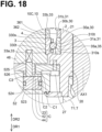
- FIG. 18 is an enlarged view of the section indicated by circle A6 drawn with an alternate long and short dash line in FIG. 17 .
- FIG. 19 is a schematic diagram illustrating the state in which the first coupling 23 and the second coupling 42 are disengaged from each other.
- FIG. 20 is a schematic cross-sectional view of the machining head 1C according to the third embodiment.
- FIG. 21 is an enlarged view of the section indicated by circle A7 drawn with an alternate long and short dash line in FIG. 20 .
- FIG. 22 is a schematic diagram illustrating the state in which the first coupling 23 and a third coupling 44 are engaged with the second coupling 42.
- the differences from the first embodiment and the second embodiment will mainly be described. Meanwhile, in the third embodiment, redundant descriptions of items that have already been described in the first embodiment or the second embodiment are omitted. Therefore, in the third embodiment, even without an explicit description, it will be readily understood that the items that have already been described in the first embodiment or the second embodiment may be applied to the third embodiment.
- the structure of the locking mechanism C which locks the rotation of the rotary shaft 2, and the structure associated with the locking mechanism C differ from the structure of the locking mechanism C and the structure associated with the locking mechanism C according to the first embodiment and the second embodiment.
- the third embodiment is identical to the first embodiment or the second embodiment in other aspects. For this reason, in the third embodiment, the locking mechanism C and the structure associated with the locking mechanism C will mainly be described, and redundant descriptions of structures other than the above are omitted.
- the rotary shaft locking device 10C includes (1) the rotary shaft 2, which includes the mounting portion 22 on which the tool T will be mounted and the first contact surfaces C1 and is rotatable about the first axis AX1, (2) the first angular contact ball bearing 3, which includes the inner ring 31 supported by the rotary shaft 2, the outer ring 33, and the plurality of balls 35 located between the inner ring 31 and the outer ring 33, (3) the support member 4, which includes the second contact surfaces C2 that come into contact with the first contact surfaces C 1 to lock the rotation of the rotary shaft 2 and rotatably supports the rotary shaft 2 through the first angular contact ball bearing 3, and (4) the drive unit 5, which moves the rotary shaft 2 and the inner ring 31 relative to the support member 4 and the outer ring 33 in the first direction DR1 parallel to the first axis AX1 so that the first contact surfaces C1 come into contact with the second contact surfaces C2 and so that the precompression that acts on the plurality of balls 35 is reduced
- the machining head 1C includes the first rotary drive unit 7, which rotates the rotary shaft 2 about the first axis AX1, the housing H, which surrounds the rotary shaft 2, and the above-mentioned rotary shaft locking device 10C.
- the third embodiment has the same advantages as the first embodiment.
- the rotary shaft locking device 10C includes the locking mechanism C that locks the rotation of the rotary shaft 2.
- the locking mechanism C includes the first coupling 23, the second coupling 42, and the third coupling 44.
- the rotary shaft 2 includes the first coupling 23, and the support member 4 includes the second coupling 42 and the third coupling 44.
- the second coupling 42 is movable relative to the third coupling 44.
- the second coupling 42 is a piston driven by hydraulic pressure.
- the first coupling 23 (that is, the coupling on the rotary shaft 2) includes the first contact surfaces C1.
- the first contact surfaces C1 include the first inclined surfaces M1.
- the second coupling 42 (that is, the coupling on the support member 4) includes the second contact surfaces C2, and the third coupling 44 (that is, the other coupling on the support member 4) includes third contact surfaces C3.
- the second contact surfaces C2 include the second inclined surfaces M2, and the third contact surfaces C3 include third inclined surfaces M3.
- the engagement of the second coupling 42 with both the first coupling 23 and the third coupling 44 locks the rotation of the rotary shaft 2.
- the state in which the second coupling 42 is engaged with both the first coupling 23 and the third coupling 44 corresponds to the locked state
- the state in which the second coupling 42 is disengaged from the first coupling 23 corresponds to the unlocked state.
- the unlocked state corresponds to the unlocked state
- the second coupling 42 and the third coupling 44 may be completely disengaged, or the second coupling 42 and the third coupling 44 do not necessarily have to be completely disengaged.
- the drive unit 5 switches the state of the rotary shaft 2 between the locked state and the unlocked state.
- the drive unit 5 includes the first drive unit 51, which moves the first movable member 510, which presses the rotary shaft 2, and a second drive unit 52, which moves the second coupling 42.
- each of the first drive unit 51 and the second drive unit 52 functions as part of the drive unit 5, which switches the state of the rotary shaft 2 from the unlocked state to the locked state.
- the second drive unit 52 moves the second coupling 42 so that the second coupling 42 engages with both the first coupling 23 and the third coupling 44.
- the second drive unit 52 applies a drive force to the second coupling 42, which functions as a second movable member.
- the second drive unit 52 includes a second oil chamber 523 and a second pipe 524, which supplies oil to the second oil chamber 523.
- the second drive unit 52 may include a second valve V2 (see FIG. 17 ), which controls the flow direction of the oil in the second pipe 524.
- the second drive unit 52 includes a second urging member 525 (for example, a spring), which urges the second coupling 42 in the direction away from the first coupling 23.
- the second drive unit 52 includes a pressing member 526, which presses the second coupling 42 in the direction away from the first coupling 23 (more specifically, in the first direction DR1) by the urging force of the second urging member 525.
- the first inclined surfaces M1 of the first coupling 23 are in contact with the second inclined surfaces M2 of the second coupling 42.
- the second inclined surfaces M2 of the second coupling 42 are in contact with the third inclined surfaces M3 of the third coupling 44.
- a motion stroke L1 of the inner ring 31 (that is, the motion stroke L1 of the inner ring 31 when the unlocked state is switched to the locked state) is smaller than a motion stroke L2 of the second coupling 42 (that is, the motion stroke L2 of the second coupling 42 when the unlocked state is switched to the locked state).
- the first coupling 23 and the second coupling 42 are switched from the disengaged state to the engaged state mainly by the second drive unit 52.
- the couplings (23, 42) including high-stiffness teeth with a high tooth height can be employed without being restricted by the structure of the first angular contact ball bearing 3 (for example, the amount that the inner ring 31 can move relative to the outer ring 33 in the first direction D1, in other words, the amount of backlash of the first angular contact ball bearing 3).
- the motion stroke L1 of the inner ring 31 (that is, the motion stroke L1 of the inner ring 31 when the unlocked state is switched to the locked state) is also preferably smaller than the motion stroke L2 of the second coupling 42 (that is, the motion stroke L2 of the second coupling 42 when the unlocked state is switched to the locked state) (see FIG. 26 ).
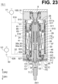
- FIG. 23 is a schematic cross-sectional view of the machining head 1D according to the fourth embodiment.
- FIG. 24 is an enlarged view of the section indicated by circle A8 drawn with an alternate long and short dash line in FIG. 23 .
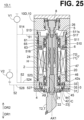
- FIG. 25 is a schematic cross-sectional view of the machining head 1D according to the fourth embodiment.
- FIG. 26 is an enlarged view of the section indicated by circle A9 drawn with an alternate long and short dash line in FIG. 25 .
- FIG. 27 is a schematic diagram illustrating the first coupling 23 and the third coupling 44 according to an embodiment. In FIG.
- FIG. 28 is a schematic diagram illustrating the second coupling 42 according to an embodiment.
- the broken line indicates the outline of the second coupling 42.
- the illustration of the teeth (42a) in the region surrounded by the broken line is omitted.
- the differences from the first embodiment, the second embodiment, and the third embodiment will mainly be described. Meanwhile, in the fourth embodiment, redundant descriptions of items that have already been described in the first embodiment, the second embodiment, or the third embodiment are omitted. Therefore, in the fourth embodiment, even without an explicit description, it will be readily understood that the items that have already been described in the first embodiment, the second embodiment, or the third embodiment may be applied to the fourth embodiment.
- the switching of the unlocked state to the locked state includes moving the second coupling 42 rearward (more specifically, in the second direction DR2).
- the switching of the unlocked state to the locked state includes moving the second coupling 42 forward (more specifically, in the first direction DR1).
- differences from the first embodiment to the third embodiment will mainly be described regarding the locking mechanism C, the first drive unit 51, the second drive unit 52, the first coupling 23, the second coupling 42, and the third coupling 44, and redundant descriptions of other structures are omitted.
- the rotary shaft locking device 10D includes (1) the rotary shaft 2, which includes the mounting portion 22 on which the tool T will be mounted and the first contact surfaces C1 and is rotatable about the first axis AX1, (2) the first angular contact ball bearing 3, which includes the inner ring 31 supported by the rotary shaft 2, the outer ring 33, and the plurality of balls 35 located between the inner ring 31 and the outer ring 33, (3) the support member 4, which includes the second contact surfaces C2 that come into contact with the first contact surfaces C1 to lock the rotation of the rotary shaft 2 and rotatably supports the rotary shaft 2 through the first angular contact ball bearing 3, and (4) the drive unit 5, which moves the rotary shaft 2 and the inner ring 31 relative to the support member 4 and the outer ring 33 in the first direction DR1 parallel to the first axis AX1 so that the first contact surfaces C1 come into contact with the second contact surfaces C2 and so that the precompression that acts on the plurality of balls 35 is reduced
- the machining head 1D includes the first rotary drive unit 7, which rotates the rotary shaft 2 about the first axis AX1, the housing H, which surrounds the rotary shaft 2, and the above-mentioned rotary shaft locking device 10D.
- the fourth embodiment has the same advantages as the first embodiment.
- the rotary shaft locking device 10D includes the locking mechanism C that locks the rotation of the rotary shaft 2.
- the locking mechanism C includes the first coupling 23, the second coupling 42, and the third coupling 44.
- the rotary shaft 2 includes the first coupling 23, and the support member 4 includes the second coupling 42 and the third coupling 44.
- the second coupling 42 is movable relative to the third coupling 44.
- the state in which the second coupling 42 is engaged with both the first coupling 23 and the third coupling 44 corresponds to the locked state
- the state in which the second coupling 42 is disengaged from the first coupling 23 corresponds to the unlocked state.
- the unlocked state corresponds to the unlocked state
- the second coupling 42 and the third coupling 44 may be completely disengaged, or the second coupling 42 and the third coupling 44 do not necessarily have to be completely disengaged.
- the second coupling 42 driven by the second drive unit 52 is located rearward of (more specifically, further in the second direction DR2 than) the first coupling 23 and the third coupling 44.
- the distance between the distal end of the rotary shaft 2 and the first angular contact ball bearing 3 is reduced, and the radial stiffness of the rotary shaft 2 is improved.
- the milling tool T1 mounted on the rotary shaft 2 is rotated about the first axis AX1 in a stable manner.
- the drive unit 5 switches the state of the rotary shaft 2 between the locked state and the unlocked state.
- the drive unit 5 includes the first drive unit 51, which moves the first movable member 510, which presses the rotary shaft 2, and the second drive unit 52, which moves the second coupling 42.
- each of the first drive unit 51 and the second drive unit 52 functions as part of the drive unit 5, which switches the state of the rotary shaft 2 from the unlocked state to the locked state in which the rotary shaft 2 is locked.
- the first drive unit 51 includes the first oil chamber 513 and the first pipe 514, which supplies oil to the first oil chamber 513.
- the first drive unit 51 may include the first valve V1, which controls the flow direction of the oil in the first pipe 514.
- the first drive unit 51 drives the first movable member 510.
- the first movable member 510 presses the rotary shaft 2 through the second angular contact ball bearing 6, which is located on the rear end portion 26 of the rotary shaft 2.
- the first movable member 510 may directly press the rotary shaft 2.
- the first movable member 510 may be located forward of the stator 71.
- the first movable member 510 is located rearward of the stator 71.
- the first movable member 510 includes the first piston 511.
- the first drive unit 51 includes the plurality of rolling elements 517, which are located around the first piston 511 and guide the movement of the first piston 511.
- the first drive unit 51 includes the first urging member 516 (for example, a spring), which applies an urging force to the first movable member 510.
- the first urging member 516 urges the first movable member 510 in the second direction DR2.
- the first urging member 516 is located between the first movable member 510 and the support member 4.
- the first urging member 516 applies an urging force to the first movable member 510, the rotary shaft 2, and the inner ring 31 in the second direction DR2 (in other words, the direction opposite to the first direction DR1).
- the plurality of balls 35 receive, from the inner ring 31, the precompression that corresponds to the amount of the urging force applied by the first urging member 516.
- the second drive unit 52 moves the second coupling 42 so that the second coupling 42 engages with both the first coupling 23 and the third coupling 44.
- the second drive unit 52 applies a drive force to the second coupling 42, which functions as the second movable member.
- the second drive unit 52 includes the second oil chamber 523 and the second pipe 524, which supplies oil to the second oil chamber 523.
- the second drive unit 52 may include a valve, which controls the flow direction of the oil in the second pipe 524.
- the valve that controls the flow direction of the oil in the second pipe 524 is the same as the first valve V1, which controls the flow direction of the oil in the first pipe 514.
- the valve that controls the flow direction of the oil in the second pipe 524 may be a valve different from the first valve V1, which controls the flow direction of the oil in the first pipe 514.
- the first oil chamber 513 and the second oil chamber 523 are connected to each other through the first pipe 514 and the second pipe 524.
- the hydraulic pressure in the second oil chamber 523 is substantially equal to the hydraulic pressure in the first oil chamber 513.
- the second drive unit 52 may include a third oil chamber 527 and a third pipe 528, which supplies oil to the third oil chamber 527.
- the second drive unit 52 may include the second valve V2, which controls the flow direction of the oil in the third pipe 528.
- the second valve V2 which controls the flow direction of the oil in the third pipe 528, is a valve different from the first valve V1, which controls the flow direction of the oil in the second pipe 524.
- the flow direction of the oil in the third pipe 528 and the flow direction of the oil in the second pipe 524 may be controlled by one switching valve.
- the second drive unit 52 moves the second coupling 42 in the direction toward the first coupling 23 (in the first direction DR1 in the embodiment illustrated in FIG. 23 ).
- the second drive unit 52 moves the second coupling 42, the rotary shaft 2, and the inner ring 31 integrally in the first direction DR1 with the second coupling 42 and the first coupling 23 engaged with each other. More specifically, when the second drive unit 52 moves the second coupling 42 in the first direction DR1, the second coupling 42 presses the rotary shaft 2 in the first direction DR1 through the first coupling 23. As a result, the rotary shaft 2 and the inner ring 31, which is supported by the rotary shaft 2, move relative to the outer ring 33 in the first direction DR1.
- the precompression that acts on the plurality of balls 35 is reduced (typically, a space is formed that permits each of the plurality of balls 35 to move relative to the outer ring 33 and the inner ring 31 in any direction, and the load that acts on the plurality of balls 35 from the inner ring 31 is not transmitted to the outer ring 33).
- the second drive unit 52 in switching the state of the rotary shaft 2 from the unlocked state to the locked state, applies a first pressing force to the rotary shaft 2 in the first direction DR1, and the first drive unit 51 applies a second pressing force to the rotary shaft 2 in the second direction DR2.
- the second drive unit 52 increases the hydraulic pressure in the second oil chamber 523.
- the second coupling 42 moves in the first direction DR1
- the second coupling 42 presses the first coupling 23 and the rotary shaft 2 in the first direction DR1 (first pressing force).
- the first drive unit 51 increases the hydraulic pressure in the first oil chamber 513.
- the first movable member 510 presses the rotary shaft 2 in the second direction DR2 (second pressing force).
- the first contact surfaces C1 of the first coupling 23, which is located on the rotary shaft 2 strongly abut against the second contact surfaces C2 of the second coupling 42, which is located on the support member 4. This reinforces the locking of the rotation of the rotary shaft 2. Since the second contact surfaces C2 of the second coupling 42 reliably abut against both the first contact surfaces C1 of the first coupling 23 and the third contact surfaces C3 of the third coupling 44, the positioning accuracy of the rotary shaft 2 in the rotation direction about the first axis AX1 is improved regardless of the machining accuracy or the assembly accuracy of the couplings (23, 42, and 44).
- the first pressing force that the second drive unit 52 applies to the rotary shaft 2 in the first direction DR1 is greater than the second pressing force that the first drive unit 51 applies to the rotary shaft 2 in the second direction DR2. Since the first pressing force in the first direction DR1 is greater than the second pressing force in the second direction DR2, the rotary shaft 2 and the inner ring 31 move relative to the support member 4 and the outer ring 33 in the first direction DR1.
- the area of a pressure receiving surface 42s of the second coupling 42 facing the second oil chamber 523 is greater than the area of the pressure receiving surface 511s of the first movable member 510 facing the first oil chamber 513.
- the hydraulic pressure in the second oil chamber 523 may be made greater than the hydraulic pressure in the first oil chamber 513.
- the second drive unit 52 moves the second coupling 42 in the direction away from the first coupling 23 (in the second direction DR2 in the embodiment illustrated in FIG. 25 ).
- the second coupling 42 and the first coupling 23 are disengaged from each other.
- the second drive unit 52 decreases the hydraulic pressure in the second oil chamber 523 and increases the hydraulic pressure in the third oil chamber 527.
- the second coupling 42 moves in the second direction DR2, so that the second coupling 42 and the first coupling 23 are disengaged from each other.
- the first oil chamber 513 and the second oil chamber 523 are connected to each other through the first pipe 514 and the second pipe 524.
- the rotary shaft 2 includes the rotary shaft body 20 and the first coupling 23, which is secured to the rotary shaft body 20 using the fastener 27. Additionally, in the embodiment illustrated in FIG. 26 , the first coupling 23 is located forward of the first angular contact ball bearing 3.
- the first coupling 23 includes the first teeth 23a.
- the first teeth 23a project toward the second coupling 42.
- the first coupling 23 may include the plurality of first teeth 23a and the first annular body 23c on which the plurality of first teeth 23a are located.
- the first teeth 23a each have the distal end face 230a.
- the distal end faces 230a will be received by the recessed portions 42b of the second coupling 42.
- each of the first teeth 23a has the first contact surfaces C1 (more specifically, the first inclined surfaces M1).
- the first inclined surfaces M1 are located on both sides of the distal end face 230a of each of the first teeth 23 a.
- the support member 4 includes the first block 46, which supports the outer ring 33 of the first angular contact ball bearing 3, and the second coupling 42, which is movable relative to the first block 46.
- the second coupling 42 is a movable coupling that is movable relative to the first block 46.
- the second coupling 42 is, for example, a piston driven by hydraulic pressure.
- the second coupling 42 includes the second teeth 42a.
- the second teeth 42a project toward the first coupling 23.
- the second coupling 42 may include the plurality of second teeth 42a and a second annular body 42c on which the plurality of second teeth 42a are located.
- the second coupling 42 includes the recessed portions 42b each of which is formed between two adjacent second teeth 42a.
- each of the second teeth 42a has the second contact surfaces C2 (more specifically, the second inclined surfaces M2).
- the second inclined surfaces M2 are located on both sides of a distal end face 420a of each of the second teeth 42a.
- the second contact surfaces C2 of the second coupling 42 abut against the first contact surfaces C1 of the first coupling 23 and the third contact surfaces C3 of the third coupling 44.
- the second contact surfaces C2 of the second coupling 42 are separate from the first contact surfaces C1 of the first coupling 23 and the third contact surfaces C3 of the third coupling 44.
- the support member 4 includes the third coupling 44.
- the third coupling 44 is a fixed coupling fixed to the first block 46.
- the third coupling 44 is located outward of and concentrically to the first coupling 23.
- the third coupling 44 includes third teeth 44a.
- the third teeth 44a project toward the second coupling 42.
- the third coupling 44 may include the plurality of third teeth 44a and a third annular body 44c on which the plurality of third teeth 44a are located.
- the third teeth 44a each have a distal end face 440a.
- the distal end faces 440a will be received by the recessed portions 42b of the second coupling 42.
- each of the third teeth 44a has the third contact surfaces C3 (more specifically, the third inclined surfaces M3).
- the third inclined surfaces M3 are located on both sides of the distal end face 440a of each of the third teeth 44a of the third coupling 44.
- the support member 4 includes the first end wall 45, the second coupling 42, the third coupling 44, the first block 46, which supports the outer ring 33 of the first angular contact ball bearing 3, and the side wall 47, which covers at least the middle portion 24 of the rotary shaft 2.
- FIG. 29 is a schematic perspective view of the multi-tasking machine 100 according to the fifth embodiment.
- the multi-tasking machine 100 includes the machining head 1, a workpiece holding device 120, a machining head drive unit 130, and a controller 140.
- the multi-tasking machine means a machine tool that can perform different kinds of machining operations.
- the multi-tasking machine 100 is capable of selectively executing at least turning and milling.
- the multi-tasking machine 100 may include an automatic tool changer 190, which automatically changes the tool mounted on the rotary shaft 2 to another tool.
- the machining head 1 includes the rotary shaft locking device 10, the first rotary drive unit 7, which rotates the rotary shaft 2 about the first axis AX1, and the housing H, which surrounds the rotary shaft 2.
- the rotary shaft locking device 10 may be the rotary shaft locking device 10A according to the first embodiment, the rotary shaft locking device 10B according to the second embodiment, the rotary shaft locking device 10C according to the third embodiment, the rotary shaft locking device 10D according to the fourth embodiment, or other rotary shaft locking devices.
- the rotary shaft locking device 10 includes (1) the rotary shaft 2, which includes the mounting portion 22 on which the tool T will be mounted and the first contact surface(s) C1 and is rotatable about the first axis AX1, (2) the first angular contact ball bearing 3, which includes the inner ring 31 supported by the rotary shaft 2, the outer ring 33, and the plurality of balls 35 located between the inner ring 31 and the outer ring 33, (3) the support member 4, which includes the second contact surface(s) C2 that comes into contact with the first contact surface(s) C1 to lock the rotation of the rotary shaft 2 and rotatably supports the rotary shaft 2 through the first angular contact ball bearing 3, and (4) the drive unit 5, which moves the rotary shaft 2 and the inner ring 31 relative to the support member 4 and the outer ring 33 in the first direction DR1 parallel to the first axis AX1.
- the workpiece holding device 120 holds a workpiece.
- the workpiece holding device 120 includes a workpiece holder 121 (for example, a chuck), which holds the workpiece, a second support member 123, which rotatably supports the workpiece holder 121 about a second axis AX2, and a second rotary drive unit 125 (for example, a second motor), which rotates the workpiece holder 121 about the second axis AX2.
- a second rotary drive unit 125 for example, a second motor
- the machining head drive unit 130 moves the machining head 1 relative to the workpiece holding device 120.
- the machining head drive unit 130 may be a drive unit that can move the machining head 1 three-dimensionally. More specifically, the machining head drive unit 130 may be capable of moving the machining head 1 along a Z axis, an X axis, which is perpendicular to the Z axis, and a Y axis, which is perpendicular to both the X axis and the Z axis. In the embodiment illustrated in FIG. 29 , the machining head drive unit 130 is supported by the base 150.
- the controller 140 controls the operation of the drive unit 5, the first rotary drive unit 7, the second rotary drive unit 125, and the machining head drive unit 130.
- the machining head drive unit 130 moves the machining head 1 relative to the workpiece holding device 120. In this manner, the tool T mounted on the rotary shaft 2 is moved toward or away from the workpiece.
- the first rotary drive unit 7 rotates the rotary shaft 2 about the first axis AX1. In this manner, milling of the workpiece is performed using the milling tool T1 mounted on the rotary shaft 2.
- the second rotary drive unit 125 In response to the controller 140 transmitting a third control signal to the second rotary drive unit 125, the second rotary drive unit 125 rotates the workpiece holder 121 about the second axis AX2. In this manner, the workpiece held by the workpiece holder 121 is turned using the lathe tool T2 mounted on the rotary shaft 2.
- the drive unit 5 moves the rotary shaft 2 and the inner ring 31 relative to the support member 4 and the outer ring 33 in the first direction DR1 so that the first contact surface(s) C1 comes into contact with the second contact surface(s) C2 and so that the precompression that acts on the plurality of balls 35 is reduced.
- the drive unit 5 in response to receiving the fourth control signal, moves the first movable member 510 in the first direction DR1.
- the first movable member 510 moves in the first direction DR1
- the rotary shaft 2 pressed by the first movable member 510 moves relative to the support member 4 in the first direction DR1.
- the first contact surface(s) C1 of the rotary shaft 2 comes into contact with the second contact surface(s) C2 of the support member 4, so that the rotation of the rotary shaft 2 is locked.
- the inner ring 31, which is supported by the rotary shaft 2 moves relative to the outer ring 33, which is supported by the support member 4, in the first direction DR1.
- the precompression that the plurality of balls 35 receive from the inner ring 31 and the outer ring 33 is reduced.
- the plurality of balls 35 are each allowed to move relative to the outer ring 33 and the inner ring 31 in any direction (in other words, all directions), and the load that acts on the plurality of balls 35 from the inner ring 31 is not transmitted to the outer ring 33.
- the second drive unit 52 moves the second coupling 42 in the second direction DR2, and the first drive unit 51 moves the first movable member 510 in the first direction DR1.
- the second coupling 42 engages with both the first coupling 23, which is located on the rotary shaft 2, and the third coupling 44, which is located on the support member 4. This locks the rotation of the rotary shaft 2.
- the rotary shaft 2 pressed by the first movable member 510 moves relative to the support member 4 in the first direction DR1.
- the inner ring 31 which is supported by the rotary shaft 2
- the outer ring 33 which is supported by the support member 4, in the first direction DR1.
- the second drive unit 52 moves the second coupling 42 in the first direction DR1, and the first drive unit 51 applies the second pressing force to the rotary shaft 2 in the second direction DR2.
- the second coupling 42 engages with both the first coupling 23, which is located on the rotary shaft 2, and the third coupling 44, which is located on the support member 4. This locks the rotation of the rotary shaft 2.
- the second coupling 42 moves in the first direction DR1
- the second coupling 42 applies the first pressing force greater than the above-mentioned second pressing force to the rotary shaft 2 in the first direction DR1.
- the rotary shaft 2 that receives the first pressing force greater than the second pressing force moves relative to the support member 4 in the first direction DR1.
- the inner ring 31, which is supported by the rotary shaft 2 moves relative to the outer ring 33, which is supported by the support member 4, in the first direction DR1.
- the precompression that the plurality of balls 35 receive from the inner ring 31 and the outer ring 33 is reduced.
- the plurality of balls 35 are each allowed to move relative to the outer ring 33 and the inner ring 31 in any direction (in other words, all directions), and the load that acts on the plurality of balls 35 from the inner ring 31 is not transmitted to the outer ring 33.
- the drive unit 5 moves the rotary shaft 2 and the inner ring 31 relative to the support member 4 and the outer ring 33 in the second direction DR2 so that the first contact surface(s) C1 separates from the second contact surface(s) C2 and so that the precompression that acts on the plurality of balls 35 is increased.
- the drive unit 5 in response to receiving the fifth control signal, moves the first movable member 510 in the second direction DR2.
- the first movable member 510 receives an urging force from the first urging member 516 in the second direction DR2, the first movable member 510 moves in the second direction DR2.
- the rotary shaft 2 pressed by the first movable member 510 moves relative to the support member 4 in the second direction DR2.
- the second drive unit 52 moves the second coupling 42 in the first direction DR1, and the first drive unit 51 moves the first movable member 510 in the second direction DR2.
- the second coupling 42 moves in the first direction DR1
- the second coupling 42 is disengaged from the first coupling 23, which is located on the rotary shaft 2. This unlocks the rotary shaft 2.
- the first movable member 510 moves in the second direction DR2
- the rotary shaft 2 pressed by the first movable member 510 moves relative to the support member 4 in the second direction DR2.
- the second drive unit 52 in response to the drive unit 5 (more specifically, the first drive unit 51 and the second drive unit 52) receiving the fifth control signal, the second drive unit 52 moves the second coupling 42 in the second direction DR2, and the first drive unit 51 (more specifically, the first urging member 516) moves the first movable member 510 in the second direction DR2.
- the second coupling 42 moves in the second direction DR2
- the second coupling 42 is disengaged from the first coupling 23, which is located on the rotary shaft 2. This unlocks the rotary shaft 2.
- the first movable member 510 moves in the second direction DR2
- the rotary shaft 2 pressed by the first movable member 510 moves relative to the support member 4 in the second direction DR2.
- the inner ring 31 which is supported by the rotary shaft 2
- the precompression that the plurality of balls 35 receive from the inner ring 31 and the outer ring 33 is increased.
- Urging member 30 ... Angular contact ball bearing assembly, 30a ... First angular contact ball bearing assembly, 30b ... Second angular contact ball bearing assembly, 31, 31a, 31b ... Inner ring, 31c ... First curved surface, 31n ... Outer surface, 31f ... Front end face, 33, 33a, 33b ... Outer ring, 33c ... Second curved surface, 33f ... Front end face, 33h ... Oil supply hole, 33n ... Inner surface, 35, 35a, 35b ... Balls, 35-1 ... First ball, 37 ... Retainer, 37h ... Through-hole, 42 ... Second coupling, 42a ... Second teeth, 42b ... Recessed portion, 42c ...
Landscapes
- Engineering & Computer Science (AREA)
- Mechanical Engineering (AREA)
- General Engineering & Computer Science (AREA)
- Rolling Contact Bearings (AREA)
- Support Of The Bearing (AREA)
- Constituent Portions Of Griding Lathes, Driving, Sensing And Control (AREA)
- Machine Tool Units (AREA)
Abstract
Description
- The present invention relates to a rotary shaft locking device, a machining head, and a multi-tasking machine.
- Spindle units capable of securing a spindle of a machine tool are known.
- A related technique includes a spindle unit of a machine tool disclosed in
Patent document 1. The spindle unit disclosed inPatent document 1 secures a spindle by the engagement between a coupling member located behind a front end wall and a coupling member located on a flange on an outer surface of the spindle. The spindle unit disclosed inPatent document 1 includes a second fluid pressure means, which is capable of pressing a bearing case rearward, and a third fluid pressure means, which is capable of pressing the bearing case forward. In the spindle unit disclosed inPatent document 1, the levels of the forward pressure that acts on the bearing case and the rearward pressure that acts on the bearing case are the same but the forward pressure and the rearward pressure act in opposite directions. Thus, in securing the spindle, no load is applied to the bearing. - PTL 1:
JP2005-52932A - It is an object of the present invention to provide a rotary shaft locking device that has a reduced load acting on balls of an angular contact ball bearing in the state in which the rotation of a rotary shaft is locked, a machining head, and a multi-tasking machine.
- A rotary shaft locking device according to some embodiments includes a rotary shaft, a first angular contact ball bearing, a support member, and a drive unit. The rotary shaft includes a mounting portion on which a tool will be mounted and a first contact surface. The rotary shaft is rotatable about a first axis. The first angular contact ball bearing includes an inner ring supported by the rotary shaft, an outer ring, and a plurality of balls disposed between the inner ring and the outer ring. The support member includes a second contact surface configured to come into contact with the first contact surface to lock rotation of the rotary shaft. The support member rotatably supports the rotary shaft through the first angular contact ball bearing. The drive unit is configured to move the rotary shaft and the inner ring relative to the support member and the outer ring in a first direction parallel to the first axis so that the first contact surface comes into contact with the second contact surface and so that precompression that acts on the plurality of balls is reduced.
- A machining head according to some embodiments includes a first rotary drive unit, a housing, and a rotary shaft locking device. The first rotary drive unit is configured to rotate a rotary shaft about a first axis. The housing surrounds the rotary shaft. The rotary shaft locking device includes the rotary shaft, a first angular contact ball bearing, a support member, and a drive unit. The rotary shaft includes a mounting portion on which a tool will be mounted and a first contact surface. The rotary shaft is rotatable about the first axis. The first angular contact ball bearing includes an inner ring supported by the rotary shaft, an outer ring, and a plurality of balls disposed between the inner ring and the outer ring. The support member includes a second contact surface configured to come into contact with the first contact surface to lock rotation of the rotary shaft. The support member rotatably supports the rotary shaft through the first angular contact ball bearing. The drive unit is configured to move the rotary shaft and the inner ring relative to the support member and the outer ring in a first direction parallel to the first axis so that the first contact surface comes into contact with the second contact surface and so that precompression that acts on the plurality of balls is reduced.
- A multi-tasking machine according to some embodiments includes a machining head, a workpiece holding device, a machining head drive unit, and a controller. The machining head includes a rotary shaft locking device, a first rotary drive unit configured to rotate a rotary shaft about a first axis, and a housing surrounding the rotary shaft. The workpiece holding device is configured to hold a workpiece. The machining head drive unit is configured to move the machining head relative to the workpiece holding device. The rotary shaft locking device includes the rotary shaft, a first angular contact ball bearing, a support member, and a drive unit. The rotary shaft includes a mounting portion on which a tool will be mounted and a first contact surface. The rotary shaft is rotatable about the first axis. The first angular contact ball bearing includes an inner ring supported by the rotary shaft, an outer ring, and a plurality of balls disposed between the inner ring and the outer ring. The support member includes a second contact surface configured to come into contact with the first contact surface to lock rotation of the rotary shaft. The support member rotatably supports the rotary shaft through the first angular contact ball bearing. The drive unit is configured to move the rotary shaft and the inner ring relative to the support member and the outer ring in a first direction parallel to the first axis. The workpiece holding device includes a workpiece holder, a second support member, and a second rotary drive unit. The workpiece holder is configured to hold a workpiece. The second support member is configured to support the workpiece holder to be rotatable about a second axis. The second rotary drive unit is configured to rotate the workpiece holder about the second axis. In response to the controller transmitting a first control signal to the machining head drive unit, the machining head drive unit moves the machining head relative to the workpiece holding device. In response to the controller transmitting a second control signal to the first rotary drive unit, the first rotary drive unit rotates the rotary shaft about the first axis. In response to the controller transmitting a third control signal to the second rotary drive unit, the second rotary drive unit rotates the workpiece holder about the second axis. In response to the controller transmitting a fourth control signal to the drive unit, the drive unit moves the rotary shaft and the inner ring relative to the support member and the outer ring in the first direction so that the first contact surface comes into contact with the second contact surface and so that precompression that acts on the plurality of balls is reduced.
- The present invention provides a rotary shaft locking device that has a reduced load acting on balls of an angular contact ball bearing in the state in which the rotation of the rotary shaft is locked, a machining head, and a multi-tasking machine.
-
- [
FIG. 1] FIG. 1 is a schematic cross-sectional view of part of a machining head according to a first embodiment. - [
FIG. 2] FIG. 2 is a schematic cross-sectional view of part of the machining head according to the first embodiment. - [
FIG. 3] FIG. 3 is an enlarged schematic cross-sectional view of part of a first angular contact ball bearing and the surrounding section. - [
FIG. 4] FIG. 4 is a schematic cross-sectional view of the first angular contact ball bearing according to an embodiment. - [
FIG. 5] FIG. 5 is a schematic cross-sectional view of the machining head according to the first embodiment. - [
FIG. 6] FIG. 6 is an enlarged view of the section indicated by circle A1 inFIG. 5 . - [
FIG. 7] FIG. 7 is an enlarged view of the section indicated by circle A2 inFIG. 5 . - [
FIG. 8] FIG. 8 is a schematic cross-sectional view of the machining head according to the first embodiment. - [
FIG. 9] FIG. 9 is an enlarged view of the section indicated by circle A3 inFIG. 8 . - [
FIG. 10] FIG. 10 is a schematic cross-sectional view of a machining head according to a second embodiment. - [
FIG. 11] FIG. 11 is an enlarged view of the section indicated by circle A4 inFIG. 10 . - [
FIG. 12] FIG. 12 is a schematic diagram illustrating the state in which a first coupling and a second coupling are disengaged from each other. - [
FIG. 13] FIG. 13 is a schematic perspective view of the first coupling according to an embodiment. - [
FIG. 14] FIG. 14 is a schematic cross-sectional view of the machining head according to the second embodiment. - [
FIG. 15] FIG. 15 is an enlarged view of the section indicated by circle A5 inFIG. 14 . - [
FIG. 16] FIG. 16 is a schematic diagram illustrating the state in which the first coupling and the second coupling are engaged with each other. - [
FIG. 17] FIG. 17 is a schematic cross-sectional view of a machining head according to a third embodiment. - [
FIG. 18] FIG. 18 is an enlarged view of the section indicated by circle A6 inFIG. 17 . - [
FIG. 19] FIG. 19 is a schematic diagram illustrating the state in which the first coupling and the second coupling are disengaged from each other. - [
FIG. 20] FIG. 20 is a schematic cross-sectional view of a machining head according to the third embodiment. - [
FIG. 21] FIG. 21 is an enlarged view of the section indicated by circle A7 inFIG. 20 . - [
FIG. 22] FIG. 22 is a schematic diagram illustrating the state in which the first coupling and a third coupling are engaged with the second coupling. - [
FIG. 23] FIG. 23 is a schematic cross-sectional view of a machining head according to a fourth embodiment. - [
FIG. 24] FIG. 24 is an enlarged view of the section indicated by circle A8 inFIG. 23 . - [
FIG. 25] FIG. 25 is a schematic cross-sectional view of a machining head according to the fourth embodiment. - [
FIG. 26] FIG. 26 is an enlarged view of the section indicated by circle A9 inFIG. 25 . - [
FIG. 27] FIG. 27 is a schematic diagram illustrating the first coupling and the third coupling according to an embodiment. - [
FIG. 28] FIG. 28 is a schematic view of the second coupling according to an embodiment. - [
FIG. 29] FIG. 29 is a schematic perspective view of a multi-tasking machine according to a fifth embodiment. - A
machining head 1, a rotaryshaft locking device 10, and amulti-tasking machine 100 according to some embodiments will hereafter be described with reference to the drawings. In the following description of the embodiments, identical reference numerals are given to portions and members having identical functions, and descriptions of the portions and members with the identical reference numerals that are deemed redundant will be omitted. - A
machining head 1A and a rotaryshaft locking device 10A according to a first embodiment will be described with reference toFIGs. 1 to 9 .FIGs. 1 and2 are schematic cross-sectional views of part of themachining head 1A according to the first embodiment. Note thatFIG. 1 shows a state in which arotary shaft 2 is rotatable about a first axis AX1, andFIG. 2 shows a state in which the rotation of therotary shaft 2 is locked.FIG. 3 is an enlarged schematic cross-sectional view of part of a first angularcontact ball bearing 3 and the surrounding section.FIG. 4 is a schematic cross-sectional view of the first angularcontact ball bearing 3 according to an embodiment.FIG. 5 is a schematic cross-sectional view of themachining head 1A according to the first embodiment.FIG. 6 is an enlarged view of the section indicated by circle A1 drawn with an alternate long and short dash line inFIG. 5 .FIG. 7 is an enlarged view of the section indicated by circle A2 drawn with an alternate long and short dash line inFIG. 5 .FIG. 8 is a schematic cross-sectional view of themachining head 1A according to the first embodiment.FIG. 9 is an enlarged view of the section indicated by circle A3 drawn with an alternate long and short dash line inFIG. 8 . Note thatFIGs. 5 and6 show a state in which therotary shaft 2 is rotatable about the first axis AX1, andFIGs. 8 and9 show a state in which the rotation of therotary shaft 2 is locked. - The
machining head 1A according to the first embodiment includes the rotaryshaft locking device 10A, which is capable of locking the rotation of therotary shaft 2, and a housing H, which surrounds therotary shaft 2. Therotary shaft 2 is rotated by a first rotary drive unit 7 (seeFIG. 5 if necessary) of themachining head 1A. The rotation of therotary shaft 2 is locked by bringing a first contact surface C1 of therotary shaft 2 into contact with a second contact surface C2 of a support member 4 (seeFIG. 2 orFIG. 9 if necessary). - Subsequently, the rotary
shaft locking device 10A will be described. - According to the embodiment illustrated in
FIG. 1 , the rotaryshaft locking device 10A includes therotary shaft 2, the first angularcontact ball bearing 3, thesupport member 4, and adrive unit 5. - The
rotary shaft 2 includes a mountingportion 22 on which a tool (such as a milling tool or a lathe tool) will be mounted and the first contact surface C1, which is capable of coming into contact with the second contact surface C2 of thesupport member 4. - The
rotary shaft 2 is rotatable about the first axis AX1. In the embodiment illustrated inFIG. 1 , therotary shaft 2 includes arotary shaft body 20 and the mountingportion 22, which is located inside therotary shaft body 20. In the embodiment illustrated inFIG. 1 , therotary shaft 2 is an assembly of a plurality of components. - The
rotary shaft 2 includes adistal end portion 21 and a rear end portion. In the embodiment illustrated inFIG. 1 , the above-mentioned mountingportion 22 is located on thedistal end portion 21 of therotary shaft 2. The first angularcontact ball bearing 3 is also located on thedistal end portion 21 of therotary shaft 2. - The first angular
contact ball bearing 3 includes aninner ring 31, anouter ring 33, and a plurality of balls 35 (in other words, a first ball group). - In a state in which the
balls 35 receive precompression from theinner ring 31 and theouter ring 33, a straight line that connects a contact point E1 between theinner ring 31 and eachball 35 and a contact point E2 between theouter ring 33 and theball 35 is inclined with respect to a radial direction DR3 of the first angularcontact ball bearing 3. In the embodiment illustrated inFIG. 1 , the contact point E1 is located forward of the contact point E2. It should be noted that, in the present description, "forward" means a direction moving from the rear end of therotary shaft 2 towards the distal end of therotary shaft 2. Additionally, in the present description, "rearward" means a direction moving from the distal end of therotary shaft 2 towards the rear end of therotary shaft 2. - The
inner ring 31 is supported by therotary shaft 2. More specifically, theinner ring 31 is secured to therotary shaft 2. In the embodiment illustrated inFIG. 1 , theinner ring 31 is located around thedistal end portion 21 of therotary shaft 2. - The
outer ring 33 is supported by thesupport member 4. More specifically, theouter ring 33 is secured to thesupport member 4. - The plurality of balls 35 (in other words, the first ball group) are located between the
inner ring 31 and theouter ring 33. - In the embodiment illustrated in
FIG. 1 , theinner ring 31 is movable relative to theouter ring 33 in the direction parallel to the first axis AX1. When theinner ring 31 moves relative to theouter ring 33 in the direction parallel to the first axis AX1, the precompression that acts on the plurality of balls 35 (in other words, the precompression that the plurality ofballs 35 receive from theinner ring 31 and the outer ring 33) changes. - For example, in the embodiment illustrated in
FIG. 1 , when theinner ring 31 moves relative to theouter ring 33 in a first direction DR1, which is parallel to the first axis AX1, the precompression that the plurality ofballs 35 receive from theinner ring 31 and theouter ring 33 is reduced (seeFIG. 2 ). In the embodiment illustrated inFIG. 2 , when theinner ring 31 moves relative to theouter ring 33 in a second direction DR2, which is opposite the first direction DR1, the precompression that the plurality ofballs 35 receive from theinner ring 31 and theouter ring 33 is increased. - The first angular
contact ball bearing 3 may include a plurality of angular contactball bearing assemblies 30. Each angular contactball bearing assembly 30 includes theinner ring 31, theouter ring 33, and the plurality ofballs 35. In the embodiment illustrated inFIG. 1 , the plurality of angular contactball bearing assemblies 30 are located one next to the other in the direction parallel to the first direction DR1. In the embodiment illustrated inFIG. 1 , the first angularcontact ball bearing 3 is constituted by the plurality of angular contactball bearing assemblies 30 located one next to the other in the direction parallel to the first direction DR1. Alternatively, the first angularcontact ball bearing 3 may include one angular contactball bearing assembly 30. - The
support member 4 includes the second contact surface C2, which is capable of coming into contact with the first contact surface C1. When the first contact surface C1 of therotary shaft 2 comes into contact with the second contact surface C2 of thesupport member 4, the rotation of therotary shaft 2 about the first axis AX1 is locked (seeFIG. 2 ). When the firstcontact surface C 1 and the second contact surface C2 separate from each other, the rotation of therotary shaft 2 about the first axis AX1 is permitted (seeFIG. 1 ). - The
support member 4 rotatably supports therotary shaft 2 through the first angularcontact ball bearing 3. In the embodiment illustrated inFIG. 1 , thesupport member 4 includes afirst end wall 45, which is an end wall on the front side, afirst block 46, which supports the first angularcontact ball bearing 3, and aside wall 47, which covers at least amiddle portion 24 of therotary shaft 2. In the embodiment illustrated inFIG. 1 , thesupport member 4 is an assembly of a plurality of components. - The
drive unit 5 moves therotary shaft 2 and theinner ring 31 relative to thesupport member 4 and theouter ring 33 in the direction parallel to the first axis AX1. In the embodiment illustrated inFIG. 1 , therotary shaft 2 and theinner ring 31 are integrally movable relative to thesupport member 4 and theouter ring 33. Thedrive unit 5 may be any unit that is capable of moving a certain member relative to another member. - In the embodiment illustrated in
FIG. 1 , thedrive unit 5 is capable of moving therotary shaft 2 relative to thesupport member 4 in the first direction DR1 parallel to the first axis AX1 so that the first contact surface C1 comes into contact with the second contact surface C2. When the first contact surface C1 comes into contact with the second contact surface C2, the rotation of therotary shaft 2 is locked (seeFIG. 2 ). - Additionally, in the embodiment illustrated in
FIG. 1 , thedrive unit 5 is capable of moving theinner ring 31 relative to theouter ring 33 in the first direction DR1 so that the precompression that acts on the plurality of balls 35 (in other words, the precompression that the plurality ofballs 35 receive from theinner ring 31 and the outer ring 33) is reduced. In the embodiment illustrated inFIGs. 1 and2 , thedrive unit 5 moves theinner ring 31 by moving therotary shaft 2, which supports theinner ring 31. - In the embodiment illustrated in
FIG. 1 , thedrive unit 5 is capable of switching from an unlocked state in which the rotation of therotary shaft 2 is permitted (more specifically, the state in which the first contact surface C1 is separate from the second contact surface C2) to a locked state in which the rotation of therotary shaft 2 is locked (more specifically, the state in which the first contact surface C1 is in contact with the second contact surface C2) by moving therotary shaft 2 and theinner ring 31 relative to thesupport member 4 and theouter ring 33 in the first direction DR1. First precompression that acts on the plurality of balls 35 (in other words, the first precompression that the plurality ofballs 35 receive from theinner ring 31 and the outer ring 33) in the locked state is smaller than second precompression that acts on the plurality of balls 35 (in other words, the second precompression that the plurality ofballs 35 receive from theinner ring 31 and the outer ring 33) in the unlocked state. The first precompression may be approximately zero. - It should be noted that, in the present description, the "unlocked state" means the state in which the
rotary shaft 2 is rotatable about the first axis AX1, and the "locked state" means the state in which therotary shaft 2 cannot rotate about the first axis AX1. - According to the rotary
shaft locking device 10A of the first embodiment and themachining head 1A of the first embodiment, thedrive unit 5 moves therotary shaft 2 and theinner ring 31 relative to thesupport member 4 and theouter ring 33 in the first direction DR1. This locks the rotation of therotary shaft 2 and also reduces the precompression that acts on the plurality ofballs 35. In this manner, in the state in which the rotation of therotary shaft 2 is locked, the load that acts on the plurality ofballs 35 of the first angularcontact ball bearing 3 is reduced. - Furthermore, moving the
rotary shaft 2 and theinner ring 31 relative to thesupport member 4 and theouter ring 33 in the first direction DR1 may form a gap G (seeFIG. 2 ) that permits each of the plurality ofballs 35 to move relative to theinner ring 31 and theouter ring 33 in any direction (in other words, all directions). -
FIG. 3 shows the state in which one of the plurality of balls 35 (hereinafter, referred to as a "first ball 35-1") is made movable relative to theinner ring 31 and theouter ring 33 in any direction by moving therotary shaft 2 and theinner ring 31 relative to thesupport member 4 and theouter ring 33 in the first direction DR1. InFIG. 3 , an imaginary spherical surface Q (refer to a circle drawn with an alternate long and short dash line inFIG. 3 ), which is in contact with both anouter surface 31n of the inner ring 31 (more specifically, a firstcurved surface 31c, which will be described later) and aninner surface 33n of the outer ring 33 (more specifically, a secondcurved surface 33c, which will be described later), is greater than the diameter of the first ball 35-1. In this case, a gap formed inward of the imaginary spherical surface Q functions as the gap G, which permits the first ball 35-1 to move relative to theinner ring 31 and theouter ring 33 in any direction (in other words, all directions). The gap G is formed for each of the plurality ofballs 35. It will be readily understood that the shape of the gap G formed for eachball 35 is not limited to a sphere. - The fact that the movement of each of the plurality of
balls 35 is permitted in the state in which the rotation of therotary shaft 2 is locked means that the load that acts on the plurality ofballs 35 from theinner ring 31 of the first angularcontact ball bearing 3 is not transmitted to theouter ring 33. More specifically, in the state in which the rotation of therotary shaft 2 is locked, the load that acts on the plurality ofballs 35 from theinner ring 31 of the first angularcontact ball bearing 3 in the axial direction (in other words, the load in the second direction DR2) is not transmitted to theouter ring 33, and the load that acts on the plurality ofballs 35 from theinner ring 31 of the first angularcontact ball bearing 3 in the radial direction (in other words, the load in the direction perpendicular to the second direction DR2) is not transmitted to theouter ring 33. - For example, assume a case in which a workpiece is turned using a lathe tool mounted on the mounting
portion 22 of therotary shaft 2 with the rotation of therotary shaft 2 locked (seeFIG. 2 ). In this case, due to the vibration of therotary shaft 2, fretting (in other words, wearing out of the contact surface due to slight vibration) is likely to occur on the contact surfaces between the plurality ofballs 35 and the rings (31 and 33). In contrast, according to the first embodiment, the above-mentioned fretting is inhibited or reduced since the precompression that acts on the plurality ofballs 35 is reduced in the state in which the rotation of therotary shaft 2 is locked. Typically, the above-mentioned fretting is further inhibited or reduced since the load that acts on the plurality ofballs 35 from theinner ring 31 is not transmitted to theouter ring 33. Inhibiting or reducing the fretting prolongs the durability life of therotary shaft 2 and improves the reliability of the device including therotary shaft 2. Since the fretting of the contact surfaces between the plurality ofballs 35 and the rings (31 and 33) is kept inhibited or reduced, therotary shaft 2 is permitted to rotate about the first axis AX1 at high speed. In other words, the durability life of therotary shaft 2 is sufficiently maintained even when therotary shaft 2 is used in high-speed rotation. - In the embodiment illustrated in
FIG. 4 , oil exists in the space SP between theinner ring 31 and theouter ring 33. The oil is supplied from, for example, anoil supply hole 33h located in the first angular contact ball bearing 3 (more specifically, the outer ring 33). Alternatively or additionally, grease may be sealed in the space SP between theinner ring 31 and theouter ring 33. - In the state in which the rotation of the
rotary shaft 2 is locked, theinner ring 31 does not rotate relative to theouter ring 33. At this time, if great precompression acts on theballs 35 from theinner ring 31 and theouter ring 33, an oil film is not sufficiently formed around theballs 35. However, in the embodiment illustrated inFIG. 2 , the precompression that acts on theballs 35 is reduced in the state in which the rotation of therotary shaft 2 is locked. Thus, the oil effectively protects the circumference of theballs 35. Since the oil protects the circumference of theballs 35, fretting is further effectively inhibited from occurring on the contact surfaces between theballs 35 and the rings (31 and 33). - Subsequently, optional structures that can be employed by the rotary
shaft locking device 10A according to the first embodiment or themachining head 1A according to the first embodiment will be described with reference toFIGs. 1 to 9 . - In the embodiment illustrated in
FIG. 2 , thedrive unit 5 moves therotary shaft 2 relative to thesupport member 4 in the second direction DR2, which is opposite to the first direction DR1, so that the first contact surface C1 of therotary shaft 2 separates from the second contact surface C2 of the support member 4 (seeFIG. 1 ). This unlocks therotary shaft 2. Additionally, thedrive unit 5 moves theinner ring 31 relative to theouter ring 33 in the second direction DR2, so that the precompression that acts on the plurality ofballs 35 is increased (seeFIG. 1 ). In the embodiment illustrated inFIGs. 1 and2 , thedrive unit 5 moves theinner ring 31 by moving therotary shaft 2, which supports theinner ring 31. - In the embodiment illustrated in
FIG. 2 , thedrive unit 5 is capable of switching the state of therotary shaft 2 from the locked state (seeFIG. 2 ) to the unlocked state (seeFIG. 1 ) by moving therotary shaft 2 and theinner ring 31 relative to thesupport member 4 and theouter ring 33 in the second direction DR2. The second precompression that acts on the plurality ofballs 35 in the unlocked state is greater than the first precompression that acts on the plurality ofballs 35 in the locked state. - In the embodiment illustrated in
FIG. 2 , thedrive unit 5 moves therotary shaft 2 and theinner ring 31 relative to thesupport member 4 and theouter ring 33 in the second direction DR2 to unlock therotary shaft 2 and also to increase the precompression that acts on the plurality ofballs 35. Thus, in the unlocked state in which the rotation of therotary shaft 2 is permitted, the axial load that acts on therotary shaft 2 is supported by the first angularcontact ball bearing 3 in a suitable manner. - For example, assume a case in which a workpiece is machined using a milling tool mounted on the mounting portion of the
rotary shaft 2 by rotating therotary shaft 2 about the first axis AX1 in the unlocked state (seeFIG. 1 ). In this case, the axial load that acts on therotary shaft 2 from the milling tool is supported by the first angularcontact ball bearing 3 in a suitable manner. - In the embodiment illustrated in
FIG. 4 , the first angularcontact ball bearing 3 includes theinner ring 31, theouter ring 33, and the plurality ofballs 35. The first angularcontact ball bearing 3 may include a retainer 37 (more specifically, a ring-shaped retainer), which keeps the gap between twoadjacent balls 35. Theretainer 37 includes a plurality of through-holes 37h, which receive the plurality ofballs 35, respectively. - In the embodiment illustrated in
FIG. 4 , theinner ring 31 includes afirst shoulder portion 310s, and theouter ring 33 includes asecond shoulder portion 330s. In the embodiment illustrated inFIG. 4 , when theinner ring 31 moves relative to theouter ring 33 in the first direction DR1, thefirst shoulder portion 310s moves in the direction away from thesecond shoulder portion 330s. When thefirst shoulder portion 310s moves in the direction away from thesecond shoulder portion 330s, the precompression that acts on the plurality of balls 35 (in other words, the precompression that the plurality ofballs 35 receive from thefirst shoulder portion 310s and thesecond shoulder portion 330s) is reduced. - In the embodiment illustrated in
FIG. 4 , the rear surface of thefirst shoulder portion 310s includes a firstcurved surface 31c, which applies diagonally rearward precompression on the plurality ofballs 35, and the front surface of thesecond shoulder portion 330s includes a secondcurved surface 33c, which applies diagonally forward precompression on the plurality ofballs 35. When theinner ring 31 moves relative to theouter ring 33 in the first direction DR1, the firstcurved surface 31c moves in the direction away from the secondcurved surface 33c. - In the embodiment illustrated in
FIG. 1 , the first angularcontact ball bearing 3 has a frontal arrangement in which the first angularcontact ball bearing 3 supports the axial load that acts in the direction from the distal end of therotary shaft 2 to the rear end of therotary shaft 2. It should be noted that in the present description, the "frontal arrangement" means the arrangement that is capable of supporting the axial load that acts in the direction from the distal end of therotary shaft 2 to the rear end of therotary shaft 2. Typically, in the first angularcontact ball bearing 3 having the frontal arrangement, thefirst shoulder portion 310s of theinner ring 31 is located forward of thesecond shoulder portion 330s of theouter ring 33. - In the embodiment illustrated in
FIG. 5 , the first angularcontact ball bearing 3 includes a first angular contactball bearing assembly 30a, which is a first bearing unit. The first angular contactball bearing assembly 30a has the frontal arrangement in which the first angular contactball bearing assembly 30a supports the axial load that acts in the direction from the distal end of therotary shaft 2 to the rear end of therotary shaft 2. - In the embodiment illustrated in
FIG. 6 , the first angular contactball bearing assembly 30a includes aninner ring 31a, anouter ring 33a, and a plurality ofballs 35a located between theinner ring 31a and theouter ring 33a. - The
inner ring 31a of the first angular contactball bearing assembly 30a includes thefirst shoulder portion 310s, and theouter ring 33a includes acounter bore 330t (in other words, a shoulderless portion), which faces thefirst shoulder portion 310s. Theouter ring 33a of the first angular contactball bearing assembly 30a includes thesecond shoulder portion 330s, and theinner ring 31a includes acounter bore 310t (in other words, a shoulderless portion), which faces thesecond shoulder portion 330s. - In the embodiment illustrated in
FIG. 5 , the first angularcontact ball bearing 3 includes a second angular contactball bearing assembly 30b, which is a second bearing unit. The second angular contactball bearing assembly 30b is located further in the second direction DR2 than the first angular contactball bearing assembly 30a. The second angular contactball bearing assembly 30b has the frontal arrangement in which the second angular contactball bearing assembly 30b supports the axial load that acts in the direction from the distal end of therotary shaft 2 to the rear end of therotary shaft 2. - In the embodiment illustrated in
FIG. 6 , the second angular contactball bearing assembly 30b includes aninner ring 31b, anouter ring 33b, and a plurality ofballs 35b, which are located between theinner ring 31b and theouter ring 33b. - In the embodiment illustrated in
FIG. 6 , the first angular contactball bearing assembly 30a located on thedistal end portion 21 of therotary shaft 2 has the frontal arrangement, and the second angular contactball bearing assembly 30b located on thedistal end portion 21 of therotary shaft 2 has the frontal arrangement. In this case, thedrive unit 5 is capable of moving therotary shaft 2, theinner ring 3 1a of the first angular contactball bearing assembly 30a, and theinner ring 31b of the second angular contactball bearing assembly 30b relative to thesupport member 4, theouter ring 33a of the first angular contactball bearing assembly 30a, and theouter ring 33b of the second angular contactball bearing assembly 30b in the first direction DR1. Such relative movement causes the first contact surface C1 to come into contact with the second contact surface C2 with the precompression that acts on the plurality of balls (35a and 35b) reduced (typically, with each of the plurality ofballs 35 allowed to move relative to theouter ring 33 and theinner ring 31 in any direction). - In the embodiment illustrated in
FIG. 6 , the first angularcontact ball bearing 3 located on thedistal end portion 21 of therotary shaft 2 includes two angular contact ball bearing assemblies (30a and 30b), which have the frontal arrangement. Alternatively, the first angularcontact ball bearing 3, which is located on thedistal end portion 21 of therotary shaft 2, may include three or more angular contact ball bearing assemblies having the frontal arrangement. - In the embodiment illustrated in
FIG. 6 , afirst spacer 361 is located between theinner ring 31a of the first angular contactball bearing assembly 30a and theinner ring 31b of the second angular contactball bearing assembly 30b. Thefirst spacer 361 maintains the gap between theinner ring 31a and theinner ring 31b. Additionally, asecond spacer 362 is located between theouter ring 33a of the first angular contactball bearing assembly 30a and theouter ring 33b of the second angular contactball bearing assembly 30b. Thesecond spacer 362 maintains the gap between theouter ring 33a and theouter ring 33b. Note that these spacers (361 and 362) may be omitted. - In the embodiment illustrated in
FIG. 5 , in the state in which the rotation of therotary shaft 2 is permitted, a milling tool T1 is mounted on the mountingportion 22 of therotary shaft 2. In the embodiment illustrated inFIG. 8 , in the state in which the rotation of therotary shaft 2 is locked, a lathe tool T2 is mounted on the mountingportion 22 of therotary shaft 2. Changing the milling tool T1 to the lathe tool T2 or changing the lathe tool T2 to the milling tool T1 is performed using, for example, an automatic tool exchanger. - In the embodiment illustrated in
FIG. 5 , thedrive unit 5 moves therotary shaft 2 and theinner ring 31 relative to thesupport member 4 and theouter ring 33 in the first direction DR1. The first direction DR1 is the direction moving from arear end portion 26 of therotary shaft 2 towards thedistal end portion 21 of therotary shaft 2. In the embodiment illustrated inFIG. 8 , thedrive unit 5 moves therotary shaft 2 and theinner ring 31 relative to thesupport member 4 and theouter ring 33 in the second direction DR2. The second direction DR2 is the direction moving from thedistal end portion 21 of therotary shaft 2 to therear end portion 26 of therotary shaft 2. - In the embodiment illustrated in
FIG. 5 , thedrive unit 5 includes a firstmovable member 510, which directly or indirectly presses therotary shaft 2. The firstmovable member 510 is capable of pressing therotary shaft 2 in the first direction DR1. The firstmovable member 510 is also capable of pressing therotary shaft 2 in the second direction DR2. - In the embodiment illustrated in
FIG. 5 , the firstmovable member 510 is located rearward of (more specifically, further in the second direction DR2 than) the first angularcontact ball bearing 3. - With the first
movable member 510 located rearward of the first angularcontact ball bearing 3, the structure forward of the first angularcontact ball bearing 3 is simplified. As a result, the distance between the distal end of therotary shaft 2 and the first angularcontact ball bearing 3 is reduced. The reduction in the distance between the distal end of therotary shaft 2 and the first angularcontact ball bearing 3 improves the radial stiffness of therotary shaft 2. In this case, the milling tool T1 mounted on therotary shaft 2 is rotated about the first axis AX1 in a stable manner. - In the embodiment illustrated in
FIG. 5 , thedrive unit 5 includes afirst drive unit 51, which moves the firstmovable member 510. In the embodiment illustrated inFIG. 5 , thefirst drive unit 51 includes afirst oil chamber 513 and afirst pipe 514, which supplies oil to thefirst oil chamber 513. Thefirst drive unit 51 may include a first valve V1, which controls the flow direction of the oil in thefirst pipe 514. - In the embodiment illustrated in
FIG. 5 , when the oil is supplied from thefirst pipe 514 to thefirst oil chamber 513, the firstmovable member 510 moves in the first direction DR1. When the firstmovable member 510 moves in the first direction DR1, the firstmovable member 510 presses therotary shaft 2 in the first direction DR1. In the embodiment illustrated inFIG. 5 , the firstmovable member 510 includes afirst piston 511, which is hydraulically driven. The firstmovable member 510 may be constituted by one component, or may be constituted by an assembly of a plurality of components. - In the embodiment illustrated in
FIG. 5 , the firstmovable member 510 presses therotary shaft 2 through a second angularcontact ball bearing 6, which is located on therear end portion 26 of therotary shaft 2. Alternatively, the firstmovable member 510 may directly press therotary shaft 2. - In the embodiment illustrated in
FIG. 7 , themovable member 510 includes a firstpressing portion 510a and a secondpressing portion 510b. In the embodiment illustrated inFIG. 7 , when the firstmovable member 510 moves in the first direction DR1, the firstpressing portion 510a of the firstmovable member 510 presses therotary shaft 2 in the first direction DR1 through the second angularcontact ball bearing 6. In contrast, when the firstmovable member 510 moves in the second direction DR2, the secondpressing portion 510b of the firstmovable member 510 presses therotary shaft 2 in the second direction DR2 through the second angularcontact ball bearing 6. - In the embodiment illustrated in
FIG. 7 , the first movable member 510 (more specifically, the first piston 511) includes apressure receiving surface 511s, which receives the hydraulic pressure. In the embodiment illustrated inFIG. 7 , thefirst drive unit 51 includes a plurality of rollingelements 517, which are located around the firstmovable member 510 and guide the movement of the firstmovable member 510. The plurality of rollingelements 517 are located between the outer circumferential surface of the firstmovable member 510 and the inner circumferential surface of thesupport member 4. - In the embodiment illustrated in
FIG. 7 , thefirst drive unit 51 includes a first urging member 516 (for example, a spring), which applies an urging force to the firstmovable member 510. Thefirst urging member 516 urges the firstmovable member 510 in the second direction DR2. In the embodiment illustrated inFIG. 7 , the first urgingmember 516 is located between the firstmovable member 510 and thesupport member 4. In the embodiment illustrated inFIG. 7 , when the oil is discharged from thefirst oil chamber 513 through thefirst pipe 514, the firstmovable member 510 moves in the second direction DR2 by the urging force of the first urgingmember 516. When the firstmovable member 510 moves in the second direction DR2, the firstmovable member 510 presses therotary shaft 2 in the second direction DR2. - In the embodiment illustrated in
FIG. 8 , the firstmovable member 510, which receives an urging force from the first urgingmember 516, moves therotary shaft 2 and theinner ring 31 relative to thesupport member 4 and theouter ring 33 in the second direction DR2 so that the first contact surface C1 of therotary shaft 2 separates from the second contact surface C2 of thesupport member 4 and so that the precompression that acts on the plurality ofballs 35 of the first angularcontact ball bearing 3 is increased. This unlocks therotary shaft 2. - The
first urging member 516 applies an urging force to the firstmovable member 510, therotary shaft 2, and theinner ring 31 in the second direction DR2 (in other words, the direction opposite to the first direction DR1). In the embodiment illustrated inFIG. 5 , in the unlocked state in which the rotation of therotary shaft 2 is permitted, the plurality ofballs 35 receive, from theinner ring 31, the precompression that corresponds to the amount of the urging force applied by the first urgingmember 516. Thedrive unit 5 moves therotary shaft 2 and theinner ring 31 relative to thesupport member 4 and theouter ring 33 in the first direction DR1 against the urging force of the first urgingmember 516, so that the precompression that acts on the plurality ofballs 35 is reduced. - In the embodiment illustrated in
FIG. 5 , the rotaryshaft locking device 10A includes the second angularcontact ball bearing 6, which is located on therear end portion 26 of therotary shaft 2. In the embodiment illustrated inFIG. 5 , the second angularcontact ball bearing 6 includes a secondinner ring 61, a secondouter ring 63, and a plurality of balls 65 (in other words, a second ball group). - The second
inner ring 61 is supported by therotary shaft 2. More specifically, the secondinner ring 61 is secured to therotary shaft 2. In the embodiment illustrated inFIG. 5 , the secondinner ring 61 is located around therear end portion 26 of therotary shaft 2. - In the embodiment illustrated in
FIG. 5 , the secondouter ring 63 is supported by the firstmovable member 510. More specifically, the secondouter ring 63 is secured to the firstmovable member 510. - The plurality of balls 65 (in other words, the second ball group) are located between the second
inner ring 61 and the secondouter ring 63. - As illustrated in
FIG. 7 , the second angularcontact ball bearing 6 may include a plurality of angular contactball bearing assemblies 60. Each angular contactball bearing assembly 60 includes the secondinner ring 61, the secondouter ring 63, and the plurality ofballs 65. In the embodiment illustrated inFIG. 7 , the second angularcontact ball bearing 6 is constituted by the plurality of angular contactball bearing assemblies 60 located one next to the other in the direction parallel to the first direction DR1. Alternatively, the second angularcontact ball bearing 6 may include one angular contactball bearing assembly 60. - In the embodiment illustrated in
FIG. 7 , the second angularcontact ball bearing 6 has a back arrangement in which the second angularcontact ball bearing 6 supports the axial load that acts in the direction from the rear end of therotary shaft 2 to the distal end of the rotary shaft 2 (in other words, the axial load in the first direction DR1). In the second embodiment to a fifth embodiment described below also, the second angularcontact ball bearing 6 located on therear end portion 26 of therotary shaft 2 preferably has the back arrangement. It should be noted that in the present description, the "back arrangement" means the arrangement that is capable of supporting the axial load that acts in the direction from the rear end of therotary shaft 2 to the distal end of therotary shaft 2. - Typically, in the second angular
contact ball bearing 6 having the back arrangement, athird shoulder portion 610s of the secondinner ring 61 is located rearward of afourth shoulder portion 630s of the secondouter ring 63. When the plurality ofballs 65 of the second angularcontact ball bearing 6 are sandwiched between thethird shoulder portion 610s and thefourth shoulder portion 630s, precompression acts on the plurality ofballs 65. - In the embodiment illustrated in
FIG. 7 , when therotary shaft 2 moves in the direction parallel to the first direction DR1, the secondinner ring 61 of the second angularcontact ball bearing 6 and the secondouter ring 63 of the second angularcontact ball bearing 6 move in the direction parallel to the first direction DR1 together with therotary shaft 2. In other words, when therotary shaft 2 moves in the direction parallel to the first direction DR1, the entire second angularcontact ball bearing 6 moves in the direction parallel to the first direction DR1 together with therotary shaft 2. This is contrasting to the fact that theouter ring 33 of the first angularcontact ball bearing 3 does not move in the direction parallel to the first direction DR1 when therotary shaft 2 moves in the direction parallel to the first direction DR1. - As described above, in the embodiment illustrated in
FIG. 5 , thedrive unit 5 is capable of moving the entire second angularcontact ball bearing 6, therotary shaft 2, and theinner ring 31 of the first angularcontact ball bearing 3 relative to thesupport member 4 and theouter ring 33 of the first angularcontact ball bearing 3 in the first direction DR1. - In the embodiment illustrated in
FIG. 5 , when thedrive unit 5 switches the state of therotary shaft 2 from the unlocked state to the locked state, the precompression that acts on the plurality of balls 35 (in other words, the first ball group) is reduced. Meanwhile, when thedrive unit 5 switches the state of therotary shaft 2 from the unlocked state to the locked state, the precompression that acts on the plurality of balls 65 (in other words, the second ball group) may be reduced or approximately maintained. - In the embodiment illustrated in
FIG. 9 , in the state in which the rotation of therotary shaft 2 is locked, afront end face 31f of theinner ring 31 is located forward of (in other words, further in the first direction DR1 than) afront end face 33f of theouter ring 33. By contrast, in the embodiment illustrated inFIG. 6 , in the state in which the rotation of therotary shaft 2 is permitted, the position of thefront end face 31f of theinner ring 31 in the direction of the first axis AX1 is approximately aligned with the position of thefront end face 33f of theouter ring 33 in the direction of the first axis AX1. - In the embodiment illustrated in
FIG. 5 , themachining head 1A includes the firstrotary drive unit 7, which rotates therotary shaft 2 about the first axis AX1. The firstrotary drive unit 7 may be a first motor. In the embodiment illustrated inFIG. 5 , the first rotary drive unit 7 (more specifically, the first motor) includes astator 71 and arotor 73. In this case, when current is supplied to thestator 71, therotor 73 rotates about the first axis AX1 by electromagnetic action. In the embodiment illustrated inFIG. 5 , thestator 71 is secured to thesupport member 4, and therotor 73 is secured to therotary shaft 2. - In the embodiment illustrated in
FIG. 5 , therotor 73 is located on themiddle portion 24 of therotary shaft 2. In the embodiment illustrated inFIG. 5 , therotor 73 is located rearward of the first angularcontact ball bearing 3 and forward of the second angularcontact ball bearing 6. - In the embodiment illustrated in
FIG. 5 , the firstmovable member 510, which presses therotary shaft 2, is located rearward of thestator 71. Alternatively, the firstmovable member 510, which presses therotary shaft 2, may be located forward of thestator 71. In this case, the firstmovable member 510 directly presses therotary shaft 2 without the second angularcontact ball bearing 6. - In the embodiment illustrated in
FIG. 6 , the rotaryshaft locking device 10A includes a locking mechanism C that locks the rotation of therotary shaft 2. In the embodiment illustrated inFIG. 6 , the locking mechanism C includes the first contact surface C1 of therotary shaft 2 and the second contact surface C2 of thesupport member 4. The first contact surface C1 includes a first inclined surface M1, which is inclined with respect to the first axis AX1, and the second contact surface C2 includes a second inclined surface M2, which is inclined with respect to the first axis AX1. - In the embodiment illustrated in
FIG. 9 , the state in which the first inclined surface M1 and the second inclined surface M2 are in contact with each other corresponds to the locked state. In the embodiment illustrated inFIG. 6 , the state in which the first inclined surface M1 and the second inclined surface M2 are separate from each other corresponds to the unlocked state. - In the embodiment illustrated in
FIG. 5 , when thedrive unit 5 moves therotary shaft 2 in the first direction DR1, theinner ring 31 moves relative to theouter ring 33 so that the precompression that acts on the plurality ofballs 35 is reduced, and the first inclined surface M1 presses the second inclined surface M2. This locks therotary shaft 2. - In the embodiment illustrated in
FIG. 8 , when thedrive unit 5 moves therotary shaft 2 in the second direction DR2, theinner ring 31 moves relative to theouter ring 33 so that the precompression that acts on the plurality ofballs 35 is increased, and the first inclined surface M1 separates from the second inclined surface M2. This unlocks therotary shaft 2. - In the embodiment illustrated in
FIG. 6 , the first inclined surface M1 and the second inclined surface M2 are located forward of (in other words, further in the first direction DR1 than) the first angularcontact ball bearing 3. - In the embodiment illustrated in
FIG. 6 , the first inclined surface M1 is an annular inclined surface formed on the outer circumferential surface of therotary shaft 2. In the embodiment illustrated inFIG. 6 , the outer diameter of the first inclined surface M1 is reduced toward the front (in other words, toward thedistal end 2a of the rotary shaft 2). - In the embodiment illustrated in
FIG. 6 , the second inclined surface M2 is an annular inclined surface formed on the inner circumferential surface of thesupport member 4. The second inclined surface M2 is located on thefirst end wall 45 of thesupport member 4. In the embodiment illustrated inFIG. 6 , the inner diameter of the second inclined surface M2 is reduced toward the front (in other words, toward thedistal end 2a of the rotary shaft 2). - In the embodiment illustrated in
FIG. 5 , therotary shaft 2 includes therotary shaft body 20, the mountingportion 22 on which a tool T is mounted, and a rod-like member 28, which is coupled to the mountingportion 22. In the embodiment illustrated inFIG. 5 , when a mountingportion drive unit 8 of themachining head 1A presses the rod-like member 28 in the first direction DR1, the rod-like member 28 and the mountingportion 22 move relative to therotary shaft body 20 in the first direction DR1. In this state, the tool T mounted on the mountingportion 22 can be changed to another tool. After the tool is changed, an urging member 29 (for example, a disc spring) located on therotary shaft 2 presses the rod-like member 28 in the second direction DR2. In this manner, the rod-like member 28 and the mountingportion 22 move relative to therotary shaft body 20 in the second direction DR2. - In the embodiment illustrated in
FIG. 6 , thedistal end portion 21 of therotary shaft 2 includes a recessedportion 21b, which faces a projectingportion 45b formed on thefirst end wall 45 of thesupport member 4. The recessedportion 21b and the projectingportion 45b form a labyrinth structure that prevents the entry of liquid. The gap between the recessedportion 21b and the projectingportion 45b increases when therotary shaft 2 moves relative to thesupport member 4 in the first direction DR1 (seeFIG. 9 ). - In the embodiment illustrated in
FIG. 5 , the housing H includes theside wall 47, which covers at least themiddle portion 24 of therotary shaft 2. In the embodiment illustrated inFIG. 5 , the housing H includes thefirst end wall 45. In the embodiment illustrated inFIG. 6 , afirst hole 45h is formed in thefirst end wall 45. Therotary shaft 2 is located to pass through thefirst hole 45h. In the embodiment illustrated inFIG. 6 , the inner surface of thefirst hole 45h functions as the above-mentioned second contact surface C2 (more specifically, the second inclined surface M2). - A
machining head 1B and a rotaryshaft locking device 10B according to a second embodiment will be described with reference toFIGs. 10 to 16 .FIG. 10 is a schematic cross-sectional view of themachining head 1B according to the second embodiment.FIG. 11 is an enlarged view of the section indicated by circle A4 drawn with an alternate long and short dash line inFIG. 10 .FIG. 12 is a schematic diagram illustrating the state in which afirst coupling 23 and asecond coupling 42 are disengaged from each other.FIG. 13 is a schematic perspective view of thefirst coupling 23 according to an embodiment.FIG. 14 is a schematic cross-sectional view of themachining head 1B according to the second embodiment.FIG. 15 is an enlarged view of the section indicated by circle A5 drawn with an alternate long and short dash line inFIG. 14 .FIG. 16 is a schematic diagram illustrating the state in which thefirst coupling 23 and thesecond coupling 42 are engaged with each other. - In the second embodiment, the differences from the first embodiment will mainly be described. Meanwhile, in the second embodiment, redundant descriptions of items that have already been described in the first embodiment are omitted. Therefore, in the second embodiment, even without an explicit description, it will be readily understood that the items that have already been described in the first embodiment may be applied to the second embodiment.
- In the second embodiment, the structure of the locking mechanism C, which locks the rotation of the
rotary shaft 2, differs from the structure of the locking mechanism C according to the first embodiment. The second embodiment is identical to the first embodiment in other aspects. In the second embodiment, the locking mechanism C will mainly be described, and redundant descriptions of structures other than the locking mechanism C are omitted. - As illustrated in
FIG. 10 , the rotaryshaft locking device 10B according to the second embodiment includes (1) therotary shaft 2, which includes the mountingportion 22 on which the tool T will be mounted and first contact surfaces C1 and is rotatable about the first axis AX1, (2) the first angularcontact ball bearing 3, which includes theinner ring 31 supported by therotary shaft 2, theouter ring 33, and the plurality ofballs 35 located between theinner ring 31 and theouter ring 33, (3) thesupport member 4, which includes second contact surfaces C2 that come into contact with the first contact surfaces C1 to lock the rotation of therotary shaft 2 and rotatably supports therotary shaft 2 through the first angularcontact ball bearing 3, and (4) thedrive unit 5, which moves therotary shaft 2 and theinner ring 31 relative to thesupport member 4 and theouter ring 33 in the first direction DR1 parallel to the first axis AX1 so that the first contact surfaces C1 come into contact with the second contact surfaces C2 and so that the precompression that acts on the plurality ofballs 35 is reduced. - The
machining head 1B according to the second embodiment includes the firstrotary drive unit 7, which rotates therotary shaft 2 about the first axis AX1, the housing H, which surrounds therotary shaft 2, and the above-mentioned rotaryshaft locking device 10B. - Thus, the second embodiment has the same advantages as the first embodiment.
- In the embodiment illustrated in
FIG. 11 , the rotaryshaft locking device 10B includes the locking mechanism C that locks the rotation of therotary shaft 2. The locking mechanism C includes thefirst coupling 23 and thesecond coupling 42. In the embodiment illustrated inFIG. 11 , therotary shaft 2 includes thefirst coupling 23, and thesupport member 4 includes thesecond coupling 42. - In the embodiment illustrated in
FIG. 12 , the first coupling 23 (that is, the coupling on the rotary shaft 2) includes the first contact surfaces C1. The first contact surfaces C1 include first inclined surfaces M1. In the embodiment illustrated inFIG. 12 , the second coupling 42 (that is, the coupling on the support member 4) includes the second contact surfaces C2. The second contact surfaces C2 include second inclined surfaces M2. - In the embodiment illustrated in
FIG. 11 , the engagement between thefirst coupling 23 and thesecond coupling 42 locks the rotation of therotary shaft 2. The state in which thefirst coupling 23 and thesecond coupling 42 are engaged with each other corresponds to the locked state, and the state in which thefirst coupling 23 and thesecond coupling 42 are disengaged from each other corresponds to the unlocked state. Thedrive unit 5 switches the state of therotary shaft 2 between the locked state and the unlocked state. - More specifically, in the embodiment illustrated in
FIG. 10 , when thedrive unit 5 moves therotary shaft 2 in the first direction DR1, theinner ring 31 moves relative to theouter ring 33 so that the precompression that acts on the plurality ofballs 35 is reduced. Additionally, when thedrive unit 5 moves therotary shaft 2 in the first direction DR1, thefirst coupling 23 and thesecond coupling 42 engage with each other (seeFIG. 15 ). This locks therotary shaft 2. In the embodiment illustrated inFIG. 16 , in the state in which the rotation of therotary shaft 2 is locked, the first contact surfaces C1 of the first coupling 23 (more specifically, the first inclined surfaces M1) are in contact with the second contact surfaces C2 of the second coupling 42 (more specifically, the second inclined surfaces M2). - In the embodiment illustrated in
FIG. 15 , in the state in which the rotation of therotary shaft 2 is locked, the precompression that acts on the plurality ofballs 35 is reduced (typically, a space is formed that permits each of the plurality ofballs 35 to move relative to theouter ring 33 and theinner ring 31 in any direction, and the load that acts on the plurality ofballs 35 from theinner ring 31 is not transmitted to the outer ring 33). Thus, when a workpiece is turned using the lathe tool T2 mounted on therotary shaft 2 with the rotation of therotary shaft 2 locked, fretting is unlikely to occur on the contact surfaces between theballs 35 and the rings (31 and 33). - In the embodiment illustrated in
FIG. 14 , when thedrive unit 5 moves therotary shaft 2 in the second direction DR2, theinner ring 31 moves relative to theouter ring 33 so that the precompression that acts on the plurality ofballs 35 is increased. Additionally, when thedrive unit 5 moves therotary shaft 2 in the second direction DR2, thefirst coupling 23 and thesecond coupling 42 are disengaged from each other (seeFIG. 11 ). In this manner, therotary shaft 2 is unlocked from thesupport member 4. In the embodiment illustrated inFIG. 12 , in the state in which therotary shaft 2 is unlocked, the first contact surfaces C1 of thefirst coupling 23 are separate from the second contact surfaces C2 of thesecond coupling 42. - In the embodiment illustrated in
FIG. 11 , in the state in which therotary shaft 2 is rotatable about the first axis AX1, the precompression that acts on the plurality ofballs 35 is increased. Thus, in the case in which a workpiece is machined using the milling tool T1 mounted on therotary shaft 2, the axial load that acts on the milling tool T1 and therotary shaft 2 is supported by the first angularcontact ball bearing 3 in a suitable manner. - In the embodiment illustrated in
FIG. 11 , therotary shaft 2 includes therotary shaft body 20 and thefirst coupling 23, and thefirst coupling 23 is secured to therotary shaft body 20 using afastener 27. In the embodiment illustrated inFIG. 11 , thefirst coupling 23 is located forward of the first angularcontact ball bearing 3. - In the embodiment illustrated in
FIG. 11 , thesecond coupling 42 is located forward of thefirst coupling 23. In the embodiment illustrated inFIG. 11 , thesecond coupling 42 is a fixed coupling that is fixed to thefirst block 46 of thesupport member 4. Thesecond coupling 42 is located on thefirst end wall 45 of thesupport member 4. Alternatively, thesecond coupling 42 may be located on a different section of thesupport member 4. - In the embodiment illustrated in
FIG. 12 , thefirst coupling 23 includes afirst tooth 23a, which projects toward thesecond coupling 42. In the embodiment illustrated inFIG. 12 , thefirst tooth 23a has adistal end face 230a. Thedistal end face 230a will be received by a recessedportion 42b of thesecond coupling 42. In the embodiment illustrated inFIG. 13 , thefirst coupling 23 includesfirst teeth 23a each of which includes first contact surfaces C1 (more specifically, first inclined surfaces M1). In the embodiment illustrated inFIG. 13 , the first inclined surfaces M1 are located on both sides of thedistal end face 230a of each of thefirst teeth 23 a of thefirst coupling 23. - As illustrated in
FIG. 13 , thefirst coupling 23 may include the plurality offirst teeth 23a and a firstannular body 23c on which the plurality offirst teeth 23a are located. In the embodiment illustrated inFIG. 13 , thefirst teeth 23a project from the firstannular body 23c in the first direction DR1. - In the embodiment illustrated in
FIG. 12 , thesecond coupling 42 includessecond teeth 42a, which project toward thefirst coupling 23. In the embodiment illustrated inFIG. 12 , thesecond coupling 42 includes the recessedportion 42b formed between two adjacentsecond teeth 42a. In the embodiment illustrated inFIG. 12 , each of thesecond teeth 42a of thesecond coupling 42 has the second contact surface C2 (more specifically, the second inclined surface M2). - The
second coupling 42 may include the plurality ofsecond teeth 42a and a second annular body on which the plurality ofsecond teeth 42a are located. - In the second embodiment, the engagement between the
first coupling 23 and thesecond coupling 42 locks the rotation of therotary shaft 2. In this case, the stiffness of therotary shaft 2 in the state in which the rotation of therotary shaft 2 is locked is improved. Additionally, when thefirst coupling 23 and thesecond coupling 42 are engaged, the positioning accuracy of therotary shaft 2 in the rotation direction about the first axis AX1 is improved. Thus, the turning is performed with higher accuracy. - A
machining head 1C and a rotaryshaft locking device 10C according to a third embodiment will be described with reference toFIGs. 17 to 22 .FIG. 17 is a schematic cross-sectional view of themachining head 1C according to the third embodiment.FIG. 18 is an enlarged view of the section indicated by circle A6 drawn with an alternate long and short dash line inFIG. 17 .FIG. 19 is a schematic diagram illustrating the state in which thefirst coupling 23 and thesecond coupling 42 are disengaged from each other.FIG. 20 is a schematic cross-sectional view of themachining head 1C according to the third embodiment.FIG. 21 is an enlarged view of the section indicated by circle A7 drawn with an alternate long and short dash line inFIG. 20 .FIG. 22 is a schematic diagram illustrating the state in which thefirst coupling 23 and athird coupling 44 are engaged with thesecond coupling 42. - In the third embodiment, the differences from the first embodiment and the second embodiment will mainly be described. Meanwhile, in the third embodiment, redundant descriptions of items that have already been described in the first embodiment or the second embodiment are omitted. Therefore, in the third embodiment, even without an explicit description, it will be readily understood that the items that have already been described in the first embodiment or the second embodiment may be applied to the third embodiment.
- In the third embodiment, the structure of the locking mechanism C, which locks the rotation of the
rotary shaft 2, and the structure associated with the locking mechanism C differ from the structure of the locking mechanism C and the structure associated with the locking mechanism C according to the first embodiment and the second embodiment. The third embodiment is identical to the first embodiment or the second embodiment in other aspects. For this reason, in the third embodiment, the locking mechanism C and the structure associated with the locking mechanism C will mainly be described, and redundant descriptions of structures other than the above are omitted. - As illustrated in
FIG. 17 , the rotaryshaft locking device 10C according to the third embodiment includes (1) therotary shaft 2, which includes the mountingportion 22 on which the tool T will be mounted and the first contact surfaces C1 and is rotatable about the first axis AX1, (2) the first angularcontact ball bearing 3, which includes theinner ring 31 supported by therotary shaft 2, theouter ring 33, and the plurality ofballs 35 located between theinner ring 31 and theouter ring 33, (3) thesupport member 4, which includes the second contact surfaces C2 that come into contact with the first contact surfacesC 1 to lock the rotation of therotary shaft 2 and rotatably supports therotary shaft 2 through the first angularcontact ball bearing 3, and (4) thedrive unit 5, which moves therotary shaft 2 and theinner ring 31 relative to thesupport member 4 and theouter ring 33 in the first direction DR1 parallel to the first axis AX1 so that the first contact surfaces C1 come into contact with the second contact surfaces C2 and so that the precompression that acts on the plurality ofballs 35 is reduced. - The
machining head 1C according to the third embodiment includes the firstrotary drive unit 7, which rotates therotary shaft 2 about the first axis AX1, the housing H, which surrounds therotary shaft 2, and the above-mentioned rotaryshaft locking device 10C. - Thus, the third embodiment has the same advantages as the first embodiment.
- In the embodiment illustrated in
FIG. 17 , the rotaryshaft locking device 10C includes the locking mechanism C that locks the rotation of therotary shaft 2. The locking mechanism C includes thefirst coupling 23, thesecond coupling 42, and thethird coupling 44. In the embodiment illustrated inFIG. 18 , therotary shaft 2 includes thefirst coupling 23, and thesupport member 4 includes thesecond coupling 42 and thethird coupling 44. Thesecond coupling 42 is movable relative to thethird coupling 44. In the embodiment illustrated inFIG. 18 , thesecond coupling 42 is a piston driven by hydraulic pressure. - In the embodiment illustrated in
FIG. 19 , the first coupling 23 (that is, the coupling on the rotary shaft 2) includes the first contact surfaces C1. The first contact surfaces C1 include the first inclined surfaces M1. In the embodiment illustrated inFIG. 19 , the second coupling 42 (that is, the coupling on the support member 4) includes the second contact surfaces C2, and the third coupling 44 (that is, the other coupling on the support member 4) includes third contact surfaces C3. The second contact surfaces C2 include the second inclined surfaces M2, and the third contact surfaces C3 include third inclined surfaces M3. - The engagement of the
second coupling 42 with both thefirst coupling 23 and thethird coupling 44 locks the rotation of therotary shaft 2. The state in which thesecond coupling 42 is engaged with both thefirst coupling 23 and the third coupling 44 (seeFIG. 21 ) corresponds to the locked state, and the state in which thesecond coupling 42 is disengaged from the first coupling 23 (seeFIG. 18 ) corresponds to the unlocked state. In the unlocked state (seeFIG. 18 ), thesecond coupling 42 and thethird coupling 44 may be completely disengaged, or thesecond coupling 42 and thethird coupling 44 do not necessarily have to be completely disengaged. - The
drive unit 5 switches the state of therotary shaft 2 between the locked state and the unlocked state. In the embodiment illustrated inFIG. 17 , thedrive unit 5 includes thefirst drive unit 51, which moves the firstmovable member 510, which presses therotary shaft 2, and asecond drive unit 52, which moves thesecond coupling 42. In the embodiment illustrated inFIG. 17 , each of thefirst drive unit 51 and thesecond drive unit 52 functions as part of thedrive unit 5, which switches the state of therotary shaft 2 from the unlocked state to the locked state. - The
second drive unit 52 moves thesecond coupling 42 so that thesecond coupling 42 engages with both thefirst coupling 23 and thethird coupling 44. - In the embodiment illustrated in
FIG. 17 , thesecond drive unit 52 applies a drive force to thesecond coupling 42, which functions as a second movable member. In the embodiment illustrated inFIG. 18 , thesecond drive unit 52 includes asecond oil chamber 523 and asecond pipe 524, which supplies oil to thesecond oil chamber 523. Thesecond drive unit 52 may include a second valve V2 (seeFIG. 17 ), which controls the flow direction of the oil in thesecond pipe 524. - In the embodiment illustrated in
FIG. 18 , thesecond drive unit 52 includes a second urging member 525 (for example, a spring), which urges thesecond coupling 42 in the direction away from thefirst coupling 23. Thesecond drive unit 52 includes apressing member 526, which presses thesecond coupling 42 in the direction away from the first coupling 23 (more specifically, in the first direction DR1) by the urging force of thesecond urging member 525. - In the embodiment illustrated in
FIG. 18 , when oil is supplied from thesecond pipe 524 to thesecond oil chamber 523, thesecond coupling 42 moves toward thefirst coupling 23. In the embodiment illustrated inFIG. 21 , when the oil is discharged from thesecond oil chamber 523 through thesecond pipe 524, thesecond coupling 42 moves in the direction away from thefirst coupling 23 by the urging force of thesecond urging member 525. - In the embodiment illustrated in
FIG. 17 , when thesecond drive unit 52 moves thesecond coupling 42 toward the first coupling 23 (in the second direction DR2 in the embodiment illustrated inFIG. 17 ), thesecond coupling 42 engages with thefirst coupling 23 and thethird coupling 42. - In the embodiment illustrated in
FIG. 17 , when thefirst drive unit 51 moves the firstmovable member 510 in the first direction DR1, therotary shaft 2 and theinner ring 31, which is supported by therotary shaft 2, move in the first direction DR1. As a result, the precompression that acts on the plurality ofballs 35 is reduced (typically, the plurality ofballs 35 are each allowed to move relative to theouter ring 33 and theinner ring 31 in any direction). Additionally, the first contact surfaces C1 of thefirst coupling 23, which is located on therotary shaft 2, abut against the second contact surfaces C2 of thesecond coupling 42. This reinforces the engagement between thefirst coupling 23 and thesecond coupling 42. - As illustrated in
FIG. 22 , in the state in which the rotation of therotary shaft 2 is locked, the first inclined surfaces M1 of thefirst coupling 23 are in contact with the second inclined surfaces M2 of thesecond coupling 42. Additionally, in the state in which the rotation of therotary shaft 2 is locked, the second inclined surfaces M2 of thesecond coupling 42 are in contact with the third inclined surfaces M3 of thethird coupling 44. - In the embodiment illustrated in
FIG. 20 , when the second drive unit 52 (more specifically, the second urging member 525) moves thesecond coupling 42 in the direction away from the first coupling 23 (in the first direction DR1 in the embodiment illustrated inFIG. 20 ), thesecond coupling 42 is disengaged from thefirst coupling 23. - In the embodiment illustrated in
FIG. 20 , when the first drive unit 51 (more specifically, the first urging member 516) moves the firstmovable member 510 in the second direction DR2, therotary shaft 2 and theinner ring 31, which is supported by therotary shaft 2, move in the second direction DR2. As a result, the precompression that acts on the plurality ofballs 35 is increased. - As illustrated in
FIG. 19 , in the state in which thesecond coupling 42 and thefirst coupling 23 are disengaged, the first inclined surfaces M1 of thefirst coupling 23 are separate from the second inclined surfaces M2 of thesecond coupling 42. - In the embodiment illustrated in
FIG. 21 , a motion stroke L1 of the inner ring 31 (that is, the motion stroke L1 of theinner ring 31 when the unlocked state is switched to the locked state) is smaller than a motion stroke L2 of the second coupling 42 (that is, the motion stroke L2 of thesecond coupling 42 when the unlocked state is switched to the locked state). - When the motion stroke L1 is smaller than the motion stroke L2, the
first coupling 23 and thesecond coupling 42 are switched from the disengaged state to the engaged state mainly by thesecond drive unit 52. In this case, the couplings (23, 42) including high-stiffness teeth with a high tooth height can be employed without being restricted by the structure of the first angular contact ball bearing 3 (for example, the amount that theinner ring 31 can move relative to theouter ring 33 in the first direction D1, in other words, the amount of backlash of the first angular contact ball bearing 3). - In a fourth embodiment described below, the motion stroke L1 of the inner ring 31 (that is, the motion stroke L1 of the
inner ring 31 when the unlocked state is switched to the locked state) is also preferably smaller than the motion stroke L2 of the second coupling 42 (that is, the motion stroke L2 of thesecond coupling 42 when the unlocked state is switched to the locked state) (seeFIG. 26 ). - A
machining head 1D and a rotaryshaft locking device 10D according to a fourth embodiment will be described with reference toFIGs. 23 to 28 .FIG. 23 is a schematic cross-sectional view of themachining head 1D according to the fourth embodiment.FIG. 24 is an enlarged view of the section indicated by circle A8 drawn with an alternate long and short dash line inFIG. 23 .FIG. 25 is a schematic cross-sectional view of themachining head 1D according to the fourth embodiment.FIG. 26 is an enlarged view of the section indicated by circle A9 drawn with an alternate long and short dash line inFIG. 25 .FIG. 27 is a schematic diagram illustrating thefirst coupling 23 and thethird coupling 44 according to an embodiment. InFIG. 27 , the broken lines indicate the outlines of thefirst coupling 23 and thethird coupling 44. InFIG. 27 , the illustration of the teeth (23a, 44a) in the region surrounded by the broken line is omitted.FIG. 28 is a schematic diagram illustrating thesecond coupling 42 according to an embodiment. InFIG. 28 , the broken line indicates the outline of thesecond coupling 42. InFIG. 28 , the illustration of the teeth (42a) in the region surrounded by the broken line is omitted. - In the fourth embodiment, the differences from the first embodiment, the second embodiment, and the third embodiment will mainly be described. Meanwhile, in the fourth embodiment, redundant descriptions of items that have already been described in the first embodiment, the second embodiment, or the third embodiment are omitted. Therefore, in the fourth embodiment, even without an explicit description, it will be readily understood that the items that have already been described in the first embodiment, the second embodiment, or the third embodiment may be applied to the fourth embodiment.
- In the third embodiment, the switching of the unlocked state to the locked state includes moving the
second coupling 42 rearward (more specifically, in the second direction DR2). Instead, in the fourth embodiment, the switching of the unlocked state to the locked state includes moving thesecond coupling 42 forward (more specifically, in the first direction DR1). In the fourth embodiment, differences from the first embodiment to the third embodiment will mainly be described regarding the locking mechanism C, thefirst drive unit 51, thesecond drive unit 52, thefirst coupling 23, thesecond coupling 42, and thethird coupling 44, and redundant descriptions of other structures are omitted. - As illustrated in
FIG. 23 , the rotaryshaft locking device 10D according to the fourth embodiment includes (1) therotary shaft 2, which includes the mountingportion 22 on which the tool T will be mounted and the first contact surfaces C1 and is rotatable about the first axis AX1, (2) the first angularcontact ball bearing 3, which includes theinner ring 31 supported by therotary shaft 2, theouter ring 33, and the plurality ofballs 35 located between theinner ring 31 and theouter ring 33, (3) thesupport member 4, which includes the second contact surfaces C2 that come into contact with the first contact surfaces C1 to lock the rotation of therotary shaft 2 and rotatably supports therotary shaft 2 through the first angularcontact ball bearing 3, and (4) thedrive unit 5, which moves therotary shaft 2 and theinner ring 31 relative to thesupport member 4 and theouter ring 33 in the first direction DR1 parallel to the first axis AX1 so that the first contact surfaces C1 come into contact with the second contact surfaces C2 and so that the precompression that acts on the plurality ofballs 35 is reduced. - The
machining head 1D according to the fourth embodiment includes the firstrotary drive unit 7, which rotates therotary shaft 2 about the first axis AX1, the housing H, which surrounds therotary shaft 2, and the above-mentioned rotaryshaft locking device 10D. - Thus, the fourth embodiment has the same advantages as the first embodiment.
- In the embodiment illustrated in
FIG. 23 , the rotaryshaft locking device 10D includes the locking mechanism C that locks the rotation of therotary shaft 2. The locking mechanism C includes thefirst coupling 23, thesecond coupling 42, and thethird coupling 44. In the embodiment illustrated inFIG. 24 , therotary shaft 2 includes thefirst coupling 23, and thesupport member 4 includes thesecond coupling 42 and thethird coupling 44. Thesecond coupling 42 is movable relative to thethird coupling 44. - The state in which the
second coupling 42 is engaged with both thefirst coupling 23 and the third coupling 44 (seeFIG. 26 ) corresponds to the locked state, and the state in which thesecond coupling 42 is disengaged from the first coupling 23 (seeFIG. 24 ) corresponds to the unlocked state. In the unlocked state (seeFIG. 24 ), thesecond coupling 42 and thethird coupling 44 may be completely disengaged, or thesecond coupling 42 and thethird coupling 44 do not necessarily have to be completely disengaged. - In the embodiment illustrated in
FIG. 24 , thesecond coupling 42 driven by thesecond drive unit 52 is located rearward of (more specifically, further in the second direction DR2 than) thefirst coupling 23 and thethird coupling 44. This allows the drive system that drives thesecond coupling 42 to be located rearward of thethird coupling 44. As a result, the distance between the distal end of therotary shaft 2 and the first angularcontact ball bearing 3 is reduced, and the radial stiffness of therotary shaft 2 is improved. In this case, the milling tool T1 mounted on therotary shaft 2 is rotated about the first axis AX1 in a stable manner. - The
drive unit 5 switches the state of therotary shaft 2 between the locked state and the unlocked state. In the embodiment illustrated inFIG. 23 , thedrive unit 5 includes thefirst drive unit 51, which moves the firstmovable member 510, which presses therotary shaft 2, and thesecond drive unit 52, which moves thesecond coupling 42. In the embodiment illustrated inFIG. 23 , each of thefirst drive unit 51 and thesecond drive unit 52 functions as part of thedrive unit 5, which switches the state of therotary shaft 2 from the unlocked state to the locked state in which therotary shaft 2 is locked. - In the embodiment illustrated in
FIG. 23 , thefirst drive unit 51 includes thefirst oil chamber 513 and thefirst pipe 514, which supplies oil to thefirst oil chamber 513. Thefirst drive unit 51 may include the first valve V1, which controls the flow direction of the oil in thefirst pipe 514. - In the embodiment illustrated in
FIG. 23 , thefirst drive unit 51 drives the firstmovable member 510. The firstmovable member 510 presses therotary shaft 2 through the second angularcontact ball bearing 6, which is located on therear end portion 26 of therotary shaft 2. - Alternatively, the first
movable member 510 may directly press therotary shaft 2. In this case, the firstmovable member 510 may be located forward of thestator 71. In the embodiment illustrated inFIG. 23 , the firstmovable member 510 is located rearward of thestator 71. - In the embodiment illustrated in
FIG. 23 , the firstmovable member 510 includes thefirst piston 511. In the embodiment illustrated inFIG. 23 , thefirst drive unit 51 includes the plurality of rollingelements 517, which are located around thefirst piston 511 and guide the movement of thefirst piston 511. - In the embodiment illustrated in
FIG. 23 , thefirst drive unit 51 includes the first urging member 516 (for example, a spring), which applies an urging force to the firstmovable member 510. Thefirst urging member 516 urges the firstmovable member 510 in the second direction DR2. In the embodiment illustrated inFIG. 23 , the first urgingmember 516 is located between the firstmovable member 510 and thesupport member 4. - The
first urging member 516 applies an urging force to the firstmovable member 510, therotary shaft 2, and theinner ring 31 in the second direction DR2 (in other words, the direction opposite to the first direction DR1). In the embodiment illustrated inFIG. 23 , in the unlocked state in which the rotation of therotary shaft 2 is permitted, the plurality ofballs 35 receive, from theinner ring 31, the precompression that corresponds to the amount of the urging force applied by the first urgingmember 516. - The
second drive unit 52 moves thesecond coupling 42 so that thesecond coupling 42 engages with both thefirst coupling 23 and thethird coupling 44. - In the embodiment illustrated in
FIG. 23 , thesecond drive unit 52 applies a drive force to thesecond coupling 42, which functions as the second movable member. In the embodiment illustrated inFIG. 23 , thesecond drive unit 52 includes thesecond oil chamber 523 and thesecond pipe 524, which supplies oil to thesecond oil chamber 523. Thesecond drive unit 52 may include a valve, which controls the flow direction of the oil in thesecond pipe 524. In the embodiment illustrated inFIG. 23 , the valve that controls the flow direction of the oil in thesecond pipe 524 is the same as the first valve V1, which controls the flow direction of the oil in thefirst pipe 514. Alternatively, the valve that controls the flow direction of the oil in thesecond pipe 524 may be a valve different from the first valve V1, which controls the flow direction of the oil in thefirst pipe 514. - In the embodiment illustrated in
FIG. 23 , thefirst oil chamber 513 and thesecond oil chamber 523 are connected to each other through thefirst pipe 514 and thesecond pipe 524. In this case, the hydraulic pressure in thesecond oil chamber 523 is substantially equal to the hydraulic pressure in thefirst oil chamber 513. - As illustrated in
FIG. 23 , thesecond drive unit 52 may include athird oil chamber 527 and athird pipe 528, which supplies oil to thethird oil chamber 527. Thesecond drive unit 52 may include the second valve V2, which controls the flow direction of the oil in thethird pipe 528. - In the embodiment illustrated in
FIG. 23 , the second valve V2, which controls the flow direction of the oil in thethird pipe 528, is a valve different from the first valve V1, which controls the flow direction of the oil in thesecond pipe 524. Alternatively, the flow direction of the oil in thethird pipe 528 and the flow direction of the oil in thesecond pipe 524 may be controlled by one switching valve. - In the embodiment illustrated in
FIG. 23 , when the oil is supplied from thesecond pipe 524 to thesecond oil chamber 523, thesecond coupling 42 moves toward thefirst coupling 23. When the oil is supplied from thethird pipe 528 to thethird oil chamber 527, thesecond coupling 42 moves away from thefirst coupling 23. - In the embodiment illustrated in
FIG. 23 , in switching the state of therotary shaft 2 from the unlocked state to the locked state, thesecond drive unit 52 moves thesecond coupling 42 in the direction toward the first coupling 23 (in the first direction DR1 in the embodiment illustrated inFIG. 23 ). - When the
second drive unit 52 moves thesecond coupling 42 toward thefirst coupling 23, thesecond coupling 42 engages with both thefirst coupling 23 and thethird coupling 44. This locks the rotation of therotary shaft 2. - The
second drive unit 52 moves thesecond coupling 42, therotary shaft 2, and theinner ring 31 integrally in the first direction DR1 with thesecond coupling 42 and thefirst coupling 23 engaged with each other. More specifically, when thesecond drive unit 52 moves thesecond coupling 42 in the first direction DR1, thesecond coupling 42 presses therotary shaft 2 in the first direction DR1 through thefirst coupling 23. As a result, therotary shaft 2 and theinner ring 31, which is supported by therotary shaft 2, move relative to theouter ring 33 in the first direction DR1. When theinner ring 31 moves relative to theouter ring 33 in the first direction DR1, the precompression that acts on the plurality ofballs 35 is reduced (typically, a space is formed that permits each of the plurality ofballs 35 to move relative to theouter ring 33 and theinner ring 31 in any direction, and the load that acts on the plurality ofballs 35 from theinner ring 31 is not transmitted to the outer ring 33). - In the embodiment illustrated in
FIG. 23 , in switching the state of therotary shaft 2 from the unlocked state to the locked state, thesecond drive unit 52 applies a first pressing force to therotary shaft 2 in the first direction DR1, and thefirst drive unit 51 applies a second pressing force to therotary shaft 2 in the second direction DR2. - More specifically, in the embodiment illustrated in
FIG. 23 , thesecond drive unit 52 increases the hydraulic pressure in thesecond oil chamber 523. When the hydraulic pressure in thesecond oil chamber 523 is increased, thesecond coupling 42 moves in the first direction DR1, and thesecond coupling 42 presses thefirst coupling 23 and therotary shaft 2 in the first direction DR1 (first pressing force). Additionally, in the embodiment illustrated inFIG. 23 , thefirst drive unit 51 increases the hydraulic pressure in thefirst oil chamber 513. When the hydraulic pressure in thefirst oil chamber 513 is increased, the firstmovable member 510 presses therotary shaft 2 in the second direction DR2 (second pressing force). - When the
rotary shaft 2 receives the first pressing force from thesecond coupling 42 and the second pressing force from the firstmovable member 510, the first contact surfaces C1 of thefirst coupling 23, which is located on therotary shaft 2, strongly abut against the second contact surfaces C2 of thesecond coupling 42, which is located on thesupport member 4. This reinforces the locking of the rotation of therotary shaft 2. Since the second contact surfaces C2 of thesecond coupling 42 reliably abut against both the first contact surfaces C1 of thefirst coupling 23 and the third contact surfaces C3 of thethird coupling 44, the positioning accuracy of therotary shaft 2 in the rotation direction about the first axis AX1 is improved regardless of the machining accuracy or the assembly accuracy of the couplings (23, 42, and 44). - When the state of the
rotary shaft 2 is switched from the unlocked state to the locked state, the first pressing force that thesecond drive unit 52 applies to therotary shaft 2 in the first direction DR1 is greater than the second pressing force that thefirst drive unit 51 applies to therotary shaft 2 in the second direction DR2. Since the first pressing force in the first direction DR1 is greater than the second pressing force in the second direction DR2, therotary shaft 2 and theinner ring 31 move relative to thesupport member 4 and theouter ring 33 in the first direction DR1. - In the embodiment illustrated in
FIG. 23 , in order to make the first pressing force to be greater than the second pressing force, the area of apressure receiving surface 42s of thesecond coupling 42 facing thesecond oil chamber 523 is greater than the area of thepressure receiving surface 511s of the firstmovable member 510 facing thefirst oil chamber 513. Alternatively or additionally, in order to make the first pressing force to be greater than the second pressing force, the hydraulic pressure in thesecond oil chamber 523 may be made greater than the hydraulic pressure in thefirst oil chamber 513. - In the embodiment illustrated in
FIG. 25 , in switching the state of therotary shaft 2 from the locked state to the unlocked state, thesecond drive unit 52 moves thesecond coupling 42 in the direction away from the first coupling 23 (in the second direction DR2 in the embodiment illustrated inFIG. 25 ). As a result, thesecond coupling 42 and thefirst coupling 23 are disengaged from each other. - More specifically, in the embodiment illustrated in
FIG. 26 , thesecond drive unit 52 decreases the hydraulic pressure in thesecond oil chamber 523 and increases the hydraulic pressure in thethird oil chamber 527. When the hydraulic pressure in thethird oil chamber 527 is increased, thesecond coupling 42 moves in the second direction DR2, so that thesecond coupling 42 and thefirst coupling 23 are disengaged from each other. In the embodiment illustrated inFIG. 25 , thefirst oil chamber 513 and thesecond oil chamber 523 are connected to each other through thefirst pipe 514 and thesecond pipe 524. Thus, when the hydraulic pressure in thesecond oil chamber 523 is decreased, the hydraulic pressure in thefirst oil chamber 513 is also decreased. - When the
second coupling 42 is disengaged from thefirst coupling 23, the first pressing force in the first direction DR1 that therotary shaft 2 has received from thesecond coupling 42 is removed. As a result, therotary shaft 2 and theinner ring 31 move relative to thesupport member 4 and theouter ring 33 in the second direction DR2 by the second pressing force in the second direction DR2 that therotary shaft 2 receives from the first drive unit 51 (more specifically, the first urging member 516). The relative movement increases the precompression that acts on the plurality ofballs 35. - In the embodiment illustrated in
FIG. 26 , therotary shaft 2 includes therotary shaft body 20 and thefirst coupling 23, which is secured to therotary shaft body 20 using thefastener 27. Additionally, in the embodiment illustrated inFIG. 26 , thefirst coupling 23 is located forward of the first angularcontact ball bearing 3. - In the embodiment illustrated in
FIG. 27 , thefirst coupling 23 includes thefirst teeth 23a. Thefirst teeth 23a project toward thesecond coupling 42. - The
first coupling 23 may include the plurality offirst teeth 23a and the firstannular body 23c on which the plurality offirst teeth 23a are located. In the embodiment illustrated inFIG. 27 , thefirst teeth 23a each have thedistal end face 230a. The distal end faces 230a will be received by the recessedportions 42b of thesecond coupling 42. In the embodiment illustrated inFIG. 27 , each of thefirst teeth 23a has the first contact surfaces C1 (more specifically, the first inclined surfaces M1). In the embodiment illustrated inFIG. 27 , the first inclined surfaces M1 are located on both sides of thedistal end face 230a of each of thefirst teeth 23 a. - In the embodiment illustrated in
FIG. 25 , thesupport member 4 includes thefirst block 46, which supports theouter ring 33 of the first angularcontact ball bearing 3, and thesecond coupling 42, which is movable relative to thefirst block 46. Thesecond coupling 42 is a movable coupling that is movable relative to thefirst block 46. Thesecond coupling 42 is, for example, a piston driven by hydraulic pressure. - In the embodiment illustrated in
FIG. 28 , thesecond coupling 42 includes thesecond teeth 42a. Thesecond teeth 42a project toward thefirst coupling 23. - The
second coupling 42 may include the plurality ofsecond teeth 42a and a secondannular body 42c on which the plurality ofsecond teeth 42a are located. In the embodiment illustrated inFIG. 28 , thesecond coupling 42 includes the recessedportions 42b each of which is formed between two adjacentsecond teeth 42a. In the embodiment illustrated inFIG. 28 , each of thesecond teeth 42a has the second contact surfaces C2 (more specifically, the second inclined surfaces M2). In the embodiment illustrated inFIG. 28 , the second inclined surfaces M2 are located on both sides of adistal end face 420a of each of thesecond teeth 42a. - In the state in which the rotation of the
rotary shaft 2 is locked, the second contact surfaces C2 of thesecond coupling 42 abut against the first contact surfaces C1 of thefirst coupling 23 and the third contact surfaces C3 of thethird coupling 44. By contrast, in the state in which therotary shaft 2 is rotatable about the first axis AX1, the second contact surfaces C2 of thesecond coupling 42 are separate from the first contact surfaces C1 of thefirst coupling 23 and the third contact surfaces C3 of thethird coupling 44. - In the embodiment illustrated in
FIG. 25 , thesupport member 4 includes thethird coupling 44. Thethird coupling 44 is a fixed coupling fixed to thefirst block 46. - In the embodiment illustrated in
FIG. 27 , thethird coupling 44 is located outward of and concentrically to thefirst coupling 23. Thethird coupling 44 includesthird teeth 44a. Thethird teeth 44a project toward thesecond coupling 42. - The
third coupling 44 may include the plurality ofthird teeth 44a and a thirdannular body 44c on which the plurality ofthird teeth 44a are located. In the embodiment illustrated inFIG. 27 , thethird teeth 44a each have adistal end face 440a. The distal end faces 440a will be received by the recessedportions 42b of thesecond coupling 42. In the embodiment illustrated inFIG. 27 , each of thethird teeth 44a has the third contact surfaces C3 (more specifically, the third inclined surfaces M3). In the embodiment illustrated inFIG. 27 , the third inclined surfaces M3 are located on both sides of thedistal end face 440a of each of thethird teeth 44a of thethird coupling 44. - In the embodiment illustrated in
FIG. 25 , thesupport member 4 includes thefirst end wall 45, thesecond coupling 42, thethird coupling 44, thefirst block 46, which supports theouter ring 33 of the first angularcontact ball bearing 3, and theside wall 47, which covers at least themiddle portion 24 of therotary shaft 2. - The
multi-tasking machine 100 according to a fifth embodiment will be described with reference toFIGs. 1 to 29 .FIG. 29 is a schematic perspective view of themulti-tasking machine 100 according to the fifth embodiment. - The
multi-tasking machine 100 according to the fifth embodiment includes themachining head 1, aworkpiece holding device 120, a machininghead drive unit 130, and acontroller 140. The multi-tasking machine means a machine tool that can perform different kinds of machining operations. In the embodiment illustrated inFIG. 29 , themulti-tasking machine 100 is capable of selectively executing at least turning and milling. Themulti-tasking machine 100 may include anautomatic tool changer 190, which automatically changes the tool mounted on therotary shaft 2 to another tool. - The
machining head 1 includes the rotaryshaft locking device 10, the firstrotary drive unit 7, which rotates therotary shaft 2 about the first axis AX1, and the housing H, which surrounds therotary shaft 2. The rotaryshaft locking device 10 may be the rotaryshaft locking device 10A according to the first embodiment, the rotaryshaft locking device 10B according to the second embodiment, the rotaryshaft locking device 10C according to the third embodiment, the rotaryshaft locking device 10D according to the fourth embodiment, or other rotary shaft locking devices. - The rotary
shaft locking device 10 includes (1) therotary shaft 2, which includes the mountingportion 22 on which the tool T will be mounted and the first contact surface(s) C1 and is rotatable about the first axis AX1, (2) the first angularcontact ball bearing 3, which includes theinner ring 31 supported by therotary shaft 2, theouter ring 33, and the plurality ofballs 35 located between theinner ring 31 and theouter ring 33, (3) thesupport member 4, which includes the second contact surface(s) C2 that comes into contact with the first contact surface(s) C1 to lock the rotation of therotary shaft 2 and rotatably supports therotary shaft 2 through the first angularcontact ball bearing 3, and (4) thedrive unit 5, which moves therotary shaft 2 and theinner ring 31 relative to thesupport member 4 and theouter ring 33 in the first direction DR1 parallel to the first axis AX1. - Since the rotary
shaft locking device 10 has been described in the first embodiment to the fourth embodiment, redundant descriptions of the rotaryshaft locking device 10 are omitted. - The
workpiece holding device 120 holds a workpiece. Theworkpiece holding device 120 includes a workpiece holder 121 (for example, a chuck), which holds the workpiece, asecond support member 123, which rotatably supports theworkpiece holder 121 about a second axis AX2, and a second rotary drive unit 125 (for example, a second motor), which rotates theworkpiece holder 121 about the second axis AX2. With the lathe tool T2 that is mounted on therotary shaft 2 of the rotaryshaft locking device 10 in contact with the workpiece, the workpiece and theworkpiece holder 121 are rotated about the second axis AX2, so that turning of the workpiece is performed. In the embodiment illustrated inFIG. 29 , theworkpiece holding device 120 is supported by abase 150. - The machining
head drive unit 130 moves themachining head 1 relative to theworkpiece holding device 120. The machininghead drive unit 130 may be a drive unit that can move themachining head 1 three-dimensionally. More specifically, the machininghead drive unit 130 may be capable of moving themachining head 1 along a Z axis, an X axis, which is perpendicular to the Z axis, and a Y axis, which is perpendicular to both the X axis and the Z axis. In the embodiment illustrated inFIG. 29 , the machininghead drive unit 130 is supported by thebase 150. - The
controller 140 controls the operation of thedrive unit 5, the firstrotary drive unit 7, the secondrotary drive unit 125, and the machininghead drive unit 130. - In response to the
controller 140 transmitting a first control signal to the machininghead drive unit 130, the machininghead drive unit 130 moves themachining head 1 relative to theworkpiece holding device 120. In this manner, the tool T mounted on therotary shaft 2 is moved toward or away from the workpiece. - In response to the
controller 140 transmitting a second control signal to the firstrotary drive unit 7, the firstrotary drive unit 7 rotates therotary shaft 2 about the first axis AX1. In this manner, milling of the workpiece is performed using the milling tool T1 mounted on therotary shaft 2. - In response to the
controller 140 transmitting a third control signal to the secondrotary drive unit 125, the secondrotary drive unit 125 rotates theworkpiece holder 121 about the second axis AX2. In this manner, the workpiece held by theworkpiece holder 121 is turned using the lathe tool T2 mounted on therotary shaft 2. - In response to the
controller 140 transmitting a fourth control signal to the drive unit 5 (for example, to thefirst drive unit 51 or to thefirst drive unit 51 and the second drive unit 52), thedrive unit 5 moves therotary shaft 2 and theinner ring 31 relative to thesupport member 4 and theouter ring 33 in the first direction DR1 so that the first contact surface(s) C1 comes into contact with the second contact surface(s) C2 and so that the precompression that acts on the plurality ofballs 35 is reduced. - In the embodiment illustrated in
FIG. 5 orFIG. 10 , in response to receiving the fourth control signal, the drive unit 5 (more specifically, the first drive unit 51) moves the firstmovable member 510 in the first direction DR1. When the firstmovable member 510 moves in the first direction DR1, therotary shaft 2 pressed by the firstmovable member 510 moves relative to thesupport member 4 in the first direction DR1. When therotary shaft 2 moves relative to thesupport member 4 in the first direction DR1, the first contact surface(s) C1 of therotary shaft 2 comes into contact with the second contact surface(s) C2 of thesupport member 4, so that the rotation of therotary shaft 2 is locked. Additionally, when therotary shaft 2 moves relative to thesupport member 4 in the first direction DR1, theinner ring 31, which is supported by therotary shaft 2, moves relative to theouter ring 33, which is supported by thesupport member 4, in the first direction DR1. As a result, the precompression that the plurality ofballs 35 receive from theinner ring 31 and theouter ring 33 is reduced. Typically, the plurality ofballs 35 are each allowed to move relative to theouter ring 33 and theinner ring 31 in any direction (in other words, all directions), and the load that acts on the plurality ofballs 35 from theinner ring 31 is not transmitted to theouter ring 33. - In the embodiment illustrated in
FIGs. 17 and18 , in response to the drive unit 5 (more specifically, thefirst drive unit 51 and the second drive unit 52) receiving the fourth control signal, thesecond drive unit 52 moves thesecond coupling 42 in the second direction DR2, and thefirst drive unit 51 moves the firstmovable member 510 in the first direction DR1. When thesecond coupling 42 moves in the second direction DR2, thesecond coupling 42 engages with both thefirst coupling 23, which is located on therotary shaft 2, and thethird coupling 44, which is located on thesupport member 4. This locks the rotation of therotary shaft 2. Additionally, when the firstmovable member 510 moves in the first direction DR1, therotary shaft 2 pressed by the firstmovable member 510 moves relative to thesupport member 4 in the first direction DR1. When therotary shaft 2 moves relative to thesupport member 4 in the first direction DR1, theinner ring 31, which is supported by therotary shaft 2, moves relative to theouter ring 33, which is supported by thesupport member 4, in the first direction DR1. As a result, the precompression that the plurality ofballs 35 receive from theinner ring 31 and theouter ring 33 is reduced. - In the embodiment illustrated in
FIGs. 23 and24 , in response to the drive unit 5 (more specifically, thefirst drive unit 51 and the second drive unit 52) receiving the fourth control signal, thesecond drive unit 52 moves thesecond coupling 42 in the first direction DR1, and thefirst drive unit 51 applies the second pressing force to therotary shaft 2 in the second direction DR2. When thesecond coupling 42 moves in the first direction DR1, thesecond coupling 42 engages with both thefirst coupling 23, which is located on therotary shaft 2, and thethird coupling 44, which is located on thesupport member 4. This locks the rotation of therotary shaft 2. Additionally, when thesecond coupling 42 moves in the first direction DR1, thesecond coupling 42 applies the first pressing force greater than the above-mentioned second pressing force to therotary shaft 2 in the first direction DR1. Therotary shaft 2 that receives the first pressing force greater than the second pressing force moves relative to thesupport member 4 in the first direction DR1. When therotary shaft 2 moves relative to thesupport member 4 in the first direction DR1, theinner ring 31, which is supported by therotary shaft 2, moves relative to theouter ring 33, which is supported by thesupport member 4, in the first direction DR1. As a result, the precompression that the plurality ofballs 35 receive from theinner ring 31 and theouter ring 33 is reduced. Typically, the plurality ofballs 35 are each allowed to move relative to theouter ring 33 and theinner ring 31 in any direction (in other words, all directions), and the load that acts on the plurality ofballs 35 from theinner ring 31 is not transmitted to theouter ring 33. - In this manner, in the state in which the rotation of the
rotary shaft 2 is locked, the load that acts on the plurality ofballs 35 of the first angularcontact ball bearing 3 is reduced. - In response to the
controller 140 transmitting a fifth control signal to the drive unit 5 (for example, to thefirst drive unit 51 or to thefirst drive unit 51 and the second drive unit 52), thedrive unit 5 moves therotary shaft 2 and theinner ring 31 relative to thesupport member 4 and theouter ring 33 in the second direction DR2 so that the first contact surface(s) C1 separates from the second contact surface(s) C2 and so that the precompression that acts on the plurality ofballs 35 is increased. - In the embodiment illustrated in
FIG. 8 orFIG. 14 , in response to receiving the fifth control signal, the drive unit 5 (more specifically, the first drive unit 51) moves the firstmovable member 510 in the second direction DR2. For example, when the firstmovable member 510 receives an urging force from the first urgingmember 516 in the second direction DR2, the firstmovable member 510 moves in the second direction DR2. When the firstmovable member 510 moves in the second direction DR2, therotary shaft 2 pressed by the firstmovable member 510 moves relative to thesupport member 4 in the second direction DR2. When therotary shaft 2 moves relative to thesupport member 4 in the second direction DR2, the first contact surface(s) C1 of therotary shaft 2 separates from the second contact surface(s) C2 of thesupport member 4, so that therotary shaft 2 is unlocked. Additionally, when therotary shaft 2 moves relative to thesupport member 4 in the second direction DR2, theinner ring 31, which is supported by therotary shaft 2, moves relative to theouter ring 33 in the second direction DR2. As a result, the precompression that the plurality ofballs 35 receive from theinner ring 31 and theouter ring 33 is increased. - In the embodiment illustrated in
FIGs. 20 and21 , in response to the drive unit 5 (more specifically, thefirst drive unit 51 and the second drive unit 52) receiving the fifth control signal, thesecond drive unit 52 moves thesecond coupling 42 in the first direction DR1, and thefirst drive unit 51 moves the firstmovable member 510 in the second direction DR2. When thesecond coupling 42 moves in the first direction DR1, thesecond coupling 42 is disengaged from thefirst coupling 23, which is located on therotary shaft 2. This unlocks therotary shaft 2. Additionally, when the firstmovable member 510 moves in the second direction DR2, therotary shaft 2 pressed by the firstmovable member 510 moves relative to thesupport member 4 in the second direction DR2. When therotary shaft 2 moves relative to thesupport member 4 in the second direction DR2, theinner ring 31, which is supported by therotary shaft 2, moves relative to theouter ring 33 in the second direction DR2. As a result, the precompression that the plurality ofballs 35 receive from theinner ring 31 and theouter ring 33 is increased. - In the embodiment illustrated in
FIGs. 25 and26 , in response to the drive unit 5 (more specifically, thefirst drive unit 51 and the second drive unit 52) receiving the fifth control signal, thesecond drive unit 52 moves thesecond coupling 42 in the second direction DR2, and the first drive unit 51 (more specifically, the first urging member 516) moves the firstmovable member 510 in the second direction DR2. - When the
second coupling 42 moves in the second direction DR2, thesecond coupling 42 is disengaged from thefirst coupling 23, which is located on therotary shaft 2. This unlocks therotary shaft 2. Additionally, when the firstmovable member 510 moves in the second direction DR2, therotary shaft 2 pressed by the firstmovable member 510 moves relative to thesupport member 4 in the second direction DR2. When therotary shaft 2 moves relative to thesupport member 4 in the second direction DR2, theinner ring 31, which is supported by therotary shaft 2, moves relative to theouter ring 33 in the second direction DR2. As a result, the precompression that the plurality ofballs 35 receive from theinner ring 31 and theouter ring 33 is increased. - It should be clearly understood that the present invention is not limited to the above-described embodiments, and each of the embodiments or modifications may be deformed or modified as required within the range of the technical ideas obtainable from the present invention. Various techniques used in each of the embodiments or modifications may be applied to other embodiments or modifications unless a technical contradiction arises. Furthermore, any optional structure in each of the embodiments or modifications may be omitted as required.
- 1, 1A, 1B, 1C, 1D ... Machining head, 2 ... Rotary shaft, 2a ... Distal end, 3 ... First angular contact ball bearing, 4 ... Support member, 5 ... Drive unit, 6 ... Second angular contact ball bearing, 7 ... First rotary drive unit, 8 ... Mounting portion drive unit, 10, 10A, 10B, 10C, 10D ... Rotary shaft locking device, 20 ... Rotary shaft body, 21 ... Distal end portion, 21b ... Recessed portion, 22 ... Mounting portion, 23 ... First coupling, 23a ... First teeth, 23c ... First annular body, 24 ... Middle portion, 26 ... Rear end portion, 27 ... Fastener, 28 ... Rod-like member, 29 ... Urging member, 30 ... Angular contact ball bearing assembly, 30a ... First angular contact ball bearing assembly, 30b ... Second angular contact ball bearing assembly, 31, 31a, 31b ... Inner ring, 31c ... First curved surface, 31n ... Outer surface, 31f ... Front end face, 33, 33a, 33b ... Outer ring, 33c ... Second curved surface, 33f ... Front end face, 33h ... Oil supply hole, 33n ... Inner surface, 35, 35a, 35b ... Balls, 35-1 ... First ball, 37 ... Retainer, 37h ... Through-hole, 42 ... Second coupling, 42a ... Second teeth, 42b ... Recessed portion, 42c ... Second annular body, 42s ... Pressure receiving surface, 44 ... Third coupling, 44a ... Third teeth, 44c ... Third annular body, 45 ... First end wall, 45b ... Projecting portion, 45h ... First hole, 46 ... First block, 47 ... Side wall, 51 ... First drive unit, 52 ... Second drive unit, 60 ... Angular contact ball bearing assembly, 61 ... Second inner ring, 63 ... Second outer ring, 65 ... Ball, 71 ... Stator, 73 ... Rotor, 100 ... Multi-tasking machine, 120 ... Workpiece holding device, 121 ... Workpiece holder, 123 ... Second support member, 125 ... Second rotary drive unit, 130 ... Machining head drive unit, 140 ... Controller, 150 ... Base, 190 ... Automatic tool changer, 230a ... Distal end face, 310s ... First shoulder portion, 310t ... Counter bore, 330s ... Second shoulder portion, 330t ... Counter bore, 361 ... First spacer, 362 ... Second spacer, 420a ... Distal end face, 440a ... Distal end face, 510 ... First movable member, 510a ... First pressing portion, 510b ... Second pressing portion, 511 ... First piston, 511s ... Pressure receiving surface, 513 ... First oil chamber, 514 ... First pipe, 516 ... First urging member, 517 ... Rolling element, 523 ... Second oil chamber, 524 ... Second pipe, 525 ... Second urging member, 526 ... Pressing member, 527 ... Third oil chamber, 528 ... Third pipe, 610s ... Third shoulder portion, 630s ... Fourth shoulder portion, C ... Locking mechanism, C1 ... First contact surface, C2 ... Second contact surface, C3 ... Third contact surface, G ... Gap, H ... Housing, M1 ... First inclined surface, M2 ... Second inclined surface, M3 ... Third inclined surface, SP ... Space, T ... Tool, T1 ... Milling tool, T2 ... Lathe tool, V1 ... First valve, V2 ... Second valve
Claims (15)
- A rotary shaft locking device comprising:a rotary shaft comprising a mounting portion on which a tool will be mounted and a first contact surface, the rotary shaft being rotatable about a first axis;a first angular contact ball bearing comprising an inner ring supported by the rotary shaft, an outer ring, and a plurality of balls disposed between the inner ring and the outer ring;a support member comprising a second contact surface configured to come into contact with the first contact surface to lock rotation of the rotary shaft, the support member rotatably supporting the rotary shaft through the first angular contact ball bearing; anda drive unit configured to move the rotary shaft and the inner ring relative to the support member and the outer ring in a first direction parallel to the first axis so that the first contact surface comes into contact with the second contact surface and so that precompression that acts on the plurality of balls is reduced.
- The rotary shaft locking device according to claim 1, wherein the movement of the rotary shaft and the inner ring relative to the support member and the outer ring in the first direction forms a space that permits each of the plurality of balls to move relative to the inner ring and the outer ring in any direction.
- The rotary shaft locking device according to claim 1 or 2,wherein the drive unit is capable of switching from an unlocked state in which the rotation of the rotary shaft is permitted to a locked state in which the rotation of the rotary shaft is locked by moving the rotary shaft and the inner ring relative to the support member and the outer ring in the first direction, andwherein first precompression that acts on the plurality of balls in the locked state is smaller than second precompression that acts on the plurality of balls in the unlocked state.
- The rotary shaft locking device according to any one of claims 1 to 3,wherein the inner ring comprises a first shoulder portion,wherein the outer ring comprises a second shoulder portion, andwherein, when the inner ring moves relative to the outer ring in the first direction, the first shoulder portion moves in a direction away from the second shoulder portion.
- The rotary shaft locking device according to any one of claims 1 to 4,wherein the drive unit comprises a first movable member configured to press the rotary shaft, andwherein the first movable member is located rearward of the first angular contact ball bearing.
- The rotary shaft locking device according to any one of claims 1 to 5, further comprising a second angular contact ball bearing comprising a second inner ring supported by a rear end portion of the rotary shaft, a second outer ring, and a plurality of second balls disposed between the second inner ring and the second outer ring, and
wherein the drive unit is configured to move the entire second angular contact ball bearing, the rotary shaft, and the inner ring relative to the support member and the outer ring in the first direction. - The rotary shaft locking device according to any one of claims 1 to 6,wherein the first contact surface comprises a first inclined surface inclined with respect to the first axis,wherein the second contact surface comprises a second inclined surface inclined with respect to the first axis, andwherein, when the first inclined surface and the second inclined surface come into contact with each other, the rotation of the rotary shaft is locked.
- The rotary shaft locking device according to any one of claims 1 to 7,wherein the rotary shaft comprises a first coupling,wherein the support member comprises a second coupling, andwherein, when the first coupling and the second coupling engage with each other, the rotation of the rotary shaft is locked.
- The rotary shaft locking device according to claim 8,wherein the support member comprises a third coupling and the second coupling movable relative to the third coupling, andwherein the drive unit comprises a second drive unit configured to move the second coupling to be engaged with both the first coupling and the third coupling.
- The rotary shaft locking device according to claim 9, wherein a motion stroke of the inner ring is smaller than a motion stroke of the second coupling.
- The rotary shaft locking device according to claim 9 or 10, wherein the second coupling is disposed rearward of the first coupling and the third coupling.
- The rotary shaft locking device according to claim 11, wherein the second drive unit moves the second coupling, the rotary shaft, and the inner ring integrally in the first direction with the second coupling and the first coupling engaged with each other.
- The rotary shaft locking device according to claim 12, wherein the drive unit comprises a first drive unit configured to apply a second pressing force to the rotary shaft in a second direction opposite to the first direction.
- A machining head comprising:a first rotary drive unit configured to rotate a rotary shaft about a first axis;a housing surrounding the rotary shaft; anda rotary shaft locking device,wherein the rotary shaft locking device comprisesthe rotary shaft comprising a mounting portion on which a tool will be mounted and a first contact surface, the rotary shaft being rotatable about the first axis,a first angular contact ball bearing comprising an inner ring supported by the rotary shaft, an outer ring, and a plurality of balls disposed between the inner ring and the outer ring,a support member comprising a second contact surface configured to come into contact with the first contact surface to lock rotation of the rotary shaft, and the support member rotatably supporting the rotary shaft through the first angular contact ball bearing, anda drive unit configured to move the rotary shaft and the inner ring relative to the support member and the outer ring in a first direction parallel to the first axis so that the first contact surface comes into contact with the second contact surface and so that precompression that acts on the plurality of balls is reduced.
- A multi-tasking machine comprising:a machining head comprising a rotary shaft locking device, a first rotary drive unit configured to rotate a rotary shaft about a first axis, and a housing surrounding the rotary shaft;a workpiece holding device configured to hold a workpiece;a machining head drive unit configured to move the machining head relative to the workpiece holding device; anda controller,wherein the rotary shaft locking device comprisesthe rotary shaft comprising a mounting portion on which a tool will be mounted and a first contact surface, the rotary shaft being rotatable about the first axis,a first angular contact ball bearing comprising an inner ring supported by the rotary shaft, an outer ring, and a plurality of balls disposed between the inner ring and the outer ring,a support member comprising a second contact surface configured to come into contact with the first contact surface to lock rotation of the rotary shaft, the support member rotatably supporting the rotary shaft through the first angular contact ball bearing, anda drive unit configured to move the rotary shaft and the inner ring relative to the support member and the outer ring in a first direction parallel to the first axis,wherein the workpiece holding device comprisesa workpiece holder configured to hold a workpiece,a second support member configured to support the workpiece holder to be rotatable about a second axis, anda second rotary drive unit configured to rotate the workpiece holder about the second axis,wherein, in response to the controller transmitting a first control signal to the machining head drive unit, the machining head drive unit moves the machining head relative to the workpiece holding device,wherein, in response to the controller transmitting a second control signal to the first rotary drive unit, the first rotary drive unit rotates the rotary shaft about the first axis,wherein, in response to the controller transmitting a third control signal to the second rotary drive unit, the second rotary drive unit rotates the workpiece holder about the second axis, andwherein, in response to the controller transmitting a fourth control signal to the drive unit, the drive unit moves the rotary shaft and the inner ring relative to the support member and the outer ring in the first direction so that the first contact surface comes into contact with the second contact surface and so that precompression that acts on the plurality of balls is reduced.
Applications Claiming Priority (1)
| Application Number | Priority Date | Filing Date | Title |
|---|---|---|---|
| PCT/JP2020/048836 WO2022137538A1 (en) | 2020-12-25 | 2020-12-25 | Rotational shaft lock device, processing head, and composite processing machine |
Publications (3)
| Publication Number | Publication Date |
|---|---|
| EP4219050A1 true EP4219050A1 (en) | 2023-08-02 |
| EP4219050A4 EP4219050A4 (en) | 2023-12-13 |
| EP4219050B1 EP4219050B1 (en) | 2025-05-14 |
Family
ID=78409766
Family Applications (1)
| Application Number | Title | Priority Date | Filing Date |
|---|---|---|---|
| EP20967024.9A Active EP4219050B1 (en) | 2020-12-25 | 2020-12-25 | Rotary shaft locking device, machining head, and multi-tasking machine |
Country Status (5)
| Country | Link |
|---|---|
| US (1) | US12263551B2 (en) |
| EP (1) | EP4219050B1 (en) |
| JP (1) | JP6963148B1 (en) |
| CN (1) | CN116669899B (en) |
| WO (1) | WO2022137538A1 (en) |
Family Cites Families (26)
| Publication number | Priority date | Publication date | Assignee | Title |
|---|---|---|---|---|
| JPS6029014B2 (en) * | 1979-11-22 | 1985-07-08 | 川崎重工業株式会社 | bearing device |
| US4551032A (en) * | 1984-07-16 | 1985-11-05 | The Cross Company | Mechanism for pre-loading bearings |
| JPH0450595U (en) | 1990-09-05 | 1992-04-28 | ||
| JPH10225802A (en) * | 1997-02-14 | 1998-08-25 | Okuma Mach Works Ltd | Main spindle device for machine tool |
| JP3167644B2 (en) | 1997-06-20 | 2001-05-21 | 株式会社森精機製作所 | Tool spindle fixing device for compound machine tools |
| JP2000210826A (en) * | 1999-01-22 | 2000-08-02 | Okuma Corp | Spindle device of machine tool |
| JP2004034223A (en) * | 2002-07-03 | 2004-02-05 | Mitsubishi Heavy Ind Ltd | Main spindle unit and method for controlling preload |
| JP2004036747A (en) * | 2002-07-03 | 2004-02-05 | Mitsubishi Heavy Ind Ltd | Spindle and preload control method |
| KR100658406B1 (en) * | 2003-03-31 | 2006-12-15 | 닛본 세이고 가부시끼가이샤 | Main shaft device and machine tool with the same |
| JP4310574B2 (en) * | 2003-08-05 | 2009-08-12 | オークマ株式会社 | Spindle device in machine tools |
| JP4668160B2 (en) * | 2006-11-09 | 2011-04-13 | 株式会社森精機製作所 | Bearing unit and spindle device of machine tool including the bearing unit |
| DE102006059947A1 (en) * | 2006-12-19 | 2008-06-26 | Schaeffler Kg | Tandem bearing assembly with a device to compensate for temperature-induced bearing stresses |
| JP2009293614A (en) * | 2008-05-07 | 2009-12-17 | Toyota Motor Corp | Bearing structure of turbocharger |
| WO2010061856A1 (en) * | 2008-11-25 | 2010-06-03 | 日産自動車株式会社 | Friction coupling device |
| JP5644082B2 (en) * | 2009-10-06 | 2014-12-24 | 株式会社ジェイテクト | Machine tool spindle equipment |
| JP5679742B2 (en) * | 2010-09-09 | 2015-03-04 | Dmg森精機株式会社 | Bearing preload structure for machine tools |
| DE102010048546A1 (en) * | 2010-10-14 | 2012-04-19 | Schaeffler Technologies Gmbh & Co. Kg | Device for supporting shaft in bearing borehole of housing for setting initial load on inclined rolling bearing, comprises outer ring, inner ring, and rolling body, which is obliquely set between bearing rings rolling on tracks |
| CN202199874U (en) * | 2011-05-13 | 2012-04-25 | 北京市电加工研究所 | Precision numerical control indexing rotating shaft for electric spark machining |
| JP6012980B2 (en) * | 2012-02-22 | 2016-10-25 | Ntn株式会社 | Bearing device preload adjustment structure |
| KR101366140B1 (en) * | 2013-06-10 | 2014-02-25 | 주식회사 에코텍 | Bearing variable preload(adjustable preload) system utilizing deforming of sealing member and small gap of stroke |
| US10160075B2 (en) * | 2013-06-28 | 2018-12-25 | Makino Milling Machine Co., Ltd. | Main spindle device for machine tool and machine tool |
| JP6492459B2 (en) * | 2014-02-28 | 2019-04-10 | 日本精工株式会社 | Spindle device |
| DE102016200299A1 (en) * | 2015-01-14 | 2016-07-14 | Aktiebolaget Skf | Motor spindle and method for moving a shaft of a motor spindle |
| CN108067638B (en) * | 2016-11-07 | 2019-06-07 | 邱菩宣 | The bearing prepressing force device of machining spindle |
| JP6948928B2 (en) * | 2017-12-08 | 2021-10-13 | 芝浦機械株式会社 | Spindles and machine tools |
| US10335911B1 (en) * | 2017-12-29 | 2019-07-02 | Precision Machinery Research And Development Center | Tool holder assembly mountable on a machine spindle having a spindle coolant channel |
-
2020
- 2020-12-25 CN CN202080107596.9A patent/CN116669899B/en active Active
- 2020-12-25 WO PCT/JP2020/048836 patent/WO2022137538A1/en not_active Ceased
- 2020-12-25 JP JP2021523518A patent/JP6963148B1/en active Active
- 2020-12-25 EP EP20967024.9A patent/EP4219050B1/en active Active
-
2023
- 2023-05-15 US US18/317,096 patent/US12263551B2/en active Active
Also Published As
| Publication number | Publication date |
|---|---|
| JPWO2022137538A1 (en) | 2022-06-30 |
| US12263551B2 (en) | 2025-04-01 |
| CN116669899A (en) | 2023-08-29 |
| JP6963148B1 (en) | 2021-11-05 |
| US20230286089A1 (en) | 2023-09-14 |
| WO2022137538A1 (en) | 2022-06-30 |
| EP4219050A4 (en) | 2023-12-13 |
| EP4219050B1 (en) | 2025-05-14 |
| CN116669899B (en) | 2024-05-14 |
Similar Documents
| Publication | Publication Date | Title |
|---|---|---|
| EP3657039B1 (en) | Brake actuator | |
| RU2621091C2 (en) | Machine spindle unit | |
| EP2093439B1 (en) | Frustoconical ball bearing and preloaded ball bearing assemblies | |
| US9511460B2 (en) | Lathe | |
| JP2001514994A (en) | Preloaded bearing assembly for mounting and retaining aircraft propeller blades. | |
| CN101178093B (en) | Bearing unit and main spindle device of machine tool provided with bearing unit | |
| JP2016118294A (en) | Angular ball bearing | |
| EP3239560B1 (en) | Friction-roller-type reduction gear | |
| JP2004531403A (en) | Hub assembly holding chuck | |
| KR102692817B1 (en) | Self-locking hollow shaft clamping mechanism | |
| EP2540619B1 (en) | Method of installing a propeller blade to a propeller blade assembly | |
| EP4219050B1 (en) | Rotary shaft locking device, machining head, and multi-tasking machine | |
| EP0382571A2 (en) | Tool Adapter | |
| JP2000246504A (en) | Tailstock for cylindrical grinder | |
| US20020032107A1 (en) | Three piece coupling arrangement for a turret indexing mechanism for a machine tool assembly and an air bearing assembly for the same | |
| CN105782246B (en) | Angular contact ball bearing | |
| KR20020043191A (en) | Tool holder attaching structure | |
| EP0423675A2 (en) | A spindle for machine tools | |
| JP2004322306A (en) | Spindle device | |
| JP4928554B2 (en) | Corrosion resistant bearing | |
| Hagiu et al. | Feed-back preload systems for high speed rolling bearings assemblies | |
| GB2105416A (en) | Rolling bearing support | |
| JP2003227516A (en) | Bearing unit | |
| US20250271042A1 (en) | Brake actuator for a friction brake, friction brake and vehicle | |
| JP2000280108A (en) | Spindle device of machine tool |
Legal Events
| Date | Code | Title | Description |
|---|---|---|---|
| STAA | Information on the status of an ep patent application or granted ep patent |
Free format text: STATUS: THE INTERNATIONAL PUBLICATION HAS BEEN MADE |
|
| PUAI | Public reference made under article 153(3) epc to a published international application that has entered the european phase |
Free format text: ORIGINAL CODE: 0009012 |
|
| STAA | Information on the status of an ep patent application or granted ep patent |
Free format text: STATUS: REQUEST FOR EXAMINATION WAS MADE |
|
| 17P | Request for examination filed |
Effective date: 20230426 |
|
| AK | Designated contracting states |
Kind code of ref document: A1 Designated state(s): AL AT BE BG CH CY CZ DE DK EE ES FI FR GB GR HR HU IE IS IT LI LT LU LV MC MK MT NL NO PL PT RO RS SE SI SK SM TR |
|
| REG | Reference to a national code |
Ref country code: DE Ref legal event code: R079 Ipc: B23Q0001260000 Ref country code: DE Ref legal event code: R079 Ref document number: 602020051467 Country of ref document: DE Free format text: PREVIOUS MAIN CLASS: B23B0019020000 Ipc: B23Q0001260000 |
|
| STAA | Information on the status of an ep patent application or granted ep patent |
Free format text: STATUS: EXAMINATION IS IN PROGRESS |
|
| A4 | Supplementary search report drawn up and despatched |
Effective date: 20231114 |
|
| RIC1 | Information provided on ipc code assigned before grant |
Ipc: F16C 23/06 20060101ALI20231109BHEP Ipc: F16C 19/16 20060101ALI20231109BHEP Ipc: F16C 17/10 20060101ALI20231109BHEP Ipc: B23Q 16/10 20060101ALI20231109BHEP Ipc: B23Q 5/04 20060101ALI20231109BHEP Ipc: B23Q 1/70 20060101ALI20231109BHEP Ipc: B23Q 1/26 20060101AFI20231109BHEP |
|
| 17Q | First examination report despatched |
Effective date: 20231124 |
|
| DAV | Request for validation of the european patent (deleted) | ||
| DAX | Request for extension of the european patent (deleted) | ||
| REG | Reference to a national code |
Ref country code: DE Free format text: PREVIOUS MAIN CLASS: B23Q0001260000 Ref country code: DE Ref legal event code: R079 Ref document number: 602020051467 Country of ref document: DE Free format text: PREVIOUS MAIN CLASS: B23Q0001260000 Ipc: F16C0025060000 |
|
| RIC1 | Information provided on ipc code assigned before grant |
Ipc: B23Q 5/04 20060101ALI20241223BHEP Ipc: B23Q 16/10 20060101ALI20241223BHEP Ipc: B23Q 1/70 20060101ALI20241223BHEP Ipc: B23Q 1/26 20060101ALI20241223BHEP Ipc: F16C 25/06 20060101AFI20241223BHEP |
|
| GRAP | Despatch of communication of intention to grant a patent |
Free format text: ORIGINAL CODE: EPIDOSNIGR1 |
|
| STAA | Information on the status of an ep patent application or granted ep patent |
Free format text: STATUS: GRANT OF PATENT IS INTENDED |
|
| INTG | Intention to grant announced |
Effective date: 20250211 |
|
| GRAS | Grant fee paid |
Free format text: ORIGINAL CODE: EPIDOSNIGR3 |
|
| GRAA | (expected) grant |
Free format text: ORIGINAL CODE: 0009210 |
|
| STAA | Information on the status of an ep patent application or granted ep patent |
Free format text: STATUS: THE PATENT HAS BEEN GRANTED |
|
| AK | Designated contracting states |
Kind code of ref document: B1 Designated state(s): AL AT BE BG CH CY CZ DE DK EE ES FI FR GB GR HR HU IE IS IT LI LT LU LV MC MK MT NL NO PL PT RO RS SE SI SK SM TR |
|
| REG | Reference to a national code |
Ref country code: GB Ref legal event code: FG4D |
|
| REG | Reference to a national code |
Ref country code: CH Ref legal event code: EP |
|
| REG | Reference to a national code |
Ref country code: IE Ref legal event code: FG4D |
|
| REG | Reference to a national code |
Ref country code: DE Ref legal event code: R096 Ref document number: 602020051467 Country of ref document: DE |
|
| REG | Reference to a national code |
Ref country code: NL Ref legal event code: MP Effective date: 20250514 |
|
| PG25 | Lapsed in a contracting state [announced via postgrant information from national office to epo] |
Ref country code: PT Free format text: LAPSE BECAUSE OF FAILURE TO SUBMIT A TRANSLATION OF THE DESCRIPTION OR TO PAY THE FEE WITHIN THE PRESCRIBED TIME-LIMIT Effective date: 20250915 Ref country code: FI Free format text: LAPSE BECAUSE OF FAILURE TO SUBMIT A TRANSLATION OF THE DESCRIPTION OR TO PAY THE FEE WITHIN THE PRESCRIBED TIME-LIMIT Effective date: 20250514 Ref country code: ES Free format text: LAPSE BECAUSE OF FAILURE TO SUBMIT A TRANSLATION OF THE DESCRIPTION OR TO PAY THE FEE WITHIN THE PRESCRIBED TIME-LIMIT Effective date: 20250514 |
|
| REG | Reference to a national code |
Ref country code: LT Ref legal event code: MG9D |
|
| PG25 | Lapsed in a contracting state [announced via postgrant information from national office to epo] |
Ref country code: NO Free format text: LAPSE BECAUSE OF FAILURE TO SUBMIT A TRANSLATION OF THE DESCRIPTION OR TO PAY THE FEE WITHIN THE PRESCRIBED TIME-LIMIT Effective date: 20250814 Ref country code: GR Free format text: LAPSE BECAUSE OF FAILURE TO SUBMIT A TRANSLATION OF THE DESCRIPTION OR TO PAY THE FEE WITHIN THE PRESCRIBED TIME-LIMIT Effective date: 20250815 |
|
| PG25 | Lapsed in a contracting state [announced via postgrant information from national office to epo] |
Ref country code: PL Free format text: LAPSE BECAUSE OF FAILURE TO SUBMIT A TRANSLATION OF THE DESCRIPTION OR TO PAY THE FEE WITHIN THE PRESCRIBED TIME-LIMIT Effective date: 20250514 Ref country code: NL Free format text: LAPSE BECAUSE OF FAILURE TO SUBMIT A TRANSLATION OF THE DESCRIPTION OR TO PAY THE FEE WITHIN THE PRESCRIBED TIME-LIMIT Effective date: 20250514 |
|
| REG | Reference to a national code |
Ref country code: AT Ref legal event code: MK05 Ref document number: 1794990 Country of ref document: AT Kind code of ref document: T Effective date: 20250514 |
|
| PG25 | Lapsed in a contracting state [announced via postgrant information from national office to epo] |
Ref country code: BG Free format text: LAPSE BECAUSE OF FAILURE TO SUBMIT A TRANSLATION OF THE DESCRIPTION OR TO PAY THE FEE WITHIN THE PRESCRIBED TIME-LIMIT Effective date: 20250514 |
|
| PG25 | Lapsed in a contracting state [announced via postgrant information from national office to epo] |
Ref country code: HR Free format text: LAPSE BECAUSE OF FAILURE TO SUBMIT A TRANSLATION OF THE DESCRIPTION OR TO PAY THE FEE WITHIN THE PRESCRIBED TIME-LIMIT Effective date: 20250514 |
|
| PG25 | Lapsed in a contracting state [announced via postgrant information from national office to epo] |
Ref country code: AT Free format text: LAPSE BECAUSE OF FAILURE TO SUBMIT A TRANSLATION OF THE DESCRIPTION OR TO PAY THE FEE WITHIN THE PRESCRIBED TIME-LIMIT Effective date: 20250514 |
|
| PG25 | Lapsed in a contracting state [announced via postgrant information from national office to epo] |
Ref country code: RS Free format text: LAPSE BECAUSE OF FAILURE TO SUBMIT A TRANSLATION OF THE DESCRIPTION OR TO PAY THE FEE WITHIN THE PRESCRIBED TIME-LIMIT Effective date: 20250814 |
|
| PG25 | Lapsed in a contracting state [announced via postgrant information from national office to epo] |
Ref country code: IS Free format text: LAPSE BECAUSE OF FAILURE TO SUBMIT A TRANSLATION OF THE DESCRIPTION OR TO PAY THE FEE WITHIN THE PRESCRIBED TIME-LIMIT Effective date: 20250914 |
|
| PG25 | Lapsed in a contracting state [announced via postgrant information from national office to epo] |
Ref country code: LV Free format text: LAPSE BECAUSE OF FAILURE TO SUBMIT A TRANSLATION OF THE DESCRIPTION OR TO PAY THE FEE WITHIN THE PRESCRIBED TIME-LIMIT Effective date: 20250514 |
|
| PGFP | Annual fee paid to national office [announced via postgrant information from national office to epo] |
Ref country code: DE Payment date: 20251028 Year of fee payment: 6 |
|
| PGFP | Annual fee paid to national office [announced via postgrant information from national office to epo] |
Ref country code: GB Payment date: 20251114 Year of fee payment: 6 |
|
| PG25 | Lapsed in a contracting state [announced via postgrant information from national office to epo] |
Ref country code: DK Free format text: LAPSE BECAUSE OF FAILURE TO SUBMIT A TRANSLATION OF THE DESCRIPTION OR TO PAY THE FEE WITHIN THE PRESCRIBED TIME-LIMIT Effective date: 20250514 Ref country code: SM Free format text: LAPSE BECAUSE OF FAILURE TO SUBMIT A TRANSLATION OF THE DESCRIPTION OR TO PAY THE FEE WITHIN THE PRESCRIBED TIME-LIMIT Effective date: 20250514 |
|
| PGFP | Annual fee paid to national office [announced via postgrant information from national office to epo] |
Ref country code: IT Payment date: 20251121 Year of fee payment: 6 |
|
| PGFP | Annual fee paid to national office [announced via postgrant information from national office to epo] |
Ref country code: FR Payment date: 20251110 Year of fee payment: 6 |
|
| PG25 | Lapsed in a contracting state [announced via postgrant information from national office to epo] |
Ref country code: CZ Free format text: LAPSE BECAUSE OF FAILURE TO SUBMIT A TRANSLATION OF THE DESCRIPTION OR TO PAY THE FEE WITHIN THE PRESCRIBED TIME-LIMIT Effective date: 20250514 |
|
| PG25 | Lapsed in a contracting state [announced via postgrant information from national office to epo] |
Ref country code: EE Free format text: LAPSE BECAUSE OF FAILURE TO SUBMIT A TRANSLATION OF THE DESCRIPTION OR TO PAY THE FEE WITHIN THE PRESCRIBED TIME-LIMIT Effective date: 20250514 |
|
| PG25 | Lapsed in a contracting state [announced via postgrant information from national office to epo] |
Ref country code: SK Free format text: LAPSE BECAUSE OF FAILURE TO SUBMIT A TRANSLATION OF THE DESCRIPTION OR TO PAY THE FEE WITHIN THE PRESCRIBED TIME-LIMIT Effective date: 20250514 |
|
| REG | Reference to a national code |
Ref country code: DE Ref legal event code: R097 Ref document number: 602020051467 Country of ref document: DE |
|
| PG25 | Lapsed in a contracting state [announced via postgrant information from national office to epo] |
Ref country code: RO Free format text: LAPSE BECAUSE OF FAILURE TO SUBMIT A TRANSLATION OF THE DESCRIPTION OR TO PAY THE FEE WITHIN THE PRESCRIBED TIME-LIMIT Effective date: 20250514 |
|
| PLBE | No opposition filed within time limit |
Free format text: ORIGINAL CODE: 0009261 |
|
| STAA | Information on the status of an ep patent application or granted ep patent |
Free format text: STATUS: NO OPPOSITION FILED WITHIN TIME LIMIT |
|
| REG | Reference to a national code |
Ref country code: CH Ref legal event code: L10 Free format text: ST27 STATUS EVENT CODE: U-0-0-L10-L00 (AS PROVIDED BY THE NATIONAL OFFICE) Effective date: 20260325 |
|
| 26N | No opposition filed |
Effective date: 20260217 |