EP4218693B1 - Ophthalmisches medizinisches instrument mit beleuchteter schlinge - Google Patents
Ophthalmisches medizinisches instrument mit beleuchteter schlinge Download PDFInfo
- Publication number
- EP4218693B1 EP4218693B1 EP23154125.1A EP23154125A EP4218693B1 EP 4218693 B1 EP4218693 B1 EP 4218693B1 EP 23154125 A EP23154125 A EP 23154125A EP 4218693 B1 EP4218693 B1 EP 4218693B1
- Authority
- EP
- European Patent Office
- Prior art keywords
- light
- conducting element
- surgical instrument
- looped segment
- ophthalmic surgical
- Prior art date
- Legal status (The legal status is an assumption and is not a legal conclusion. Google has not performed a legal analysis and makes no representation as to the accuracy of the status listed.)
- Active
Links
Images


Classifications
-
- A—HUMAN NECESSITIES
- A61—MEDICAL OR VETERINARY SCIENCE; HYGIENE
- A61F—FILTERS IMPLANTABLE INTO BLOOD VESSELS; PROSTHESES; DEVICES PROVIDING PATENCY TO, OR PREVENTING COLLAPSING OF, TUBULAR STRUCTURES OF THE BODY, e.g. STENTS; ORTHOPAEDIC, NURSING OR CONTRACEPTIVE DEVICES; FOMENTATION; TREATMENT OR PROTECTION OF EYES OR EARS; BANDAGES, DRESSINGS OR ABSORBENT PADS; FIRST-AID KITS
- A61F9/00—Methods or devices for treatment of the eyes; Devices for putting in contact-lenses; Devices to correct squinting; Apparatus to guide the blind; Protective devices for the eyes, carried on the body or in the hand
- A61F9/007—Methods or devices for eye surgery
- A61F9/00736—Instruments for removal of intra-ocular material or intra-ocular injection, e.g. cataract instruments
-
- A—HUMAN NECESSITIES
- A61—MEDICAL OR VETERINARY SCIENCE; HYGIENE
- A61B—DIAGNOSIS; SURGERY; IDENTIFICATION
- A61B90/00—Instruments, implements or accessories specially adapted for surgery or diagnosis and not covered by any of the groups A61B1/00 - A61B50/00, e.g. for luxation treatment or for protecting wound edges
- A61B90/30—Devices for illuminating a surgical field, the devices having an interrelation with other surgical devices or with a surgical procedure
- A61B2090/306—Devices for illuminating a surgical field, the devices having an interrelation with other surgical devices or with a surgical procedure using optical fibres
-
- A—HUMAN NECESSITIES
- A61—MEDICAL OR VETERINARY SCIENCE; HYGIENE
- A61B—DIAGNOSIS; SURGERY; IDENTIFICATION
- A61B90/00—Instruments, implements or accessories specially adapted for surgery or diagnosis and not covered by any of the groups A61B1/00 - A61B50/00, e.g. for luxation treatment or for protecting wound edges
- A61B90/30—Devices for illuminating a surgical field, the devices having an interrelation with other surgical devices or with a surgical procedure
- A61B2090/309—Devices for illuminating a surgical field, the devices having an interrelation with other surgical devices or with a surgical procedure using white LEDs
Definitions
- This invention relates to an ophthalmic medical instrument containing a snare for bisecting a patient's lens to facilitate removal during cataract surgery.
- the invention relates to a medical instrument having a snare that is illuminated via a light conducting tube that surrounds the snare.
- Snare devices have been used to bisect a patient's lens during cataract surgery, in order to facilitate removal of the lens.
- the device has generally taken the form of an elongated shaft with a wire extending out or near a distal end of the shaft.
- the wire is in form of a loop that is placed around the lens and then contracted, so that the wire severs the lens and allows the severed lens to be removed from the surrounding lens capsule more easily.
- One of the problems with the traditional snare devices is that the surgeon cannot see the wire behind the lens, so accurate placement is difficult, and can complicate the surgery.
- One attempt to make the wire snare more visible is described in United States Patent No. 10,485,700 to Mackool .
- the wire is constructed to be hollow and a light source is in communication with the lumen of the wire.
- a light source is in communication with the lumen of the wire.
- An aperture in the wire at a point located behind the lens allows the light to escape. The light can be seen through the lens to identify the location of the wire to the surgeon.
- an ophthalmic surgical instrument for severing a lens of an eye comprising an elongated shaft having a distal end portion, and a snare formed by a wire extending along the elongated shaft and having a looped segment disposed adjacent the distal end portion and being configured to move between a contracted configuration and a dilated configuration, in which the looped segment assumes a diameter approximating the diameter and shape of a lens of an eye.
- a light-conducting element extends along at least a portion of a length of the looped segment and a light source is in communication with the light-conducting element, such that light from the light source travels through the light-conducting element and illuminates at least a portion of the length of the looped segment, in order to enable the surgeon to visualize the looped segment after it is placed around the lens.
- the light-conducting element is adjacent at least a portion of a length of the looped segment, either by providing the light-conducting element in form of a tube that surrounds the wire or by providing the light-conducting element in form of a solid filament that extends adjacent to the wire.
- the light from the light source travels through the material of the element and exits out a distal end of the element, which can be located at any point along the looped segment but preferably at a place located behind the lens during surgery and preferably at a center of the lens.
- the point at which the light exits the end of the element forms a bright spot that can be seen through the lens during cataract surgery, so that proper positioning of the snare formed by the looped segment is ensured.
- the light-conducting element is in the form of a solid filament that runs adjacent the wire.
- the light-conducting element is preferably made of polyurethane, but any other suitable transparent, translucent or opaque flexible material that scatters light could be used.
- the light conducting element and wire can be covered by an opaque covering so that light from the light source is only visible at an end of the element.
- the end of the light-conducting element should be positioned behind the lens during surgery, as this the only area where the light is visible. It is also possible to provide openings along the length of the covering for additional bright spots if desired.
- the opaque covering can be made of metal, plastic or any other suitable material.
- the covering could be woven, braided, coiled, painted or laminated or in any suitable configuration that would allow for movement of the tube and wire during contraction and dilation.
- the wire is preferably made of nitinol, which has shape memory capabilities so that an oval shape of the looped segment is maintained throughout use. Other suitable materials could also be used.
- the looped portion of the wire has a bend at a bottom of the loop. If the light-conducting element terminates at the bend, the end of the light-conducting element faces toward the shaft, and thus light exiting from the light-conducing element is directed through the lens and back toward the surgeon for maximum visibility.
- the instrument includes a housing connected to the elongated shaft.
- the housing has an actuator connected to the wire and is configured to move the wire between the contracted and dilated configurations.
- the light source is disposed in the housing and the light-conducting element extends through the elongated shaft into the housing where it is connected to the light source.
- the light source is located external to the housing and the light-conducting element extends through the housing and out of the housing to the external light source.
- the actuator can take on any suitable form.
- the actuator is formed by a sliding element disposed in a slot in the housing. Sliding the sliding element in a direction away from the distal end of the elongated shaft moves the wire into the contracted position, causing the wire to sever the lens, and sliding the sliding element toward the distal end of the elongated shaft moves the wire into the dilated position where it is ready for use.
- the light source could be formed by any suitable light source, such as a light-emitting diode (LED). If the light source is disposed in the housing, it is preferably powered by a battery disposed in the housing, so that the instrument is portable and does not require a wired connection to a power source. Alternatively, the light source could be located remote from the surgical instrument, and the tube could extend through the instrument to the light source.
- a light-emitting diode LED
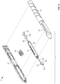
- FIGS. 1-3 show an ophthalmic surgical instrument 1 that has a housing 10, an elongated shaft in the form of a needle 20 having a distal end 21, an opening 22 in a side wall thereof, and a snare 30 formed by a wire, for severing lenticular tissue.
- the elongated shaft 20 is dimensioned for passage through a corneal incision and has a proximal end portion 23 that may be integrally formed with or attached to the housing 10 or to a slider cartridge 40 shown in FIG. 2 .
- the snare 30 of the ophthalmic surgical instrument 1 is movable relative to and within the elongated shaft 20 via an actuation mechanism formed by slider cartridge 40 and slider button 45, which rests in channel 41 of slider cartridge 40.
- Slider cartridge 40 is accessible through an opening 15 in housing 10.
- a first end of snare 30 is connected to slider button 45, as shown in FIG. 4 , and the second end of snare 30 is fixed within the housing, so that moving slider button 45 along channel 41 expands and retracts looped segment 33 formed by snare 30. Retracting looped segment 33 by sliding button 45 away from distal end 22 allows snare 30 to bisect a lens that is disposed within loop 33 during surgery.
- the snare 30 is fabricated from a pliable, metal material, such as, for example, nickel-titanium or any other suitable superelastic material.
- the snare may be fabricated from any suitable ductile material.
- a light-conducting tube 50 Surrounding the snare 30 is a light-conducting tube 50, which extends at least partially around the looped segment 33. In the embodiment of FIGS. 1-4 , tube 50 terminates at a distal end 51, which is located at a bottom of the looped segment 33. As shown in FIG. 4 , tube 50 extends around the top portion of looped segment 33, enters the elongated shaft 20 with snare 30, extends through slider cartridge 40, and connects to a light source 60, which is disposed in housing 10.
- Light source 60 can be connected to power source 70, such as a battery, also disposed in housing 10, so that the ophthalmic surgical instrument 1 is completely portable and wireless.
- the light source 60 may be a light-emitting diode (LED), a compact fluorescent lamp, an incandescent light bulb, or any other suitable source of light.
- the light source 60 is in communication with the tube 50 so that the light from the light source is emitted out of the tube and out of distal end 51.
- Tube 50 is also preferably made of a flexible, translucent material such as polyurethane, so that the light is emitted along the length of the tube 50 and is visible along the entire length. In this embodiment, the light would appear as a bright spot at the distal end 51 exit as well.
- Tube 50 is made of an opaque material, or is covered by an opaque coating or covering, so that only the light exiting out of distal end 51 is visible.
- tube 50 can be covered by a metal covering.
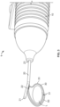
- the elongated shaft 20 is inserted through a corneal incision and a capsulorhexis to position the distal end portion 21 around a surface of the lens L.
- the surgeon is able to use the light emitted from the tube 50 to appropriately position the snare 30 relative to the lens "L.”
- the looped segment 33 With the looped segment 33 in the selected position, which is verified using the light transmitted out of the bottom 51 of tube 50, the looped segment 33 is transitioned from the dilated configuration to the contracted configuration, thereby severing the lens "L.”
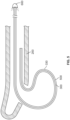
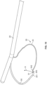
- FIG. 5 shows an alternative embodiment of the invention, where device 100 has an elongated shaft 200 with an opening 220 through which a snare 300 formed by wire extends in a looped segment 330.
- Snare 300 is completely encased in a light-conducting tube 500, which is connected to a light source 600, in the same manner as described above with respect to FIGS. 1-4 .
- Tube 500 is transparent or translucent, so that the light from light source 600 is visible along the entire extent of the snare.
- Tube 500 is thin enough so that snare 300 surrounded by tube 500 is still able to bisect a lens when snare 300 is moved to the retracted position in the manner described above with respect to FIGS. 1-4 (using the same slider mechanism as described above).
- FIG. 6 shows another alternative embodiment, where light source 660 is located outside the housing 10 of ophthalmic surgical instrument 1. Snare 350 surrounded by tube 550 extends entirely through the housing and out to remote light source 660, which can be located on a remote device or by itself. This embodiment allows for the use of a larger, more powerful light source and a larger power supply than may be available to place inside housing 10.
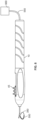
- FIGS. 7 and 8 An alternative embodiment of the invention is shown in FIGS. 7 and 8 .
- a light-conducting element in the form of a solid filament 5500 extends parallel to snare 3000, and terminates at a mid-point of looped segment 3300 of snare 3000.
- a coiled cover 4000 surrounds the snare 3000 and filament 5500 to keep the two components together.
- Cover 4000 can be formed of metal wire or any other suitable material, such as a polymer, or any other suitable mixture of materials.
- the light from filament 5500 exits out of end 5510 and forms a bright spot behind the lens during surgery, in the same manner as explained above with respect to FIGS 1-4 .
- Filament 5500 is connected to a light source that is disposed in the housing 10 or in a location remote from housing 10 in the same manner as disclosed with the embodiments of FIGS. 1-6 .
- FIG. 9 shows a further embodiment of the invention, which is identical to the embodiment of FIGS. 7 and 8 , using the instrument of FIGS. 1-6 , except that in this situation, cover 8000 is in the form of a woven material, typically a metallic tape or thread, but any other suitable materials could be used as well. It is also envisioned that a cover could be constructed of a solid tube or a molded material that covers both the snare 3000 and the filament 5500.
- FIG. 10 A further embodiment is shown in FIG. 10 , here the ophthalmic surgical instrument 1 is identical to the instrument shown in FIGS. 1-4 , except that here, snare 30 is bent in two places in opposite directions at a bottom of looped portion 33, in the form of a Z- or S-shape, so that an intermediate section 340 between bends 341 and 342 extends upward toward elongated shaft 20, obliquely to the extent of looped portion 33.
- Tube 50 terminates in the intermediate section 340, so that distal end 51 is aimed toward elongated shaft 20.
Landscapes
- Health & Medical Sciences (AREA)
- Ophthalmology & Optometry (AREA)
- Heart & Thoracic Surgery (AREA)
- Surgery (AREA)
- Engineering & Computer Science (AREA)
- Biomedical Technology (AREA)
- Nuclear Medicine, Radiotherapy & Molecular Imaging (AREA)
- Vascular Medicine (AREA)
- Life Sciences & Earth Sciences (AREA)
- Animal Behavior & Ethology (AREA)
- General Health & Medical Sciences (AREA)
- Public Health (AREA)
- Veterinary Medicine (AREA)
- Surgical Instruments (AREA)
Claims (14)
- Ein ophthalmisches chirurgisches Instrument (1) zum Durchtrennen einer Linse (L) eines Auges, umfassend:einen länglichen Schaft (20, 200) mit einem distalen Endabschnitt (21);einen Draht (30, 300, 350) sich erstreckend entlang des länglichen Schafts (20, 200) und mit einem Schleifen-Segment (33, 330) angeordnet angrenzend an den distalen Endabschnitt (21) und konfiguriert sich zwischen einer zusammengezogenen Konfiguration und einer erweiterten Konfiguration zu bewegen, in der das Schleifen-Segment (33, 330) einen Durchmesser annimmt, der dem Durchmesser und der Form einer Linse (L) eines Auges nahekommt, das Schleifen-Segment (33, 300) weist einen unteren Abschnitt auf der so konfiguriert ist, dass ein unterer Teil der Linse (L) eingezogen und durchtrennt wird, wenn es sich in Richtung der zusammengezogenen Konfiguration bewegt, wenn das Schleifen-Segment (33, 330) um die Linse (L) gelegt wird,ein lichtleitendes Element (50, 500, 550) sich erstreckend entlang mindestens eines Teils der Länge des Schleifen-Segments (33, 330), undeine Lichtquelle (60, 600, 660) in Verbindung mit dem Lichtleitelement (50, 500, 550), so dass Licht von der Lichtquelle (60, 6 00, 660) durch das lichtleitende Element (50, 500, 550) wandert und mindestens einen Teil der Länge des Schleifen-Segments (33, 330) beleuchtet,dadurch gekennzeichnet, dass das lichtleitende Element (50, 500, 550) ein Rohr ist, das den Draht (30, 300, 350) umgibt.
- Ein ophthalmisches chirurgisches Instrument (1) zum Durchtrennen einer Linse (L) eines Auges, umfassend:einen länglichen Schaft (20, 200) mit einem distalen Endabschnitt (21);einen Draht (3000) sich erstreckend entlang des länglichen Schafts (20, 200) und mit einem Schleifen-Segment (3300) angeordnet angrenzend an den distalen Endabschnitt (21) und konfiguriert sich zwischen einer zusammengezogenen Konfiguration und einer erweiterten Konfiguration zu bewegen, in der das Schleifen-Segment (3300) einen Durchmesser annimmt, der dem Durchmesser und der Form einer Linse (L) eines Auges nahekommt, das Schleifen-Segment (3300) weist einen unteren Abschnitt auf der so konfiguriert ist, dass ein unterer Teil der Linse (L) eingezogen und durchtrennt wird, wenn es sich in Richtung der zusammengezogenen Konfiguration bewegt, wenn das Schleifen-Segment (3300) um die Linse (L) gelegt wird,ein lichtleitendes Element (5500) sich erstreckend entlang mindestens eines Teils der Länge des Schleifen-Segments (3300), undeine Lichtquelle (60, 600, 660) in Verbindung mit dem lichtleitenden Element (5500), so dass Licht von der Lichtquelle (60, 600, 660) durch das lichtleitende Element (5500) wandert und mindestens einen Teil der Länge des Schleifen-Segments (3300) beleuchtet,dadurch gekennzeichnet, dass das lichtleitende Element (5500) ein massives Filament ist, das sich neben dem Draht (3000) erstreckt.
- Das ophthalmische chirurgische Instrument gemäß Anspruch 1 oder 2, wobei das lichtleitende Element (50, 500, 550, 5500) transluzent ist.
- Das ophthalmische chirurgische Instrument gemäß einem der Ansprüche 1 bis 3, wobei das lichtleitende Element (50, 500, 550, 5500) am unteren Teil des Schleifen-Segments (33, 330, 3300) endet und Licht von der Lichtquelle (60, 600, 660) am unteren Teil des Schleifensegments (33, 330, 3300) aus dem lichtleitenden Element (50, 500, 550, 5500) austritt.
- Das ophthalmische chirurgische Instrument gemäß einem der Ansprüche 1 bis 4, wobei das lichtleitende Element (50, 500, 550, 5500) aus Polyurethan besteht.
- Das ophthalmische chirurgische Instrument gemäß Anspruch 4 oder 5, wobei das lichtleitende Element (50, 500, 550, 5500) opak ist oder mit einer opaken Beschichtung oder Abdeckung (4000, 8000) bedeckt ist, so dass Licht von der Lichtquelle (60, 600, 660) nur an einem Ende des lichtleitenden Elements (50, 500, 550, 5500) sichtbar ist.
- Das ophthalmologische chirurgische Instrument gemäß einem der Ansprüche 1 bis 6, wobei der Draht (30, 300, 350, 3000) aus Nitinol besteht.
- Das ophthalmische chirurgische Instrument gemäß einem der Ansprüche 1 bis 7, wobei sich das lichtleitende Element (50, 500, 550, 5500) durch den länglichen Schaft (20, 200) erstreckt.
- Das ophthalmische chirurgische Instrument gemäß einem der Ansprüche 1 bis 8, ferner umfassend ein Gehäuse (10) verbunden mit dem länglichen Schaft (20, 200), das Gehäuse (10) umfasst einen Aktuator (40), der mit dem Draht (30, 300, 350, 3000) verbunden ist und so konfiguriert ist, dass er den Draht (30, 300, 350, 3000) zwischen der zusammengezogenen und der ausgedehnten Konfiguration bewegt.
- Das ophthalmologische chirurgische Instrument gemäß einem der Ansprüche 1 bis 9, wobei die Lichtquelle (60, 600, 660) eine Leuchtdiode (LED) ist.
- Das ophthalmische chirurgische Instrument gemäß einem der Ansprüche 6 bis 10, wobei das lichtleitende Element (50, 500, 550, 5500) und Draht (30, 300, 350, 3000) von einer Ummantelung (4000, 8000) bedeckt sind, die gewebt oder gewickelt ist.
- Das ophthalmische chirurgische Instrument gemäß Anspruch 11, wobei die Abdeckung (4000, 8000) aus Metall besteht.
- Das ophthalmische chirurgische Instrument gemäß einem der Ansprüche 1 bis 12, wobei der Draht (30, 300, 350, 3000) an zwei entgegengesetzten Stellen an einem ungefähren Mittelpunkt des Schleifen-Segments (33, 330, 3300) gebogen ist, um einen Zwischenabschnitt (340) zu erzeugen, der nicht parallel zu Schleifen-Segment (33, 330, 3300) verläuft.
- Das ophthalmische chirurgische Instrument gemäß Anspruch 13, wobei das lichtleitende Element (50, 500, 550, 5500) an dem Zwischenabschnitt (340) des Schleifen-Segments (33, 330, 3300) endet, so dass ein distales Ende des lichtleitenden Elements (50, 500, 550, 5500) dem länglichen Schaft (20, 200) zugewandt ist.
Applications Claiming Priority (1)
| Application Number | Priority Date | Filing Date | Title |
|---|---|---|---|
| US17/590,081 US11432960B1 (en) | 2022-02-01 | 2022-02-01 | Ophthalmic medical instrument with illuminated snare |
Publications (3)
| Publication Number | Publication Date |
|---|---|
| EP4218693A1 EP4218693A1 (de) | 2023-08-02 |
| EP4218693C0 EP4218693C0 (de) | 2024-12-11 |
| EP4218693B1 true EP4218693B1 (de) | 2024-12-11 |
Family
ID=83149723
Family Applications (1)
| Application Number | Title | Priority Date | Filing Date |
|---|---|---|---|
| EP23154125.1A Active EP4218693B1 (de) | 2022-02-01 | 2023-01-31 | Ophthalmisches medizinisches instrument mit beleuchteter schlinge |
Country Status (5)
| Country | Link |
|---|---|
| US (1) | US11432960B1 (de) |
| EP (1) | EP4218693B1 (de) |
| JP (1) | JP2023112679A (de) |
| AU (1) | AU2023200282A1 (de) |
| CA (1) | CA3188074A1 (de) |
Families Citing this family (6)
| Publication number | Priority date | Publication date | Assignee | Title |
|---|---|---|---|---|
| JP2022094240A (ja) * | 2020-12-14 | 2022-06-24 | 株式会社三洋物産 | 遊技機 |
| JP2022094241A (ja) * | 2020-12-14 | 2022-06-24 | 株式会社三洋物産 | 遊技機 |
| JP2022094242A (ja) * | 2020-12-14 | 2022-06-24 | 株式会社三洋物産 | 遊技機 |
| JP2022094239A (ja) * | 2020-12-14 | 2022-06-24 | 株式会社三洋物産 | 遊技機 |
| JP2022094238A (ja) * | 2020-12-14 | 2022-06-24 | 株式会社三洋物産 | 遊技機 |
| JP7367715B2 (ja) * | 2021-03-02 | 2023-10-24 | 株式会社三洋物産 | 遊技機 |
Family Cites Families (10)
| Publication number | Priority date | Publication date | Assignee | Title |
|---|---|---|---|---|
| EP2291697A1 (de) * | 2008-06-19 | 2011-03-09 | Corning Cable Systems LLC | Glasfaserkabel und anordnungen sowie ihre leistung |
| AU2011289611A1 (en) * | 2010-08-09 | 2013-02-07 | Alcon Research, Ltd. | Illuminated surgical instrument |
| WO2013067007A1 (en) * | 2011-10-31 | 2013-05-10 | Boston Scientific Scimed, Inc. | Rotatable medical device |
| WO2014066777A1 (en) | 2012-10-25 | 2014-05-01 | The Regents Of The University Of Colorado, A Body Corporate | Adjustable loop fiber optic illumination device for surgery |
| CN107072814B (zh) * | 2014-09-17 | 2021-01-26 | 卡尔蔡司白内障医疗技术公司 | 用于取出晶状体组织的装置和方法 |
| DE102016118203A1 (de) | 2016-05-10 | 2017-11-16 | Claas Selbstfahrende Erntemaschinen Gmbh | Zugmaschinen-Geräte-Kombination mit Fahrerassistenzsystem |
| EP3629945A4 (de) * | 2017-05-25 | 2021-03-03 | Terumo Corporation | Haftende verschlusssysteme |
| US10292862B1 (en) | 2018-05-03 | 2019-05-21 | Richard Mackool | Ophthalmic surgical instruments and methods of use thereof |
| US11007079B1 (en) | 2019-12-02 | 2021-05-18 | Richard Mackool | Ophthalmic surgical instruments and snares thereof |
| US10485700B1 (en) * | 2019-06-24 | 2019-11-26 | Richard Mackool | Ophthalmic surgical instruments and snares thereof |
-
2022
- 2022-02-01 US US17/590,081 patent/US11432960B1/en active Active
-
2023
- 2023-01-19 AU AU2023200282A patent/AU2023200282A1/en active Pending
- 2023-01-27 JP JP2023010767A patent/JP2023112679A/ja active Pending
- 2023-01-30 CA CA3188074A patent/CA3188074A1/en active Pending
- 2023-01-31 EP EP23154125.1A patent/EP4218693B1/de active Active
Also Published As
| Publication number | Publication date |
|---|---|
| US11432960B1 (en) | 2022-09-06 |
| AU2023200282A1 (en) | 2023-08-17 |
| EP4218693C0 (de) | 2024-12-11 |
| CA3188074A1 (en) | 2023-08-01 |
| JP2023112679A (ja) | 2023-08-14 |
| EP4218693A1 (de) | 2023-08-02 |
Similar Documents
| Publication | Publication Date | Title |
|---|---|---|
| EP4218693B1 (de) | Ophthalmisches medizinisches instrument mit beleuchteter schlinge | |
| ES2383523T3 (es) | Sistema de control para accesorio endoscópico externo | |
| US5695492A (en) | Lamellar illumination apparatus for eye surgery | |
| US5582608A (en) | Lamellar illumination apparatus for eye surgery | |
| US20020107579A1 (en) | Nasolacrimal duct tube used for lacrimal duct reformation operation, and nasolacrimal duct tube instrument | |
| US3903892A (en) | Forceps means for removing cellular tissue from the body cavities | |
| US20050135776A1 (en) | Surgical cutting tool | |
| US5967971A (en) | Surgical instrument | |
| JP3854946B2 (ja) | 内視鏡 | |
| US20110106113A1 (en) | System and method for hernia mesh fixation | |
| WO2015164881A1 (en) | Illuminating speculum | |
| WO2003075979A2 (en) | Chemiluminescently illuminated medical appliances | |
| JP2023112679A5 (de) | ||
| JP2016526998A (ja) | 縫合糸の経骨挿入用完全機器 | |
| WO2004002337A1 (en) | Surgical cutting tool | |
| CN115702773A (zh) | 一种内窥镜的镜管组件及内窥镜 | |
| JP2001327525A (ja) | 涙道再形成手術に用いる鼻涙管チューブおよび鼻涙管チューブ器具 | |
| CN116369829B (zh) | 内窥镜、成像系统及内窥镜控制方式 | |
| EP0568774A1 (de) | Endoskopische Anastomosevorrichtung für das Einsetzen eines Ringes | |
| US9795302B2 (en) | Tissue illumination system, device, and method | |
| KR102038073B1 (ko) | 광파이버 튜브 제조방법 및 복강경 수술용 조명유닛 | |
| CN121443202A (zh) | 用于使医疗装置铰接和/或后屈的装置、系统和方法 | |
| US11007079B1 (en) | Ophthalmic surgical instruments and snares thereof | |
| JP3998981B2 (ja) | 内視鏡用鉗子 | |
| JP2003079573A (ja) | 耳鏡、耳清掃具及び耳清掃具セット |
Legal Events
| Date | Code | Title | Description |
|---|---|---|---|
| PUAI | Public reference made under article 153(3) epc to a published international application that has entered the european phase |
Free format text: ORIGINAL CODE: 0009012 |
|
| STAA | Information on the status of an ep patent application or granted ep patent |
Free format text: STATUS: THE APPLICATION HAS BEEN PUBLISHED |
|
| AK | Designated contracting states |
Kind code of ref document: A1 Designated state(s): AL AT BE BG CH CY CZ DE DK EE ES FI FR GB GR HR HU IE IS IT LI LT LU LV MC ME MK MT NL NO PL PT RO RS SE SI SK SM TR |
|
| STAA | Information on the status of an ep patent application or granted ep patent |
Free format text: STATUS: REQUEST FOR EXAMINATION WAS MADE |
|
| 17P | Request for examination filed |
Effective date: 20231127 |
|
| RBV | Designated contracting states (corrected) |
Designated state(s): AL AT BE BG CH CY CZ DE DK EE ES FI FR GB GR HR HU IE IS IT LI LT LU LV MC ME MK MT NL NO PL PT RO RS SE SI SK SM TR |
|
| GRAP | Despatch of communication of intention to grant a patent |
Free format text: ORIGINAL CODE: EPIDOSNIGR1 |
|
| STAA | Information on the status of an ep patent application or granted ep patent |
Free format text: STATUS: GRANT OF PATENT IS INTENDED |
|
| INTG | Intention to grant announced |
Effective date: 20240704 |
|
| RIN1 | Information on inventor provided before grant (corrected) |
Inventor name: MACKOOL, RICHARD JONATHAN Inventor name: JONES, EVAN RITTENHOUSE Inventor name: SMITH, CHRISTOPHER DEAN Inventor name: MACKOOL, RICHARD JAMES |
|
| GRAS | Grant fee paid |
Free format text: ORIGINAL CODE: EPIDOSNIGR3 |
|
| GRAA | (expected) grant |
Free format text: ORIGINAL CODE: 0009210 |
|
| STAA | Information on the status of an ep patent application or granted ep patent |
Free format text: STATUS: THE PATENT HAS BEEN GRANTED |
|
| AK | Designated contracting states |
Kind code of ref document: B1 Designated state(s): AL AT BE BG CH CY CZ DE DK EE ES FI FR GB GR HR HU IE IS IT LI LT LU LV MC ME MK MT NL NO PL PT RO RS SE SI SK SM TR |
|
| REG | Reference to a national code |
Ref country code: GB Ref legal event code: FG4D |
|
| REG | Reference to a national code |
Ref country code: CH Ref legal event code: EP |
|
| REG | Reference to a national code |
Ref country code: IE Ref legal event code: FG4D |
|
| REG | Reference to a national code |
Ref country code: DE Ref legal event code: R096 Ref document number: 602023001279 Country of ref document: DE |
|
| U01 | Request for unitary effect filed |
Effective date: 20250106 |
|
| U07 | Unitary effect registered |
Designated state(s): AT BE BG DE DK EE FI FR IT LT LU LV MT NL PT RO SE SI Effective date: 20250115 |
|
| U20 | Renewal fee for the european patent with unitary effect paid |
Year of fee payment: 3 Effective date: 20250221 |
|
| PG25 | Lapsed in a contracting state [announced via postgrant information from national office to epo] |
Ref country code: HR Free format text: LAPSE BECAUSE OF FAILURE TO SUBMIT A TRANSLATION OF THE DESCRIPTION OR TO PAY THE FEE WITHIN THE PRESCRIBED TIME-LIMIT Effective date: 20241211 |
|
| PG25 | Lapsed in a contracting state [announced via postgrant information from national office to epo] |
Ref country code: ES Free format text: LAPSE BECAUSE OF FAILURE TO SUBMIT A TRANSLATION OF THE DESCRIPTION OR TO PAY THE FEE WITHIN THE PRESCRIBED TIME-LIMIT Effective date: 20241211 |
|
| PG25 | Lapsed in a contracting state [announced via postgrant information from national office to epo] |
Ref country code: NO Free format text: LAPSE BECAUSE OF FAILURE TO SUBMIT A TRANSLATION OF THE DESCRIPTION OR TO PAY THE FEE WITHIN THE PRESCRIBED TIME-LIMIT Effective date: 20250311 |
|
| PG25 | Lapsed in a contracting state [announced via postgrant information from national office to epo] |
Ref country code: GR Free format text: LAPSE BECAUSE OF FAILURE TO SUBMIT A TRANSLATION OF THE DESCRIPTION OR TO PAY THE FEE WITHIN THE PRESCRIBED TIME-LIMIT Effective date: 20250312 |
|
| PG25 | Lapsed in a contracting state [announced via postgrant information from national office to epo] |
Ref country code: RS Free format text: LAPSE BECAUSE OF FAILURE TO SUBMIT A TRANSLATION OF THE DESCRIPTION OR TO PAY THE FEE WITHIN THE PRESCRIBED TIME-LIMIT Effective date: 20250311 |
|
| PG25 | Lapsed in a contracting state [announced via postgrant information from national office to epo] |
Ref country code: SM Free format text: LAPSE BECAUSE OF FAILURE TO SUBMIT A TRANSLATION OF THE DESCRIPTION OR TO PAY THE FEE WITHIN THE PRESCRIBED TIME-LIMIT Effective date: 20241211 |
|
| PG25 | Lapsed in a contracting state [announced via postgrant information from national office to epo] |
Ref country code: PL Free format text: LAPSE BECAUSE OF FAILURE TO SUBMIT A TRANSLATION OF THE DESCRIPTION OR TO PAY THE FEE WITHIN THE PRESCRIBED TIME-LIMIT Effective date: 20241211 |
|
| PG25 | Lapsed in a contracting state [announced via postgrant information from national office to epo] |
Ref country code: IS Free format text: LAPSE BECAUSE OF FAILURE TO SUBMIT A TRANSLATION OF THE DESCRIPTION OR TO PAY THE FEE WITHIN THE PRESCRIBED TIME-LIMIT Effective date: 20250411 |
|
| PG25 | Lapsed in a contracting state [announced via postgrant information from national office to epo] |
Ref country code: SK Free format text: LAPSE BECAUSE OF FAILURE TO SUBMIT A TRANSLATION OF THE DESCRIPTION OR TO PAY THE FEE WITHIN THE PRESCRIBED TIME-LIMIT Effective date: 20241211 |
|
| PG25 | Lapsed in a contracting state [announced via postgrant information from national office to epo] |
Ref country code: CZ Free format text: LAPSE BECAUSE OF FAILURE TO SUBMIT A TRANSLATION OF THE DESCRIPTION OR TO PAY THE FEE WITHIN THE PRESCRIBED TIME-LIMIT Effective date: 20241211 |
|
| PG25 | Lapsed in a contracting state [announced via postgrant information from national office to epo] |
Ref country code: MC Free format text: LAPSE BECAUSE OF FAILURE TO SUBMIT A TRANSLATION OF THE DESCRIPTION OR TO PAY THE FEE WITHIN THE PRESCRIBED TIME-LIMIT Effective date: 20241211 |
|
| PLBE | No opposition filed within time limit |
Free format text: ORIGINAL CODE: 0009261 |
|
| STAA | Information on the status of an ep patent application or granted ep patent |
Free format text: STATUS: NO OPPOSITION FILED WITHIN TIME LIMIT |
|
| 26N | No opposition filed |
Effective date: 20250912 |
|
| PG25 | Lapsed in a contracting state [announced via postgrant information from national office to epo] |
Ref country code: IE Free format text: LAPSE BECAUSE OF NON-PAYMENT OF DUE FEES Effective date: 20250131 |
|
| U20 | Renewal fee for the european patent with unitary effect paid |
Year of fee payment: 4 Effective date: 20260129 |