EP4216258A1 - Components for a chemical mechanical polishing tool - Google Patents
Components for a chemical mechanical polishing tool Download PDFInfo
- Publication number
- EP4216258A1 EP4216258A1 EP23154241.6A EP23154241A EP4216258A1 EP 4216258 A1 EP4216258 A1 EP 4216258A1 EP 23154241 A EP23154241 A EP 23154241A EP 4216258 A1 EP4216258 A1 EP 4216258A1
- Authority
- EP
- European Patent Office
- Prior art keywords
- component
- hydrophobic layer
- polishing
- fluid
- cmp tool
- Prior art date
- Legal status (The legal status is an assumption and is not a legal conclusion. Google has not performed a legal analysis and makes no representation as to the accuracy of the status listed.)
- Withdrawn
Links
Images



Classifications
-
- B—PERFORMING OPERATIONS; TRANSPORTING
- B24—GRINDING; POLISHING
- B24B—MACHINES, DEVICES, OR PROCESSES FOR GRINDING OR POLISHING; DRESSING OR CONDITIONING OF ABRADING SURFACES; FEEDING OF GRINDING, POLISHING, OR LAPPING AGENTS
- B24B53/00—Devices or means for dressing or conditioning abrasive surfaces
- B24B53/017—Devices or means for dressing, cleaning or otherwise conditioning lapping tools
-
- B—PERFORMING OPERATIONS; TRANSPORTING
- B24—GRINDING; POLISHING
- B24B—MACHINES, DEVICES, OR PROCESSES FOR GRINDING OR POLISHING; DRESSING OR CONDITIONING OF ABRADING SURFACES; FEEDING OF GRINDING, POLISHING, OR LAPPING AGENTS
- B24B37/00—Lapping machines or devices; Accessories
- B24B37/27—Work carriers
- B24B37/30—Work carriers for single side lapping of plane surfaces
- B24B37/32—Retaining rings
-
- B—PERFORMING OPERATIONS; TRANSPORTING
- B24—GRINDING; POLISHING
- B24B—MACHINES, DEVICES, OR PROCESSES FOR GRINDING OR POLISHING; DRESSING OR CONDITIONING OF ABRADING SURFACES; FEEDING OF GRINDING, POLISHING, OR LAPPING AGENTS
- B24B37/00—Lapping machines or devices; Accessories
- B24B37/34—Accessories
-
- B—PERFORMING OPERATIONS; TRANSPORTING
- B24—GRINDING; POLISHING
- B24B—MACHINES, DEVICES, OR PROCESSES FOR GRINDING OR POLISHING; DRESSING OR CONDITIONING OF ABRADING SURFACES; FEEDING OF GRINDING, POLISHING, OR LAPPING AGENTS
- B24B57/00—Devices for feeding, applying, grading or recovering grinding, polishing or lapping agents
- B24B57/02—Devices for feeding, applying, grading or recovering grinding, polishing or lapping agents for feeding of fluid, sprayed, pulverised, or liquefied grinding, polishing or lapping agents
-
- H—ELECTRICITY
- H10—SEMICONDUCTOR DEVICES; ELECTRIC SOLID-STATE DEVICES NOT OTHERWISE PROVIDED FOR
- H10P—GENERIC PROCESSES OR APPARATUS FOR THE MANUFACTURE OR TREATMENT OF DEVICES COVERED BY CLASS H10
- H10P52/00—Grinding, lapping or polishing of wafers, substrates or parts of devices
-
- H—ELECTRICITY
- H10—SEMICONDUCTOR DEVICES; ELECTRIC SOLID-STATE DEVICES NOT OTHERWISE PROVIDED FOR
- H10P—GENERIC PROCESSES OR APPARATUS FOR THE MANUFACTURE OR TREATMENT OF DEVICES COVERED BY CLASS H10
- H10P52/00—Grinding, lapping or polishing of wafers, substrates or parts of devices
- H10P52/40—Chemomechanical polishing [CMP]
- H10P52/402—Chemomechanical polishing [CMP] of semiconductor materials
Definitions
- Embodiments described herein generally relate to a component for use in a chemical mechanical polishing tool, wherein the component includes a hydrophobic layer disposed on a surface of the component.
- the present disclosure relates generally to chemical mechanical polishing of substrates, and more particularly to components of a chemical mechanical polishing apparatus.
- Integrated circuits are typically formed on substrates, such as silicon wafers, by sequential deposition of conductive, semiconductive, or insulative layers. After each layer is deposited, the layer is etched to create circuitry features. As a series of layers are sequentially deposited and etched, the outer or uppermost surface of the substrate, i.e., the exposed surface of the substrate, becomes increasingly non-planar. This non-planar outer surface presents a problem for the integrated circuit manufacturer. Therefore, there is a need to periodically planarize the substrate surface to provide a flat surface.
- CMP Chemical mechanical polishing
- CMP typically includes the substrate mounted on a carrier or polishing head. The exposed surface of the substrate is then placed against a rotating polishing pad.
- the carrier head provides a controllable load, i.e., pressure, on the substrate to push the substrate against the polishing pad.
- the carrier head may rotate to provide additional motion between the substrate and polishing surface.
- a polishing slurry including an abrasive and at least one chemically-reactive agent, may be supplied to the polishing pad to provide an abrasive chemical solution at the interface between the pad and the substrate.
- the polishing slurry may also contact and adhere to components of the CMP tool. Over time, the polishing slurry can rub over the surface of the components thereby dislodging component particles. Some of these particles may fall on to the polishing pad, which may result in scratching of the substrate. Scratches may result in substrate defects, which lead to performance degradation while polishing of the finished device. Additionally, the slurry particles may begin to erode the components of the CMP tool that are contacted by the slurry. Thus, the life spans of those parts are decreased, and the parts need to be replaced more readily.
- a component for a CMP tool includes a body having a surface that will be exposed to a polishing fluid when the CMP tool is polishing a substrate and a hydrophobic layer disposed on the surface of the body.
- the hydrophobic layer having a fluid contact angle of at least 90°.
- a component for a CMP tool in another embodiment, includes a ring shaped body and a hydrophobic layer.
- the ring shaped body is defined by a lower side and an upper side.
- the lower side includes a lower edge, an upper edge, an outer surface having an outer diameter, an inner surface having an inner diameter, and a first hydrophobic layer.
- the upper edge extends towards the upper side.
- the inner diameter is less than the outer diameter.
- the outer surface and the inner surface are concentric about a central axis.
- the first hydrophobic layer is disposed on the inner surface of the lower side.
- the first hydrophobic layer has a contact angle of at least 90° when a fluid contacts a portion of the inner surface of the lower side.
- the upper side includes a lower edge, an upper edge, and outer surface having an outer diameter, an inner surface having an inner diameter, and a second hydrophobic layer.
- the lower edge is integral with the upper edge of the lower side.
- the upper edge of the upper side extends radially inward from the inner edge of the upper surface in an upwards direction.
- the outer diameter of the upper side is less than the outer diameter of the lower side.
- the inner diameter of the upper side is less than the inner diameter of the lower side.
- the second hydrophobic layer has a contact angle of at least 90° when a fluid contacts a portion of the inner surface of the upper side.
- a component in a CMP tool includes a disk shaped body and a hydrophobic layer deposited on the disk shaped body.
- the disk shaped body has a top surface, a bottom surface, an outer wall, an inner wall, and a ledge.
- the bottom surface is substantially parallel to the top surface.
- the outer wall is perpendicular to the bottom surface.
- the outer wall includes an outer diameter, a first end, and a second end.
- the first end of the outer wall is integral with the bottom surface.
- the second end is opposite the first end.
- the inner wall is perpendicular to the top surface.
- the inner wall includes an inner diameter, a first end, and a second end. The inner diameter is less than the outer diameter.
- the second end of the inner wall is integral with the top surface.
- the ledge is defined by the outer wall and the inner wall.
- the ledge is perpendicular to the outer wall and the inner wall.
- the ledge has a first end and a second end.
- the first end of the ledge is integral to the second end of the outer wall.
- the second end of the ledge is radially inward from the first end of the ledge.
- the second end of the ledge is integrally connected with the first end of the other wall.
- the second end of the outer wall is radially inward from the first end of the outer wall, towards the top surface.
- the hydrophobic layer has a contact angle of at least 90° when a fluid contacts a portion of disk shaped body.
- Embodiments of the present disclosure are described herein in accordance with components of a CMP tool.
- FIG. 1 depicts a conventional chemical mechanical polishing (CMP) tool 100 for polishing a substrate (not shown).
- the CMP tool 100 may include a base 101.
- the base 101 includes a carriage 102 and a plurality of stations 108.
- the carriage 102 is centrally disposed on the base 101.
- the carriage 102 may include a plurality of arms 110, each supporting a polishing head 112.
- the arms 110 extend from the carriage 102 out over each station 108.
- the polishing heads 112 are generally supported above the stations 108.
- the polishing heads 112 include a recess (not shown) configured to retain a substrate during polishing.
- the stations 108 may be, for example, a transfer station 113 or a polishing station 111.
- Two arms 110 depicted in Figure 1 are shown in phantom such that the transfer station 113 and polishing station 111 of the first station 108 may be shown.
- the carriage 102 is indexable such that the polishing head 112 may be moved between the polishing station 111 and the transfer station 113.
- Conditioning devices 134 may be disposed on the base 101 adjacent to each of the polishing stations 111.
- the conditioning devices 134 may be used to periodically condition the polishing surface of the polishing stations 111 to maintain uniform polishing results.
- Each polishing station 111 has a fluid delivery arm 109.
- the fluid delivery arm 109 delivers a polishing fluid to the polishing surface of the polishing station 111 so that a substrate may be polished.
- the polishing fluid may come into contact with components of the CMP tool. If a slurry is used as the polishing fluid, the slurry particles adhere to the different components of the CMP tool. Over time, the polishing slurry can rub over the surface of a component thereby dislodging component particles. Some of these particles may fall onto the polishing surface, and potentially become a source of scratches on the substrate being polished. These scratches may result in poor device performance and high defects. Additionally, the slurry particles may begin to erode those components of the CMP tool. Thus, there is a need to limit the contact between the fluid and the components of the CMP tool such that erosion of the components is delayed and the life span is extended.
- Figures 2A-2C compare CMP tool components with and without a hydrophobic layer applied to an exterior of the CMP tool component.
- Figure 2A illustrates a portion of a CMP tool component that does not have a hydrophobic layer on an exterior surface.
- the angle at which a fluid contacts the surface of the CMP tool component is referred to as the contact angle.
- the contact angle is determined by the resultant between adhesive and cohesive surfaces.
- the contact angle 206 between the fluid and the CMP tool component is about 60°.
- a surface which has a high degree of wetting and a contact angle less than 90° is referred to as a hydrophilic surface.
- the measure of wetting of a surface is inversely related to the contact angle.
- the low contact angle between the fluid and the CMP tool components illustrates that the CMP tool has a high degree of wetting.
- a high degree of wetting results in more slurry particles adhering to an exterior surface of the CMP tool component. More slurry contact with CMP tool component increases the likelihood of dislodging some surface particles from the CMP tool component. Such dislodged component particles will fall onto the polishing surface of the polishing station and scratch the substrate.
- the CMP tool components illustrated in Figures 2B-2C have a hydrophobic layer disposed an exterior surface of the component.
- the hydrophobic layer may be in the form of monomolecular layers (adsorbed orientated layers about one molecule thick) or lacquer films by treating a material with solutions, emulsions, or less frequently, vapors of hydrophobic agents, which are substances that interact weakly with water but attach themselves to a surface.
- the hydrophobic layer may be deposited on a CMP tool component using a plasma treatment performed in a plasma chamber.
- the plasma treatment utilizes a low-pressure plasma system, which is inexpensive and consumes minimal gas.
- monomers are introduced into the chamber and react chemically among each other to form polymers.
- the monomers that are introduced into the chamber may be, for example, hexamethyldisiloxane, heptadecafluorodecyltrimethoxysilane, poly(tetrafluoroethylene), poly(propylene), octadecyldimethylchlorosilane, octadecyltrichlorosilane, tris(trimethylsiloxy)silylethyl-dimethylchlorosilane, octyldimethylchlorosilane, or dimethyldichlorosilane.
- the contact angle between the fluid and the surface may be measured using different techniques.
- one technique includes placing a sample, in this case a component of a CMP tool, on a flat surface. A constant volume of water or slurry solution is then dispersed onto the component with a pipette. While the droplets are on the hydrophobic layer disposed on the exterior of the component, a picture is taken of the droplet disposed on the layer. The angle between the droplet and the surface may be measured to determine the contact angle.
- the contact angle of the hydrophobic layer may also be determined using a VCMA Optima analyser.
- the VCMA Optima analyser utilizes a precision camera and advanced PC technology to capture static or dynamic images of the droplet and determine tangent lines for the basis of contact angle measurement.
- a manual or automatic syringe may dispense the test liquid.
- Computerized measurement eliminates the human error element in measuring the contact angle. Dynamic images are able to be captured for time sensitive analysis.
- Figure 2A depicts a droplet 202 of fluid on a conventional CMP tool component 200, which does not have a hydrophobic layer.
- the contact angle 206 of the droplet is about 60°.
- the low contact angle indicates a high degree of wetting of the surface of the component 200, which may contribute to erosion of the component 200 over time.
- the life span of the CMP tool component 200 is undesirably short.
- FIG. 2B depicts a CMP tool component 200 having a hydrophobic layer 204 disposed on the top surface of the component 200.
- the hydrophobic layer 204 may be applied to the component 200 by plasma treatment or other suitable methods.
- a droplet 202 of fluid disposed on the hydrophobic layer 204 of the CMP tool component 200 has a contact angle 212.
- the hydrophobic layer 204 has a higher contact angle 212 than that of the surface of the conventional CMP tool 100 that does not have the hydrophobic layer.
- the contact angle 212 formed between the droplet 202 and the hydrophobic layer 204 on the component 200 is at least 90°.
- the higher contact angle 212, shown in Figure 2B indicates substantially less wetting for the surface.
- the droplet 202 easily rolls off the surface of the component 200. Therefore, erosion of the component 200 will be substantially less, thus increasing the life of the component 200. Additionally, if the polishing fluid is a slurry, the substantially less wetting results in less slurry particles adhering to the component 200. Less slurry particles adhering to the component 200 reduces the likelihood of the slurry particles dislodging surface particles of CMP tool components and eventually falling onto the polishing stations.
- FIG 2C depicts a CMP tool component 200 having a thicker hydrophobic layer 208 compared to the hydrophobic layer 204 illustrated in Figure 2B .
- the thickness of the hydrophobic layer 208 may be controlled by the time the component 200 is exposed to the hydrophobic layer deposition process. The longer the CMP tool component 200 is exposed to the hydrophobic layer deposition process process, the thicker the hydrophobic layer 208.
- the thickness of the hydrophobic layer may range from 400 nm to 1600 nm. As the thickness of the hydrophobic layer 208 increases, the contact angle formed between the hydrophobic layer and the fluid increases. As the contact angle increases, the degree of wetting decreases.
- the thicker the hydrophobic layer the lower the degree of wetting for the surface on which the hydrophobic layer is formed.
- the thicker hydrophobic layer 208 has the contact angle 214 between the droplet 202 and the component 200 of about 140°. This results in a low degree of wetting.
- the droplet 202 easily rolls off the surface of the component 200. Therefore, erosion of the component 200 will be substantially less, thus increasing the life of the component 200.
- the polishing fluid is a slurry
- the substantially less wetting results in less slurry particles adhering to the component 200. Less slurry particles adhering to the components 200 reduces the likelihood of the slurry particles falling onto the polishing stations.
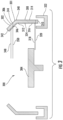
- Figure 3 depicts a cross-sectional view of a portion of a CMP tool component in the form of a splash cover 302 of a CMP tool 300. Only a polishing station 304 is illustrated in Figure 3 .
- the tool 300 is configured essentially the same as the tool 100 described in Figure 1 , except for one or more of the components of the tool 300 having a hydrophobic coating.
- the splash cover 302 circumscribes the polishing station 304.
- the splash cover 302 is used to block the polishing fluid from spinning off of the polishing station 304 and coating other areas of the CMP tool 300.
- the splash cover 302 includes a body 301 and a hydrophobic layer 324 disposed on the body 301.
- the body 301 has an upper side 306 and a lower side 308.
- the lower side 308 includes a lower edge 310, an upper edge 312, an outer surface 314, and an inner surface 316.
- the upper edge 312 is opposite the lower edge 310 and extends in an upward and inward direction towards the upper side 306.
- the outer surface 314 has an outer diameter 318.
- the inner surface 316 has an inner diameter 320.
- the inner diameter 320 is less than the outer diameter 318.
- the outer surface 314 and the inner surface 316 are concentric about a central axis.
- the upper side 306 includes a lower edge 340, an upper edge 342, an outer surface 344, and an inner surface 346.
- the upper edge 342 extends radially inward from the lower edge 340 of the upper side 306 in an upwards direction.
- the lower edge 340 of the upper side 306 is integral with the upper edge 312 of the lower side 308 to form a continuous splash cover 302.
- the outer surface 344 has an outer diameter 348.
- the outer diameter 348 of the upper side 306 is less than the outer diameter 318 of the lower side 308.
- the inner surface 346 has an inner diameter 350.
- the inner diameter 350 of the upper side 306 is less than both the inner diameter 320 of the lower side 308 and the outer diameter 348 of the upper side 306.
- Beneath the splash cover 302 may be a trough 322.
- the trough 322 collects the excess fluid or slurry that is directed downwards by the curvature of the splash cover 302.
- the fluid that contacts the splash cover 302 may contain material removed from the substrate, material from the polishing surface, abrasive particles or chemical reagents, such as sodium hydroxide, or deionized water.
- the hydrophobic layer 324 deposited on the body 301 of the splash cover 302 prevents erosion and sticking particles.
- the hydrophobic layer 324 may be placed on the inner surface 316 of the lower side 308 and the inner surface 346 of the upper side 306.
- the hydrophobic layer 324 extends the life of the splash cover 302 by delaying erosion. The presence of the hydrophobic layers 324 results in substantially less wetting of the carrier splash cover 302. Thus, rather than wetting the splash cover, the polishing fluid will easily roll off the surface the splash cover 302.
- erosion of the splash cover 302 will be substantially less, thus increasing the life of the splash cover 302. Additionally, if the polishing fluid is a slurry, the substantially less wetting results in less slurry particles adhering to the splash cover 302. Less slurry particles adhering to the splash cover 302 reduces the likelihood of the slurry particles dislodging the particles from the surface of the splash cover and falling onto the polishing stations.
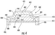
- FIG. 4 depicts a cross sectional view of one embodiment of a CMP tool component in the form of a carrier head assembly 400.
- the carrier head assembly 400 includes a carrier head 401, a retaining ring 426, a carrier cover 403, and a membrane 409.
- the carrier head 401 includes a body 411.
- the body 411 has an exposed upper surface 402, a bottom surface 404, an inner wall 406, and an outer wall 408.
- the upper surface 402 is substantially parallel to the bottom surface 404.
- the inner wall 406 further includes a first end 436, a second end 446, and an inner diameter 410.
- the outer wall 408 further includes a first end 438, a second end 448, and an outer diameter 412.
- the outer diameter 412 is larger than the inner diameter 410.
- a ledge 414 is formed in the carrier cover 403 by the inner diameter 410 and the outer diameter 412.
- the ledge 414 is substantially parallel to both the upper surface 402 and the bottom surface 404.
- the ledge 414 may be at a 90° angle with respect to the outer diameter 412.
- the membrane 409 is disposed beneath the bottom surface of the carrier head 401 and is circumscribed by the retaining ring 426.
- the membrane 409 provides a mounting surface for a substrate (not shown), when the carrier head 401 picks up a substrate to move the substrate among the stations (not shown).
- the carrier cover 403 includes a body 413 and a hydrophobic layer 425 disposed on the body 413.
- the body 413 is configured to fit over the carrier head such that the exposed upper surface 402, ledge 414, walls 406, 408, are covered.
- the carrier cover 403 is exposed to the polish fluid during polishing.
- the polishing fluid that is delivered to the polishing station may contact the carrier cover 403 and/or the carrier head 401.
- the polishing fluid may be a slurry that contains abrasive particles or chemical reagents, such as sodium hydroxide, or may be deionized water.
- the hydrophobic layer 425 extends the life of these components by delaying erosion. The presence of the hydrophobic layer 425 results in substantially less wetting of the carrier head 401 and carrier cover 403.
- the polishing fluid will easily roll off the surface the carrier head 401 and carrier cover 403. Therefore, erosion of the carrier head 401 and the carrier cover 403 will be substantially less, thus increasing the lives of the carrier head 401 and the carrier cover 403. Additionally, if the polishing fluid is a slurry, the substantially less wetting results in less slurry particles adhering to the carrier head 401 and the carrier cover 403. Less slurry particles adhering to the carrier head 401 and the carrier cover 403 reduces the likelihood of the slurry particles dislodging the particles from the surface of the component and falling onto the polishing stations.
- FIG. 5 shows a side view of a CMP tool component in the form of a polishing fluid delivery arm assembly 500.
- the polishing fluid delivery arm assembly 500 includes a fluid delivery arm 503, a base member 502, nozzles 504, and fluid delivery hoses (not shown).
- the fluid delivery arm 503 includes a body 501 and a hydrophobic layer 508 disposed on the body 501.
- the body 501 includes a top elongated surface 506, a first lateral side 510, a second lateral side 512 opposite the first lateral side 510, a bottom 514, a first end 580, and a second end 582.
- the first end 580 is coupled to the base member 502.
- the elongated surface 506 runs from the first end 580 to the second end 582.
- the second end 582 hangs out and over the polishing station (not shown).
- the nozzles 504 are located on the bottom 514 of the body 501.
- the nozzles 504 provide a polishing fluid to the surface of a substrate (not shown).
- Fluid delivery hoses bring the polishing fluid to the nozzles 504 for dispersion on to the polishing surface on which the substrate is polished.
- the entire body 501 may be covered with the hydrophobic layer 508.
- at least one of the first lateral side 510, the opposing second lateral side 512, top elongated surface 506, or the bottom 514 may be covered with the hydrophobic layer 508.
- Polishing fluid may contact the fluid delivery arm 503 when the nozzles 504 provide a polishing fluid to the polishing surface of the polishing station 111 when polishing a substrate.
- the presence of the hydrophobic layer 508 results in substantially less wetting of the fluid delivery arm 503.
- the polishing fluid will easily roll off the surface of the fluid delivery arm 503. Therefore, erosion of the fluid delivery arm 503 will be substantially less, thus increasing the life of the fluid delivery arm 503.
- the polishing fluid is a slurry
- the substantially less wetting results in less slurry particles adhering to the fluid delivery arm 503.
- Less slurry particles adhering to the fluid delivery arm 503 reduces the likelihood of the slurry particles dislodging the particles from the surface of the component and falling onto the polishing stations and scratching the substrate. Thus, there is a higher device quality and yield.
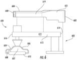
- Figure 6 depicts one embodiment of a portion of a polishing apparatus assembly 600 for polishing a substrate 610.
- the portion of a polishing apparatus assembly 600 includes a carriage 602, a plurality of arms 612, an arm cover 621, and a polishing head 606.
- Each arm 612 has a body 613.
- the body 613 includes a first end 614 and a second end 616.
- the first end 614 of the body 613 is coupled to the carriage 602.
- the second end 616 of the body 613 extends from the carriage 602, over a polishing station (not shown).
- the second end 616 of the body 613 is coupled to the polishing head 606.
- the polishing head 606 includes a body 607 and a hydrophobic layer 604 disposed on the body 607. A recess 608 is formed in the body 607. The polishing head 606 retains the substrate 610 in the recess 608 that faces the polishing station. The polishing head 606 may press the substrate 610 against a polishing material (not shown) during processing. The polishing head 606 may be stationary or rotate, isolate, move orbitally, linearly or a combination of motions while pressing the substrate 610 against the polishing material.
- the arm cover 621 may be placed over an arm 612 from the first end 614 to the second end 616.
- the arm cover 621 may further protect the arm 612 from fluid.
- the arm cover 621 includes a body 619 having a hydrophobic layer 604 disposed thereon.
- the body 619 has a first end 680 and a second end 682.
- the body 619 has a width slightly wider than the width of the arm 612 and a length slightly longer than the length of the arm 612, such that the arm cover 621 may be fitted over the arm 612.
- the presence of the hydrophobic layer 604 on the polishing head 606 and the arm cover 621 results in substantially less wetting of the arm cover 621 and the polishing head 606.
- the polishing fluid will easily roll off the polishing head 606 and the arm cover 621 of the polishing head 606 and the arm cover 621. Therefore, erosion of the polishing head 606 and the arm cover 621 will be substantially less, thus increasing the life of the polishing head 606 and the arm cover 621. Additionally, if the polishing fluid is a slurry, the substantially less wetting results in less slurry particles adhering to the polishing head 606 and the arm cover 621.
- the hydrophobic layer results in a higher device quality and yield.
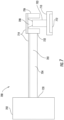
- FIG. 7 is a side view of a CMP tool component in the form of a pad conditioning arm assembly 700.
- the pad conditioning arm assembly 700 includes a body 701 having a base 702, a pad conditioning arm 704, and a conditioner head 706.
- the pad conditioning arm 704 has a first end 720, coupled with the base 702, and a second end 722, coupled to the conditioner head 706.
- the conditioner head 706 further includes a body 703.
- the body 703 has a hydrophobic layer 714 disposed thereon.
- the body 703 may be coupled to a rotable and vertically movable end effector 710 that holds a conditioning disk 712.
- the conditioning disk 712 has a bottom surface embedded with diamond abrasives, which can be rubbed against the surface of the polishing pad to retexture the pad.
- the conditioning disk 712 can be held in the end effector 710 by magnets (not shown), or mechanical fasteners (not shown).
- a gimbal mechanism (not shown) may be coupled between the end effector 710 and the conditioner head 706, the gimbal mechanism allowing the end effector 710 to tilt at an angle relative to the pad conditioning arm 704.
- Vertical motion of the end effector 710 and control of the pressure of the conditioning disk 712 can be provided by a vertical actuator (not shown) in the conditioner head 706, such as a pressurizable chamber 708 positioned to apply a downward pressure to the end effector 710.
- the components of the pad conditioning arm assembly 700 are susceptible to contact with the fluid or slurry used. Over time, continuous contact with the fluid or slurry may result in erosion of these components.
- the presence of the hydrophobic layer 714 results in substantially less wetting of the arms 704 and the pad conditioner head 706.
- the polishing fluid will easily roll off the surfaces of the polishing pad conditioning arm 704 and the conditioner head 706. Therefore, erosion of the polishing pad conditioning arm 704 and the conditioner head 706 will be substantially less, thus increasing the lives of the polishing pad conditioning arm 704 and the conditioner head 706.
- the polishing fluid is a slurry
- the substantially less wetting results in less slurry particles adhering to the polishing pad conditioning arm 704 and the conditioner head 706.
- Less slurry particles adhering to the polishing pad conditioning arm 704 and the conditioner head 706 reduces the likelihood of the slurry particles dislodging the particles from the surface of the component and falling onto the polishing stations and scratching the substrate. Thus, there is a higher device quality and yield.
Landscapes
- Engineering & Computer Science (AREA)
- Mechanical Engineering (AREA)
- Finish Polishing, Edge Sharpening, And Grinding By Specific Grinding Devices (AREA)
- Mechanical Treatment Of Semiconductor (AREA)
Abstract
Description
- Embodiments described herein generally relate to a component for use in a chemical mechanical polishing tool, wherein the component includes a hydrophobic layer disposed on a surface of the component.
- The present disclosure relates generally to chemical mechanical polishing of substrates, and more particularly to components of a chemical mechanical polishing apparatus.
- Integrated circuits are typically formed on substrates, such as silicon wafers, by sequential deposition of conductive, semiconductive, or insulative layers. After each layer is deposited, the layer is etched to create circuitry features. As a series of layers are sequentially deposited and etched, the outer or uppermost surface of the substrate, i.e., the exposed surface of the substrate, becomes increasingly non-planar. This non-planar outer surface presents a problem for the integrated circuit manufacturer. Therefore, there is a need to periodically planarize the substrate surface to provide a flat surface.
- Chemical mechanical polishing (CMP) is one accepted method of planarization. CMP typically includes the substrate mounted on a carrier or polishing head. The exposed surface of the substrate is then placed against a rotating polishing pad. The carrier head provides a controllable load, i.e., pressure, on the substrate to push the substrate against the polishing pad. In addition, the carrier head may rotate to provide additional motion between the substrate and polishing surface.
- A polishing slurry, including an abrasive and at least one chemically-reactive agent, may be supplied to the polishing pad to provide an abrasive chemical solution at the interface between the pad and the substrate.
- The polishing slurry may also contact and adhere to components of the CMP tool. Over time, the polishing slurry can rub over the surface of the components thereby dislodging component particles. Some of these particles may fall on to the polishing pad, which may result in scratching of the substrate. Scratches may result in substrate defects, which lead to performance degradation while polishing of the finished device. Additionally, the slurry particles may begin to erode the components of the CMP tool that are contacted by the slurry. Thus, the life spans of those parts are decreased, and the parts need to be replaced more readily.
- Therefore, there is a need for improved components for use in CMP tools.
- In one embodiment, a component for a CMP tool is disclosed herein. The component includes a body having a surface that will be exposed to a polishing fluid when the CMP tool is polishing a substrate and a hydrophobic layer disposed on the surface of the body. The hydrophobic layer having a fluid contact angle of at least 90°.
- In another embodiment, a component for a CMP tool is disclosed herein. The component includes a ring shaped body and a hydrophobic layer. The ring shaped body is defined by a lower side and an upper side. The lower side includes a lower edge, an upper edge, an outer surface having an outer diameter, an inner surface having an inner diameter, and a first hydrophobic layer. The upper edge extends towards the upper side. The inner diameter is less than the outer diameter. The outer surface and the inner surface are concentric about a central axis. The first hydrophobic layer is disposed on the inner surface of the lower side. The first hydrophobic layer has a contact angle of at least 90° when a fluid contacts a portion of the inner surface of the lower side. The upper side includes a lower edge, an upper edge, and outer surface having an outer diameter, an inner surface having an inner diameter, and a second hydrophobic layer. The lower edge is integral with the upper edge of the lower side. The upper edge of the upper side extends radially inward from the inner edge of the upper surface in an upwards direction. The outer diameter of the upper side is less than the outer diameter of the lower side. The inner diameter of the upper side is less than the inner diameter of the lower side. The second hydrophobic layer has a contact angle of at least 90° when a fluid contacts a portion of the inner surface of the upper side.
- In yet another embodiment, a component in a CMP tool is disclosed herein. The component includes a disk shaped body and a hydrophobic layer deposited on the disk shaped body. The disk shaped body has a top surface, a bottom surface, an outer wall, an inner wall, and a ledge. The bottom surface is substantially parallel to the top surface. The outer wall is perpendicular to the bottom surface. The outer wall includes an outer diameter, a first end, and a second end. The first end of the outer wall is integral with the bottom surface. The second end is opposite the first end. The inner wall is perpendicular to the top surface. The inner wall includes an inner diameter, a first end, and a second end. The inner diameter is less than the outer diameter. The second end of the inner wall is integral with the top surface. The ledge is defined by the outer wall and the inner wall. The ledge is perpendicular to the outer wall and the inner wall. The ledge has a first end and a second end. The first end of the ledge is integral to the second end of the outer wall. The second end of the ledge is radially inward from the first end of the ledge. The second end of the ledge is integrally connected with the first end of the other wall. The second end of the outer wall is radially inward from the first end of the outer wall, towards the top surface. The hydrophobic layer has a contact angle of at least 90° when a fluid contacts a portion of disk shaped body.
- So that the manner in which the above recited features of the present disclosure can be understood in detail, a more particular description of the disclosure, briefly summarized above, may be had by reference to embodiments, some of which are illustrated in the appended drawings. It is to be noted, however, that the appended drawings illustrate only typical embodiments of the disclosure and are therefore not to be considered limiting of its scope, for the disclosure may admit to other equality effective.
-
Figure 1 illustrates a top view of a chemical mechanical polishing (CMP) tool for polishing a substrate, according to one embodiment. -
Figure 2A illustrates a side view of a portion of a CMP tool component without a hydrophobic layer deposited thereon, according to one embodiment. -
Figure 2B illustrates a side view of a portion of a CMP tool component with a hydrophobic layer deposited thereon, according to one embodiment. -
Figure 2C illustrates a side view of a portion of a CMP tool component having a thicker hydrophobic layer than that deposited on the CMP tool component illustrated inFigure 2B , according to one embodiment. -
Figure 3 illustrates a side view of a splash cover having a hydrophobic layer deposited thereon, according to one embodiment. -
Figure 4 illustrates a side view of a carrier cover having a hydrophobic layer deposited thereon, according to one embodiment. -
Figure 5 illustrates a side view of a polishing fluid delivery arm having a hydrophobic layer deposited thereon, according to one embodiment. -
Figure 6 illustrates a side view of one embodiment of a portion of a polishing apparatus having a hydrophobic layer deposited thereon, according to one embodiment. -
Figure 7 illustrates a side view of a pad conditioning arm of a CMP tool having a hydrophobic layer deposited thereon, according to one embodiment. - To facilitate understanding, identical reference numerals have been used, where possible, to designate identical elements that are common to the figures. It is contemplated that elements disclosed in one embodiment may be beneficially utilized on other embodiments without specific recitation.
- Embodiments of the present disclosure are described herein in accordance with components of a CMP tool.
-
Figure 1 depicts a conventional chemical mechanical polishing (CMP)tool 100 for polishing a substrate (not shown). TheCMP tool 100 may include abase 101. Thebase 101 includes acarriage 102 and a plurality ofstations 108. Thecarriage 102 is centrally disposed on thebase 101. Thecarriage 102 may include a plurality ofarms 110, each supporting a polishinghead 112. Thearms 110 extend from thecarriage 102 out over eachstation 108. The polishing heads 112 are generally supported above thestations 108. The polishing heads 112 include a recess (not shown) configured to retain a substrate during polishing. Thestations 108 may be, for example, atransfer station 113 or a polishing station 111. Twoarms 110 depicted inFigure 1 are shown in phantom such that thetransfer station 113 and polishing station 111 of thefirst station 108 may be shown. Thecarriage 102 is indexable such that the polishinghead 112 may be moved between the polishing station 111 and thetransfer station 113. -
Conditioning devices 134 may be disposed on the base 101 adjacent to each of the polishing stations 111. Theconditioning devices 134 may be used to periodically condition the polishing surface of the polishing stations 111 to maintain uniform polishing results. - Each polishing station 111 has a
fluid delivery arm 109. Thefluid delivery arm 109 delivers a polishing fluid to the polishing surface of the polishing station 111 so that a substrate may be polished. When the fluid is delivered to the polishing station 111, the polishing fluid may come into contact with components of the CMP tool. If a slurry is used as the polishing fluid, the slurry particles adhere to the different components of the CMP tool. Over time, the polishing slurry can rub over the surface of a component thereby dislodging component particles. Some of these particles may fall onto the polishing surface, and potentially become a source of scratches on the substrate being polished. These scratches may result in poor device performance and high defects. Additionally, the slurry particles may begin to erode those components of the CMP tool. Thus, there is a need to limit the contact between the fluid and the components of the CMP tool such that erosion of the components is delayed and the life span is extended. -
Figures 2A-2C compare CMP tool components with and without a hydrophobic layer applied to an exterior of the CMP tool component. -
Figure 2A illustrates a portion of a CMP tool component that does not have a hydrophobic layer on an exterior surface. The angle at which a fluid contacts the surface of the CMP tool component is referred to as the contact angle. The contact angle is determined by the resultant between adhesive and cohesive surfaces. When a fluid contacts the surface of the portion of the CMP tool component without a hydrophobic layer as illustrated inFigure 2A , thecontact angle 206 between the fluid and the CMP tool component is about 60°. A surface which has a high degree of wetting and a contact angle less than 90° is referred to as a hydrophilic surface. The measure of wetting of a surface is inversely related to the contact angle. The low contact angle between the fluid and the CMP tool components illustrates that the CMP tool has a high degree of wetting. A high degree of wetting results in more slurry particles adhering to an exterior surface of the CMP tool component. More slurry contact with CMP tool component increases the likelihood of dislodging some surface particles from the CMP tool component. Such dislodged component particles will fall onto the polishing surface of the polishing station and scratch the substrate. - The CMP tool components illustrated in
Figures 2B-2C have a hydrophobic layer disposed an exterior surface of the component. The hydrophobic layer may be in the form of monomolecular layers (adsorbed orientated layers about one molecule thick) or lacquer films by treating a material with solutions, emulsions, or less frequently, vapors of hydrophobic agents, which are substances that interact weakly with water but attach themselves to a surface. The hydrophobic layer may be deposited on a CMP tool component using a plasma treatment performed in a plasma chamber. The plasma treatment utilizes a low-pressure plasma system, which is inexpensive and consumes minimal gas. In hydrophobic deposition process, monomers are introduced into the chamber and react chemically among each other to form polymers. These polymers then deposit as a hydrophobic layer onto the treated component. The monomers that are introduced into the chamber may be, for example, hexamethyldisiloxane, heptadecafluorodecyltrimethoxysilane, poly(tetrafluoroethylene), poly(propylene), octadecyldimethylchlorosilane, octadecyltrichlorosilane, tris(trimethylsiloxy)silylethyl-dimethylchlorosilane, octyldimethylchlorosilane, or dimethyldichlorosilane. - The contact angle between the fluid and the surface may be measured using different techniques. For example, one technique includes placing a sample, in this case a component of a CMP tool, on a flat surface. A constant volume of water or slurry solution is then dispersed onto the component with a pipette. While the droplets are on the hydrophobic layer disposed on the exterior of the component, a picture is taken of the droplet disposed on the layer. The angle between the droplet and the surface may be measured to determine the contact angle.
- The contact angle of the hydrophobic layer may also be determined using a VCMA Optima analyser. The VCMA Optima analyser utilizes a precision camera and advanced PC technology to capture static or dynamic images of the droplet and determine tangent lines for the basis of contact angle measurement. A manual or automatic syringe may dispense the test liquid. Computerized measurement eliminates the human error element in measuring the contact angle. Dynamic images are able to be captured for time sensitive analysis.
- Referring back to
Figure 2A, Figure 2A depicts adroplet 202 of fluid on a conventionalCMP tool component 200, which does not have a hydrophobic layer. Thecontact angle 206 of the droplet is about 60°. The low contact angle indicates a high degree of wetting of the surface of thecomponent 200, which may contribute to erosion of thecomponent 200 over time. Thus, the life span of theCMP tool component 200 is undesirably short. -
Figure 2B depicts aCMP tool component 200 having ahydrophobic layer 204 disposed on the top surface of thecomponent 200. Thehydrophobic layer 204 may be applied to thecomponent 200 by plasma treatment or other suitable methods. Adroplet 202 of fluid disposed on thehydrophobic layer 204 of theCMP tool component 200 has acontact angle 212. Thehydrophobic layer 204 has ahigher contact angle 212 than that of the surface of theconventional CMP tool 100 that does not have the hydrophobic layer. Thecontact angle 212 formed between thedroplet 202 and thehydrophobic layer 204 on thecomponent 200 is at least 90°. Thehigher contact angle 212, shown inFigure 2B , indicates substantially less wetting for the surface. Thus, rather than wetting theCMP tool component 200, thedroplet 202 easily rolls off the surface of thecomponent 200. Therefore, erosion of thecomponent 200 will be substantially less, thus increasing the life of thecomponent 200. Additionally, if the polishing fluid is a slurry, the substantially less wetting results in less slurry particles adhering to thecomponent 200. Less slurry particles adhering to thecomponent 200 reduces the likelihood of the slurry particles dislodging surface particles of CMP tool components and eventually falling onto the polishing stations. -
Figure 2C depicts aCMP tool component 200 having a thickerhydrophobic layer 208 compared to thehydrophobic layer 204 illustrated inFigure 2B . The thickness of thehydrophobic layer 208 may be controlled by the time thecomponent 200 is exposed to the hydrophobic layer deposition process. The longer theCMP tool component 200 is exposed to the hydrophobic layer deposition process process, the thicker thehydrophobic layer 208. The thickness of the hydrophobic layer may range from 400 nm to 1600 nm. As the thickness of thehydrophobic layer 208 increases, the contact angle formed between the hydrophobic layer and the fluid increases. As the contact angle increases, the degree of wetting decreases. Thus, the thicker the hydrophobic layer, the lower the degree of wetting for the surface on which the hydrophobic layer is formed. The thickerhydrophobic layer 208 has thecontact angle 214 between thedroplet 202 and thecomponent 200 of about 140°. This results in a low degree of wetting. Thus rather than wetting theCMP tool component 200, thedroplet 202 easily rolls off the surface of thecomponent 200. Therefore, erosion of thecomponent 200 will be substantially less, thus increasing the life of thecomponent 200. Additionally, if the polishing fluid is a slurry, the substantially less wetting results in less slurry particles adhering to thecomponent 200. Less slurry particles adhering to thecomponents 200 reduces the likelihood of the slurry particles falling onto the polishing stations. -
Figure 3 depicts a cross-sectional view of a portion of a CMP tool component in the form of asplash cover 302 of aCMP tool 300. Only a polishingstation 304 is illustrated inFigure 3 . Thetool 300 is configured essentially the same as thetool 100 described inFigure 1 , except for one or more of the components of thetool 300 having a hydrophobic coating. Thesplash cover 302 circumscribes the polishingstation 304. Thesplash cover 302 is used to block the polishing fluid from spinning off of the polishingstation 304 and coating other areas of theCMP tool 300. Thesplash cover 302 includes abody 301 and ahydrophobic layer 324 disposed on thebody 301. Thebody 301 has anupper side 306 and alower side 308. Thelower side 308 includes a lower edge 310, anupper edge 312, anouter surface 314, and aninner surface 316. Theupper edge 312 is opposite the lower edge 310 and extends in an upward and inward direction towards theupper side 306. Theouter surface 314 has anouter diameter 318. Theinner surface 316 has aninner diameter 320. Theinner diameter 320 is less than theouter diameter 318. Theouter surface 314 and theinner surface 316 are concentric about a central axis. - The
upper side 306 includes alower edge 340, anupper edge 342, anouter surface 344, and aninner surface 346. Theupper edge 342 extends radially inward from thelower edge 340 of theupper side 306 in an upwards direction. Thelower edge 340 of theupper side 306 is integral with theupper edge 312 of thelower side 308 to form acontinuous splash cover 302. Theouter surface 344 has anouter diameter 348. Theouter diameter 348 of theupper side 306 is less than theouter diameter 318 of thelower side 308. Theinner surface 346 has aninner diameter 350. Theinner diameter 350 of theupper side 306 is less than both theinner diameter 320 of thelower side 308 and theouter diameter 348 of theupper side 306. - Beneath the
splash cover 302 may be atrough 322. Thetrough 322 collects the excess fluid or slurry that is directed downwards by the curvature of thesplash cover 302. - The fluid that contacts the
splash cover 302 may contain material removed from the substrate, material from the polishing surface, abrasive particles or chemical reagents, such as sodium hydroxide, or deionized water. Thehydrophobic layer 324 deposited on thebody 301 of thesplash cover 302 prevents erosion and sticking particles. In one embodiment, thehydrophobic layer 324 may be placed on theinner surface 316 of thelower side 308 and theinner surface 346 of theupper side 306. Thehydrophobic layer 324 extends the life of thesplash cover 302 by delaying erosion. The presence of thehydrophobic layers 324 results in substantially less wetting of thecarrier splash cover 302. Thus, rather than wetting the splash cover, the polishing fluid will easily roll off the surface thesplash cover 302. Therefore, erosion of thesplash cover 302 will be substantially less, thus increasing the life of thesplash cover 302. Additionally, if the polishing fluid is a slurry, the substantially less wetting results in less slurry particles adhering to thesplash cover 302. Less slurry particles adhering to thesplash cover 302 reduces the likelihood of the slurry particles dislodging the particles from the surface of the splash cover and falling onto the polishing stations. -
Figure 4 depicts a cross sectional view of one embodiment of a CMP tool component in the form of acarrier head assembly 400. Thecarrier head assembly 400 includes acarrier head 401, a retainingring 426, acarrier cover 403, and amembrane 409. Thecarrier head 401 includes abody 411. Thebody 411 has an exposedupper surface 402, abottom surface 404, aninner wall 406, and anouter wall 408. Theupper surface 402 is substantially parallel to thebottom surface 404. Theinner wall 406 further includes afirst end 436, asecond end 446, and aninner diameter 410. Theouter wall 408 further includes afirst end 438, asecond end 448, and anouter diameter 412. Theouter diameter 412 is larger than theinner diameter 410. Aledge 414 is formed in thecarrier cover 403 by theinner diameter 410 and theouter diameter 412. Theledge 414 is substantially parallel to both theupper surface 402 and thebottom surface 404. Theledge 414 may be at a 90° angle with respect to theouter diameter 412. Themembrane 409 is disposed beneath the bottom surface of thecarrier head 401 and is circumscribed by the retainingring 426. Themembrane 409 provides a mounting surface for a substrate (not shown), when thecarrier head 401 picks up a substrate to move the substrate among the stations (not shown). - The
carrier cover 403 includes abody 413 and ahydrophobic layer 425 disposed on thebody 413. Thebody 413 is configured to fit over the carrier head such that the exposedupper surface 402,ledge 414,walls carrier cover 403 is exposed to the polish fluid during polishing. The polishing fluid that is delivered to the polishing station may contact thecarrier cover 403 and/or thecarrier head 401. The polishing fluid may be a slurry that contains abrasive particles or chemical reagents, such as sodium hydroxide, or may be deionized water. Thehydrophobic layer 425 extends the life of these components by delaying erosion. The presence of thehydrophobic layer 425 results in substantially less wetting of thecarrier head 401 andcarrier cover 403. Thus, rather than wetting thecarrier head 401 andcarrier cover 403, the polishing fluid will easily roll off the surface thecarrier head 401 andcarrier cover 403. Therefore, erosion of thecarrier head 401 and thecarrier cover 403 will be substantially less, thus increasing the lives of thecarrier head 401 and thecarrier cover 403. Additionally, if the polishing fluid is a slurry, the substantially less wetting results in less slurry particles adhering to thecarrier head 401 and thecarrier cover 403. Less slurry particles adhering to thecarrier head 401 and thecarrier cover 403 reduces the likelihood of the slurry particles dislodging the particles from the surface of the component and falling onto the polishing stations. -
Figure 5 shows a side view of a CMP tool component in the form of a polishing fluiddelivery arm assembly 500. The polishing fluiddelivery arm assembly 500 includes afluid delivery arm 503, abase member 502,nozzles 504, and fluid delivery hoses (not shown). Thefluid delivery arm 503 includes abody 501 and ahydrophobic layer 508 disposed on thebody 501. Thebody 501 includes a topelongated surface 506, a firstlateral side 510, a secondlateral side 512 opposite the firstlateral side 510, a bottom 514, afirst end 580, and asecond end 582. Thefirst end 580 is coupled to thebase member 502. Theelongated surface 506 runs from thefirst end 580 to thesecond end 582. Thesecond end 582 hangs out and over the polishing station (not shown). Thenozzles 504 are located on thebottom 514 of thebody 501. Thenozzles 504 provide a polishing fluid to the surface of a substrate (not shown). Fluid delivery hoses bring the polishing fluid to thenozzles 504 for dispersion on to the polishing surface on which the substrate is polished. - The
entire body 501 may be covered with thehydrophobic layer 508. Alternatively, at least one of the firstlateral side 510, the opposing secondlateral side 512, topelongated surface 506, or the bottom 514 may be covered with thehydrophobic layer 508. Polishing fluid may contact thefluid delivery arm 503 when thenozzles 504 provide a polishing fluid to the polishing surface of the polishing station 111 when polishing a substrate. The presence of thehydrophobic layer 508 results in substantially less wetting of thefluid delivery arm 503. Thus, rather than wetting the CMP toolfluid delivery arm 503 the polishing fluid will easily roll off the surface of thefluid delivery arm 503. Therefore, erosion of thefluid delivery arm 503 will be substantially less, thus increasing the life of thefluid delivery arm 503. Additionally, if the polishing fluid is a slurry, the substantially less wetting results in less slurry particles adhering to thefluid delivery arm 503. Less slurry particles adhering to thefluid delivery arm 503 reduces the likelihood of the slurry particles dislodging the particles from the surface of the component and falling onto the polishing stations and scratching the substrate. Thus, there is a higher device quality and yield. -
Figure 6 depicts one embodiment of a portion of a polishingapparatus assembly 600 for polishing asubstrate 610. The portion of a polishingapparatus assembly 600 includes acarriage 602, a plurality ofarms 612, anarm cover 621, and a polishinghead 606. Eacharm 612 has abody 613. Thebody 613 includes afirst end 614 and asecond end 616. Thefirst end 614 of thebody 613 is coupled to thecarriage 602. Thesecond end 616 of thebody 613 extends from thecarriage 602, over a polishing station (not shown). Thesecond end 616 of thebody 613 is coupled to the polishinghead 606. - The polishing
head 606 includes abody 607 and ahydrophobic layer 604 disposed on thebody 607. Arecess 608 is formed in thebody 607. The polishinghead 606 retains thesubstrate 610 in therecess 608 that faces the polishing station. The polishinghead 606 may press thesubstrate 610 against a polishing material (not shown) during processing. The polishinghead 606 may be stationary or rotate, isolate, move orbitally, linearly or a combination of motions while pressing thesubstrate 610 against the polishing material. - The
arm cover 621 may be placed over anarm 612 from thefirst end 614 to thesecond end 616. Thearm cover 621 may further protect thearm 612 from fluid. Thearm cover 621 includes abody 619 having ahydrophobic layer 604 disposed thereon. Thebody 619 has a first end 680 and asecond end 682. Thebody 619 has a width slightly wider than the width of thearm 612 and a length slightly longer than the length of thearm 612, such that thearm cover 621 may be fitted over thearm 612. The presence of thehydrophobic layer 604 on the polishinghead 606 and thearm cover 621 results in substantially less wetting of thearm cover 621 and the polishinghead 606. Thus, rather than wetting the CMPtool polishing head 606 and thearm cover 621, the polishing fluid will easily roll off the polishinghead 606 and thearm cover 621 of the polishinghead 606 and thearm cover 621. Therefore, erosion of the polishinghead 606 and thearm cover 621 will be substantially less, thus increasing the life of the polishinghead 606 and thearm cover 621. Additionally, if the polishing fluid is a slurry, the substantially less wetting results in less slurry particles adhering to the polishinghead 606 and thearm cover 621. Less slurry particles adhering to the polishinghead 606 and thearm cover 621 reduces the likelihood of the slurry particles dislodging the particles from the surface of the component and falling onto the polishing stations and scratching the substrate. Thus, the hydrophobic layer results in a higher device quality and yield. -
Figure 7 is a side view of a CMP tool component in the form of a padconditioning arm assembly 700. The padconditioning arm assembly 700 includes abody 701 having a base 702, apad conditioning arm 704, and aconditioner head 706. Thepad conditioning arm 704 has afirst end 720, coupled with thebase 702, and asecond end 722, coupled to theconditioner head 706. Theconditioner head 706 further includes abody 703. Thebody 703 has ahydrophobic layer 714 disposed thereon. Thebody 703 may be coupled to a rotable and verticallymovable end effector 710 that holds aconditioning disk 712. Theconditioning disk 712 has a bottom surface embedded with diamond abrasives, which can be rubbed against the surface of the polishing pad to retexture the pad. Theconditioning disk 712 can be held in theend effector 710 by magnets (not shown), or mechanical fasteners (not shown). A gimbal mechanism (not shown) may be coupled between theend effector 710 and theconditioner head 706, the gimbal mechanism allowing theend effector 710 to tilt at an angle relative to thepad conditioning arm 704. - Vertical motion of the
end effector 710 and control of the pressure of theconditioning disk 712 can be provided by a vertical actuator (not shown) in theconditioner head 706, such as apressurizable chamber 708 positioned to apply a downward pressure to theend effector 710. - During the polishing process, the components of the pad
conditioning arm assembly 700 are susceptible to contact with the fluid or slurry used. Over time, continuous contact with the fluid or slurry may result in erosion of these components. The presence of thehydrophobic layer 714 results in substantially less wetting of thearms 704 and thepad conditioner head 706. Thus, rather than wetting the polishingpad conditioning arm 704 and theconditioner head 706, the polishing fluid will easily roll off the surfaces of the polishingpad conditioning arm 704 and theconditioner head 706. Therefore, erosion of the polishingpad conditioning arm 704 and theconditioner head 706 will be substantially less, thus increasing the lives of the polishingpad conditioning arm 704 and theconditioner head 706. Additionally, if the polishing fluid is a slurry, the substantially less wetting results in less slurry particles adhering to the polishingpad conditioning arm 704 and theconditioner head 706. Less slurry particles adhering to the polishingpad conditioning arm 704 and theconditioner head 706 reduces the likelihood of the slurry particles dislodging the particles from the surface of the component and falling onto the polishing stations and scratching the substrate. Thus, there is a higher device quality and yield. - By depositing a hydrophobic layer on components of a CMP tool, erosion of the components is delayed and the life spans of these components are increased.
- The following aspects are disclosed:
- Item 1. A component for a CMP tool, the component comprising:
- a body having a surface that will be exposed to a polishing fluid when the CMP tool is polishing a substrate; and
- a hydrophobic layer disposed on the surface of the body, the hydrophobic layer having a fluid contact angle of at least 90°.
- Item 2. The component of item 1, wherein the hydrophobic layer has a thickness of at least 400 nm.
- Item 3. The component of item 1, wherein the component is a component for delivering a fluid in a CMP tool, the component for delivering a fluid in a CMP tool comprising:
an elongated member, wherein the elongated member further comprises:- a first end;
- a second end;
- an elongated upper surface extending between the first end and the second end; and
- a hydrophobic layer disposed on the elongated upper surface of the elongated member, the hydrophobic layer having a contact angle of at least 90° when a fluid contacts a portion of the elongated member.
- Item 4. The component of the item 3, wherein the contact angle is 140°.
- Item 5. A component for a CMP tool, the component comprising:
- a ring shaped body, wherein the ring shaped body is defined by a lower side and an upper side, the lower side further comprising:
- a lower edge;
- an upper edge, wherein the upper edge extends towards the upper side;
- an outer surface having an outer diameter;
- an inner surface having an inner diameter, wherein the inner diameter is less than the outer diameter, the outer surface and the inner surface concentric about a central axis; and
- a first hydrophobic layer disposed on the inner surface of the lower side, the first hydrophobic layer having a contact angle of at least 90° when a fluid contacts a portion of the inner surface of the lower side;
- the upper side further comprising:
- a lower edge, wherein the lower edge is integral with the upper edge of the lower side;
- an upper edge, wherein the upper edge extends radially inward from the inner edge of the upper surface in an upwards direction;
- an outer surface having an outer diameter, wherein the outer diameter of the upper side is less than the outer diameter of the lower side;
- an inner surface having an inner diameter, wherein the inner diameter of the upper side is less than the inner diameter of the lower side; and
- a second hydrophobic layer disposed on the inner surface of the upper side, the second hydrophobic layer having a contact angle of at least 90° when a fluid contacts a portion of the inner surface of the upper side.
- a ring shaped body, wherein the ring shaped body is defined by a lower side and an upper side, the lower side further comprising:
- Item 6. The component of item 5, wherein the second hydrophobic layer has a contact angle of 140°.
- Item 7. The component of item 5, wherein the second hydrophobic layer has a thickness of at least 400 nm.
- Item 8. The component of item 7, wherein the thickness of the second hydrophobic layer is 1600 nm.
- Item 9. The component of item 5, wherein the first hydrophobic layer has a contact angle of 140°.
- Item 10. The component of item 5, wherein the first hydrophobic layer has a thickness of at least 400 nm.
- Item 11. A component in a CMP tool, the component comprising:
a disk shaped body, the disk shaped body further comprising:- a top surface;
- a bottom surface, wherein the bottom surface is substantially parallel to the top surface;
- an outer wall, the outer wall perpendicular to the bottom surface, wherein the outer wall further comprises:
- an outer diameter;
- a first end, the first end of the outer wall integral with the bottom surface; and
- a second end opposite the first end;
- an inner wall, the inner wall perpendicular to the top surface, wherein the inner wall further comprises:
- an inner diameter, wherein the inner diameter is less than the outer diameter;
- a first end; and
- a second end, the second end of the inner wall integral with the top surface;
- a ledge defined by the outer wall and the inner wall, the ledge perpendicular to the outer wall and the inner wall, wherein the ledge has a first end and a second end, the first end of the ledge integral to the second end of the outer wall, the second end of the ledge radially inward from the first end of the ledge, the second end of the ledge integrally connected with the first end of the outer wall, the second end of the outer wall radially inward from the first end of the outer wall, towards the top surface; and
- a hydrophobic layer deposited on the disk shaped body, the hydrophobic layer having a contact angle of at least 90° when a fluid contacts a portion of disk shaped body.
- Item 12. The component of item 11, wherein the hydrophobic layer has a contact angle of 140°.
- Item 13. The component of item 11 wherein the hydrophobic layer has a thickness of at least 400 nm.
- Item 14. The component of item 13 wherein the thickness of the hydrophobic layer is 1600 nm.
- Item 15. The component of item 11, wherein the hydrophobic layer has a contact angle between 90° and 140°.
- While the foregoing is directed to embodiments of the present disclosure, other and further embodiments of the disclosure may be devised without departing from the basic scope thereof, and the scope thereof is determined by the claims that follow.
Claims (14)
- A component for a chemical mechanical polishing (CMP) tool, the component comprising:a body having a surface that will be exposed to a polishing fluid when the CMP tool is polishing a substrate; anda hydrophobic layer disposed on the surface of the body, the hydrophobic layer is formed from a monomer, wherein the monomer is selected from the group consisting of octadecyldimethylchlorosilane and octyldimethylchlorosilane.
- The component of claim 1, wherein the hydrophobic layer has a thickness from 400 nm to 1600 nm.
- The component of claim 1, wherein the component is a component for delivering a fluid in a CMP tool, the component for delivering a fluid in a CMP tool comprising:
an elongated member, wherein the elongated member further comprises:a first end;a second end; andan elongated upper surface extending between the first end and the second end, wherein the hydrophobic layer is disposed on the elongated upper surface of the elongated member. - The component of claim 3, wherein the component is a polishing fluid delivery arm assembly.
- The component of claim 3, wherein the component is a pad conditioning arm assembly.
- The component of claim 3, wherein the elongated member is an arm cover.
- The component of claim 1, wherein the component comprises a ring shaped body, the ring shaped body having the hydrophobic layer on an inner surface of the ring shaped body.
- The component of claim 7, wherein the hydrophobic layer has a contact angle of 140°.
- The component of claim 7, wherein the hydrophobic layer has a thickness of at least 400 nm, particularly wherein the hydrophobic layer has a thickness from 400 nm to 1600 nm, more particularly wherein the thickness of the hydrophobic layer is 1600 nm.
- The component of claim 9, wherein the hydrophobic layer has a contact angle of at least 90° when the fluid contacts a portion of the inner surface.
- The component of claim 1, wherein the component comprises a disk shaped body, the hydrophobic layer deposited on the disk shaped body.
- The component of claim 11, wherein the hydrophobic layer has a contact angle of 140°.
- The component of claim 11, wherein the hydrophobic layer has a thickness of at least 400 nm, particularly wherein the hydrophobic layer has a thickness from 400 nm to 1600 nm, more particularly wherein the thickness of the hydrophobic layer is 1600 nm.
- The component of claim 13, wherein the hydrophobic layer has a contact angle between 90° and about 140°.
Applications Claiming Priority (3)
| Application Number | Priority Date | Filing Date | Title |
|---|---|---|---|
| US201462094484P | 2014-12-19 | 2014-12-19 | |
| EP15870598.8A EP3234986B1 (en) | 2014-12-19 | 2015-11-19 | Components for a chemical mechanical polishing tool |
| PCT/US2015/061643 WO2016099790A1 (en) | 2014-12-19 | 2015-11-19 | Components for a chemical mechanical polishing tool |
Related Parent Applications (2)
| Application Number | Title | Priority Date | Filing Date |
|---|---|---|---|
| EP15870598.8A Division-Into EP3234986B1 (en) | 2014-12-19 | 2015-11-19 | Components for a chemical mechanical polishing tool |
| EP15870598.8A Division EP3234986B1 (en) | 2014-12-19 | 2015-11-19 | Components for a chemical mechanical polishing tool |
Publications (1)
| Publication Number | Publication Date |
|---|---|
| EP4216258A1 true EP4216258A1 (en) | 2023-07-26 |
Family
ID=56127288
Family Applications (2)
| Application Number | Title | Priority Date | Filing Date |
|---|---|---|---|
| EP23154241.6A Withdrawn EP4216258A1 (en) | 2014-12-19 | 2015-11-19 | Components for a chemical mechanical polishing tool |
| EP15870598.8A Active EP3234986B1 (en) | 2014-12-19 | 2015-11-19 | Components for a chemical mechanical polishing tool |
Family Applications After (1)
| Application Number | Title | Priority Date | Filing Date |
|---|---|---|---|
| EP15870598.8A Active EP3234986B1 (en) | 2014-12-19 | 2015-11-19 | Components for a chemical mechanical polishing tool |
Country Status (8)
| Country | Link |
|---|---|
| US (3) | US10434627B2 (en) |
| EP (2) | EP4216258A1 (en) |
| JP (1) | JP6661640B2 (en) |
| KR (2) | KR102487939B1 (en) |
| CN (1) | CN107000158B (en) |
| SG (1) | SG11201704364WA (en) |
| TW (1) | TWI679692B (en) |
| WO (1) | WO2016099790A1 (en) |
Families Citing this family (8)
| Publication number | Priority date | Publication date | Assignee | Title |
|---|---|---|---|---|
| CN112020570B (en) * | 2018-04-20 | 2023-11-28 | 柯尼卡美能达株式会社 | Transparent components and methods of manufacturing transparent components |
| KR102561647B1 (en) * | 2018-05-28 | 2023-07-31 | 삼성전자주식회사 | Conditioner and chemical mechanical polishing apparatus including the same |
| JP7186671B2 (en) * | 2019-06-24 | 2022-12-09 | 株式会社荏原製作所 | Cover for rocking part of substrate processing apparatus, rocking part of substrate processing apparatus, and substrate processing apparatus |
| US11890718B2 (en) * | 2020-01-17 | 2024-02-06 | Taiwan Semiconductor Manufacturing Co., Ltd. | Removable tray assembly for CMP systems |
| US11484987B2 (en) | 2020-03-09 | 2022-11-01 | Applied Materials, Inc. | Maintenance methods for polishing systems and articles related thereto |
| TWI772171B (en) * | 2021-09-08 | 2022-07-21 | 明志科技大學 | Protective film and protective film stack for chemical mechanical polishing pad dressers |
| WO2026019857A1 (en) * | 2024-07-19 | 2026-01-22 | Applied Materials, Inc. | Chemical mechanical polishing shielding |
| WO2026036246A1 (en) * | 2024-08-12 | 2026-02-19 | Applied Materials, Inc. | Platen droplet contamination reduction apparatus |
Citations (8)
| Publication number | Priority date | Publication date | Assignee | Title |
|---|---|---|---|---|
| JP2003179021A (en) * | 2001-12-11 | 2003-06-27 | Sony Corp | Chemical mechanical polishing equipment |
| US20050064709A1 (en) * | 2001-11-13 | 2005-03-24 | Tetsuo Shimomura | Grinding pad and method of producing the same |
| JP2006185901A (en) * | 2004-12-02 | 2006-07-13 | Dainippon Printing Co Ltd | Water-repellent separator for polymer electrolyte fuel cells |
| KR20070026020A (en) * | 2005-08-30 | 2007-03-08 | 강준모 | Retaining ring for chemical mechanical polishing |
| US20110159299A1 (en) * | 2006-10-03 | 2011-06-30 | Linforf Mattew R | Hydrophobic coating and method |
| WO2014097309A1 (en) * | 2012-12-17 | 2014-06-26 | Asian Paints Ltd. | Stimuli responsive self cleaning coating |
| US20140213158A1 (en) * | 2013-01-31 | 2014-07-31 | Ebara Corporation | Polishing apparatus |
| WO2014123376A1 (en) * | 2013-02-08 | 2014-08-14 | 국민대학교산학협력단 | Water and oil ultra-repellent structure and manufacturing method therefor |
Family Cites Families (31)
| Publication number | Priority date | Publication date | Assignee | Title |
|---|---|---|---|---|
| US7097544B1 (en) * | 1995-10-27 | 2006-08-29 | Applied Materials Inc. | Chemical mechanical polishing system having multiple polishing stations and providing relative linear polishing motion |
| US5990012A (en) * | 1998-01-27 | 1999-11-23 | Micron Technology, Inc. | Chemical-mechanical polishing of hydrophobic materials by use of incorporated-particle polishing pads |
| JP2000349054A (en) * | 1999-06-07 | 2000-12-15 | Asahi Chem Ind Co Ltd | Polishing pad for metal film |
| US6540595B1 (en) * | 2000-08-29 | 2003-04-01 | Applied Materials, Inc. | Chemical-Mechanical polishing apparatus and method utilizing an advanceable polishing sheet |
| JP2003133270A (en) * | 2001-10-26 | 2003-05-09 | Jsr Corp | Window material and polishing pad for chemical mechanical polishing |
| US20030211743A1 (en) * | 2002-05-07 | 2003-11-13 | Taiwan Semiconductor Manufacturing Co., Ltd. | Method for avoiding slurry sedimentation in CMP slurry delivery systems |
| KR100495659B1 (en) | 2002-06-21 | 2005-06-16 | 삼성전자주식회사 | Polishing station of a chemical mechanical polishing machine |
| JP4177214B2 (en) * | 2003-09-09 | 2008-11-05 | 関東電化工業株式会社 | Fluorine-containing copolymer, composition thereof, and coating thereof |
| US7335239B2 (en) * | 2003-11-17 | 2008-02-26 | Advanced Technology Materials, Inc. | Chemical mechanical planarization pad |
| JP4769790B2 (en) | 2005-02-07 | 2011-09-07 | 株式会社荏原製作所 | Substrate processing method, substrate processing apparatus, and control program |
| JP2006223936A (en) * | 2005-02-15 | 2006-08-31 | Fuji Photo Film Co Ltd | Spin coating method, its optical disc and spin coater |
| US20070287301A1 (en) * | 2006-03-31 | 2007-12-13 | Huiwen Xu | Method to minimize wet etch undercuts and provide pore sealing of extreme low k (k<2.5) dielectrics |
| WO2007143566A2 (en) | 2006-06-02 | 2007-12-13 | Applied Materials, Inc. | Fast substrate loading on polishing head without membrane inflation step |
| KR100900628B1 (en) * | 2006-09-15 | 2009-06-02 | 다이닛뽕스크린 세이조오 가부시키가이샤 | Substrate processing apparatus and substrate processing method |
| JP2008183532A (en) * | 2007-01-31 | 2008-08-14 | Dainippon Screen Mfg Co Ltd | Substrate processing apparatus and substrate processing method |
| KR101024674B1 (en) * | 2007-12-28 | 2011-03-25 | 신한다이아몬드공업 주식회사 | Hydrophobic cutting tool and its manufacturing method |
| EP2252457A4 (en) * | 2008-03-12 | 2014-04-09 | Du Pont | Durable automotive windshield coating and the use thereof |
| WO2009123104A1 (en) * | 2008-04-02 | 2009-10-08 | 三井化学株式会社 | Composition and method for production thereof, porous material and method for production thereof, interlayer insulating film, semiconductor material, semiconductor device, and low-refractive-index surface protection film |
| SG176629A1 (en) * | 2009-06-02 | 2012-01-30 | Saint Gobain Abrasives Inc | Corrosion-resistant cmp conditioning tools and methods for making and using same |
| US20110312182A1 (en) | 2010-05-14 | 2011-12-22 | Araca, Inc. | Method and apparatus for chemical-mechanical planarization |
| JP5648954B2 (en) * | 2010-08-31 | 2015-01-07 | 不二越機械工業株式会社 | Polishing equipment |
| US8744250B2 (en) * | 2011-02-23 | 2014-06-03 | Applied Materials, Inc. | Edge ring for a thermal processing chamber |
| US20120264299A1 (en) * | 2011-04-13 | 2012-10-18 | Nanya Technology Corporation | Chemical mechanical polishing method |
| US9149258B2 (en) * | 2011-04-15 | 2015-10-06 | John Wan | Collection device with double outputs and method of using the same |
| FI20115435A (en) * | 2011-05-06 | 2012-11-07 | Upm Kymmene Corp | Hydrophobic coating and process for making a hydrophobic surface |
| KR101268103B1 (en) | 2011-10-10 | 2013-05-29 | 인하대학교 산학협력단 | Hydrophobic silica coating layer and preparing method of the same |
| JP2013206984A (en) * | 2012-03-27 | 2013-10-07 | Dainippon Screen Mfg Co Ltd | Substrate processing method and substrate processing apparatus |
| US9301417B2 (en) * | 2012-07-13 | 2016-03-29 | Samsung Electronics Co., Ltd. | Sealing material, display device, and method of manufacturing the display device |
| US9409277B2 (en) | 2012-10-31 | 2016-08-09 | Ebara Corporation | Polishing apparatus and polishing method |
| KR102059524B1 (en) * | 2013-02-19 | 2019-12-27 | 삼성전자주식회사 | Chemical mechanical polishing machine and polishing head assembly |
| CN103862364A (en) * | 2014-03-24 | 2014-06-18 | 上海华力微电子有限公司 | Grinding pad, grinding machine table and grinding method |
-
2015
- 2015-11-19 EP EP23154241.6A patent/EP4216258A1/en not_active Withdrawn
- 2015-11-19 SG SG11201704364WA patent/SG11201704364WA/en unknown
- 2015-11-19 JP JP2017532683A patent/JP6661640B2/en active Active
- 2015-11-19 KR KR1020177020238A patent/KR102487939B1/en active Active
- 2015-11-19 WO PCT/US2015/061643 patent/WO2016099790A1/en not_active Ceased
- 2015-11-19 KR KR1020237000737A patent/KR102862874B1/en active Active
- 2015-11-19 CN CN201580066895.1A patent/CN107000158B/en active Active
- 2015-11-19 EP EP15870598.8A patent/EP3234986B1/en active Active
- 2015-11-20 US US14/947,802 patent/US10434627B2/en active Active
- 2015-11-23 TW TW104138767A patent/TWI679692B/en active
-
2019
- 2019-10-08 US US16/596,670 patent/US11376709B2/en active Active
-
2022
- 2022-04-26 US US17/730,063 patent/US20220250205A1/en not_active Abandoned
Patent Citations (8)
| Publication number | Priority date | Publication date | Assignee | Title |
|---|---|---|---|---|
| US20050064709A1 (en) * | 2001-11-13 | 2005-03-24 | Tetsuo Shimomura | Grinding pad and method of producing the same |
| JP2003179021A (en) * | 2001-12-11 | 2003-06-27 | Sony Corp | Chemical mechanical polishing equipment |
| JP2006185901A (en) * | 2004-12-02 | 2006-07-13 | Dainippon Printing Co Ltd | Water-repellent separator for polymer electrolyte fuel cells |
| KR20070026020A (en) * | 2005-08-30 | 2007-03-08 | 강준모 | Retaining ring for chemical mechanical polishing |
| US20110159299A1 (en) * | 2006-10-03 | 2011-06-30 | Linforf Mattew R | Hydrophobic coating and method |
| WO2014097309A1 (en) * | 2012-12-17 | 2014-06-26 | Asian Paints Ltd. | Stimuli responsive self cleaning coating |
| US20140213158A1 (en) * | 2013-01-31 | 2014-07-31 | Ebara Corporation | Polishing apparatus |
| WO2014123376A1 (en) * | 2013-02-08 | 2014-08-14 | 국민대학교산학협력단 | Water and oil ultra-repellent structure and manufacturing method therefor |
Also Published As
| Publication number | Publication date |
|---|---|
| TWI679692B (en) | 2019-12-11 |
| CN107000158B (en) | 2020-11-06 |
| KR102487939B1 (en) | 2023-01-11 |
| TW201631646A (en) | 2016-09-01 |
| US20220250205A1 (en) | 2022-08-11 |
| KR20230011490A (en) | 2023-01-20 |
| US10434627B2 (en) | 2019-10-08 |
| KR20170096635A (en) | 2017-08-24 |
| US11376709B2 (en) | 2022-07-05 |
| EP3234986B1 (en) | 2023-03-08 |
| WO2016099790A1 (en) | 2016-06-23 |
| US20160176016A1 (en) | 2016-06-23 |
| JP2017538296A (en) | 2017-12-21 |
| EP3234986A4 (en) | 2018-10-17 |
| US20200101581A1 (en) | 2020-04-02 |
| SG11201704364WA (en) | 2017-07-28 |
| EP3234986A1 (en) | 2017-10-25 |
| CN107000158A (en) | 2017-08-01 |
| JP6661640B2 (en) | 2020-03-11 |
| KR102862874B1 (en) | 2025-09-19 |
Similar Documents
| Publication | Publication Date | Title |
|---|---|---|
| US20220250205A1 (en) | Components for a chemical mechanical polishing tool | |
| KR100798437B1 (en) | Substrate Processing Method | |
| TWI401736B (en) | Substrate polishing device and method | |
| US6244931B1 (en) | Buffer station on CMP system | |
| TWI582844B (en) | Adjust the pad in the cleaning module | |
| CN105164793B (en) | It is used for the design of disk/pad cleaning of the chip and Waffer edge/oblique angle cleaning module chemically-mechanicapolish polished for utilizing | |
| JP6375166B2 (en) | Double-sided buff module for post-CMP cleaning | |
| US20240308021A1 (en) | Chemical mechanical polishing method | |
| JP2022542219A (en) | Field adjustment method and apparatus for wafer slip detection during workpiece polishing | |
| US20080003931A1 (en) | System and method for in-situ head rinse | |
| US20060276111A1 (en) | Conditioning element for electrochemical mechanical processing | |
| US20220395956A1 (en) | Method and apparatus for in-situ monitoring of chemical mechanical planarization (cmp) processes | |
| US20250262709A1 (en) | Method and apparatus for substrate notch sensing on cmp head for local planarization | |
| US7699972B2 (en) | Method and apparatus for evaluating polishing pad conditioning | |
| KR102652480B1 (en) | Buffing Module for Post CMP Cleaning with Self Cleaning Function | |
| KR20070089299A (en) | Polishing head support and chemical mechanical polishing apparatus having the same | |
| KR20040082730A (en) | Apparatus for planarizing a surface of semiconductor substrate |
Legal Events
| Date | Code | Title | Description |
|---|---|---|---|
| PUAI | Public reference made under article 153(3) epc to a published international application that has entered the european phase |
Free format text: ORIGINAL CODE: 0009012 |
|
| STAA | Information on the status of an ep patent application or granted ep patent |
Free format text: STATUS: THE APPLICATION HAS BEEN PUBLISHED |
|
| AC | Divisional application: reference to earlier application |
Ref document number: 3234986 Country of ref document: EP Kind code of ref document: P |
|
| AK | Designated contracting states |
Kind code of ref document: A1 Designated state(s): AL AT BE BG CH CY CZ DE DK EE ES FI FR GB GR HR HU IE IS IT LI LT LU LV MC MK MT NL NO PL PT RO RS SE SI SK SM TR |
|
| STAA | Information on the status of an ep patent application or granted ep patent |
Free format text: STATUS: THE APPLICATION IS DEEMED TO BE WITHDRAWN |
|
| 18D | Application deemed to be withdrawn |
Effective date: 20240127 |