EP4215430A1 - Straddled vehicle - Google Patents
Straddled vehicle Download PDFInfo
- Publication number
- EP4215430A1 EP4215430A1 EP21869365.3A EP21869365A EP4215430A1 EP 4215430 A1 EP4215430 A1 EP 4215430A1 EP 21869365 A EP21869365 A EP 21869365A EP 4215430 A1 EP4215430 A1 EP 4215430A1
- Authority
- EP
- European Patent Office
- Prior art keywords
- aero
- stabilizing plate
- traveling wind
- knee grip
- disposed
- Prior art date
- Legal status (The legal status is an assumption and is not a legal conclusion. Google has not performed a legal analysis and makes no representation as to the accuracy of the status listed.)
- Withdrawn
Links
Images




Classifications
-
- B—PERFORMING OPERATIONS; TRANSPORTING
- B62—LAND VEHICLES FOR TRAVELLING OTHERWISE THAN ON RAILS
- B62J—CYCLE SADDLES OR SEATS; AUXILIARY DEVICES OR ACCESSORIES SPECIALLY ADAPTED TO CYCLES AND NOT OTHERWISE PROVIDED FOR, e.g. ARTICLE CARRIERS OR CYCLE PROTECTORS
- B62J25/00—Foot-rests; Knee grips; Passenger hand-grips
- B62J25/02—Knee grips, e.g. on fuel tanks
-
- B—PERFORMING OPERATIONS; TRANSPORTING
- B62—LAND VEHICLES FOR TRAVELLING OTHERWISE THAN ON RAILS
- B62J—CYCLE SADDLES OR SEATS; AUXILIARY DEVICES OR ACCESSORIES SPECIALLY ADAPTED TO CYCLES AND NOT OTHERWISE PROVIDED FOR, e.g. ARTICLE CARRIERS OR CYCLE PROTECTORS
- B62J17/00—Weather guards for riders; Fairings or stream-lining parts not otherwise provided for
- B62J17/02—Weather guards for riders; Fairings or stream-lining parts not otherwise provided for shielding only the rider's front
- B62J17/06—Leg guards
-
- B—PERFORMING OPERATIONS; TRANSPORTING
- B62—LAND VEHICLES FOR TRAVELLING OTHERWISE THAN ON RAILS
- B62J—CYCLE SADDLES OR SEATS; AUXILIARY DEVICES OR ACCESSORIES SPECIALLY ADAPTED TO CYCLES AND NOT OTHERWISE PROVIDED FOR, e.g. ARTICLE CARRIERS OR CYCLE PROTECTORS
- B62J17/00—Weather guards for riders; Fairings or stream-lining parts not otherwise provided for
- B62J17/10—Ventilation or air guiding devices forming part of fairings
-
- B—PERFORMING OPERATIONS; TRANSPORTING
- B62—LAND VEHICLES FOR TRAVELLING OTHERWISE THAN ON RAILS
- B62J—CYCLE SADDLES OR SEATS; AUXILIARY DEVICES OR ACCESSORIES SPECIALLY ADAPTED TO CYCLES AND NOT OTHERWISE PROVIDED FOR, e.g. ARTICLE CARRIERS OR CYCLE PROTECTORS
- B62J35/00—Fuel tanks specially adapted for motorcycles or engine-assisted cycles; Arrangements thereof
-
- B—PERFORMING OPERATIONS; TRANSPORTING
- B62—LAND VEHICLES FOR TRAVELLING OTHERWISE THAN ON RAILS
- B62K—CYCLES; CYCLE FRAMES; CYCLE STEERING DEVICES; RIDER-OPERATED TERMINAL CONTROLS SPECIALLY ADAPTED FOR CYCLES; CYCLE AXLE SUSPENSIONS; CYCLE SIDECARS, FORECARS, OR THE LIKE
- B62K11/00—Motorcycles, engine-assisted cycles or motor scooters with one or two wheels
- B62K11/02—Frames
- B62K11/04—Frames characterised by the engine being between front and rear wheels
Definitions
- a rear end of the aero-stabilizing plate may be located on a vehicle upper side than a lower end of the knee grip portion. In this case, the traveling wind becomes more likely to be led to the vicinity of the thigh of the rider by the aero-stabilizing plate.
- the aero-stabilizing plate may include a first aero-stabilizing plate and a second aero-stabilizing plate disposed below the first aero-stabilizing plate.
- the second aero-stabilizing plate may protrude more outward than the first aero-stabilizing plate in the vehicle width direction. In this case, the traveling wind becomes more likely to be led to the vicinity of the thigh of the rider by the aero-stabilizing plate.
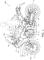
- FIG. 1 is a left side view of the straddled vehicle 100.
- FIG. 2 is a front view of the straddled vehicle 100.
- the straddled vehicle 100 includes a vehicle body frame 2, a steering device 3, a front wheel 4, a rear wheel 5, an engine 6, a fuel tank 7, a knee grip member 8, a seat 9, steps 10, and a vehicle body cover 11.
- connection is not limited to direct connection and encompasses indirect connection. Besides, the term “connection” is not limited to a condition that separate members are fixed to each other and encompasses a condition that a plurality of portions in an integrated member continue to each other.
- the fuel tank 7 is disposed behind the head pipe 12.
- the fuel tank 7 is disposed above the engine 6 and the main frame 13.
- the seat 9 is disposed behind the fuel tank 7.
- the seat 9 includes a seating surface 9a and lateral surfaces 9b.
- the seating surface 9a is provided on the upper surface of the seat 9.
- the seating surface 9a extends in both the back-and-forth direction and the vehicle width direction.
- the seating surface 9a is disposed upward and rearward of the knee grip portion 8a.
- the lateral surfaces 9b extend downward from both vehicle width-directional ends of the seating surface 9a.
- the vehicle body cover 11 is made of resin. As shown in FIG. 2 , the vehicle body cover 11 includes a front cover 21, exterior covers 22, and side covers 23.
- the front cover 21, the exterior covers 22 and the side covers 23 are respectively a pair of parts provided right and left.
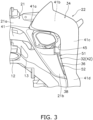
- FIG. 3 is a view of the vehicle body frame 2 and the exterior cover 22 seen from a front side of the vehicle.
- the front cover 21 is disposed below the position lights 17.
- the front cover 21 includes a middle portion 21a and lateral portions 21b.
- the middle portion 21a is disposed in the middle of the straddled vehicle 100 in the vehicle width direction.
- the middle portion 21a is disposed in front of the head pipe 12.
- the middle portion 21a supports the position lights 17.
- the lateral portions 21b are a pair of portions provided right and left.
- the lateral portions 21b extend rearward and downward from both vehicle width-directional ends of the middle portion 21a.
- the rear end of each lateral portion 21b is located on an outer side than the front end thereof in the vehicle width direction. In other words, the lateral portions 21b extend downward and outward in the vehicle width direction from both vehicle width-directional ends of the middle portion 21a in a vehicle front view.
- the inner panel 32 is fixed to the front cover 21 and side cover 23. As shown in FIG. 5 , the inner panel 32 includes a first panel 41, a second panel 42, and a wall portion 43.
- the second panel 42 is disposed behind the lateral portion 21b with a slight gap in the back-and-forth direction from the lateral portion 21b.
- the second panel 42 is disposed to continue to a portion of the lateral portion 21b in the back-and-forth direction.
- the second panel 42 is shaped to recess inward in the vehicle width direction.
- the second panel 42 is disposed on an inner side than the second extending portion 41c in the vehicle width direction.
- a downforce generated when the traveling wind hits the aero-stabilizing plates 51 and 52, is not enough to affect traveling of the straddled vehicle 100 and is absorbed by the resin deflection of the exterior cover 22; hence, the downforce does not act on the straddled vehicle 100.
- the aero-stabilizing plates 51 and 52 are at least partially exposed from the outer panel 34 in the vehicle side view.
- front ends 51c and 52c of the aero-stabilizing plates 51 and 52 are covered with the outer panel 34 in the vehicle side view.
- Rear ends 51d and 52d of the aero-stabilizing plates 51 and 52 are exposed from the outer panel 34 in the vehicle side view.
- the aero-stabilizing plates 51 and 52 may be entirely covered with the outer panel 34 in the vehicle side view.
- traveling wind, flowing through the traveling wind pathway 38 is directed to the knee grip portion 8a by the aero-stabilizing plates 51 and 52, whereby the traveling wind, flowing through the traveling wind pathway 38, hits the upper surface of the thigh of the rider so as to generate a downforce.
- the straddled vehicle 100 is configured such that the downforce acts on the vehicle body not by the aero-stabilizing plates 51 and 52 per se but through the rider.
- the aero-stabilizing plates 51 and 52 are provided for directing the traveling wind, flowing through the traveling wind pathway 38, to the knee grip portion 8a; hence, the downforce is almost not generated at the aero-stabilizing plates 51 and 52.
- the aero-stabilizing plates 51 and 52 have a flat plate, and the aero-stabilizing plates 51 and 52 per se do not generate enough downforce to affect traveling of the straddled vehicle 100. Because of this, increase in size of, and complexity in shape of, the aero-stabilizing plates 51 and 52 can be inhibited compared to a configuration that a downforce is generated at the aero-stabilizing plates 51 and 52 per se. Furthermore, necessity to enhance the strength and/or the stiffness of the aero-stabilizing plates 51 and 52 are lessened; hence, the aero-stabilizing plates 51 and 52 can be made in a quite simple and compact structure. As a result, a downforce can be generated in the straddled vehicle 100 with the simple structure.
- the knee grip member 8 is integrated with the fuel tank 7; alternatively, the knee grip member 8 may be separated from the fuel tank 7.
- the tank cover may be provided with the knee grip portion 8a on the lateral surfaces of the tank cover.
Landscapes
- Engineering & Computer Science (AREA)
- Mechanical Engineering (AREA)
- Automatic Cycles, And Cycles In General (AREA)
Abstract
Description
- The present invention relates to a straddled vehicle.
- There has been conventionally known a type of straddled vehicle with a structure whereby a downforce acts on a vehicle body. For example, a straddled vehicle disclosed in PTL 1 includes a traveling wind pathway, provided in a side cowl, and an aero-stabilizing member. The aero-stabilizing member is made in shape of a wing or fin and generates a downforce that acts on a vehicle body by traveling wind flowing through the traveling wind pathway.
- PTL1: Publication of
Japan Patent No. 6663949 - In attempt to generate a downforce enough to affect traveling of a vehicle by the aero-stabilizing member per se, the aero-stabilizing member is required to be enlarged to some extent and is also made complicated in shape. Furthermore, the aero-stabilizing member is also required to be enhanced in strength and/or stiffness. To cope with the above, in PTL 1, an inner cowl and the aero-stabilizing member are provided as components separated from each other; then, the aero-stabilizing member is fixed to the inner cowl by inserting the aero-stabilizing member through a through hole provided in the inner cowl. Besides, the aero-stabilizing member is provided with a reinforcing wall so as to be enhanced in strength and/or stiffness. Moreover, in order to generate a downforce, the aero-stabilizing member has a curved shape to protrude downward.
- As described above, in attempt to generate a downforce enough to affect traveling of the vehicle by the aero-stabilizing member per se, the shape of the aero-stabilizing member becomes more complex and the size of the aero-stabilizing member becomes larger.
- It is an object of the present invention to generate a downforce in a straddled vehicle with a simple structure.
- A straddled vehicle according to an aspect of the present invention includes a vehicle body frame, a fuel tank, a seat, a knee grip member, a step, an exterior cover, and an aero-stabilizing plate. The vehicle body frame includes a head pipe. The fuel tank is disposed behind the head pipe. The seat is disposed behind the fuel tank. The knee grip member is disposed behind the head pipe. The knee grip member includes a knee grip portion disposed forward and downward of the seat and is sandwiched by right and left knees of a rider. The step, on which a foot of the rider is put, is disposed rearward and downward of the knee grip portion. The exterior cover is disposed lateral to the head pipe. The exterior cover includes an inner panel, an outer panel, and a traveling wind pathway. The outer panel is disposed outside the inner panel in a vehicle width direction. The traveling wind pathway is formed between the inner panel and the outer panel to cause traveling wind coming from ahead to flow therethrough. The aero-stabilizing plate directs the traveling wind flowing through the traveling wind pathway to the knee grip portion. The aero-stabilizing plate, has a flat plate shape, is integrally molded with the inner panel and protrudes outward from the inner panel in the vehicle width direction to be supported by the inner panel in a cantilevered manner.
- In the straddled vehicle according to the present aspect, the traveling wind, flowing through the traveling wind pathway, is directed to the knee grip portion by the aero-stabilizing plate, whereby the traveling wind, flowing through the traveling wind pathway, hits the upper surface of the thigh of the rider so as to generate a downforce. In other words, the straddled vehicle according to the present aspect is configured such that the downforce acts on the vehicle body not by the aero-stabilizing plate per se but through the rider. The aero-stabilizing plate is provided for directing the traveling wind, flowing through the traveling wind pathway, to the knee grip portion; hence, a downforce is almost not generated at the aero-stabilizing plate.
- In detail, the aero-stabilizing plate has a flat plate shape, and the aero-stabilizing
plates - Besides, an effect of inhibiting a lift from acting on the rider can be obtained; hence, the rider is enabled to easily keep a riding style in high-speed traveling or so forth, whereby the rider is enhanced in comfortableness. Moreover, the rider becomes likely to feel a sense of unity with the vehicle body. Furthermore, the aero-stabilizing plate is made in shape of a flat plate not in shape of a wing or fin; hence, traveling wind can be accurately led to the vicinity of the thigh of the rider by the aero-stabilizing plate. Furthermore, the aero-stabilizing plate is supported by the inner panel in a cantilevered manner; hence, the aero-stabilizing plate can be disposed on a vehicle inner side than that supported by the outer panel in a cantilevered manner. In other words, the aero-stabilizing plate can be disposed in a closer position to the thigh of the rider than that supported by the outer panel in a cantilevered manner; hence, the traveling wind becomes likely to be led to the vicinity of the thigh of the rider by the aero-stabilizing plate.
- At least a portion of the aero-stabilizing plate may be exposed from the outer panel in a vehicle side view. In this case, it is easy to secure a length and/or an area of the aero-stabilizing plate required for causing the traveling wind to hit the vicinity of the thigh of the rider.
- A rear end of the aero-stabilizing plate may be located on a vehicle upper side than a lower end of the knee grip portion. In this case, the traveling wind becomes more likely to be led to the vicinity of the thigh of the rider by the aero-stabilizing plate.
- The rear end of the aero-stabilizing plate may be located on an upper side than a front end of the aero-stabilizing plate. In this case, the traveling wind becomes more likely to be led to the vicinity of the thigh of the rider by the aero-stabilizing plate.
- The exterior cover may further include an inlet for introducing the traveling wind to the traveling wind pathway. The rear end of the aero-stabilizing plate may be located on a lower side than an upper end of the inlet. In this case, the traveling wind becomes more likely to be led to the vicinity of the thigh of the rider by the aero-stabilizing plate.
- The knee grip member may be a fuel tank. In this case, since the fuel tank also serves as the knee grip member, reduction in number of components can be made.
- The aero-stabilizing plate may include a first aero-stabilizing plate and a second aero-stabilizing plate disposed below the first aero-stabilizing plate. The second aero-stabilizing plate may protrude more outward than the first aero-stabilizing plate in the vehicle width direction. In this case, the traveling wind becomes more likely to be led to the vicinity of the thigh of the rider by the aero-stabilizing plate.
- According to the present invention, a downforce can be generated in a straddled vehicle with a simple structure.
-
-
FIG. 1 is a left side view of a straddled vehicle. -
FIG. 2 is a front view of the straddled vehicle. -
FIG. 3 is a view of a vehicle body frame and an exterior cover seen from a front side of the vehicle. -
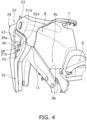
FIG. 4 is a view of the exterior cover and the surroundings thereof seen from a left rear side of the vehicle. -
FIG. 5 is a left side view of an inner panel. -
FIG. 6 is a partial left side view of the exterior cover. -
FIG. 7 is a partial cross-sectional view taken along line VII-VII inFIG. 5 . -
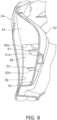
FIG. 8 is a cross-sectional view taken along line VIII-VIII inFIG. 6 . -
FIG. 9 is a partial left side view of the straddled vehicle. - An embodiment of a straddled vehicle according to an aspect of the present invention will be explained with reference to drawings. It should be noted that in the following explanation, terms indicating such directions as "back and forth", "up and down", and "right and left" are explained based on directions seen from a rider in operation of a straddled
vehicle 100. Therefore, a right-and-left direction is synonymous with a vehicle width direction. Besides, the term "outer side in a vehicle width direction" means a side far from the center of the straddled vehicle in the vehicle width direction. The term "inner side in the vehicle width direction" means a side near to the center of the straddled vehicle in the vehicle width direction. -
FIG. 1 is a left side view of the straddledvehicle 100.FIG. 2 is a front view of the straddledvehicle 100. The straddledvehicle 100 includes a vehicle body frame 2, asteering device 3, afront wheel 4, arear wheel 5, anengine 6, afuel tank 7, aknee grip member 8, aseat 9, steps 10, and avehicle body cover 11. - The vehicle body frame 2 includes a
head pipe 12 and amain frame 13. Thehead pipe 12 extends forward and downward. Thehead pipe 12 is disposed in the center of the straddledvehicle 100 in the vehicle width direction. - The
main frame 13 is connected at the front end thereof to thehead pipe 12. Themain frame 13 is composed of a pair of parts provided right and left. Themain frame 13 branches from thehead pipe 12 to the left and right and extends rearward from thehead pipe 12. It should be noted that the term "connection" is not limited to direct connection and encompasses indirect connection. Besides, the term "connection" is not limited to a condition that separate members are fixed to each other and encompasses a condition that a plurality of portions in an integrated member continue to each other. - The
steering device 3 is rotatably supported by thehead pipe 12. Thesteering device 3 includes afront fork 14 and ahandle portion 15. Thefront fork 14 is composed of a pair of parts provided right and left. Thefront fork 14 extends forward and downward. Thefront fork 14 is connected at alower end 14a thereof to thefront wheel 4. Thehandle portion 15 is connected to thefront fork 14. Thehandle portion 15 includes ahandlebar 15a extending in the right-and-left direction. Thehandlebar 15a is provided with grips on both ends thereof. Awind shield 16 is disposed in front of thehandle portion 15. Position lights 17 are disposed below thewind shield 16. - The
front wheel 4 is rotatably supported by thefront fork 14. Therear wheel 5 is rotatably supported by aswing arm 18 disposed behind theengine 6. - The
engine 6 is supported by the vehicle body frame 2. Theengine 6 is disposed below themain frame 13. - The
fuel tank 7 is disposed behind thehead pipe 12. Thefuel tank 7 is disposed above theengine 6 and themain frame 13. - The
knee grip member 8 is disposed behind thehead pipe 12. In the present embodiment, theknee grip member 8 is integrated with thefuel tank 7. In other words, thefuel tank 7 also serves as theknee grip member 8. Theknee grip member 8 includes aknee grip portion 8a. Theknee grip portion 8a is sandwiched by the right and left knees of the rider during traveling of the straddledvehicle 100. Besides, when the rider grips theknee grip portion 8a by the knees, an inner side of a thigh near the knee of the rider contact theknee grip portion 8a. - The
knee grip portion 8a is provided on the right and left lateral surfaces of thefuel tank 7. For example, theknee grip portion 8a is shaped to be recessed from the outer side to the inner side in the vehicle width direction. Theknee grip portion 8a is disposed forward and downward of theseat 9. Because of this, when the rider grips theknee grip portion 8a by the knees, the thigh of the rider is kept tilted forward and downward with respect to a horizontal direction in a vehicle side view. Preferably, theknee grip portion 8a is disposed in an overlapping position with a virtual line V connecting thelower end 14a of thefront fork 14 and theseat 9 in the vehicle side view. - The
seat 9 is disposed behind thefuel tank 7. Theseat 9 includes aseating surface 9a andlateral surfaces 9b. Theseating surface 9a is provided on the upper surface of theseat 9. Theseating surface 9a extends in both the back-and-forth direction and the vehicle width direction. Theseating surface 9a is disposed upward and rearward of theknee grip portion 8a. The lateral surfaces 9b extend downward from both vehicle width-directional ends of theseating surface 9a. - The
steps 10 are components on which the rider puts the feet. Thesteps 10 are a pair of components provided right and left. Thesteps 10 have a rod shape and extend in the vehicle width direction. Thesteps 10 are disposed rearward and downward of theknee grip portion 8a. Thesteps 10 are disposed below theseat 9. When the rider grips theknee grip portion 8a by the knees, a lower thigh of the rider is kept tilted rearward and downward with respect to the horizontal direction in the vehicle side view. - The
vehicle body cover 11 is made of resin. As shown inFIG. 2 , thevehicle body cover 11 includes afront cover 21, exterior covers 22, and side covers 23. Thefront cover 21, the exterior covers 22 and the side covers 23 are respectively a pair of parts provided right and left. -
FIG. 3 is a view of the vehicle body frame 2 and theexterior cover 22 seen from a front side of the vehicle. Thefront cover 21 is disposed below the position lights 17. Thefront cover 21 includes amiddle portion 21a andlateral portions 21b. Themiddle portion 21a is disposed in the middle of the straddledvehicle 100 in the vehicle width direction. Themiddle portion 21a is disposed in front of thehead pipe 12. Themiddle portion 21a supports the position lights 17. Thelateral portions 21b are a pair of portions provided right and left. Thelateral portions 21b extend rearward and downward from both vehicle width-directional ends of themiddle portion 21a. The rear end of eachlateral portion 21b is located on an outer side than the front end thereof in the vehicle width direction. In other words, thelateral portions 21b extend downward and outward in the vehicle width direction from both vehicle width-directional ends of themiddle portion 21a in a vehicle front view. - The exterior covers 22 are disposed lateral to the
head pipe 12. The exterior covers 22 cover thehead pipe 12 from outside in the vehicle width direction. Eachexterior cover 22 includes aninner panel 32, anouter panel 34, aninlet 36, and a travelingwind pathway 38. -
FIG. 4 is a view of theexterior cover 22 and the surroundings thereof seen from a left rear side of the vehicle.FIG. 5 is a left side view of theinner panel 32.FIG. 6 is a partial left side view of theexterior cover 22.FIG. 7 is a partial cross-sectional view taken along line VII-VII inFIG. 5 .FIG. 8 is a cross-sectional view taken along line VIII-VIII inFIG. 6 .FIG. 9 is a partial left side view of the straddled vehicle. - The
inner panel 32 is fixed to thefront cover 21 andside cover 23. As shown inFIG. 5 , theinner panel 32 includes afirst panel 41, asecond panel 42, and awall portion 43. - The
first panel 41 is disposed lateral tolateral portion 21b of thefront cover 21. Thefirst panel 41 covers thelateral portion 21b of thefront cover 21 from outside in the vehicle width direction such that an opening 45 (seeFIG. 3 ), into which traveling wind coming from ahead flows, is formed therebetween. - As shown in
FIGS. 3 and5 , thefirst panel 41 includes anupper portion 41a, a first extendingportion 41b, a second extendingportion 41c, and alower portion 41d. Theupper portion 41a extends in the back-and-forth direction. Theupper portion 41a is fixed to themiddle portion 21a of thefront cover 21. The first extendingportion 41b extends outward from theupper portion 41a in the vehicle width direction. The second extendingportion 41c extends downward and rearward from the first extendingportion 41b so as to laterally cover thelateral portion 21b. The second extendingportion 41c is separated from thelateral portion 21b in the vehicle width direction. Thelower portion 41d is fixed to the lower end of thelateral portion 21b of thefront cover 21. Thelower portion 41d is located on an outer side than theupper portion 41a in the vehicle width direction. Thelower portion 41d extends downward and rearward from the second extendingportion 41c. - As shown in
FIGS. 3 and4 , thesecond panel 42 is disposed behind thelateral portion 21b with a slight gap in the back-and-forth direction from thelateral portion 21b. Thesecond panel 42 is disposed to continue to a portion of thelateral portion 21b in the back-and-forth direction. As shown inFIG. 4 , thesecond panel 42 is shaped to recess inward in the vehicle width direction. As shown inFIG. 7 , thesecond panel 42 is disposed on an inner side than the second extendingportion 41c in the vehicle width direction. - As shown in
FIG. 5 , thesecond panel 42 is disposed behind the second extendingportion 41c in the vehicle side view. Anupper end 42a of thesecond panel 42 extends rearward from the vicinity of a boundary between theupper portion 41a and the first extendingportion 41b of thefirst panel 41 in the vehicle side view. Alower end 42b of thesecond panel 42 is connected to thelower portion 41d. Thelower end 42b of thesecond panel 42 extends rearward from the lower end of the second extendingportion 41c in the vehicle side view. Theupper end 42a of thesecond panel 42 extends more rearward than thelower end 42b of thesecond panel 42. - The
wall portion 43 extends in the vehicle width direction between the second extendingportion 41c and thesecond panel 42. Thewall portion 43 is connected to the second extendingportion 41c and thesecond panel 42. The lower end of thewall portion 43 is located on an upper side than the lower end of the second extendingportion 41c and thelower end 42b of thesecond panel 42. - The
outer panel 34 is disposed outside theinner panel 32 in the vehicle width direction. Theouter panel 34 is fixed to theinner panel 32 so as to cover theinner panel 32 from outside in the vehicle width direction. In detail, as shown inFIGS. 3 and6 , theouter panel 34 covers the entirety of thefirst panel 41. As shown inFIG. 8 , theouter panel 34 covers at least a portion of thesecond panel 42 from outside in the vehicle width direction so as to form the travelingwind pathway 38 therebetween. In the present embodiment, theouter panel 34 covers a portion of thesecond panel 42 that is adjacent to the second extendingportion 41c of thefirst panel 41. Thesecond panel 42 is exposed at an approximately rear half thereof without being covered with theouter panel 34. - The
inlet 36 introduces the traveling wind coming from ahead through theopening 45 to the travelingwind pathway 38. Theinlet 36 is an opening penetrating in the back-and-forth direction. As shown inFIG. 3 , theinlet 36 partially overlaps with theopening 45 in the vehicle front view. Theinlet 36 partially overlaps with theouter panel 34 in the vehicle front view. As shown inFIG. 4 , anupper end 36a of theinlet 36 is located on an upper side than the lower end of thehead pipe 12. In the present embodiment, theinlet 36 is formed between thefirst panel 41 and thesecond panel 42. Theinlet 36 is formed below thewall portion 43. Theupper end 36a of theinlet 36 corresponds to the lower end of thewall portion 43. Theinlet 36 extends from the lower end of thewall portion 43 to thelower end 42b of thesecond panel 42. Theupper end 36a of theinlet 36 is located on a lower side than theseat 9. As shown inFIG. 4 , theupper end 36a of theinlet 36 is located upward of alower end 8b of theknee grip portion 8a. The lower end of theinlet 36 is located on a lower side than theknee grip portion 8a. The lower end of theinlet 36 is located on an upper side than theengine 6. - The traveling
wind pathway 38 causes traveling wind, coming from ahead, to flow therethrough. The traveling wind, coming from ahead, flows into theopening 45 and is then introduced to the travelingwind pathway 38 from theinlet 36. The traveling wind introduced from theinlet 36 passes through the travelingwind pathway 38 and flows rearward. In detail, after passing through the travelingwind pathway 38, the traveling wind passes through a lateral side of thefuel tank 7. In other words, after passing through the travelingwind pathway 38, the traveling wind passes through a lateral side of theknee grip portion 8a. - The traveling
wind pathway 38 is formed between theinner panel 32 and theouter panel 34. As shown inFIGS. 4 and8 , the travelingwind pathway 38 is formed in a region between thesecond panel 42 and theouter panel 34. As shown inFIG. 9 , the travelingwind pathway 38 overlaps with theknee grip portion 8a in the back-and-forth direction in the vehicle side view. - The straddled
vehicle 100 includes aero-stabilizingplates plates wind pathway 38. The aero-stabilizingplates wind pathway 38. The aero-stabilizingplates wind pathway 38, to theknee grip portion 8a. In detail, as shown with arrow inFIG. 9 , the traveling wind, flowing through the travelingwind pathway 38, is directed to theknee grip portion 8a by the aero-stabilizingplates plates - As shown in
FIG. 8 , the aero-stabilizingplates plates inner panel 32. The aero-stabilizingplates inner panel 32 in the vehicle width direction to be supported by theinner panel 32 in a cantilevered manner. The aero-stabilizingplates outer panel 34 in the vehicle width direction without being connected to theouter panel 34. The aero-stabilizingplates - The aero-stabilizing
plates vehicle 100, is not generated at the aero-stabilizingplates FIGS. 7 and8 ,upper surfaces lower surfaces plates plates plates lower surfaces plates exterior cover 22. In other words, a downforce, generated when the traveling wind hits the aero-stabilizingplates vehicle 100 and is absorbed by the resin deflection of theexterior cover 22; hence, the downforce does not act on the straddledvehicle 100. - As shown in
FIG. 6 , the aero-stabilizingplates outer panel 34 in the vehicle side view. In detail, front ends 51c and 52c of the aero-stabilizingplates outer panel 34 in the vehicle side view. Rear ends 51d and 52d of the aero-stabilizingplates outer panel 34 in the vehicle side view. It should be noted that the aero-stabilizingplates outer panel 34 in the vehicle side view. - In the aero-stabilizing
plates plates FIG. 4 , the rear ends 51d and 52d of the aero-stabilizingplates lower end 8b of theknee grip portion 8a. The rear ends 51d and 52d of the aero-stabilizingplates upper end 36a of theinlet 36. - The aero-stabilizing
plates plates second panel 42. The aero-stabilizingplates inlet 36 and adjacent to theinlet 36. The aero-stabilizingplates inlet 36 in the vehicle front view. The aero-stabilizingplate 52 is disposed below the aero-stabilizingplate 51. As shown inFIGS. 7 and8 , the aero-stabilizingplate 52 protrudes more outward than the aero-stabilizingplate 51 in the vehicle width direction. The aero-stabilizingplate 51 is an exemplary first aero-stabilizing plate, whereas the aero-stabilizingplate 52 is an exemplary second aero-stabilizing plate. - As shown in
FIGS. 1 and4 , each side cover 23 is disposed between eachexterior cover 22 and thefuel tank 7. Each side cover 23 is disposed above thesecond panel 42 of theinner panel 32 and themain frame 13. Each side cover 23 is disposed to continue at a rear portion thereof to the lateral surface of thefuel tank 7. - In the straddled
vehicle 100 according to the present aspect, traveling wind, flowing through the travelingwind pathway 38, is directed to theknee grip portion 8a by the aero-stabilizingplates wind pathway 38, hits the upper surface of the thigh of the rider so as to generate a downforce. In other words, the straddledvehicle 100 is configured such that the downforce acts on the vehicle body not by the aero-stabilizingplates plates wind pathway 38, to theknee grip portion 8a; hence, the downforce is almost not generated at the aero-stabilizingplates - In detail, as described above, the aero-stabilizing
plates plates vehicle 100. Because of this, increase in size of, and complexity in shape of, the aero-stabilizingplates plates plates plates vehicle 100 with the simple structure. - Besides, an effect of inhibiting a lift from acting on the rider can be obtained; hence, the rider is enabled to easily keep a riding style in high-speed traveling or so forth, whereby the rider is enhanced in comfortableness. Moreover, the rider becomes likely to feel a sense of unity with the vehicle body. Furthermore, the aero-stabilizing
plates plates plates inner panel 32 disposed on a vehicle inner side than theouter panel 34, whereby the traveling wind becomes likely to be led to the vicinity of the thigh of the rider by the aero-stabilizingplates - One embodiment of the present invention has been explained above. However, the present invention is not limited to the embodiment described above, and a variety of changes can be made without departing from the gist of the present invention.
- In the embodiment described above, the
knee grip member 8 is integrated with thefuel tank 7; alternatively, theknee grip member 8 may be separated from thefuel tank 7. Incidentally, when thefuel tank 7 includes a tank cover, the tank cover may be provided with theknee grip portion 8a on the lateral surfaces of the tank cover. - In the embodiment described above, the
inner panel 32 and theouter panel 34 are separated from each other; alternatively, theinner panel 32 and theouter panel 34 may be integrated with each other. - The aero-stabilizing
plates plates inner panel 32 may be provided with only either at least one aero-stabilizingplate 51 or at least one aero-stabilizingplate 52. - According to the present invention, a downforce can be generated in a straddled vehicle with a simple structure.
-
- 2
- Vehicle body frame
- 7
- Fuel tank
- 8
- Knee grip member
- 8a
- Knee grip portion
- 8b
- Lower end of knee grip portion
- 9
- Seat
- 10
- Step
- 22
- Exterior cover
- 32
- Inner panel
- 34
- Outer panel
- 36
- Inlet
- 36a
- Upper end of inlet
- 38
- Traveling wind pathway
- 51
- Aero-stabilizing plate (exemplary first aero-stabilizing plate)
- 52
- Aero-stabilizing plate (exemplary second aero-stabilizing plate)
- 51a, 52a
- Front end of aero-stabilizing plate
- 51d, 52d
- Rear end of aero-stabilizing plate
- 100
- Straddled vehicle
Claims (7)
- A straddled vehicle comprising:a vehicle body frame including a head pipe;a fuel tank disposed behind the head pipe;a seat disposed behind the fuel tank;a knee grip member disposed behind the head pipe, the knee grip member including a knee grip portion disposed forward and downward of the seat, the knee grip portion sandwiched by right and left knees of a rider;a step on which a foot of the rider is put, the step disposed rearward and downward of the knee grip portion;an exterior cover disposed lateral to the head pipe, the exterior cover including an inner panel, an outer panel, and a traveling wind pathway, the outer panel disposed outside the inner panel in a vehicle width direction, the traveling wind pathway formed between the inner panel and the outer panel to cause traveling wind coming from ahead to flow therethrough; andan aero-stabilizing plate directing the traveling wind flowing through the traveling wind pathway to the knee grip portion, whereinthe aero-stabilizing plate has a flat plate shape, the aero-stabilizing plate integrally molded with the inner panel, the aero-stabilizing plate protruding outward from the inner panel in the vehicle width direction to be supported by the inner panel in a cantilevered manner.
- The straddled vehicle according to claim 1, wherein at least a portion of the aero-stabilizing plate is exposed from the outer panel in a vehicle side view.
- The straddled vehicle according to claim 1 or 2, wherein a rear end of the aero-stabilizing plate is located on a vehicle upper side than a lower end of the knee grip portion.
- The straddled vehicle according to any one of claims 1 to 3, wherein a rear end of the aero-stabilizing plate is located on an upper side than a front end of the aero-stabilizing plate.
- The straddled vehicle according to claim 4, whereinthe exterior cover further includes an inlet for introducing the traveling wind to the traveling wind pathway, andthe rear end of the aero-stabilizing plate is located on a lower side than an upper end of the inlet.
- The straddled vehicle according to any one of claims 1 to 5, wherein the knee grip member is the fuel tank.
- The straddled vehicle according to any one of claims 1 to 6, whereinthe aero-stabilizing plate includes a first aero-stabilizing plate and a second aero-stabilizing plate disposed below the first aero-stabilizing plate, andthe second aero-stabilizing plate protrudes more outward than the first aero-stabilizing plate in the vehicle width direction.
Applications Claiming Priority (2)
| Application Number | Priority Date | Filing Date | Title |
|---|---|---|---|
| JP2020157663A JP2023165040A (en) | 2020-09-18 | 2020-09-18 | saddle type vehicle |
| PCT/JP2021/033783 WO2022059679A1 (en) | 2020-09-18 | 2021-09-14 | Straddled vehicle |
Publications (2)
| Publication Number | Publication Date |
|---|---|
| EP4215430A1 true EP4215430A1 (en) | 2023-07-26 |
| EP4215430A4 EP4215430A4 (en) | 2024-10-30 |
Family
ID=80776028
Family Applications (1)
| Application Number | Title | Priority Date | Filing Date |
|---|---|---|---|
| EP21869365.3A Withdrawn EP4215430A4 (en) | 2020-09-18 | 2021-09-14 | Straddled vehicle |
Country Status (3)
| Country | Link |
|---|---|
| EP (1) | EP4215430A4 (en) |
| JP (1) | JP2023165040A (en) |
| WO (1) | WO2022059679A1 (en) |
Families Citing this family (2)
| Publication number | Priority date | Publication date | Assignee | Title |
|---|---|---|---|---|
| JP7529721B2 (en) | 2022-06-03 | 2024-08-06 | 本田技研工業株式会社 | Saddle-type vehicle |
| JP7621322B2 (en) | 2022-12-01 | 2025-01-24 | 本田技研工業株式会社 | vehicle |
Family Cites Families (13)
| Publication number | Priority date | Publication date | Assignee | Title |
|---|---|---|---|---|
| JPS62105628A (en) | 1985-11-01 | 1987-05-16 | 東芝タンガロイ株式会社 | High-tenacity coated cemented carbide and manufacture thereof |
| JPH10305791A (en) * | 1997-05-07 | 1998-11-17 | Suzuki Motor Corp | Motorcycle cowling structure |
| JP4527148B2 (en) * | 2007-12-30 | 2010-08-18 | 本田技研工業株式会社 | Motorcycle |
| JP5248237B2 (en) * | 2008-08-12 | 2013-07-31 | 本田技研工業株式会社 | Vehicle front structure |
| JP5771100B2 (en) * | 2011-09-06 | 2015-08-26 | 川崎重工業株式会社 | Saddle riding vehicle |
| JP5930376B2 (en) * | 2012-02-16 | 2016-06-08 | 本田技研工業株式会社 | Saddle riding vehicle |
| JP2014210485A (en) * | 2013-04-18 | 2014-11-13 | ヤマハ発動機株式会社 | Two-wheeled motor vehicle |
| JP5852618B2 (en) * | 2013-09-20 | 2016-02-03 | 本田技研工業株式会社 | Saddle-type vehicle with shroud |
| JP2015123765A (en) * | 2013-12-25 | 2015-07-06 | ヤマハ発動機株式会社 | Motorcycle |
| JP6244607B2 (en) * | 2014-07-23 | 2017-12-13 | 本田技研工業株式会社 | Shroud structure of saddle riding type vehicle |
| JP6312339B2 (en) * | 2016-03-08 | 2018-04-18 | 本田技研工業株式会社 | Vehicle side cover |
| JP6679535B2 (en) * | 2017-05-31 | 2020-04-15 | 本田技研工業株式会社 | Saddle type vehicle |
| JP6806747B2 (en) * | 2018-09-28 | 2021-01-06 | 本田技研工業株式会社 | Cowl structure of saddle-riding vehicle |
-
2020
- 2020-09-18 JP JP2020157663A patent/JP2023165040A/en active Pending
-
2021
- 2021-09-14 WO PCT/JP2021/033783 patent/WO2022059679A1/en not_active Ceased
- 2021-09-14 EP EP21869365.3A patent/EP4215430A4/en not_active Withdrawn
Also Published As
| Publication number | Publication date |
|---|---|
| EP4215430A4 (en) | 2024-10-30 |
| JP2023165040A (en) | 2023-11-15 |
| WO2022059679A1 (en) | 2022-03-24 |
Similar Documents
| Publication | Publication Date | Title |
|---|---|---|
| JP5202075B2 (en) | Wind guide structure of scooter type vehicle | |
| EP3418168B1 (en) | Saddle riding vehicle | |
| JP6184103B2 (en) | Saddle riding | |
| EP2530001B1 (en) | Riding-type vehicle | |
| EP3028930B1 (en) | Motorcycle body cover structure | |
| JP6432252B2 (en) | Saddle-type vehicle cowl | |
| JP2013052831A (en) | Straddle-type vehicle | |
| JP2014210485A (en) | Two-wheeled motor vehicle | |
| EP2889207B1 (en) | Motorcycle | |
| BR102016001020B1 (en) | SIDE COVER STRUCTURE OF VEHICLE TYPE TO MOUNT ON SADDLE | |
| EP2540603B1 (en) | Saddle type vehicle | |
| TWI478846B (en) | Straddle type vehicle | |
| EP2481657B1 (en) | Saddle-ride type vehicle | |
| WO2022059679A1 (en) | Straddled vehicle | |
| EP3964434A1 (en) | Side cowl | |
| JP6003477B2 (en) | Handle cover device for motorcycle | |
| JP6000995B2 (en) | Radiator shroud structure | |
| JP5852618B2 (en) | Saddle-type vehicle with shroud | |
| EP3889014B1 (en) | Straddled vehicle | |
| CN110325434B (en) | Saddle-ride type vehicle | |
| JP7383127B2 (en) | Windshield structure for saddle-type vehicles | |
| JP5865882B2 (en) | Reserve tank arrangement structure for motorcycles | |
| JP5738475B2 (en) | Front structure of saddle-ride type vehicle | |
| JPWO2018146881A1 (en) | Saddle riding | |
| EP2783957A1 (en) | Saddle type vehicle |
Legal Events
| Date | Code | Title | Description |
|---|---|---|---|
| STAA | Information on the status of an ep patent application or granted ep patent |
Free format text: STATUS: THE INTERNATIONAL PUBLICATION HAS BEEN MADE |
|
| PUAI | Public reference made under article 153(3) epc to a published international application that has entered the european phase |
Free format text: ORIGINAL CODE: 0009012 |
|
| STAA | Information on the status of an ep patent application or granted ep patent |
Free format text: STATUS: REQUEST FOR EXAMINATION WAS MADE |
|
| 17P | Request for examination filed |
Effective date: 20221213 |
|
| AK | Designated contracting states |
Kind code of ref document: A1 Designated state(s): AL AT BE BG CH CY CZ DE DK EE ES FI FR GB GR HR HU IE IS IT LI LT LU LV MC MK MT NL NO PL PT RO RS SE SI SK SM TR |
|
| DAV | Request for validation of the european patent (deleted) | ||
| DAX | Request for extension of the european patent (deleted) | ||
| A4 | Supplementary search report drawn up and despatched |
Effective date: 20241001 |
|
| RIC1 | Information provided on ipc code assigned before grant |
Ipc: B62K 11/04 20060101ALI20240925BHEP Ipc: B62J 35/00 20060101ALI20240925BHEP Ipc: B62J 17/06 20060101ALI20240925BHEP Ipc: B62J 25/02 20200101ALI20240925BHEP Ipc: B62J 23/00 20060101ALI20240925BHEP Ipc: B62J 17/10 20200101AFI20240925BHEP |
|
| STAA | Information on the status of an ep patent application or granted ep patent |
Free format text: STATUS: EXAMINATION IS IN PROGRESS |
|
| 17Q | First examination report despatched |
Effective date: 20250610 |
|
| STAA | Information on the status of an ep patent application or granted ep patent |
Free format text: STATUS: THE APPLICATION HAS BEEN WITHDRAWN |
|
| 18W | Application withdrawn |
Effective date: 20251008 |