EP4213255A1 - Electrode assembly manufacturing apparatus comprising ultrasound cutter, and electrode assembly manufacturing method using same - Google Patents
Electrode assembly manufacturing apparatus comprising ultrasound cutter, and electrode assembly manufacturing method using same Download PDFInfo
- Publication number
- EP4213255A1 EP4213255A1 EP21867182.4A EP21867182A EP4213255A1 EP 4213255 A1 EP4213255 A1 EP 4213255A1 EP 21867182 A EP21867182 A EP 21867182A EP 4213255 A1 EP4213255 A1 EP 4213255A1
- Authority
- EP
- European Patent Office
- Prior art keywords
- electrode
- unit
- cutting
- ultrasonic cutter
- assembly manufacturing
- Prior art date
- Legal status (The legal status is an assumption and is not a legal conclusion. Google has not performed a legal analysis and makes no representation as to the accuracy of the status listed.)
- Pending
Links
Images





Classifications
-
- B—PERFORMING OPERATIONS; TRANSPORTING
- B26—HAND CUTTING TOOLS; CUTTING; SEVERING
- B26F—PERFORATING; PUNCHING; CUTTING-OUT; STAMPING-OUT; SEVERING BY MEANS OTHER THAN CUTTING
- B26F1/00—Perforating; Punching; Cutting-out; Stamping-out; Apparatus therefor
- B26F1/38—Cutting-out; Stamping-out
- B26F1/44—Cutters therefor; Dies therefor
-
- B—PERFORMING OPERATIONS; TRANSPORTING
- B26—HAND CUTTING TOOLS; CUTTING; SEVERING
- B26D—CUTTING; DETAILS COMMON TO MACHINES FOR PERFORATING, PUNCHING, CUTTING-OUT, STAMPING-OUT OR SEVERING
- B26D7/00—Details of apparatus for cutting, cutting-out, stamping-out, punching, perforating, or severing by means other than cutting
- B26D7/08—Means for treating work or cutting member to facilitate cutting
- B26D7/086—Means for treating work or cutting member to facilitate cutting by vibrating, e.g. ultrasonically
-
- B—PERFORMING OPERATIONS; TRANSPORTING
- B26—HAND CUTTING TOOLS; CUTTING; SEVERING
- B26D—CUTTING; DETAILS COMMON TO MACHINES FOR PERFORATING, PUNCHING, CUTTING-OUT, STAMPING-OUT OR SEVERING
- B26D7/00—Details of apparatus for cutting, cutting-out, stamping-out, punching, perforating, or severing by means other than cutting
- B26D7/08—Means for treating work or cutting member to facilitate cutting
-
- H—ELECTRICITY
- H01—ELECTRIC ELEMENTS
- H01M—PROCESSES OR MEANS, e.g. BATTERIES, FOR THE DIRECT CONVERSION OF CHEMICAL ENERGY INTO ELECTRICAL ENERGY
- H01M10/00—Secondary cells; Manufacture thereof
- H01M10/04—Construction or manufacture in general
-
- H—ELECTRICITY
- H01—ELECTRIC ELEMENTS
- H01M—PROCESSES OR MEANS, e.g. BATTERIES, FOR THE DIRECT CONVERSION OF CHEMICAL ENERGY INTO ELECTRICAL ENERGY
- H01M10/00—Secondary cells; Manufacture thereof
- H01M10/04—Construction or manufacture in general
- H01M10/0404—Machines for assembling batteries
-
- H—ELECTRICITY
- H01—ELECTRIC ELEMENTS
- H01M—PROCESSES OR MEANS, e.g. BATTERIES, FOR THE DIRECT CONVERSION OF CHEMICAL ENERGY INTO ELECTRICAL ENERGY
- H01M10/00—Secondary cells; Manufacture thereof
- H01M10/04—Construction or manufacture in general
- H01M10/0413—Large-sized flat cells or batteries for motive or stationary systems with plate-like electrodes
-
- H—ELECTRICITY
- H01—ELECTRIC ELEMENTS
- H01M—PROCESSES OR MEANS, e.g. BATTERIES, FOR THE DIRECT CONVERSION OF CHEMICAL ENERGY INTO ELECTRICAL ENERGY
- H01M10/00—Secondary cells; Manufacture thereof
- H01M10/04—Construction or manufacture in general
- H01M10/0436—Small-sized flat cells or batteries for portable equipment
-
- H—ELECTRICITY
- H01—ELECTRIC ELEMENTS
- H01M—PROCESSES OR MEANS, e.g. BATTERIES, FOR THE DIRECT CONVERSION OF CHEMICAL ENERGY INTO ELECTRICAL ENERGY
- H01M10/00—Secondary cells; Manufacture thereof
- H01M10/04—Construction or manufacture in general
- H01M10/049—Processes for forming or storing electrodes in the battery container
-
- H—ELECTRICITY
- H01—ELECTRIC ELEMENTS
- H01M—PROCESSES OR MEANS, e.g. BATTERIES, FOR THE DIRECT CONVERSION OF CHEMICAL ENERGY INTO ELECTRICAL ENERGY
- H01M10/00—Secondary cells; Manufacture thereof
- H01M10/05—Accumulators with non-aqueous electrolyte
- H01M10/058—Construction or manufacture
- H01M10/0585—Construction or manufacture of accumulators having only flat construction elements, i.e. flat positive electrodes, flat negative electrodes and flat separators
-
- H—ELECTRICITY
- H01—ELECTRIC ELEMENTS
- H01M—PROCESSES OR MEANS, e.g. BATTERIES, FOR THE DIRECT CONVERSION OF CHEMICAL ENERGY INTO ELECTRICAL ENERGY
- H01M4/00—Electrodes
- H01M4/02—Electrodes composed of, or comprising, active material
- H01M4/04—Processes of manufacture in general
-
- H—ELECTRICITY
- H01—ELECTRIC ELEMENTS
- H01M—PROCESSES OR MEANS, e.g. BATTERIES, FOR THE DIRECT CONVERSION OF CHEMICAL ENERGY INTO ELECTRICAL ENERGY
- H01M4/00—Electrodes
- H01M4/02—Electrodes composed of, or comprising, active material
- H01M4/13—Electrodes for accumulators with non-aqueous electrolyte, e.g. for lithium-accumulators; Processes of manufacture thereof
- H01M4/139—Processes of manufacture
-
- H—ELECTRICITY
- H01—ELECTRIC ELEMENTS
- H01M—PROCESSES OR MEANS, e.g. BATTERIES, FOR THE DIRECT CONVERSION OF CHEMICAL ENERGY INTO ELECTRICAL ENERGY
- H01M50/00—Constructional details or processes of manufacture of the non-active parts of electrochemical cells other than fuel cells, e.g. hybrid cells
- H01M50/40—Separators; Membranes; Diaphragms; Spacing elements inside cells
- H01M50/46—Separators, membranes or diaphragms characterised by their combination with electrodes
-
- H—ELECTRICITY
- H01—ELECTRIC ELEMENTS
- H01M—PROCESSES OR MEANS, e.g. BATTERIES, FOR THE DIRECT CONVERSION OF CHEMICAL ENERGY INTO ELECTRICAL ENERGY
- H01M50/00—Constructional details or processes of manufacture of the non-active parts of electrochemical cells other than fuel cells, e.g. hybrid cells
- H01M50/50—Current conducting connections for cells or batteries
- H01M50/531—Electrode connections inside a battery casing
-
- Y—GENERAL TAGGING OF NEW TECHNOLOGICAL DEVELOPMENTS; GENERAL TAGGING OF CROSS-SECTIONAL TECHNOLOGIES SPANNING OVER SEVERAL SECTIONS OF THE IPC; TECHNICAL SUBJECTS COVERED BY FORMER USPC CROSS-REFERENCE ART COLLECTIONS [XRACs] AND DIGESTS
- Y02—TECHNOLOGIES OR APPLICATIONS FOR MITIGATION OR ADAPTATION AGAINST CLIMATE CHANGE
- Y02E—REDUCTION OF GREENHOUSE GAS [GHG] EMISSIONS, RELATED TO ENERGY GENERATION, TRANSMISSION OR DISTRIBUTION
- Y02E60/00—Enabling technologies; Technologies with a potential or indirect contribution to GHG emissions mitigation
- Y02E60/10—Energy storage using batteries
-
- Y—GENERAL TAGGING OF NEW TECHNOLOGICAL DEVELOPMENTS; GENERAL TAGGING OF CROSS-SECTIONAL TECHNOLOGIES SPANNING OVER SEVERAL SECTIONS OF THE IPC; TECHNICAL SUBJECTS COVERED BY FORMER USPC CROSS-REFERENCE ART COLLECTIONS [XRACs] AND DIGESTS
- Y02—TECHNOLOGIES OR APPLICATIONS FOR MITIGATION OR ADAPTATION AGAINST CLIMATE CHANGE
- Y02P—CLIMATE CHANGE MITIGATION TECHNOLOGIES IN THE PRODUCTION OR PROCESSING OF GOODS
- Y02P70/00—Climate change mitigation technologies in the production process for final industrial or consumer products
- Y02P70/50—Manufacturing or production processes characterised by the final manufactured product
Definitions
- the electrode assembly is formed by stacking a positive electrode and a negative electrode such that a separator is interposed therebetween, and the positive electrode and the negative electrode are manufactured through a process of forming an electrode tab at each of a positive electrode sheet and a negative electrode sheet and a process of cutting each of the positive electrode sheet and the negative electrode sheet into a unit electrode.
- the cutting line of the cutting edge of the ultrasonic cutter may be formed so as to correspond to the outer periphery of the unit electrode.
- step (b) and step (c) may be simultaneously performed.
- the length of the cutting edge in the y-axis direction is not uniform. That is, cutting lines 236, 246, and 256 of the cutting edge are not formed in a uniform plane.
- the recess may be formed so as to have a slit shape or a shape in which the size of the recess is gradually increased from the inside to the outside of the electrode sheet, although the shape of the recess is not particularly restricted. Specifically, a V-shaped recess may be formed.
- an electrode obtained by cutting the electrode sheet using the ultrasonic cutter and an electrode obtained by cutting the electrode sheet using the press cutter are compared with each other as follows.
Landscapes
- Engineering & Computer Science (AREA)
- Chemical & Material Sciences (AREA)
- Chemical Kinetics & Catalysis (AREA)
- General Chemical & Material Sciences (AREA)
- Electrochemistry (AREA)
- Manufacturing & Machinery (AREA)
- Mechanical Engineering (AREA)
- Life Sciences & Earth Sciences (AREA)
- Forests & Forestry (AREA)
- Materials Engineering (AREA)
- Connection Of Batteries Or Terminals (AREA)
- Battery Electrode And Active Subsutance (AREA)
- Secondary Cells (AREA)
Abstract
Description
- This application claims the benefit of priority to
Korean Patent Application No. 2020-0117858 filed on September 14, 2020 - The present invention relates to an electrode assembly manufacturing apparatus including an ultrasonic cutter and an electrode assembly manufacturing method using the same. More particularly, the present invention relates to an electrode assembly manufacturing apparatus including an ultrasonic cutter capable of cutting an electrode mixture coating portion as well as an electrode mixture non-coating portion in order to form an electrode tab at an electrode sheet and an electrode assembly manufacturing method using the same.
- A secondary battery, which is capable of being repeatedly charged and discharged, has an advantage in that lifespan of a battery cell is long, and is used in a form in which the secondary battery is detachably attached to a device or is built in a device. The kinds of devices using the secondary battery as an energy source have increased.
- In particular, a lithium secondary battery, which is charged and discharged as the result of movement of lithium ions, has been used not only in the field of a small-sized battery cell, which is used for mobile devices or small-sized electronic products, but also in the field of a medium- or large-sized battery pack, which is used as an energy source of an electric vehicle or a power storage system that requires high output and high voltage, since the lithium secondary battery has advantages of high energy density and high charge voltage.
- Based on the shape of a battery case, the lithium secondary battery is classified as a cylindrical secondary battery having an electrode assembly mounted in a cylindrical metal can, a prismatic secondary battery having an electrode assembly mounted in a prismatic metal can, or a pouch-shaped secondary battery having an electrode assembly mounted in a pouch-shaped case made of an aluminum laminate sheet.
- The electrode assembly is formed by stacking a positive electrode and a negative electrode such that a separator is interposed therebetween, and the positive electrode and the negative electrode are manufactured through a process of forming an electrode tab at each of a positive electrode sheet and a negative electrode sheet and a process of cutting each of the positive electrode sheet and the negative electrode sheet into a unit electrode.
- Conventionally, a method of removing the remaining part of a non-coating portion of the electrode sheet excluding the electrode tab by punching is used to form the electrode tab.
- Specifically, a press cutter including an upper cutter and a lower cutter is placed on the electrode sheet, and the electrode sheet is notched by punching using the upper cutter to form the electrode tab. In the case in which the press cutter including the upper cutter and the lower cutter is used, however, the distance between the upper cutter and the lower cutter must be maintained at 0. As a result, much time is taken to maintain the press cutter. Furthermore, an electrode mixture layer may be easily cracked and the electrode mixture layer may be separated from the electrode sheet by pressure applied to the electrode sheet at the time of punching.
- In addition, a burr may be generated on the cut section of an electrode sheet foil, or the cut section of the electrode sheet foil may be deformed, whereby quality of the cut section of the electrode sheet foil may be deteriorated.
- In addition, since vibration is generated during a punching process using the press cutter, the electrode sheet having the electrode tab formed thereat by notching is wound in the form of a roll and the wound electrode sheet is conveyed to a lamination process line in order to perform a lamination process. Since the notching process and the lamination process must be separately performed, as described above, it is necessary to secure a wide space necessary for electrode assembly production facilities, and it is difficult to automate the entire process for manufacturing the electrode assembly.
- In connection therewith, Patent Document 1 discloses an ultrasonic cutting device configured to cut a portion of a precursor of a secondary battery including a plurality of stacked power generation elements, each of which includes a positive electrode having a positive electrode protrusion for terminal connection, a separator, and a negative electrode having a negative electrode protrusion for terminal connection, e.g. a stack of the positive electrode protrusion and the negative electrode protrusion.
- The ultrasonic cutting device of Patent Document 1 cuts the positive electrode protrusion and the negative electrode protrusion in the state in which the power generation elements are stacked. However, a method of cutting a positive electrode and a negative electrode from an electrode sheet is not provided, and the ultrasonic cutting device cuts only non-coating portions of the positive electrode and the negative electrode.
- Therefore, there is a need for an electrode sheet cutter capable of preventing separation of an electrode mixture layer and deformation of an electrode sheet foil at the time of cutting an electrode mixture coating portion.
- (Patent Document 1)
Japanese Patent Application Publication No. 2018-09465 (2018.06.21 - The present invention has been made in view of the above problems, and it is an object of the present invention to provide an electrode assembly manufacturing apparatus capable of reducing a facility space necessary to manufacture an electrode assembly while preventing deformation of an electrode sheet foil and damage to an electrode mixture coating portion during a process of cutting an electrode sheet having a step formed due to the electrode mixture coating portion and an electrode assembly manufacturing method using the same.
- In order to accomplish the above object, an electrode assembly manufacturing apparatus according to the present invention includes an electrode sheet supply unit configured to supply an electrode sheet having an electrode mixture coating portion and an electrode mixture non-coating portion formed thereon, a cutting unit disposed at the rear of the electrode sheet supply unit, the cutting unit being configured to form an electrode tab at the electrode sheet, and a lamination unit disposed at the rear of the electrode sheet supply unit, the lamination unit being configured to laminate a positive electrode and a negative electrode stacked with a separator interposed between the positive and the negative electrodes, wherein the cutting unit includes a die configured to support the electrode sheet and an ultrasonic cutter spaced apart from the die, the ultrasonic cutter being configured to form the electrode tab, a cutting line of a cutting edge of the ultrasonic cutter is formed so as to correspond to an outer periphery of a unit electrode in a direction in which the electrode tab is formed, and the cutting unit and the lamination unit are disposed on the same process line such that a continuous process is performed.
- In the electrode assembly manufacturing apparatus according to the present invention, the ultrasonic cutter may further include an auxiliary cutting edge configured to form a recess configured to guide unit electrode cutting.
- The electrode assembly manufacturing apparatus according to the present invention may further include an electrode formation unit disposed between the cutting unit and the lamination unit, the electrode formation unit being configured to cut the electrode sheet in order to manufacture the unit electrode.
- In the electrode assembly manufacturing apparatus according to the present invention, the cutting line of the cutting edge of the ultrasonic cutter may be formed so as to correspond to the outer periphery of the unit electrode.
- In the electrode assembly manufacturing apparatus according to the present invention, the ultrasonic cutter may be configured to cut the electrode mixture coating portion.
- In the electrode assembly manufacturing apparatus according to the present invention, the cutting line of the cutting edge of the ultrasonic cutter may be formed in a uniform plane.
- In the electrode assembly manufacturing apparatus according to the present invention, an inspection member may be coupled to the ultrasonic cutter.
- In addition, the present invention provides an electrode assembly manufacturing method using the electrode assembly manufacturing apparatus.
- Specifically, the electrode assembly manufacturing method may include (a) conveying an electrode sheet to the cutting unit, (b) forming the electrode tab using the ultrasonic cutter, (c) cutting the electrode sheet into a unit electrode, and (d) laminating the positive electrode and the negative electrode with each other in the state in which the separator is interposed between the positive and the negative electrodes, wherein step (a) to step (d) may be performed on a continuous process line.
- In the electrode assembly manufacturing method according to the present invention, step (b) and step (c) may be simultaneously performed.
- In the electrode assembly manufacturing method according to the present invention, step (b) and step (c) may be sequentially performed, step (b) may be performed using a first ultrasonic cutter, and step (c) may be performed using a second ultrasonic cutter.
- In the electrode assembly manufacturing method according to the present invention, the vibration direction of the ultrasonic cutter may be a direction perpendicular to the electrode sheet.
- In the electrode assembly manufacturing method according to the present invention, step (b) may include forming a recess configured to guide unit electrode cutting.
- In the electrode assembly manufacturing method according to the present invention, step (b) may include pushing the cutting edge of the ultrasonic cutter once in the state in which the cutting edge of the ultrasonic cutter is placed on the outer surface of the electrode sheet to form the outer periphery of a unit electrode in the direction in which the electrode tab is formed.
- As is apparent from the above description, in the present invention, an ultrasonic cutter is used to form an electrode tab, whereby it is possible to prevent deformation of an electrode sheet foil or separation of an electrode mixture layer in the cut section of an electrode mixture coating portion as well as an electrode mixture non-coating portion.
- In addition, a cutting unit configured to form an electrode tab and a lamination unit are disposed on the same process line such that a continuous process can be performed, whereby it is possible to reduce space necessary for electrode assembly manufacturing facilities.
- Also, in the case in which an inspection member is coupled to the ultrasonic cutter, it is possible to inspect the cut section of an electrode sheet having an electrode tab formed thereat simultaneously with formation of the electrode tab.
-
-
FIG. 1 is a perspective view of an electrode assembly manufacturing apparatus according to a first embodiment. -
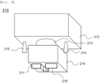
FIG. 2 is a perspective view of an ultrasonic cutter according to the present invention. -
FIG. 3 is an enlarged view of a cutting edge of the ultrasonic cutter. -
FIG. 4 is a plan view showing various shapes of the cutting edge. -
FIG. 5 is a partial enlarged view showing the portion of a positive electrode sheet at which a positive electrode tab is formed. -
FIG. 6 is a perspective view of a portion of an electrode assembly manufacturing apparatus according to a second embodiment. -
FIG. 7 is a perspective view of a portion of an electrode assembly manufacturing apparatus according to a third embodiment. -
FIG. 8 is a perspective view showing a cutting edge in an electrode assembly manufacturing apparatus according to a fourth embodiment. -
FIG. 9 is an enlarged view of the cut section of an electrode sheet cut using a press cutter. -
FIG. 10 is a plan view of the electrode sheet cut using the press cutter. -
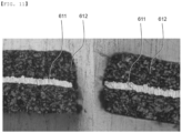
FIG. 11 is an enlarged view of the cut section of an electrode sheet cut using the ultrasonic cutter. -
FIG. 12 is a plan view of the electrode sheet cut using the ultrasonic cutter. -
FIG. 13 is a view showing comparison between sections of a positive electrode sheet having an insulative coating added thereto notched using a press and the ultrasonic cutter. -
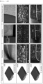
FIG. 14 is a view showing comparison between sections of a negative electrode sheet notched using the press, the ultrasonic cutter, and a laser. - Now, preferred embodiments of the present invention will be described in detail with reference to the accompanying drawings such that the preferred embodiments of the present invention can be easily implemented by a person having ordinary skill in the art to which the present invention pertains. In describing the principle of operation of the preferred embodiments of the present invention in detail, however, a detailed description of known functions and configurations incorporated herein will be omitted when the same may obscure the subject matter of the present invention.
- In addition, the same reference numbers will be used throughout the drawings to refer to parts that perform similar functions or operations. In the case in which one part is said to be connected to another part throughout the specification, not only may the one part be directly connected to the other part, but also, the one part may be indirectly connected to the other part via a further part. In addition, that a certain element is included does not mean that other elements are excluded, but means that such elements may be further included unless mentioned otherwise.
- In addition, a description to embody elements through limitation or addition may be applied to all inventions, unless particularly restricted, and does not limit a specific invention.
- Also, in the description of the invention and the claims of the present application, singular forms are intended to include plural forms unless mentioned otherwise.
- Also, in the description of the invention and the claims of the present application, "or" includes "and" unless mentioned otherwise. Therefore, "including A or B" means three cases, namely, the case including A, the case including B, and the case including A and B.
- Embodiments of the present invention will be described in detail with reference to the accompanying drawings.
-
FIG. 1 is a perspective view of an electrode assembly manufacturing apparatus according to a first embodiment, andFIG. 2 is a perspective view of an ultrasonic cutter according to the present invention. -
FIG. 1 shows a process of manufacturing a mono-cell configured to have a structure in which one positive electrode and one negative electrode are stacked in the state in which a separator is interposed therebetween. - Referring to
FIGS. 1 and2 , the electrodeassembly manufacturing apparatus 10 includes an electrodesheet supply unit 100 configured to supply an electrode sheet having an electrode mixture coating portion and an electrode mixture non-coating portion formed thereon; acutting unit 200 configured to form an electrode tab at the electrode sheet; and alamination unit 300 configured to laminate a positive electrode and a negative electrode stacked such that a separator is interposed therebetween. - The
cutting unit 200 includes anultrasonic cutter 210 and adie 220. An electrode tab is formed at an electrode sheet that moves above thedie 220 using theultrasonic cutter 210. - The
ultrasonic cutter 210 shown inFIG. 2 includes anoscillator 212 configured to generate ultrasonic waves, abooster 213 configured to amplify/reduce vibration energy generated by theoscillator 212, acutting edge 211 configured to cut an electrode sheet, and ahorn 214 configured to transmit the vibration energy from thebooster 213 to thecutting edge 211. - In a concrete example, the cutting speed of the
ultrasonic cutter 210 may be set to 200 m/s or less. The ultrasonic waves of the ultrasonic cutter may have an oscillation frequency of 15 kHz to 40 kHz and an amplitude of 10 um to 60 µm, which may be changed depending on the construction of the electrode sheet. - In the present invention, as described above, the ultrasonic cutter is used to form an electrode tab, and therefore damage to an electrode sheet due to vibration is less than in a conventional process of notching an electrode tab by punching using a press cutter.
- Also, in the case in which a conventional cutting unit cuts an electrode sheet using the press cutter, the distance between an upper cutter and a lower cutter must be maintained at 0, and therefore a micro-adjustment process for maintaining the distance between the upper cutter and the lower cutter is necessary. In the present invention, however, an electrode tab is formed by pushing the cutting edge of the ultrasonic cutter in the state in which the cutting edge is placed on the outer surface of the electrode sheet, and therefore a process of maintaining the distance between the upper cutter and the lower cutter is unnecessary, unlike the conventional art. Consequently, it is possible to save time necessary to maintain the distance between the upper cutter and the lower cutter in the conventional art.
- Meanwhile, vibration generated during the notching process using the press cutter is great in the conventional art. If the notching process and a lamination process of aligning and laminating a positive electrode and a negative electrode are performed on the same process line, therefore, vibration generated during the notching process may affect the lamination process. In the conventional art, therefore, a notching process line and a lamination process line are separately provided. Specifically, an electrode assembly is manufactured using a method of winding an electrode sheet that has undergone the notching process in the form of a roll, conveying the wound electrode sheet to the lamination process line, and performing the lamination process. Consequently, the notching process and the lamination process are discontinuously performed.
- In the present invention, however, the ultrasonic cutter, which generates little vibration, is used during a process of forming an electrode tab. Even though the cutting unit and the lamination unit are disposed on the same process line, therefore, vibration from the cutting unit hardly affects the lamination unit. In the present invention, therefore, the cutting unit and the lamination unit are disposed on the same process line, whereby the electrode tab formation process and the lamination process may be continuously performed.
- Consequently, a facility space necessary to manufacture an electrode assembly may be reduced. In addition, since time for conveying an electrode roll is unnecessary, it is possible to reduce time necessary to manufacture the electrode assembly and to automate the notching process and the lamination process.
- For example, in the case in which the notching process and the lamination process are continuously performed on the same process line, it is possible to reduce about 5% to 50% of time necessary when the notching process and the lamination process are discontinuously performed.
- In a concrete example, an
inspection member 215 is attached to theultrasonic cutter 210 ofFIG. 2 so as to face in a direction parallel to thecutting edge 211. A vision camera may be used as theinspection member 215. - In the case in which the press cutter is used in the conventional art, it is difficult to provide the inspection member at the press cutter due to impact generated during a cutting process. However, the present invention proposes a structure in which the inspection member is attached to the ultrasonic cutter, whereby it is possible to determine whether the shape of an electrode tab is normal simultaneously with cutting of an electrode sheet. Consequently, an electrode assembly manufacturing process may be shortened, whereby productivity may be improved.
- The electrode
sheet supply unit 100 ofFIG. 1 includes a positive electrode sheet supply unit configured to supply apositive electrode sheet 110 and a negative electrode sheet supply unit configured to supply anegative electrode sheet 120. - The
positive electrode sheet 110 is provided with a positive electrodemixture coating portion 111, in which opposite surfaces of a positiveelectrode sheet foil 113 are coated with a positive electrode mixture, and a positive electrodemixture non-coating portion 112, in which no positive electrode mixture is formed on the opposite surfaces of the positiveelectrode sheet foil 113 by coating. That is, the positive electrodemixture non-coating portion 112 is an exposed portion of the positiveelectrode sheet foil 113. - The description of the
positive electrode sheet 110 having the positive electrodemixture coating portion 111 and the positive electrodemixture non-coating portion 112, in which no positive electrode mixture is formed by coating, is equally applied to anegative electrode sheet 120 having a negative electrodemixture coating portion 121 and a negative electrodemixture non-coating portion 122, in which no negative electrode mixture is formed by coating. - Referring to
FIGS. 1 and2 , acutting line 216 of thecutting edge 211 of theultrasonic cutter 210 ofFIG. 2 is formed so as to correspond to the outer periphery of a unit electrode in a direction in which an electrode tab is formed. - When the
cutting edge 211 of the ultrasonic cutter is disposed at a position at which an electrode tab is to be formed and an electrode sheet is pressed using the ultrasonic cutter, therefore, the remaining part of the positive electrodemixture non-coating portion 112 excluding apositive electrode tab 114 is cut along the shape of thecutting line 216, whereby thepositive electrode tab 114 is formed, and the remaining part of the negative electrodemixture non-coating portion 122 excluding anegative electrode tab 124 is cut along the shape of thecutting line 216, whereby thenegative electrode tab 124 is formed. - An
electrode formation unit 400, which is configured to cut the positive electrode sheet having thepositive electrode tab 114 formed thereat in order to manufacture a unit positive electrode and which is configured to cut the negative electrode sheet having thenegative electrode tab 124 formed thereat in order to manufacture a unit negative electrode, is located at the rear of thecutting unit 200. That is, theelectrode formation unit 400 is disposed between the cuttingunit 200 and thelamination unit 300. - The unit positive electrode and the unit negative electrode mean a single positive electrode and a single negative electrode manufactured by cutting the positive electrode sheet and the negative electrode sheet at predetermined intervals. In this specification, the positive electrode is used as a meaning including the unit positive electrode, and the negative electrode is used as a meaning including the unit negative electrode.
- In the
electrode formation unit 400, acutter 410 configured to cut the electrode sheet may be a press cutter including an upper cutter and a lower cutter, or an ultrasonic cutter may be used. - In the case in which the ultrasonic cutter is used, it is possible to cut the electrode sheet such that damage to the electrode mixture layer and the electrode sheet foil is minimized.
- The unit positive electrodes and the unit negative electrodes cut by the electrode formation unit are conveyed to the
lamination unit 300 in a state of being attached to aseparator 150 so as to be spaced apart from each other by a predetermined distance. Apositive electrode 131 attached to theseparator 150 and anegative electrode 132 attached to theseparator 150 are laminated with each other while passing between a pair ofrollers 310 included in thelamination unit 300. Subsequently, a separator cutting process is performed, whereby a mono-cell having a structure in which the positive electrode, the separator, the negative electrode, and the separator are sequentially stacked is manufactured. - In a concrete example, an electrode assembly manufacturing method according to the present invention may include (a) a step of conveying an electrode sheet to the cutting unit, (b) a step of forming an electrode tab using the ultrasonic cutter, (c) a step of cutting the electrode sheet into a unit electrode, and (d) a step of laminating a positive electrode and a negative electrode with each other in the state in which a separator is interposed therebetween, wherein step (a) to step (d) may be performed on a continuous process line.
- As shown in
FIG. 1 , step (b) performed at thecutting unit 200 and step (c) performed at theelectrode formation unit 400 may be sequentially performed. In step (b), theultrasonic cutter 210 may be used as a first ultrasonic cutter. In step (c), thecutter 410 may be used as a second ultrasonic cutter. - The vibration direction of the
ultrasonic cutter 210 is a direction perpendicular to thepositive electrode sheet 110 and thenegative electrode sheet 120. Consequently, theultrasonic cutter 210 is moved in a direction perpendicular to the positive electrode sheet and the negative electrode sheet such that the movement direction of the ultrasonic cutter is identical to the vibration direction of the ultrasonic cutter. - In connection therewith,
FIG. 3 is an enlarged view of the cutting edge of the ultrasonic cutter. - Referring to
FIG. 3 , thecutting line 216 of thecutting edge 211 of the ultrasonic cutter is bent so as to correspond in shape to the outer periphery of a unit electrode at which an electrode tab is formed. - Referring to an enlarged sectional view of the cutting edge taken along line A-A', the end of the section of the cutting edge is formed in a V shape. Consequently, the cutting edge must be moved in a state of being perpendicular to the electrode sheet such that the electrode sheet is cut by the end of the cutting edge. In this case, contact between the cutting edge and the electrode sheet may be minimized, whereby friction therebetween may be minimized. If the cutting edge is moved in a state of being inclined relative to the electrode sheet, not perpendicular to the electrode sheet, in order to cut the electrode sheet, the electrode sheet may be burned due to friction generated as the result of contact between the V-shaped inclined surface of the end of the cutting edge and the electrode sheet.
- Meanwhile, the cutting line of the cutting edge of the ultrasonic cutter is formed in a uniform plane. That is, the length of the cutting edge in a y-axis direction is uniform over the entirety thereof.
- In connection therewith,
FIG. 4 is a plan view showing various shapes of the cutting edge. - Referring to (a) to (c) of
FIG. 4 , the length of the cutting edge in the y-axis direction is not uniform. That is, cutting lines 236, 246, and 256 of the cutting edge are not formed in a uniform plane. - In the case in which an electrode sheet is cut using the press cutter including the upper cutter and the lower cutter in the conventional art, the cutting edge having any of the above-mentioned shapes is used in order to increase cutting force. When the electrode sheet is cut using the cutting edges shown in (a) to (c) of
FIG. 4 , however, the cutting edges must be further moved by h1, h2, and h3 in the y-axis direction. - In contrast, the movement distance of the cutting edge used in the present invention in the y-axis direction is reduced by h1, h2, and h3, compared to the cutting edges shown in
FIG. 4 , and therefore it is possible to reduce time necessary to form the electrode tab, compared to the case in which the conventional press cutter is used. -
FIG. 5 is a partial enlarged view showing the portion of the positive electrode sheet at which the positive electrode tab is formed. - Referring to
FIG. 5 , the positive electrode sheet is cut such that anouter periphery 115 of the positive electrode is formed at the part of the positive electrode shifted toward the positive electrodemixture coating portion 111 by G based on aborder line 116 between the positive electrodemixture coating portion 111 and the positive electrodemixture non-coating portion 112. - That is, the ultrasonic cutter cuts not only the positive electrode
mixture non-coating portion 112, at which thepositive electrode tab 114 is formed, but also the positive electrodemixture coating portion 111. -
FIG. 6 is a perspective view of a portion of an electrode assembly manufacturing apparatus according to a second embodiment. - Referring to
FIG. 6 , apositive electrode sheet 110 supplied from an electrodesheet supply unit 100 is provided with a positive electrodemixture coating portion 111 and a positive electrodemixture non-coating portion 112, and apositive electrode tab 114 is formed at the positive electrodemixture non-coating portion 112 and a border between the positive electrodemixture coating portion 111 and the positive electrodemixture non-coating portion 112. - Two cutting
edges 211 of anultrasonic cutter 210 are continuously disposed, which is different fromFIG. 1 . The speed at which the positive electrode tab is formed may be increased in proportion to extension of thecutting edge 211. -
FIG. 7 is a perspective view of a portion of an electrode assembly manufacturing apparatus according to a third embodiment. - Referring to
FIG. 7 , the ultrasonic cutter further includes anauxiliary cutting edge 219, when compared toFIG. 1 . Theauxiliary cutting edge 219 is provided to form a recess configured to guide unit electrode cutting. A recess configured to indicate the position at which the electrode sheet is cut in order to manufacture a unit electrode may be formed. - The recess may be formed so as to have a slit shape or a shape in which the size of the recess is gradually increased from the inside to the outside of the electrode sheet, although the shape of the recess is not particularly restricted. Specifically, a V-shaped recess may be formed.
- Consequently, cutting for forming an electrode tab and cutting for forming a recess configured to guide unit electrode cutting may be simultaneously performed, whereby the manufacturing process may be shortened.
-
FIG. 8 is a perspective view showing a cutting edge in an electrode assembly manufacturing apparatus according to a fourth embodiment. - Referring to
FIG. 8 , acutting line 266 of thecutting edge 231 is formed in a shape corresponding to the outer periphery of apositive electrode 131. - When the cutting edge of
FIG. 8 is used, a step of forming an electrode tab using an ultrasonic cutter and a step of cutting an electrode sheet into a unit electrode may be simultaneously performed. Consequently, it is possible to separate apositive electrode 131 having a positive electrode tab formed thereat from a positive electrode sheet by pressing the electrode sheet once. Therefore, the separate electrode formation unit ofFIG. 1 is not necessary. - Consequently, it is possible to simplify the electrode assembly manufacturing process and to reduce manufacturing time.
- In order to determine whether an electrode sheet is damaged in the case in which the electrode assembly manufacturing apparatus according to the present invention is used, an electrode obtained by cutting the electrode sheet using the ultrasonic cutter and an electrode obtained by cutting the electrode sheet using the press cutter are compared with each other as follows.
-
FIG. 9 is an enlarged view of the cut section of an electrode sheet cut using the press cutter, andFIG. 10 is a plan view of the electrode sheet cut using the press cutter.FIG. 11 is an enlarged view of the cut section of an electrode sheet cut using the ultrasonic cutter, andFIG. 12 is a plan view of the electrode sheet cut using the ultrasonic cutter. - Referring to
FIGS. 9 and10 , it can be seen from the cut section of the electrode sheet cut using the press cutter shown inFIG. 9 that anelectrode sheet foil 511 was bent and anelectrode mixture layer 512 was separated from theelectrode sheet foil 511. In addition, it can be seen from a portion indicated by a dotted line inFIG. 10 that theelectrode mixture layer 512 was separated from theelectrode sheet foil 511. - Referring to
FIGS. 11 and12 using the ultrasonic cutter, it can be seen that both of anelectrode sheet foil 611 and anelectrode mixture layer 612 were not deformed at the cut section of the electrode sheet and that theelectrode mixture layer 612 was normally attached to theelectrode sheet foil 611. -
FIG. 13 is a view showing comparison between sections of a positive electrode sheet having an insulative coating added thereto notched using a press and the ultrasonic cutter. - Referring to
FIG. 13 , it can be seen that the insulative coating was separated from the positive electrode notched using the press, as shown in a circle indicated by a dotted line. However, it can be seen that the positive electrode notched using the ultrasonic cutter had a neat external appearance without separation of the insulative coating layer and that a smooth border line of the positive electrode mixture layer was maintained, i.e. the positive electrode mixture layer was stably attached to the positive electrode sheet foil. -
FIG. 14 is a view showing comparison between sections of a negative electrode sheet notched using the press, the ultrasonic cutter, and a laser. - Referring to
FIG. 14 , it can be seen that, when press notching was performed, an electrode tab was bent and a burr was generated on anelectrode sheet foil 711 in the cut section of the positive electrode sheet. It can be seen that, when laser notching was performed, anelectrode mixture layer 712 in the cut section of an electrode tab and the notching section were thermally deformed by heat from the laser. It can be seen that, when notching was performed using the ultrasonic cutter, theelectrode sheet foil 711 and theelectrode mixture layer 712 were not damaged in both the electrode tab and the notching section, theelectrode sheet foil 711 was not bent even in the cut section, and theelectrode mixture layer 712 was normally attached to theelectrode sheet foil 711. - In the case in which the ultrasonic cutter is used, as described above, the electrode mixture layer may remain stably attached to the electrode sheet foil, and generation of a burr on the cut section of the electrode sheet foil or the deformation of the cut section of the electrode sheet foil may be minimized.
- Those skilled in the art to which the present invention pertains will appreciate that various applications and modifications are possible within the category of the present invention based on the above description.
-
- 10:
- Electrode assembly manufacturing apparatus
- 100:
- Electrode sheet supply unit
- 110:
- Positive electrode sheet
- 111:
- Positive electrode mixture coating portion
- 112:
- Positive electrode mixture non-coating portion
- 113:
- Positive electrode sheet foil
- 114:
- Positive electrode tab
- 115:
- Outer periphery of positive electrode
- 116:
- Border line
- 120:
- Negative electrode sheet
- 121:
- Negative electrode mixture coating portion
- 122:
- Negative electrode mixture non-coating portion
- 124:
- Negative electrode tab
- 131:
- Positive electrode
- 132:
- Negative electrode
- 150:
- Separator
- 200:
- Cutting unit
- 210:
- Ultrasonic cutter
- 211, 231:
- Cutting edges
- 212:
- Oscillator
- 213:
- Booster
- 214:
- Horn
- 215:
- Inspection member
- 216, 236, 246, 256, 266:
- Cutting lines
- 219:
- Auxiliary cutting edge
- 220:
- Die
- 300:
- Lamination unit
- 310:
- Roller
- 400:
- Electrode formation unit
- 410:
- Cutter
- 511, 611, 711:
- Electrode sheet foils
- 512, 612, 712:
- Electrode mixture layers
- As is apparent from the above description, in the present invention, an ultrasonic cutter is used to form an electrode tab, whereby it is possible to prevent deformation of an electrode sheet foil or separation of an electrode mixture layer in the cut section of an electrode mixture coating portion as well as an electrode mixture non-coating portion.
- In addition, a cutting unit configured to form an electrode tab and a lamination unit are disposed on the same process line such that a continuous process can be performed, whereby it is possible to reduce space necessary for electrode assembly manufacturing facilities.
- Also, in the case in which an inspection member is coupled to the ultrasonic cutter, it is possible to inspect the cut section of an electrode sheet having an electrode tab formed thereat simultaneously with formation of the electrode tab.
Claims (13)
- An electrode assembly manufacturing apparatus comprising:an electrode sheet supply unit configured to supply an electrode sheet having an electrode mixture coating portion and an electrode mixture non-coating portion formed thereon;a cutting unit disposed at a rear of the electrode sheet supply unit, the cutting unit being configured to form an electrode tab at the electrode sheet; anda lamination unit disposed at a rear of the electrode sheet supply unit, the lamination unit being configured to laminate a positive electrode and a negative electrode stacked with a separator interposed between the positive and the negative electrodes,wherein the cutting unit comprises a die configured to support the electrode sheet and an ultrasonic cutter spaced apart from the die, the ultrasonic cutter being configured to form the electrode tab,wherein a cutting line of a cutting edge of the ultrasonic cutter is formed so as to correspond to an outer periphery of a unit electrode in a direction in which the electrode tab is formed, andwherein the cutting unit and the lamination unit are disposed on an identical process line such that a continuous process is performed.
- The electrode assembly manufacturing apparatus according to claim 1, wherein the ultrasonic cutter further comprises an auxiliary cutting edge configured to form a recess configured to guide unit electrode cutting.
- The electrode assembly manufacturing apparatus according to claim 1, further comprising an electrode formation unit disposed between the cutting unit and the lamination unit, the electrode formation unit being configured to cut the electrode sheet in order to manufacture the unit electrode.
- The electrode assembly manufacturing apparatus according to claim 1, wherein the cutting line of the cutting edge of the ultrasonic cutter is formed so as to correspond to the outer periphery of the unit electrode.
- The electrode assembly manufacturing apparatus according to claim 1, wherein the ultrasonic cutter is configured to cut the electrode mixture coating portion.
- The electrode assembly manufacturing apparatus according to claim 1, wherein the cutting line of the cutting edge of the ultrasonic cutter is formed in a uniform plane.
- The electrode assembly manufacturing apparatus according to claim 1, wherein an inspection member is coupled to the ultrasonic cutter.
- An electrode assembly manufacturing method using the electrode assembly manufacturing apparatus according to any one of claims 1 to 7, the electrode assembly manufacturing method comprising:(a) conveying an electrode sheet to the cutting unit;(b) forming the electrode tab using the ultrasonic cutter;(c) cutting the electrode sheet into a unit electrode; and(d) laminating the positive electrode and the negative electrode with each other in a state in which the separator is interposed between the positive and the negative electrodes,wherein step (a) to step (d) are performed on a continuous process line.
- The electrode assembly manufacturing method according to claim 8, wherein step (b) and step (c) are simultaneously performed.
- The electrode assembly manufacturing method according to claim 8, whereinstep (b) and step (c) are sequentially performed,step (b) is performed using a first ultrasonic cutter, andstep (c) is performed using a second ultrasonic cutter.
- The electrode assembly manufacturing method according to claim 8, wherein a vibration direction of the ultrasonic cutter is a direction perpendicular to the electrode sheet.
- The electrode assembly manufacturing method according to claim 8, wherein step (b) comprises forming a recess configured to guide unit electrode cutting.
- The electrode assembly manufacturing method according to claim 8, wherein step (b) includes pushing the cutting edge of the ultrasonic cutter once in a state in which the cutting edge of the ultrasonic cutter is placed on an outer surface of the electrode sheet to form an outer periphery of the unit electrode in a direction in which the electrode tab is formed.
Applications Claiming Priority (2)
| Application Number | Priority Date | Filing Date | Title |
|---|---|---|---|
| KR1020200117858A KR102846515B1 (en) | 2020-09-14 | 2020-09-14 | Electrode Assembly Manufacturing Apparatus Including Ultrasonic Cutting Machine and Electrode Assembly Manufacturing Method Using the Same |
| PCT/KR2021/012408 WO2022055317A1 (en) | 2020-09-14 | 2021-09-13 | Electrode assembly manufacturing apparatus comprising ultrasound cutter, and electrode assembly manufacturing method using same |
Publications (2)
| Publication Number | Publication Date |
|---|---|
| EP4213255A1 true EP4213255A1 (en) | 2023-07-19 |
| EP4213255A4 EP4213255A4 (en) | 2024-07-17 |
Family
ID=80630382
Family Applications (1)
| Application Number | Title | Priority Date | Filing Date |
|---|---|---|---|
| EP21867182.4A Pending EP4213255A4 (en) | 2020-09-14 | 2021-09-13 | DEVICE FOR PRODUCING AN ELECTRODE ARRANGEMENT WITH AN ULTRASONIC CUTTER AND METHOD FOR PRODUCING AN ELECTRODE ARRANGEMENT THEREOF |
Country Status (6)
| Country | Link |
|---|---|
| US (1) | US12390947B2 (en) |
| EP (1) | EP4213255A4 (en) |
| JP (1) | JP7540630B2 (en) |
| KR (1) | KR102846515B1 (en) |
| CN (1) | CN115336061B (en) |
| WO (1) | WO2022055317A1 (en) |
Cited By (1)
| Publication number | Priority date | Publication date | Assignee | Title |
|---|---|---|---|---|
| KR102759917B1 (en) * | 2024-06-13 | 2025-01-31 | 주식회사 엠플러스 | Secondary battery ultra-high speed dual cutting system and secondary battery ultra-high speed dual cutting method |
Families Citing this family (10)
| Publication number | Priority date | Publication date | Assignee | Title |
|---|---|---|---|---|
| KR102846416B1 (en) * | 2021-01-08 | 2025-08-14 | 주식회사 엘지에너지솔루션 | Welding Device, Welding Method Using the Same, and Electrode Assembly Manufactured by Welding Method |
| WO2023197108A1 (en) * | 2022-04-11 | 2023-10-19 | 宁德时代新能源科技股份有限公司 | Method and device for correcting positions of tabs of electrode assembly |
| KR20230154713A (en) * | 2022-05-02 | 2023-11-09 | 에스케이온 주식회사 | Electrode, electrode assembly and manufacturing method thereof |
| US20260031383A1 (en) * | 2022-07-22 | 2026-01-29 | Lg Energy Solution, Ltd. | Apparatus for Manufacturing Secondary Battery, Method for Manufacturing Secondary Battery Using the Same, and Secondary Battery Manufactured Using the Same |
| EP4560823B1 (en) * | 2022-07-22 | 2026-04-29 | LG Energy Solution, Ltd. | Apparatus for manufacturing secondary battery, method for manufacturing secondary battery using the same, and secondary battery manufactured using the same |
| KR102876046B1 (en) | 2023-11-27 | 2025-10-23 | 주식회사 엘지에너지솔루션 | Processing method of lithium metal for negative electrode of electrode assembly |
| WO2025147150A1 (en) | 2024-01-03 | 2025-07-10 | 주식회사 엘지에너지솔루션 | Anode for lithium metal battery, electrode assembly for lithium metal battery, and lithium metal battery |
| KR20250113089A (en) | 2024-01-18 | 2025-07-25 | 주식회사 엘지에너지솔루션 | Manufacturing equipment of electrode |
| KR102704054B1 (en) * | 2024-02-05 | 2024-09-09 | 디에이치 주식회사 | Hybrid notching device and notching method for secondary battery electrodes |
| CN118682841A (en) * | 2024-08-23 | 2024-09-24 | 精箔(洛阳)新材料科技有限公司 | A high-precision battery foil cutting device |
Family Cites Families (25)
| Publication number | Priority date | Publication date | Assignee | Title |
|---|---|---|---|---|
| JP3334511B2 (en) | 1996-09-27 | 2002-10-15 | トヨタ自動車株式会社 | Cutting and welding method using ultrasonic cutter |
| JP3469488B2 (en) | 1999-01-21 | 2003-11-25 | 株式会社アルテクス | Ultrasonic vibration cutting device |
| KR100647199B1 (en) * | 2005-06-03 | 2006-11-23 | (주)해빛정보 | Ultrasonic Cutting Machine and Method |
| KR101108118B1 (en) | 2008-11-27 | 2012-01-31 | 주식회사 엠플러스 | Secondary Battery Manufacturing Method and Secondary Battery |
| CN103155226B (en) | 2010-10-15 | 2016-04-20 | A123系统有限责任公司 | Integral battery tab |
| JP2012199210A (en) | 2011-03-23 | 2012-10-18 | Ihi Corp | Production apparatus and production method of electrode laminate |
| JP2012240159A (en) * | 2011-05-19 | 2012-12-10 | Ihi Corp | Ultrasonic cutting device |
| KR101586121B1 (en) | 2013-09-30 | 2016-01-22 | 주식회사 엘지화학 | Lamination device including electrode guide |
| KR101729815B1 (en) | 2014-07-29 | 2017-04-24 | 주식회사 엘지화학 | Electrode assembly and radical cell for the same |
| KR20160048527A (en) | 2014-10-24 | 2016-05-04 | 주식회사 엘지화학 | A Cutting Method of Irregular Cell and the Irregular Cell Manufactured by The Same |
| KR101772418B1 (en) | 2015-02-03 | 2017-08-29 | 주식회사 엘지화학 | Method for Manufacturing Unit Electrode Comprising Insulating Layer |
| US10665864B2 (en) | 2016-01-19 | 2020-05-26 | Lg Chem, Ltd. | Electrode assembly and method for manufacturing same |
| JP6765881B2 (en) | 2016-07-12 | 2020-10-07 | 日立オートモティブシステムズ阪神株式会社 | Ignition coil for internal combustion engine |
| JP6821242B2 (en) | 2016-07-12 | 2021-01-27 | 日本車輌製造株式会社 | Engine generator |
| JP6815185B2 (en) | 2016-12-14 | 2021-01-20 | 株式会社エンビジョンAescジャパン | Ultrasonic cutting device |
| JP6544397B2 (en) * | 2017-08-29 | 2019-07-17 | 株式会社アドウェルズ | Cutting device |
| DE102017218137A1 (en) * | 2017-10-11 | 2019-04-11 | Robert Bosch Gmbh | Method for producing an electrode arrangement, electrode arrangement and battery cell with such an electrode arrangement |
| WO2019088047A1 (en) * | 2017-10-30 | 2019-05-09 | 株式会社東芝 | Battery |
| KR102278998B1 (en) | 2017-12-26 | 2021-07-20 | 주식회사 엘지에너지솔루션 | Manufacturing system and manufacturing method of secondary battery |
| JP2019202520A (en) * | 2018-05-25 | 2019-11-28 | 株式会社豊田自動織機 | Joint device |
| CA3027620A1 (en) | 2018-12-13 | 2020-06-13 | Hydro-Quebec | Cutting of soft metals by ultrasonic assistance |
| KR102742818B1 (en) * | 2018-12-20 | 2024-12-13 | 주식회사 엘지에너지솔루션 | Method for Preparing Separator Integrated type Electrode and Electrode Assembly Comprising Electrode Manufactured Using the Same |
| JP7308647B2 (en) | 2019-04-04 | 2023-07-14 | 株式会社ディスコ | processing equipment |
| CN210308473U (en) | 2019-04-26 | 2020-04-14 | 惠州市三协精密有限公司 | Ultrasonic cutting device |
| CN110919750A (en) | 2019-12-10 | 2020-03-27 | 广东亿鑫丰智能装备股份有限公司 | One-step forming device and process for pole piece and pole ear fillet |
-
2020
- 2020-09-14 KR KR1020200117858A patent/KR102846515B1/en active Active
-
2021
- 2021-09-13 JP JP2022559436A patent/JP7540630B2/en active Active
- 2021-09-13 CN CN202180024671.XA patent/CN115336061B/en active Active
- 2021-09-13 WO PCT/KR2021/012408 patent/WO2022055317A1/en not_active Ceased
- 2021-09-13 US US18/005,015 patent/US12390947B2/en active Active
- 2021-09-13 EP EP21867182.4A patent/EP4213255A4/en active Pending
Cited By (2)
| Publication number | Priority date | Publication date | Assignee | Title |
|---|---|---|---|---|
| KR102759917B1 (en) * | 2024-06-13 | 2025-01-31 | 주식회사 엠플러스 | Secondary battery ultra-high speed dual cutting system and secondary battery ultra-high speed dual cutting method |
| WO2025258977A1 (en) * | 2024-06-13 | 2025-12-18 | 주식회사 엠플러스 | Ultra-high-speed dual cutting system for secondary battery and ultra-high-speed dual cutting method for secondary battery |
Also Published As
| Publication number | Publication date |
|---|---|
| KR20220035741A (en) | 2022-03-22 |
| KR102846515B1 (en) | 2025-08-18 |
| US20230330885A1 (en) | 2023-10-19 |
| CN115336061A (en) | 2022-11-11 |
| CN115336061B (en) | 2025-08-19 |
| US12390947B2 (en) | 2025-08-19 |
| JP7540630B2 (en) | 2024-08-27 |
| EP4213255A4 (en) | 2024-07-17 |
| WO2022055317A1 (en) | 2022-03-17 |
| JP2023519948A (en) | 2023-05-15 |
Similar Documents
| Publication | Publication Date | Title |
|---|---|---|
| US12390947B2 (en) | Electrode assembly manufacturing apparatus including ultrasonic cutter and method using the same | |
| US11217780B2 (en) | Method for manufacturing secondary battery and secondary battery using same | |
| KR101586121B1 (en) | Lamination device including electrode guide | |
| CN111527638B (en) | Method for manufacturing all-solid-state batteries | |
| US12051827B2 (en) | Electrode assembly configured such that pressure welding portions of electrode tab welding portions have different sizes and ultrasonic welding apparatus configured to manufacture the same | |
| EP3735110B1 (en) | Plasma generating apparatus for secondary battery | |
| CN113644230A (en) | Battery pole piece, battery and battery pole piece manufacturing method | |
| CN114079039B (en) | Negative electrode, electrode assembly and manufacturing method thereof, battery cell, battery pack, device including the same and measurement method | |
| EP3136466B1 (en) | Manufacture method of electrode assembly | |
| JP2021028896A (en) | Manufacturing method of power storage device | |
| JP2019102196A (en) | Manufacturing method of battery | |
| WO2013031889A1 (en) | Method for manufacturing cell electrode | |
| EP4631664A1 (en) | Ultrasonic welding device and welded structure | |
| JP2003297430A (en) | Method of manufacturing secondary battery and device for manufacturing secondary battery electrode | |
| EP4016723B1 (en) | Electrolyte injection device and electrolyte injection method using the same | |
| EP4184634B1 (en) | Cutting device and lamination equipment and method for secondary battery comprising same | |
| EP4086997A1 (en) | Method for manufacturing electrode including folding part and electrode sheet including folding part | |
| US20230142103A1 (en) | Method of Manufacturing Electrode Including Folding Portion and Electrode Sheet Including Folding Portion | |
| JP2005199381A (en) | Punching method and punching device | |
| US20230216018A1 (en) | Method and system for manufacturing electrode | |
| EP4113707B1 (en) | Manufacturing method of battery cell and pouch forming apparatus | |
| JP2017191728A (en) | Method of manufacturing electrode, and rotary die cutter | |
| EP4550512A1 (en) | Method for manufacturing electrode assembly with improved processability, and electrode assembly manufactured using same | |
| US20250128445A1 (en) | Secondary battery electrode notching apparatus | |
| EP4235888B1 (en) | Manufacturing device for electrode assembly and method using the same |
Legal Events
| Date | Code | Title | Description |
|---|---|---|---|
| STAA | Information on the status of an ep patent application or granted ep patent |
Free format text: STATUS: THE INTERNATIONAL PUBLICATION HAS BEEN MADE |
|
| PUAI | Public reference made under article 153(3) epc to a published international application that has entered the european phase |
Free format text: ORIGINAL CODE: 0009012 |
|
| STAA | Information on the status of an ep patent application or granted ep patent |
Free format text: STATUS: REQUEST FOR EXAMINATION WAS MADE |
|
| 17P | Request for examination filed |
Effective date: 20220922 |
|
| AK | Designated contracting states |
Kind code of ref document: A1 Designated state(s): AL AT BE BG CH CY CZ DE DK EE ES FI FR GB GR HR HU IE IS IT LI LT LU LV MC MK MT NL NO PL PT RO RS SE SI SK SM TR |
|
| DAV | Request for validation of the european patent (deleted) | ||
| DAX | Request for extension of the european patent (deleted) | ||
| A4 | Supplementary search report drawn up and despatched |
Effective date: 20240613 |
|
| RIC1 | Information provided on ipc code assigned before grant |
Ipc: H01M 50/46 20210101ALI20240607BHEP Ipc: H01M 10/0585 20100101ALI20240607BHEP Ipc: H01M 4/139 20100101ALI20240607BHEP Ipc: H01M 4/04 20060101ALI20240607BHEP Ipc: B26F 1/44 20060101ALI20240607BHEP Ipc: B26D 7/08 20060101ALI20240607BHEP Ipc: H01M 50/531 20210101ALI20240607BHEP Ipc: H01M 10/04 20060101AFI20240607BHEP |
|
| STAA | Information on the status of an ep patent application or granted ep patent |
Free format text: STATUS: EXAMINATION IS IN PROGRESS |
|
| 17Q | First examination report despatched |
Effective date: 20250711 |