EP4212944B1 - Optisches system und kopfmontierte anzeigevorrichtung - Google Patents
Optisches system und kopfmontierte anzeigevorrichtung Download PDFInfo
- Publication number
- EP4212944B1 EP4212944B1 EP21953029.2A EP21953029A EP4212944B1 EP 4212944 B1 EP4212944 B1 EP 4212944B1 EP 21953029 A EP21953029 A EP 21953029A EP 4212944 B1 EP4212944 B1 EP 4212944B1
- Authority
- EP
- European Patent Office
- Prior art keywords
- lens
- optical system
- present disclosure
- satisfies
- abs
- Prior art date
- Legal status (The legal status is an assumption and is not a legal conclusion. Google has not performed a legal analysis and makes no representation as to the accuracy of the status listed.)
- Active
Links
Images


Classifications
-
- G—PHYSICS
- G02—OPTICS
- G02B—OPTICAL ELEMENTS, SYSTEMS OR APPARATUS
- G02B1/00—Optical elements characterised by the material of which they are made; Optical coatings for optical elements
- G02B1/04—Optical elements characterised by the material of which they are made; Optical coatings for optical elements made of organic materials, e.g. plastics
- G02B1/041—Lenses
-
- G—PHYSICS
- G02—OPTICS
- G02B—OPTICAL ELEMENTS, SYSTEMS OR APPARATUS
- G02B13/00—Optical objectives specially designed for the purposes specified below
- G02B13/001—Miniaturised objectives for electronic devices, e.g. portable telephones, webcams, PDAs, small digital cameras
- G02B13/0015—Miniaturised objectives for electronic devices, e.g. portable telephones, webcams, PDAs, small digital cameras characterised by the lens design
- G02B13/002—Miniaturised objectives for electronic devices, e.g. portable telephones, webcams, PDAs, small digital cameras characterised by the lens design having at least one aspherical surface
- G02B13/0035—Miniaturised objectives for electronic devices, e.g. portable telephones, webcams, PDAs, small digital cameras characterised by the lens design having at least one aspherical surface having three lenses
-
- G—PHYSICS
- G02—OPTICS
- G02B—OPTICAL ELEMENTS, SYSTEMS OR APPARATUS
- G02B13/00—Optical objectives specially designed for the purposes specified below
- G02B13/18—Optical objectives specially designed for the purposes specified below with lenses having one or more non-spherical faces, e.g. for reducing geometrical aberration
-
- G—PHYSICS
- G02—OPTICS
- G02B—OPTICAL ELEMENTS, SYSTEMS OR APPARATUS
- G02B25/00—Eyepieces; Magnifying glasses
- G02B25/001—Eyepieces
-
- G—PHYSICS
- G02—OPTICS
- G02B—OPTICAL ELEMENTS, SYSTEMS OR APPARATUS
- G02B27/00—Optical systems or apparatus not provided for by any of the groups G02B1/00 - G02B26/00, G02B30/00
- G02B27/01—Head-up displays
- G02B27/017—Head mounted
- G02B27/0172—Head mounted characterised by optical features
-
- G—PHYSICS
- G02—OPTICS
- G02B—OPTICAL ELEMENTS, SYSTEMS OR APPARATUS
- G02B3/00—Simple or compound lenses
- G02B3/02—Simple or compound lenses with non-spherical faces
-
- G—PHYSICS
- G02—OPTICS
- G02B—OPTICAL ELEMENTS, SYSTEMS OR APPARATUS
- G02B3/00—Simple or compound lenses
- G02B3/02—Simple or compound lenses with non-spherical faces
- G02B3/08—Simple or compound lenses with non-spherical faces with discontinuous faces, e.g. Fresnel lens
-
- G—PHYSICS
- G02—OPTICS
- G02B—OPTICAL ELEMENTS, SYSTEMS OR APPARATUS
- G02B9/00—Optical objectives characterised both by the number of the components and their arrangements according to their sign, i.e. + or -
- G02B9/12—Optical objectives characterised both by the number of the components and their arrangements according to their sign, i.e. + or - having three components only
Definitions
- the present disclosure relates to the technical field of optical imaging, more specifically, it relates to an optical system and a head mounted display.
- augmented reality (AR) technology and virtual reality (VR) technology have been applied in intelligent wearable devices and developed rapidly.
- the core component of both the augmented reality technology and the virtual reality technology is the display optical system.
- the display effect of the display optical system will directly determine the quality of intelligent wearable devices.
- intelligent wearable devices also need to meet the requirements of miniaturization and lightweight, and there are also similar requirements for the display optical system.
- CN112630973A discloses an optical system based on a first lens, a second lens and a third lens wherein some of the surfaces of the lenses are either curved based Fresnel surfaces or aspherical surfaces. Said optical system is applied to the field of head-mounted display devices.
- the object of the present disclosure is to provide a new technical solution of an optical system and a head mounted display.
- an optical system comprising:
- the first lens and the second lens both have positive focal powers, and the third lens has a negative focal power.
- Two adjacent surfaces of the first lens and the second lens are Fresnel surfaces, and at least one of the Fresnel surfaces has a curved base.
- the first lens comprises a first surface and a second surface
- the second lens comprises a third surface and a fourth surface
- a first spacing T1 is provided between the first lens and the second lens, the first spacing T1 is set to 0.2mm ⁇ T1 ⁇ 1mm;
- the third lens comprises a fifth surface and a sixth surface; and at least one of the fifth surface and the sixth surface is an aspherical surface.
- the first lens and the second lens are made of a same material, and are both made of a COP material; and the third lens is made of an OKP material or an EP material.
- An effective focal length f1 of the first lens is 20mm ⁇ f1 ⁇ 40mm;
- an effective focal length f of the optical system is 15mm ⁇ f ⁇ 25mm.
- a head mounted display comprises an optical system as described above.
- the embodiments of the present disclosure propose a solution of short-focus and lightweight optical structure, in which a lens group is formed by multiple (such as three) lenses, two adjacent Fresnel surfaces are designed in the optical path structure, and at least one of the Fresnel surfaces is designed as a curved base. Since the use of the Fresnel surface having a curved base can make the lens thinner, the design can reduce the total weight of the optical system; it can also reduce the total optical length of the entire optical system and thus improve the imaging quality.
- the optical system obtained can be applied in, for example, head mounted displays (such as VR devices), and facilitates the miniaturization and lightweight of head mounted displays.
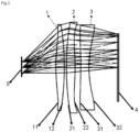
- first lens 2. second lens; 3. third lens; 4. display screen; 5. human eye; 11. first surface; 12. second surface; 21. third surface; 22. fourth surface; 31. fifth surface; 32. sixth surface.
- an optical system is provided.
- the optical system is a direct transmission optical system having short-focus, lightweight and high-resolution, which is suitable for application in electronic devices, for example, head mounted displays (HMD) such as VR devices (such as VR glasses or VR helmets). It has a good application prospect.
- HMD head mounted displays
- VR devices such as VR glasses or VR helmets
- the optical system according to an embodiment of the present disclosure, as shown in FIGS. 1 and 2 , comprises a third lens 3, a second lens 2 and a first lens 1 arranged successivly along the propagation direction of the incident light.
- the optical system according to the embodiment of the present disclosure is designed as a direct transmission optical path structure.
- the design of optical path structure is relatively simple and thus is easy to make.
- optical system may also comprise a display screen 4.
- the display screen 4 can be used to emit light, i.e., to provide an incident light for the optical system.
- a lens combination is designed and used, which comprises, for example, three optical lenses, as shown in FIGS. 1 and 2 .
- the lens combination is arranged at a light exit side of the display screen 4 (specifically, in the propagation direction of the incident light emitted from the display screen 4), and can be used to project the incident light into the human eye 5 for imaging, thereby realizing the imaging function of the optical system.
- the spot size is small (about 50 ⁇ m), and the imaging quality of the entire optical system is good.
- the optical system there are two adjacent Fresnel surfaces, and at least one of the Fresnel surfaces has a curved base.
- the use of the Fresnel surface having a curved base increases the design freedom of optical path structure, and provides a basis for further improving the imaging quality. It is helpful to form an optical structure with high resolution and short-focus.
- At least one of the Fresnel surfaces adopts a curved base, which, compared with the traditional Fresnel surface having a flat base, can improve the imaging quality by about 25% (from 35 ⁇ m to 48 ⁇ m), reduce the total optical length by about 1mm, and reduce the overall weight of the entire optical system by about 8.2%. This makes the optical system have the features of lightweight and miniaturization as well as good imaging quality.
- the embodiment of the present disclosure proposes a solution of short-focus and lightweight optical structure, in which a lens group is formed by multiple lenses (such as three optical lenses), two adjacent Fresnel surfaces are designed in the optical path structure, and at least one of the Fresnel surfaces has a curved base. Since the use of the Fresnel surface having a curved base can make the lens thinner, the design can reduce the total weight of the optical system; it can also reduce the total optical length of the entire optical system and improve the imaging quality.
- the optical system obtained in this way can be applied in, for example, head mounted displays (such as VR devices), and facilitates the miniaturization and lightweight of head mounted displays.
- the solution according to the embodiment of the present disclosure overcomes the problems caused by the conventional combination solution of one-piece lens plus display screen, i.e., the lens is far away from the display screen, which leads to the larger size of the VR device and is not conducive to the miniaturization of the product; moreover, the light efficiency is low.
- it can also overcome the defects caused by using a folded optical path, and has relatively low processing difficulty and production cost; the direct transmission optical structure is also simpler than the folded optical path.
- the one-piece lens (1P) structure only has two surfaces for optimization of surface freedom, its convergence ability is limited, and the aberration or chromatic aberration cannot be corrected.
- the pixel size i.e., spot size
- the pixel size that can be distinguished in the full field of view is about 80 ⁇ m to 100 ⁇ m. More importantly, it cannot realize short-focus.
- the two-piece lens (2P) structure increases the surface freedom of lens surface for optimization and can realize short-focus, but it still has the limitation of resolution. Its pixel size (i.e., spot size) that can be distinguished in the full field of view is about 60 ⁇ m to 80 ⁇ m.
- the optical lens combination structure is adopted, and it can further improve the resolution of the pixel and correct the chromatic aberration to a certain extent.
- What is formed is a direct transmission short-focus optical path structure.
- the imaging spot size of the entire optical system is small (about 50 ⁇ m), the imaging effect is good.
- the first lens 1 and the second lens 2 both have positive focal powers, and the third lens 3 has a negative focal power.
- the first lens 1 and the second lens 2 are positive lenses, for example; the third lens 3 is a negative lens, for example.
- two positive lenses cooperate with one negative lens to form a direct transmission short-focus high-resolution optical path structure.
- the first lens 1 and the second lens 2 cooperating with their Fresnel surfaces, can provide a large focal power.
- the negative lens i.e., the third lens 3
- the participation of the negative lens the low dispersion effect of the optical path structure can be achieved.
- two adjacent surfaces of the first lens 1 and the second lens 2 are Fresnel surfaces, and at least one of the Fresnel surfaces has a curved base.
- At least one of the two adjacent Fresnel surfaces has a curved base.
- one Fresnel surface is a curved base
- the other Fresnel surface is a flat base, and they are arranged adjacent to each other.
- the first lens 1 comprises a first surface 11 and a second surface 12
- the second lens 2 comprises a third surface 21 and a fourth surface 22.
- the first surface 11 and the fourth surface 22 are both aspherical surfaces.
- first surface 11 and the fourth surface 22 are both convex surfaces.
- the first surface 11 of the first lens 1 directly faces the human eye 5, and the first surface 11 is plated with an anti-reflection film and a hardened film; the second surface 12 of the first lens 1 is arranged adjacent to the third surface 21 of the second lens 2, and the second surface 12 is plated with an anti-reflection film.
- the surface shapes of the first surface 11 and the second surface 12 are different.
- the first surface 11 is set as an aspherical surface (a convex surface)
- the second surface 12 is set as a Fresnel surface having a curved base.
- the first lens 1 has a combined surface shape of two surface shapes: aspherical surface + Fresnel surface having a curved base, which can realize short-focus and high resolution.
- the second surface 12 may also be a Fresnel surface having a flat base.
- At least one layer of anti-reflection film is plated on the first surface 11 and the second surface 12 of the first lens 1 respectively. This is because, after the two surfaces of the first lens 1 are respectively plated with an anti-reflection film, the anti-reflection film can be used to reduce reflected light, thereby increasing the transmissivity of light on each surface of the positive lens.
- the first surface 11 of the first lens 1 may be plated with a hardened film in addition to the anti-reflection film.
- the reason is that the first surface 11 of the first lens 1 faces outward and needs to avoid scratches, collisions and other damages.
- the service life of the first lens 1 can be improved by plating the hardened film.
- the hardness, strength, etc. of the first surface 11 can be improved by plating the hardened film on the first surface 11 (i.e., hardening the first surface 11). This is beneficial to improve the service life of the entire optical system.
- the second surface 12 of the first lens 1 may also be plated with a hardened film.
- Those skilled in the art can flexibly adjust according to specific needs, and the present disclosure has no particular limitation herein.
- the first lens 1 has the following parameters.
- the absolute value of the radius R1 of the first surface 11 of the first lens 1 satisfies 45mm ⁇ Abs (R1) ⁇ 65mm;
- the conic constant (i.e., the above K1) of the first lens 1 is, for example, within [-10, 10], and the radius R of the Fresnel surface (i.e., the second surface 12) of the curved base of the first lens 1 is greater than 23mm.
- the second lens 2 and the first lens 1 may have the same combination form of surface shapes.
- the third surface 21 of the second lens 2 is a Fresnel surface (for example, a Fresnel surface having a curved base), and the fourth surface 22 of the second lens 2 is set as an aspherical surface (for example, a convex surface).
- the Fresnel surface of the first lens 1 i.e. the second surface 12
- the Fresnel surface of the second lens 2 i.e. the third surface 21
- the third surface 21 and the fourth surface 22 are also plated with an anti-reflection film.
- the reflection light is reduced through the anti-reflection film, thereby increasing the transmissivity of light on the two surfaces of the second lens 2.
- the second lens 2 may further have the following parameters.
- the absolute value of the radius R0' of the curved base on the third surface 21 satisfies 60mm ⁇ Abs (R0') ⁇ 170mm, and the absolute value of the radius R3 of the third surface 21 satisfies 20mm ⁇ Abs (R3) ⁇ 40mm;
- the surface combination of the second lens 2 is the same as that of the first lens 1.
- the conic constant (i.e., the above K2) of the second lens 2 is, for example, within [-10, 10], and the radius R of the Fresnel surface (i.e., the third surface 21) of the curved base of the second lens 2 is greater than 23mm.
- the first lens 1 and the second lens 2 both have Fresnel surfaces. Considering the processing of lens surface shape, it is necessary to set the surface parameter within a certain range, otherwise the processing accuracy will be low or the cutter may break (this is because the tooth shape processing is difficult, and if the acute angle of the tooth shape is smaller, the processing angle and action will be more difficult). Because of this, it is preferable to set the conic constant K value within the range of [-10, 10], and the R value of the Fresnel surface is greater than 23mm.
- the first lens 1 and the second lens 2 both adopt a combination of aspherical surface + Fresnel surface having a curved base, and by selecting and cooperating with materials having different refractive indexes and Abbe numbers, low dispersion and short-focus of the optical path structure can be achieved.
- the third lens 3 comprises a fifth surface 31 and a sixth surface 32, and at least one of the fifth surface 31 and the sixth surface 32 is an aspherical surface.
- the third lens 3 is a negative lens (having a negative power), which is thin at the center and thick at the edge and has the ability to diverge light. In the entire optical path structure, the third lens 3 can be used to eliminate chromatic aberration.
- the third lens 3 may be a biconcave lens (i.e., both surfaces are concave) or a plano-concave lens (i.e., one surface is concave and the other surface is flat).
- the fifth surface 31 is a flat surface
- the sixth surface 32 is a concave surface.
- the face adjacent to the fourth surface 22 is a flat surface
- the face adjacent to the display screen 4 is a concave surface.
- the fifth surface 31 and the sixth surface 32 are both plated with an anti-reflection film.
- the reflection light can be reduced by the anti-reflection film to increase the transmissivity of light on the two surfaces of the third lens 3.
- the lens group and the surface combination in the lenses in the present disclosure well realize high resolution and low dispersion.
- the third lens 3 may further have the following parameters.
- the absolute value of the radius R5 of the fifth surface 31 of the third lens 3 satisfies Abs (R5) ⁇ 200mm; the absolute value of the radius R6 of the sixth surface 32 of the third lens 3 satisfies 30mm ⁇ Abs (R6) ⁇ 60mm; the absolute value of the conic constant K3 of the fifth surface 31 and the sixth surface 32 of the third lens 4 satisfies Abs (K3) ⁇ 10.
- the optical system comprises: the display screen 4, and the first lens 1, the second lens 2 and the third lens 3.
- the display screen 4 acts as a display light source.
- the first lens 1 and the second lens 2 are optical elements formed by aspherical surface + Fresnel surface having a curved base, and the third lens 3 on the side close to the display screen 4 is set as a negative lens.
- Each surface of each lens is plated with an anti-reflection film, and the first surface 11 of the first lens 1 is plated with a hardened film and an anti-reflection film.
- the light emitted from the display screen 4 passes through the sixth surface 32 of the third lens 3 plated with an anti-reflection film, and enters the interior of the third lens 3.
- the light passing through the third lens 3 is diverged and enters the second lens 2.
- Two surfaces of the second lens 2 are also both plated with an anti-reflection film. In this way, the light is converged after passing through the second lens 2, and then enters the first lens 1.
- the first lens 1 is also a converging positive lens. After passing through the first lens 1, the light enters the human eye 5 for imaging. There is no optical path folding in the entire optical system, and the surface of each lens is plated with an anti-reflection film, so the light transmission efficiency is high.
- a first spacing T1 is provided between the first lens 1 and the second lens 2; a second spacing T2 is provided between the third lens 3 and the second lens 2, and the second spacing T2 is greater than the first spacing T1.
- a first spacing T1 is provided between the first lens 1 and the second lens 2, the first spacing T1 is set to 0.2mm ⁇ T1 ⁇ 1mm; a second spacing T2 is provided between the second lens 2 and the third lens 3, and the second spacing T2 is set to 1mm ⁇ T2 ⁇ 3mm; the first lens, the second lens and the third lens are located on the same optical axis.
- a narrow air gap is provided between the first lens 1 and the second lens 2; at the same time, a narrow air gap is also provided between the second lens 2 and the third lens 3.
- the optical system is also provided with a display screen 4, after the spacings between lenses are reasonably arranged, the value of the spacing between the third lens 3 and the display screen 4 should also be considered.
- a third spacing T3 is provided between the third lens 3 and the display screen 4.
- the first lens 1 and the second lens 2 are made of the same material, and both are made of a COP material; the third lens 3 is made of an OKP material or an EP material.
- COP materials, OKP materials and EP materials are all light transmitting resin materials with light weight. By using these materials to make lenses, the weight of lens groups can be reduced and thus lightweight can be realized.
- each lens For material selection of each lens, based on the consideration of short-focus and chromatic aberration, the combinations of materials having high refractive indexes and high/low Abbe numbers are selected for design optimization.
- the materials of the first lens 1, the second lens 2 and the third lens 3 can reasonably select the materials of the first lens 1, the second lens 2 and the third lens 3 according to actual needs, which are not limited to the above types of materials.
- the thickness h1 at the center of the first lens 1 is 2mm ⁇ h1 ⁇ 4mm; the thickness h2 at the center of the second lens 2 is 3mm ⁇ h2 ⁇ 5mm; the thickness h3 at the center of the third lens 3 is 2mm ⁇ h3 ⁇ 4mm.
- each lens will not be too thick, which is also conducive to reducing the weight of the entire optical path structure.
- the effective focal length f1 of the first lens 1 is 20mm ⁇ f1 ⁇ 40mm; the effective focal length f2 of the second lens 2 is 20mm ⁇ f2 ⁇ 40mm; the effective focal length f3 of the third lens 3 is -75mm ⁇ f3 ⁇ -35mm.
- the effective focal length f1 of the first lens 1 and the effective focal length f2 of the second lens 2 are both greater than the effective focal length f of the optical system.
- the sum of the effective focal length f1 of the first lens 1 and the effective focal length f2 of the second lens 2 is greater than the absolute value of the effective focal length f3 of the optical system.
- the effective focal length f of the optical system satisfies 15mm ⁇ f ⁇ 25mm.
- the present disclosure provides a short-focus optical system. There is no optical path folding in the entire optical system. It is a direct transmission optical system that can achieve high-resolution imaging.
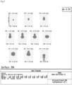
- the first embodiment provides an optical system, and the structure parameters in the optical system are shown in Table 1.
- Table 1 lists the optical surface numbers (Surface) that are numbered sequentially from the human eye 5 (diaphragm) to the display screen 4, the curvature (C) of each optical surface on the optical axis, the distance (T) between each optical surface and the next optical surface on the optical axis from the human eye 5 (diaphragm) to the display screen 4, and even aspheric coefficients ⁇ 2 , ⁇ 3 , ⁇ 4 .
- z is a coordinate along the optical axis
- Y is a radial coordinate having the unit of lens length as unit
- C is the curvature (1/R)
- K is the conic constant
- ⁇ i is the coefficient of each higher-order term
- 2i is the order of aspheric coefficient.
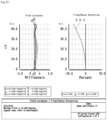
- the maximum spot size is at the position of the maximum field of view (1.0F), and its maximum value is less than 35 ⁇ m.
- the field curvatures of RGB wavelengths in T and S directions are less than 0.5mm, and the maximum distortion is at the position of the maximum field of view and is less than 34.5%.
- the maximum dispersion of RGB is at the position of the maximum field of view, the whole RGB is 450nm to 610nm, and the LCA is 158nm.
- the second embodiment provides an optical system.
- the structural parameters of the optical system are shown in Table 2.
- Table 2 Su rf Type Radi us Thick ness GL ASS Clear Diam Coni c 4th 6th M ax ter m Curva ture Coni c Coeff -4th Coeff -6th OB J STAND ARD Infini ty -1500 3000 0 ST O STAND ARD Infini ty 12 4 0 2 EVEN ASPH 59.42 613 3.20 K26 R 26.914 -10.0 0017 -4.931 E-005 -7.367 E-008 3 XFRES NEL -40 0.931 28.771 83 0 3 -4.23E -02 -7.39 E-01 -1.16 E-05 -3.51 E-07 4 XFRES NEL 169.0 43 3.811 K26 R 31.642 95 0 3 2.83E-02 2.95E -01 2.32E -05 6.10E -
- optical system of the second embodiment of the present disclosure is demonstrated by the following parameters.
- the maximum spot size is at the position of the maximum field of view (1.0F), and its maximum value is less than 30 ⁇ m.
- the field curvatures of RGB wavelengths in T and S directions are less than 0.5mm, and the maximum distortion is at the position of the maximum field of view and is less than 31%.
- the maximum dispersion of RGB is at the position of the maximum field of view, the whole RGB is 450nm to 630nm, and the LCA is 160nm.
- the third embodiment provides an optical system.
- the structural parameters of the optical system are shown in Table 3.
- Table 3 Su rf Type Radiu s Thickn ess GLA SS Clear Diam Coni c 4th 6th M ax ter m Curva ture Conic Coeff-4 th Coeff-6 th O BJ STAN D ARD Infini ty -1500.
- optical system of the third embodiment is demonstrated by the following parameters.
- the maximum spot size is at the position of the maximum field of view (0.9F), and its maximum value is less than 31 ⁇ m.
- the field curvatures of RGB wavelengths in T and S directions are less than 0.5mm, and the maximum distortion is at the position of the maximum field of view and is less than 38%.
- the maximum dispersion of RGB wavelengths is at the position of the maximum field of view, the whole RGB is 450nm to 630nm, and the LCA is 140nm.
- the embodiments of the present disclosure provide a short-focus optical system, which does not involve a folded optical path.
- a head mounted display is provided.
- the head mounted display comprises an optical system as described above.
- the head mounted display is, for example, a VR device.
Landscapes
- Physics & Mathematics (AREA)
- General Physics & Mathematics (AREA)
- Optics & Photonics (AREA)
- Lenses (AREA)
Claims (7)
- Ein optisches System, bestehend aus:eine dritte Linse (3), eine zweite Linse (2) und eine erste Linse (1), die entlang einer Ausbreitungsrichtung eines einfallenden Lichts hintereinander angeordnet sind;wobei eine effektive Brennweite f1 der ersten Linse (1) 20mm ≤ f1 ≤ 40mm beträgt,wobei eine effektive Brennweite f2 der zweiten Linse (2) 20mm ≤ f2 ≤ 40mm beträgt, undwobei eine effektive Brennweite f3 der dritten Linse (3) -75mm ≤ f3 ≤ -35mm beträgt,wobei die erste Linse (1) eine erste Oberfläche (11) und eine zweite Oberfläche (12) umfasst und die zweite Linse (2) eine dritte Oberfläche (21) und eine vierte Oberfläche (22) umfasst; wobei die zweite Oberfläche (12) und die dritte Oberfläche (21) nebeneinander angeordnet sind und beide als Fresnel-Flächen ausgebildet sind und mindestens eine der Fresnel-Flächeneine gekrümmte Basis hat; und die erste Oberfläche (11) und die vierte Oberfläche (22) beide asphärische Flächen sind,wobei der absolute Wert des Radius R1 der ersten Oberfläche (11) der ersten Linse (1) 45 mm ≤ Abs (R1) ≤ 65 mm erfüllt;wobei der Absolutwert des Radius R0 der gekrümmten Basis auf der zweiten Oberfläche (12) der ersten Linse (1) 40 mm ≤ Abs (R0) ≤ 200 mm erfüllt, und der Absolutwert des Radius R2 der zweiten Oberfläche (12) 20 mm ≤ Abs (R2) ≤ 40 mm erfüllt;wobei der Absolutwert der Kegelkonstante K1 der ersten Oberfläche (11) und der zweiten Oberfläche (12) der ersten Linse (1) die Bedingung Abs (K1) ≤ 10 erfüllt,wobei der Absolutwert des Radius R0' der gekrümmten Basis auf der dritten Oberfläche (21) 60 mm ≤ Abs (R0') ≤ 170 mm erfüllt, und der Absolutwert des Radius R3 der dritten Oberfläche (21) 20 mm ≤ Abs (R3) ≤ 40 mm erfüllt;der Absolutwert des Radius R4 der vierten Oberfläche (22) 60 mm ≤ Abs (R4) ≤ 80 mm erfüllt;wobei der Absolutwert der Kegelkonstante K2 der dritten Oberfläche (21) und der vierten Oberfläche 22 der zweiten Linse 2 die Bedingung Abs (K2) ≤ 10 erfüllt.
- Optisches System nach Anspruch 1, wobei die erste Linse (1) und die zweite Linse (2) beide eine positive Brechkraft haben und die dritte Linse (3) eine negative Brechkraft hat.
- Optisches System nach Anspruch 1, wobei ein erster Abstand (T1) zwischen der ersten Linse (1) und der zweiten Linse (2) vorgesehen ist, wobei der erste Abstand (T1) auf 0,2 mm ≤ T1 ≤ 1 mm eingestellt ist;wobei ein zweiter Abstand (T2) zwischen der zweiten Linse (2) und der dritten Linse (3) vorgesehen ist, und der zweite Abstand (T2) auf 1 mm ≤ T2 ≤ 3 mm eingestellt ist; undwobei die erste Linse (1), die zweite Linse (2) und die dritte Linse (3) auf einer gemeinsamen optischen Achse liegen.
- Optisches System nach Anspruch 1, wobei die dritte Linse (3) eine fünfte Oberfläche (31) und eine sechste Oberfläche (32) umfasst und mindestens eine der fünften Oberfläche (31) und der sechsten Oberfläche (32) eine asphärische Fläche ist.
- Optisches System nach Anspruch 1, wobei die erste Linse (1) und die zweite Linse (2) aus demselben Material hergestellt sind und aus einem COP-Material hergestellt sind; und
die dritte Linse (3) aus einem OKP-Material oder einem EP-Material besteht. - Optisches System nach Anspruch 1, wobei die effektive Brennweite f des optischen Systems 15 mm ≤ f ≤ 25 mm beträgt.
- Kopfmontierte Anzeigevorrichtung, umfassend das optische System nach einem der Ansprüche 1 bis 6.
Applications Claiming Priority (2)
| Application Number | Priority Date | Filing Date | Title |
|---|---|---|---|
| CN202111449752.2A CN114236833A (zh) | 2021-11-30 | 2021-11-30 | 一种光学系统以及头戴显示设备 |
| PCT/CN2021/140005 WO2023097812A1 (zh) | 2021-11-30 | 2021-12-21 | 光学系统以及头戴显示设备 |
Publications (3)
| Publication Number | Publication Date |
|---|---|
| EP4212944A1 EP4212944A1 (de) | 2023-07-19 |
| EP4212944A4 EP4212944A4 (de) | 2024-03-20 |
| EP4212944B1 true EP4212944B1 (de) | 2025-06-11 |
Family
ID=80752425
Family Applications (1)
| Application Number | Title | Priority Date | Filing Date |
|---|---|---|---|
| EP21953029.2A Active EP4212944B1 (de) | 2021-11-30 | 2021-12-21 | Optisches system und kopfmontierte anzeigevorrichtung |
Country Status (6)
| Country | Link |
|---|---|
| US (1) | US12535623B2 (de) |
| EP (1) | EP4212944B1 (de) |
| JP (1) | JP7588229B2 (de) |
| KR (1) | KR20230084127A (de) |
| CN (1) | CN114236833A (de) |
| WO (1) | WO2023097812A1 (de) |
Family Cites Families (27)
| Publication number | Priority date | Publication date | Assignee | Title |
|---|---|---|---|---|
| JP3430615B2 (ja) * | 1994-03-04 | 2003-07-28 | 三菱電機株式会社 | 接眼映像表示装置 |
| JP2000002933A (ja) * | 1999-03-15 | 2000-01-07 | Hitachi Ltd | ディスプレイ装置 |
| JPWO2012114970A1 (ja) * | 2011-02-24 | 2014-07-07 | コニカミノルタ株式会社 | 撮像レンズ、撮像装置及び携帯端末 |
| CN102902058B (zh) * | 2012-10-29 | 2014-11-26 | 梧州奥卡光学仪器有限公司 | 连续变倍目镜 |
| CN104536129B (zh) * | 2014-12-17 | 2017-02-08 | 歌尔科技有限公司 | 一种微显示目镜、头戴目镜系统和头戴可视设备 |
| CN104635333B (zh) * | 2015-01-26 | 2017-05-31 | 青岛歌尔声学科技有限公司 | 一种目镜、头戴目镜系统和微显示头戴设备 |
| CN205176383U (zh) * | 2015-09-28 | 2016-04-20 | 深圳纳德光学有限公司 | 大视场角目镜光学系统 |
| CN105137590B (zh) * | 2015-09-28 | 2017-09-12 | 深圳纳德光学有限公司 | 大视场角目镜光学系统 |
| CN106842558A (zh) * | 2015-12-03 | 2017-06-13 | 北京航宇荣康科技股份有限公司 | 虚拟现实用曲面菲涅尔光学塑料单透镜光学系统 |
| WO2017181359A1 (zh) | 2016-04-20 | 2017-10-26 | 深圳纳德光学有限公司 | 用于近眼显示的目镜光学系统及头戴显示装置 |
| JP2017211475A (ja) * | 2016-05-25 | 2017-11-30 | キヤノン株式会社 | 観察光学系及びそれを有する観察装置 |
| CN106019567B (zh) * | 2016-06-30 | 2019-09-27 | 北京小鸟看看科技有限公司 | 一种目镜系统和头戴显示设备 |
| US20180067317A1 (en) * | 2016-09-06 | 2018-03-08 | Allomind, Inc. | Head mounted display with reduced thickness using a single axis optical system |
| CN106324838B (zh) * | 2016-09-30 | 2019-04-16 | 中国科学院长春光学精密机械与物理研究所 | 一种虚拟现实设备及虚拟现实系统 |
| JP7086581B2 (ja) * | 2016-12-21 | 2022-06-20 | キヤノン株式会社 | 観察光学系及びそれを有する観察装置 |
| CN107422481A (zh) * | 2017-08-07 | 2017-12-01 | 杭州太若科技有限公司 | 用于实现增强现实的装置和方法 |
| US11454783B2 (en) * | 2018-04-25 | 2022-09-27 | Samsung Electronics Co., Ltd. | Tiled triplet lenses providing a wide field of view |
| WO2020012817A1 (ja) * | 2018-07-09 | 2020-01-16 | ソニー株式会社 | 接眼レンズおよび表示装置 |
| JP7259427B2 (ja) * | 2018-07-09 | 2023-04-18 | ソニーグループ株式会社 | 接眼レンズおよび表示装置 |
| CN208506366U (zh) * | 2018-07-25 | 2019-02-15 | 中山市美景光学信息有限公司 | 一种光学目镜系统 |
| JP2020020935A (ja) * | 2018-07-31 | 2020-02-06 | ソニー株式会社 | 表示装置 |
| CN110824712A (zh) * | 2019-11-26 | 2020-02-21 | 深圳纳德光学有限公司 | 一种大视场角高像质的目镜光学系统及设备 |
| CN111999896B (zh) * | 2020-09-17 | 2022-04-19 | 中航华东光电有限公司 | 用于虚拟现实头戴显示器的目视光学系统 |
| CN112630974A (zh) * | 2020-12-31 | 2021-04-09 | 深圳纳德光学有限公司 | 一种大视场角的目镜光学系统及头戴显示装置 |
| CN112630973A (zh) * | 2020-12-31 | 2021-04-09 | 深圳纳德光学有限公司 | 一种大视场角的目镜光学系统及头戴显示装置 |
| CN112630977A (zh) * | 2020-12-31 | 2021-04-09 | 深圳纳德光学有限公司 | 一种大视场角的目镜光学系统及头戴显示装置 |
| CN213934402U (zh) * | 2020-12-31 | 2021-08-10 | 深圳纳德光学有限公司 | 一种大视场角的目镜光学系统及头戴显示装置 |
-
2021
- 2021-11-30 CN CN202111449752.2A patent/CN114236833A/zh active Pending
- 2021-12-21 WO PCT/CN2021/140005 patent/WO2023097812A1/zh not_active Ceased
- 2021-12-21 JP JP2023527725A patent/JP7588229B2/ja active Active
- 2021-12-21 KR KR1020237008569A patent/KR20230084127A/ko active Pending
- 2021-12-21 US US18/247,004 patent/US12535623B2/en active Active
- 2021-12-21 EP EP21953029.2A patent/EP4212944B1/de active Active
Also Published As
| Publication number | Publication date |
|---|---|
| KR20230084127A (ko) | 2023-06-12 |
| EP4212944A4 (de) | 2024-03-20 |
| JP7588229B2 (ja) | 2024-11-21 |
| WO2023097812A1 (zh) | 2023-06-08 |
| US20240361501A1 (en) | 2024-10-31 |
| US12535623B2 (en) | 2026-01-27 |
| CN114236833A (zh) | 2022-03-25 |
| EP4212944A1 (de) | 2023-07-19 |
| JP2024501610A (ja) | 2024-01-15 |
Similar Documents
| Publication | Publication Date | Title |
|---|---|---|
| EP4212945B1 (de) | Optisches system und kopfmontierte anzeigevorrichtung | |
| EP4215977B1 (de) | Optisches system und kopfmontierte anzeigevorrichtung | |
| EP4212942B1 (de) | Optisches system und kopfmontierte anzeigevorrichtung | |
| EP3929649B1 (de) | Optisches system und vorrichtung mit gossem sichtfled und hoher bildqualität | |
| EP4212943B1 (de) | Optisches system und kopfmontierte anzeigevorrichtung | |
| EP4212944B1 (de) | Optisches system und kopfmontierte anzeigevorrichtung | |
| CN220650992U (zh) | 虚拟现实模组 | |
| CN216748282U (zh) | 一种光学系统以及头戴显示设备 | |
| CN214669835U (zh) | 一种短焦超小型镜头 | |
| CN101210998B (zh) | 一种光学镜头 | |
| CN222189571U (zh) | 光学影像镜头 | |
| CN116859564A (zh) | 目视系统 | |
| EP3018517A1 (de) | Optische Bildgebungslinse |
Legal Events
| Date | Code | Title | Description |
|---|---|---|---|
| STAA | Information on the status of an ep patent application or granted ep patent |
Free format text: STATUS: UNKNOWN |
|
| STAA | Information on the status of an ep patent application or granted ep patent |
Free format text: STATUS: THE INTERNATIONAL PUBLICATION HAS BEEN MADE |
|
| PUAI | Public reference made under article 153(3) epc to a published international application that has entered the european phase |
Free format text: ORIGINAL CODE: 0009012 |
|
| STAA | Information on the status of an ep patent application or granted ep patent |
Free format text: STATUS: REQUEST FOR EXAMINATION WAS MADE |
|
| 17P | Request for examination filed |
Effective date: 20230217 |
|
| AK | Designated contracting states |
Kind code of ref document: A1 Designated state(s): AL AT BE BG CH CY CZ DE DK EE ES FI FR GB GR HR HU IE IS IT LI LT LU LV MC MK MT NL NO PL PT RO RS SE SI SK SM TR |
|
| STAA | Information on the status of an ep patent application or granted ep patent |
Free format text: STATUS: EXAMINATION IS IN PROGRESS |
|
| A4 | Supplementary search report drawn up and despatched |
Effective date: 20240215 |
|
| RIC1 | Information provided on ipc code assigned before grant |
Ipc: G02B 9/12 20060101ALI20240209BHEP Ipc: G02B 25/00 20060101ALI20240209BHEP Ipc: G02B 13/18 20060101ALI20240209BHEP Ipc: G02B 1/04 20060101ALI20240209BHEP Ipc: G02B 30/26 20200101ALI20240209BHEP Ipc: G02B 27/01 20060101AFI20240209BHEP |
|
| 17Q | First examination report despatched |
Effective date: 20240228 |
|
| GRAP | Despatch of communication of intention to grant a patent |
Free format text: ORIGINAL CODE: EPIDOSNIGR1 |
|
| STAA | Information on the status of an ep patent application or granted ep patent |
Free format text: STATUS: GRANT OF PATENT IS INTENDED |
|
| INTG | Intention to grant announced |
Effective date: 20250114 |
|
| DAV | Request for validation of the european patent (deleted) | ||
| DAX | Request for extension of the european patent (deleted) | ||
| RAP3 | Party data changed (applicant data changed or rights of an application transferred) |
Owner name: GOERTEK OPTICAL TECHNOLOGY CO., LTD. |
|
| GRAS | Grant fee paid |
Free format text: ORIGINAL CODE: EPIDOSNIGR3 |
|
| GRAA | (expected) grant |
Free format text: ORIGINAL CODE: 0009210 |
|
| STAA | Information on the status of an ep patent application or granted ep patent |
Free format text: STATUS: THE PATENT HAS BEEN GRANTED |
|
| AK | Designated contracting states |
Kind code of ref document: B1 Designated state(s): AL AT BE BG CH CY CZ DE DK EE ES FI FR GB GR HR HU IE IS IT LI LT LU LV MC MK MT NL NO PL PT RO RS SE SI SK SM TR |
|
| P01 | Opt-out of the competence of the unified patent court (upc) registered |
Free format text: CASE NUMBER: APP_21198/2025 Effective date: 20250505 |
|
| REG | Reference to a national code |
Ref country code: GB Ref legal event code: FG4D |
|
| REG | Reference to a national code |
Ref country code: CH Ref legal event code: EP |
|
| REG | Reference to a national code |
Ref country code: DE Ref legal event code: R096 Ref document number: 602021032302 Country of ref document: DE |
|
| REG | Reference to a national code |
Ref country code: IE Ref legal event code: FG4D |
|
| PG25 | Lapsed in a contracting state [announced via postgrant information from national office to epo] |
Ref country code: ES Free format text: LAPSE BECAUSE OF FAILURE TO SUBMIT A TRANSLATION OF THE DESCRIPTION OR TO PAY THE FEE WITHIN THE PRESCRIBED TIME-LIMIT Effective date: 20250611 Ref country code: FI Free format text: LAPSE BECAUSE OF FAILURE TO SUBMIT A TRANSLATION OF THE DESCRIPTION OR TO PAY THE FEE WITHIN THE PRESCRIBED TIME-LIMIT Effective date: 20250611 |
|
| REG | Reference to a national code |
Ref country code: LT Ref legal event code: MG9D |
|
| PG25 | Lapsed in a contracting state [announced via postgrant information from national office to epo] |
Ref country code: GR Free format text: LAPSE BECAUSE OF FAILURE TO SUBMIT A TRANSLATION OF THE DESCRIPTION OR TO PAY THE FEE WITHIN THE PRESCRIBED TIME-LIMIT Effective date: 20250912 Ref country code: NO Free format text: LAPSE BECAUSE OF FAILURE TO SUBMIT A TRANSLATION OF THE DESCRIPTION OR TO PAY THE FEE WITHIN THE PRESCRIBED TIME-LIMIT Effective date: 20250911 |
|
| REG | Reference to a national code |
Ref country code: NL Ref legal event code: MP Effective date: 20250611 |
|
| PG25 | Lapsed in a contracting state [announced via postgrant information from national office to epo] |
Ref country code: BG Free format text: LAPSE BECAUSE OF FAILURE TO SUBMIT A TRANSLATION OF THE DESCRIPTION OR TO PAY THE FEE WITHIN THE PRESCRIBED TIME-LIMIT Effective date: 20250611 |
|
| PG25 | Lapsed in a contracting state [announced via postgrant information from national office to epo] |
Ref country code: HR Free format text: LAPSE BECAUSE OF FAILURE TO SUBMIT A TRANSLATION OF THE DESCRIPTION OR TO PAY THE FEE WITHIN THE PRESCRIBED TIME-LIMIT Effective date: 20250611 |
|
| PG25 | Lapsed in a contracting state [announced via postgrant information from national office to epo] |
Ref country code: RS Free format text: LAPSE BECAUSE OF FAILURE TO SUBMIT A TRANSLATION OF THE DESCRIPTION OR TO PAY THE FEE WITHIN THE PRESCRIBED TIME-LIMIT Effective date: 20250911 |
|
| PG25 | Lapsed in a contracting state [announced via postgrant information from national office to epo] |
Ref country code: LV Free format text: LAPSE BECAUSE OF FAILURE TO SUBMIT A TRANSLATION OF THE DESCRIPTION OR TO PAY THE FEE WITHIN THE PRESCRIBED TIME-LIMIT Effective date: 20250611 |
|
| PG25 | Lapsed in a contracting state [announced via postgrant information from national office to epo] |
Ref country code: NL Free format text: LAPSE BECAUSE OF FAILURE TO SUBMIT A TRANSLATION OF THE DESCRIPTION OR TO PAY THE FEE WITHIN THE PRESCRIBED TIME-LIMIT Effective date: 20250611 |
|
| PG25 | Lapsed in a contracting state [announced via postgrant information from national office to epo] |
Ref country code: PT Free format text: LAPSE BECAUSE OF FAILURE TO SUBMIT A TRANSLATION OF THE DESCRIPTION OR TO PAY THE FEE WITHIN THE PRESCRIBED TIME-LIMIT Effective date: 20251013 |
|
| REG | Reference to a national code |
Ref country code: AT Ref legal event code: MK05 Ref document number: 1802714 Country of ref document: AT Kind code of ref document: T Effective date: 20250611 |
|
| PG25 | Lapsed in a contracting state [announced via postgrant information from national office to epo] |
Ref country code: IS Free format text: LAPSE BECAUSE OF FAILURE TO SUBMIT A TRANSLATION OF THE DESCRIPTION OR TO PAY THE FEE WITHIN THE PRESCRIBED TIME-LIMIT Effective date: 20251011 |
|
| PGFP | Annual fee paid to national office [announced via postgrant information from national office to epo] |
Ref country code: GB Payment date: 20251229 Year of fee payment: 5 |
|
| PG25 | Lapsed in a contracting state [announced via postgrant information from national office to epo] |
Ref country code: SM Free format text: LAPSE BECAUSE OF FAILURE TO SUBMIT A TRANSLATION OF THE DESCRIPTION OR TO PAY THE FEE WITHIN THE PRESCRIBED TIME-LIMIT Effective date: 20250611 Ref country code: AT Free format text: LAPSE BECAUSE OF FAILURE TO SUBMIT A TRANSLATION OF THE DESCRIPTION OR TO PAY THE FEE WITHIN THE PRESCRIBED TIME-LIMIT Effective date: 20250611 |
|
| PGFP | Annual fee paid to national office [announced via postgrant information from national office to epo] |
Ref country code: FR Payment date: 20251230 Year of fee payment: 5 |
|
| PG25 | Lapsed in a contracting state [announced via postgrant information from national office to epo] |
Ref country code: CZ Free format text: LAPSE BECAUSE OF FAILURE TO SUBMIT A TRANSLATION OF THE DESCRIPTION OR TO PAY THE FEE WITHIN THE PRESCRIBED TIME-LIMIT Effective date: 20250611 |
|
| PG25 | Lapsed in a contracting state [announced via postgrant information from national office to epo] |
Ref country code: PL Free format text: LAPSE BECAUSE OF FAILURE TO SUBMIT A TRANSLATION OF THE DESCRIPTION OR TO PAY THE FEE WITHIN THE PRESCRIBED TIME-LIMIT Effective date: 20250611 |
|
| PG25 | Lapsed in a contracting state [announced via postgrant information from national office to epo] |
Ref country code: EE Free format text: LAPSE BECAUSE OF FAILURE TO SUBMIT A TRANSLATION OF THE DESCRIPTION OR TO PAY THE FEE WITHIN THE PRESCRIBED TIME-LIMIT Effective date: 20250611 |
|
| PG25 | Lapsed in a contracting state [announced via postgrant information from national office to epo] |
Ref country code: SK Free format text: LAPSE BECAUSE OF FAILURE TO SUBMIT A TRANSLATION OF THE DESCRIPTION OR TO PAY THE FEE WITHIN THE PRESCRIBED TIME-LIMIT Effective date: 20250611 |
|
| PG25 | Lapsed in a contracting state [announced via postgrant information from national office to epo] |
Ref country code: RO Free format text: LAPSE BECAUSE OF FAILURE TO SUBMIT A TRANSLATION OF THE DESCRIPTION OR TO PAY THE FEE WITHIN THE PRESCRIBED TIME-LIMIT Effective date: 20250611 |
|
| PG25 | Lapsed in a contracting state [announced via postgrant information from national office to epo] |
Ref country code: DK Free format text: LAPSE BECAUSE OF FAILURE TO SUBMIT A TRANSLATION OF THE DESCRIPTION OR TO PAY THE FEE WITHIN THE PRESCRIBED TIME-LIMIT Effective date: 20250611 |
|
| PGFP | Annual fee paid to national office [announced via postgrant information from national office to epo] |
Ref country code: DE Payment date: 20251231 Year of fee payment: 5 |
|
| PG25 | Lapsed in a contracting state [announced via postgrant information from national office to epo] |
Ref country code: IT Free format text: LAPSE BECAUSE OF FAILURE TO SUBMIT A TRANSLATION OF THE DESCRIPTION OR TO PAY THE FEE WITHIN THE PRESCRIBED TIME-LIMIT Effective date: 20250611 |
|
| PLBE | No opposition filed within time limit |
Free format text: ORIGINAL CODE: 0009261 |
|
| STAA | Information on the status of an ep patent application or granted ep patent |
Free format text: STATUS: NO OPPOSITION FILED WITHIN TIME LIMIT |
|
| REG | Reference to a national code |
Ref country code: CH Ref legal event code: L10 Free format text: ST27 STATUS EVENT CODE: U-0-0-L10-L00 (AS PROVIDED BY THE NATIONAL OFFICE) Effective date: 20260423 |