EP4212943B1 - Optisches system und kopfmontierte anzeigevorrichtung - Google Patents
Optisches system und kopfmontierte anzeigevorrichtung Download PDFInfo
- Publication number
- EP4212943B1 EP4212943B1 EP21953028.4A EP21953028A EP4212943B1 EP 4212943 B1 EP4212943 B1 EP 4212943B1 EP 21953028 A EP21953028 A EP 21953028A EP 4212943 B1 EP4212943 B1 EP 4212943B1
- Authority
- EP
- European Patent Office
- Prior art keywords
- lens
- optical system
- present disclosure
- spacing
- radius
- Prior art date
- Legal status (The legal status is an assumption and is not a legal conclusion. Google has not performed a legal analysis and makes no representation as to the accuracy of the status listed.)
- Active
Links
Images


Classifications
-
- G—PHYSICS
- G02—OPTICS
- G02B—OPTICAL ELEMENTS, SYSTEMS OR APPARATUS
- G02B13/00—Optical objectives specially designed for the purposes specified below
- G02B13/001—Miniaturised objectives for electronic devices, e.g. portable telephones, webcams, PDAs, small digital cameras
- G02B13/0015—Miniaturised objectives for electronic devices, e.g. portable telephones, webcams, PDAs, small digital cameras characterised by the lens design
- G02B13/002—Miniaturised objectives for electronic devices, e.g. portable telephones, webcams, PDAs, small digital cameras characterised by the lens design having at least one aspherical surface
- G02B13/0035—Miniaturised objectives for electronic devices, e.g. portable telephones, webcams, PDAs, small digital cameras characterised by the lens design having at least one aspherical surface having three lenses
-
- G—PHYSICS
- G02—OPTICS
- G02B—OPTICAL ELEMENTS, SYSTEMS OR APPARATUS
- G02B27/00—Optical systems or apparatus not provided for by any of the groups G02B1/00 - G02B26/00, G02B30/00
- G02B27/01—Head-up displays
- G02B27/0101—Head-up displays characterised by optical features
-
- G—PHYSICS
- G02—OPTICS
- G02B—OPTICAL ELEMENTS, SYSTEMS OR APPARATUS
- G02B27/00—Optical systems or apparatus not provided for by any of the groups G02B1/00 - G02B26/00, G02B30/00
- G02B27/01—Head-up displays
- G02B27/017—Head mounted
- G02B27/0172—Head mounted characterised by optical features
-
- G—PHYSICS
- G02—OPTICS
- G02B—OPTICAL ELEMENTS, SYSTEMS OR APPARATUS
- G02B3/00—Simple or compound lenses
- G02B3/02—Simple or compound lenses with non-spherical faces
- G02B3/08—Simple or compound lenses with non-spherical faces with discontinuous faces, e.g. Fresnel lens
-
- G—PHYSICS
- G02—OPTICS
- G02B—OPTICAL ELEMENTS, SYSTEMS OR APPARATUS
- G02B9/00—Optical objectives characterised both by the number of the components and their arrangements according to their sign, i.e. + or -
- G02B9/12—Optical objectives characterised both by the number of the components and their arrangements according to their sign, i.e. + or - having three components only
-
- G—PHYSICS
- G06—COMPUTING OR CALCULATING; COUNTING
- G06F—ELECTRIC DIGITAL DATA PROCESSING
- G06F1/00—Details not covered by groups G06F3/00 - G06F13/00 and G06F21/00
- G06F1/16—Constructional details or arrangements
- G06F1/1613—Constructional details or arrangements for portable computers
- G06F1/163—Wearable computers, e.g. on a belt
-
- G—PHYSICS
- G02—OPTICS
- G02B—OPTICAL ELEMENTS, SYSTEMS OR APPARATUS
- G02B3/00—Simple or compound lenses
- G02B2003/0093—Simple or compound lenses characterised by the shape
Definitions
- the present disclosure belongs to the technical field of optical imaging, more specifically, it relates to an optical system and a head mounted display.
- augmented reality (AR) technology and virtual reality (VR) technology have been applied in intelligent wearable devices and developed rapidly.
- the core component of both the augmented reality technology and the virtual reality technology is the display optical system.
- the display effect of the display optical system will directly determine the quality of intelligent wearable devices.
- intelligent wearable devices also need to meet the requirements of miniaturization and lightweight, and there are also similar requirements for the display optical system.
- the object of the present disclosure is to provide a new technical solution of an optical system and a head mounted display.
- an optical system comprising:
- a first spacing T1 is provided between the first lens and the second lens
- the first lens and the second lens both have positive focal powers.
- Two adjacent surfaces of the first lens and the second lens are Fresnel surfaces.
- the first lens comprises a first surface and a second surface
- the second lens comprises a third surface and a fourth surface
- the third lens comprises a fifth surface and a sixth surface
- the third lens has a negative focal power.
- the first lens and the second lens are made of a same material, and are made of a COP material; and the third lens is made of an OKP material or an EP material.
- An effective focal length f1 of the first lens is 20mm ⁇ f1 ⁇ 40mm;
- an effective focal length f of the lens group is 15mm ⁇ f ⁇ 25mm.
- a head mounted display comprises an optical system as described above.
- the embodiments of the present disclosure propose a design of short-focus, high-resolution, direct transmission optical path structure.
- the optical system obtained can be applied in, for example, head mounted displays (such as VR devices), and facilitates the miniaturization and lightweight of head mounted displays.
- an optical system is provided.
- the optical system is a short-focus, high-resolution, direct transmission optical system, which is suitable for application in electronic devices, for example, head mounted displays (HMD) such as VR devices (such as VR glasses or VR helmets). It has a good application prospect.
- HMD head mounted displays
- VR devices such as VR glasses or VR helmets
- the optical system according to an embodiment of the present disclosure comprises a lens group, which is composed of a third lens 4, a second lens 3 and a first lens 2 arranged successively along the propagation direction of the incident light.
- the lens group there are two Fresnel surfaces arranged adjacent to each other; the optical system has an imaging spot size less than 50 ⁇ m.
- the optical system according to the embodiment of the present disclosure has a direct transmission optical path structure, and the design of optical path structure is relatively simple.
- the optical system may also comprise a display screen 1.
- the display screen 1 can be used to emit light, i.e., the above incident light.
- a lens group comprising three lenses is designed.
- the lens group is arranged at a light exit side of the display screen 1 (specifically, in the propagation direction of the light emitted from the display screen 1), and can be used to project the incident light into the human eye 5 for imaging.
- the imaging spot size is less than 50 ⁇ m. Because the spot size is relatively small, the imaging quality of the entire optical system is good (in fact, the smaller the spot size, the better the imaging effect of the optical system).
- the spot size is all less than two display pixels. It is helpful for the final realization of magnification display of the PPI1000+ display optical system.
- the solution according to the embodiment of the present disclosure by using three lenses to form a lens group (3P structure), designing two adjacent Fresnel surfaces in the optical path structure, and cooperating with a lens close to the incident light side, the low dispersion and short-focus of the optical path can be realized, and the optical system obtained has high light efficiency and can achieve high-resolution imaging.
- 3P structure designing two adjacent Fresnel surfaces in the optical path structure, and cooperating with a lens close to the incident light side
- the embodiment of the present disclosure proposes a design of short-focus, high-resolution, direct transmission optical path structure.
- the optical system obtained can be applied in, for example, head mounted displays (such as VR devices), and facilitates the miniaturization and lightweight of head mounted displays.
- optical system solution according to the embodiment of the present disclosure is lower in processing difficulty and production cost than the conventional solution of folded optical path.
- the solution according to the embodiment of the present disclosure overcomes the problems caused by the conventional combination solution of one-piece lens plus display screen, i.e., the lens is far away from the display screen, which leads to the larger size of the VR device and is not conducive to the miniaturization of the product; moreover, the light efficiency is low.
- it can also overcome the defects caused by using folded optical path, and has relatively low processing difficulty and production cost; the direct transmission optical structure is also simpler than the folded optical path.
- the optical system of the embodiment of the present disclosure also comprises a display screen 1, for example, which is high PPI (for example, 1.4 inch, pixel size 24 ⁇ m).
- a display screen for example, which is high PPI (for example, 1.4 inch, pixel size 24 ⁇ m).
- PPI for example, 1.4 inch, pixel size 24 ⁇ m.
- the conventional one-piece lens (1P) structure or two-piece lens (2P) structure is not enough to distinguish this type of display screen. The reason is as follows.
- the one-piece lens (1P) structure only has two surfaces for optimization of surface freedom, its convergence ability is limited, and the aberration or chromatic aberration cannot be corrected.
- the pixel size i.e., spot size
- the pixel size that can be distinguished in the whole field of view is about 80 ⁇ m to 100 ⁇ m. More importantly, it cannot realize short-focus.
- the two-piece lens (2P) structure increases the surface freedom of lens surface for optimization and can realize short-focus, but it still has the limitation of resolution. Its pixel size (i.e., spot size) that can be distinguished in the whole field of view is about 60 ⁇ m to 80 ⁇ m, and the imaging effect is poor.
- the three-piece lens (3P) structure is adopted, which can further improve the resolution of the pixel and correct the chromatic aberration to a certain extent.
- the spot size of the optical system is less than 50 ⁇ m.
- the lens group formed by the three-piece lens (3P) structure has a short focus. Considering the air gap and short-focus in the optical structure, two adjacent Fresnel surfaces are also designed.
- the third lens 4 is used to eliminate chromatic aberration.
- a first spacing T1 is provided between the first lens 2 and the second lens 3; a second spacing T2 is provided between the third lens 4 and the second lens 3, and the second spacing T2 is greater than the first spacing T1.
- the first lens 2, the second lens 3 and the third lens 4 are located on the same optical axis.
- a narrow air gap is provided between the first lens 2 and the second lens 3; at the same time, a narrow air gap is also provided between the second lens 3 and the third lens 4.
- the first spacing T1 is set to 0.2mm ⁇ T1 ⁇ 1mm
- the second spacing T2 is set to 1mm ⁇ T2 ⁇ 3mm
- the second spacing T2 is greater than the first spacing T1.
- the value of the spacing between the third lens 4 and the display screen 1 should also be considered.
- a third spacing T3 is provided between the third lens 4 and the display screen 1.
- the third spacing T3 is set to 5mm ⁇ T3 ⁇ 15mm.
- the first lens 2 and the second lens 3 both have positive focal powers.
- the first lens 2 and the second lens 3 are both designed as positive lenses.
- the two adjacent faces of the first lens 2 and the second lens 3 are Fresnel faces.
- the first lens 2 comprises a first surface 21 and a second surface 22, and the second lens 3 comprises a third surface 31 and a fourth surface 32.
- the second surface 22 and the third surface 31 are arranged adjacent to each other, and are both Fresnel surfaces.
- the first surface 21 and the fourth surface 32 are both aspherical surfaces.
- the first surface 21 of the first lens 2 directly faces the human eye 5 and is located externally.
- the first surface 21 is set as an aspherical surface (such as a convex surface), for example.
- the second surface 22 of the first lens 2 is set as a Fresnel surface.
- the first lens 2 (positive lens) has a combined surface shape of two surface shapes: aspherical surface + Fresnel surface.
- the first surface 21 and the second surface 22 of the first lens 2 are respectively plated with an anti-reflection (AR) film.
- AR anti-reflection
- the reflected light can be reduced by the anti-reflection films, thereby increasing the transmissivity of light on the two surfaces of the first lens 2.
- the first surface 21 of the first lens 2 may be plated with a hardened film in addition to the anti-reflection film.
- the service life of the first lens 2 can be improved by plating the hardened film.
- the hardness and strength of the first surface 21 can be improved by plating the hardened film on the first surface 21 (i.e., hardening the first surface 21). This is beneficial to improve the service life of the entire optical system.
- the second surface 22 of the first lens 2 may also be plated with a hardened film.
- Those skilled in the art can flexibly adjust according to specific needs, and the present disclosure has not a particular limitation herein.
- the first lens 2 may further have the following parameters.
- the absolute value of the radius R1 of the first surface 21 of the first lens 2 satisfies 35mm ⁇ R1 ⁇ 65mm; the absolute value of the radius R2 of the second surface 22 of the first lens 2 satisfies 20mm ⁇ R2 ⁇ 40mm; the absolute value of the conic constant K1 of the first surface 21 and the second surface 22 of the first lens 2 satisfies K1 ⁇ 20.
- the surface shape of the first surface 21 is different from that of the second surface 22.
- the first surface 21 facing outward is designed as an aspherical surface (such as a convex surface), while the second surface 22 is designed as a Fresnel surface.
- the first lens 2 formed by combining the Fresnel surface and the aspherical surface is used in the optical path structure, it facilitates realizing short-focus and high resolution.
- the value of the conic constant (i.e., K1) of the first lens 2 is, for example, within [-10, 10], and the radius R of the Fresnel surface of the first lens 2 is greater than 23mm.
- the second lens 3 and the first lens 2 may have the same combination form of surface shapes, and a narrow air gap is maintained between them.
- the third surface 31 of the second lens 3 is a Fresnel surface
- the fourth surface 32 of the second lens 3 is an aspherical surface such as a convex surface.
- the second lens 3 which is a positive lens is located between the first lens 2 and the third lens 4, and is closer to the first lens 2.
- the combination of the first lens 2 and the second lens 3 can form a positive lens group, which can provide a large focal power for the entire optical path structure.
- the third surface 31 and the fourth surface 32 are also plated with an anti-reflection film.
- the reflection light is reduced by the anti-reflection films, thereby increasing the transmissivity of light on the two surfaces of the second lens 3.
- the second lens 3 may further have the following parameters.
- the absolute value of the radius R3 of the third surface 31 of the second lens 3 satisfies 20mm ⁇ R3 ⁇ 40mm; the absolute value of the radius R4 of the fourth surface 32 of the second lens 3 satisfies 30mm ⁇ R4 ⁇ 60mm; the absolute value of the conic constant K2 of the third surface 31 and the fourth surface 32 of the second lens 3 satisfies K2 ⁇ 20.
- the value of the conic constant (i.e., K2) of the second lens 3 is, for example, within [-10, 10], and the radius R of the Fresnel surface of the second lens 3 is greater than 23mm. This is substantially the same as the first lens 2.
- the first lens 2 and the second lens 3 both have Fresnel surfaces.
- the surface parameter it is necessary to set the surface parameter within a certain range, otherwise the processing accuracy will be low or the cutter may break (this is because the tooth shape processing is difficult, and if the acute angle of the tooth shape is smaller, the processing angle and action will be more difficult). Because of this, it is preferable to set the conic constant K value within the range of [-10, 10], and the R value of the Fresnel surface of each lens is greater than 23mm.
- the two positive lenses i.e., the first lens 2 and the second lens 3 both take the combination form of aspherical surface (such as convex surface) + Fresnel surface, and realize low dispersion and short-focus of the optical path structure based on the selection and cooperation of materials having different refractive indexes and Abbe numbers.
- the third lens 4 comprises a fifth surface 41 and a sixth surface 42; the fifth surface 41 and the fourth surface 32 are arranged adjacent to each other. At least one of the fifth surface 41 and the sixth surface 42 is an aspherical surface.
- the third lens 4 has a negative focal power.
- the third lens 4 is a negative lens which is thin at the center and thick at the edge and has the ability to emit light. In the entire optical path structure, the third lens 4 can be used to eliminate chromatic aberration.
- the third lens 4 may be a biconcave lens (i.e., both surfaces are concave) or a plano-concave lens (i.e., one surface is concave and the other surface is flat).
- the fifth surface 41 is a flat surface
- the sixth surface 42 is a concave surface. That is, in the optical path structure, the face adjacent to the fourth surface 32 is a flat surface, and the face adjacent to the display screen 1 is a concave surface.
- the third lens 4 may further have the following parameters.
- the absolute value of the radius R5 of the fifth surface 41 of the third lens 4 satisfies R5 ⁇ 30mm; the absolute value of R6 of radius 42 on the sixth surface of the third lens 4 satisfies 30mm ⁇ R6 ⁇ 60mm; the absolute value of the conic constants K3 of the fifth surface 41 and the sixth surface 42 of the third lens 4 satisfy K3 ⁇ 10.
- the fifth surface 41 and the sixth surface 42 are both plated with an anti-reflection film.
- the reflection light can be reduced by the anti-reflection films to increase the transmissivity of light on the two surfaces of the third lens 4.
- the optical system comprises: a display screen 1 and a lens group formed by the first lens 2, the second lens 3 and the third lens 4.
- the display screen 1 acts as a display light source and can emit light. The light can enter the lens group as the incident light.
- the first lens 2 and the second lens 3 are both positive lenses, and both take the combination form of aspherical surface + Fresnel surface; the third lens 4 is a negative lens.
- Each surface of the three lenses is plated with an anti-reflective film, and the first surface 21 of the first lens 2 is plated with a hardened film and an anti-reflective film.
- the imaging beam (light) emitted by the display screen 1 passes through the sixth surface 42 of the third lens 4 plated with an anti-reflection film, and enters the interior of the third lens 4.
- the light passing through the third lens 4 is diverged and enters the second lens 3.
- Two surfaces of the second lens 3 are also both plated with an anti-reflection film, and the second lens 3 is a positive lens. In this way, the light is converged after passing through the second lens 3, and then enters the first lens 2.
- the first lens 2 is also a converging positive lens. After passing through the first lens 2, the light enters the human eye 5 for imaging. There is no optical path folding in the entire optical system, and the surface of each lens is plated with an anti-reflection film, so the light transmission efficiency is high.
- the first lens 2 and the second lens 3 are made of the same material, and both are made of COP materials; the third lens 4 is made of OKP material or EP material.
- COP materials, OKP materials and EP materials are all light transmitting resin materials with light weight. By using these materials to make lenses, the weight of lens groups can be reduced and thus light weight can be realized.
- each lens For material selection of each lens, based on the consideration of short-focus and chromatic aberration, the combinations of materials having high refractive indexes and high/low Abbe numbers are selected for design optimization.
- the thickness h1 at the center of the first lens 2 is 2mm ⁇ h1 ⁇ 4mm; the thickness h2 at the center of the second lens 3 is 3mm ⁇ h2 ⁇ 5mm; the thickness h3 at the center of the third lens 4 is 2mm ⁇ h3 ⁇ 4mm.
- the effective focal length f1 of the first lens 2 is 20mm ⁇ f1 ⁇ 40mm; the effective focal length f2 of the second lens 3 is 20mm ⁇ f2 ⁇ 40mm; the effective focal length f3 of the third lens 4 is -75mm ⁇ f3 ⁇ -35mm.
- the effective focal length f1 of the first lens 2 and the effective focal length f2 of the second lens 3 are both greater than the effective focal length f of the lens group.
- the sum of the effective focal length f1 of the first lens 2 and the effective focal length f2 of the second lens 3 is greater than the absolute value of the effective focal length f3 of the third lens 4.
- the effective focal length f of the lens group satisfies 15mm ⁇ f ⁇ 25mm.
- the present disclosure provides a short-focus optical system. There is no optical path folding in the entire optical system. It is a direct transmission optical system that can achieve high-resolution imaging.
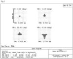
- the first embodiment provides an optical system, and the structure parameters in the optical system are shown in Table 1 below.
- Table 1 lists the optical surface numbers that are numbered sequentially from the human eye 5 (diaphragm) to the display screen 1, the curvature (C) of each optical surface on the optical axis, the distance (T) between each optical surface and the next optical surface on the optical axis from the human eye 5 (diaphragm) to the display screen 1, and even aspheric coefficients ⁇ 2 , ⁇ 3 , ⁇ 4 .
- z is a coordinate along the optical axis
- Y is a radial coordinate in the unit of lens length
- C is the curvature (1/R)
- K is the conic constant
- ⁇ i is the coefficient of each higher-order term
- 2i is the order of aspheric coefficient.
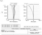
- the maximum spot size is at the position of the maximum field of view (1.0F), and its maximum value is less than 44 ⁇ m. This value is relatively small, which is conducive to improving the imaging quality.
- the field curvatures of RGB wavelengths in T and S directions are less than 0.5mm, and the maximum distortion is at the position of the maximum field of view and is less than 34.6%.
- the maximum dispersion of RGB wavelengths is at the position of the maximum field of view, the whole RGB is 450nm to 610nm, and the LCA is 178nm.
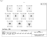
- the second embodiment provides an optical system.
- the structural parameters of the optical system are shown in Table 2 below.
- the optical system is shown in FIG. 6 .
- Table 2 lists the optical surface numbers that are numbered sequentially from the human eye 5 (diaphragm) to the display screen 1, the curvature (C) of each optical surface on the optical axis, the distance (T) between each optical surface and the next optical surface on the optical axis from the human eye 5 (diaphragm) to the display screen 1, and even aspheric coefficients ⁇ 2 , ⁇ 3 , ⁇ 4 .
- optical system of the second embodiment of the present disclosure is demonstrated by the following parameters.
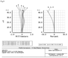
- the maximum spot size is at the position of the maximum field of view (0.9F), and its maximum value is less than 48 ⁇ m. This value is relatively small, which is conducive to improving the imaging quality.
- the field curvatures of RGB wavelengths in T and S directions are less than 0.5mm, and the maximum distortion is at the position of the maximum field of view and is less than 35%.
- the maximum dispersion of RGB is at the position of the maximum field of view, the whole RGB is 450nm to 610nm, and the LCA is 170nm.
- the embodiments of the present disclosure provide a short-focus, high-resolution direct transmission optical system, which does not involve a folded optical path.
- a head mounted display is provided.
- the head mounted display comprises an optical system as described above.
- the head mounted display is, for example, a VR device.
Landscapes
- Physics & Mathematics (AREA)
- General Physics & Mathematics (AREA)
- Optics & Photonics (AREA)
- Engineering & Computer Science (AREA)
- Computer Hardware Design (AREA)
- Theoretical Computer Science (AREA)
- Human Computer Interaction (AREA)
- General Engineering & Computer Science (AREA)
- Lenses (AREA)
Claims (4)
- Ein optisches System, umfassend:eine Linsengruppe umfassend eine dritte Linse (4), eine zweite Linse (3) und eine erste Linse (2), die entlang einer Ausbreitungsrichtung eines einfallenden Lichts hintereinander angeordnet sind;wobei die erste Linse (2) eine erste Fläche (21) und eine zweite Fläche (22) umfasst, die zweite Linse (3) eine dritte Fläche (31) und eine vierte Fläche (32) aufweist, die zweite Fläche (22) und die dritte Fläche (31) nebeneinander angeordnet sind und beide Fresnelflächen sind, die dritte Linse (4) eine fünfte Fläche (41) und eine sechste Fläche (42) aufweist, die fünfte Fläche (41) und die vierte Fläche (32) nebeneinander angeordnet sind,die erste Fläche (21) ist eine konvexe Fläche, die vierte Fläche (32) ist eine konvexe Fläche, mindestens eine der fünften Fläche (41) und der sechsten Fläche (42) ist eine konkave Fläche,das optische System hat eine Bildpunktgröße von weniger als 50 µm, und die Punktgröße beträgt weniger als zwei Anzeigepixel,der absolute Wert des Radius R1 der ersten Fläche (21) erfüllt 35 mm ≤ R1 ≤ 65 mm; der absolute Wert des Radius R2 der zweiten Fläche (22) erfüllt 20 mm ≤ R2 ≤ 40 mm,der absolute Wert des Radius R3 der dritten Fläche (31) erfüllt 20 mm ≤ R3 ≤ 40 mm; der absolute Wert des Radius R4 der vierten Fläche (32) erfüllt 30 mm ≤ R4 ≤ 60 mm,der absolute Wert des Radius R5 der fünften Fläche (41) erfüllt R5 ≥ 30 mm, der absolute Wert des Radius R6 der sechsten Fläche (42) erfüllt 30 mm ≤ R6 ≤ 60 mm,eine effektive Brennweite f1 der ersten Linse (2) beträgt 20 mm ≤ f1 ≤ 40 mm;eine effektive Brennweite f2 der zweiten Linse (3) beträgt 20 mm ≤ f2 ≤ 40 mm;eine effektive Brennweite f3 der dritten Linse (4) ist -75 mm ≤ f3 ≤ -35 mm,ein erster Abstand (T1) zwischen der ersten Linse (2) und der zweiten Linse (3) vorgesehen ist;ein zweiter Abstand (T2) zwischen der dritten Linse (4) und der zweiten Linse (3) vorgesehen ist, und der zweite Abstand (T2) größer als der erste Abstand (T1) ist, und ein dritter Abstand (T3) zwischen der dritten Linse (4) und dem Anzeigeschirm (1) vorgesehen ist; unddie erste Linse (2), die zweite Linse (3) und die dritte Linse (4) auf einer gemeinsamen optischen Achse liegen,der erste Abstand T1 ist auf 0,2 mm ≤ T1 ≤ 1 mm eingestellt, der zweite Abstand T2 ist auf 1 mm ≤ T2 ≤ 3 mm eingestellt, der dritte Abstand T3 ist auf 5 mm ≤ T3 ≤ 15 mm eingestellt,die Dicke h1 in der Mitte der ersten Linse (2) beträgt 2 mm ≤ h1 ≤ 4 mm; die Dicke h2 in der Mitte der zweiten Linse (3) beträgt 3 mm ≤ h2 ≤ 5 mm; die Dicke h3 in der Mitte der dritten Linse (4) beträgt 2 mm ≤ h3 ≤ 4 mm.
- Optisches System nach Anspruch 1, wobei die erste Linse (2) und die zweite Linse (3) aus demselben Material hergestellt sind und aus einem COP-Material hergestellt sind; und
die dritte Linse (4) ist aus einem OKP- oder EP-Material hergestellt. - Optisches System nach Anspruch 1, wobei
eine effektive Brennweite f der Linsengruppe ist 15 mm ≤ f ≤ 25 mm. - Kopfmontierte Anzeige, die das optische System nach einem der Ansprüche 1 bis 3 umfasst.
Applications Claiming Priority (2)
| Application Number | Priority Date | Filing Date | Title |
|---|---|---|---|
| CN202111446819.7A CN114236830B (zh) | 2021-11-30 | 2021-11-30 | 一种光学系统以及头戴显示设备 |
| PCT/CN2021/139986 WO2023097811A1 (zh) | 2021-11-30 | 2021-12-21 | 光学系统以及头戴显示设备 |
Publications (3)
| Publication Number | Publication Date |
|---|---|
| EP4212943A1 EP4212943A1 (de) | 2023-07-19 |
| EP4212943A4 EP4212943A4 (de) | 2024-03-20 |
| EP4212943B1 true EP4212943B1 (de) | 2025-05-14 |
Family
ID=80752321
Family Applications (1)
| Application Number | Title | Priority Date | Filing Date |
|---|---|---|---|
| EP21953028.4A Active EP4212943B1 (de) | 2021-11-30 | 2021-12-21 | Optisches system und kopfmontierte anzeigevorrichtung |
Country Status (6)
| Country | Link |
|---|---|
| US (1) | US20240361575A1 (de) |
| EP (1) | EP4212943B1 (de) |
| JP (1) | JP7607125B2 (de) |
| KR (1) | KR20230084148A (de) |
| CN (1) | CN114236830B (de) |
| WO (1) | WO2023097811A1 (de) |
Families Citing this family (1)
| Publication number | Priority date | Publication date | Assignee | Title |
|---|---|---|---|---|
| CN114839767A (zh) * | 2022-03-31 | 2022-08-02 | 歌尔光学科技有限公司 | 低畸变光学成像调整方法、系统以及头戴显示设备 |
Family Cites Families (20)
| Publication number | Priority date | Publication date | Assignee | Title |
|---|---|---|---|---|
| JP3430615B2 (ja) * | 1994-03-04 | 2003-07-28 | 三菱電機株式会社 | 接眼映像表示装置 |
| JP2000002933A (ja) | 1999-03-15 | 2000-01-07 | Hitachi Ltd | ディスプレイ装置 |
| CN102902058B (zh) * | 2012-10-29 | 2014-11-26 | 梧州奥卡光学仪器有限公司 | 连续变倍目镜 |
| CN104536129B (zh) * | 2014-12-17 | 2017-02-08 | 歌尔科技有限公司 | 一种微显示目镜、头戴目镜系统和头戴可视设备 |
| US11517813B2 (en) * | 2016-02-12 | 2022-12-06 | Hyper Reality Partners, Llc | Hybrid lens for head mount display |
| JP2017211475A (ja) | 2016-05-25 | 2017-11-30 | キヤノン株式会社 | 観察光学系及びそれを有する観察装置 |
| CN106405817A (zh) * | 2016-06-02 | 2017-02-15 | 乐视控股(北京)有限公司 | 一种接目镜片及其生产方法和相应的设备 |
| CN108474935B (zh) * | 2016-07-07 | 2021-02-02 | 株式会社尼康 | 目镜光学系统及头戴式显示器 |
| CN106501928A (zh) * | 2016-11-15 | 2017-03-15 | 上海乐蜗信息科技有限公司 | 一种光学系统 |
| JP7086581B2 (ja) | 2016-12-21 | 2022-06-20 | キヤノン株式会社 | 観察光学系及びそれを有する観察装置 |
| US11454783B2 (en) * | 2018-04-25 | 2022-09-27 | Samsung Electronics Co., Ltd. | Tiled triplet lenses providing a wide field of view |
| JP2020020935A (ja) | 2018-07-31 | 2020-02-06 | ソニー株式会社 | 表示装置 |
| JP7094550B2 (ja) * | 2018-08-24 | 2022-07-04 | 株式会社シグマ | 結像光学系 |
| CN111766700B (zh) * | 2019-04-02 | 2024-12-10 | 东莞双营光电科技有限公司 | 应用于头戴式显示设备的短焦距目镜组件 |
| WO2021102685A1 (zh) * | 2019-11-26 | 2021-06-03 | 深圳纳德光学有限公司 | 一种大视场角高像质的目镜光学系统及设备 |
| CN112433343A (zh) * | 2020-12-03 | 2021-03-02 | 上海悠睿光学有限公司 | 光学成像模组及虚拟现实设备 |
| CN112630977A (zh) * | 2020-12-31 | 2021-04-09 | 深圳纳德光学有限公司 | 一种大视场角的目镜光学系统及头戴显示装置 |
| CN112630974A (zh) * | 2020-12-31 | 2021-04-09 | 深圳纳德光学有限公司 | 一种大视场角的目镜光学系统及头戴显示装置 |
| CN112630973A (zh) * | 2020-12-31 | 2021-04-09 | 深圳纳德光学有限公司 | 一种大视场角的目镜光学系统及头戴显示装置 |
| CN213934402U (zh) * | 2020-12-31 | 2021-08-10 | 深圳纳德光学有限公司 | 一种大视场角的目镜光学系统及头戴显示装置 |
-
2021
- 2021-11-30 CN CN202111446819.7A patent/CN114236830B/zh active Active
- 2021-12-21 WO PCT/CN2021/139986 patent/WO2023097811A1/zh not_active Ceased
- 2021-12-21 KR KR1020237011017A patent/KR20230084148A/ko active Pending
- 2021-12-21 JP JP2023527726A patent/JP7607125B2/ja active Active
- 2021-12-21 US US18/246,993 patent/US20240361575A1/en active Pending
- 2021-12-21 EP EP21953028.4A patent/EP4212943B1/de active Active
Also Published As
| Publication number | Publication date |
|---|---|
| CN114236830B (zh) | 2023-03-28 |
| EP4212943A4 (de) | 2024-03-20 |
| JP7607125B2 (ja) | 2024-12-26 |
| KR20230084148A (ko) | 2023-06-12 |
| WO2023097811A1 (zh) | 2023-06-08 |
| JP2024501102A (ja) | 2024-01-11 |
| EP4212943A1 (de) | 2023-07-19 |
| CN114236830A (zh) | 2022-03-25 |
| US20240361575A1 (en) | 2024-10-31 |
Similar Documents
| Publication | Publication Date | Title |
|---|---|---|
| EP4212945B1 (de) | Optisches system und kopfmontierte anzeigevorrichtung | |
| EP4215977B1 (de) | Optisches system und kopfmontierte anzeigevorrichtung | |
| EP4212942B1 (de) | Optisches system und kopfmontierte anzeigevorrichtung | |
| EP4212943B1 (de) | Optisches system und kopfmontierte anzeigevorrichtung | |
| EP3929649B1 (de) | Optisches system und vorrichtung mit gossem sichtfled und hoher bildqualität | |
| CN110579927B (zh) | 一种小型低f数高清投影镜头 | |
| CN220650992U (zh) | 虚拟现实模组 | |
| EP4212944B1 (de) | Optisches system und kopfmontierte anzeigevorrichtung | |
| CN216748282U (zh) | 一种光学系统以及头戴显示设备 | |
| CN222189571U (zh) | 光学影像镜头 | |
| EP2966487A1 (de) | Optische Bildaufnahmelinse | |
| CN116859564A (zh) | 目视系统 |
Legal Events
| Date | Code | Title | Description |
|---|---|---|---|
| STAA | Information on the status of an ep patent application or granted ep patent |
Free format text: STATUS: UNKNOWN |
|
| STAA | Information on the status of an ep patent application or granted ep patent |
Free format text: STATUS: THE INTERNATIONAL PUBLICATION HAS BEEN MADE |
|
| PUAI | Public reference made under article 153(3) epc to a published international application that has entered the european phase |
Free format text: ORIGINAL CODE: 0009012 |
|
| STAA | Information on the status of an ep patent application or granted ep patent |
Free format text: STATUS: REQUEST FOR EXAMINATION WAS MADE |
|
| 17P | Request for examination filed |
Effective date: 20230217 |
|
| AK | Designated contracting states |
Kind code of ref document: A1 Designated state(s): AL AT BE BG CH CY CZ DE DK EE ES FI FR GB GR HR HU IE IS IT LI LT LU LV MC MK MT NL NO PL PT RO RS SE SI SK SM TR |
|
| STAA | Information on the status of an ep patent application or granted ep patent |
Free format text: STATUS: EXAMINATION IS IN PROGRESS |
|
| A4 | Supplementary search report drawn up and despatched |
Effective date: 20240215 |
|
| RIC1 | Information provided on ipc code assigned before grant |
Ipc: G02B 13/00 20060101ALI20240209BHEP Ipc: G02B 9/12 20060101ALI20240209BHEP Ipc: G02B 3/00 20060101ALI20240209BHEP Ipc: G02B 27/01 20060101AFI20240209BHEP |
|
| 17Q | First examination report despatched |
Effective date: 20240228 |
|
| GRAP | Despatch of communication of intention to grant a patent |
Free format text: ORIGINAL CODE: EPIDOSNIGR1 |
|
| STAA | Information on the status of an ep patent application or granted ep patent |
Free format text: STATUS: GRANT OF PATENT IS INTENDED |
|
| DAV | Request for validation of the european patent (deleted) | ||
| DAX | Request for extension of the european patent (deleted) | ||
| INTG | Intention to grant announced |
Effective date: 20250129 |
|
| GRAS | Grant fee paid |
Free format text: ORIGINAL CODE: EPIDOSNIGR3 |
|
| RAP3 | Party data changed (applicant data changed or rights of an application transferred) |
Owner name: GOERTEK OPTICAL TECHNOLOGY CO., LTD. |
|
| GRAA | (expected) grant |
Free format text: ORIGINAL CODE: 0009210 |
|
| STAA | Information on the status of an ep patent application or granted ep patent |
Free format text: STATUS: THE PATENT HAS BEEN GRANTED |
|
| P01 | Opt-out of the competence of the unified patent court (upc) registered |
Free format text: CASE NUMBER: APP_14050/2025 Effective date: 20250321 |
|
| AK | Designated contracting states |
Kind code of ref document: B1 Designated state(s): AL AT BE BG CH CY CZ DE DK EE ES FI FR GB GR HR HU IE IS IT LI LT LU LV MC MK MT NL NO PL PT RO RS SE SI SK SM TR |
|
| REG | Reference to a national code |
Ref country code: GB Ref legal event code: FG4D |
|
| REG | Reference to a national code |
Ref country code: CH Ref legal event code: EP |
|
| REG | Reference to a national code |
Ref country code: IE Ref legal event code: FG4D |
|
| REG | Reference to a national code |
Ref country code: DE Ref legal event code: R096 Ref document number: 602021030972 Country of ref document: DE |
|
| REG | Reference to a national code |
Ref country code: NL Ref legal event code: MP Effective date: 20250514 |
|
| PG25 | Lapsed in a contracting state [announced via postgrant information from national office to epo] |
Ref country code: PT Free format text: LAPSE BECAUSE OF FAILURE TO SUBMIT A TRANSLATION OF THE DESCRIPTION OR TO PAY THE FEE WITHIN THE PRESCRIBED TIME-LIMIT Effective date: 20250915 Ref country code: FI Free format text: LAPSE BECAUSE OF FAILURE TO SUBMIT A TRANSLATION OF THE DESCRIPTION OR TO PAY THE FEE WITHIN THE PRESCRIBED TIME-LIMIT Effective date: 20250514 Ref country code: ES Free format text: LAPSE BECAUSE OF FAILURE TO SUBMIT A TRANSLATION OF THE DESCRIPTION OR TO PAY THE FEE WITHIN THE PRESCRIBED TIME-LIMIT Effective date: 20250514 |
|
| REG | Reference to a national code |
Ref country code: LT Ref legal event code: MG9D |
|
| PG25 | Lapsed in a contracting state [announced via postgrant information from national office to epo] |
Ref country code: NO Free format text: LAPSE BECAUSE OF FAILURE TO SUBMIT A TRANSLATION OF THE DESCRIPTION OR TO PAY THE FEE WITHIN THE PRESCRIBED TIME-LIMIT Effective date: 20250814 Ref country code: GR Free format text: LAPSE BECAUSE OF FAILURE TO SUBMIT A TRANSLATION OF THE DESCRIPTION OR TO PAY THE FEE WITHIN THE PRESCRIBED TIME-LIMIT Effective date: 20250815 |
|
| PG25 | Lapsed in a contracting state [announced via postgrant information from national office to epo] |
Ref country code: NL Free format text: LAPSE BECAUSE OF FAILURE TO SUBMIT A TRANSLATION OF THE DESCRIPTION OR TO PAY THE FEE WITHIN THE PRESCRIBED TIME-LIMIT Effective date: 20250514 Ref country code: PL Free format text: LAPSE BECAUSE OF FAILURE TO SUBMIT A TRANSLATION OF THE DESCRIPTION OR TO PAY THE FEE WITHIN THE PRESCRIBED TIME-LIMIT Effective date: 20250514 |
|
| REG | Reference to a national code |
Ref country code: AT Ref legal event code: MK05 Ref document number: 1795266 Country of ref document: AT Kind code of ref document: T Effective date: 20250514 |
|
| PG25 | Lapsed in a contracting state [announced via postgrant information from national office to epo] |
Ref country code: BG Free format text: LAPSE BECAUSE OF FAILURE TO SUBMIT A TRANSLATION OF THE DESCRIPTION OR TO PAY THE FEE WITHIN THE PRESCRIBED TIME-LIMIT Effective date: 20250514 |
|
| PG25 | Lapsed in a contracting state [announced via postgrant information from national office to epo] |
Ref country code: HR Free format text: LAPSE BECAUSE OF FAILURE TO SUBMIT A TRANSLATION OF THE DESCRIPTION OR TO PAY THE FEE WITHIN THE PRESCRIBED TIME-LIMIT Effective date: 20250514 |
|
| PG25 | Lapsed in a contracting state [announced via postgrant information from national office to epo] |
Ref country code: AT Free format text: LAPSE BECAUSE OF FAILURE TO SUBMIT A TRANSLATION OF THE DESCRIPTION OR TO PAY THE FEE WITHIN THE PRESCRIBED TIME-LIMIT Effective date: 20250514 |
|
| PG25 | Lapsed in a contracting state [announced via postgrant information from national office to epo] |
Ref country code: RS Free format text: LAPSE BECAUSE OF FAILURE TO SUBMIT A TRANSLATION OF THE DESCRIPTION OR TO PAY THE FEE WITHIN THE PRESCRIBED TIME-LIMIT Effective date: 20250814 |
|
| PG25 | Lapsed in a contracting state [announced via postgrant information from national office to epo] |
Ref country code: IS Free format text: LAPSE BECAUSE OF FAILURE TO SUBMIT A TRANSLATION OF THE DESCRIPTION OR TO PAY THE FEE WITHIN THE PRESCRIBED TIME-LIMIT Effective date: 20250914 |
|
| PG25 | Lapsed in a contracting state [announced via postgrant information from national office to epo] |
Ref country code: LV Free format text: LAPSE BECAUSE OF FAILURE TO SUBMIT A TRANSLATION OF THE DESCRIPTION OR TO PAY THE FEE WITHIN THE PRESCRIBED TIME-LIMIT Effective date: 20250514 |
|
| PGFP | Annual fee paid to national office [announced via postgrant information from national office to epo] |
Ref country code: GB Payment date: 20251229 Year of fee payment: 5 |
|
| PG25 | Lapsed in a contracting state [announced via postgrant information from national office to epo] |
Ref country code: DK Free format text: LAPSE BECAUSE OF FAILURE TO SUBMIT A TRANSLATION OF THE DESCRIPTION OR TO PAY THE FEE WITHIN THE PRESCRIBED TIME-LIMIT Effective date: 20250514 Ref country code: SM Free format text: LAPSE BECAUSE OF FAILURE TO SUBMIT A TRANSLATION OF THE DESCRIPTION OR TO PAY THE FEE WITHIN THE PRESCRIBED TIME-LIMIT Effective date: 20250514 |
|
| PGFP | Annual fee paid to national office [announced via postgrant information from national office to epo] |
Ref country code: FR Payment date: 20251230 Year of fee payment: 5 |
|
| PG25 | Lapsed in a contracting state [announced via postgrant information from national office to epo] |
Ref country code: CZ Free format text: LAPSE BECAUSE OF FAILURE TO SUBMIT A TRANSLATION OF THE DESCRIPTION OR TO PAY THE FEE WITHIN THE PRESCRIBED TIME-LIMIT Effective date: 20250514 |
|
| PG25 | Lapsed in a contracting state [announced via postgrant information from national office to epo] |
Ref country code: EE Free format text: LAPSE BECAUSE OF FAILURE TO SUBMIT A TRANSLATION OF THE DESCRIPTION OR TO PAY THE FEE WITHIN THE PRESCRIBED TIME-LIMIT Effective date: 20250514 |
|
| PG25 | Lapsed in a contracting state [announced via postgrant information from national office to epo] |
Ref country code: SK Free format text: LAPSE BECAUSE OF FAILURE TO SUBMIT A TRANSLATION OF THE DESCRIPTION OR TO PAY THE FEE WITHIN THE PRESCRIBED TIME-LIMIT Effective date: 20250514 |
|
| PG25 | Lapsed in a contracting state [announced via postgrant information from national office to epo] |
Ref country code: IT Free format text: LAPSE BECAUSE OF FAILURE TO SUBMIT A TRANSLATION OF THE DESCRIPTION OR TO PAY THE FEE WITHIN THE PRESCRIBED TIME-LIMIT Effective date: 20250514 |
|
| REG | Reference to a national code |
Ref country code: DE Ref legal event code: R097 Ref document number: 602021030972 Country of ref document: DE |
|
| PG25 | Lapsed in a contracting state [announced via postgrant information from national office to epo] |
Ref country code: RO Free format text: LAPSE BECAUSE OF FAILURE TO SUBMIT A TRANSLATION OF THE DESCRIPTION OR TO PAY THE FEE WITHIN THE PRESCRIBED TIME-LIMIT Effective date: 20250514 |
|
| PLBE | No opposition filed within time limit |
Free format text: ORIGINAL CODE: 0009261 |
|
| STAA | Information on the status of an ep patent application or granted ep patent |
Free format text: STATUS: NO OPPOSITION FILED WITHIN TIME LIMIT |
|
| REG | Reference to a national code |
Ref country code: CH Ref legal event code: L10 Free format text: ST27 STATUS EVENT CODE: U-0-0-L10-L00 (AS PROVIDED BY THE NATIONAL OFFICE) Effective date: 20260325 |
|
| PGFP | Annual fee paid to national office [announced via postgrant information from national office to epo] |
Ref country code: DE Payment date: 20251231 Year of fee payment: 5 |
|
| 26N | No opposition filed |
Effective date: 20260217 |