EP4212727A1 - Rotary compressor - Google Patents
Rotary compressor Download PDFInfo
- Publication number
- EP4212727A1 EP4212727A1 EP22211152.8A EP22211152A EP4212727A1 EP 4212727 A1 EP4212727 A1 EP 4212727A1 EP 22211152 A EP22211152 A EP 22211152A EP 4212727 A1 EP4212727 A1 EP 4212727A1
- Authority
- EP
- European Patent Office
- Prior art keywords
- rotation preventing
- roller
- rotating shaft
- key
- circumferential surface
- Prior art date
- Legal status (The legal status is an assumption and is not a legal conclusion. Google has not performed a legal analysis and makes no representation as to the accuracy of the status listed.)
- Granted
Links
Images







Classifications
-
- F—MECHANICAL ENGINEERING; LIGHTING; HEATING; WEAPONS; BLASTING
- F04—POSITIVE - DISPLACEMENT MACHINES FOR LIQUIDS; PUMPS FOR LIQUIDS OR ELASTIC FLUIDS
- F04C—ROTARY-PISTON, OR OSCILLATING-PISTON, POSITIVE-DISPLACEMENT MACHINES FOR LIQUIDS; ROTARY-PISTON, OR OSCILLATING-PISTON, POSITIVE-DISPLACEMENT PUMPS
- F04C18/00—Rotary-piston pumps specially adapted for elastic fluids
- F04C18/30—Rotary-piston pumps specially adapted for elastic fluids having the characteristics covered by two or more of groups F04C18/02, F04C18/08, F04C18/22, F04C18/24, F04C18/48, or having the characteristics covered by one of these groups together with some other type of movement between co-operating members
- F04C18/34—Rotary-piston pumps specially adapted for elastic fluids having the characteristics covered by two or more of groups F04C18/02, F04C18/08, F04C18/22, F04C18/24, F04C18/48, or having the characteristics covered by one of these groups together with some other type of movement between co-operating members having the movement defined in group F04C18/08 or F04C18/22 and relative reciprocation between the co-operating members
- F04C18/344—Rotary-piston pumps specially adapted for elastic fluids having the characteristics covered by two or more of groups F04C18/02, F04C18/08, F04C18/22, F04C18/24, F04C18/48, or having the characteristics covered by one of these groups together with some other type of movement between co-operating members having the movement defined in group F04C18/08 or F04C18/22 and relative reciprocation between the co-operating members with vanes reciprocating with respect to the inner member
-
- F—MECHANICAL ENGINEERING; LIGHTING; HEATING; WEAPONS; BLASTING
- F04—POSITIVE - DISPLACEMENT MACHINES FOR LIQUIDS; PUMPS FOR LIQUIDS OR ELASTIC FLUIDS
- F04C—ROTARY-PISTON, OR OSCILLATING-PISTON, POSITIVE-DISPLACEMENT MACHINES FOR LIQUIDS; ROTARY-PISTON, OR OSCILLATING-PISTON, POSITIVE-DISPLACEMENT PUMPS
- F04C23/00—Combinations of two or more pumps, each being of rotary-piston or oscillating-piston type, specially adapted for elastic fluids; Pumping installations specially adapted for elastic fluids; Multi-stage pumps specially adapted for elastic fluids
- F04C23/008—Hermetic pumps
-
- F—MECHANICAL ENGINEERING; LIGHTING; HEATING; WEAPONS; BLASTING
- F04—POSITIVE - DISPLACEMENT MACHINES FOR LIQUIDS; PUMPS FOR LIQUIDS OR ELASTIC FLUIDS
- F04C—ROTARY-PISTON, OR OSCILLATING-PISTON, POSITIVE-DISPLACEMENT MACHINES FOR LIQUIDS; ROTARY-PISTON, OR OSCILLATING-PISTON, POSITIVE-DISPLACEMENT PUMPS
- F04C29/00—Component parts, details or accessories of pumps or pumping installations, not provided for in groups F04C18/00 - F04C28/00
- F04C29/0042—Driving elements, brakes, couplings, transmissions specially adapted for pumps
- F04C29/005—Means for transmitting movement from the prime mover to driven parts of the pump, e.g. clutches, couplings, transmissions
- F04C29/0071—Couplings between rotors and input or output shafts acting by interengaging or mating parts, i.e. positive coupling of rotor and shaft
-
- F—MECHANICAL ENGINEERING; LIGHTING; HEATING; WEAPONS; BLASTING
- F04—POSITIVE - DISPLACEMENT MACHINES FOR LIQUIDS; PUMPS FOR LIQUIDS OR ELASTIC FLUIDS
- F04C—ROTARY-PISTON, OR OSCILLATING-PISTON, POSITIVE-DISPLACEMENT MACHINES FOR LIQUIDS; ROTARY-PISTON, OR OSCILLATING-PISTON, POSITIVE-DISPLACEMENT PUMPS
- F04C29/00—Component parts, details or accessories of pumps or pumping installations, not provided for in groups F04C18/00 - F04C28/00
- F04C29/0042—Driving elements, brakes, couplings, transmissions specially adapted for pumps
- F04C29/0078—Fixing rotors on shafts, e.g. by clamping together hub and shaft
-
- F—MECHANICAL ENGINEERING; LIGHTING; HEATING; WEAPONS; BLASTING
- F04—POSITIVE - DISPLACEMENT MACHINES FOR LIQUIDS; PUMPS FOR LIQUIDS OR ELASTIC FLUIDS
- F04C—ROTARY-PISTON, OR OSCILLATING-PISTON, POSITIVE-DISPLACEMENT MACHINES FOR LIQUIDS; ROTARY-PISTON, OR OSCILLATING-PISTON, POSITIVE-DISPLACEMENT PUMPS
- F04C2230/00—Manufacture
- F04C2230/60—Assembly methods
- F04C2230/602—Gap; Clearance
-
- F—MECHANICAL ENGINEERING; LIGHTING; HEATING; WEAPONS; BLASTING
- F05—INDEXING SCHEMES RELATING TO ENGINES OR PUMPS IN VARIOUS SUBCLASSES OF CLASSES F01-F04
- F05C—INDEXING SCHEME RELATING TO MATERIALS, MATERIAL PROPERTIES OR MATERIAL CHARACTERISTICS FOR MACHINES, ENGINES OR PUMPS OTHER THAN NON-POSITIVE-DISPLACEMENT MACHINES OR ENGINES
- F05C2251/00—Material properties
- F05C2251/10—Hardness
Definitions
- This disclosure relates to a rotary compressor in which a rotating shaft is assembled with a roller.
- a rotary compressor is classified into a rotary compressor type in which a vane is slidably inserted into a cylinder to be in contact with a roller, and a rotary compressor type in which a vane is slidably inserted into a roller to be in contact with a cylinder.
- the former is called a rotary compressor with an eccentric roller (hereinafter referred to as a "rotary compressor")
- the latter is called a concentric vane rotary compressor (hereinafter referred to as a "vane rotary compressor”).
- a vane inserted in a cylinder is pulled out toward a roller by elastic force or back pressure to come into contact with an outer circumferential surface of the roller.
- a vane rotary compressor a vane inserted in a roller rotates together with the roller, and is pulled out by centrifugal force and back pressure to come into contact with an inner circumferential surface of a cylinder.
- a rotary compressor independently forms as many compression chambers as the number of vanes per revolution of a roller, and the compression chambers simultaneously perform suction, compression, and discharge strokes.
- a vane rotary compressor continuously forms as many compression chambers as the number of vanes per revolution of a roller, and the compression chambers sequentially perform suction, compression, and discharge strokes. Therefore, the vane rotary compressor provides a higher compression ratio than the rotary compressor. Therefore, the vane rotary compressor is more suitable for high pressure refrigerants such as R32, R410a, and CO2, which have low ozone depletion potential (ODP) and global warming index (GWP).
- ODP ozone depletion potential
- GWP global warming index
- the vane rotary compressor is generally configured such that a center of the roller matches a center of the rotating shaft.
- the vane rotary compressor may be referred to as a concentric vane-type rotary compressor.
- the concentric vane-type rotary compressor is defined as a vane rotary compressor in the description.
- the vane rotary compressor is disclosed in patent document 1 (Japanese Patent Publication No.: JP 2013-072429A ) and patent document 2 (Japanese Patent Publication No.: JP 2013-050038A ).
- the vane rotary compressor in the patent document 1 discloses an example in which a roller is manufactured integrally with a rotating shaft.
- the patent document 2 discloses an example in which a roller and a rotating shaft are separately manufactured, and then, post-assembled with each other.
- an outer circumferential surface of the rotating shaft and an inner circumferential surface of the roller are provided to have a circular shape to be press-fit, or machined to have a serration or gear shape to be pressed or press-fit.
- the roller and the rotating shaft may be coupled to each other using a fixing pin penetrating therethrough.
- the rotating shaft and the roller are provided as a single body.
- the roller axially moves with the rotating shaft coupled to the rotor.
- one axial side surface of the roller i.e., an upper bearing surface
- friction loss or abrasion occurs.
- a gap between the roller and a sub bearing is enlarged in correspondence with raising of the roller, leakage between compression chambers occurs, thereby deteriorating compression efficiency.
- the rotating shaft and the roller are manufactured as a single body as described above, the rotating shaft and the roller are manufactured using a same material.
- the rotating shaft and the roller are separately machined and post-assembled as a single body, the rotating shaft and the roller are also manufactured using a same material or materials having similar rigidity and hardness in consideration of coupling reliability.
- motor efficiency may not be increased.
- the rotating shaft and the roller are post-assembled as a single body, since a change in a post-assembly process may occur, the rotating shaft and the roller are assembled, and then, post-machined.
- primary processing of separately machining the rotating shaft and the roller is performed, then, the rotating shaft and the roller on which the primary machining is performed are post-assembled, and then, secondary machining of grinding a vane slot and a cross section and an outer circumferential surface with respect to the roller is performed.
- secondary machining of grinding a vane slot and a cross section and an outer circumferential surface with respect to the roller is performed.
- a rotary compressor may include a casing, a driving motor, a rotating shaft, a main bearing and a sub bearing, a cylinder, a roller, a vane, and a rotation preventing unit.
- the driving motor may be included inside the casing.
- the rotating shaft may be coupled to a rotor in the driving motor and transmit rotational force.
- the main bearing and the sub bearing may support the rotating shaft.
- the cylinder may be provided between the main bearing and the sub bearing to provide a compression space.
- the roller may be provided with a shaft hole through which the rotating shaft penetrates and is inserted in an axial direction.
- the vane may divide the compression space into a plurality of compression chambers.
- the rotation preventing unit may be provided between an outer circumferential surface of the rotating shaft and an inner circumferential surface of an shaft hole in the roller, the inner circumferential surface facing the outer circumferential surface of the rotating shaft, to constrain rotation of the roller with respect to the rotating shaft.
- the rotation preventing unit may allow axial movement of the roller with respect to the rotating shaft.
- the rotation preventing unit may include a rotation preventing groove and a rotation preventing key.
- the rotation preventing groove may be provided in an inner circumferential surface of the shaft hole.
- the rotation preventing key may be provided on the outer circumferential surface of the rotating shaft and slidably inserted into the rotation preventing groove in an axial direction.
- the rotation preventing key may be post-assembled on the rotating shaft.
- the rotation preventing key constituting the rotation preventing unit may be easily provided on the rotating shaft.
- a key accommodating groove may be provided in the outer circumferential surface of the rotating shaft.
- the rotation preventing key may be inserted and coupled into the key accommodating groove.
- the rotation preventing key may be easily coupled to the rotating shaft, and coupling stability may be also enhanced.
- the rotation preventing unit may include a rotation preventing groove and a rotation preventing key.
- the rotation preventing groove may be provided in an inner circumferential surface of the shaft hole.
- the rotation preventing key may be provided on the outer circumferential surface of the rotating shaft and slidably inserted into the rotation preventing groove in an axial direction.
- the rotation preventing key may extend integrally from the rotating shaft. Thus, assembly of the rotation preventing unit including the rotation preventing key may be simplified.
- the rotation preventing unit may include a rotation preventing groove and a rotation preventing key.
- the rotation preventing groove may be provided in an inner circumferential surface of the shaft hole.
- the shaft hole may be also called axial hole and extends in radial direction through the roller.
- the rotation preventing key may be provided on the outer circumferential surface of the rotating shaft and slidably inserted into the rotation preventing groove in an axial direction.
- An axial length of the rotation preventing key may extend longer than a circumferential width of the rotation preventing key.
- a circumferential area of the rotation preventing key may be greatly reduced, and rotational force may be stably transmitted to the roller.
- the axial length of the key accommodating key may be provided to be equal to or less than an axial length of the rotation preventing groove.
- the rotation preventing key may be suppressed from being hooked on a main bearing or a sub bearing.
- the outer circumferential surface of the rotating shaft may be provided with a roller support surface configured to limit the axial movement of the roller and have a height difference relative to the outer circumferential surface of the rotating shaft.
- the rotating shaft may be axially supported by the roller to enhance assembly stability and, simultaneously, limit axial movement of the roller to suppress friction loss and abrasion between the roller and a bearing.
- the roller support surface may be arranged adjacent to the driving motor with reference to an axial center of the roller.
- excessive ascending of the roller toward a main bearing located at an upper side may be suppressed to reduce friction loss and abrasion between the roller and the main bearing.
- the roller support surface may be provided to have an annular shape.
- the rotating shaft and the roller are uniformly supported in a circumferential direction to stably support the rotating shaft or the roller in an axial direction.
- the rotation preventing unit may include a rotation preventing groove and a rotation preventing key.
- the rotation preventing groove may be provided in an inner circumferential surface of the shaft hole.
- the rotation preventing key may be arranged on the outer circumferential surface of the rotating shaft and slidably inserted into the rotation preventing groove in an axial direction.
- One axial end of the rotation preventing groove may be open and another axial end thereof may be closed to provide a hooking surface to limit axial movement of the rotation preventing key.
- the rotating shaft may be axially supported by the roller to enhance assembly stability and, simultaneously, limit axial movement of the roller to suppress friction loss and abrasion between the roller and a bearing.
- the hooking surface may be provided at an end portion far apart from the driving motor with reference to the axial center of the roller.
- the roller may include a material having lower rigidity or hardness compared to the rotating shaft.
- a weight of the roller may be reduced, thereby reducing load on the driving motor.
- the rotation preventing unit may include a rotation preventing groove and a rotation preventing key.
- the rotation preventing groove may be provided in an inner circumferential surface of the shaft hole.
- the rotation preventing key may be provided on the outer circumferential surface of the rotating shaft and slidably inserted into the rotation preventing groove in an axial direction.
- a first reinforcing member is provided between an inner circumferential surface of the rotation preventing groove and an outer circumferential surface of the rotation preventing key.
- the first reinforcing member may include a material having higher rigidity or hardness compared to the roller.
- the roller may include a material lighter than that of the rotating shaft, and abrasion resistance may be also increased to ensure reliability of the rotation preventing unit.
- a vane slot may be provided in an outer circumferential surface of the roller, the vane being inserted into the vane slot.
- a second reinforcing member is inserted into the vane slot.
- the second reinforcing member may include a material having higher rigidity or hardness compared to the roller.
- the roller may include a light material, and abrasion resistance between the vane and the vane slot may be also increased to ensure compressor performance.
- a back pressure pocket communicating with the inside of the casing may be on at least one from among a sliding surface of the main bearing and a sliding surface of the sub bearing, the sliding surface of the main bearing facing one axial side surface of the roller and a sliding surface of the sub bearing facing another axial side surface of the roller. Therefore, excessive axial movement of the roller due to pressure of oil in the back pressure pocket may be suppressed, and thus, friction loss and abrasion between the roller and a bearing facing the roller may be suppressed.
- the back pressure pocket may at least partially overlap the rotation preventing unit in an axial direction.
- the oil in the back pressure pocket may flow into the rotation preventing unit to smoothly lubricate between the rotation preventing groove and the rotation preventing key both included in the rotation preventing unit.
- the inner circumferential surface of the cylinder may be formed in an elliptical shape.
- the inner circumferential surface of the cylinder may be formed in a circular shape.
- the present disclosure provides a roller assembled with a rotating shaft and coupled thereto to be movable in an axial direction within a certain range. This may apply to not only a vane rotary compressor in which a vane is slidably inserted into a roller, but also a general rotary compressor in which a vane is slidably inserted into a cylinder.
- a vane rotary compressor is described as a representative example.
- FIG. 1 is a cross-sectional view illustrating one implementation of the vane rotary compressor according to the present disclosure
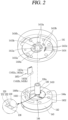
- FIG. 2 is an exploded perspective view illustrating a compression unit of FIG. 1
- FIG. 3 is an assembled planar view of the compression unit in FIG. 2 .
- a vane rotary compressor includes a casing 110, a driving (or drive) motor 120, a rotating shaft 130, and a compression unit 140.
- the driving motor 120 is installed in an upper (a first) inner space 110a of the casing 110
- the compression unit 140 is installed in a lower (a second) inner space 110a of the casing 110.
- the driving motor 120 and the compression unit 140 are connected through a rotating shaft 130.
- the casing 110 that defines an outer appearance of the compressor may be classified as a vertical type and a horizontal type according to a compressor installation method.
- the driving motor 120 and the compression unit 140 are disposed at upper and lower sides in an axial direction, respectively.
- the driving motor 120 and the compression unit 140 are disposed at left and right sides, respectively.
- the casing according to this implementation may be illustrated as the vertical type.
- the driving motor 120 and the compression unit 140 may also disposed in a first and second inner space of the casing respectively.
- the casing 110 includes an intermediate shell 111 having a cylindrical shape, a lower (second) shell 112 covering a lower (second) end of the intermediate shell 111, and an upper (first) shell 113 covering an upper (second) end of the intermediate shell 111.
- the lower and upper shell may be also designated second and first shell, respectively.
- the driving motor 120 and the compression unit 140 may be inserted into the intermediate shell 111 to be fixed thereto.
- a suction pipe 115 may penetrate through the intermediate shell 111 to be directly connected to the compression unit 140.
- the lower shell 112 may be coupled to the lower end of the intermediate shell 111 in a sealing manner.
- An oil storage space 110b in which oil to be supplied to the compression unit 140 is stored may be formed mainly in the lower shell 112 below the compression unit 140.
- the upper shell 113 may be coupled to the upper end of the intermediate shell 111 in a sealing manner.
- An oil separation space 110c may be formed above the driving motor 120 to separate oil from refrigerant discharged from the compression unit 140.
- the driving motor 120 that constitutes a motor unit supplies power to cause the compression unit 140 to be driven.
- the driving motor 120 includes a stator 121 and a rotor 122.
- the stator 121 may be fixedly inserted into the casing 110.
- the stator 121 may be fixed to an inner circumferential surface of the casing 110 in a shrink-fitting manner or the like.
- the stator 121 may be press-fitted into an inner circumferential surface of the intermediate shell 111.
- the rotor 122 may be rotatably inserted into the stator 121, and the rotating shaft 130 may be press-fitted into a center of the rotor 122. Accordingly, the rotating shaft 130 rotates concentrically together with the rotor 122.
- An oil flow path 130a having a hollow hole shape is provided in a central portion of the rotating shaft 130.
- Oil passage holes 130b and 130c are provided through a middle portion of the oil flow path 130a toward an outer circumferential surface of the rotating shaft 130.
- the oil passage holes 130b and 130c include a first oil passage hole 130b belonging to a range of a main bush portion 1412 to be described later and a second oil passage hole 130c belonging to a range of a sub bush portion 1422.
- Each of the first oil passage hole 130b and the second oil passage hole 130c may be provided by one or in plurality. In this implementation, the first and second oil passage holes 130b, 130c are respectively provided in plurality.
- An oil pickup 130d may be installed in a middle portion or a lower end of the oil flow path 130a.
- a gear pump, a viscous pump, a centrifugal pump, or the like may be used for the oil pickup 130d.
- the centrifugal pump is employed is illustrated. Accordingly, when the rotating shaft 130 rotates, oil filled in the oil storage space 110b is pumped by the oil pickup 130d and is sucked along the oil flow path 130a to be supplied into a sub bearing surface (no reference numeral) of the sub bush portion 1422 through the second oil passage hole 130c and into a main bearing surface (no reference numeral) of the main bush portion 1412 through the first oil passage hole 130b.
- the rotating shaft 130 may include a roller 144 to be described later.
- the roller 144 may extend integrally from the rotating shaft 130.
- the rotating shaft 130 and the roller 144 may be separately manufactured, and then, post-assembled with each other.
- the rotating shaft 130 is inserted into the roller 144, and then, post-assembled.
- a shaft hole 1441 may be penetrated through a center of the roller 144 in an axial direction and the rotating shaft 130 may be inserted and coupled into the shaft hole 1441.
- a rotation preventing key 152 may be provided on an outer circumferential surface of the rotating shaft 130, and a rotation preventing groove 151 may be provided in an inner circumferential surface of the roller 144, that is, an inner circumferential surface of the shaft hole 1441.
- the rotation preventing key 152 may protrude in a radial direction, and the rotation preventing groove 151 may be recessed in the radial direction so that the rotation preventing key 152 is inserted therein. Accordingly, the rotating shaft 130 and the roller 144 may be mutually constrained in a circumferential direction.
- the rotation preventing key 152 and rotation preventing groove 151 may be provided between vane slots 1446a, 1446b, and 1446c to be described later, i.e., between two vane slots neighboring in a circumferential direction.
- the rotation preventing unit 150 including the rotation preventing key 152 and the rotation preventing groove 151 may be located in a middle position between the two vane slots. Accordingly, a circumferential side surface of the rotation preventing groove 151 may be prevented from being damaged by a circumferential force delivered through the rotation preventing groove 151.
- the rotation preventing key 152 and the rotation preventing groove 151 may be provided in positions that do not overlap the vane slots 1446a, 1446b, and 1446c in a circumferential direction.
- a virtual circle CL1 connecting an outer side surface of the rotation preventing groove 151 may be provided in a further inner position compared to the vane slots (back pressure chambers) 1446a, 1446b, and 1446c in a radial direction. Accordingly, by reducing a length by which the rotation prevention key 152 radially protrudes, a coupling reliability with respect to the rotation preventing key 152 may be enhanced.
- Only one rotation preventing key 152 and one rotation preventing groove 151 may be provided as illustrated in the drawings, and in some cases, a plurality of rotation preventing keys 152 and a plurality of rotation preventing grooves 151 may be provided at equal intervals along the circumferential direction. A coupling relationship between the rotating shaft 130 and the roller 144 will be described later together with the roller 144.
- the compression unit 140 includes a main bearing 141, a sub bearing 142, a cylinder 143, a roller 144, and a plurality of vanes 1451, 1452, and 1453.
- the main bearing 141 and the sub bearing 142 are respectively provided at upper and lower parts of the cylinder 143 to define a compression space V together with the cylinder 143, the roller 144 is rotatably installed in the compression space V, and the vanes 1451, 1452, and 1453 are slidably inserted into the roller 144 to divide the compression space V into a plurality of compression chambers.
- the main bearing 141 may be fixedly installed in the intermediate shell 111 of the casing 110.
- the main bearing 141 may be inserted into the intermediate shell 111 and welded thereto.
- the main bearing 141 may be coupled to an upper end of the cylinder 143 in a close contact manner. Accordingly, the main bearing 141 defines an upper surface of the compression space V, and supports an upper surface of the roller 144 in the axial direction and at the same time supports an upper portion of the rotating shaft 130 in the radial direction.
- the main bearing 141 may include a main plate portion 1411 and a main bush portion 1412.
- the main plate portion 1411 covers an upper part of the cylinder 143 to be coupled thereto, and the main bush portion 1412 axially extends from a center of the main plate portion 1411 toward the driving motor 120 so as to support the upper portion of the rotating shaft 130.
- the main plate portion 1411 may have a disk shape, and an outer circumferential surface of the main plate portion 1411 may be fixed to the inner circumferential surface of the intermediate shell 111 in a close contact manner.
- One or more discharge ports 1413a, 1413b, and 1413c may be formed in the main plate portion 1411, and a plurality of discharge valves 1461, 1462, and 1463 configured to open and close the respective discharge ports 1413a, 1413b, and 1413c may be installed on an upper surface of the main plate portion 1411, and a discharge muffler 147 having a discharge space (no reference numeral) may be provided at an upper part of the main plate portion 1411 to accommodate the discharge ports 1413a, 1413b, and 1413c, and the discharge valves 1461, 1462, and 1463.
- a first main back pressure pocket 1415a and a second main back pressure pocket 1415b may be formed in a lower surface, namely, a main sliding surface 1411a of the main plate portion 1411 facing the upper surface of the roller 144, of both axial side surfaces of the main plate portion 1411.
- the first main back pressure pocket 1415a and the second main back pressure pocket 1415b each having an arcuate shape may be disposed at a predetermined interval in a circumferential direction.
- Each of the first main back pressure pocket 1415a and the second main back pressure pocket 1415b may have an inner circumferential surface with a circular shape, but may have an outer circumferential surface with an oval or elliptical shape in consideration of vane slots to be described later.
- the first main back pressure pocket 1415a and the second main back pressure pocket 1415b may be formed within an outer diameter range of the roller 144. Accordingly, the first main back pressure pocket 1415a and the second main back pressure pocket 1415b may be separated from the compression space V. However, the first main back pressure pocket 1415a and the second main back pressure pocket 1415b may slightly communicate with each other through a gap between a lower surface, a main sliding surface 1411a of the main plate portion 1411 and the upper surface of the roller 144 facing each other unless a separate sealing member is provided therebetween.
- the first main back pressure pocket 1415a forms pressure lower than pressure formed in the second main back pressure pocket 1415b, for example, forms intermediate pressure between suction pressure and discharge pressure.
- Oil refrigerant oil
- the first main back pressure pocket 1415a may be formed in the range of a compression chamber forming intermediate pressure in the compression space V. This may allow the first main back pressure pocket 1415a to maintain the intermediate pressure.
- the second main back pressure pocket 1415b may form pressure higher than that in the first main back pressure pocket 1415a, for example, discharge pressure or intermediate pressure between suction pressure close to the discharge pressure and the discharge pressure. Oil flowing into the main bearing hole 1412a of the main bearing 1412 through the first oil passage hole 130b may be introduced into the second main back pressure pocket 1415b.
- the second main back pressure pocket 1415b may be formed in the range of a compression chamber forming a discharge pressure in the compression space V. This may allow the second main back pressure pocket 1415b to maintain the discharge pressure.
- a first main bearing protrusion 1416a and a second main bearing protrusion 1416b may be formed on inner circumferential sides of the first main back pressure pocket 1415a and the second main back pressure pocket 1415b, respectively, in a manner of extending from the main bearing surface (no reference numeral) of the main bush potion 1412. Accordingly, the first main back pressure pocket 1415a and the second main back pressure pocket 1415b can be sealed from outside and simultaneously the rotating shaft 130 can be stably supported.
- the first main bearing protrusion 1416a and the second main bearing protrusion 1416b may have the same height or different heights.
- an oil communication groove (not illustrated) or an oil communication hole (not illustrated) may be formed on an end surface of the second main bearing protrusion 1416b such that inner and outer circumferential surfaces of the second main bearing protrusion 1416b can communicate with each other. Accordingly, high-pressure oil (refrigerant oil) flowing into the main bearing surface (no reference numeral) can be introduced into the second main back pressure pocket 1415b through the oil communication groove (not illustrated) or the oil communication hole (not illustrated).
- the height of the second main bearing protrusion 1416b may be lower than the height of the first main bearing protrusion 1416a. Accordingly, high-pressure oil (refrigerant oil) flowing into the main bearing hole 1412a can be introduced into the second main back pressure pocket 1415b by passing over the second main bearing protrusion 1416b.
- the sub bearing 142 may be coupled to a lower end of the cylinder 143 in a close contact manner. Accordingly, the sub bearing 142 defines a lower surface of the compression space V, and supports a lower surface of the roller 144 in the axial direction and at the same time supports a lower portion of the rotating shaft 130 in the radial direction.
- the sub bearing 142 may include a sub plate potion 1421 and the sub bush portion 1422.
- the sub plate portion 1421 may cover a lower part of the cylinder 143 to be coupled to thereto, and the sub bush portion 1422 may axially extend from a center of the sub plate portion 1421 toward the lower shell 112 so as to support the lower portion of the rotating shaft 130.
- the sub plate portion 1421 may have a disk shape like the main plate portion 1411, and an outer circumferential surface of the sub plate portion 1421 may be spaced apart from the inner circumferential surface of the intermediate shell 111.
- a first sub back pressure pocket 1425a and a second sub back pressure pocket 1425b may be formed on an upper surface, namely, a sub sliding surface 1421a of the sub plate portion 1421 facing the lower surface of the roller 144, of both axial side surfaces of the sub plate portion 1421.
- the first sub back pressure pocket 1425a and the second sub back pressure pocket 1425b may be symmetric to the first main back pressure pocket 1415a and the second main back pressure pocket 1415b, respectively, with respect to the roller 144.
- first sub back pressure pocket 1425a and the first main back pressure pocket 1415a may be symmetric to each other, and the second sub back pressure pocket 1425b and the second main back pressure pocket 1415b may be symmetric to each other.
- a first sub bearing protrusion 1426a may be formed on an inner circumferential side of the first sub back pressure pocket 1425a
- a second sub bearing protrusion 1426b may be formed on an inner circumferential side of the second sub back pressure pocket 1425b.
- first sub back pressure pocket 1425a and the second sub back pressure pocket 1425b may be asymmetric to the first main back pressure pocket 1415a and the second main back pressure pocket 1415b, respectively, with respect to the roller 144.
- first sub back pressure pocket 1425a and the second sub back pressure pocket 1425b may be formed to be deeper than the first main back pressure pocket 1415a and the second main back pressure pocket 1415b, respectively.
- the back pressure pockets 1415a, 1415b, 1425a, 1425b may be provided only at any one of the main bearing 141 and the sub bearing 142.
- the discharge port 1413 may be formed in the main bearing 141 as described above.
- the discharge port may be formed in the sub bearing 142, formed in each of the main bearing 141 and the sub bearing 142, or formed by penetrating between inner and outer circumferential surfaces of the cylinder 143.
- This implementation describes an example in which the discharge ports 1413 are formed in the main bearing 141.
- the cylinder 143 may be in close contact with a lower surface of the main bearing 141 and be coupled to the main bearing 141 by a bolt together with the sub bearing 142. Accordingly, the cylinder 143 may be fixedly coupled to the casing 110 by the main bearing 141.
- the cylinder 143 may be formed in an annular shape having a hollow space in its center to define the compression space V.
- the hollow space may be sealed by the main bearing 141 and the sub bearing 142 to define the compression space V, and the roller 144 to be described later may be rotatably coupled to the compression space V.
- the cylinder 143 may be provided with a suction port 1431 penetrating from an outer circumferential surface to an inner circumferential surface thereof.
- the suction port may alternatively be formed through the main bearing 141 or the sub bearing 142.
- the suction port 1431 may be formed on one side of the contact point P in the circumferential direction.
- the discharge port 1413 described above may be formed through the main bearing 141 at another side of the contact point P in the circumferential direction that is opposite to the suction port 1431.
- An inner circumferential surface 1432 of the cylinder 143 may be formed in an elliptical shape.
- the inner circumferential surface 1432 of the cylinder 143 according to this implementation may be formed in an asymmetric elliptical shape in which a plurality of ellipses, for example, four ellipses having different major and minor ratios are combined to have two origins.
- the inner circumferential surface 1432 of the cylinder 143 may be defined to have a first origin O that is a center of the roller 144 or a center of rotation of the roller 144 (an axial center or a diameter center of the cylinder) or is biased by a first position from the center toward the contact point P, and a second origin O' biased from the first origin O toward the contact point P by a second position.
- An X-Y plane formed around the first origin O may define a third quadrant Q3 and a fourth quadrant Q4, and an X-Y plane formed around the second origin O' may define a first quadrant Q1 and a second quadrant Q2.
- the third quadrant Q3 may be formed by a third ellipse
- the fourth quadrant Q4 may be formed by a fourth ellipse
- the first quadrant Q1 may be formed by the first ellipse
- the second quadrant Q2 may be formed by the second ellipse.
- the inner circumferential surface 1432 of the cylinder 143 may include a proximal portion 1432a, a remote portion 1432b, and a curved portion 1432c.
- the proximal portion 1432a is a portion closest to the outer circumferential surface 1441 (or the center of rotation) of the roller 144
- the remote portion 1432b is a portion farthest away from the outer circumferential surface 1441 of the roller 144
- the curved portion 1432c is a portion connecting the proximal portion 1432a and the remote portion 1432b.
- a point where the cylinder 143 and the roller 144 are closest to each other on the proximal portion 1432a may also be defined as the contact point P, and the first quadrant Q1 and the fourth quadrant Q4 may be divided based on the proximal portion 1432a.
- the suction port 1431 may be formed in the first quadrant Q1 and the discharge port 1413 may be formed in the fourth quadrant Q4, based on the proximal portion 1432a. Accordingly, when the vane 1451, 1452, 1453 passes the contact point P, a compression surface of the roller 134 in the rotational direction may receive suction pressure as low pressure but an opposite compression rear surface may receive discharge pressure as high pressure.
- the roller 144 may receive the greatest fluctuating pressure between a front surface 1451a, 1452a, 1453a of each vane 1451, 1452, 1453 that comes in contact with the inner circumferential surface of the cylinder 143 and a rear surface 1451b, 1452b, 1453b of each vane 1451, 1452, 1453 that faces the back pressure chamber 1447a, 1447b, 1447c. This may cause tremor of the vane 1451, 1452, 1453 significantly.
- vane springs 1445a, 145b, and 1445c which will be described later, may be disposed on the rear surfaces 1451b, 1452b, and 1453b of the vanes 1451, 1452, and 1453, respectively, to suppress the vanes 1451, 1452, and 1453 from being pushed backwards in the vicinity of the contact point P, thereby preventing tremors of the vanes 1451, 1452, and 1453 around the contact point P in advance.
- the vane springs 1445a, 145b, and 1445c will be described again later.
- the roller 144 may be manufactured separately from the rotating shaft 130 and post-assembled with each other.
- the roller 144 may be manufactured using a same material as that of the rotating shaft 130, or a material different therefrom.
- the roller 144 may include a lighter and harder material compared to the rotating shaft 130. In this case, a weight of a rotating body including the roller 144 may decrease to thereby reduce a load of the driving motor 120.
- the roller 144 may be provided as a single body, or an assembly type manufactured such that a plurality of separate parts of the roller 144 are manufactured, and then, assembled.
- an example in which the roller 144 is provided as a single body is described.
- a basic shape of the roller 144 may be provided using a same method as that for a type of the single body.
- the roller 144 may be rotatably disposed in the compression space V of the cylinder 143, and the plurality of vanes 1451, 1452, 1453 to be explained later may be inserted in the roller 144 at predetermined intervals along the circumferential direction. Accordingly, the compression space V may be partitioned into as many compression chambers as the number of the plurality of vanes 1451, 1452, and 1453.
- This implementation illustrates an example in which the plurality of vanes 1451, 1452, and 1453 are three and thus the compression space V is partitioned into three compression chambers V1, V2, and V3.
- An outer circumferential surface of the roller 1441 may be provided as a discontinuous surface.
- the roller 144 may have vane slots 1446a, 1446b, and 1446c, which will be described later.
- the vane slots 1346a, 1346b, and 1346c may be formed to be open to the outer circumferential surface of the roller body 1341. Accordingly, the outer circumferential surface of the roller 144 may be formed as a discontinuous surface due to open surfaces of the vane slots 1446a, 1446b, and 1446c.
- the outer circumferential surface of the roller 144 may be formed in the circular shape as described above, and a rotation center Or of the roller 144 may be coaxially formed with an axial center (no reference numeral given) of the rotating shaft 130. Accordingly, the roller 144 can concentrically rotate together with the rotating shaft 130.
- the rotation center Or of the roller 144 may be biased with respect to an outer diameter center Oc of the cylinder 143. Accordingly, one side of the outer circumferential surface of the roller 144 may be almost brought into contact with the inner circumferential surface 1432 of the cylinder 143, precisely, the proximal portion 1432a, thereby defining the contact point P.
- the contact point P may be formed in the proximal portion 1432a as described above. Accordingly, an imaginary line passing through the contact point P may correspond to a minor axis of an elliptical curve defining the inner circumferential surface 1432 of the cylinder 143.
- the roller 144 may have the plurality of vane slots 1446a, 1446b, and 1446c, into which the vanes 1451, 1452, and 1453 to be described later may be slidably inserted and coupled, respectively.
- the plurality of vane slots 1446a, 1446b, and 1446c may be provided at preset intervals along the circumferential direction.
- the outer circumferential surface 1341b of the roller 144 may have open surfaces that are open in the radial direction.
- the plurality of vane slots 1446a, 1446b, and 1446c may be defined as a first vane slot 1446a, a second vane slot 1446b, and a third vane slot 1446c along a compression-progressing direction (the rotational direction of the roller).
- the first vane slot 1446a, the second vane slot 1446b, and the third vane slot 1446c may be formed at uniform or non-uniform intervals along the circumferential direction.
- each of the vane slots 1446a, 1446b, and 1446c may be inclined by a preset angle with respect to the radial direction, so as to secure a sufficient length of each of the vanes 1451, 1452, and 1453. Accordingly, when the inner circumferential surface 1432 of the cylinder 143 is provided in the asymmetric elliptical shape, even when a distance from the outer circumferential surface 1341b of the roller body 144 to the inner circumferential surface 1432 of the cylinder 143 increases, the separation of the vanes 1451, 1452, and 1453 from the vane slots 1446a, 1446b, and 1446c may be suppressed, which may result in enhancing design freedom for the inner circumferential surface 1432 of the cylinder 143 as well as that of the roller 144.
- a direction in which the vane slots 1446a, 1446b, and 1446c are inclined may be a reverse direction to the rotational direction of the roller 144. That is, the front surfaces 1451a, 1452a, and 1453a of the vanes 1451, 1452, and 1453 in contact with the inner circumferential surface 1432 of the cylinder 143 may be tilted toward the rotational direction of the roller 144. This may be preferable in that a compression start angle can be formed ahead in the rotational direction of the roller 144 so that compression can start quickly.
- the back pressure chambers 1447a, 1447b, and 1447c may be formed to communicate with the inner ends of the vane slots 1446a, 1446b, and 1446c, respectively.
- the back pressure chambers 1447a, 1447b, and 1447c may be spaces in which oil (or refrigerant) of discharge pressure or intermediate pressure is filled to flow toward the rear sides of the vanes 1451, 1452, and 1453, that is, the rear surfaces 1451b, 1452b, and 1453b of the vanes 1451, 1452, 1453.
- the vanes 1451, 1452, and 1453 may be pressed toward the inner circumferential surface of the cylinder 143 by the pressure of the oil (or refrigerant) filled in the back pressure chambers 1447a, 1447b, and 1447c.
- a direction toward the inner circumferential surface of the cylinder based on a motion direction of the vane may be defined as the front, and an opposite side to the direction may be defined as the rear.
- the plurality of vane slots 1446a, 1446b, and 1446c may be provided in the radial direction, that is, radially with respect to the rotation center Or of the roller 144. Even in this case, the rotation preventing groove 151 may be provided to be located between vane slots, precisely, apart from two neighboring vane slots by a same distance, respectively.
- the back pressure chambers 1447a, 1447b, and 1447c may be hermetically sealed by the main bearing 141 and the sub bearing 142, respectively.
- the back pressure chambers 1447a, 1447b, and 1447c may independently communicate with each of the back pressure pockets 1415a and 1415b, and 1425a and 1425b, and may also communicate with each other through the back pressure pockets 1415a and 1415b, and 1425a and 1425b.
- the back pressure pockets 1415a and 1415b, and 1425a and 1425b may be provided to at least partially overlap the rotation preventing unit 150 in an axial direction. Accordingly, a part of oil flowing into the back pressure pockets 1415a and 1415b, and 1425a and 1425b may flow between the rotation preventing groove 151 and the rotation preventing key 152, both included in the rotation preventing unit 150, to effectively lubricate between the rotation preventing groove 151 and the rotation preventing key 152.
- a plurality of vanes 1451, 1452, and 1453 may be slidably inserted into the respective vane slots 1446a, 1446b, and 1446c. Accordingly, the plurality of vanes 1451, 1452, and 1453 may be provided to have substantially a same shape as the respective vane slots 1446a, 1446b, and 1446c.
- the plurality of vanes 1451, 1452, 1453 may be defined as a first vane 1451, a second vane 1452, and a third vane 1453 along the rotational direction of the roller 144.
- the first vane 1451 may be inserted into the first vane slot 1446a, the second vane 1452 into the second vane slot 1446b, and the third vane 1453 into the third vane slot 1446c, respectively.
- the plurality of vanes 1451, 1452, and 1453 may have substantially a same shape.
- the plurality of vanes 1451, 1452, and 1453 may each be formed in a substantially rectangular parallelepiped shape, and the front surfaces 1451a, 1452a, and 1453a of the vanes 1451, 1452, and 1453 in contact with the inner circumferential surface 1432 of the cylinder 143 may be provided to have a curved shape in the circumferential direction. Accordingly, the front surfaces 1451a, 1452a, and 1453a of the vanes 1451, 1452, and 1453 may come into line-contact with the inner circumferential surface 1432 of the cylinder 143, thereby reducing friction loss.
- a plurality of the vanes 1451, 1452, and 1453 may be drawn out of the vane slots 1446a, 1446b, and 1446c by centrifugal force generated by the rotation of the roller 144 and back pressure of the back pressure chambers 1447a, 1447b, and 1447c, which support the rear surfaces 1351b, 1353b, 1353b of the vanes 1451, 1452, and 1453, thereby being brought into contact with the inner circumferential surface 1432 of the cylinder 143.
- the compression space V of the cylinder 143 may be partitioned by the plurality of vanes 1451, 1452, and 1453 into as many compression chambers (including suction chamber or discharge chamber) V1, V2, and V3 as the number of the vanes 1451, 1452, and 1453.
- the compression chambers v1, V2, and V3 may be changed in volume by the shape of the inner circumferential surface 1432 of the cylinder 143 and eccentricity of the roller 144 while moving in response to the rotation of the roller 144. Accordingly, refrigerant suctioned into the respective compression chambers V1, V2, and V3 may be compressed while moving along the roller 144 and the vanes 1451, 1452, and 1453, and discharged into the inner space of the casing 110. Such series of processes may be repeatedly carried out.
- the rotary compressor performs a type of'magnetic centering' such that the rotating shaft 130 moves together with a rotor in an upward or downward axial direction according to magnetism of a driving motor during operation.
- both axial side surfaces of the roller 144 are in close contact with a main plate portion of the main bearing 141 or a sub plate portion of the sub bearing 142 facing the both axial side surfaces, respectively, thereby causing a friction loss or abrasion.
- an upper axial surface 144a (hereinafter, referred to as an upper surface) of the roller 144 is in close contact with the main sliding surface 1411a of the main bearing 141.
- an oil film may not be smoothly provided on the upper surface 144a of the roller 144, thereby causing friction loss or abrasion.
- a clearance may be greatly generated between a lower axial surface 144b (hereinafter, referred to as a lower surface) of the roller 144 and the sub sliding surface 1421a of the sub bearing 142.
- leakage between compression chambers may be caused or oil from the sub back pressure pockets 1425a and 1425b may excessively flow into a compression chamber, thereby deteriorating volumetric efficiency.
- the rotating shaft 130 and the roller 144 are assembled for relative motion, and simultaneously, limit an ascending width of the roller 144 to suppress a friction loss or abrasion between the roller 144 and the main bearing 141 and ensure a sealing clearance between the roller 144 and the sub bearing 142.
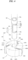
- FIG. 4 is an exploded perspective view of the rotating shaft 130 and the roller 144 of FIG. 2 .
- FIG. 5 is an assembled perspective view of the rotating shaft 130 and the roller 144 of FIG. 4 .
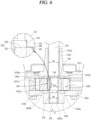
- FIG. 6 is a cross-sectional view of FIG. 5 .
- FIG. 7 is an enlarged sectional view of the rotation preventing unit 150 of FIG. 6 .
- an outer circumferential surface of the rotating shaft 130 and an inner circumferential surface of the shaft hole 1441, facing the outer circumferential surface of the rotating shaft 130 include the rotation preventing unit 150 configured to prevent rotation of the roller 144 with respect to the rotating shaft 130. Accordingly, even when the rotating shaft 130 and the roller 144 are separately manufactured, and then, post-assembled, rotational force of the driving motor 120 is transmitted to the roller 144 through the rotating shaft 130, and the roller 144 may rotate with the rotating shaft 130 to compress refrigerant.
- the rotation preventing unit 150 constrains the rotating shaft 130 and the roller 144 in a circumferential direction like being nearly coupled to each other, but not in an axial direction so that the rotating shaft 130 and the roller 144 are in a free state.
- the rotating shaft 130 and the roller 144 are nearly coupled to each other in a circumferential direction, but slidably coupled to each other in an axial direction.
- the rotating preventing unit 150 includes the rotation preventing groove 151 and the rotation preventing key 152.
- the rotation preventing groove 151 may be provided in an inner circumferential surface of the roller 144 and the rotation preventing key 152 may be provided on an outer circumferential surface of the rotating shaft 130 to face each other. However, on a contrary to this, the rotation preventing groove 151 may be provided in the outer circumferential surface of the rotating shaft 130 and the rotation preventing key 152 may be provided on the inner circumferential surface of the roller 144.
- a roller coupling unit 133 of the rotating shaft 130 which will be described later, is located between the main bearing unit 131 and the sub bearing unit 132, the former case may have more advantages compared to the latter case in terms of machining.
- the rotation preventing groove 151 is provided in the inner circumferential surface of the roller 144 and the rotation preventing key 152 is provided on the outer circumferential surface of the rotating shaft 130 is described.
- the rotation preventing groove 151 is provided to be radially recessed in the inner circumferential surface of the roller 144.
- the shaft hole 1441 may be provided at a center of the roller 144 such that the rotating shaft 130 is inserted into the shaft hole 1441, and the rotation preventing groove 151 described above is provided in the inner circumferential surface of the shaft hole 1441 to be radially recessed to a preset depth.
- the rotation preventing groove 151 is provided to terminate from the upper surface 144a to the lower surface 144b of the roller 144 in an axial direction. Accordingly, the rotation preventing groove 151 may be easily machined, and easily assembled into the rotation preventing key 152.
- the rotation preventing groove 151 may be provided to have a same cross-sectional area along an axial direction. Accordingly, the rotation preventing key 152 inserted into the rotation preventing groove 151 may also have a same cross-sectional area along an axial direction so that the roller 144 may smoothly move relative to the rotation shaft 130 in an axial direction.
- the rotation preventing groove 151 may be provided have a shape corresponding to the rotation preventing key 152 to be described later.
- the rotation preventing groove 151 may have a rectangular parallelepiped shape in which an axial length L21 is greater than a circumferential width L22.
- the rotation preventing groove 151 is provided to have a depth to overlap the rotation preventing key 152 to be described later in a circumferential direction. Accordingly, the rotation preventing key 152 to be described later may be slidably inserted into the rotation preventing groove 151 in the axial direction and the roller 144 may move relative to the rotating shaft 130 in an axial direction, but circumferential rotation of the roller 144 may be constrained so that the roller 144 may rotate together with the rotating shaft 130.
- the roller 144 is inserted into the cylinder 143, and an axial height H3 of the roller 144 may be provided to be slightly less than an axial height H4 of the cylinder 143, the axial height H4 being defined as a space between the main bearing 141 and the sub bearing 142. Accordingly, the upper surface 144a of the roller 144 may be spaced apart from the main sliding surface 1411a of the main bearing 141 and the lower surface 144b of the roller 144 may be spaced apart from the sub sliding surface 1421a of the sub bearing 142 by preset clearances, respectively.
- the roller 144 is provided to be movable relative to the cylinder 143 in an axial direction, in a state of being separate from the rotating shaft 130. Accordingly, a first clearance t1 between the upper surface 144a of the roller 144 and the main sliding surface 1411a of the main bearing 141, and a second clearance t2 between the lower surface 144b of the roller 144 and the sub sliding surface 1421a of the sub bearing 142 are generated, and oil flows into the clearances t1 and t2 to provide an oil film. Thus, friction loss and abrasion in the first and second clearances t1 and t2 may be suppressed.
- the rotation preventing key 152 protrudes from the outer circumferential surface of the rotating shaft 130 to the inner circumferential surface of the roller 144, in other words, toward the rotation preventing groove 151 included in the inner circumferential surface of the shaft hole 1441 by a preset height.
- the rotation preventing key 152 may extend integrally from the outer circumferential surface of the rotating shaft 130, or be post-assembled on the outer circumferential surface of the rotating shaft 130 to be coupled thereto. In this implementation, an example in which the rotation preventing key 152 is post-assembled on the outer circumferential surface of the rotating shaft 130 to be coupled thereto is described. Then, an example in which the rotation preventing key 152 extends integrally from the outer circumferential surface of the rotating shaft 130 will be described later as another implementation.
- the key accommodating groove 136 is provided in the outer circumferential surface of the rotating shaft 130 such that the rotation preventing key 152 is inserted and coupled into the key accommodating groove 136.
- the key accommodating groove 136 is provided between the main bearing unit 131 and the sub bearing unit 132 which will be described later. Accordingly, the rotation preventing key 152 may be slidably inserted in an axial direction into the rotation preventing groove 151 of the roller 144 included in the main bearing unit 131 and the sub bearing unit 132.
- the outer circumferential surface of the rotating shaft 130 includes the main bearing unit 131, the sub bearing unit 132, the roller coupling unit 133, and a roller support unit 134.
- the main bearing unit 131 is accommodated in the main bearing hole 1412a of the main bearing 141
- the sub bearing unit 132 is accommodated in a sub bearing hole 1422a of the sub bearing 142
- the roller coupling unit 133 is accommodated in the shaft hole 1441 of the roller 144.
- the roller support unit 134 is located between the main bearing unit 131 and the roller coupling unit 133.
- a part of the roller support unit 134 may be accommodated in the main bearing hole 1412a of the main bearing 141, and another part of the roller support unit 134 may be accommodated in the shaft hole 1441 of the roller 144.
- An outer diameter D1 of the man bearing unit 131 is provided to be greater than an outer diameter D3 of the roller coupling unit 133.
- the outer diameter D3 of the roller coupling unit 133 is provided to be greater than an outer diameter D2 of the sub bearing unit 132. Accordingly, the roller 144 may be inserted in a direction from a lower end of the rotating shaft 130, i.e., a lower end of the sub bearing unit 132 toward the main bearing unit 131.
- an outer diameter D4 of the roller support unit 134 located between the main bearing unit 131 and the roller coupling unit 133 is less than the outer diameter D1 of the main bearing unit 131 and greater than the outer diameter D3 of the roller coupling unit 133. Accordingly, with reference to a portion between the roller coupling unit 133 and the roller support unit 134, i.e., an axial direction center of the roller 144, a roller support surface 135 may be provided to have a height difference at a side adjacent to the driving motor 120.
- the roller support surface 135 may be provided to have an annular shape.
- the roller support surface 135 may be provided to have an annular shape having a same width along a circumferential direction. Accordingly, the rotating shaft 130 and the roller 144 may be uniformly in contact with each other on the roller support surface 135 along a circumferential direction so that the rotating shaft 130 may be stably supported by the roller 144, or the roller 144 may be stably supported by the rotating shaft 130.
- the roller support surface 135 may be provided along a circumferential direction at a preset interval.
- the roller support surface 135 may be provided such that the roller 144 is located in a middle portion between the main bearing 141 and the sub bearing 142 in a state when the stator 121 and the rotor 122 are aligned with each other due to magnetic centering.
- the roller support surface 135 may be provided in a position in which the first clearance t1 between the roller 144 and the main bearing 141 nearly matches the clearance t2 between the roller 144 and the sub bearing 142 in a state when a center of the stator 121 is arranged with that of the rotor 122.
- the roller 144 is located approximately at a center between the main bearing 141 and the main bearing 142. Then, the roller 144 may maintain a state of not being in contact with the main bearing 141 and the sub bearing 142, thus minimizing friction loss or abrasion between the roller 144 and both of the main bearing 144 and the sub bearing 141.
- the roller support surface 135 of the rotating shaft 130 is placed on an upper axial surface of the roller 144 to support the rotating shaft 130 in an axial direction.
- the key accommodating groove 136 is provided in an outer circumferential surface of the roller coupling unit 133 such that the rotation preventing key 152 is inserted and fixed into the key accommodating groove 136. Accordingly, the rotating shaft 130 may be easily machined, and the rotation preventing key 152 may be also easily provided on the rotating shaft 130.
- the key accommodating groove 136 is provided longitudinally in an axial direction to correspond to the rotation preventing key 152.
- an axial length L1 of the key accommodating groove 136 according to this implementation may be equal to or slightly greater than an axial length L21 of the rotation preventing key 152. Accordingly, the rotation preventing key 152 may be easily assembled into the key accommodating groove 136.
- the key accommodating groove 136 may be provided to have a constant size along an axial direction. For example, a circumferential width and a radial depth of the key accommodating groove 136 may be provided to be constant along the axial direction. Thus, the key accommodating groove 136 may be easily machined, and assembly stability of the rotation preventing key 152 inserted into the key accommodating groove 136 may be enhanced. By doing so, rotational force may be stably and uniformly transmitted through the rotation preventing key 152.
- the rotation preventing key 152 is inserted and coupled into the key accommodating groove 136 described above.
- the rotation preventing key 152 may be press-fit and fixed into the key accommodating groove 136.
- the rotation preventing key 152 may be fixedly coupled to the key accommodating groove 136 by an adhesive.
- the rotation preventing key 152 may include a same material as that of the rotating shaft 130 or a material having rigidity or hardness similar to that of the rotating shaft 130. Accordingly, the rotation preventing key 152 may transmit the rotational force to the roller 144 without being damaged in a state of being inserted into the key accommodating groove 136.
- the rotation preventing key 152 may include a material different from that of the rotating shaft 130.
- the rotation preventing key 152 may include a material having less rigidity or hardness compared to the rotating shaft 130.
- the outer circumferential surface of the rotation preventing key 152 may be coated with a material having greater rigidity or hardness compared to the rotation preventing key 152 or a separate sliding member (not shown) may surround the rotation preventing key 152 to be coupled thereto. Accordingly, freedom of material selection for the rotation prevention key 152 may be increased, and rigidity of the rotation prevention key 152 may be also ensured.
- the rotation preventing key 152 may have a shape corresponding to the rotation preventing groove 151, e.g., a rectangular parallelepiped shape in which an axial length L31 is greater than a circumferential width L32. Accordingly, a circumferential area of the rotation preventing key 152 (or the rotation preventing groove) between the vane slots 1446a, 1446b, and 1446c may be minimized, and rotational force may also be uniformly transmitted to the roller 144 in the axial direction.
- the rotation preventing key 152 may have a size same as or smaller than the rotation preventing groove 151.
- the axial length L31 of the rotation preventing key 152 may be provided to be equal to or less than the axial length L21 of the rotation preventing groove 151. Accordingly, an axial moving distance of the rotating shaft 130 may be ensured to be greater than that of the roller 144.
- the axial length L31 of the rotation preventing key 152 may be equal to or less than the axial length L21 of the rotation preventing groove 151.
- the axial length L31 of the rotation preventing key 152 may be provided to be about 0.5 times less than the axial length L21 of the rotation preventing groove 151. Accordingly, even when the rotating shaft 130 axially moves toward the stator 121 with the rotor 122 that is magnetic-centered, an upper end of the rotation preventing key 152 may be prevented from coming in contact with the main sliding surface 1411a of the main bearing 141.
- the circumferential length L32 of the rotation preventing key 152 may be provided to be less than the circumferential length L22 of the rotation preventing groove 151. Accordingly, the outer circumferential surface of the rotation preventing key 152 may be inserted into the inner circumferential surface of the rotation preventing groove 151 to slide in an axial direction (refer to FIG. 3 ).
- an radial length H2 of the rotation preventing key 152 may be provided to be about two times or greater than the radial depth H1 of the key accommodating groove 136. Accordingly, when the rotation preventing key 152 is inserted into the rotation preventing groove 151, a part of an outer circumference of the rotation preventing key 152 protrudes, and the protruding part of the outer circumference is inserted into the rotation preventing groove 151 of the roller 141 to be described later. Thus, the rotating shaft 130 and the roller 144 may stably constrain each other with respect to a circumferential direction.
- the rotation preventing key 152 may be provided to have a rectangular parallelepiped shape having a great axial length, and a sliding surface 152a may be provided respectively at upper and lower ends of the rotation preventing key 152.
- a sliding surface 152a may be provided respectively at circumferential corners of the upper and lower ends of the rotation preventing key 152.
- abrasion between a lower corner of the rotation preventing key 152 and the sub sliding surface 1412a of the sub bearing 142, facing the lower corner of the rotation preventing key 512 may be suppressed when the compressor is started in a descending state of the rotating shaft 130, or abrasion between the upper corner of the rotation preventing key 152 and the main sliding surface 1411a of the main bearing 141, facing the upper corner of the rotation preventing key 152, may be suppressed when the compressor is started in an ascending state of the rotating shaft 130.
- the outer circumferential surface of the rotating shaft 130 and the inner circumferential surface of the roller 144 may be provided to have a D-cut section to match each other.
- the separate rotation preventing key 152 and rotation preventing groove 151, described above, may not be provided.
- FIG. 8A is a cross-sectional view illustrating a relation between the rotating shaft and the roller in a stop state of the compressor.
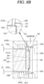
- FIG. 8B is a cross-sectional view illustrating a relation between the rotating shaft and the roller in an operation state of the compressor.
- a clearance between the roller and both of the bearings is exaggerated for convenience of description.
- the first clearance t1 between the upper surface 144a of the roller 144 and the main sliding surface 1411a is nearly equal to an axial height difference between the roller 144 and the cylinder 143
- the second clearance t2 between the lower surface 144b of the roller 144 and the sub sliding surface 1421a is nearly 0 (zero).
- the rotating shaft 130 is axially supported.
- the roller 144 descends separately from the rotating shaft 130 due to a dead weight, and thus, the lower surface 144b of the roller 144 is supported by the sub sliding surface 1421a of the sub bearing 142.
- the rotor 122 when the compressor is in an operation state, the rotor 122 ascends according magnetic centering so that a center of the rotor 122 and a center of the stator 121 are aligned to have a same height.
- the rotation preventing key 152 is axially in a free state with respect to the rotation preventing groove 151, the rotating shaft 130 slidably ascends in an axial direction relative to the roller 144.
- the roller 144 ascends separately from the rotating shaft 130 according to pressure of oil filled in the first sub back pressure pocket 1425a and the second sub back pressure pocket 1425b, both included in the sub bearing 142.
- oil is also filled in the first main back pressure pocket 1415a and the second main back pressure pocket 1415b, both included in the main bearing 141, and an ascending amount of the roller 144 is limited by the oil pressure.
- the roller 144 is spaced apart from the main bearing 141 and the sub bearing 142 due to pressure of the oil filled in the back pressure pockets 1415a and 1415b, and 1425a and 1425b of both of the bearings 141 and 142.
- a first clearance t1' between the upper surface 144a of the roller 144 and the main sliding surface 1411a is nearly equal to a second clearance t2' between the lower surface 144b of the roller 144 and the sub sliding surface 1421a.
- the rotating shaft is axially supported in a stop state of the compressor, and the roller is spaced apart from a main bearing and a sub bearing in an operation state of the compressor.
- friction loss or abrasion between the roller and the main and sub bearings may be effectively suppressed.
- a distance between the roller and the main bearing or between the roller and the sub bearing is constantly maintained.
- a leak between compression chambers or oil leakage from a back pressure pocket through a gap between the roller and the bearings is suppressed to thereby enhance compression efficiency or volumetric efficiency.
- the rotation preventing key since a rotation preventing key is inserted and post-assembled into a key accommodating groove in the rotating shaft, the rotation preventing key may be easily provided. Also, an assembly structure of the roller and the rotating shaft may be simplified.
- roller rotates with the rotating shaft and the roller is slidably coupled to the rotating shaft, a tolerance between the roller and the rotating shaft may be ensured. Accordingly, after the roller and the rotation shaft are post-assembled, post-machining such as grinding may not be performed, and an assembly structure of the roller and the rotating shaft may be simplified.
- a single-stage rotation preventing key is inserted and coupled into a key accommodating groove.
- a multi-stage rotation preventing key may be inserted and coupled into the key accommodating groove.
- FIG. 9 is an exploded perspective view illustrating another implementation of the rotation preventing key 152 of FIG. 1 .
- FIG. 10 is an assembled cross-sectional view of the implementation of FIG. 9 .
- a basic configuration of the rotation preventing groove 151 and the rotation preventing key 152 both included in the rotation preventing unit 150 according to this implementation, and an effect resulting therefrom may be nearly identical to those of the implementation described above.
- the key accommodating groove 136 may be provided in the rotating shaft 130, and the rotation preventing key 152 is inserted and coupled into the key accommodating groove 136.
- the rotation preventing key 152 is slidably inserted and coupled into the rotation preventing groove 151 in the inner circumferential surface of the roller 144 in an axial direction.
- the rotation preventing groove 151 and the rotation preventing key 152 may constrain each other in a circumferential direction, and be in a free state within a certain range in an axial direction.
- the description about the implementation described above may be referred to.
- the key accommodating groove 136 may be provided in multi-stages, and the rotation preventing key 152 may be also provided in multi-stages to correspond to the key accommodating groove 136.
- a fixing groove 1511 may be provided at a center of the key accommodating groove 136, and a fixing pin 1521 may be provided on one radial side surface of the rotation preventing key 152, and inserted and coupled into the fixing groove 1511.
- the fixing groove 1511 and the fixing pin 1521 may be provided to correspond to each other such that the fixing pin 1521 is inserted into the fixing groove 1511.
- an inner diameter of the fixing groove 1511 may be provided to be nearly equal to an outer diameter of the fixing pin 1521. Accordingly, the fixing pin 1521 may be press-fit into the fixing groove 1511.
- the key preventing key 152 may maintain a state of being inserted into the key accommodating groove 136. By doing so, assembling of the rotation preventing key 152 may be simplified.
- a roller and a rotating shaft include a same material.
- the roller and the rotating shaft may be provided to include different materials.
- FIG. 11 is an exploded perspective view illustrating another implementation of the roller of FIG. 1 .
- FIG. 12 is a planar view of a rotation preventing unit of FIG. 11 .
- a basic configuration of the rotation preventing groove 151 and the rotation preventing key 152 both included in the rotation preventing unit 150 according to this implementation, and an effect resulting therefrom may be nearly identical to that of the implementation described above.
- the key accommodating groove 136 may be provided in the rotating shaft 130, and the rotation preventing key 152 is inserted and coupled into the key accommodating groove 136.
- the rotation preventing key 152 is slidably inserted and coupled into the rotation preventing groove 151 provided in the inner circumferential surface of the roller 144 in an axial direction.
- the rotation preventing groove 151 and the rotation preventing key 152 may constrain each other in a circumferential direction, and be in a free state within a certain range in an axial direction.
- the implementation described above may be referred to.
- the roller 144 and the rotating shaft 130 may be provided to include different materials.
- the rotating shaft 130 includes stainless steel
- the roller 144 may include a material lighter than that of the rotating shaft 130, that is, a material lighter than stainless steel. Accordingly, by reducing a whole weight of the rotating shaft 130 including the roller 144 by reducing a weight of the roller 144, motor efficiency may be enhanced.
- the roller 144 may just need to include a material lighter than the rotating shaft. However, considering that the roller 144 is coupled to the rotation preventing key 152 of the rotating shaft 130, the roller 144 may be provided to include a material with high rigidity as possible to ensure reliability.
- a first reinforcing member 153 may be provided between the rotation preventing groove 151 and the rotation preventing key 152.
- the first reinforcing member 153 may be provided to include a material having higher rigidity or hardness compared to the roller 144.
- the roller 144 may include a light material and the rotation preventing groove 151 may be prevented from being crushed. By doing so, a state of coupling between the rotation preventing groove 151 and the rotation preventing key 152 may be stably maintained.
- the rotation preventing groove 151 may be provided in the inner circumferential surface of the roller 144 according to this implementation, and a reinforcing member including a material different from engineering plastic may be inserted into the inner circumferential surface of the rotation preventing groove 151.
- the roller 144 may include engineering plastic
- the first reinforcing member 153 may include a material having higher rigidity or hardness compared to engineering plastic.
- the first reinforcing member 153 may include stainless steel same as that of the rotating shaft 130.
- the first reinforcing member 153 is provided to have a same cross-sectional shape as that of an inner circumferential surface of the rotation preventing groove 151 to be press-fit or attached to be coupled thereto.
- a step surface (no reference numeral) is provided at a lower end of the rotation preventing groove 151 to axially support a lower end of the first reinforcing member 153.
- the first reinforcing member (not shown) may be inserted into the outer circumferential surface of the rotation preventing key 152.
- the roller 144 may be manufactured using a light material and the rotation preventing groove 151 may be prevented from being crushed to stably maintain a state of coupling between the rotation preventing groove 151 and the rotation preventing key 152.
- the roller 144 and the rotating shaft 130 may be manufactured using a material lighter than the rotating shaft 130. By doing so, a weight of the roller 144 may be reduced to decrease a load on a motor, thereby enhancing performance of the compressor.
- the first reinforcing member 153 having high rigidity or hardness may be provided on the outer circumferential surface of the rotation preventing key 152 or the inner circumferential surface of the rotation preventing groove 151.
- the roller 144 may include a material lighter than the rotating shaft 130, and a coupling reliability between the roller 144 and the rotating shaft 130 may be ensured.
- a plurality of the vane slots 1446a, 1446b, and 1446c may be provided in the outer circumferential surface of the roller 144, and second reinforcing members 1448a, 1448b, and 1448c may be press-fit or attached to be coupled to the vane slots 1446a, 1446b, and 1446c.
- the second reinforcing members 1448a, 1448b, and 1448c may be provided to include a material having rigidity or hardness higher than the roller 144. Accordingly, the roller 144 may include a material lighter than the rotating shaft 130, and vanes constituting a compression chamber may be stably supported.
- a roller support surface is provided on a rotating shaft.
- a hooking surface may be provided on a roller.
- FIG. 13 is a fractured perspective view illustrating another implementation of the rotation preventing groove 151 of FIG. 1 .
- FIG. 14A is a cross-sectional view illustrating a relation between the rotating shaft 130 and the roller 144 in a stop state of the compressor of FIG. 13 .
- FIG. 14B is a cross-sectional view illustrating a relation between the rotating shaft 130 and the roller 144 in an operation state of the compressor of FIG. 13 .
- a basic configuration of the rotation preventing groove 151 and the rotation preventing key 152 both included in the rotation preventing unit 150 according to this implementation, and an effect resulting therefrom may be nearly identical to that of the implementation described above.
- the key accommodating groove 136 may be provided in the rotating shaft 130, and the rotation preventing key 152 is inserted and coupled into the key accommodating groove 136.
- the rotation preventing key 152 is slidably inserted and coupled into the rotation preventing groove 151 in the inner circumferential surface of the roller 144 in an axial direction.
- the rotation preventing groove 151 and the rotation preventing key 152 may constrain each other in a circumferential direction, and be in a free state within a certain range in an axial direction.
- the description about the implementation described above may be referred to.
- a hooking surface 1512 for axially constraining the rotation preventing groove 151 to the rotation preventing key 152 may be provided.
- an upper end of the rotation preventing groove 151 adjacent to the stator 121 may be open in an axial direction, but a lower end thereof apart from the stator 121 may be closed in an axial direction.
- the roller support unit 134 and the roller support surface 135 may not be provided on the outer circumferential surface of the rotating shaft 130.
- the hooking surface 1512 may be provided in the rotation preventing groove 151, and the roller support surface 135 may be provided on the rotating shaft 130 together. In this case, the rotating shaft 130 and the roller 144 may be stably supported.
- a rotation preventing key is assembled on a rotating shaft.
- the rotation preventing key may be provided integrally on the rotating shaft.
- FIG. 15 is a perspective view illustrating another implementation of the rotation preventing key 152 of FIG. 1 .
- FIG. 16 is a planar view of FIG. 15 .
- a basic configuration of the rotation preventing groove 151 and the rotation preventing key 152 both included in the rotation preventing unit 150 according to this implementation, and an effect resulting therefrom may be nearly identical to that of the implementations described above.
- specifications of the rotation preventing groove 151 and the rotation preventing key 152 are nearly identical to those in the implementations described above.
- the description about the implementation described above may be referred to.
- the rotation preventing key 152 extend from the outer circumferential surface of the rotating shaft 130 in a radial direction.
- the rotation preventing key 152 extends to axially protrude from the roller coupling unit 133 of the rotating shaft 130, and extend longitudinally in an axial direction. Accordingly, the rotation preventing key 152 of the rotating shaft 130 is inserted into the rotation preventing groove 151 of the roller 144 to constrain a circumferential direction between the roller 144 and the rotating shaft 130.
- a root portion (no reference numeral) of the rotation preventing key 152 extending from the outer circumferential surface of the rotating shaft 130 may be curvedly provided. By doing so, the root portion of the rotation preventing key 152 may be suppressed from being damaged due to concentration of stress on the root portion.
- the rotation preventing key 152 when the rotation preventing key 152 is provided integrally with the rotating shaft 130, the rotation preventing key 152 may not need to be assembled into the rotating shaft 130 separately. Thus, a working man hour for the rotation preventing unit 1150 including the rotation preventing key 152 and the rotation preventing groove 151 may be reduced.
- the rotation preventing key 152 and the rotation preventing groove 151 may be provided in plurality of pairs at uniform intervals along the circumferential direction.
- the roller 144 may be firmly coupled to the rotating shaft 130 to stably transmit a rotational force of the rotating shaft 130 to the roller 144.
- a discharge port may not be provided on the main bearing 141 and the sub bearing 142, but on the cylinder 143.
- the rotating shaft 130 described above may be slidably coupled to the roller 144.
Landscapes
- Engineering & Computer Science (AREA)
- Mechanical Engineering (AREA)
- General Engineering & Computer Science (AREA)
- Applications Or Details Of Rotary Compressors (AREA)
Abstract
Description
- This disclosure relates to a rotary compressor in which a rotating shaft is assembled with a roller.
- A rotary compressor is classified into a rotary compressor type in which a vane is slidably inserted into a cylinder to be in contact with a roller, and a rotary compressor type in which a vane is slidably inserted into a roller to be in contact with a cylinder. In general, the former is called a rotary compressor with an eccentric roller (hereinafter referred to as a "rotary compressor"), and the latter is called a concentric vane rotary compressor (hereinafter referred to as a "vane rotary compressor").
- As for a rotary compressor, a vane inserted in a cylinder is pulled out toward a roller by elastic force or back pressure to come into contact with an outer circumferential surface of the roller. On the other hand, for a vane rotary compressor, a vane inserted in a roller rotates together with the roller, and is pulled out by centrifugal force and back pressure to come into contact with an inner circumferential surface of a cylinder.
- A rotary compressor independently forms as many compression chambers as the number of vanes per revolution of a roller, and the compression chambers simultaneously perform suction, compression, and discharge strokes. On the other hand, a vane rotary compressor continuously forms as many compression chambers as the number of vanes per revolution of a roller, and the compression chambers sequentially perform suction, compression, and discharge strokes. Therefore, the vane rotary compressor provides a higher compression ratio than the rotary compressor. Therefore, the vane rotary compressor is more suitable for high pressure refrigerants such as R32, R410a, and CO2, which have low ozone depletion potential (ODP) and global warming index (GWP).
- The vane rotary compressor is generally configured such that a center of the roller matches a center of the rotating shaft. Thus, the vane rotary compressor may be referred to as a concentric vane-type rotary compressor. Hereinafter, the concentric vane-type rotary compressor is defined as a vane rotary compressor in the description.
- The vane rotary compressor is disclosed in patent document 1 (Japanese Patent Publication No.:
JP 2013-072429A JP 2013-050038A patent document 1 discloses an example in which a roller is manufactured integrally with a rotating shaft. - The patent document 2 discloses an example in which a roller and a rotating shaft are separately manufactured, and then, post-assembled with each other. In this case, an outer circumferential surface of the rotating shaft and an inner circumferential surface of the roller are provided to have a circular shape to be press-fit, or machined to have a serration or gear shape to be pressed or press-fit. Alternatively, the roller and the rotating shaft may be coupled to each other using a fixing pin penetrating therethrough.
- However, as described above, when the roller is manufactured integrally or post-assembled, the rotating shaft and the roller are provided as a single body. Thus, when magnetic centering such that a rotor is aligned with a center of a stator is performed, the roller axially moves with the rotating shaft coupled to the rotor. Then, as one axial side surface of the roller (i.e., an upper bearing surface) is brought into close contact with a thrust surface of a main bearing facing the upper bearing surface, friction loss or abrasion occurs. In addition, as a gap between the roller and a sub bearing is enlarged in correspondence with raising of the roller, leakage between compression chambers occurs, thereby deteriorating compression efficiency.
- In addition, when the rotating shaft and the roller are manufactured as a single body as described above, the rotating shaft and the roller are manufactured using a same material. When the rotating shaft and the roller are separately machined and post-assembled as a single body, the rotating shaft and the roller are also manufactured using a same material or materials having similar rigidity and hardness in consideration of coupling reliability. Thus, as there are limits in selecting a material of the roller and reducing a weight of the roller, motor efficiency may not be increased.
- In addition, as described above, when the rotating shaft and the roller are post-assembled as a single body, since a change in a post-assembly process may occur, the rotating shaft and the roller are assembled, and then, post-machined. In other words, primary processing of separately machining the rotating shaft and the roller is performed, then, the rotating shaft and the roller on which the primary machining is performed are post-assembled, and then, secondary machining of grinding a vane slot and a cross section and an outer circumferential surface with respect to the roller is performed. Thus, as machining time increases, a manufacture cost may increase.
- It is an object of the present disclosure to provide a rotary compressor configured to suppress friction loss or abrasion between a roller and a bearing axially facing the roller, and also suppress leakage between compression chambers through a gap between the roller and a sub bearing.
- It is an object of the present disclosure to provide a rotary compressor in which the roller is post-assembled with a rotating shaft and the roller is coupled to perform a relative motion with respect to the rotating shaft.
- It is an object of the present disclosure to provide a rotary compressor in which the roller may perform a relative motion with respect to the rotating shaft and a relative motion range of the roller may be limited.
- It is an object of the present disclosure to provide a rotary compressor in which a roller and a rotating shaft are post-assembled, and an assembly structure of the rotating shaft may be simplified.
- It is an object of the present disclosure to provide a rotary compressor in which the roller and the rotating shaft are post-assembled, and the roller or the rotating shaft may be easily machined.
- It is an object of the present disclosure to provide a rotary compressor in which a tolerance of the roller and the rotating shaft is ensured so that post-machining after post-assembly may not be performed.
- It is an object of the present disclosure to provide a rotary compressor such that a weight of the roller may be reduced to increase compression efficiency.
- It is an object of the present disclosure to provide a rotary compressor in which the roller and the rotating shaft may include different materials to reduce a weight of the roller.
- It is an object of the present disclosure to provide a rotary compressor in which the roller and the rotating shaft include different materials, but coupling reliability is enhanced.
- The object is solved by the features of the independent claims. Preferred embodiments are given in the dependent claims.
- According to the present disclosure, a rotary compressor may include a casing, a driving motor, a rotating shaft, a main bearing and a sub bearing, a cylinder, a roller, a vane, and a rotation preventing unit. The driving motor may be included inside the casing. The rotating shaft may be coupled to a rotor in the driving motor and transmit rotational force. The main bearing and the sub bearing may support the rotating shaft. The cylinder may be provided between the main bearing and the sub bearing to provide a compression space. The roller may be provided with a shaft hole through which the rotating shaft penetrates and is inserted in an axial direction. The vane may divide the compression space into a plurality of compression chambers. The rotation preventing unit may be provided between an outer circumferential surface of the rotating shaft and an inner circumferential surface of an shaft hole in the roller, the inner circumferential surface facing the outer circumferential surface of the rotating shaft, to constrain rotation of the roller with respect to the rotating shaft. The rotation preventing unit may allow axial movement of the roller with respect to the rotating shaft. Thus, axial movement of the roller along a rotating shaft may be suppressed, and friction loss and abrasion between the roller and a main bearing or between the roller or a sub bearing may be suppressed.
- As an example, the rotation preventing unit may include a rotation preventing groove and a rotation preventing key.
- The rotation preventing groove may be provided in an inner circumferential surface of the shaft hole.
- The rotation preventing key may be provided on the outer circumferential surface of the rotating shaft and slidably inserted into the rotation preventing groove in an axial direction.
- The rotation preventing key may be post-assembled on the rotating shaft. Thus, the rotation preventing key constituting the rotation preventing unit may be easily provided on the rotating shaft.
- In detail, a key accommodating groove may be provided in the outer circumferential surface of the rotating shaft.
- The rotation preventing key may be inserted and coupled into the key accommodating groove. Thus, the rotation preventing key may be easily coupled to the rotating shaft, and coupling stability may be also enhanced.
- As another example, the rotation preventing unit may include a rotation preventing groove and a rotation preventing key.
- The rotation preventing groove may be provided in an inner circumferential surface of the shaft hole.
- The rotation preventing key may be provided on the outer circumferential surface of the rotating shaft and slidably inserted into the rotation preventing groove in an axial direction.
- The rotation preventing key may extend integrally from the rotating shaft. Thus, assembly of the rotation preventing unit including the rotation preventing key may be simplified.
- As another example, the rotation preventing unit may include a rotation preventing groove and a rotation preventing key.
- The rotation preventing groove may be provided in an inner circumferential surface of the shaft hole.
- The shaft hole may be also called axial hole and extends in radial direction through the roller.
- The rotation preventing key may be provided on the outer circumferential surface of the rotating shaft and slidably inserted into the rotation preventing groove in an axial direction.
- An axial length of the rotation preventing key may extend longer than a circumferential width of the rotation preventing key. Thus, a circumferential area of the rotation preventing key may be greatly reduced, and rotational force may be stably transmitted to the roller.
- In detail, the axial length of the key accommodating key may be provided to be equal to or less than an axial length of the rotation preventing groove.
- Thus, during axial movement of the rotating shaft, the rotation preventing key may be suppressed from being hooked on a main bearing or a sub bearing.
- As another example, the outer circumferential surface of the rotating shaft may be provided with a roller support surface configured to limit the axial movement of the roller and have a height difference relative to the outer circumferential surface of the rotating shaft.
- Thus, the rotating shaft may be axially supported by the roller to enhance assembly stability and, simultaneously, limit axial movement of the roller to suppress friction loss and abrasion between the roller and a bearing.
- In detail, the roller support surface may be arranged adjacent to the driving motor with reference to an axial center of the roller. Thus, excessive ascending of the roller toward a main bearing located at an upper side may be suppressed to reduce friction loss and abrasion between the roller and the main bearing.
- In detail, the roller support surface may be provided to have an annular shape. Thus, the rotating shaft and the roller are uniformly supported in a circumferential direction to stably support the rotating shaft or the roller in an axial direction.
- As another example, the rotation preventing unit may include a rotation preventing groove and a rotation preventing key.
- The rotation preventing groove may be provided in an inner circumferential surface of the shaft hole. The rotation preventing key may be arranged on the outer circumferential surface of the rotating shaft and slidably inserted into the rotation preventing groove in an axial direction.
- One axial end of the rotation preventing groove may be open and another axial end thereof may be closed to provide a hooking surface to limit axial movement of the rotation preventing key. Thus, the rotating shaft may be axially supported by the roller to enhance assembly stability and, simultaneously, limit axial movement of the roller to suppress friction loss and abrasion between the roller and a bearing.
- In detail, the hooking surface may be provided at an end portion far apart from the driving motor with reference to the axial center of the roller. Thus, excessive ascending of the roller toward a main bearing located at an upper side may be suppressed to reduce friction loss and abrasion between the roller and the main bearing.
- As another example, the roller may include a material having lower rigidity or hardness compared to the rotating shaft. Thus, a weight of the roller may be reduced, thereby reducing load on the driving motor.
- In detail, the rotation preventing unit may include a rotation preventing groove and a rotation preventing key.
- The rotation preventing groove may be provided in an inner circumferential surface of the shaft hole.
- The rotation preventing key may be provided on the outer circumferential surface of the rotating shaft and slidably inserted into the rotation preventing groove in an axial direction.
- A first reinforcing member is provided between an inner circumferential surface of the rotation preventing groove and an outer circumferential surface of the rotation preventing key.
- The first reinforcing member may include a material having higher rigidity or hardness compared to the roller. Thus, the roller may include a material lighter than that of the rotating shaft, and abrasion resistance may be also increased to ensure reliability of the rotation preventing unit.
- In detail, a vane slot may be provided in an outer circumferential surface of the roller, the vane being inserted into the vane slot.
- A second reinforcing member is inserted into the vane slot.
- The second reinforcing member may include a material having higher rigidity or hardness compared to the roller. Thus, the roller may include a light material, and abrasion resistance between the vane and the vane slot may be also increased to ensure compressor performance.
- As still another example, a back pressure pocket communicating with the inside of the casing may be on at least one from among a sliding surface of the main bearing and a sliding surface of the sub bearing, the sliding surface of the main bearing facing one axial side surface of the roller and a sliding surface of the sub bearing facing another axial side surface of the roller. Therefore, excessive axial movement of the roller due to pressure of oil in the back pressure pocket may be suppressed, and thus, friction loss and abrasion between the roller and a bearing facing the roller may be suppressed.
- In detail, the back pressure pocket may at least partially overlap the rotation preventing unit in an axial direction. Thus, the oil in the back pressure pocket may flow into the rotation preventing unit to smoothly lubricate between the rotation preventing groove and the rotation preventing key both included in the rotation preventing unit.
- In the rotary compressor according to the present disclosure, the inner circumferential surface of the cylinder may be formed in an elliptical shape.
- In the rotary compressor according to the present disclosure, the inner circumferential surface of the cylinder may be formed in a circular shape.
-
-
FIG. 1 a cross-sectional view illustrating one implementation of a vane rotary compressor of the disclosure. -
FIG. 2 is an exploded perspective view illustrating a compression unit ofFIG. 1 . -
FIG. 3 is an assembled planar view of the compression unit inFIG. 2 . -
FIG. 4 is an exploded perspective view of a rotating shaft and a roller inFIG. 2 . -
FIG. 5 is an assembled perspective view of the rotating shaft and the roller inFIG. 4 . -
FIG. 6 is a cross-sectional view ofFIG. 5 . -
FIG. 7 is an enlarged sectional view of a rotation preventing unit ofFIG. 6 . -
FIG. 8A is a cross-sectional view illustrating a relation between the rotating shaft and the roller in a stop state of the compressor. -
FIG. 8B is a cross-sectional view illustrating a relation between the rotating shaft and the roller in an operation state of the compressor. -
FIG. 9 exploded perspective view illustrating another implementation of a rotation preventing key ofFIG. 1 . -
FIG. 10 is an assembled cross-sectional view ofFIG. 9 . -
FIG. 11 is an exploded perspective view illustrating another implementation of the roller ofFIG. 1 . -
FIG. 12 is a planar view of an assembled state of a rotation preventing unit ofFIG. 11 . -
FIG. 13 is a fractured perspective view illustrating another implementation of a rotation preventing groove ofFIG. 1 . -
FIG. 14A is a cross-sectional view illustrating a relation between the rotating shaft and the roller in a stop state of a compressor ofFIG. 13 . -
FIG. 14B is a cross-sectional view illustrating a relation between the rotating shaft and the roller in an operation state of the compressor ofFIG. 13 . -
FIG. 15 is a perspective view illustrating another implementation of the rotation preventing key ofFIG. 1 . -
FIG. 16 is a planar view ofFIG. 15 . - Description will now be given in detail of a vane rotary compressor according to exemplary implementations disclosed herein, with reference to the accompanying drawings.
- The present disclosure provides a roller assembled with a rotating shaft and coupled thereto to be movable in an axial direction within a certain range. This may apply to not only a vane rotary compressor in which a vane is slidably inserted into a roller, but also a general rotary compressor in which a vane is slidably inserted into a cylinder. Hereinafter, a vane rotary compressor is described as a representative example.
-
FIG. 1 is a cross-sectional view illustrating one implementation of the vane rotary compressor according to the present disclosure,FIG. 2 is an exploded perspective view illustrating a compression unit ofFIG. 1 , andFIG. 3 is an assembled planar view of the compression unit inFIG. 2 . - Referring to
FIG. 1 , a vane rotary compressor according to this implementation includes acasing 110, a driving (or drive)motor 120, arotating shaft 130, and acompression unit 140. The drivingmotor 120 is installed in an upper (a first)inner space 110a of thecasing 110, and thecompression unit 140 is installed in a lower (a second)inner space 110a of thecasing 110. The drivingmotor 120 and thecompression unit 140 are connected through arotating shaft 130. - The
casing 110 that defines an outer appearance of the compressor may be classified as a vertical type and a horizontal type according to a compressor installation method. As for the vertical type casing, the drivingmotor 120 and thecompression unit 140 are disposed at upper and lower sides in an axial direction, respectively. As for the horizontal type casing, the drivingmotor 120 and thecompression unit 140 are disposed at left and right sides, respectively. The casing according to this implementation may be illustrated as the vertical type. Thus, the drivingmotor 120 and thecompression unit 140 may also disposed in a first and second inner space of the casing respectively. - The
casing 110 includes anintermediate shell 111 having a cylindrical shape, a lower (second)shell 112 covering a lower (second) end of theintermediate shell 111, and an upper (first)shell 113 covering an upper (second) end of theintermediate shell 111. In the following the terms lower and upper will be used in view of the illustration in the drawings. However, the lower and upper shell may be also designated second and first shell, respectively. - The driving
motor 120 and thecompression unit 140 may be inserted into theintermediate shell 111 to be fixed thereto. Asuction pipe 115 may penetrate through theintermediate shell 111 to be directly connected to thecompression unit 140. Thelower shell 112 may be coupled to the lower end of theintermediate shell 111 in a sealing manner. Anoil storage space 110b in which oil to be supplied to thecompression unit 140 is stored may be formed mainly in thelower shell 112 below thecompression unit 140. - The
upper shell 113 may be coupled to the upper end of theintermediate shell 111 in a sealing manner. Anoil separation space 110c may be formed above the drivingmotor 120 to separate oil from refrigerant discharged from thecompression unit 140. - The driving
motor 120 that constitutes a motor unit supplies power to cause thecompression unit 140 to be driven. The drivingmotor 120 includes a stator 121 and arotor 122. - The stator 121 may be fixedly inserted into the
casing 110. The stator 121 may be fixed to an inner circumferential surface of thecasing 110 in a shrink-fitting manner or the like. For example, the stator 121 may be press-fitted into an inner circumferential surface of theintermediate shell 111. - The
rotor 122 may be rotatably inserted into the stator 121, and therotating shaft 130 may be press-fitted into a center of therotor 122. Accordingly, therotating shaft 130 rotates concentrically together with therotor 122. - An
oil flow path 130a having a hollow hole shape is provided in a central portion of therotating shaft 130. Oil passage holes 130b and 130c are provided through a middle portion of theoil flow path 130a toward an outer circumferential surface of therotating shaft 130. The oil passage holes 130b and 130c include a firstoil passage hole 130b belonging to a range of a main bush portion 1412 to be described later and a secondoil passage hole 130c belonging to a range of asub bush portion 1422. Each of the firstoil passage hole 130b and the secondoil passage hole 130c may be provided by one or in plurality. In this implementation, the first and second oil passage holes 130b, 130c are respectively provided in plurality. - An
oil pickup 130d may be installed in a middle portion or a lower end of theoil flow path 130a. A gear pump, a viscous pump, a centrifugal pump, or the like may be used for theoil pickup 130d. In this implementation, a case in which the centrifugal pump is employed is illustrated. Accordingly, when therotating shaft 130 rotates, oil filled in theoil storage space 110b is pumped by theoil pickup 130d and is sucked along theoil flow path 130a to be supplied into a sub bearing surface (no reference numeral) of thesub bush portion 1422 through the secondoil passage hole 130c and into a main bearing surface (no reference numeral) of the main bush portion 1412 through the firstoil passage hole 130b. - Meanwhile, the
rotating shaft 130 may include aroller 144 to be described later. Theroller 144 may extend integrally from therotating shaft 130. Alternatively, therotating shaft 130 and theroller 144 may be separately manufactured, and then, post-assembled with each other. In this implementation, therotating shaft 130 is inserted into theroller 144, and then, post-assembled. For example, ashaft hole 1441 may be penetrated through a center of theroller 144 in an axial direction and therotating shaft 130 may be inserted and coupled into theshaft hole 1441. - A rotation preventing key 152 may be provided on an outer circumferential surface of the
rotating shaft 130, and arotation preventing groove 151 may be provided in an inner circumferential surface of theroller 144, that is, an inner circumferential surface of theshaft hole 1441. The rotation preventing key 152 may protrude in a radial direction, and therotation preventing groove 151 may be recessed in the radial direction so that the rotation preventing key 152 is inserted therein. Accordingly, therotating shaft 130 and theroller 144 may be mutually constrained in a circumferential direction. - As illustrated in
FIG. 3 , the rotation preventing key 152 androtation preventing groove 151 may be provided betweenvane slots rotation preventing unit 150 including the rotation preventing key 152 and therotation preventing groove 151 may be located in a middle position between the two vane slots. Accordingly, a circumferential side surface of therotation preventing groove 151 may be prevented from being damaged by a circumferential force delivered through therotation preventing groove 151. - In addition, the rotation preventing key 152 and the
rotation preventing groove 151 may be provided in positions that do not overlap thevane slots rotation preventing groove 151 may be provided in a further inner position compared to the vane slots (back pressure chambers) 1446a, 1446b, and 1446c in a radial direction. Accordingly, by reducing a length by which therotation prevention key 152 radially protrudes, a coupling reliability with respect to the rotation preventing key 152 may be enhanced. - Only one rotation preventing key 152 and one
rotation preventing groove 151 may be provided as illustrated in the drawings, and in some cases, a plurality ofrotation preventing keys 152 and a plurality ofrotation preventing grooves 151 may be provided at equal intervals along the circumferential direction. A coupling relationship between therotating shaft 130 and theroller 144 will be described later together with theroller 144. - The
compression unit 140 includes amain bearing 141, asub bearing 142, acylinder 143, aroller 144, and a plurality ofvanes main bearing 141 and thesub bearing 142 are respectively provided at upper and lower parts of thecylinder 143 to define a compression space V together with thecylinder 143, theroller 144 is rotatably installed in the compression space V, and thevanes roller 144 to divide the compression space V into a plurality of compression chambers. - Referring to
FIGS. 1 to 3 , themain bearing 141 may be fixedly installed in theintermediate shell 111 of thecasing 110. For example, themain bearing 141 may be inserted into theintermediate shell 111 and welded thereto. - The
main bearing 141 may be coupled to an upper end of thecylinder 143 in a close contact manner. Accordingly, themain bearing 141 defines an upper surface of the compression space V, and supports an upper surface of theroller 144 in the axial direction and at the same time supports an upper portion of therotating shaft 130 in the radial direction. - The
main bearing 141 may include amain plate portion 1411 and a main bush portion 1412. Themain plate portion 1411 covers an upper part of thecylinder 143 to be coupled thereto, and the main bush portion 1412 axially extends from a center of themain plate portion 1411 toward the drivingmotor 120 so as to support the upper portion of therotating shaft 130. - The
main plate portion 1411 may have a disk shape, and an outer circumferential surface of themain plate portion 1411 may be fixed to the inner circumferential surface of theintermediate shell 111 in a close contact manner. One ormore discharge ports main plate portion 1411, and a plurality ofdischarge valves respective discharge ports main plate portion 1411, and adischarge muffler 147 having a discharge space (no reference numeral) may be provided at an upper part of themain plate portion 1411 to accommodate thedischarge ports discharge valves - A first main
back pressure pocket 1415a and a second mainback pressure pocket 1415b may be formed in a lower surface, namely, a main slidingsurface 1411a of themain plate portion 1411 facing the upper surface of theroller 144, of both axial side surfaces of themain plate portion 1411. - The first main
back pressure pocket 1415a and the second mainback pressure pocket 1415b each having an arcuate shape may be disposed at a predetermined interval in a circumferential direction. Each of the first mainback pressure pocket 1415a and the second mainback pressure pocket 1415b may have an inner circumferential surface with a circular shape, but may have an outer circumferential surface with an oval or elliptical shape in consideration of vane slots to be described later. - The first main
back pressure pocket 1415a and the second mainback pressure pocket 1415b may be formed within an outer diameter range of theroller 144. Accordingly, the first mainback pressure pocket 1415a and the second mainback pressure pocket 1415b may be separated from the compression space V. However, the first mainback pressure pocket 1415a and the second mainback pressure pocket 1415b may slightly communicate with each other through a gap between a lower surface, a main slidingsurface 1411a of themain plate portion 1411 and the upper surface of theroller 144 facing each other unless a separate sealing member is provided therebetween. - The first main
back pressure pocket 1415a forms pressure lower than pressure formed in the second mainback pressure pocket 1415b, for example, forms intermediate pressure between suction pressure and discharge pressure. Oil (refrigerant oil) may pass through a fine passage between a firstmain bearing protrusion 1416a to be described later and the upper surface of theroller 144 so as to be introduced into the first mainback pressure pocket 1415a. The first mainback pressure pocket 1415a may be formed in the range of a compression chamber forming intermediate pressure in the compression space V. This may allow the first mainback pressure pocket 1415a to maintain the intermediate pressure. - The second main
back pressure pocket 1415b may form pressure higher than that in the first mainback pressure pocket 1415a, for example, discharge pressure or intermediate pressure between suction pressure close to the discharge pressure and the discharge pressure. Oil flowing into themain bearing hole 1412a of the main bearing 1412 through the firstoil passage hole 130b may be introduced into the second mainback pressure pocket 1415b. The second mainback pressure pocket 1415b may be formed in the range of a compression chamber forming a discharge pressure in the compression space V. This may allow the second mainback pressure pocket 1415b to maintain the discharge pressure. - In addition, a first
main bearing protrusion 1416a and a secondmain bearing protrusion 1416b may be formed on inner circumferential sides of the first mainback pressure pocket 1415a and the second mainback pressure pocket 1415b, respectively, in a manner of extending from the main bearing surface (no reference numeral) of the main bush potion 1412. Accordingly, the first mainback pressure pocket 1415a and the second mainback pressure pocket 1415b can be sealed from outside and simultaneously therotating shaft 130 can be stably supported. - The first
main bearing protrusion 1416a and the secondmain bearing protrusion 1416b may have the same height or different heights. - For example, when the first
main bearing protrusion 1416a and the secondmain bearing protrusion 1416b have the same height, an oil communication groove (not illustrated) or an oil communication hole (not illustrated) may be formed on an end surface of the secondmain bearing protrusion 1416b such that inner and outer circumferential surfaces of the secondmain bearing protrusion 1416b can communicate with each other. Accordingly, high-pressure oil (refrigerant oil) flowing into the main bearing surface (no reference numeral) can be introduced into the second mainback pressure pocket 1415b through the oil communication groove (not illustrated) or the oil communication hole (not illustrated). - On the other hand, when the first
main bearing protrusion 1416a and the secondmain bearing protrusion 1416b have different heights, the height of the secondmain bearing protrusion 1416b may be lower than the height of the firstmain bearing protrusion 1416a. Accordingly, high-pressure oil (refrigerant oil) flowing into themain bearing hole 1412a can be introduced into the second mainback pressure pocket 1415b by passing over the secondmain bearing protrusion 1416b. - Referring to
FIGS. 1 to 3 , thesub bearing 142 may be coupled to a lower end of thecylinder 143 in a close contact manner. Accordingly, thesub bearing 142 defines a lower surface of the compression space V, and supports a lower surface of theroller 144 in the axial direction and at the same time supports a lower portion of therotating shaft 130 in the radial direction. - The
sub bearing 142 may include asub plate potion 1421 and thesub bush portion 1422. Thesub plate portion 1421 may cover a lower part of thecylinder 143 to be coupled to thereto, and thesub bush portion 1422 may axially extend from a center of thesub plate portion 1421 toward thelower shell 112 so as to support the lower portion of therotating shaft 130. - The
sub plate portion 1421 may have a disk shape like themain plate portion 1411, and an outer circumferential surface of thesub plate portion 1421 may be spaced apart from the inner circumferential surface of theintermediate shell 111. - A first sub back
pressure pocket 1425a and a second sub backpressure pocket 1425b may be formed on an upper surface, namely, asub sliding surface 1421a of thesub plate portion 1421 facing the lower surface of theroller 144, of both axial side surfaces of thesub plate portion 1421. - The first sub back
pressure pocket 1425a and the second sub backpressure pocket 1425b may be symmetric to the first mainback pressure pocket 1415a and the second mainback pressure pocket 1415b, respectively, with respect to theroller 144. - For example, the first sub back
pressure pocket 1425a and the first mainback pressure pocket 1415a may be symmetric to each other, and the second sub backpressure pocket 1425b and the second mainback pressure pocket 1415b may be symmetric to each other. Accordingly, a firstsub bearing protrusion 1426a may be formed on an inner circumferential side of the first sub backpressure pocket 1425a, and a secondsub bearing protrusion 1426b may be formed on an inner circumferential side of the second sub backpressure pocket 1425b. - Descriptions of the first sub back
pressure pocket 1425a and the second sub backpressure pocket 1425b, and the firstsub bearing protrusion 1426a and the secondsub bearing protrusion 1426b are replaced by the descriptions of the first mainback pressure pocket 1415a and the second mainback pressure pocket 1416b, and the firstmain bearing protrusion 1416a and the second main bearing protrusion 1316b. - However, in some cases, the first sub back
pressure pocket 1425a and the second sub backpressure pocket 1425b may be asymmetric to the first mainback pressure pocket 1415a and the second mainback pressure pocket 1415b, respectively, with respect to theroller 144. For example, the first sub backpressure pocket 1425a and the second sub backpressure pocket 1425b may be formed to be deeper than the first mainback pressure pocket 1415a and the second mainback pressure pocket 1415b, respectively. - Although not illustrated in the drawings, the
back pressure pockets main bearing 141 and thesub bearing 142. - Meanwhile, the
discharge port 1413 may be formed in themain bearing 141 as described above. However, the discharge port may be formed in thesub bearing 142, formed in each of themain bearing 141 and thesub bearing 142, or formed by penetrating between inner and outer circumferential surfaces of thecylinder 143. This implementation describes an example in which thedischarge ports 1413 are formed in themain bearing 141. - Referring to
FIGS. 1 to 3 , thecylinder 143 according to this implementation may be in close contact with a lower surface of themain bearing 141 and be coupled to themain bearing 141 by a bolt together with thesub bearing 142. Accordingly, thecylinder 143 may be fixedly coupled to thecasing 110 by themain bearing 141. - The
cylinder 143 may be formed in an annular shape having a hollow space in its center to define the compression space V. The hollow space may be sealed by themain bearing 141 and the sub bearing 142 to define the compression space V, and theroller 144 to be described later may be rotatably coupled to the compression space V. - The
cylinder 143 may be provided with asuction port 1431 penetrating from an outer circumferential surface to an inner circumferential surface thereof. However, the suction port may alternatively be formed through themain bearing 141 or thesub bearing 142. - The
suction port 1431 may be formed on one side of the contact point P in the circumferential direction. Thedischarge port 1413 described above may be formed through themain bearing 141 at another side of the contact point P in the circumferential direction that is opposite to thesuction port 1431. - An inner
circumferential surface 1432 of thecylinder 143 may be formed in an elliptical shape. The innercircumferential surface 1432 of thecylinder 143 according to this implementation may be formed in an asymmetric elliptical shape in which a plurality of ellipses, for example, four ellipses having different major and minor ratios are combined to have two origins. - For example, the inner
circumferential surface 1432 of thecylinder 143 according to the implementation may be defined to have a first origin O that is a center of theroller 144 or a center of rotation of the roller 144 (an axial center or a diameter center of the cylinder) or is biased by a first position from the center toward the contact point P, and a second origin O' biased from the first origin O toward the contact point P by a second position. - An X-Y plane formed around the first origin O may define a third quadrant Q3 and a fourth quadrant Q4, and an X-Y plane formed around the second origin O' may define a first quadrant Q1 and a second quadrant Q2. The third quadrant Q3 may be formed by a third ellipse, the fourth quadrant Q4 may be formed by a fourth ellipse, the first quadrant Q1 may be formed by the first ellipse, and the second quadrant Q2 may be formed by the second ellipse.
- In addition, the inner
circumferential surface 1432 of thecylinder 143 may include aproximal portion 1432a, a remote portion 1432b, and acurved portion 1432c. Theproximal portion 1432a is a portion closest to the outer circumferential surface 1441 (or the center of rotation) of theroller 144, the remote portion 1432b is a portion farthest away from the outercircumferential surface 1441 of theroller 144, and thecurved portion 1432c is a portion connecting theproximal portion 1432a and the remote portion 1432b. - A point where the
cylinder 143 and theroller 144 are closest to each other on theproximal portion 1432a may also be defined as the contact point P, and the first quadrant Q1 and the fourth quadrant Q4 may be divided based on theproximal portion 1432a. Thesuction port 1431 may be formed in the first quadrant Q1 and thedischarge port 1413 may be formed in the fourth quadrant Q4, based on theproximal portion 1432a. Accordingly, when thevane roller 134 in the rotational direction may receive suction pressure as low pressure but an opposite compression rear surface may receive discharge pressure as high pressure. Then, while passing the contact point P, theroller 144 may receive the greatest fluctuating pressure between afront surface vane cylinder 143 and arear surface vane back pressure chamber vane - Accordingly, in this implementation, vane springs 1445a, 145b, and 1445c, which will be described later, may be disposed on the
rear surfaces vanes vanes vanes - Referring to
FIGS. 1 to 3 , theroller 144 according to this implementation may be manufactured separately from therotating shaft 130 and post-assembled with each other. Theroller 144 may be manufactured using a same material as that of therotating shaft 130, or a material different therefrom. For example, theroller 144 may include a lighter and harder material compared to therotating shaft 130. In this case, a weight of a rotating body including theroller 144 may decrease to thereby reduce a load of the drivingmotor 120. - The
roller 144 may be provided as a single body, or an assembly type manufactured such that a plurality of separate parts of theroller 144 are manufactured, and then, assembled. In this implementation, an example in which theroller 144 is provided as a single body is described. However, even when the roller is provided as the assembly type, a basic shape of theroller 144 may be provided using a same method as that for a type of the single body. - The
roller 144 according to the implementation may be rotatably disposed in the compression space V of thecylinder 143, and the plurality ofvanes roller 144 at predetermined intervals along the circumferential direction. Accordingly, the compression space V may be partitioned into as many compression chambers as the number of the plurality ofvanes vanes - An outer circumferential surface of the
roller 1441 may be provided as a discontinuous surface. For example, theroller 144 may havevane slots roller 144 may be formed as a discontinuous surface due to open surfaces of thevane slots - The outer circumferential surface of the
roller 144 may be formed in the circular shape as described above, and a rotation center Or of theroller 144 may be coaxially formed with an axial center (no reference numeral given) of therotating shaft 130. Accordingly, theroller 144 can concentrically rotate together with therotating shaft 130. - However, as described above, as the inner
circumferential surface 1432 of thecylinder 143 may be formed in the asymmetric elliptical shape biased in a specific direction, the rotation center Or of theroller 144 may be biased with respect to an outer diameter center Oc of thecylinder 143. Accordingly, one side of the outer circumferential surface of theroller 144 may be almost brought into contact with the innercircumferential surface 1432 of thecylinder 143, precisely, theproximal portion 1432a, thereby defining the contact point P. - The contact point P may be formed in the
proximal portion 1432a as described above. Accordingly, an imaginary line passing through the contact point P may correspond to a minor axis of an elliptical curve defining the innercircumferential surface 1432 of thecylinder 143. - The
roller 144 may have the plurality ofvane slots vanes vane slots roller 144 may have open surfaces that are open in the radial direction. - The plurality of
vane slots first vane slot 1446a, asecond vane slot 1446b, and athird vane slot 1446c along a compression-progressing direction (the rotational direction of the roller). Thefirst vane slot 1446a, thesecond vane slot 1446b, and thethird vane slot 1446c may be formed at uniform or non-uniform intervals along the circumferential direction. - For example, each of the
vane slots vanes circumferential surface 1432 of thecylinder 143 is provided in the asymmetric elliptical shape, even when a distance from the outer circumferential surface 1341b of theroller body 144 to the innercircumferential surface 1432 of thecylinder 143 increases, the separation of thevanes vane slots circumferential surface 1432 of thecylinder 143 as well as that of theroller 144. - A direction in which the
vane slots roller 144. That is, thefront surfaces vanes circumferential surface 1432 of thecylinder 143 may be tilted toward the rotational direction of theroller 144. This may be preferable in that a compression start angle can be formed ahead in the rotational direction of theroller 144 so that compression can start quickly. - The
back pressure chambers vane slots back pressure chambers vanes rear surfaces vanes vanes cylinder 143 by the pressure of the oil (or refrigerant) filled in theback pressure chambers - Although not illustrated in the drawings, the plurality of
vane slots roller 144. Even in this case, therotation preventing groove 151 may be provided to be located between vane slots, precisely, apart from two neighboring vane slots by a same distance, respectively. - The
back pressure chambers main bearing 141 and thesub bearing 142, respectively. Theback pressure chambers - The back pressure pockets 1415a and 1415b, and 1425a and 1425b may be provided to at least partially overlap the
rotation preventing unit 150 in an axial direction. Accordingly, a part of oil flowing into the back pressure pockets 1415a and 1415b, and 1425a and 1425b may flow between therotation preventing groove 151 and the rotation preventing key 152, both included in therotation preventing unit 150, to effectively lubricate between therotation preventing groove 151 and therotation preventing key 152. - Referring to
FIGS. 1 to 3 , a plurality ofvanes respective vane slots vanes respective vane slots - For example, the plurality of
vanes first vane 1451, asecond vane 1452, and athird vane 1453 along the rotational direction of theroller 144. Thefirst vane 1451 may be inserted into thefirst vane slot 1446a, thesecond vane 1452 into thesecond vane slot 1446b, and thethird vane 1453 into thethird vane slot 1446c, respectively. - The plurality of
vanes vanes front surfaces vanes circumferential surface 1432 of thecylinder 143 may be provided to have a curved shape in the circumferential direction. Accordingly, thefront surfaces vanes circumferential surface 1432 of thecylinder 143, thereby reducing friction loss. - In the vane rotary compressor having the hybrid cylinder, when power is applied to the driving
motor 120, therotor 122 of the drivingmotor 120 and therotating shaft 130 coupled to therotor 122 rotate together, causing theroller 144 coupled to therotating shaft 130 or integrally formed therewith to rotate together with therotating shaft 130. - Then, a plurality of the
vanes vane slots roller 144 and back pressure of theback pressure chambers vanes circumferential surface 1432 of thecylinder 143. - Then, the compression space V of the
cylinder 143 may be partitioned by the plurality ofvanes vanes circumferential surface 1432 of thecylinder 143 and eccentricity of theroller 144 while moving in response to the rotation of theroller 144. Accordingly, refrigerant suctioned into the respective compression chambers V1, V2, and V3 may be compressed while moving along theroller 144 and thevanes casing 110. Such series of processes may be repeatedly carried out. - As described above, the rotary compressor according to this implementation performs a type of'magnetic centering' such that the
rotating shaft 130 moves together with a rotor in an upward or downward axial direction according to magnetism of a driving motor during operation. In this case, when theroller 144 is provided integrally with therotating shaft 130 or coupled thereto, both axial side surfaces of theroller 144 are in close contact with a main plate portion of themain bearing 141 or a sub plate portion of the sub bearing 142 facing the both axial side surfaces, respectively, thereby causing a friction loss or abrasion. - Particularly, when the compressor is started, the
rotating shaft 130 ascends along with a rotor, and an upperaxial surface 144a (hereinafter, referred to as an upper surface) of theroller 144 is in close contact with the main slidingsurface 1411a of themain bearing 141. Thus, an oil film may not be smoothly provided on theupper surface 144a of theroller 144, thereby causing friction loss or abrasion. On the other hand, a clearance may be greatly generated between a loweraxial surface 144b (hereinafter, referred to as a lower surface) of theroller 144 and thesub sliding surface 1421a of thesub bearing 142. Thus, leakage between compression chambers may be caused or oil from the sub back pressure pockets 1425a and 1425b may excessively flow into a compression chamber, thereby deteriorating volumetric efficiency. - Thus, in this implementation, the
rotating shaft 130 and theroller 144 are assembled for relative motion, and simultaneously, limit an ascending width of theroller 144 to suppress a friction loss or abrasion between theroller 144 and themain bearing 141 and ensure a sealing clearance between theroller 144 and thesub bearing 142. -
FIG. 4 is an exploded perspective view of therotating shaft 130 and theroller 144 ofFIG. 2 .FIG. 5 is an assembled perspective view of therotating shaft 130 and theroller 144 ofFIG. 4 .FIG. 6 is a cross-sectional view ofFIG. 5 .FIG. 7 is an enlarged sectional view of therotation preventing unit 150 ofFIG. 6 . - Referring to
FIGS. 4 to 7 , an outer circumferential surface of therotating shaft 130 and an inner circumferential surface of theshaft hole 1441, facing the outer circumferential surface of therotating shaft 130, include therotation preventing unit 150 configured to prevent rotation of theroller 144 with respect to therotating shaft 130. Accordingly, even when therotating shaft 130 and theroller 144 are separately manufactured, and then, post-assembled, rotational force of the drivingmotor 120 is transmitted to theroller 144 through therotating shaft 130, and theroller 144 may rotate with therotating shaft 130 to compress refrigerant. - However, the
rotation preventing unit 150 according to this implementation constrains therotating shaft 130 and theroller 144 in a circumferential direction like being nearly coupled to each other, but not in an axial direction so that therotating shaft 130 and theroller 144 are in a free state. In other words, therotating shaft 130 and theroller 144 are nearly coupled to each other in a circumferential direction, but slidably coupled to each other in an axial direction. - In detail, the rotating preventing
unit 150 according to this implementation includes therotation preventing groove 151 and therotation preventing key 152. - The
rotation preventing groove 151 may be provided in an inner circumferential surface of theroller 144 and the rotation preventing key 152 may be provided on an outer circumferential surface of therotating shaft 130 to face each other. However, on a contrary to this, therotation preventing groove 151 may be provided in the outer circumferential surface of therotating shaft 130 and the rotation preventing key 152 may be provided on the inner circumferential surface of theroller 144. - However, since a
roller coupling unit 133 of therotating shaft 130, which will be described later, is located between themain bearing unit 131 and thesub bearing unit 132, the former case may have more advantages compared to the latter case in terms of machining. Hereinafter, an example in which therotation preventing groove 151 is provided in the inner circumferential surface of theroller 144 and the rotation preventing key 152 is provided on the outer circumferential surface of therotating shaft 130 is described. - Referring to
FIGS. 4 and5 , therotation preventing groove 151 is provided to be radially recessed in the inner circumferential surface of theroller 144. In other words, theshaft hole 1441 may be provided at a center of theroller 144 such that therotating shaft 130 is inserted into theshaft hole 1441, and therotation preventing groove 151 described above is provided in the inner circumferential surface of theshaft hole 1441 to be radially recessed to a preset depth. - The
rotation preventing groove 151 is provided to terminate from theupper surface 144a to thelower surface 144b of theroller 144 in an axial direction. Accordingly, therotation preventing groove 151 may be easily machined, and easily assembled into therotation preventing key 152. - The
rotation preventing groove 151 may be provided to have a same cross-sectional area along an axial direction. Accordingly, the rotation preventing key 152 inserted into therotation preventing groove 151 may also have a same cross-sectional area along an axial direction so that theroller 144 may smoothly move relative to therotation shaft 130 in an axial direction. - The
rotation preventing groove 151 may be provided have a shape corresponding to the rotation preventing key 152 to be described later. For example, therotation preventing groove 151 may have a rectangular parallelepiped shape in which an axial length L21 is greater than a circumferential width L22. Therotation preventing groove 151 is provided to have a depth to overlap the rotation preventing key 152 to be described later in a circumferential direction. Accordingly, the rotation preventing key 152 to be described later may be slidably inserted into therotation preventing groove 151 in the axial direction and theroller 144 may move relative to therotating shaft 130 in an axial direction, but circumferential rotation of theroller 144 may be constrained so that theroller 144 may rotate together with therotating shaft 130. - The
roller 144 is inserted into thecylinder 143, and an axial height H3 of theroller 144 may be provided to be slightly less than an axial height H4 of thecylinder 143, the axial height H4 being defined as a space between themain bearing 141 and thesub bearing 142. Accordingly, theupper surface 144a of theroller 144 may be spaced apart from the main slidingsurface 1411a of themain bearing 141 and thelower surface 144b of theroller 144 may be spaced apart from thesub sliding surface 1421a of the sub bearing 142 by preset clearances, respectively. - In other words, as illustrated in
FIG. 7 , as the axial height H3 of theroller 144 is provided to be less than the axial height H4 of thecylinder 143, theroller 144 is provided to be movable relative to thecylinder 143 in an axial direction, in a state of being separate from therotating shaft 130. Accordingly, a first clearance t1 between theupper surface 144a of theroller 144 and the main slidingsurface 1411a of themain bearing 141, and a second clearance t2 between thelower surface 144b of theroller 144 and thesub sliding surface 1421a of thesub bearing 142 are generated, and oil flows into the clearances t1 and t2 to provide an oil film. Thus, friction loss and abrasion in the first and second clearances t1 and t2 may be suppressed. - Referring to
FIGS. 4 to 6 , the rotation preventing key 152 according to this implementation protrudes from the outer circumferential surface of therotating shaft 130 to the inner circumferential surface of theroller 144, in other words, toward therotation preventing groove 151 included in the inner circumferential surface of theshaft hole 1441 by a preset height. - The rotation preventing key 152 may extend integrally from the outer circumferential surface of the
rotating shaft 130, or be post-assembled on the outer circumferential surface of therotating shaft 130 to be coupled thereto. In this implementation, an example in which the rotation preventing key 152 is post-assembled on the outer circumferential surface of therotating shaft 130 to be coupled thereto is described. Then, an example in which the rotation preventing key 152 extends integrally from the outer circumferential surface of therotating shaft 130 will be described later as another implementation. - Referring to
FIGS. 4 and7 , the keyaccommodating groove 136 is provided in the outer circumferential surface of therotating shaft 130 such that the rotation preventing key 152 is inserted and coupled into the keyaccommodating groove 136. The keyaccommodating groove 136 is provided between themain bearing unit 131 and thesub bearing unit 132 which will be described later. Accordingly, the rotation preventing key 152 may be slidably inserted in an axial direction into therotation preventing groove 151 of theroller 144 included in themain bearing unit 131 and thesub bearing unit 132. - In detail, the outer circumferential surface of the
rotating shaft 130 includes themain bearing unit 131, thesub bearing unit 132, theroller coupling unit 133, and aroller support unit 134. Themain bearing unit 131 is accommodated in themain bearing hole 1412a of themain bearing 141, thesub bearing unit 132 is accommodated in asub bearing hole 1422a of thesub bearing 142, and theroller coupling unit 133 is accommodated in theshaft hole 1441 of theroller 144. Theroller support unit 134 is located between themain bearing unit 131 and theroller coupling unit 133. According to a state of therotating shaft 130, a part of theroller support unit 134 may be accommodated in themain bearing hole 1412a of themain bearing 141, and another part of theroller support unit 134 may be accommodated in theshaft hole 1441 of theroller 144. - An outer diameter D1 of the
man bearing unit 131 is provided to be greater than an outer diameter D3 of theroller coupling unit 133. The outer diameter D3 of theroller coupling unit 133 is provided to be greater than an outer diameter D2 of thesub bearing unit 132. Accordingly, theroller 144 may be inserted in a direction from a lower end of therotating shaft 130, i.e., a lower end of thesub bearing unit 132 toward themain bearing unit 131. - In this case, an outer diameter D4 of the
roller support unit 134 located between themain bearing unit 131 and theroller coupling unit 133 is less than the outer diameter D1 of themain bearing unit 131 and greater than the outer diameter D3 of theroller coupling unit 133. Accordingly, with reference to a portion between theroller coupling unit 133 and theroller support unit 134, i.e., an axial direction center of theroller 144, aroller support surface 135 may be provided to have a height difference at a side adjacent to the drivingmotor 120. - Referring to
FIGS. 4 to 6 , theroller support surface 135 may be provided to have an annular shape. For example, theroller support surface 135 may be provided to have an annular shape having a same width along a circumferential direction. Accordingly, therotating shaft 130 and theroller 144 may be uniformly in contact with each other on theroller support surface 135 along a circumferential direction so that therotating shaft 130 may be stably supported by theroller 144, or theroller 144 may be stably supported by therotating shaft 130. However, according to cases, theroller support surface 135 may be provided along a circumferential direction at a preset interval. - In detail, the
roller support surface 135 may be provided such that theroller 144 is located in a middle portion between themain bearing 141 and the sub bearing 142 in a state when the stator 121 and therotor 122 are aligned with each other due to magnetic centering. In other words, theroller support surface 135 may be provided in a position in which the first clearance t1 between theroller 144 and themain bearing 141 nearly matches the clearance t2 between theroller 144 and the sub bearing 142 in a state when a center of the stator 121 is arranged with that of therotor 122. - Accordingly, during operation of the compressor, the
roller 144 is located approximately at a center between themain bearing 141 and themain bearing 142. Then, theroller 144 may maintain a state of not being in contact with themain bearing 141 and thesub bearing 142, thus minimizing friction loss or abrasion between theroller 144 and both of themain bearing 144 and thesub bearing 141. When the compressor stops, theroller support surface 135 of therotating shaft 130 is placed on an upper axial surface of theroller 144 to support therotating shaft 130 in an axial direction. - The key
accommodating groove 136 is provided in an outer circumferential surface of theroller coupling unit 133 such that the rotation preventing key 152 is inserted and fixed into the keyaccommodating groove 136. Accordingly, therotating shaft 130 may be easily machined, and the rotation preventing key 152 may be also easily provided on therotating shaft 130. - The key
accommodating groove 136 is provided longitudinally in an axial direction to correspond to therotation preventing key 152. For example, an axial length L1 of the keyaccommodating groove 136 according to this implementation may be equal to or slightly greater than an axial length L21 of therotation preventing key 152. Accordingly, the rotation preventing key 152 may be easily assembled into the keyaccommodating groove 136. - The key
accommodating groove 136 may be provided to have a constant size along an axial direction. For example, a circumferential width and a radial depth of the keyaccommodating groove 136 may be provided to be constant along the axial direction. Thus, the keyaccommodating groove 136 may be easily machined, and assembly stability of the rotation preventing key 152 inserted into the keyaccommodating groove 136 may be enhanced. By doing so, rotational force may be stably and uniformly transmitted through therotation preventing key 152. - Referring to
FIGS. 4 to 7 , the rotation preventing key 152 according to this implementation is inserted and coupled into the keyaccommodating groove 136 described above. For example, the rotation preventing key 152 may be press-fit and fixed into the keyaccommodating groove 136. Although not illustrated in the drawing, the rotation preventing key 152 may be fixedly coupled to the keyaccommodating groove 136 by an adhesive. - The rotation preventing key 152 may include a same material as that of the
rotating shaft 130 or a material having rigidity or hardness similar to that of therotating shaft 130. Accordingly, the rotation preventing key 152 may transmit the rotational force to theroller 144 without being damaged in a state of being inserted into the keyaccommodating groove 136. - However, the rotation preventing key 152 may include a material different from that of the
rotating shaft 130. For example, the rotation preventing key 152 may include a material having less rigidity or hardness compared to therotating shaft 130. In this case, the outer circumferential surface of the rotation preventing key 152 may be coated with a material having greater rigidity or hardness compared to the rotation preventing key 152 or a separate sliding member (not shown) may surround the rotation preventing key 152 to be coupled thereto. Accordingly, freedom of material selection for therotation prevention key 152 may be increased, and rigidity of therotation prevention key 152 may be also ensured. - The rotation preventing key 152 may have a shape corresponding to the
rotation preventing groove 151, e.g., a rectangular parallelepiped shape in which an axial length L31 is greater than a circumferential width L32. Accordingly, a circumferential area of the rotation preventing key 152 (or the rotation preventing groove) between thevane slots roller 144 in the axial direction. - The rotation preventing key 152 may have a size same as or smaller than the
rotation preventing groove 151. For example, the axial length L31 of the rotation preventing key 152 may be provided to be equal to or less than the axial length L21 of therotation preventing groove 151. Accordingly, an axial moving distance of therotating shaft 130 may be ensured to be greater than that of theroller 144. - In detail, the axial length L31 of the rotation preventing key 152 may be equal to or less than the axial length L21 of the
rotation preventing groove 151. For example, the axial length L31 of the rotation preventing key 152 may be provided to be about 0.5 times less than the axial length L21 of therotation preventing groove 151. Accordingly, even when therotating shaft 130 axially moves toward the stator 121 with therotor 122 that is magnetic-centered, an upper end of the rotation preventing key 152 may be prevented from coming in contact with the main slidingsurface 1411a of themain bearing 141. - Thus, occurrence of friction loss or abrasion in the first clearance t1 between the
upper surface 144a of theroller 144 and the main slidingsurface 1411a of themain bearing 141 may be suppressed. In addition, leakage between compression chambers and an oil flow into a compression chamber through the second clearance t2 provided between thelower surface 144b of theroller 144 and thesub sliding surface 1421a of thesub bearing 142 may be obstructed. Accordingly, compression efficiency may be enhanced. - In addition, the circumferential length L32 of the rotation preventing key 152 may be provided to be less than the circumferential length L22 of the
rotation preventing groove 151. Accordingly, the outer circumferential surface of the rotation preventing key 152 may be inserted into the inner circumferential surface of therotation preventing groove 151 to slide in an axial direction (refer toFIG. 3 ). - In addition, an radial length H2 of the rotation preventing key 152 may be provided to be about two times or greater than the radial depth H1 of the key
accommodating groove 136. Accordingly, when the rotation preventing key 152 is inserted into therotation preventing groove 151, a part of an outer circumference of the rotation preventing key 152 protrudes, and the protruding part of the outer circumference is inserted into therotation preventing groove 151 of theroller 141 to be described later. Thus, therotating shaft 130 and theroller 144 may stably constrain each other with respect to a circumferential direction. - As described above, the rotation preventing key 152 may be provided to have a rectangular parallelepiped shape having a great axial length, and a sliding
surface 152a may be provided respectively at upper and lower ends of therotation preventing key 152. For example, an inclined or curve-chambered slidingsurface 152a may be provided respectively at circumferential corners of the upper and lower ends of therotation preventing key 152. Accordingly, abrasion between a lower corner of the rotation preventing key 152 and thesub sliding surface 1412a of thesub bearing 142, facing the lower corner of the rotation preventing key 512, may be suppressed when the compressor is started in a descending state of therotating shaft 130, or abrasion between the upper corner of the rotation preventing key 152 and the main slidingsurface 1411a of themain bearing 141, facing the upper corner of the rotation preventing key 152, may be suppressed when the compressor is started in an ascending state of therotating shaft 130. - Although not illustrated in the drawing, the outer circumferential surface of the
rotating shaft 130 and the inner circumferential surface of theroller 144 may be provided to have a D-cut section to match each other. In this case, the separate rotation preventing key 152 androtation preventing groove 151, described above, may not be provided. - As described above, an effect of the rotary compressor including the
rotation preventing unit 150 according to this implementation is described below.FIG. 8A is a cross-sectional view illustrating a relation between the rotating shaft and the roller in a stop state of the compressor.FIG. 8B is a cross-sectional view illustrating a relation between the rotating shaft and the roller in an operation state of the compressor. In the drawings, a clearance between the roller and both of the bearings is exaggerated for convenience of description. - Referring to
FIG. 8A , when the compressor is in a stop state, therotating shaft 130 coupled to therotor 122 descends due to a dead weight. In this case, since the rotation preventing key 152 coupled to therotating shaft 130 is axially in a free state with respect to therotation preventing groove 151, therotating shaft 130 slidably descends in an axial direction relative to theroller 144. - Then, the first clearance t1 between the
upper surface 144a of theroller 144 and the main slidingsurface 1411a is nearly equal to an axial height difference between theroller 144 and thecylinder 143, and the second clearance t2 between thelower surface 144b of theroller 144 and thesub sliding surface 1421a is nearly 0 (zero). In this case, as a lower end of the rotation preventing key 152 is in contact with thesub sliding surface 1421a of thesub bearing 142, therotating shaft 130 is axially supported. Simultaneously, theroller 144 descends separately from therotating shaft 130 due to a dead weight, and thus, thelower surface 144b of theroller 144 is supported by thesub sliding surface 1421a of thesub bearing 142. - Referring to
FIG. 8B , when the compressor is in an operation state, therotor 122 ascends according magnetic centering so that a center of therotor 122 and a center of the stator 121 are aligned to have a same height. In this case, since the rotation preventing key 152 is axially in a free state with respect to therotation preventing groove 151, therotating shaft 130 slidably ascends in an axial direction relative to theroller 144. - Simultaneously, the
roller 144 ascends separately from therotating shaft 130 according to pressure of oil filled in the first sub backpressure pocket 1425a and the second sub backpressure pocket 1425b, both included in thesub bearing 142. However, oil is also filled in the first mainback pressure pocket 1415a and the second mainback pressure pocket 1415b, both included in themain bearing 141, and an ascending amount of theroller 144 is limited by the oil pressure. Accordingly, theroller 144 is spaced apart from themain bearing 141 and the sub bearing 142 due to pressure of the oil filled in the back pressure pockets 1415a and 1415b, and 1425a and 1425b of both of thebearings - In other words, a first clearance t1' between the
upper surface 144a of theroller 144 and the main slidingsurface 1411a is nearly equal to a second clearance t2' between thelower surface 144b of theroller 144 and thesub sliding surface 1421a. Thus, friction loss or abrasion between theupper surface 144a and thelower surface 144b of theroller 144, and both the main andsub bearings lower surfaces - Accordingly, rotational force of a rotating shaft is transmitted to a roller, and the roller is also suppressed from axially moving along the rotating shaft. Thus, friction loss or abrasion between the roller and bearings provided at both axial sides of the roller may be suppressed.
- Further, the rotating shaft is axially supported in a stop state of the compressor, and the roller is spaced apart from a main bearing and a sub bearing in an operation state of the compressor. Thus, friction loss or abrasion between the roller and the main and sub bearings may be effectively suppressed. In addition, a distance between the roller and the main bearing or between the roller and the sub bearing is constantly maintained. Thus, a leak between compression chambers or oil leakage from a back pressure pocket through a gap between the roller and the bearings is suppressed to thereby enhance compression efficiency or volumetric efficiency.
- In addition, since a rotation preventing key is inserted and post-assembled into a key accommodating groove in the rotating shaft, the rotation preventing key may be easily provided. Also, an assembly structure of the roller and the rotating shaft may be simplified.
- Further, as the roller rotates with the rotating shaft and the roller is slidably coupled to the rotating shaft, a tolerance between the roller and the rotating shaft may be ensured. Accordingly, after the roller and the rotation shaft are post-assembled, post-machining such as grinding may not be performed, and an assembly structure of the roller and the rotating shaft may be simplified.
- Hereinafter, another implementation of the rotation preventing unit is described.
- That is, in the implementation described above, a single-stage rotation preventing key is inserted and coupled into a key accommodating groove. However, according to cases, a multi-stage rotation preventing key may be inserted and coupled into the key accommodating groove.
-
FIG. 9 is an exploded perspective view illustrating another implementation of therotation preventing key 152 ofFIG. 1 .FIG. 10 is an assembled cross-sectional view of the implementation ofFIG. 9 . - Referring to
FIGS. 9 and10 , a basic configuration of therotation preventing groove 151 and the rotation preventing key 152 both included in therotation preventing unit 150 according to this implementation, and an effect resulting therefrom may be nearly identical to those of the implementation described above. For example, the keyaccommodating groove 136 may be provided in therotating shaft 130, and the rotation preventing key 152 is inserted and coupled into the keyaccommodating groove 136. The rotation preventing key 152 is slidably inserted and coupled into therotation preventing groove 151 in the inner circumferential surface of theroller 144 in an axial direction. Accordingly, therotation preventing groove 151 and the rotation preventing key 152 may constrain each other in a circumferential direction, and be in a free state within a certain range in an axial direction. With respect to a detailed description thereof, the description about the implementation described above may be referred to. - However, in this implementation, the key
accommodating groove 136 may be provided in multi-stages, and the rotation preventing key 152 may be also provided in multi-stages to correspond to the keyaccommodating groove 136. For example, a fixinggroove 1511 may be provided at a center of the keyaccommodating groove 136, and afixing pin 1521 may be provided on one radial side surface of the rotation preventing key 152, and inserted and coupled into the fixinggroove 1511. - The fixing
groove 1511 and thefixing pin 1521 may be provided to correspond to each other such that thefixing pin 1521 is inserted into the fixinggroove 1511. For example, an inner diameter of the fixinggroove 1511 may be provided to be nearly equal to an outer diameter of thefixing pin 1521. Accordingly, the fixingpin 1521 may be press-fit into the fixinggroove 1511. - As described above, when the fixing
groove 1511 is provided in the keyaccommodating groove 136 and thefixing pin 1521 is provided on and coupled to the rotation preventing key 152, an area of contact between the keyaccommodating groove 136 and the rotation preventing key 152 is enlarged, thereby enhancing coupling reliability of the rotation preventing key 152, - In addition, even when an outer circumferential surface of the rotation preventing key 152 is not in close contact with an inner circumferential surface of the key
accommodating groove 136, the key preventing key 152 may maintain a state of being inserted into the keyaccommodating groove 136. By doing so, assembling of the rotation preventing key 152 may be simplified. - Hereinafter, still another implementation of the rotation preventing unit is described.
- That is, in the implementations described above, a roller and a rotating shaft include a same material. However, according to cases, the roller and the rotating shaft may be provided to include different materials.
-
FIG. 11 is an exploded perspective view illustrating another implementation of the roller ofFIG. 1 .FIG. 12 is a planar view of a rotation preventing unit ofFIG. 11 . - Referring to
FIGS. 11 and12 , a basic configuration of therotation preventing groove 151 and the rotation preventing key 152 both included in therotation preventing unit 150 according to this implementation, and an effect resulting therefrom may be nearly identical to that of the implementation described above. For example, the keyaccommodating groove 136 may be provided in therotating shaft 130, and the rotation preventing key 152 is inserted and coupled into the keyaccommodating groove 136. The rotation preventing key 152 is slidably inserted and coupled into therotation preventing groove 151 provided in the inner circumferential surface of theroller 144 in an axial direction. Accordingly, therotation preventing groove 151 and the rotation preventing key 152 may constrain each other in a circumferential direction, and be in a free state within a certain range in an axial direction. As a detailed description thereof, the implementation described above may be referred to. - However, in this implementation, the
roller 144 and therotating shaft 130 may be provided to include different materials. In other words, therotating shaft 130 includes stainless steel, whereas theroller 144 may include a material lighter than that of therotating shaft 130, that is, a material lighter than stainless steel. Accordingly, by reducing a whole weight of therotating shaft 130 including theroller 144 by reducing a weight of theroller 144, motor efficiency may be enhanced. - The
roller 144 may just need to include a material lighter than the rotating shaft. However, considering that theroller 144 is coupled to therotation preventing key 152 of therotating shaft 130, theroller 144 may be provided to include a material with high rigidity as possible to ensure reliability. - A first reinforcing
member 153 may be provided between therotation preventing groove 151 and therotation preventing key 152. The first reinforcingmember 153 may be provided to include a material having higher rigidity or hardness compared to theroller 144. Thus, theroller 144 may include a light material and therotation preventing groove 151 may be prevented from being crushed. By doing so, a state of coupling between therotation preventing groove 151 and the rotation preventing key 152 may be stably maintained. - For example, the
rotation preventing groove 151 may be provided in the inner circumferential surface of theroller 144 according to this implementation, and a reinforcing member including a material different from engineering plastic may be inserted into the inner circumferential surface of therotation preventing groove 151. - The
roller 144 may include engineering plastic, and the first reinforcingmember 153 may include a material having higher rigidity or hardness compared to engineering plastic. For example, the first reinforcingmember 153 may include stainless steel same as that of therotating shaft 130. - The first reinforcing
member 153 is provided to have a same cross-sectional shape as that of an inner circumferential surface of therotation preventing groove 151 to be press-fit or attached to be coupled thereto. In this case, a step surface (no reference numeral) is provided at a lower end of therotation preventing groove 151 to axially support a lower end of the first reinforcingmember 153. - Although not illustrated, the first reinforcing member (not shown) may be inserted into the outer circumferential surface of the
rotation preventing key 152. In this case, theroller 144 may be manufactured using a light material and therotation preventing groove 151 may be prevented from being crushed to stably maintain a state of coupling between therotation preventing groove 151 and therotation preventing key 152. - As described above, as the
roller 144 and therotating shaft 130 is manufactured as separate types, theroller 144 may be manufactured using a material lighter than therotating shaft 130. By doing so, a weight of theroller 144 may be reduced to decrease a load on a motor, thereby enhancing performance of the compressor. - In this case, the first reinforcing
member 153 having high rigidity or hardness may be provided on the outer circumferential surface of the rotation preventing key 152 or the inner circumferential surface of therotation preventing groove 151. Thus, theroller 144 may include a material lighter than therotating shaft 130, and a coupling reliability between theroller 144 and therotating shaft 130 may be ensured. - This may apply to between the roller and vanes. For example, a plurality of the
vane slots roller 144, and second reinforcingmembers vane slots member 153, the second reinforcingmembers roller 144. Accordingly, theroller 144 may include a material lighter than therotating shaft 130, and vanes constituting a compression chamber may be stably supported. - Hereinafter, still another implementation of the rotation preventing unit is described.
- That is, in the implementations described above, a roller support surface is provided on a rotating shaft. However, according to cases, a hooking surface may be provided on a roller.
-
FIG. 13 is a fractured perspective view illustrating another implementation of therotation preventing groove 151 ofFIG. 1 .FIG. 14A is a cross-sectional view illustrating a relation between therotating shaft 130 and theroller 144 in a stop state of the compressor ofFIG. 13 .FIG. 14B is a cross-sectional view illustrating a relation between therotating shaft 130 and theroller 144 in an operation state of the compressor ofFIG. 13 . - Referring to
FIGS. 13 to 14B , a basic configuration of therotation preventing groove 151 and the rotation preventing key 152 both included in therotation preventing unit 150 according to this implementation, and an effect resulting therefrom may be nearly identical to that of the implementation described above. For example, the keyaccommodating groove 136 may be provided in therotating shaft 130, and the rotation preventing key 152 is inserted and coupled into the keyaccommodating groove 136. The rotation preventing key 152 is slidably inserted and coupled into therotation preventing groove 151 in the inner circumferential surface of theroller 144 in an axial direction. Accordingly, therotation preventing groove 151 and the rotation preventing key 152 may constrain each other in a circumferential direction, and be in a free state within a certain range in an axial direction. With respect to a detailed description thereof, the description about the implementation described above may be referred to. - However, in this implementation, a hooking
surface 1512 for axially constraining therotation preventing groove 151 to the rotation preventing key 152 may be provided. For example, an upper end of therotation preventing groove 151 adjacent to the stator 121 may be open in an axial direction, but a lower end thereof apart from the stator 121 may be closed in an axial direction. Accordingly, in this implementation, theroller support unit 134 and theroller support surface 135 may not be provided on the outer circumferential surface of therotating shaft 130. However, according to cases, the hookingsurface 1512 may be provided in therotation preventing groove 151, and theroller support surface 135 may be provided on therotating shaft 130 together. In this case, therotating shaft 130 and theroller 144 may be stably supported. - As described above, when the hooking
surface 1512 is provided on therotation preventing groove 151 to axially support the rotation preventing key 152, a large radially overlapping area between therotation preventing groove 151 and the rotation preventing key 152 may be ensured. By doing so, therotating shaft 130 or theroller 144 may be stably supported. - For example, when the compressor is in a stop state, even when the
rotating shaft 130 descends as illustrated inFIG. 14A , a lower end of the rotation preventing key 152 coupled to therotating shaft 130 is supported by being placed on the hookingsurface 1512 included in therotation preventing groove 151. Then, therotating shaft 130 is axially supported to maintain an assembly state. - In addition, when the compressor is in an operation state, even when the roller excessively ascends due to pressure in the sub back pressure pockets 1425a and 1425b, the hooking
surface 1512 on therotation preventing groove 151 of theroller 144 is hooked on a lower end of the rotation preventing key 152 to limit an axial movement of theroller 144. Then, excessively close contact between theupper surface 144a of theroller 144 and the main slidingsurface 1411a of themain bearing 141 facing theupper surface 144a may be mechanically suppressed. - Hereinafter, still another implementation of the rotation preventing unit is described.
- That is, in the implementations described above, a rotation preventing key is assembled on a rotating shaft. However, according to cases, the rotation preventing key may be provided integrally on the rotating shaft.
-
FIG. 15 is a perspective view illustrating another implementation of therotation preventing key 152 ofFIG. 1 .FIG. 16 is a planar view ofFIG. 15 . - Referring to
FIGS. 15 and16 , a basic configuration of therotation preventing groove 151 and the rotation preventing key 152 both included in therotation preventing unit 150 according to this implementation, and an effect resulting therefrom may be nearly identical to that of the implementations described above. For example, specifications of therotation preventing groove 151 and the rotation preventing key 152 are nearly identical to those in the implementations described above. Thus, with respect to a detailed description thereof, the description about the implementation described above may be referred to. - However, in this implementation, the rotation preventing key 152 extend from the outer circumferential surface of the
rotating shaft 130 in a radial direction. In other words, the rotation preventing key 152 extends to axially protrude from theroller coupling unit 133 of therotating shaft 130, and extend longitudinally in an axial direction. Accordingly, therotation preventing key 152 of therotating shaft 130 is inserted into therotation preventing groove 151 of theroller 144 to constrain a circumferential direction between theroller 144 and therotating shaft 130. - Additionally, in this case, a root portion (no reference numeral) of the rotation preventing key 152 extending from the outer circumferential surface of the
rotating shaft 130 may be curvedly provided. By doing so, the root portion of the rotation preventing key 152 may be suppressed from being damaged due to concentration of stress on the root portion. - As described above, when the rotation preventing key 152 is provided integrally with the
rotating shaft 130, an effect resulting therefrom is similar to that according to the implementation described above. In other words, as therotation preventing key 152 of therotating shaft 130 is slidably inserted into therotation preventing groove 151 of theroller 141 in an axial direction, even when therotating shaft 130 axially moves as described with reference to the above-mentioned implementations, axial movement of theroller 144 is minimized. Thus, friction loss or abrasion between theroller 144 and both the main andsub bearings - In addition, like this implementation, when the rotation preventing key 152 is provided integrally with the
rotating shaft 130, a clearance may not occur between therotating shaft 130 and the rotation preventing key 152 in a circumferential direction. Accordingly, rotational force of therotating shaft 130 may be transmitted to theroller 144 simultaneously without delay. - In addition, like this implementation, when the rotation preventing key 152 is provided integrally with the
rotating shaft 130, the rotation preventing key 152 may not need to be assembled into therotating shaft 130 separately. Thus, a working man hour for the rotation preventing unit 1150 including the rotation preventing key 152 and therotation preventing groove 151 may be reduced. - Although not illustrated, the rotation preventing key 152 and the
rotation preventing groove 151 may be provided in plurality of pairs at uniform intervals along the circumferential direction. In this case, theroller 144 may be firmly coupled to therotating shaft 130 to stably transmit a rotational force of therotating shaft 130 to theroller 144. - Although not illustrated, a discharge port may not be provided on the
main bearing 141 and thesub bearing 142, but on thecylinder 143. In this case, therotating shaft 130 described above may be slidably coupled to theroller 144.
Claims (15)
- A rotary compressor comprising:a casing (110);a driving motor (120) provided inside the casing;a rotating shaft (130) coupled to a rotor (122) of the driving motor (120);a main bearing (141) and a sub bearing (142) both supporting the rotating shaft (130);a cylinder (143) provided between the main bearing (141) and the sub bearing (142) to provide a compression space (V);a roller (144) having a shaft hole (1441) through which the rotating shaft (130) penetrates;a vane (1451, 1452, 1453) dividing the compression space (V) into a plurality of compression chambers (VI, V2, V3); anda rotation preventing unit (150) provided between an outer circumferential surface of the rotating shaft (130) and an inner circumferential surface of the shaft hole (1441) in the roller (144),wherein the rotation preventing unit (150) allows an axial movement of the roller (144) with respect to the rotating shaft (130).
- The rotary compressor of claim 1, wherein the rotation preventing unit (150) comprises:a rotation preventing groove (151) provided in an inner circumferential surface of the shaft hole (1441); anda rotation preventing key (152) provided on the outer circumferential surface of the rotating shaft (130) and slidably inserted into the rotation preventing groove (151),wherein the rotation preventing key (150) is post-assembled on the rotating shaft (130).
- The rotary compressor of claim 2, wherein a key accommodating groove (136) is provided in the outer circumferential surface of the rotating shaft (130), and the rotation preventing key (152) is inserted and coupled into the key accommodating groove (136).
- The rotary compressor of claim 1, wherein the rotation preventing unit (150) comprises:a rotation preventing groove (151) provided in an inner circumferential surface of the shaft hole (1441); anda rotation preventing key (152) arranged on the outer circumferential surface of the rotating shaft (130) and slidably inserted into the rotation preventing groove (151) in an axial direction,wherein the rotation preventing key (152) extends integrally from the rotating shaft (130).
- The rotary compressor of any one of the preceding claims 1 to 4, wherein the rotation preventing unit (150) comprises:a rotation preventing groove (151) provided in an inner circumferential surface of the shaft hole (1441); anda rotation preventing key (152) provided on the outer circumferential surface of the rotating shaft (130) and slidably inserted into the rotation preventing groove (151) in an axial direction,wherein an axial length (L1) of the rotation preventing key (152) extends longer than a circumferential width (L22) of the rotation preventing key (152).
- The rotary compressor of claim 5, wherein the axial length (L1) of the rotation preventing key (152) is equal to or less than an axial length (L21) of the rotation preventing groove (151).
- The rotary compressor of any one of claims 1 to 6, wherein the outer circumferential surface of the rotating shaft (130) is provided with a roller support surface (135) configured to limit the axial movement of the roller (144) and/ or the roller support surface (135) has a height difference relative to the outer circumferential surface of the rotating shaft (130).
- The rotary compressor of claim 7, wherein the roller support surface (135) is arranged adjacent to the driving motor (120) with reference to an axial center of the roller (144).
- The rotary compressor of claim 7 or 8, wherein the roller support surface (135) is provided to have an annular shape.
- The rotary compressor of any one of the preceding claims, wherein the rotation preventing unit (150) comprises:a rotation preventing groove (151) provided in an inner circumferential surface of the shaft hole (1441); anda rotation preventing key (152) provided on the outer circumferential surface of the rotating shaft (130) and slidably inserted into the rotation preventing groove (151) in an axial direction,wherein an axial end of the rotation preventing groove (151) is open and another axial end of the rotation preventing groove (151) is closed to provide a hooking surface (1512) to limit axial movement of the rotation preventing key (152).
- The rotary compressor of claim 10, wherein the hooking surface (1512) is provided at an end portion far apart from the driving motor (120) with reference to the axial direction center of the roller (144) .
- The rotary compressor of any one of claims 1 to 11, wherein the roller (144) comprises a material having lower rigidity or hardness compared to the rotating shaft (130).
- The rotary compressor of any one of the preceding claims, wherein a first reinforcing member (153) is provided between an inner circumferential surface of the rotation preventing groove (151) and an outer circumferential surface of the rotation preventing key (152), and/or
the first reinforcing member (153) comprises a material having higher rigidity or hardness compared to the roller (144). - The rotary compressor of any one of the preceding claims, wherein a vane slot (1446a, 1446b, 1446c) is provided in an outer circumferential surface of the roller (144), the vane (1451, 1452, 1453) being inserted into the vane slot (1446a, 1446b, 1446c), and a second reinforcing member (1448a, 1448b, 1448c) is inserted into the vane slot (1446a, 1446b, 1446c), and/or
the second reinforcing member (1448a, 1448b, 1448c) comprises a material having higher rigidity or hardness compared to the roller (144). - The rotary compressor of any of claims 1 to 14, wherein a back pressure pocket (1415a, 1415b) communicating with the inside of the casing (110) is provided on at least one from among a sliding surface (1411a) of the main bearing (141) and a sliding surface (1421a) of the sub bearing (142), the sliding surface (1411a) of the main bearing (141) facing one axial side surface of the roller (144) and a sliding surface (1421a) of the sub bearing (142) facing another axial side surface of the roller (144), and/or
wherein the back pressure pocket (1415a, 1415b) at least partially overlaps the rotating preventing unit (150) in an axial direction.
Applications Claiming Priority (1)
| Application Number | Priority Date | Filing Date | Title |
|---|---|---|---|
| KR1020220006068A KR102545597B1 (en) | 2022-01-14 | 2022-01-14 | Rotary compressor |
Publications (2)
| Publication Number | Publication Date |
|---|---|
| EP4212727A1 true EP4212727A1 (en) | 2023-07-19 |
| EP4212727B1 EP4212727B1 (en) | 2025-07-09 |
Family
ID=84387867
Family Applications (1)
| Application Number | Title | Priority Date | Filing Date |
|---|---|---|---|
| EP22211152.8A Active EP4212727B1 (en) | 2022-01-14 | 2022-12-02 | Rotary compressor |
Country Status (4)
| Country | Link |
|---|---|
| US (1) | US20230228270A1 (en) |
| EP (1) | EP4212727B1 (en) |
| KR (1) | KR102545597B1 (en) |
| CN (1) | CN218439751U (en) |
Citations (7)
| Publication number | Priority date | Publication date | Assignee | Title |
|---|---|---|---|---|
| US8257072B2 (en) * | 2007-12-25 | 2012-09-04 | Calsonic Kansei Corporation | Vane compressor with improved vanes |
| JP2013050038A (en) | 2011-08-30 | 2013-03-14 | Valeo Japan Co Ltd | Vane-type compressor |
| JP2013072429A (en) | 2011-09-29 | 2013-04-22 | Mitsubishi Electric Corp | Vane rotary compressor |
| US20130183186A1 (en) * | 2010-09-17 | 2013-07-18 | En3 Gmbh | Seal for the rotor of rotary piston machines |
| US20190345941A1 (en) * | 2018-05-09 | 2019-11-14 | Lg Electronics Inc. | Scroll compressor |
| EP3913224A1 (en) * | 2020-05-22 | 2021-11-24 | LG Electronics Inc. | Rotary compressor |
| EP4174317A1 (en) * | 2021-10-28 | 2023-05-03 | LG Electronics, Inc. | Rotary compressor |
Family Cites Families (4)
| Publication number | Priority date | Publication date | Assignee | Title |
|---|---|---|---|---|
| KR100278386B1 (en) * | 1998-09-08 | 2001-01-15 | 구자홍 | Leak-proof structure of the compressor |
| KR101216463B1 (en) * | 2006-03-07 | 2012-12-31 | 엘지전자 주식회사 | Device for protecting abrasion of rotary compressor |
| CN108825497B (en) * | 2018-06-01 | 2021-04-06 | 广东美芝精密制造有限公司 | Rotary compressor, gas compression system, refrigeration system and heat pump system |
| CN110332114A (en) * | 2019-06-10 | 2019-10-15 | 珠海格力节能环保制冷技术研究中心有限公司 | A kind of compressor pump structure, assembly method and rotor compressor |
-
2022
- 2022-01-14 KR KR1020220006068A patent/KR102545597B1/en active Active
- 2022-10-28 CN CN202222871266.6U patent/CN218439751U/en active Active
- 2022-11-18 US US17/989,873 patent/US20230228270A1/en not_active Abandoned
- 2022-12-02 EP EP22211152.8A patent/EP4212727B1/en active Active
Patent Citations (7)
| Publication number | Priority date | Publication date | Assignee | Title |
|---|---|---|---|---|
| US8257072B2 (en) * | 2007-12-25 | 2012-09-04 | Calsonic Kansei Corporation | Vane compressor with improved vanes |
| US20130183186A1 (en) * | 2010-09-17 | 2013-07-18 | En3 Gmbh | Seal for the rotor of rotary piston machines |
| JP2013050038A (en) | 2011-08-30 | 2013-03-14 | Valeo Japan Co Ltd | Vane-type compressor |
| JP2013072429A (en) | 2011-09-29 | 2013-04-22 | Mitsubishi Electric Corp | Vane rotary compressor |
| US20190345941A1 (en) * | 2018-05-09 | 2019-11-14 | Lg Electronics Inc. | Scroll compressor |
| EP3913224A1 (en) * | 2020-05-22 | 2021-11-24 | LG Electronics Inc. | Rotary compressor |
| EP4174317A1 (en) * | 2021-10-28 | 2023-05-03 | LG Electronics, Inc. | Rotary compressor |
Also Published As
| Publication number | Publication date |
|---|---|
| CN218439751U (en) | 2023-02-03 |
| KR102545597B1 (en) | 2023-06-21 |
| EP4212727B1 (en) | 2025-07-09 |
| US20230228270A1 (en) | 2023-07-20 |
Similar Documents
| Publication | Publication Date | Title |
|---|---|---|
| JP7551264B2 (en) | Sliding parts | |
| EP4317693A1 (en) | Rotary compressor | |
| EP4310334A1 (en) | Rotary compressor | |
| EP4174317B1 (en) | Rotary compressor | |
| WO2019044867A1 (en) | Scroll-type compressor | |
| EP4321756A1 (en) | Scroll compressor | |
| CN212155151U (en) | Rotary compressor | |
| EP4269801A1 (en) | Rotary compressor | |
| EP4212727A1 (en) | Rotary compressor | |
| EP3705723B1 (en) | Scroll compressor | |
| US11359629B2 (en) | Motor operated compressor | |
| EP4290078B1 (en) | Rotary compressor | |
| KR102548470B1 (en) | Compressor having oldham's ring | |
| US20250035113A1 (en) | Rotary compressor | |
| KR102770846B1 (en) | Scroll compressor | |
| EP4170129A1 (en) | Rotary compressor | |
| KR102510338B1 (en) | Scroll compressor | |
| KR102779879B1 (en) | Rotary compressor | |
| EP4431699A1 (en) | Rotary compressor | |
| EP4206438B1 (en) | Scroll compressor | |
| EP4212726A1 (en) | Scroll compressor | |
| KR20240017262A (en) | Scroll Compressor |
Legal Events
| Date | Code | Title | Description |
|---|---|---|---|
| PUAI | Public reference made under article 153(3) epc to a published international application that has entered the european phase |
Free format text: ORIGINAL CODE: 0009012 |
|
| STAA | Information on the status of an ep patent application or granted ep patent |
Free format text: STATUS: REQUEST FOR EXAMINATION WAS MADE |
|
| 17P | Request for examination filed |
Effective date: 20221202 |
|
| AK | Designated contracting states |
Kind code of ref document: A1 Designated state(s): AL AT BE BG CH CY CZ DE DK EE ES FI FR GB GR HR HU IE IS IT LI LT LU LV MC ME MK MT NL NO PL PT RO RS SE SI SK SM TR |
|
| RBV | Designated contracting states (corrected) |
Designated state(s): AL AT BE BG CH CY CZ DE DK EE ES FI FR GB GR HR HU IE IS IT LI LT LU LV MC ME MK MT NL NO PL PT RO RS SE SI SK SM TR |
|
| GRAP | Despatch of communication of intention to grant a patent |
Free format text: ORIGINAL CODE: EPIDOSNIGR1 |
|
| STAA | Information on the status of an ep patent application or granted ep patent |
Free format text: STATUS: GRANT OF PATENT IS INTENDED |
|
| INTG | Intention to grant announced |
Effective date: 20241223 |
|
| GRAJ | Information related to disapproval of communication of intention to grant by the applicant or resumption of examination proceedings by the epo deleted |
Free format text: ORIGINAL CODE: EPIDOSDIGR1 |
|
| STAA | Information on the status of an ep patent application or granted ep patent |
Free format text: STATUS: REQUEST FOR EXAMINATION WAS MADE |
|
| INTC | Intention to grant announced (deleted) | ||
| GRAP | Despatch of communication of intention to grant a patent |
Free format text: ORIGINAL CODE: EPIDOSNIGR1 |
|
| STAA | Information on the status of an ep patent application or granted ep patent |
Free format text: STATUS: GRANT OF PATENT IS INTENDED |
|
| GRAS | Grant fee paid |
Free format text: ORIGINAL CODE: EPIDOSNIGR3 |
|
| GRAA | (expected) grant |
Free format text: ORIGINAL CODE: 0009210 |
|
| STAA | Information on the status of an ep patent application or granted ep patent |
Free format text: STATUS: THE PATENT HAS BEEN GRANTED |
|
| INTG | Intention to grant announced |
Effective date: 20250508 |
|
| AK | Designated contracting states |
Kind code of ref document: B1 Designated state(s): AL AT BE BG CH CY CZ DE DK EE ES FI FR GB GR HR HU IE IS IT LI LT LU LV MC ME MK MT NL NO PL PT RO RS SE SI SK SM TR |
|
| REG | Reference to a national code |
Ref country code: GB Ref legal event code: FG4D |
|
| REG | Reference to a national code |
Ref country code: CH Ref legal event code: EP |
|
| REG | Reference to a national code |
Ref country code: IE Ref legal event code: FG4D |
|
| REG | Reference to a national code |
Ref country code: DE Ref legal event code: R096 Ref document number: 602022017263 Country of ref document: DE |
|
| REG | Reference to a national code |
Ref country code: NL Ref legal event code: MP Effective date: 20250709 |
|
| PG25 | Lapsed in a contracting state [announced via postgrant information from national office to epo] |
Ref country code: PT Free format text: LAPSE BECAUSE OF FAILURE TO SUBMIT A TRANSLATION OF THE DESCRIPTION OR TO PAY THE FEE WITHIN THE PRESCRIBED TIME-LIMIT Effective date: 20251110 |
|
| PG25 | Lapsed in a contracting state [announced via postgrant information from national office to epo] |
Ref country code: NL Free format text: LAPSE BECAUSE OF FAILURE TO SUBMIT A TRANSLATION OF THE DESCRIPTION OR TO PAY THE FEE WITHIN THE PRESCRIBED TIME-LIMIT Effective date: 20250709 |
|
| REG | Reference to a national code |
Ref country code: AT Ref legal event code: MK05 Ref document number: 1812031 Country of ref document: AT Kind code of ref document: T Effective date: 20250709 |
|
| PG25 | Lapsed in a contracting state [announced via postgrant information from national office to epo] |
Ref country code: IS Free format text: LAPSE BECAUSE OF FAILURE TO SUBMIT A TRANSLATION OF THE DESCRIPTION OR TO PAY THE FEE WITHIN THE PRESCRIBED TIME-LIMIT Effective date: 20251109 |
|
| PGFP | Annual fee paid to national office [announced via postgrant information from national office to epo] |
Ref country code: DE Payment date: 20251105 Year of fee payment: 4 |
|
| PG25 | Lapsed in a contracting state [announced via postgrant information from national office to epo] |
Ref country code: NO Free format text: LAPSE BECAUSE OF FAILURE TO SUBMIT A TRANSLATION OF THE DESCRIPTION OR TO PAY THE FEE WITHIN THE PRESCRIBED TIME-LIMIT Effective date: 20251009 |
|
| REG | Reference to a national code |
Ref country code: LT Ref legal event code: MG9D |
|
| PG25 | Lapsed in a contracting state [announced via postgrant information from national office to epo] |
Ref country code: AT Free format text: LAPSE BECAUSE OF FAILURE TO SUBMIT A TRANSLATION OF THE DESCRIPTION OR TO PAY THE FEE WITHIN THE PRESCRIBED TIME-LIMIT Effective date: 20250709 |
|
| PG25 | Lapsed in a contracting state [announced via postgrant information from national office to epo] |
Ref country code: FI Free format text: LAPSE BECAUSE OF FAILURE TO SUBMIT A TRANSLATION OF THE DESCRIPTION OR TO PAY THE FEE WITHIN THE PRESCRIBED TIME-LIMIT Effective date: 20250709 |
|
| PG25 | Lapsed in a contracting state [announced via postgrant information from national office to epo] |
Ref country code: HR Free format text: LAPSE BECAUSE OF FAILURE TO SUBMIT A TRANSLATION OF THE DESCRIPTION OR TO PAY THE FEE WITHIN THE PRESCRIBED TIME-LIMIT Effective date: 20250709 |
|
| PG25 | Lapsed in a contracting state [announced via postgrant information from national office to epo] |
Ref country code: GR Free format text: LAPSE BECAUSE OF FAILURE TO SUBMIT A TRANSLATION OF THE DESCRIPTION OR TO PAY THE FEE WITHIN THE PRESCRIBED TIME-LIMIT Effective date: 20251010 |
|
| PG25 | Lapsed in a contracting state [announced via postgrant information from national office to epo] |
Ref country code: SE Free format text: LAPSE BECAUSE OF FAILURE TO SUBMIT A TRANSLATION OF THE DESCRIPTION OR TO PAY THE FEE WITHIN THE PRESCRIBED TIME-LIMIT Effective date: 20250709 |
|
| PG25 | Lapsed in a contracting state [announced via postgrant information from national office to epo] |
Ref country code: LV Free format text: LAPSE BECAUSE OF FAILURE TO SUBMIT A TRANSLATION OF THE DESCRIPTION OR TO PAY THE FEE WITHIN THE PRESCRIBED TIME-LIMIT Effective date: 20250709 |
|
| PG25 | Lapsed in a contracting state [announced via postgrant information from national office to epo] |
Ref country code: PL Free format text: LAPSE BECAUSE OF FAILURE TO SUBMIT A TRANSLATION OF THE DESCRIPTION OR TO PAY THE FEE WITHIN THE PRESCRIBED TIME-LIMIT Effective date: 20250709 Ref country code: BG Free format text: LAPSE BECAUSE OF FAILURE TO SUBMIT A TRANSLATION OF THE DESCRIPTION OR TO PAY THE FEE WITHIN THE PRESCRIBED TIME-LIMIT Effective date: 20250709 |
|
| PG25 | Lapsed in a contracting state [announced via postgrant information from national office to epo] |
Ref country code: RS Free format text: LAPSE BECAUSE OF FAILURE TO SUBMIT A TRANSLATION OF THE DESCRIPTION OR TO PAY THE FEE WITHIN THE PRESCRIBED TIME-LIMIT Effective date: 20251009 |
|
| PG25 | Lapsed in a contracting state [announced via postgrant information from national office to epo] |
Ref country code: ES Free format text: LAPSE BECAUSE OF FAILURE TO SUBMIT A TRANSLATION OF THE DESCRIPTION OR TO PAY THE FEE WITHIN THE PRESCRIBED TIME-LIMIT Effective date: 20250709 |
|
| PG25 | Lapsed in a contracting state [announced via postgrant information from national office to epo] |
Ref country code: RO Free format text: LAPSE BECAUSE OF FAILURE TO SUBMIT A TRANSLATION OF THE DESCRIPTION OR TO PAY THE FEE WITHIN THE PRESCRIBED TIME-LIMIT Effective date: 20250709 |
|
| PG25 | Lapsed in a contracting state [announced via postgrant information from national office to epo] |
Ref country code: SM Free format text: LAPSE BECAUSE OF FAILURE TO SUBMIT A TRANSLATION OF THE DESCRIPTION OR TO PAY THE FEE WITHIN THE PRESCRIBED TIME-LIMIT Effective date: 20250709 |
|
| PG25 | Lapsed in a contracting state [announced via postgrant information from national office to epo] |
Ref country code: DK Free format text: LAPSE BECAUSE OF FAILURE TO SUBMIT A TRANSLATION OF THE DESCRIPTION OR TO PAY THE FEE WITHIN THE PRESCRIBED TIME-LIMIT Effective date: 20250709 |
|
| PGFP | Annual fee paid to national office [announced via postgrant information from national office to epo] |
Ref country code: IT Payment date: 20251231 Year of fee payment: 4 |
|
| PG25 | Lapsed in a contracting state [announced via postgrant information from national office to epo] |
Ref country code: CZ Free format text: LAPSE BECAUSE OF FAILURE TO SUBMIT A TRANSLATION OF THE DESCRIPTION OR TO PAY THE FEE WITHIN THE PRESCRIBED TIME-LIMIT Effective date: 20250709 |
|
| PG25 | Lapsed in a contracting state [announced via postgrant information from national office to epo] |
Ref country code: EE Free format text: LAPSE BECAUSE OF FAILURE TO SUBMIT A TRANSLATION OF THE DESCRIPTION OR TO PAY THE FEE WITHIN THE PRESCRIBED TIME-LIMIT Effective date: 20250709 Ref country code: SK Free format text: LAPSE BECAUSE OF FAILURE TO SUBMIT A TRANSLATION OF THE DESCRIPTION OR TO PAY THE FEE WITHIN THE PRESCRIBED TIME-LIMIT Effective date: 20250709 |