EP3913224A1 - Rotary compressor - Google Patents
Rotary compressor Download PDFInfo
- Publication number
- EP3913224A1 EP3913224A1 EP21165131.0A EP21165131A EP3913224A1 EP 3913224 A1 EP3913224 A1 EP 3913224A1 EP 21165131 A EP21165131 A EP 21165131A EP 3913224 A1 EP3913224 A1 EP 3913224A1
- Authority
- EP
- European Patent Office
- Prior art keywords
- rotor
- protrusion
- rotary compressor
- peripheral surface
- rotational shaft
- Prior art date
- Legal status (The legal status is an assumption and is not a legal conclusion. Google has not performed a legal analysis and makes no representation as to the accuracy of the status listed.)
- Granted
Links
- 230000006835 compression Effects 0.000 claims abstract description 79
- 238000007906 compression Methods 0.000 claims abstract description 79
- 230000002093 peripheral effect Effects 0.000 claims abstract description 72
- 239000003507 refrigerant Substances 0.000 claims abstract description 25
- 230000004323 axial length Effects 0.000 claims description 26
- 230000008878 coupling Effects 0.000 claims description 12
- 238000010168 coupling process Methods 0.000 claims description 12
- 238000005859 coupling reaction Methods 0.000 claims description 12
- 238000000926 separation method Methods 0.000 claims description 8
- 239000000463 material Substances 0.000 claims description 6
- 230000007423 decrease Effects 0.000 description 8
- 238000000034 method Methods 0.000 description 8
- 238000004891 communication Methods 0.000 description 6
- 238000004519 manufacturing process Methods 0.000 description 3
- 235000014676 Phragmites communis Nutrition 0.000 description 2
- 238000010586 diagram Methods 0.000 description 2
- 238000005057 refrigeration Methods 0.000 description 2
- 238000011144 upstream manufacturing Methods 0.000 description 2
- 229910052782 aluminium Inorganic materials 0.000 description 1
- XAGFODPZIPBFFR-UHFFFAOYSA-N aluminium Chemical compound [Al] XAGFODPZIPBFFR-UHFFFAOYSA-N 0.000 description 1
- 230000000694 effects Effects 0.000 description 1
- 238000005516 engineering process Methods 0.000 description 1
- 239000012530 fluid Substances 0.000 description 1
- 238000009434 installation Methods 0.000 description 1
- 230000003993 interaction Effects 0.000 description 1
- 239000007769 metal material Substances 0.000 description 1
- 230000003252 repetitive effect Effects 0.000 description 1
- 238000009751 slip forming Methods 0.000 description 1
Images


Classifications
-
- F—MECHANICAL ENGINEERING; LIGHTING; HEATING; WEAPONS; BLASTING
- F04—POSITIVE - DISPLACEMENT MACHINES FOR LIQUIDS; PUMPS FOR LIQUIDS OR ELASTIC FLUIDS
- F04C—ROTARY-PISTON, OR OSCILLATING-PISTON, POSITIVE-DISPLACEMENT MACHINES FOR LIQUIDS; ROTARY-PISTON, OR OSCILLATING-PISTON, POSITIVE-DISPLACEMENT PUMPS
- F04C18/00—Rotary-piston pumps specially adapted for elastic fluids
- F04C18/30—Rotary-piston pumps specially adapted for elastic fluids having the characteristics covered by two or more of groups F04C18/02, F04C18/08, F04C18/22, F04C18/24, F04C18/48, or having the characteristics covered by one of these groups together with some other type of movement between co-operating members
- F04C18/34—Rotary-piston pumps specially adapted for elastic fluids having the characteristics covered by two or more of groups F04C18/02, F04C18/08, F04C18/22, F04C18/24, F04C18/48, or having the characteristics covered by one of these groups together with some other type of movement between co-operating members having the movement defined in group F04C18/08 or F04C18/22 and relative reciprocation between the co-operating members
- F04C18/344—Rotary-piston pumps specially adapted for elastic fluids having the characteristics covered by two or more of groups F04C18/02, F04C18/08, F04C18/22, F04C18/24, F04C18/48, or having the characteristics covered by one of these groups together with some other type of movement between co-operating members having the movement defined in group F04C18/08 or F04C18/22 and relative reciprocation between the co-operating members with vanes reciprocating with respect to the inner member
-
- F—MECHANICAL ENGINEERING; LIGHTING; HEATING; WEAPONS; BLASTING
- F04—POSITIVE - DISPLACEMENT MACHINES FOR LIQUIDS; PUMPS FOR LIQUIDS OR ELASTIC FLUIDS
- F04C—ROTARY-PISTON, OR OSCILLATING-PISTON, POSITIVE-DISPLACEMENT MACHINES FOR LIQUIDS; ROTARY-PISTON, OR OSCILLATING-PISTON, POSITIVE-DISPLACEMENT PUMPS
- F04C23/00—Combinations of two or more pumps, each being of rotary-piston or oscillating-piston type, specially adapted for elastic fluids; Pumping installations specially adapted for elastic fluids; Multi-stage pumps specially adapted for elastic fluids
- F04C23/008—Hermetic pumps
-
- F—MECHANICAL ENGINEERING; LIGHTING; HEATING; WEAPONS; BLASTING
- F04—POSITIVE - DISPLACEMENT MACHINES FOR LIQUIDS; PUMPS FOR LIQUIDS OR ELASTIC FLUIDS
- F04C—ROTARY-PISTON, OR OSCILLATING-PISTON, POSITIVE-DISPLACEMENT MACHINES FOR LIQUIDS; ROTARY-PISTON, OR OSCILLATING-PISTON, POSITIVE-DISPLACEMENT PUMPS
- F04C18/00—Rotary-piston pumps specially adapted for elastic fluids
- F04C18/30—Rotary-piston pumps specially adapted for elastic fluids having the characteristics covered by two or more of groups F04C18/02, F04C18/08, F04C18/22, F04C18/24, F04C18/48, or having the characteristics covered by one of these groups together with some other type of movement between co-operating members
- F04C18/34—Rotary-piston pumps specially adapted for elastic fluids having the characteristics covered by two or more of groups F04C18/02, F04C18/08, F04C18/22, F04C18/24, F04C18/48, or having the characteristics covered by one of these groups together with some other type of movement between co-operating members having the movement defined in group F04C18/08 or F04C18/22 and relative reciprocation between the co-operating members
- F04C18/344—Rotary-piston pumps specially adapted for elastic fluids having the characteristics covered by two or more of groups F04C18/02, F04C18/08, F04C18/22, F04C18/24, F04C18/48, or having the characteristics covered by one of these groups together with some other type of movement between co-operating members having the movement defined in group F04C18/08 or F04C18/22 and relative reciprocation between the co-operating members with vanes reciprocating with respect to the inner member
- F04C18/3441—Rotary-piston pumps specially adapted for elastic fluids having the characteristics covered by two or more of groups F04C18/02, F04C18/08, F04C18/22, F04C18/24, F04C18/48, or having the characteristics covered by one of these groups together with some other type of movement between co-operating members having the movement defined in group F04C18/08 or F04C18/22 and relative reciprocation between the co-operating members with vanes reciprocating with respect to the inner member the inner and outer member being in contact along one line or continuous surface substantially parallel to the axis of rotation
- F04C18/3442—Rotary-piston pumps specially adapted for elastic fluids having the characteristics covered by two or more of groups F04C18/02, F04C18/08, F04C18/22, F04C18/24, F04C18/48, or having the characteristics covered by one of these groups together with some other type of movement between co-operating members having the movement defined in group F04C18/08 or F04C18/22 and relative reciprocation between the co-operating members with vanes reciprocating with respect to the inner member the inner and outer member being in contact along one line or continuous surface substantially parallel to the axis of rotation the surfaces of the inner and outer member, forming the inlet and outlet opening
-
- F—MECHANICAL ENGINEERING; LIGHTING; HEATING; WEAPONS; BLASTING
- F04—POSITIVE - DISPLACEMENT MACHINES FOR LIQUIDS; PUMPS FOR LIQUIDS OR ELASTIC FLUIDS
- F04C—ROTARY-PISTON, OR OSCILLATING-PISTON, POSITIVE-DISPLACEMENT MACHINES FOR LIQUIDS; ROTARY-PISTON, OR OSCILLATING-PISTON, POSITIVE-DISPLACEMENT PUMPS
- F04C18/00—Rotary-piston pumps specially adapted for elastic fluids
- F04C18/30—Rotary-piston pumps specially adapted for elastic fluids having the characteristics covered by two or more of groups F04C18/02, F04C18/08, F04C18/22, F04C18/24, F04C18/48, or having the characteristics covered by one of these groups together with some other type of movement between co-operating members
- F04C18/34—Rotary-piston pumps specially adapted for elastic fluids having the characteristics covered by two or more of groups F04C18/02, F04C18/08, F04C18/22, F04C18/24, F04C18/48, or having the characteristics covered by one of these groups together with some other type of movement between co-operating members having the movement defined in group F04C18/08 or F04C18/22 and relative reciprocation between the co-operating members
- F04C18/344—Rotary-piston pumps specially adapted for elastic fluids having the characteristics covered by two or more of groups F04C18/02, F04C18/08, F04C18/22, F04C18/24, F04C18/48, or having the characteristics covered by one of these groups together with some other type of movement between co-operating members having the movement defined in group F04C18/08 or F04C18/22 and relative reciprocation between the co-operating members with vanes reciprocating with respect to the inner member
- F04C18/3441—Rotary-piston pumps specially adapted for elastic fluids having the characteristics covered by two or more of groups F04C18/02, F04C18/08, F04C18/22, F04C18/24, F04C18/48, or having the characteristics covered by one of these groups together with some other type of movement between co-operating members having the movement defined in group F04C18/08 or F04C18/22 and relative reciprocation between the co-operating members with vanes reciprocating with respect to the inner member the inner and outer member being in contact along one line or continuous surface substantially parallel to the axis of rotation
- F04C18/3445—Rotary-piston pumps specially adapted for elastic fluids having the characteristics covered by two or more of groups F04C18/02, F04C18/08, F04C18/22, F04C18/24, F04C18/48, or having the characteristics covered by one of these groups together with some other type of movement between co-operating members having the movement defined in group F04C18/08 or F04C18/22 and relative reciprocation between the co-operating members with vanes reciprocating with respect to the inner member the inner and outer member being in contact along one line or continuous surface substantially parallel to the axis of rotation the vanes having the form of rollers, slippers or the like
-
- F—MECHANICAL ENGINEERING; LIGHTING; HEATING; WEAPONS; BLASTING
- F04—POSITIVE - DISPLACEMENT MACHINES FOR LIQUIDS; PUMPS FOR LIQUIDS OR ELASTIC FLUIDS
- F04C—ROTARY-PISTON, OR OSCILLATING-PISTON, POSITIVE-DISPLACEMENT MACHINES FOR LIQUIDS; ROTARY-PISTON, OR OSCILLATING-PISTON, POSITIVE-DISPLACEMENT PUMPS
- F04C18/00—Rotary-piston pumps specially adapted for elastic fluids
- F04C18/30—Rotary-piston pumps specially adapted for elastic fluids having the characteristics covered by two or more of groups F04C18/02, F04C18/08, F04C18/22, F04C18/24, F04C18/48, or having the characteristics covered by one of these groups together with some other type of movement between co-operating members
- F04C18/34—Rotary-piston pumps specially adapted for elastic fluids having the characteristics covered by two or more of groups F04C18/02, F04C18/08, F04C18/22, F04C18/24, F04C18/48, or having the characteristics covered by one of these groups together with some other type of movement between co-operating members having the movement defined in group F04C18/08 or F04C18/22 and relative reciprocation between the co-operating members
- F04C18/356—Rotary-piston pumps specially adapted for elastic fluids having the characteristics covered by two or more of groups F04C18/02, F04C18/08, F04C18/22, F04C18/24, F04C18/48, or having the characteristics covered by one of these groups together with some other type of movement between co-operating members having the movement defined in group F04C18/08 or F04C18/22 and relative reciprocation between the co-operating members with vanes reciprocating with respect to the outer member
- F04C18/3562—Rotary-piston pumps specially adapted for elastic fluids having the characteristics covered by two or more of groups F04C18/02, F04C18/08, F04C18/22, F04C18/24, F04C18/48, or having the characteristics covered by one of these groups together with some other type of movement between co-operating members having the movement defined in group F04C18/08 or F04C18/22 and relative reciprocation between the co-operating members with vanes reciprocating with respect to the outer member the inner and outer member being in contact along one line or continuous surfaces substantially parallel to the axis of rotation
- F04C18/3564—Rotary-piston pumps specially adapted for elastic fluids having the characteristics covered by two or more of groups F04C18/02, F04C18/08, F04C18/22, F04C18/24, F04C18/48, or having the characteristics covered by one of these groups together with some other type of movement between co-operating members having the movement defined in group F04C18/08 or F04C18/22 and relative reciprocation between the co-operating members with vanes reciprocating with respect to the outer member the inner and outer member being in contact along one line or continuous surfaces substantially parallel to the axis of rotation the surfaces of the inner and outer member, forming the working space, being surfaces of revolution
-
- F—MECHANICAL ENGINEERING; LIGHTING; HEATING; WEAPONS; BLASTING
- F04—POSITIVE - DISPLACEMENT MACHINES FOR LIQUIDS; PUMPS FOR LIQUIDS OR ELASTIC FLUIDS
- F04C—ROTARY-PISTON, OR OSCILLATING-PISTON, POSITIVE-DISPLACEMENT MACHINES FOR LIQUIDS; ROTARY-PISTON, OR OSCILLATING-PISTON, POSITIVE-DISPLACEMENT PUMPS
- F04C29/00—Component parts, details or accessories of pumps or pumping installations, not provided for in groups F04C18/00 - F04C28/00
- F04C29/0042—Driving elements, brakes, couplings, transmissions specially adapted for pumps
- F04C29/005—Means for transmitting movement from the prime mover to driven parts of the pump, e.g. clutches, couplings, transmissions
- F04C29/0071—Couplings between rotors and input or output shafts acting by interengaging or mating parts, i.e. positive coupling of rotor and shaft
-
- F—MECHANICAL ENGINEERING; LIGHTING; HEATING; WEAPONS; BLASTING
- F04—POSITIVE - DISPLACEMENT MACHINES FOR LIQUIDS; PUMPS FOR LIQUIDS OR ELASTIC FLUIDS
- F04C—ROTARY-PISTON, OR OSCILLATING-PISTON, POSITIVE-DISPLACEMENT MACHINES FOR LIQUIDS; ROTARY-PISTON, OR OSCILLATING-PISTON, POSITIVE-DISPLACEMENT PUMPS
- F04C2210/00—Fluid
- F04C2210/26—Refrigerants with particular properties, e.g. HFC-134a
-
- F—MECHANICAL ENGINEERING; LIGHTING; HEATING; WEAPONS; BLASTING
- F04—POSITIVE - DISPLACEMENT MACHINES FOR LIQUIDS; PUMPS FOR LIQUIDS OR ELASTIC FLUIDS
- F04C—ROTARY-PISTON, OR OSCILLATING-PISTON, POSITIVE-DISPLACEMENT MACHINES FOR LIQUIDS; ROTARY-PISTON, OR OSCILLATING-PISTON, POSITIVE-DISPLACEMENT PUMPS
- F04C2240/00—Components
- F04C2240/10—Stators
-
- F—MECHANICAL ENGINEERING; LIGHTING; HEATING; WEAPONS; BLASTING
- F04—POSITIVE - DISPLACEMENT MACHINES FOR LIQUIDS; PUMPS FOR LIQUIDS OR ELASTIC FLUIDS
- F04C—ROTARY-PISTON, OR OSCILLATING-PISTON, POSITIVE-DISPLACEMENT MACHINES FOR LIQUIDS; ROTARY-PISTON, OR OSCILLATING-PISTON, POSITIVE-DISPLACEMENT PUMPS
- F04C2240/00—Components
- F04C2240/20—Rotors
-
- F—MECHANICAL ENGINEERING; LIGHTING; HEATING; WEAPONS; BLASTING
- F04—POSITIVE - DISPLACEMENT MACHINES FOR LIQUIDS; PUMPS FOR LIQUIDS OR ELASTIC FLUIDS
- F04C—ROTARY-PISTON, OR OSCILLATING-PISTON, POSITIVE-DISPLACEMENT MACHINES FOR LIQUIDS; ROTARY-PISTON, OR OSCILLATING-PISTON, POSITIVE-DISPLACEMENT PUMPS
- F04C2240/00—Components
- F04C2240/30—Casings or housings
-
- F—MECHANICAL ENGINEERING; LIGHTING; HEATING; WEAPONS; BLASTING
- F04—POSITIVE - DISPLACEMENT MACHINES FOR LIQUIDS; PUMPS FOR LIQUIDS OR ELASTIC FLUIDS
- F04C—ROTARY-PISTON, OR OSCILLATING-PISTON, POSITIVE-DISPLACEMENT MACHINES FOR LIQUIDS; ROTARY-PISTON, OR OSCILLATING-PISTON, POSITIVE-DISPLACEMENT PUMPS
- F04C2240/00—Components
- F04C2240/40—Electric motor
-
- F—MECHANICAL ENGINEERING; LIGHTING; HEATING; WEAPONS; BLASTING
- F04—POSITIVE - DISPLACEMENT MACHINES FOR LIQUIDS; PUMPS FOR LIQUIDS OR ELASTIC FLUIDS
- F04C—ROTARY-PISTON, OR OSCILLATING-PISTON, POSITIVE-DISPLACEMENT MACHINES FOR LIQUIDS; ROTARY-PISTON, OR OSCILLATING-PISTON, POSITIVE-DISPLACEMENT PUMPS
- F04C2240/00—Components
- F04C2240/50—Bearings
-
- F—MECHANICAL ENGINEERING; LIGHTING; HEATING; WEAPONS; BLASTING
- F04—POSITIVE - DISPLACEMENT MACHINES FOR LIQUIDS; PUMPS FOR LIQUIDS OR ELASTIC FLUIDS
- F04C—ROTARY-PISTON, OR OSCILLATING-PISTON, POSITIVE-DISPLACEMENT MACHINES FOR LIQUIDS; ROTARY-PISTON, OR OSCILLATING-PISTON, POSITIVE-DISPLACEMENT PUMPS
- F04C2240/00—Components
- F04C2240/60—Shafts
-
- F—MECHANICAL ENGINEERING; LIGHTING; HEATING; WEAPONS; BLASTING
- F05—INDEXING SCHEMES RELATING TO ENGINES OR PUMPS IN VARIOUS SUBCLASSES OF CLASSES F01-F04
- F05B—INDEXING SCHEME RELATING TO WIND, SPRING, WEIGHT, INERTIA OR LIKE MOTORS, TO MACHINES OR ENGINES FOR LIQUIDS COVERED BY SUBCLASSES F03B, F03D AND F03G
- F05B2210/00—Working fluid
- F05B2210/10—Kind or type
- F05B2210/14—Refrigerants with particular properties, e.g. HFC-134a
-
- F—MECHANICAL ENGINEERING; LIGHTING; HEATING; WEAPONS; BLASTING
- F05—INDEXING SCHEMES RELATING TO ENGINES OR PUMPS IN VARIOUS SUBCLASSES OF CLASSES F01-F04
- F05B—INDEXING SCHEME RELATING TO WIND, SPRING, WEIGHT, INERTIA OR LIKE MOTORS, TO MACHINES OR ENGINES FOR LIQUIDS COVERED BY SUBCLASSES F03B, F03D AND F03G
- F05B2240/00—Components
- F05B2240/20—Rotors
-
- F—MECHANICAL ENGINEERING; LIGHTING; HEATING; WEAPONS; BLASTING
- F05—INDEXING SCHEMES RELATING TO ENGINES OR PUMPS IN VARIOUS SUBCLASSES OF CLASSES F01-F04
- F05B—INDEXING SCHEME RELATING TO WIND, SPRING, WEIGHT, INERTIA OR LIKE MOTORS, TO MACHINES OR ENGINES FOR LIQUIDS COVERED BY SUBCLASSES F03B, F03D AND F03G
- F05B2240/00—Components
- F05B2240/50—Bearings
Definitions
- a rotary compressor is disclosed herein.
- a compressor refers to a device configured to receive power from a power generating device, such as a motor or a turbine, and compress a working fluid, such as air or a refrigerant. More specifically, the compressor is widely applied to the entire industry of home appliances, in particular, a vapor compression type refrigeration cycle (hereinafter referred to as a "refrigeration cycle").
- a power generating device such as a motor or a turbine
- a working fluid such as air or a refrigerant
- the compressor is widely applied to the entire industry of home appliances, in particular, a vapor compression type refrigeration cycle (hereinafter referred to as a "refrigeration cycle").
- Compressors may be classified into a reciprocating compressor, a rotary compressor, or a scroll compressor according to a method of compressing the refrigerant.
- a compression method of the rotary compressor may be classified into a method in which a vane is slidably inserted into a cylinder to come into contact with a rotor, and a method in which a vane is slidably inserted into a rotor to come into contact with a cylinder.
- the former is referred to as a rotary compressor and the latter is referred to as a vane rotary compressor.
- the vane inserted into the cylinder is drawn out toward the rotor by an elastic force or a back pressure, and comes into contact with an outer peripheral surface of the rotor.
- the vane inserted into the rotor rotates with the rotor and is drawn out by a centrifugal force and a back pressure, and comes into contact with an inner peripheral surface of the cylinder.
- compression chambers as many as a number of vanes per rotation of the rotor are independently formed, and the respective compression chambers perform suction, compression, and discharge strokes at the same time.
- compression chambers as many as a number of vanes per rotation of the rotor are continuously formed, and the respective compression chambers sequentially perform suction, compression, and discharge strokes.
- the vane rotary compressor in general, a plurality of vanes rotates together with the rotor and slide in a state in which a distal end surface of the vane is in contact with the inner peripheral surface of the cylinder, and thus, friction loss increases compared to a general rotary compressor.
- the inner peripheral surface of the cylinder is formed in a circular shape.
- a vane rotary compressor hereinafter, referred to as a "hybrid rotary compressor”
- hybrid rotary compressor has been introduced, which has a so-called hybrid cylinder an inner peripheral surface of which is formed in an ellipse or a combination of an ellipse and a circle, and thus, friction loss is reduced and compression efficiency improved.
- the inner peripheral surface of the cylinder is formed in an asymmetrical shape. Accordingly, a location of a contact point which separates a region where a refrigerant flows in and a compression strokes starts and a region where a discharge stroke of a compressed refrigerant is performed has a great influence on efficiency of the compressor.
- FIG. 1 is a vertical cross-sectional view of a rotary compressor according to an embodiment.
- FIG. 2 is a transverse cross-sectional view of the rotary compressor according to an embodiment.
- FIGS. 3 and 4 are exploded perspective views of a partial configuration of the rotary compressor according to an embodiment.
- FIG. 5 is a cross-sectional view, taken along line V-V' of FIG. 2 .
- FIG. 6 is a perspective view of a rotor according to an embodiment.
- FIG. 7 is a perspective view of a rotational shaft according to an embodiment.
- FIG. 8 is a plan view of the rotor and the rotational shaft according to an embodiment.
- FIG. 9 is a side view of the rotor and the rotational shaft according to an embodiment.
- FIG. 10 is a perspective view of the rotational shaft according to an embodiment.
- FIG. 11 is a perspective view of a partial configuration of the rotary compressor according to an embodiment.
- FIGS. 12 to 14 are operational diagrams of the
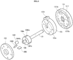
- a rotary compressor 100 may include a casing 110, a drive motor 120, and compression units 131, 132, and 133.
- the rotary compressor 100 may further include additional components.
- the casing 110 may form an exterior of the rotary compressor 100.
- the casing 110 may be formed in a cylindrical shape.
- the casing 110 may be divided into a vertical type casing or a horizontal type casing according to an installation mode of the rotary compressor 100.
- the vertical type casing may be a structure in which the drive motor 120 and the compression units 131, 132, 133, and 134 are disposed on upper and lower sides along an axial direction
- the horizontal type casing may be a structure in which the drive motor 120 and the compression units 131, 132, 133, and 134 are disposed on left and right or lateral sides.
- the drive motor 120, a rotational shaft 123, and the compression units 131, 132, 133, and 134 may be disposed inside of the casing 110.
- the casing 110 may include an upper shell 110a, an intermediate shell 110b, and a lower shell 110c.
- the upper shell 110a, the intermediate shell 110b, and the lower shell 110c may seal an inner space S
- the drive motor 120 may be disposed in the casing 110.
- the drive motor 120 may be fixed inside of the casing 110.
- the compression units 131, 132, 133, and 134 mechanically coupled by the rotational shaft 123 may be installed on or at one side of the drive motor 120.
- the drive motor 120 may provide power to compress a refrigerant.
- the drive motor 120 may include a stator 121, a rotor 122, and the rotational shaft 123.
- the stator 121 may be disposed in the casing 110.
- the stator 121 may be disposed inside of the casing 110.
- the stator 121 may be fixed inside of the casing 110.
- the stator 121 may be mounted on an inner peripheral surface of the cylindrical casing 110 by a method, such as shrink fit, for example.
- the stator 121 may be fixedly installed on an inner peripheral surface of the intermediate shell 110b.
- the rotor 122 may be spaced apart from the stator 121.
- the rotor 122 may be disposed inside of the stator 121.
- the rotational shaft 123 may be disposed on the rotor 122.
- the rotational shaft 122 may be disposed at a center of the rotor 122.
- the rotational shaft 123 may be, for example, press-fitted to the center of the rotor 122.
- the rotor 122 When power is applied to the stator 121, the rotor 122 may be rotated according to an electromagnetic interaction between the stator 121 and the rotor 122. Accordingly, the rotational shaft 123 coupled to the rotor 122 may rotate concentrically with the rotor 122.
- An oil flow path 125 may be formed at a center of the rotational shaft 123.
- the oil flow path 125 may extend in the axial direction.
- Oil through holes 126a and 126b may be formed in a middle of the oil flow path 125 toward an outer peripheral surface of the rotational shaft 123.
- the oil through holes 126a and 126b may include first oil through hole 126a belonging to a range of a first bearing portion 1311 and second oil through hole 126b belonging to a range of a second bearing portion 1321.
- One first oil through hole 126a and one second oil through hole 126b may be formed or a plurality of oil through holes 126a and a plurality of oil through holes 126b may be formed.
- An oil feeder 150 may be disposed in or at a lower end of the oil flow path 125.
- oil filling a lower portion of the casing 110 may be pumped by the oil feeder 150. Accordingly, the oil may be raised along the oil flow path 125, may be supplied to a sub bearing surface 1321a through the second oil through hole 126b, and may be supplied to a main bearing surface 1311a through the first oil through hole 126a.
- the first oil through hole 126a may be formed to overlap the first oil groove 1311b.
- the second oil through hole 126b may be formed to overlap the second oil groove 1321b. That is, oil supplied to the main bearing surface 1311a of main bearing 131 of compression units 131, 132, 133, and 134 and a sub bearing surface 1321a of sub bearing 132 of compression units 131, 132, 133, and 134 through the first oil through hole 126a and the second oil through hole 126b may be quickly introduced into a main-side second pocket 1313b and a sub-side second pocket 1323b.
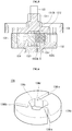
- the compression units 131, 132, 133, and 134 may comprise main bearing 131, sub bearing 132, cylinder 133 having a compression space 410 formed by the main bearing 131 and the sub bearing 132 installed on or at both sides in the axial direction, and rotor 134 disposed rotatably inside of the cylinder 133.
- the main bearing 131 and the sub bearing 132 may be disposed in the casing 110.
- the main bearing 131 and the sub bearing 132 may be fixed to the casing 110.
- the main bearing 131 and the sub bearing 132 may be spaced apart from each other along the rotational shaft 123.
- the main bearing 131 and the sub bearing 132 may be spaced apart from each other in the axial direction.
- the axial direction may refer to an up-down or vertical direction with respect to FIG. 1 .
- the main bearing 131 may be referred to as a "first bearing”
- the sub bearing 132 may be referred to as a "second bearing”.
- the main bearing 131 and the sub bearing 132 may support the rotational shaft 123 in a radial direction.
- the main bearing 131 and the sub bearing 132 may support the cylinder 133 and the rotor 134 in the axial direction.
- the main bearing 131 and the sub bearing 132 may include the first and second bearing portions 1311 and 1321 which support the rotational shaft 123 in the radial direction, and flange portions (flanges) 1312 and 1322 which extend in the radial direction from the bearing portions 1311 and 1321.
- the main bearing 131 may include the first bearing portion 1311 that supports the rotational shaft 123 in the radial direction and the first flange portion 1312 that extends in the radial direction from the first bearing portion 1311
- the sub bearing 132 may include the second bearing portion 1321 that supports the rotational shaft 123 in the radial direction and the second flange portion 1322 that extends in the radial direction from the second bearing portion 1321.
- Each of the first bearing portion 1311 and the second bearing portion 1321 may be formed in a bush shape.
- Each of the first flange portion 1312 and the second flange portion 1322 may be formed in a disk shape.
- the first oil groove 1311b may be formed on the main bearing surface 1311a which is a radially inner peripheral surface of the first bearing portion 1311.
- the second oil groove 1321b may be formed on the sub bearing surface 1321a which is a radially inner peripheral surface of the second bearing portion 1321.
- the first oil groove 1311b may be formed in a straight line or an oblique line between upper and lower ends of the first bearing portion 1311.
- the second oil groove 1321b may be formed in a straight line or an oblique line between upper and lower ends of the second bearing portion 1321.
- a first communication channel 1315 may be formed in the first oil groove 1311b.
- a second communication channel 1325 may be formed in the second oil groove 1321b.
- the first communication channel 1315 and the second communication channel 1325 may guide oil flowing into the main bearing surface 1311a and the sub bearing surface 1321a to a main-side back pressure pocket 1313 and a sub-side back pressure pocket 1323.
- the main-side back pressure pocket 1313 may be formed in the first flange portion 1312.
- the sub-side back pressure pocket 1323 may be formed in the second flange portion 1322.
- the main-side back pressure pocket 1313 may include a main-side first pocket 1313a and the main-side second pocket 1313b.
- the sub-side back pressure pocket 1323 may include a sub-side first pocket 1323a and the sub-side second pocket 1323b.
- first pockets 1313a and 1323a may include main-side first pocket 1313a and sub-side first pocket 1323a
- second pockets 1313b and 1323b may include main-side second pocket 1313b and sub-side second pocket 1323b.
- the main-side first pocket 1313a and the main-side second pocket 1313b may be formed at predetermined intervals along a circumferential direction.
- the sub-side first pocket 1323a and the sub-side second pocket 1323b may be formed at predetermined intervals along the circumferential direction.
- the main-side first pocket 1313a may form a lower pressure than the main-side second pocket 1313b, for example, an intermediate pressure between a suction pressure and a discharge pressure.
- the sub-side first pocket 1323a may form a lower pressure than the sub-side second pocket 1323b, for example, the intermediate pressure between the suction pressure and the discharge pressure.
- the pressure of the main-side first pocket 1313a and the pressure of the sub-side first pocket 1323a may correspond to each other.
- the pressure in the first main pocket 1313a may be reduced and form the intermediate pressure.
- the pressure of the sub-side first pocket 1323a may be reduced and form the intermediate pressure.
- Oil flowing into the main bearing surface 1311a through the first oil through hole 126a may flow into the main-side second pocket 1313b through the first communication flow channel 1315, and thus, the pressure of the main-side second pocket 1313b may be maintained at the discharge pressure or similar to the discharge pressure.
- Oil flowing into the sub bearing surface 1321a through the second oil through hole 126b may flow into the sub-side second pocket 1323b through the second communication channel 1325, and thus, the pressure of the second sub-side pocket 1323b may be maintained at the discharge pressure or similar to the discharge pressure.
- the inner peripheral surface of the cylinder 133 may be formed in a symmetrical ellipse shape having a pair of long and short axes, or an asymmetrical ellipse shape having several pairs of long and short axes.
- the inner peripheral surface of the cylinder 133 forming the compression space 410 may be formed in a circular shape.
- the cylinder 133 may be fastened to the main bearing 131 or the sub bearing 132 fixed to the casing 110 with a bolt.
- An empty space portion may be formed at a center of the cylinder 133 to form the compression space 410 including an inner peripheral surface.
- the empty space may be sealed by the main bearing 131 and the sub bearing 132 to form the compression space 410.
- the rotor 134 having an outer peripheral surface formed in a circular shape may be rotatably disposed in the compression space 410.
- a suction port 1331 and a discharge port 1332 may be respectively formed on an inner peripheral surface 133a of the cylinder 133 on both sides in the circumferential direction about a contact point P at which the inner peripheral surface 133a of the cylinder 133 and an outer peripheral surface 134c of the rotor 134 are in close substantial contact with each other.
- the suction port 1331 and the discharge port 1332 may be spaced apart from each other. That is, the suction port 1331 may be formed on an upstream side based on a compression path (rotational direction), and the discharge port 1332 may be formed on a downstream side in a direction in which the refrigerant is compressed.
- the suction port 1331 may be directly coupled to a suction pipe 113 that passes through the casing 110.
- the discharge port 1332 may be indirectly coupled with a discharge pipe 114 that communicates with the internal space S of the casing 110 and is coupled to pass through the casing 110. Accordingly, refrigerant may be directly suctioned into the compression space 410 through the suction port 1331, and the compressed refrigerant may be discharged to the internal space S of the casing 110 through the discharge port 1332 and then discharged to the discharge pipe 114. Therefore, the internal space S of the casing 110 may be maintained in a high-pressure state forming the discharge pressure.
- a high-pressure refrigerant discharged from the discharge port 1332 may stay in the internal space S adjacent to the compression units 131, 132, 133 and 134.
- the main bearing 131 is fixed to the inner peripheral surface of the casing 110, upper and lower sides of the internal space S of the casing 110 may be bordered or enclosed.
- the high-pressure refrigerant staying in the internal space S may flow through a discharge channel 1316 and be discharged to the outside through the discharge pipe 114 provided on or at the upper side of the casing 110.
- the discharge channel 1316 may penetrate the first flange portion 1312 of the main bearing 131 in the axial direction.
- the discharge channel 1316 may secure a sufficient channel area so that no channel resistance occurs. More specifically, the discharge channel 1316 may extend along the circumferential direction in a region which does not overlap with the cylinder 133 in the axial direction. That is, the discharge channel 1316 may be formed in an arc shape.
- the discharge channel 1316 may include a plurality of holes spaced apart in the circumferential direction. As described above, as the maximum channel area is secured, channel resistance may be reduced when the high-pressure refrigerant moves to the discharge pipe 114 provided on the upper side of the casing 110.
- a discharge valve 1335 to open and close the discharge port 1332 may be disposed in the discharge port 1332.
- the discharge valve 1335 may include a reed valve having one (first) end fixed and the other (second) end forming a free end.
- the discharge valve 1335 may be variously changed as needed, and may be, for example, a piston valve.
- a discharge groove (not illustrated) may be formed on the outer peripheral surface of the cylinder 133 so that the discharge valve 1335 may be mounted therein. Accordingly, a length of the discharge port 1332 may be reduced to a minimum, and thus, dead volume may be reduced. At least portion of the valve groove may be formed in a triangular shape to secure a flat valve seat surface, as illustrated in FIG. 2 .
- one discharge port 1332 is provided as an example; however, embodiments are not limited thereto, and a plurality of discharge ports 1332 may be provided along a compression path (compression progress direction).
- the rotor 134 may be disposed on the cylinder 133.
- the rotor 134 may be disposed inside of the cylinder 133.
- the rotor 134 may be disposed in the compression space 410 of the cylinder 133.
- the outer peripheral surface 134c of the rotor 134 may be formed in a circular shape.
- the rotational shaft 123 may be disposed at the center of the rotor 134.
- the rotational shaft 123 may be integrally coupled to the center of the rotor 134. Accordingly, the rotor 134 has a center O r which matches an axial center O s of the rotational shaft 123, and may rotate concentrically together with the rotational shaft 123 around the center O r of the rotor 134.
- the center O r of the rotor 134 may be eccentric with respect to a center O c of the cylinder 133, that is, the center O c of the internal space of the cylinder 133.
- One side of the outer peripheral surface 134c of the rotor 134 may almost come into contact with the inner peripheral surface 133a of the cylinder 133.
- the outer peripheral surface 134c of the rotor 134 does not actually come into contact with the inner peripheral surface 133a of the cylinder 133.
- the outer peripheral surface 134c of the rotor 134 and the inner peripheral surface of the cylinder 133 are spaced apart from each other so that frictional damage does not occur, but should be close to each other so as to limit leakage of high-pressure refrigerant in a discharge pressure region to a suction pressure region through between the outer peripheral surface 134c of the rotor 134 and the inner peripheral surface 133a of the cylinder 133.
- a point at which one side of the rotor 134 is almost in contact with the cylinder 133 may be regarded as the contact point P.
- the rotor 134 may have at least one vane slot 1341a, 1341b, and 1341c formed at an appropriate location of the outer peripheral surface 134c along the circumferential direction.
- the vane slots 1341a, 1341b, and 1341c may include first vane slot 1341a, second vane slot 1341b, and third vane slot 1341c.
- three vane slots 1341a, 1341b, and 1341c are described as an example.
- embodiments are not limited thereto and the vane slot may be variously changed according to a number of vanes 1351, 1352, and 1353.
- Each of the first to third vanes 1351, 1352, and 1353 may be slidably coupled to each of the first to third vane slots 1341a, 1341b, and 1341c.
- a straight line extending from the first to third vane slots 1341a, 1341b, and 1341c does not pass through the center Or of the rotor 134 as an example.
- Each of the first to third vane slots 1341a, 1341 b, and 1341c may be formed toward a radial direction with respect to the center O r of the rotor 134. That is, an extending straight line of each of the first to third vane slots 1341a, 1341b, and 1341c may pass through the center O r of the rotor 134, respectively.
- First to third back pressure chambers 1342a, 1342b, and 1342c may be respectively formed on inner ends of the first to third vane slots 1341a, 1341 b, and 1341c, so that the first to third vanes 1351, 1352, and 1353 allows oil or refrigerant to flow into a rear side and the first to third vanes 1351, 1352, and 1353 may be biased in a direction of the inner peripheral surface of the cylinder 133.
- the first to third back pressure chambers 1342a, 1342b, and 1342c may be sealed by the main bearing 131 and the sub bearing 132.
- the first to third back pressure chambers 1342a, 1342b, and 1342c may each independently communicate with the back pressure pockets 1313 and 1323. Alternatively, the first to third back pressure chambers 1342a, 1342b, and 1342c may communicate with each other by the back pressure pockets 1313 and 1323.
- the back pressure pockets 1313 and 1323 may be formed on the main bearing 131 and the sub bearing 132, respectively, as illustrated in FIG. 1 .
- the back pressure pockets 1313 and 1323 may be formed only on any one of the main bearing 131 or the sub bearing 132.
- the back pressure pockets 1313 and 1323 are formed in both the main bearing 131 and the sub bearing 132 as an example.
- the back pressure pockets 1313 and 1323 may include the main-side back pressure pocket 1313 formed in the main bearing 131 and the sub-side back pressure pocket 1323 formed in the sub bearing 132.
- the main-side back pressure pocket 1313 may include the main-side first pocket 1313a and the main-side second pocket 1313b.
- the main-side second pocket 1313b may generate a higher pressure than the main-side first pocket 1313a.
- the sub-side back pressure pocket 1323 may include the sub-side first pocket 1323a and the sub-side second pocket 1323b.
- the sub-side second pocket 1323b may generate a higher pressure than the sub-side first pocket 1323a.
- the main-side first pocket 1313a and the sub-side first pocket 1323a may communicate with a vane chamber to which a vane located at a relatively upstream side (from the suction stroke to the discharge stroke) among the vanes 1351, 1352, and 1353 belongs
- the main-side second pocket 1313b and the sub-side second pocket 1323b may communicate with a vane chamber to which a vane located at a relatively downstream side (from the discharge stroke to the suction stroke) among the vanes 1351, 1352, and 1353 belongs.
- first vane 1351 the vane closest to the contact point P based on a compression progress direction
- the second vane 1352 and the third vane 1353 the following vanes
- first vane 1351 and the second vane 1352, the second vane 1352 and the third vane 1353, and the third vane 1353 and the first vane 1351 may be spaced apart from each other by a same circumferential angle.
- first compression chamber V1 a compression chamber formed by the first vane 1351 and the second vane 1352
- second compression chamber V2 a compression chamber formed by the second vane 1352 and the third vane 1353
- third compression chamber V3 all of the compression chambers V1, V2, and V3 have a same volume at a same crank angle.
- the first compression chamber V1 may be referred to as a suction chamber
- the third compression chamber V3 may be referred to as a discharge chamber.
- Each of the first to third vanes 1351, 1352, and 1353 may be formed in a substantially rectangular parallelepiped shape. Referring to ends of each of the first to third vanes 1351, 1352, and 1353 in the longitudinal direction, a surface in contact with the inner peripheral surface 133a of the cylinder 133 may be referred to as a "distal end surface", and a surface facing each of the first to third back pressure chambers 1342a, 1342b, and 1342c may be referred to as a "rear end surface”.
- the distal end surface of each of the first to third vanes 1351, 1352, and 1353 may be formed in a curved shape so as to come into line contact with the inner peripheral surface 133a of the cylinder 133.
- the rear end surface of each of the first to third vanes 1351, 1352, and 1353 may be formed to be flat to be inserted into each of the first to third back pressure chambers 1342a, 1342b, and 1342c and to receive the back pressure evenly.
- each of the first to third vanes 1351, 1352, 1353 may be withdrawn from each of the first to third vane slots 1341 a, 1341 b, and 1341 c, due to centrifugal force generated by rotation of the rotor 134 and a back pressure of each of the first to third back pressure chambers 1342a, 1342b, and 1342c disposed at a rear side of each of the first to third back pressure chambers 1342a, 1342b, and 1342c. Accordingly, the distal end surface of each of the first to third vanes 1351, 1352, and 1353 comes into contact with the inner peripheral surface 133a of the cylinder 133.
- the distal end surface of each of the first to third vanes 1351, 1352, and 1353 is in contact with the inner peripheral surface 133a of the cylinder 133 may mean that the distal end surface of each of the first to third vanes 1351, 1352, and 1353 comes into direct contact with the inner peripheral surface 133a of the cylinder 133, or the distal end surface of each of the first to third vanes 1351, 1352, and 1353 is adjacent enough to come into direct contact with the inner peripheral surface 133a of the cylinder 133.
- the compression space 410 of the cylinder 133 forms a compression chamber (including suction chamber or discharge chamber) (V1, V2, V3) by the first to third vanes 1351, 1352, and 1353, and a volume of each of the compression chambers V1, V2, V3 may be changed by eccentricity of the rotor 134 while moving according to rotation of the rotor 134. Accordingly, while the refrigerant filling each of the compression chambers V1, V2, and V3 moves along the rotor 134 and the vanes 1351, 1352, and 1353, the refrigerant is suctioned, compressed, and discharged.
- V1, V2, V3 suction chamber or discharge chamber
- vanes 1351, 1352, and 1353 there are three vanes 1351, 1352, and 1353, three vane slots 1341a, 1341b, and 1341c, and three back pressure chambers 1342a, 1342b, and 1342c.
- the number of the vanes 1351, 1352, and 1353, the number of vane slots 1341a, 1341b, and 1341c, and the number of back pressure chambers 1342a, 1342b, and 1342c may be variously changed.
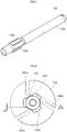
- the rotational shaft 123 may include a main body 123a, a coupling portion 123b, and a protrusion 123c.
- the rotational shaft 123 may be formed of a material different from that of the rotor 134.
- the rotational shaft 123 may be formed of a metal material, and the rotor 134 may be formed of an aluminum material. Accordingly, it is possible to reduce noise generated by the rotary compressor 100 and reduce manufacturing costs.
- the main body 123a may extend in the axial direction.
- a cross section of the main body 123a may be formed in a circular shape.
- the main body 123a may pass through the main bearing 131, the rotor 134, and the sub bearing 132.
- the coupling portion 123b may be formed on the main body 123a.
- the coupling portion 123b may be formed in or at a lower region of the main body 123a.
- the coupling portion 123b may be disposed in the rotor 134.
- the coupling portion 123b may face an inner peripheral surface 134d of the rotor 134.
- the coupling portion 123b may contact the inner peripheral surface 134d of the rotor 134.
- the coupling portion 123b may face a groove 134e of the rotor 134.
- the protrusion 123c may be disposed on the main body 123a.
- the protrusion 123c may be disposed in a lower region of the main body 123a.
- the protrusion 123c may protrude outward from an outer peripheral surface of the main body 123a.
- the protrusion 123c may be disposed on the coupling portion 123b.
- the protrusion 123c may protrude outward from the outer peripheral surface of the coupling portion 123b.
- the protrusion 123c may face the groove 134e of the rotor 134.
- the protrusion 123c may be disposed in the groove 134e of the rotor 134.
- the protrusion 123c may be spaced apart from the groove 134e of the rotor 134 by predetermined distances d2 and d3. This gap between the protrusion 123c and the groove 134e allows the rotation shaft 123 to be vertically movable relative to the rotor 134 while the coupling between the groove 134e and the protrusion 123c is maintained. Further, due to this structure, it is possible to reduce a load applied to the rotor 134 and the rotational shaft 123 when the rotor 134 rotates.
- An outer surface of the protrusion 123c may be formed in a curved shape.
- the protrusion 123c may not overlap the vanes 1351, 1352, and 1353 in the radial direction. Accordingly, space efficiency may be improved.
- An axial length d4 of the protrusion 123c may be less than or equal to an axial length d5 of the groove 134e of the rotor 134. Accordingly, when the rotational shaft 123 may move up and down with respect to the rotor 134, friction caused by contact between the rotor 134 and the lower surface of the main bearing 131 and/or the upper surface of the sub bearing 132 may be reduced, and thus, it is possible to prevent damage to a product and improve compression efficiency.
- the axial length d4 of the protrusion 123c may be 0.65 times to 1 time the axial length d5 of the groove 134e of the rotor 134.
- the axial length d4 of the protrusion 123c is 0.65 times or less than 0.65 times the axial length d5 of the groove 134e of the rotor 134, an axial movement of the rotor 134 increases when the rotor 134 rotates, and thus, reliability may decrease.
- a difference between the axial length d5 of the groove 134e of the rotor 134 the axial length d4 of the protrusion 123c may be less than 1 mm.
- the difference between the axial length d4 of the protrusion 123c and the axial length d5 of the groove 134e of the rotor 134 is 1 mm or more than 1 mm, the axial movement of the rotor 134 increases when the rotor 134 rotates, and thus, reliability may decrease.
- the distances d2 and d3 between the outer surface of the protrusion 123c and the inner surface of the groove 134e of the rotor 134 may be shorter than the distance d1 between the outer peripheral surface 134c of the rotor 134 and the inner peripheral surface 133a of the cylinder 133, for example, a minimum distance.
- a lower surface 123d of the protrusion 123c may be in contact with an upper surface 1323c of the second bearing 132.
- the lower surface 123d of the protrusion 123c may be in surface contact with the upper surface 1323c of the second bearing 132.
- the upper surface 1323c of the second bearing 132 in contact with the lower surface 123d of the protrusion 123c may be disposed between the sub-side first pocket 1323a and the sub-side second pocket 1323b.
- the lower surface 123d of the protrusion 123c may be ground.
- each of the lower surface 123d of the protrusion 123c and the upper surface 1323c of the second bearing 132 may be referred to as a "thrust surface".
- the protrusion 123c may include a plurality of protrusions.
- the plurality of protrusions of the rotor 134 may correspond to the number of the plurality of grooves.
- the plurality of protrusions may be spaced apart from each other. Separation distances between the plurality of protrusions may be the same. Separation angles of the plurality of protrusions based on a center of the rotational shaft 123 may correspond to each other.
- the number of protrusions may correspond to the number of vanes 1351, 1352, and 1353.
- the plurality of protrusions may not overlap the vanes 1351, 1352, and 1353 in the radial direction.
- the groove 134e may be formed on the inner peripheral surface 134d of the rotor 134.
- the groove 134e of the rotor 134 may be recessed inwardly from the inner peripheral surface 134d of the rotor 134.
- the groove 134e of the rotor 134 may face the protrusion 123c.
- the protrusion 123c may be disposed in the groove 134e of the rotor 134.
- the inner surface of the groove 134e of the rotor 134 may be spaced apart from the outer surface of the protrusion 123c by the predetermined distances d2 and d3.
- the inner surface of the groove 134e of the rotor 134 facing the outer surface of the protrusion 123c may be formed in a curved shape.
- the grooves 134e of the rotor 134 may not overlap the vanes 1351, 1352, and 1353 in the radial direction.
- the groove 134e of the rotor 134 may include a plurality of grooves.
- the plurality of grooves of the rotor 134 may be spaced apart from each other. Separation distances of the plurality of grooves of the rotor 134 may correspond to each other. Angles formed by the plurality of grooves of the rotor 134 based on the center Or of the rotor 134 may correspond to each other.
- the number of the plurality of grooves of the rotor 134 may correspond to the number of the plurality of protrusions.
- the number of grooves of the rotor 134 may correspond to the number of vanes 1351, 1352, and 1353.
- the plurality of grooves of the rotor 134 may not overlap the vanes 1351, 1352, and 1353 in the radial direction.
- each of the first pockets 1313a and 1323a may be formed in an asymmetrical shape.
- An outer diameter of each of the first pockets 1313a and 1323a may decrease toward the discharge port 1332.
- Each of the second pockets 1313b and 1323b may be formed in an asymmetrical shape, and an outer diameter of each of the second pockets 1313b and 1323b may decrease toward the discharge port 1332. Accordingly, behavior of each of the vanes 1351, 1352, and 1353 may be stabilized, refrigerant prevented from leaking into the space between the distal end surface of each of the vanes 1351, 1352, and 1353 and the inner peripheral surface of the cylinder 133, and thus, compression efficiency may be improved.
- each of the first pockets 1313a and 1323a and each of the second pockets 1313b and 1323b may have different pressures. More specifically, a pressure in each of the second pockets 1313b and 1323b may be higher than a pressure in each of the first pockets 1313a and 1323a. Accordingly, it is possible to decrease a size of a product.
- the second pockets 1313b and 1323b may be disposed closer to the rotational shaft 123 than the first pockets 1313a and 1323a.
- the second pockets 1313b and 1323b may communicate with the through holes 1317 and 1327.
- the through hole 1317 and 1327 may include first through hole 1317 through which the rotational shaft 123 passes in the main bearing 131, and second through hole 1327 through which the rotational shaft 123 passes in the sub bearing 132. Accordingly, compression efficiency of the rotary compressor 100 may be improved.
- the volume of the first compression chamber V1 is continuously increases until the first vane 1351 passes through the suction port 1331 and the second vane 1352 reaches a completion point of suction w.
- the refrigerant may continuously flow into the first compression chamber V1 from the suction port 1331.
- the first compression chamber V1 may be sealed and may move in a direction of the discharge port 1332 together with the rotor 134. In this process, the volume of a first compression chamber V1 continuously decreases, and refrigerant in the first compression chamber V1 may be gradually compressed.
- the discharge valve 1335 may be opened by the pressure of the first compression chamber V1 while the first compression chamber V1 communicates with the discharge port 1332.
- the refrigerant in the first compression chamber V1 may be discharged to the internal space of the casing 110 through the discharge port 1332.
- the intermediate pressure between the suction pressure and the discharge pressure may be formed in the main-side first pocket 1313a, and the discharge pressure (actually, a pressure slightly lower than the discharge pressure) may be formed in the main-side second pocket 1313b. Accordingly, the intermediate pressure lower than the discharge pressure is formed in the main-side first pocket 1313a, and thus, mechanical efficiency between the cylinder 133 and the vanes 1351, 1352, and 1353 may increase.
- the discharge pressure or the pressure slightly lower than the discharge pressure is formed in the main second pocket 1313b, and thus, the vanes 1351, 1352, and 1353 are disposed adjacent to the cylinder 133 to increase the mechanical efficiency while suppressing leakage between the compression chambers and increasing efficiency.
- the protrusion 123c is formed on the outer peripheral surface of the rotational shaft 123 and the groove 134e is formed on the inner peripheral surface 134d of the rotor 134 as an example.
- the protrusion 123c may be formed on the inner peripheral surface 134d of the rotor 134 and the groove 134e may be formed on the outer peripheral surface of the rotational shaft 123.
- the protrusion 123c and the groove 134e may face each other.
- the protrusion 123c may be disposed in the groove 134e, and the outer surface of the protrusion 123c may be spaced apart from the inner surface of the groove 134e by the predetermined distances d2 and d3.
- the difference between the axial length of the groove 134e and the axial length of the protrusion 123c may be less than 1 mm.
- the outer surface of the protrusion 123c may be formed in a curved shape, and the inner surface of the groove 134e facing the outer surface of the protrusion 123c may be formed in a curved shape.
- the protrusion 123c may include a plurality of protrusions spaced apart from each other, and the groove 134e may include a plurality of grooves spaced apart from each other.
- the separation distances between the plurality of protrusions may correspond to each other, and the separation distances between the plurality of grooves may correspond to each other.
- the number of vanes 1351, 1352, and 1353 may correspond to the number of the plurality of protrusions and/or the number of the plurality of grooves.
- a configuration A described in a specific embodiment and/or a drawing may be coupled to a configuration B described in another embodiment and/or a drawing. That is, even if a combination between components is not directly described, it means that the combination is possible except for a case where it is described that the combination is impossible.
- a rotary compressor capable of reducing friction of a main bearing of a rotor to prevent damage to a product and improve compression efficiency. Moreover, according to embodiments disclosed herein, it is possible to provide a rotary compressor capable of handling load caused by rotation of the rotor.
- Embodiments disclosed herein provide a rotary compressor capable of reducing friction of a main bearing of a rotor to prevent damage to a product and improve compression efficiency. Embodiments disclosed herein also provide a rotary compressor capable of handling a load caused by a rotation of the rotor.
- Embodiments disclosed herein provide a rotary compressor that may include a rotational shaft including a protrusion formed on an outer peripheral surface; first and second bearings configured to support the rotational shaft in a radial direction; a cylinder disposed between the first and second bearings to form a compression space; a rotor disposed in the compression space and coupled to the rotational shaft to compress a refrigerant as the rotor rotates; and at least one vane slidably inserted into the rotor, the at least one vane coming into contact with an inner peripheral surface of the cylinder to separate the compression space into a plurality of regions.
- the rotor may include a groove which is formed on an inner peripheral surface and faces the protrusion. Accordingly, it is possible to reduce friction of a main bearing of a rotor to prevent damage to a product and improve compression efficiency. Moreover, it is possible to handle a load caused by rotation of the rotor.
- the rotational shaft and the rotor may be formed of different materials.
- An axial length of the protrusion may be shorter than an axial length of the groove.
- the axial length of the protrusion may be 0.6 times to 1 time the axial length of the groove.
- a difference between the axial length of the groove and the axial length of the protrusion may be 1 mm or more.
- the protrusion may include a plurality of protrusions spaced apart from each other, and the groove may include a plurality of grooves spaced apart from each other. Separation distances between the plurality of protrusions may correspond each other. A number of the at least one vane may correspond to a number of the plurality of protrusions.
- a distance between an outer surface of the protrusion and an inner surface of the groove may be shorter than a distance between an outer peripheral surface of the rotor and the inner peripheral surface of the cylinder.
- the protrusion may not overlap the at least one vane in the radial direction.
- An outer surface of the protrusion may be formed in a curved shape.
- a lower surface of the protrusion may be in surface contact with an upper surface of the second bearing.
- the upper surface of the second bearing may include first and second pockets.
- the lower surface of the protrusion may be in surface contact with a space between the first and second pockets of the upper surface of the second bearing.
- Embodiments disclosed herein provide a rotary compressor that may include a rotational shaft including a groove formed on an outer peripheral surface; first and second bearings configured to support the rotational shaft in a radial direction; a cylinder disposed between the first and second bearings to form a compression space; a rotor disposed in the compression space and coupled to the rotational shaft to compress a refrigerant as the rotor rotates; and at least one vane slidably inserted into the rotor, the at least one vane coming into contact with an inner peripheral surface of the cylinder to separate the compression space into a plurality of regions.
- the rotor may include a protrusion which is formed on an inner peripheral surface and faces the groove. Accordingly, it is possible to reduce friction of a main bearing of a rotor to prevent damage to a product and improve compression efficiency. Moreover, it is possible to handle a load caused by rotation of the rotor.
- the rotational shaft and the rotor may be formed of different materials.
- a difference between an axial length of the groove between an axial length of the protrusion may be 1 mm or more.
- the protrusion may include a plurality of protrusions spaced apart from each other, and the groove may include a plurality of grooves spaced apart from each other. Separation distances between the plurality of protrusions may correspond each other.
- a number of the at least one vane may correspond to a number of the plurality of protrusions.
- An outer surface of the protrusion may be formed in a curved shape.
- first, second, third, etc. may be used herein to describe various elements, components, regions, layers and/or sections, these elements, components, regions, layers and/or sections should not be limited by these terms. These terms are only used to distinguish one element, component, region, layer or section from another region, layer or section. Thus, a first element, component, region, layer or section could be termed a second element, component, region, layer or section without departing from the teachings.
- spatially relative terms such as “lower”, “upper” and the like, may be used herein for ease of description to describe the relationship of one element or feature to another element(s) or feature(s) as illustrated in the figures. It will be understood that the spatially relative terms are intended to encompass different orientations of the device in use or operation, in addition to the orientation depicted in the figures. For example, if the device in the figures is turned over, elements described as “lower” relative to other elements or features would then be oriented “upper” relative to the other elements or features. Thus, the exemplary term “lower” can encompass both an orientation of above and below. The device may be otherwise oriented (rotated 90 degrees or at other orientations) and the spatially relative descriptors used herein interpreted accordingly.
- Embodiments are described herein with reference to cross-section illustrations that are schematic illustrations of idealized embodiments (and intermediate structures). As such, variations from the shapes of the illustrations as a result, for example, of manufacturing techniques and/or tolerances, are to be expected. Thus, embodiments should not be construed as limited to the particular shapes of regions illustrated herein but are to include deviations in shapes that result, for example, from manufacturing.
- any reference in this specification to "one embodiment,” “an embodiment,” “example embodiment,” etc. means that a particular feature, structure, or characteristic described in connection with the embodiment is included in at least one embodiment.
- the appearances of such phrases in various places in the specification are not necessarily all referring to the same embodiment.
Abstract
Description
- A rotary compressor is disclosed herein.
- In general, a compressor refers to a device configured to receive power from a power generating device, such as a motor or a turbine, and compress a working fluid, such as air or a refrigerant. More specifically, the compressor is widely applied to the entire industry of home appliances, in particular, a vapor compression type refrigeration cycle (hereinafter referred to as a "refrigeration cycle").
- Compressors may be classified into a reciprocating compressor, a rotary compressor, or a scroll compressor according to a method of compressing the refrigerant. A compression method of the rotary compressor may be classified into a method in which a vane is slidably inserted into a cylinder to come into contact with a rotor, and a method in which a vane is slidably inserted into a rotor to come into contact with a cylinder. In general, the former is referred to as a rotary compressor and the latter is referred to as a vane rotary compressor.
- In the rotary compressor, the vane inserted into the cylinder is drawn out toward the rotor by an elastic force or a back pressure, and comes into contact with an outer peripheral surface of the rotor. In the vane rotary compressor, the vane inserted into the rotor rotates with the rotor and is drawn out by a centrifugal force and a back pressure, and comes into contact with an inner peripheral surface of the cylinder.
- In the rotary compressor, compression chambers as many as a number of vanes per rotation of the rotor are independently formed, and the respective compression chambers perform suction, compression, and discharge strokes at the same time. In the vane rotary compressor, compression chambers as many as a number of vanes per rotation of the rotor are continuously formed, and the respective compression chambers sequentially perform suction, compression, and discharge strokes.
- In the vane rotary compressor, in general, a plurality of vanes rotates together with the rotor and slide in a state in which a distal end surface of the vane is in contact with the inner peripheral surface of the cylinder, and thus, friction loss increases compared to a general rotary compressor. In addition, in the vane rotary compressor, the inner peripheral surface of the cylinder is formed in a circular shape. However, recently, a vane rotary compressor (hereinafter, referred to as a "hybrid rotary compressor") has been introduced, which has a so-called hybrid cylinder an inner peripheral surface of which is formed in an ellipse or a combination of an ellipse and a circle, and thus, friction loss is reduced and compression efficiency improved.
- In the hybrid rotary compressor, the inner peripheral surface of the cylinder is formed in an asymmetrical shape. Accordingly, a location of a contact point which separates a region where a refrigerant flows in and a compression strokes starts and a region where a discharge stroke of a compressed refrigerant is performed has a great influence on efficiency of the compressor.
- In particular, in a structure in which a suction port and a discharge port are sequentially formed adjacent to each other in a direction opposite to a rotational direction of the rotor in order to achieve a high compression ratio by increasing a compression path as much as possible, the position of the contact point greatly affects the efficiency of the compressor.
- However, when the rotational shaft is pressed into a rotor and formed integrally with the rotor, the rotor also moves up and down according to an up-down or vertical movement of the rotational shaft, a product is damaged by friction between the rotor and a thrust surface of a main bearing, and thus, compression efficiency decreases. In addition, when the rotational shaft is press-fitted to an inner peripheral surface of a serration-processed rotor, there is a problem that a load caused by rotation of the rotor cannot be handled.
- Embodiments will be described in detail with reference to the following drawings in which like reference numerals refer to like elements, and wherein:
-
FIG. 1 is a vertical cross-sectional view of a rotary compressor according to an embodiment; -
FIG. 2 is a transverse cross-sectional view of the rotary compressor according to an embodiment; -
FIGS. 3 and4 are exploded perspective views of a partial configuration of the rotary compressor according to an embodiment; -
FIG. 5 is a cross-sectional view, taken along line V-V' ofFIG. 2 ; -
FIG. 6 is a perspective view of a rotor according to an embodiment; -
FIG. 7 is a perspective view of a rotational shaft according to an embodiment; -
FIG. 8 is a plan view of the rotor and the rotational shaft according to an embodiment; -
FIG. 9 is a side view of the rotor and the rotational shaft according to an embodiment; -
FIG. 10 is a perspective view of the rotational shaft according to an embodiment; -
FIG. 11 is a perspective view of a partial configuration of the rotary compressor according to an embodiment; and -
FIGS. 12 to 14 are operational diagrams of the rotary compressor according to an embodiment. - Hereinafter, embodiments will be described with reference to the accompanying drawings. Wherever possible, the same or similar components have been assigned the same or similar reference numerals, and repetitive description has been omitted.
- In describing embodiments, when a component is referred to as being "coupled" or "connected" to another component, it should be understood that the component may be directly coupled to or connected to another component, both different components may exist therebetween.
- In addition, in describing embodiments, if it is determined that description of related known technologies may obscure the gist of embodiments, the description will be omitted. In addition, the accompanying drawings are for easy understanding of the embodiments, and a technical idea disclosed is not limited by the accompanying drawings, and it is to be understood as including all changes, equivalents, or substitutes falling within the spirit and scope.
- Meanwhile, terms of the specification can be replaced with terms such as document, specification, description.
-
FIG. 1 is a vertical cross-sectional view of a rotary compressor according to an embodiment.FIG. 2 is a transverse cross-sectional view of the rotary compressor according to an embodiment.FIGS. 3 and4 are exploded perspective views of a partial configuration of the rotary compressor according to an embodiment.FIG. 5 is a cross-sectional view, taken along line V-V' ofFIG. 2 .FIG. 6 is a perspective view of a rotor according to an embodiment.FIG. 7 is a perspective view of a rotational shaft according to an embodiment.FIG. 8 is a plan view of the rotor and the rotational shaft according to an embodiment.FIG. 9 is a side view of the rotor and the rotational shaft according to an embodiment.FIG. 10 is a perspective view of the rotational shaft according to an embodiment.FIG. 11 is a perspective view of a partial configuration of the rotary compressor according to an embodiment.FIGS. 12 to 14 are operational diagrams of the rotary compressor according to an embodiment. - Referring to
FIGS. 1 to 14 , arotary compressor 100 according to an embodiment may include acasing 110, adrive motor 120, andcompression units rotary compressor 100 may further include additional components. - The
casing 110 may form an exterior of therotary compressor 100. Thecasing 110 may be formed in a cylindrical shape. Thecasing 110 may be divided into a vertical type casing or a horizontal type casing according to an installation mode of therotary compressor 100. The vertical type casing may be a structure in which thedrive motor 120 and thecompression units drive motor 120 and thecompression units drive motor 120, arotational shaft 123, and thecompression units casing 110. Thecasing 110 may include anupper shell 110a, anintermediate shell 110b, and alower shell 110c. Theupper shell 110a, theintermediate shell 110b, and thelower shell 110c may seal an inner space S. - The
drive motor 120 may be disposed in thecasing 110. Thedrive motor 120 may be fixed inside of thecasing 110. Thecompression units rotational shaft 123 may be installed on or at one side of thedrive motor 120. - The
drive motor 120 may provide power to compress a refrigerant. Thedrive motor 120 may include astator 121, arotor 122, and therotational shaft 123. - The
stator 121 may be disposed in thecasing 110. Thestator 121 may be disposed inside of thecasing 110. Thestator 121 may be fixed inside of thecasing 110. Thestator 121 may be mounted on an inner peripheral surface of thecylindrical casing 110 by a method, such as shrink fit, for example. For example, thestator 121 may be fixedly installed on an inner peripheral surface of theintermediate shell 110b. - The
rotor 122 may be spaced apart from thestator 121. Therotor 122 may be disposed inside of thestator 121. Therotational shaft 123 may be disposed on therotor 122. Therotational shaft 122 may be disposed at a center of therotor 122. Therotational shaft 123 may be, for example, press-fitted to the center of therotor 122. - When power is applied to the
stator 121, therotor 122 may be rotated according to an electromagnetic interaction between thestator 121 and therotor 122. Accordingly, therotational shaft 123 coupled to therotor 122 may rotate concentrically with therotor 122. - An
oil flow path 125 may be formed at a center of therotational shaft 123. Theoil flow path 125 may extend in the axial direction. Oil throughholes oil flow path 125 toward an outer peripheral surface of therotational shaft 123. - The oil through
holes hole 126a belonging to a range of afirst bearing portion 1311 and second oil throughhole 126b belonging to a range of asecond bearing portion 1321. One first oil throughhole 126a and one second oil throughhole 126b may be formed or a plurality of oil throughholes 126a and a plurality of oil throughholes 126b may be formed. - An
oil feeder 150 may be disposed in or at a lower end of theoil flow path 125. When therotational shaft 123 rotates, oil filling a lower portion of thecasing 110 may be pumped by theoil feeder 150. Accordingly, the oil may be raised along theoil flow path 125, may be supplied to asub bearing surface 1321a through the second oil throughhole 126b, and may be supplied to amain bearing surface 1311a through the first oil throughhole 126a. - The first oil through
hole 126a may be formed to overlap thefirst oil groove 1311b. The second oil throughhole 126b may be formed to overlap thesecond oil groove 1321b. That is, oil supplied to themain bearing surface 1311a ofmain bearing 131 ofcompression units sub bearing surface 1321a of sub bearing 132 ofcompression units hole 126a and the second oil throughhole 126b may be quickly introduced into a main-sidesecond pocket 1313b and a sub-sidesecond pocket 1323b. - The
compression units main bearing 131, sub bearing 132,cylinder 133 having acompression space 410 formed by themain bearing 131 and the sub bearing 132 installed on or at both sides in the axial direction, androtor 134 disposed rotatably inside of thecylinder 133. ReferringFIGS. 1 and2 , themain bearing 131 and thesub bearing 132 may be disposed in thecasing 110. Themain bearing 131 and thesub bearing 132 may be fixed to thecasing 110. Themain bearing 131 and thesub bearing 132 may be spaced apart from each other along therotational shaft 123. Themain bearing 131 and thesub bearing 132 may be spaced apart from each other in the axial direction. In this embodiment, the axial direction may refer to an up-down or vertical direction with respect toFIG. 1 . Moreover, in this embodiment, themain bearing 131 may be referred to as a "first bearing", and thesub bearing 132 may be referred to as a "second bearing". - The
main bearing 131 and thesub bearing 132 may support therotational shaft 123 in a radial direction. Themain bearing 131 and thesub bearing 132 may support thecylinder 133 and therotor 134 in the axial direction. Themain bearing 131 and thesub bearing 132 may include the first andsecond bearing portions rotational shaft 123 in the radial direction, and flange portions (flanges) 1312 and 1322 which extend in the radial direction from the bearingportions main bearing 131 may include thefirst bearing portion 1311 that supports therotational shaft 123 in the radial direction and thefirst flange portion 1312 that extends in the radial direction from thefirst bearing portion 1311, and thesub bearing 132 may include thesecond bearing portion 1321 that supports therotational shaft 123 in the radial direction and thesecond flange portion 1322 that extends in the radial direction from thesecond bearing portion 1321. - Each of the
first bearing portion 1311 and thesecond bearing portion 1321 may be formed in a bush shape. Each of thefirst flange portion 1312 and thesecond flange portion 1322 may be formed in a disk shape. Thefirst oil groove 1311b may be formed on themain bearing surface 1311a which is a radially inner peripheral surface of thefirst bearing portion 1311. Thesecond oil groove 1321b may be formed on thesub bearing surface 1321a which is a radially inner peripheral surface of thesecond bearing portion 1321. Thefirst oil groove 1311b may be formed in a straight line or an oblique line between upper and lower ends of thefirst bearing portion 1311. Thesecond oil groove 1321b may be formed in a straight line or an oblique line between upper and lower ends of thesecond bearing portion 1321. - A
first communication channel 1315 may be formed in thefirst oil groove 1311b. Asecond communication channel 1325 may be formed in thesecond oil groove 1321b. Thefirst communication channel 1315 and thesecond communication channel 1325 may guide oil flowing into themain bearing surface 1311a and thesub bearing surface 1321a to a main-side backpressure pocket 1313 and a sub-sideback pressure pocket 1323. - The main-side back
pressure pocket 1313 may be formed in thefirst flange portion 1312. The sub-side backpressure pocket 1323 may be formed in thesecond flange portion 1322. The main-side backpressure pocket 1313 may include a main-sidefirst pocket 1313a and the main-sidesecond pocket 1313b. The sub-side backpressure pocket 1323 may include a sub-sidefirst pocket 1323a and the sub-sidesecond pocket 1323b. In this embodiment,first pockets first pocket 1313a and sub-sidefirst pocket 1323a, andsecond pockets second pocket 1313b and sub-sidesecond pocket 1323b. - The main-side
first pocket 1313a and the main-sidesecond pocket 1313b may be formed at predetermined intervals along a circumferential direction. The sub-sidefirst pocket 1323a and the sub-sidesecond pocket 1323b may be formed at predetermined intervals along the circumferential direction. - The main-side
first pocket 1313a may form a lower pressure than the main-sidesecond pocket 1313b, for example, an intermediate pressure between a suction pressure and a discharge pressure. The sub-sidefirst pocket 1323a may form a lower pressure than the sub-sidesecond pocket 1323b, for example, the intermediate pressure between the suction pressure and the discharge pressure. The pressure of the main-sidefirst pocket 1313a and the pressure of the sub-sidefirst pocket 1323a may correspond to each other. - As oil passes through a fine passage between a main-side first bearing
protrusion 1314a and anupper surface 134a of therotor 134 and flows into the main-sidefirst pocket 1313a, the pressure in the firstmain pocket 1313a may be reduced and form the intermediate pressure. As oil passes through a fine passage between a sub-sidefirst bearing protrusion 1324a and alower surface 134b of therotor 134 and flows into the sub-sidefirst pocket 1323a, the pressure of the sub-sidefirst pocket 1323a may be reduced and form the intermediate pressure. - Oil flowing into the
main bearing surface 1311a through the first oil throughhole 126a may flow into the main-sidesecond pocket 1313b through the firstcommunication flow channel 1315, and thus, the pressure of the main-sidesecond pocket 1313b may be maintained at the discharge pressure or similar to the discharge pressure. Oil flowing into thesub bearing surface 1321a through the second oil throughhole 126b may flow into the sub-sidesecond pocket 1323b through thesecond communication channel 1325, and thus, the pressure of the secondsub-side pocket 1323b may be maintained at the discharge pressure or similar to the discharge pressure. - The inner peripheral surface of the
cylinder 133 may be formed in a symmetrical ellipse shape having a pair of long and short axes, or an asymmetrical ellipse shape having several pairs of long and short axes. The inner peripheral surface of thecylinder 133 forming thecompression space 410 may be formed in a circular shape. Thecylinder 133 may be fastened to themain bearing 131 or the sub bearing 132 fixed to thecasing 110 with a bolt. - An empty space portion (empty space) may be formed at a center of the
cylinder 133 to form thecompression space 410 including an inner peripheral surface. The empty space may be sealed by themain bearing 131 and the sub bearing 132 to form thecompression space 410. Therotor 134 having an outer peripheral surface formed in a circular shape may be rotatably disposed in thecompression space 410. - A
suction port 1331 and adischarge port 1332 may be respectively formed on an innerperipheral surface 133a of thecylinder 133 on both sides in the circumferential direction about a contact point P at which the innerperipheral surface 133a of thecylinder 133 and an outerperipheral surface 134c of therotor 134 are in close substantial contact with each other. Thesuction port 1331 and thedischarge port 1332 may be spaced apart from each other. That is, thesuction port 1331 may be formed on an upstream side based on a compression path (rotational direction), and thedischarge port 1332 may be formed on a downstream side in a direction in which the refrigerant is compressed. - The
suction port 1331 may be directly coupled to asuction pipe 113 that passes through thecasing 110. Thedischarge port 1332 may be indirectly coupled with adischarge pipe 114 that communicates with the internal space S of thecasing 110 and is coupled to pass through thecasing 110. Accordingly, refrigerant may be directly suctioned into thecompression space 410 through thesuction port 1331, and the compressed refrigerant may be discharged to the internal space S of thecasing 110 through thedischarge port 1332 and then discharged to thedischarge pipe 114. Therefore, the internal space S of thecasing 110 may be maintained in a high-pressure state forming the discharge pressure. - More specifically, a high-pressure refrigerant discharged from the
discharge port 1332 may stay in the internal space S adjacent to thecompression units main bearing 131 is fixed to the inner peripheral surface of thecasing 110, upper and lower sides of the internal space S of thecasing 110 may be bordered or enclosed. In this case, the high-pressure refrigerant staying in the internal space S may flow through adischarge channel 1316 and be discharged to the outside through thedischarge pipe 114 provided on or at the upper side of thecasing 110. - The
discharge channel 1316 may penetrate thefirst flange portion 1312 of themain bearing 131 in the axial direction. Thedischarge channel 1316 may secure a sufficient channel area so that no channel resistance occurs. More specifically, thedischarge channel 1316 may extend along the circumferential direction in a region which does not overlap with thecylinder 133 in the axial direction. That is, thedischarge channel 1316 may be formed in an arc shape. - In addition, the
discharge channel 1316 may include a plurality of holes spaced apart in the circumferential direction. As described above, as the maximum channel area is secured, channel resistance may be reduced when the high-pressure refrigerant moves to thedischarge pipe 114 provided on the upper side of thecasing 110. - Further, while a separate suction valve is not installed in the
suction port 1331, adischarge valve 1335 to open and close thedischarge port 1332 may be disposed in thedischarge port 1332. Thedischarge valve 1335 may include a reed valve having one (first) end fixed and the other (second) end forming a free end. Alternatively, thedischarge valve 1335 may be variously changed as needed, and may be, for example, a piston valve. - When the
discharge valve 1335 is a reed valve, a discharge groove (not illustrated) may be formed on the outer peripheral surface of thecylinder 133 so that thedischarge valve 1335 may be mounted therein. Accordingly, a length of thedischarge port 1332 may be reduced to a minimum, and thus, dead volume may be reduced. At least portion of the valve groove may be formed in a triangular shape to secure a flat valve seat surface, as illustrated inFIG. 2 . - In this embodiment, one
discharge port 1332 is provided as an example; however, embodiments are not limited thereto, and a plurality ofdischarge ports 1332 may be provided along a compression path (compression progress direction). - The
rotor 134 may be disposed on thecylinder 133. Therotor 134 may be disposed inside of thecylinder 133. Therotor 134 may be disposed in thecompression space 410 of thecylinder 133. The outerperipheral surface 134c of therotor 134 may be formed in a circular shape. Therotational shaft 123 may be disposed at the center of therotor 134. Therotational shaft 123 may be integrally coupled to the center of therotor 134. Accordingly, therotor 134 has a center Or which matches an axial center Os of therotational shaft 123, and may rotate concentrically together with therotational shaft 123 around the center Or of therotor 134. - The center Or of the
rotor 134 may be eccentric with respect to a center Oc of thecylinder 133, that is, the center Oc of the internal space of thecylinder 133. One side of the outerperipheral surface 134c of therotor 134 may almost come into contact with the innerperipheral surface 133a of thecylinder 133. The outerperipheral surface 134c of therotor 134 does not actually come into contact with the innerperipheral surface 133a of thecylinder 133. That is, the outerperipheral surface 134c of therotor 134 and the inner peripheral surface of thecylinder 133 are spaced apart from each other so that frictional damage does not occur, but should be close to each other so as to limit leakage of high-pressure refrigerant in a discharge pressure region to a suction pressure region through between the outerperipheral surface 134c of therotor 134 and the innerperipheral surface 133a of thecylinder 133. A point at which one side of therotor 134 is almost in contact with thecylinder 133 may be regarded as the contact point P. - The
rotor 134 may have at least onevane slot peripheral surface 134c along the circumferential direction. Thevane slots first vane slot 1341a,second vane slot 1341b, andthird vane slot 1341c. In this embodiment, threevane slots vanes - Each of the first to
third vanes third vane slots third vane slots rotor 134 as an example. Each of the first tothird vane slots rotor 134. That is, an extending straight line of each of the first tothird vane slots rotor 134, respectively. - First to third
back pressure chambers third vane slots third vanes third vanes cylinder 133. The first to thirdback pressure chambers main bearing 131 and thesub bearing 132. The first to thirdback pressure chambers back pressure chambers - The back pressure pockets 1313 and 1323 may be formed on the
main bearing 131 and thesub bearing 132, respectively, as illustrated inFIG. 1 . Alternatively, the back pressure pockets 1313 and 1323 may be formed only on any one of themain bearing 131 or thesub bearing 132. In this embodiment, the back pressure pockets 1313 and 1323 are formed in both themain bearing 131 and the sub bearing 132 as an example. The back pressure pockets 1313 and 1323 may include the main-side backpressure pocket 1313 formed in themain bearing 131 and the sub-sideback pressure pocket 1323 formed in thesub bearing 132. - The main-side back
pressure pocket 1313 may include the main-sidefirst pocket 1313a and the main-sidesecond pocket 1313b. The main-sidesecond pocket 1313b may generate a higher pressure than the main-sidefirst pocket 1313a. The sub-side backpressure pocket 1323 may include the sub-sidefirst pocket 1323a and the sub-sidesecond pocket 1323b. The sub-sidesecond pocket 1323b may generate a higher pressure than the sub-sidefirst pocket 1323a. Accordingly, the main-sidefirst pocket 1313a and the sub-sidefirst pocket 1323a may communicate with a vane chamber to which a vane located at a relatively upstream side (from the suction stroke to the discharge stroke) among thevanes second pocket 1313b and the sub-sidesecond pocket 1323b may communicate with a vane chamber to which a vane located at a relatively downstream side (from the discharge stroke to the suction stroke) among thevanes - In the first to
third vanes first vane 1351, and the following vanes may be referred to as thesecond vane 1352 and thethird vane 1353. In this case, thefirst vane 1351 and thesecond vane 1352, thesecond vane 1352 and thethird vane 1353, and thethird vane 1353 and thefirst vane 1351 may be spaced apart from each other by a same circumferential angle. - Referring to
FIG. 2 , when a compression chamber formed by thefirst vane 1351 and thesecond vane 1352 is referred to as a "first compression chamber V1", a compression chamber formed by thesecond vane 1352 and thethird vane 1353 is referred to as a "second compression chamber V2", and the compression chamber formed by thethird vane 1353 and thefirst vane 1351 is referred to as a "third compression chamber V3", all of the compression chambers V1, V2, and V3 have a same volume at a same crank angle. The first compression chamber V1 may be referred to as a suction chamber, and the third compression chamber V3 may be referred to as a discharge chamber. - Each of the first to
third vanes third vanes peripheral surface 133a of thecylinder 133 may be referred to as a "distal end surface", and a surface facing each of the first to thirdback pressure chambers third vanes peripheral surface 133a of thecylinder 133. The rear end surface of each of the first tothird vanes back pressure chambers - In the
rotary compressor 100, when power is applied to thedrive motor 120 and therotor 122 and therotational shaft 123 rotate, therotor 134 rotates together with therotational shaft 123. In this case, each of the first tothird vanes third vane slots rotor 134 and a back pressure of each of the first to thirdback pressure chambers back pressure chambers third vanes peripheral surface 133a of thecylinder 133. - In this embodiment, the distal end surface of each of the first to
third vanes peripheral surface 133a of thecylinder 133 may mean that the distal end surface of each of the first tothird vanes peripheral surface 133a of thecylinder 133, or the distal end surface of each of the first tothird vanes peripheral surface 133a of thecylinder 133. - The
compression space 410 of thecylinder 133 forms a compression chamber (including suction chamber or discharge chamber) (V1, V2, V3) by the first tothird vanes rotor 134 while moving according to rotation of therotor 134. Accordingly, while the refrigerant filling each of the compression chambers V1, V2, and V3 moves along therotor 134 and thevanes - In this embodiment, it is described as an example that there are three
vanes vane slots back pressure chambers vanes vane slots back pressure chambers - Referring to
FIGS. 2 to 11 , therotational shaft 123 may include amain body 123a, acoupling portion 123b, and aprotrusion 123c. Therotational shaft 123 may be formed of a material different from that of therotor 134. For example, therotational shaft 123 may be formed of a metal material, and therotor 134 may be formed of an aluminum material. Accordingly, it is possible to reduce noise generated by therotary compressor 100 and reduce manufacturing costs. - The
main body 123a may extend in the axial direction. A cross section of themain body 123a may be formed in a circular shape. Themain body 123a may pass through themain bearing 131, therotor 134, and thesub bearing 132. - The
coupling portion 123b may be formed on themain body 123a. Thecoupling portion 123b may be formed in or at a lower region of themain body 123a. Thecoupling portion 123b may be disposed in therotor 134. Thecoupling portion 123b may face an innerperipheral surface 134d of therotor 134. Thecoupling portion 123b may contact the innerperipheral surface 134d of therotor 134. Thecoupling portion 123b may face agroove 134e of therotor 134. - The
protrusion 123c may be disposed on themain body 123a. Theprotrusion 123c may be disposed in a lower region of themain body 123a. Theprotrusion 123c may protrude outward from an outer peripheral surface of themain body 123a. Theprotrusion 123c may be disposed on thecoupling portion 123b. Theprotrusion 123c may protrude outward from the outer peripheral surface of thecoupling portion 123b. Theprotrusion 123c may face thegroove 134e of therotor 134. Theprotrusion 123c may be disposed in thegroove 134e of therotor 134. Theprotrusion 123c may be spaced apart from thegroove 134e of therotor 134 by predetermined distances d2 and d3. This gap between theprotrusion 123c and thegroove 134e allows therotation shaft 123 to be vertically movable relative to therotor 134 while the coupling between thegroove 134e and theprotrusion 123c is maintained. Further, due to this structure, it is possible to reduce a load applied to therotor 134 and therotational shaft 123 when therotor 134 rotates. - An outer surface of the
protrusion 123c may be formed in a curved shape. Theprotrusion 123c may not overlap thevanes - An axial length d4 of the
protrusion 123c may be less than or equal to an axial length d5 of thegroove 134e of therotor 134. Accordingly, when therotational shaft 123 may move up and down with respect to therotor 134, friction caused by contact between therotor 134 and the lower surface of themain bearing 131 and/or the upper surface of thesub bearing 132 may be reduced, and thus, it is possible to prevent damage to a product and improve compression efficiency. - The axial length d4 of the
protrusion 123c may be 0.65 times to 1 time the axial length d5 of thegroove 134e of therotor 134. When the axial length d4 of theprotrusion 123c is 0.65 times or less than 0.65 times the axial length d5 of thegroove 134e of therotor 134, an axial movement of therotor 134 increases when therotor 134 rotates, and thus, reliability may decrease. - A difference between the axial length d5 of the
groove 134e of therotor 134 the axial length d4 of theprotrusion 123c may be less than 1 mm. When the difference between the axial length d4 of theprotrusion 123c and the axial length d5 of thegroove 134e of therotor 134 is 1 mm or more than 1 mm, the axial movement of therotor 134 increases when therotor 134 rotates, and thus, reliability may decrease. - The distances d2 and d3 between the outer surface of the
protrusion 123c and the inner surface of thegroove 134e of therotor 134 may be shorter than the distance d1 between the outerperipheral surface 134c of therotor 134 and the innerperipheral surface 133a of thecylinder 133, for example, a minimum distance. When the distances d2 and d3 between the outer surface of theprotrusion 123c and the inner surface of thegroove 134e of therotor 134 are longer than the distance d1 between the outerperipheral surface 134c of therotor 134 and the innerperipheral surface 133a of thecylinder 133, the axial movement of therotor 134 increases when therotor 134 rotates, and thus, reliability may decrease. - A
lower surface 123d of theprotrusion 123c may be in contact with anupper surface 1323c of thesecond bearing 132. Thelower surface 123d of theprotrusion 123c may be in surface contact with theupper surface 1323c of thesecond bearing 132. Theupper surface 1323c of thesecond bearing 132 in contact with thelower surface 123d of theprotrusion 123c may be disposed between the sub-sidefirst pocket 1323a and the sub-sidesecond pocket 1323b. Thelower surface 123d of theprotrusion 123c may be ground. In this case, each of thelower surface 123d of theprotrusion 123c and theupper surface 1323c of thesecond bearing 132 may be referred to as a "thrust surface". - The
protrusion 123c may include a plurality of protrusions. The plurality of protrusions of therotor 134 may correspond to the number of the plurality of grooves. The plurality of protrusions may be spaced apart from each other. Separation distances between the plurality of protrusions may be the same. Separation angles of the plurality of protrusions based on a center of therotational shaft 123 may correspond to each other. The number of protrusions may correspond to the number ofvanes vanes - The
groove 134e may be formed on the innerperipheral surface 134d of therotor 134. Thegroove 134e of therotor 134 may be recessed inwardly from the innerperipheral surface 134d of therotor 134. Thegroove 134e of therotor 134 may face theprotrusion 123c. Theprotrusion 123c may be disposed in thegroove 134e of therotor 134. The inner surface of thegroove 134e of therotor 134 may be spaced apart from the outer surface of theprotrusion 123c by the predetermined distances d2 and d3. The inner surface of thegroove 134e of therotor 134 facing the outer surface of theprotrusion 123c may be formed in a curved shape. Thegrooves 134e of therotor 134 may not overlap thevanes - The
groove 134e of therotor 134 may include a plurality of grooves. The plurality of grooves of therotor 134 may be spaced apart from each other. Separation distances of the plurality of grooves of therotor 134 may correspond to each other. Angles formed by the plurality of grooves of therotor 134 based on the center Or of therotor 134 may correspond to each other. The number of the plurality of grooves of therotor 134 may correspond to the number of the plurality of protrusions. The number of grooves of therotor 134 may correspond to the number ofvanes rotor 134 may not overlap thevanes - Referring to
FIGS. 2 , each of thefirst pockets first pockets discharge port 1332. Each of thesecond pockets second pockets discharge port 1332. Accordingly, behavior of each of thevanes vanes cylinder 133, and thus, compression efficiency may be improved. - As described above, each of the
first pockets second pockets second pockets first pockets - Referring to
FIGS. 2 to 4 , thesecond pockets rotational shaft 123 than thefirst pockets second pockets holes hole hole 1317 through which therotational shaft 123 passes in themain bearing 131, and second throughhole 1327 through which therotational shaft 123 passes in thesub bearing 132. Accordingly, compression efficiency of therotary compressor 100 may be improved. - A process in which refrigerant is suctioned from the
cylinder 133, compressed, and discharged according to an embodiment will be described with reference toFIGS. 12 to 14 . - Referring to
FIG. 12 , the volume of the first compression chamber V1 is continuously increases until thefirst vane 1351 passes through thesuction port 1331 and thesecond vane 1352 reaches a completion point of suction w. In this case, the refrigerant may continuously flow into the first compression chamber V1 from thesuction port 1331. - Referring to
FIG. 13 , when thefirst vane 1351 passes the completion point of suction (or the start point of compression) and proceeds to the compression stroke, the first compression chamber V1 may be sealed and may move in a direction of thedischarge port 1332 together with therotor 134. In this process, the volume of a first compression chamber V1 continuously decreases, and refrigerant in the first compression chamber V1 may be gradually compressed. - Referring to
FIG. 14 , when thesecond vane 1352 passes through thedischarge port 1332 and thefirst vane 1351 does not reach thedischarge port 1332, thedischarge valve 1335 may be opened by the pressure of the first compression chamber V1 while the first compression chamber V1 communicates with thedischarge port 1332. In this case, the refrigerant in the first compression chamber V1 may be discharged to the internal space of thecasing 110 through thedischarge port 1332. - The intermediate pressure between the suction pressure and the discharge pressure may be formed in the main-side
first pocket 1313a, and the discharge pressure (actually, a pressure slightly lower than the discharge pressure) may be formed in the main-sidesecond pocket 1313b. Accordingly, the intermediate pressure lower than the discharge pressure is formed in the main-sidefirst pocket 1313a, and thus, mechanical efficiency between thecylinder 133 and thevanes second pocket 1313b, and thus, thevanes cylinder 133 to increase the mechanical efficiency while suppressing leakage between the compression chambers and increasing efficiency. - In one embodiment, the
protrusion 123c is formed on the outer peripheral surface of therotational shaft 123 and thegroove 134e is formed on the innerperipheral surface 134d of therotor 134 as an example. Alternatively, theprotrusion 123c may be formed on the innerperipheral surface 134d of therotor 134 and thegroove 134e may be formed on the outer peripheral surface of therotational shaft 123. Theprotrusion 123c and thegroove 134e may face each other. Theprotrusion 123c may be disposed in thegroove 134e, and the outer surface of theprotrusion 123c may be spaced apart from the inner surface of thegroove 134e by the predetermined distances d2 and d3. The difference between the axial length of thegroove 134e and the axial length of theprotrusion 123c may be less than 1 mm. The outer surface of theprotrusion 123c may be formed in a curved shape, and the inner surface of thegroove 134e facing the outer surface of theprotrusion 123c may be formed in a curved shape. Theprotrusion 123c may include a plurality of protrusions spaced apart from each other, and thegroove 134e may include a plurality of grooves spaced apart from each other. The separation distances between the plurality of protrusions may correspond to each other, and the separation distances between the plurality of grooves may correspond to each other. The number ofvanes - Certain or other embodiments described are not mutually exclusive or distinct. In certain embodiments or other embodiments described above, their respective configurations or functions may be used together or combined with each other.
- For example, it means that a configuration A described in a specific embodiment and/or a drawing may be coupled to a configuration B described in another embodiment and/or a drawing. That is, even if a combination between components is not directly described, it means that the combination is possible except for a case where it is described that the combination is impossible.
- The above description should not be construed as restrictive in all respects and should be considered as illustrative. A scope should be determined by rational interpretation of the appended claims, and all changes within the equivalent scope are included in the scope.
- According to embodiments disclosed herein, it is possible to provide a rotary compressor capable of reducing friction of a main bearing of a rotor to prevent damage to a product and improve compression efficiency. Moreover, according to embodiments disclosed herein, it is possible to provide a rotary compressor capable of handling load caused by rotation of the rotor.
- Embodiments disclosed herein provide a rotary compressor capable of reducing friction of a main bearing of a rotor to prevent damage to a product and improve compression efficiency. Embodiments disclosed herein also provide a rotary compressor capable of handling a load caused by a rotation of the rotor.
- Embodiments disclosed herein provide a rotary compressor that may include a rotational shaft including a protrusion formed on an outer peripheral surface; first and second bearings configured to support the rotational shaft in a radial direction; a cylinder disposed between the first and second bearings to form a compression space; a rotor disposed in the compression space and coupled to the rotational shaft to compress a refrigerant as the rotor rotates; and at least one vane slidably inserted into the rotor, the at least one vane coming into contact with an inner peripheral surface of the cylinder to separate the compression space into a plurality of regions. The rotor may include a groove which is formed on an inner peripheral surface and faces the protrusion. Accordingly, it is possible to reduce friction of a main bearing of a rotor to prevent damage to a product and improve compression efficiency. Moreover, it is possible to handle a load caused by rotation of the rotor.
- The rotational shaft and the rotor may be formed of different materials.
- An axial length of the protrusion may be shorter than an axial length of the groove. The axial length of the protrusion may be 0.6 times to 1 time the axial length of the groove. A difference between the axial length of the groove and the axial length of the protrusion may be 1 mm or more.
- The protrusion may include a plurality of protrusions spaced apart from each other, and the groove may include a plurality of grooves spaced apart from each other. Separation distances between the plurality of protrusions may correspond each other. A number of the at least one vane may correspond to a number of the plurality of protrusions.
- A distance between an outer surface of the protrusion and an inner surface of the groove may be shorter than a distance between an outer peripheral surface of the rotor and the inner peripheral surface of the cylinder. The protrusion may not overlap the at least one vane in the radial direction.
- An outer surface of the protrusion may be formed in a curved shape. A lower surface of the protrusion may be in surface contact with an upper surface of the second bearing.
- The upper surface of the second bearing may include first and second pockets. The lower surface of the protrusion may be in surface contact with a space between the first and second pockets of the upper surface of the second bearing.
- Embodiments disclosed herein provide a rotary compressor that may include a rotational shaft including a groove formed on an outer peripheral surface; first and second bearings configured to support the rotational shaft in a radial direction; a cylinder disposed between the first and second bearings to form a compression space; a rotor disposed in the compression space and coupled to the rotational shaft to compress a refrigerant as the rotor rotates; and at least one vane slidably inserted into the rotor, the at least one vane coming into contact with an inner peripheral surface of the cylinder to separate the compression space into a plurality of regions. The rotor may include a protrusion which is formed on an inner peripheral surface and faces the groove. Accordingly, it is possible to reduce friction of a main bearing of a rotor to prevent damage to a product and improve compression efficiency. Moreover, it is possible to handle a load caused by rotation of the rotor.
- The rotational shaft and the rotor may be formed of different materials.
- A difference between an axial length of the groove between an axial length of the protrusion may be 1 mm or more. The protrusion may include a plurality of protrusions spaced apart from each other, and the groove may include a plurality of grooves spaced apart from each other. Separation distances between the plurality of protrusions may correspond each other.
- A number of the at least one vane may correspond to a number of the plurality of protrusions. An outer surface of the protrusion may be formed in a curved shape.
- It will be understood that when an element or layer is referred to as being "on" another element or layer, the element or layer can be directly on another element or layer or intervening elements or layers. In contrast, when an element is referred to as being "directly on" another element or layer, there are no intervening elements or layers present. As used herein, the term "and/or" includes any and all combinations of one or more of the associated listed items.
- It will be understood that, although the terms first, second, third, etc., may be used herein to describe various elements, components, regions, layers and/or sections, these elements, components, regions, layers and/or sections should not be limited by these terms. These terms are only used to distinguish one element, component, region, layer or section from another region, layer or section. Thus, a first element, component, region, layer or section could be termed a second element, component, region, layer or section without departing from the teachings.
- Spatially relative terms, such as "lower", "upper" and the like, may be used herein for ease of description to describe the relationship of one element or feature to another element(s) or feature(s) as illustrated in the figures. It will be understood that the spatially relative terms are intended to encompass different orientations of the device in use or operation, in addition to the orientation depicted in the figures. For example, if the device in the figures is turned over, elements described as "lower" relative to other elements or features would then be oriented "upper" relative to the other elements or features. Thus, the exemplary term "lower" can encompass both an orientation of above and below. The device may be otherwise oriented (rotated 90 degrees or at other orientations) and the spatially relative descriptors used herein interpreted accordingly.
- The terminology used herein is for the purpose of describing particular embodiments only and is not intended to be limiting. As used herein, the singular forms "a", "an" and "the" are intended to include the plural forms as well, unless the context clearly indicates otherwise. It will be further understood that the terms "comprises" and/or "comprising," when used in this specification, specify the presence of stated features, integers, steps, operations, elements, and/or components, but do not preclude the presence or addition of one or more other features, integers, steps, operations, elements, components, and/or groups thereof.
- Embodiments are described herein with reference to cross-section illustrations that are schematic illustrations of idealized embodiments (and intermediate structures). As such, variations from the shapes of the illustrations as a result, for example, of manufacturing techniques and/or tolerances, are to be expected. Thus, embodiments should not be construed as limited to the particular shapes of regions illustrated herein but are to include deviations in shapes that result, for example, from manufacturing.
- Unless otherwise defined, all terms (including technical and scientific terms) used herein have the same meaning as commonly understood by one of ordinary skill in the art to which embodiments belong. It will be further understood that terms, such as those defined in commonly used dictionaries, should be interpreted as having a meaning that is consistent with their meaning in the context of the relevant art and will not be interpreted in an idealized or overly formal sense unless expressly so defined herein.
- Any reference in this specification to "one embodiment," "an embodiment," "example embodiment," etc., means that a particular feature, structure, or characteristic described in connection with the embodiment is included in at least one embodiment. The appearances of such phrases in various places in the specification are not necessarily all referring to the same embodiment. Further, when a particular feature, structure, or characteristic is described in connection with any embodiment, it is submitted that it is within the purview of one skilled in the art to effect such feature, structure, or characteristic in connection with other ones of the embodiments.
Claims (15)
- A rotary compressor, comprising:a rotational shaft (123) including at least one protrusion (123c) formed on an outer peripheral surface;first and second bearings (131, 132) configured to support the rotational shaft (123) in a radial direction;a cylinder (133) disposed between the first and second bearings (131, 132) to form a compression space (410);a rotor (134) disposed in the compression space (410) and coupled to the rotational shaft (123) to compress a refrigerant as the rotor (134) rotates; andat least one vane (1351, 1352, 1353) slidably inserted into the rotor (134), the at least one vane (1351, 1352, 1353) coming into contact with an inner peripheral surface (133a) of the cylinder (133) to separate the compression space (410) into a plurality of regions,wherein the rotor (134) comprises at least one groove (134e) which is formed on an inner peripheral surface (134d) thereof and coupled to the at least one protrusion (123c), andwherein the rotational shaft (123) and the rotor (134) is arranged such that the rotation shaft (123) is vertically movable relative to the rotor (134) while the coupling between the at least one groove (134e) and the at least one protrusion (123c) is maintained.
- The rotary compressor of claim 1, wherein the rotational shaft (123) and the rotor (134) are made of different materials.
- The rotary compressor of claim 1 or 2, wherein an axial length (d4) of the at least one protrusion (123c) is shorter than an axial length (d5) of the at least one groove (134e).
- The rotary compressor of claim 3, wherein an axial length (d4) of the at least one protrusion (123c) is 0.6 to 1 time an axial length (d5) of the at least one groove (134e).
- The rotary compressor of any one of claims 1 to 3, wherein a difference between the axial length (d5) of the at least one groove (134e) and the axial length (d4) of the at least one protrusion (123c) is less than 1 mm.
- The rotary compressor of any one of claims 1 to 5, wherein the at least one protrusion (123c) comprises a plurality of protrusions spaced apart from each other, and
wherein the at least one groove (134e) comprises a plurality of grooves spaced apart from each other. - The rotary compressor of claim 6, wherein separation distances between the plurality of protrusions substantially are identical.
- The rotary compressor of claim 6, wherein the at least one vane (1351, 1352, 1353) comprises a plurality of vanes, and
wherein a number of the plurality of vanes corresponds to a number of the plurality of protrusions. - The rotary compressor of any one of claims 1 to 8, wherein a distance (d2, d3) between an outer surface of the at least one protrusion (123c) and an inner surface of the at least one groove (134e) is shorter than a distance (d1) between an outer peripheral surface (134c) of the rotor (134) and the inner peripheral surface (133a) of the cylinder (133).
- The rotary compressor of any one of claim 1 to 9, wherein the at least one protrusion (123c) is arranged not to overlap the at least one vane (1351, 1352, 1353) in the radial direction.
- The rotary compressor of any one of claims 1 to 10, wherein an outer surface of the at least one protrusion (123c) is formed in a curved shape.
- The rotary compressor of any one of claims 1 to 11, wherein a lower surface (123d) of the at least one protrusion (123c) is in surface contact with an upper surface (1323c) of the second bearing (132).
- The rotary compressor of claim 12, wherein the upper surface (1323c) of the second bearing (132) comprises first and second pockets (1323a, 1323b), and
wherein the lower surface (123d) of the at least one protrusion (123c) is in surface contact with a space between the first and second pockets (1323a, 1323b). - A rotary compressor, comprising:a rotational shaft (123) including at least one groove formed on an outer peripheral surface;first and second bearings (131, 132) configured to support the rotational shaft (123) in a radial direction;a cylinder (133) disposed between the first and second bearings (131, 132) to form a compression space (410);a rotor (134) disposed in the compression space (410) and coupled to the rotational shaft to compress a refrigerant as the rotor (134) rotates; andat least one vane (1351, 1352, 1353) slidably inserted into the rotor (134), the at least one vane (1351, 1352, 1353) coming into contact with an inner peripheral surface (133a) of the cylinder (133) to separate the compression space (410) into a plurality of regions,wherein the rotor (134) comprises at least one protrusion which is formed on an inner peripheral surface (134d) and coupled to the at least one groove, andwherein the rotational shaft (123) and the rotor (134) is arranged such that the rotation shaft (123) is vertically movable relative to the rotor (134) while the coupling between the at least one protrusion and the at least one groove is maintained.
- The rotary compressor of claim 14, wherein the rotational shaft (123) and the rotor (134) are made of different materials.
Applications Claiming Priority (1)
| Application Number | Priority Date | Filing Date | Title |
|---|---|---|---|
| KR1020200061626A KR102387189B1 (en) | 2020-05-22 | 2020-05-22 | Rotary compressor |
Publications (2)
| Publication Number | Publication Date |
|---|---|
| EP3913224A1 true EP3913224A1 (en) | 2021-11-24 |
| EP3913224B1 EP3913224B1 (en) | 2024-02-28 |
Family
ID=75252360
Family Applications (1)
| Application Number | Title | Priority Date | Filing Date |
|---|---|---|---|
| EP21165131.0A Active EP3913224B1 (en) | 2020-05-22 | 2021-03-26 | Rotary compressor |
Country Status (4)
| Country | Link |
|---|---|
| US (1) | US11448216B2 (en) |
| EP (1) | EP3913224B1 (en) |
| KR (1) | KR102387189B1 (en) |
| CN (1) | CN113700648B (en) |
Cited By (1)
| Publication number | Priority date | Publication date | Assignee | Title |
|---|---|---|---|---|
| EP4212727A1 (en) * | 2022-01-14 | 2023-07-19 | LG Electronics, Inc. | Rotary compressor |
Citations (6)
| Publication number | Priority date | Publication date | Assignee | Title |
|---|---|---|---|---|
| US2650754A (en) * | 1949-01-12 | 1953-09-01 | Ronnoco Exp Dev Company Ltd | Compressor |
| DE102006012868A1 (en) * | 2006-03-21 | 2007-09-27 | Zf Lenksysteme Gmbh | Positive-displacement pump has runner having drilling for receiving shaft, and teeth are provided between shaft and runner, and snug fit is provided to both sides of shorter teeth between runner and shaft |
| US20090285709A1 (en) * | 2008-05-19 | 2009-11-19 | Mooy Robert H | Vane pump |
| KR20110106045A (en) * | 2010-03-22 | 2011-09-28 | 주식회사 성도테크 | Combination structure of rotor-coupling of dry type vacuum pump for brake |
| US20140140866A1 (en) * | 2012-11-19 | 2014-05-22 | Danfoss Commercial Compressors | Refrigeration compressor and a method for assembling such a refrigeration compressor |
| DE102013223999A1 (en) * | 2013-11-25 | 2015-05-28 | Mahle International Gmbh | Vane pump or pendulum vane pump |
Family Cites Families (31)
| Publication number | Priority date | Publication date | Assignee | Title |
|---|---|---|---|---|
| US4410305A (en) | 1981-06-08 | 1983-10-18 | Rovac Corporation | Vane type compressor having elliptical stator with doubly-offset rotor |
| US4521167A (en) | 1981-06-11 | 1985-06-04 | Cavalleri Robert J | Low frictional loss rotary vane gas compressor having superior lubrication characteristics |
| JPS588201A (en) | 1981-07-03 | 1983-01-18 | Mitsuwa Seiki Co Ltd | Vane pump motor |
| JPH0229262Y2 (en) * | 1986-09-30 | 1990-08-06 | ||
| JPH0244075Y2 (en) | 1986-11-21 | 1990-11-22 | ||
| US4859163A (en) | 1987-06-25 | 1989-08-22 | Steven Schuller Performance Inc. | Rotary pump having vanes guided by bearing blocks |
| US5160252A (en) | 1990-06-07 | 1992-11-03 | Edwards Thomas C | Rotary vane machines with anti-friction positive bi-axial vane motion controls |
| US5302096A (en) | 1992-08-28 | 1994-04-12 | Cavalleri Robert J | High performance dual chamber rotary vane compressor |
| JPH06323273A (en) * | 1993-05-14 | 1994-11-22 | Hitachi Ltd | Rolling piston type compressor |
| US5501586A (en) | 1994-06-20 | 1996-03-26 | Edwards; Thomas C. | Non-contact rotary vane gas expanding apparatus |
| KR19990014251U (en) | 1998-12-23 | 1999-04-26 | 최용수 | Structure of movable wing compressor |
| JP2002039084A (en) | 2000-07-26 | 2002-02-06 | Seiko Instruments Inc | Gas compressor |
| JP2002155878A (en) | 2000-11-17 | 2002-05-31 | Zexel Valeo Climate Control Corp | Vane, and vane type compressor provided with the same |
| JP2006152903A (en) * | 2004-11-29 | 2006-06-15 | Toyoda Mach Works Ltd | Pump |
| CN2818853Y (en) * | 2005-08-31 | 2006-09-20 | 乐金电子(天津)电器有限公司 | Rolling piston structure of rotary piston compressor |
| WO2009052930A2 (en) | 2007-10-24 | 2009-04-30 | Ixetic Hückeswagen Gmbh | Vacuum pump |
| DE102010000947B4 (en) | 2010-01-15 | 2015-09-10 | Joma-Polytec Gmbh | Vane pump |
| JP5637755B2 (en) | 2010-07-12 | 2014-12-10 | 三菱電機株式会社 | Vane type compressor |
| KR101423009B1 (en) | 2010-08-18 | 2014-07-23 | 미쓰비시덴키 가부시키가이샤 | Vane compressor |
| US9115716B2 (en) | 2010-08-18 | 2015-08-25 | Mitsubishi Electric Corporation | Vane compressor with vane aligners |
| JP5445550B2 (en) | 2011-09-29 | 2014-03-19 | 三菱電機株式会社 | Vane rotary compressor |
| WO2013105463A1 (en) | 2012-01-11 | 2013-07-18 | 三菱電機株式会社 | Vane compressor |
| JP5840060B2 (en) * | 2012-03-30 | 2016-01-06 | 三菱電機株式会社 | Rotary compressor |
| JP5932608B2 (en) | 2012-11-07 | 2016-06-08 | 三菱電機株式会社 | Vane type compressor |
| JP2014206149A (en) * | 2013-04-16 | 2014-10-30 | 三菱電機株式会社 | Rotary hermetic compressor |
| JP6210870B2 (en) | 2013-12-18 | 2017-10-11 | 株式会社ショーワ | Vane pump |
| KR20180094411A (en) | 2017-02-15 | 2018-08-23 | 엘지전자 주식회사 | Rotary compressor |
| KR102332211B1 (en) * | 2017-05-26 | 2021-11-29 | 엘지전자 주식회사 | Rotary compressor |
| CN108843571B (en) | 2018-08-31 | 2024-04-02 | 珠海格力电器股份有限公司 | Sliding vane, pump body assembly, compressor and air conditioner with same |
| KR102180179B1 (en) * | 2018-11-09 | 2020-11-18 | 엘지전자 주식회사 | Vain rotary compressor |
| KR102370499B1 (en) | 2020-03-25 | 2022-03-04 | 엘지전자 주식회사 | Rotary compressor |
-
2020
- 2020-05-22 KR KR1020200061626A patent/KR102387189B1/en active IP Right Grant
-
2021
- 2021-02-17 US US17/177,683 patent/US11448216B2/en active Active
- 2021-03-25 CN CN202110331321.XA patent/CN113700648B/en active Active
- 2021-03-26 EP EP21165131.0A patent/EP3913224B1/en active Active
Patent Citations (6)
| Publication number | Priority date | Publication date | Assignee | Title |
|---|---|---|---|---|
| US2650754A (en) * | 1949-01-12 | 1953-09-01 | Ronnoco Exp Dev Company Ltd | Compressor |
| DE102006012868A1 (en) * | 2006-03-21 | 2007-09-27 | Zf Lenksysteme Gmbh | Positive-displacement pump has runner having drilling for receiving shaft, and teeth are provided between shaft and runner, and snug fit is provided to both sides of shorter teeth between runner and shaft |
| US20090285709A1 (en) * | 2008-05-19 | 2009-11-19 | Mooy Robert H | Vane pump |
| KR20110106045A (en) * | 2010-03-22 | 2011-09-28 | 주식회사 성도테크 | Combination structure of rotor-coupling of dry type vacuum pump for brake |
| US20140140866A1 (en) * | 2012-11-19 | 2014-05-22 | Danfoss Commercial Compressors | Refrigeration compressor and a method for assembling such a refrigeration compressor |
| DE102013223999A1 (en) * | 2013-11-25 | 2015-05-28 | Mahle International Gmbh | Vane pump or pendulum vane pump |
Cited By (1)
| Publication number | Priority date | Publication date | Assignee | Title |
|---|---|---|---|---|
| EP4212727A1 (en) * | 2022-01-14 | 2023-07-19 | LG Electronics, Inc. | Rotary compressor |
Also Published As
| Publication number | Publication date |
|---|---|
| EP3913224B1 (en) | 2024-02-28 |
| US20210363991A1 (en) | 2021-11-25 |
| US11448216B2 (en) | 2022-09-20 |
| KR20210144363A (en) | 2021-11-30 |
| KR102387189B1 (en) | 2022-04-15 |
| CN113700648B (en) | 2023-03-24 |
| CN113700648A (en) | 2021-11-26 |
Similar Documents
| Publication | Publication Date | Title |
|---|---|---|
| KR102180179B1 (en) | Vain rotary compressor | |
| EP3885529B1 (en) | Rotary compressor | |
| US11448215B2 (en) | Hermetic compressor | |
| EP3913224A1 (en) | Rotary compressor | |
| US11703055B2 (en) | Rotary compressor including a bearing containing an asymmetrical pocket to improve compressor efficiency | |
| EP3933168A1 (en) | Rotary compressor | |
| KR102491472B1 (en) | Vain rotary compressor | |
| EP3885530A1 (en) | Rotary compressor | |
| KR102301479B1 (en) | Rotary compressor | |
| US11466686B2 (en) | Rotary compressor | |
| US11891995B2 (en) | Rotary compressor having improved vane chattering performance | |
| EP4290078A1 (en) | Rotary compressor | |
| CN111065824B (en) | Rotary compressor |
Legal Events
| Date | Code | Title | Description |
|---|---|---|---|
| PUAI | Public reference made under article 153(3) epc to a published international application that has entered the european phase |
Free format text: ORIGINAL CODE: 0009012 |
|
| STAA | Information on the status of an ep patent application or granted ep patent |
Free format text: STATUS: REQUEST FOR EXAMINATION WAS MADE |
|
| 17P | Request for examination filed |
Effective date: 20210426 |
|
| AK | Designated contracting states |
Kind code of ref document: A1 Designated state(s): AL AT BE BG CH CY CZ DE DK EE ES FI FR GB GR HR HU IE IS IT LI LT LU LV MC MK MT NL NO PL PT RO RS SE SI SK SM TR |
|
| B565 | Issuance of search results under rule 164(2) epc |
Effective date: 20210813 |
|
| RBV | Designated contracting states (corrected) |
Designated state(s): AL AT BE BG CH CY CZ DE DK EE ES FI FR GB GR HR HU IE IS IT LI LT LU LV MC MK MT NL NO PL PT RO RS SE SI SK SM TR |
|
| GRAP | Despatch of communication of intention to grant a patent |
Free format text: ORIGINAL CODE: EPIDOSNIGR1 |
|
| STAA | Information on the status of an ep patent application or granted ep patent |
Free format text: STATUS: GRANT OF PATENT IS INTENDED |
|
| RIC1 | Information provided on ipc code assigned before grant |
Ipc: F04C 29/00 20060101ALI20230919BHEP Ipc: F04C 18/344 20060101AFI20230919BHEP |
|
| INTG | Intention to grant announced |
Effective date: 20231012 |
|
| GRAS | Grant fee paid |
Free format text: ORIGINAL CODE: EPIDOSNIGR3 |
|
| GRAA | (expected) grant |
Free format text: ORIGINAL CODE: 0009210 |
|
| STAA | Information on the status of an ep patent application or granted ep patent |
Free format text: STATUS: THE PATENT HAS BEEN GRANTED |
|
| AK | Designated contracting states |
Kind code of ref document: B1 Designated state(s): AL AT BE BG CH CY CZ DE DK EE ES FI FR GB GR HR HU IE IS IT LI LT LU LV MC MK MT NL NO PL PT RO RS SE SI SK SM TR |
|
| REG | Reference to a national code |
Ref country code: GB Ref legal event code: FG4D |
|
| REG | Reference to a national code |
Ref country code: CH Ref legal event code: EP |
|
| REG | Reference to a national code |
Ref country code: DE Ref legal event code: R096 Ref document number: 602021009716 Country of ref document: DE |
|
| REG | Reference to a national code |
Ref country code: IE Ref legal event code: FG4D |