EP4212705A1 - Turbine stator vane and steam turbine - Google Patents
Turbine stator vane and steam turbine Download PDFInfo
- Publication number
- EP4212705A1 EP4212705A1 EP22832546.0A EP22832546A EP4212705A1 EP 4212705 A1 EP4212705 A1 EP 4212705A1 EP 22832546 A EP22832546 A EP 22832546A EP 4212705 A1 EP4212705 A1 EP 4212705A1
- Authority
- EP
- European Patent Office
- Prior art keywords
- stator blade
- turbine
- fine grooves
- steam
- collecting portion
- Prior art date
- Legal status (The legal status is an assumption and is not a legal conclusion. Google has not performed a legal analysis and makes no representation as to the accuracy of the status listed.)
- Granted
Links
Images




Classifications
-
- F—MECHANICAL ENGINEERING; LIGHTING; HEATING; WEAPONS; BLASTING
- F01—MACHINES OR ENGINES IN GENERAL; ENGINE PLANTS IN GENERAL; STEAM ENGINES
- F01D—NON-POSITIVE DISPLACEMENT MACHINES OR ENGINES, e.g. STEAM TURBINES
- F01D9/00—Stators
- F01D9/02—Nozzles; Nozzle boxes; Stator blades; Guide conduits, e.g. individual nozzles
-
- F—MECHANICAL ENGINEERING; LIGHTING; HEATING; WEAPONS; BLASTING
- F01—MACHINES OR ENGINES IN GENERAL; ENGINE PLANTS IN GENERAL; STEAM ENGINES
- F01D—NON-POSITIVE DISPLACEMENT MACHINES OR ENGINES, e.g. STEAM TURBINES
- F01D25/00—Component parts, details, or accessories, not provided for in, or of interest apart from, other groups
- F01D25/32—Collecting of condensation water; Drainage ; Removing solid particles
-
- F—MECHANICAL ENGINEERING; LIGHTING; HEATING; WEAPONS; BLASTING
- F01—MACHINES OR ENGINES IN GENERAL; ENGINE PLANTS IN GENERAL; STEAM ENGINES
- F01D—NON-POSITIVE DISPLACEMENT MACHINES OR ENGINES, e.g. STEAM TURBINES
- F01D5/00—Blades; Blade-carrying members; Heating, heat-insulating, cooling or antivibration means on the blades or the members
- F01D5/12—Blades
- F01D5/14—Form or construction
- F01D5/147—Construction, i.e. structural features, e.g. of weight-saving hollow blades
-
- F—MECHANICAL ENGINEERING; LIGHTING; HEATING; WEAPONS; BLASTING
- F05—INDEXING SCHEMES RELATING TO ENGINES OR PUMPS IN VARIOUS SUBCLASSES OF CLASSES F01-F04
- F05D—INDEXING SCHEME FOR ASPECTS RELATING TO NON-POSITIVE-DISPLACEMENT MACHINES OR ENGINES, GAS-TURBINES OR JET-PROPULSION PLANTS
- F05D2220/00—Application
- F05D2220/30—Application in turbines
- F05D2220/31—Application in turbines in steam turbines
-
- F—MECHANICAL ENGINEERING; LIGHTING; HEATING; WEAPONS; BLASTING
- F05—INDEXING SCHEMES RELATING TO ENGINES OR PUMPS IN VARIOUS SUBCLASSES OF CLASSES F01-F04
- F05D—INDEXING SCHEME FOR ASPECTS RELATING TO NON-POSITIVE-DISPLACEMENT MACHINES OR ENGINES, GAS-TURBINES OR JET-PROPULSION PLANTS
- F05D2250/00—Geometry
- F05D2250/10—Two-dimensional
- F05D2250/11—Two-dimensional triangular
-
- F—MECHANICAL ENGINEERING; LIGHTING; HEATING; WEAPONS; BLASTING
- F05—INDEXING SCHEMES RELATING TO ENGINES OR PUMPS IN VARIOUS SUBCLASSES OF CLASSES F01-F04
- F05D—INDEXING SCHEME FOR ASPECTS RELATING TO NON-POSITIVE-DISPLACEMENT MACHINES OR ENGINES, GAS-TURBINES OR JET-PROPULSION PLANTS
- F05D2250/00—Geometry
- F05D2250/10—Two-dimensional
- F05D2250/13—Two-dimensional trapezoidal
-
- F—MECHANICAL ENGINEERING; LIGHTING; HEATING; WEAPONS; BLASTING
- F05—INDEXING SCHEMES RELATING TO ENGINES OR PUMPS IN VARIOUS SUBCLASSES OF CLASSES F01-F04
- F05D—INDEXING SCHEME FOR ASPECTS RELATING TO NON-POSITIVE-DISPLACEMENT MACHINES OR ENGINES, GAS-TURBINES OR JET-PROPULSION PLANTS
- F05D2250/00—Geometry
- F05D2250/10—Two-dimensional
- F05D2250/14—Two-dimensional elliptical
-
- F—MECHANICAL ENGINEERING; LIGHTING; HEATING; WEAPONS; BLASTING
- F05—INDEXING SCHEMES RELATING TO ENGINES OR PUMPS IN VARIOUS SUBCLASSES OF CLASSES F01-F04
- F05D—INDEXING SCHEME FOR ASPECTS RELATING TO NON-POSITIVE-DISPLACEMENT MACHINES OR ENGINES, GAS-TURBINES OR JET-PROPULSION PLANTS
- F05D2250/00—Geometry
- F05D2250/10—Two-dimensional
- F05D2250/14—Two-dimensional elliptical
- F05D2250/141—Two-dimensional elliptical circular
-
- F—MECHANICAL ENGINEERING; LIGHTING; HEATING; WEAPONS; BLASTING
- F05—INDEXING SCHEMES RELATING TO ENGINES OR PUMPS IN VARIOUS SUBCLASSES OF CLASSES F01-F04
- F05D—INDEXING SCHEME FOR ASPECTS RELATING TO NON-POSITIVE-DISPLACEMENT MACHINES OR ENGINES, GAS-TURBINES OR JET-PROPULSION PLANTS
- F05D2250/00—Geometry
- F05D2250/20—Three-dimensional
- F05D2250/29—Three-dimensional machined; miscellaneous
- F05D2250/294—Three-dimensional machined; miscellaneous grooved
-
- F—MECHANICAL ENGINEERING; LIGHTING; HEATING; WEAPONS; BLASTING
- F05—INDEXING SCHEMES RELATING TO ENGINES OR PUMPS IN VARIOUS SUBCLASSES OF CLASSES F01-F04
- F05D—INDEXING SCHEME FOR ASPECTS RELATING TO NON-POSITIVE-DISPLACEMENT MACHINES OR ENGINES, GAS-TURBINES OR JET-PROPULSION PLANTS
- F05D2250/00—Geometry
- F05D2250/30—Arrangement of components
- F05D2250/32—Arrangement of components according to their shape
- F05D2250/323—Arrangement of components according to their shape convergent
Definitions
- the present disclosure relates to a turbine stator blade and a steam turbine.
- a steam turbine includes: a rotating shaft that is rotatable around an axis; a plurality of turbine rotor blade rows that are arranged on an outer peripheral surface of the rotating shaft at intervals in an axis direction; a casing that covers the rotating shaft and the turbine rotor blade rows from an outer peripheral side; and a plurality of turbine stator blade rows that are supported in a radial direction by an inner ring and an outer ring on an inner peripheral side of the casing.
- Each turbine rotor blade row has a plurality of rotor blades arranged in a circumferential direction of the rotating shaft, and each turbine stator blade row has a plurality of stator blades arranged in the circumferential direction of the rotating shaft.
- the turbine rotor blade row is disposed adjacent to the turbine stator blade row on a downstream side in the axis direction to form one stage.
- An intake port connected to an inlet pipe that takes in steam from the outside is formed on an upstream side of the casing, and an exhaust hood is formed on a downstream side.
- Steam generated by a boiler flows into the turbine after a pressure and a temperature thereof are regulated by a regulating valve and a flow rate thereof is regulated by a turbine inlet valve.
- the high-temperature and high-pressure steam taken in from the inlet pipe is converted into a rotational force of the rotating shaft by the turbine rotor blade rows after a flow direction and a speed thereof are regulated by the turbine stator blade rows.
- a steam turbine for thermal power generation is generally composed of a high-pressure turbine, a medium-pressure turbine, and a low-pressure turbine.
- Two stages (a pair of a turbine stator blade row and a turbine rotor blade row) counting from the most downstream side of the low-pressure turbine provide a gas-liquid two-phase flow environment. Therefore, in the stage on the most downstream side, a portion of the steam is liquefied and exists in an air flow as fine droplets (water droplets), and a portion of the droplets adheres to a surface of the turbine stator blade.
- the droplets exist on the surface of the turbine stator blade from the upstream side to the downstream side, and the droplets are aggregated on the surface of the blade and grow to form a liquid film.
- the liquid film is constantly exposed to a high-speed steam flow. When the liquid film further grows and increases in thickness, a portion of the liquid film is torn off by the steam flow and is scattered to the downstream side as coarse droplets. Since the larger the droplet size is, the larger the inertial force is, the droplets cannot ride on the steam flow and pass between the turbine rotor blades, and collide with the turbine rotor blade.
- a circumferential speed of the turbine rotor blade increases toward a tip side and may exceed a speed of sound. Therefore, in a case where the scattering droplets collide with the turbine rotor blade, erosion may occur on the surface of the turbine rotor blade. In addition, the collision of the droplets may hinder rotation of the turbine rotor blade, resulting in braking loss.
- one guide groove is formed on a surface of a turbine rotor blade. It is described that by guiding droplets along the guide groove, the droplets can be prevented from flowing to a tip side of the turbine rotor blade having a high circumferential speed.
- the present disclosure has been made to solve the above problems, and an object thereof is to provide a turbine stator blade and a steam turbine capable of suppressing or collecting droplets more efficiently.
- a turbine stator blade includes: a stator blade body extending in a radial direction intersecting a flow direction of steam; a collecting portion formed on a surface of the stator blade body and collecting a liquid film flowing along the surface; and a central region formed on the surface of the stator blade body and formed with a plurality of first fine grooves extending from an upstream side in the flow direction toward the collecting portion, in which intervals between the first fine grooves adjacent to each other decrease from the upstream side toward the collecting portion.
- the steam turbine 1 includes a rotor 2 and a casing 3.
- the rotor 2 has a rotating shaft 6 having a circular cross section extending along an axis O, and a plurality of rotor blade rows 7 provided on an outer peripheral surface of the rotating shaft 6.
- the rotating shaft 6 is rotatable around the axis O.
- the plurality of rotor blade rows 7 are arranged at intervals in an axis O direction.
- Each rotor blade row 7 has a plurality of rotor blades 8 arranged in a circumferential direction of the axis O.
- the rotor blade 8 extends radially outward from the outer peripheral surface of the rotating shaft 6. A detailed configuration of the rotor blade 8 will be described later.
- the casing 3 has a casing body 3H that covers the rotor 2 from an outer peripheral side, and a plurality of stator blade rows 9 supported from the outer peripheral side and an inner peripheral side by an outer ring 21 (described later) and an inner ring 23 (described later) provided on an inner peripheral side of the casing body 3H.
- the casing body 3H has a tubular shape centered on the axis O.
- the plurality of stator blade rows 9 are arranged at intervals in the axis O direction.
- the steam turbine 1 includes the same number of rotor blade rows 7 as the stator blade rows 9, and one rotor blade row 7 is located between a pair of the stator blade rows 9 adjacent to each other in the axis O direction.
- each stator blade row 9 has a plurality of stator blades 10 arranged in the circumferential direction of the axis O.
- the stator blade 10 extends in a radial direction with respect to the axis O.
- a steam flow path 11 for taking high-temperature and high-pressure steam guided from an inlet pipe into the stage of the casing body 3H is formed on one side of the casing body 3H in the axis O direction.
- An exhaust hood 12 responsible for collecting a pressure of the steam is provided on the other side of the casing body 3H in the axis O direction.
- the steam that has flowed into the steam flow path 11 flows through the stages in the casing body 3H, then passes through the exhaust hood 12, and is sent to a condenser (not shown).
- a side on which the steam flow path 11 is located as viewed from the exhaust hood 12 will be referred to as an upstream side in a flow direction of the steam.
- a side on which the exhaust hood 12 is located as viewed from the steam flow path 11 is referred to as a downstream side.
- the rotor blade 8 includes a platform 81, a rotor blade body 82, and a shroud 83.
- the platform 81 is installed on the outer peripheral surface of the rotating shaft 6 (rotating shaft outer peripheral surface 6A).
- the rotor blade body 82 is provided on an outer peripheral side of the platform 81.
- the rotor blade body 82 extends in the radial direction and has a blade-shaped cross-sectional shape when viewed in the radial direction.
- the rotor blade body 82 is formed so that a dimension in the axis O direction gradually decreases from an inner side to an outer side in the radial direction.
- the shroud 83 is provided at an end portion on a radially outer side of the rotor blade body 82.
- the shroud 83 has a substantially rectangular cross-sectional shape having the axis O direction as a longitudinal direction.
- An outer peripheral surface of the shroud 83 faces an inner peripheral surface (casing inner peripheral surface 3A) of the casing body 3H at an interval in the radial direction.
- the stator blade 10 has the outer ring 21, a stator blade body 22 (blade body), and the inner ring 23.
- the stator blade body 22 has a central region 41, an outer region 42, an inner region 43, and a slit 13 (collecting portion 14).
- the outer ring 21 has an annular shape centered on the axis O.
- the outer ring 21 is supported by the casing body 3H via a support member (not shown).
- the stator blade body 22 is fixed between the outer ring 21 and the inner ring 23.
- the stator blade body 22 extends radially inward from an outer ring inner peripheral surface 21A and has a blade-shaped cross-sectional shape when viewed in the radial direction.
- the stator blade body 22 extends in a direction intersecting the flow direction of the steam.
- a dimension of the stator blade body 22 in the axis O direction gradually decreases from the outer side to the inner side in the radial direction.
- the inner ring 23 is provided at an end portion on a radially inner side of the stator blade body 22.
- the inner ring 23 has a substantially rectangular cross-sectional shape having the axis O direction as a longitudinal direction.
- An inner peripheral surface of the inner ring 23 faces the rotating shaft outer peripheral surface 6A at an interval in the radial direction.
- the central region 41, the outer region 42, the inner region 43, and the slit 13 are formed on a surface of the stator blade body 22 (more specifically, a surface facing the upstream side of both surfaces of the stator blade body 22 in a thickness direction: a pressure side).
- a plurality of fine grooves 5 recessed inward from the surface of the stator blade body 22 are formed in the central region 41, the outer region 42, and the inner region 43.
- the fine grooves 5 are provided to transfer droplets generated on the surface of the stator blade body 22 to the downstream side along a flow of the steam.
- the fine grooves 5 are arranged at intervals in the radial direction.
- first fine grooves 51 formed in the central region 41
- intervals between the first fine grooves 51 adjacent to each other decrease from a leading edge 22a side to a trailing edge 22b side of the stator blade body 22. That is, a dimension of the central region 41 gradually decreases in the radial direction from the leading edge 22a side toward the trailing edge 22b side. End portions of the first fine grooves 51 on the downstream side communicate with the slit 13 described later.
- the outer region 42 is formed radially outward of the central region 41.
- the fine grooves 5 (second fine grooves 52) formed in the outer region 42 are curved toward the outer side in the radial direction from the leading edge 22a side toward the downstream side. End portion of the second fine grooves 52 on the downstream side are connected to the inner peripheral surface of the outer ring 21.
- the inner region 43 is formed radially inward of the central region 41.
- the fine grooves 5 (third fine grooves 53) formed in the inner region 43 are curved toward the inner side in the radial direction from the leading edge 22a side toward the downstream side. End portion of the third fine grooves 53 on the downstream side extend to a radially inner region (vicinity of the inner ring 23) in the trailing edge 22b.
- the central region 41 (first fine grooves 51) occupies the largest ratio, and the outer region 42 and the inner region 43 occupy a smaller area than the central region 41.
- the slit 13 is formed as a collecting portion 14 for collecting a liquid film that has flowed through the first fine grooves 51.
- the slit 13 extends along the trailing edge 22b.
- the slit 13 is one or more elongated holes communicating with an inside of the stator blade body 22. That is, the stator blade body 22 is hollow. It is desirable that an internal space of the stator blade body 22 is brought into a negative pressure state by a device (not shown).
- the fine groove 5 has a rectangular cross-sectional shape.
- a value of w is 0.3 to 2.0 mm.
- a value of b/w is 0 to 2.0 (although details will be described later, a case where the value is 0 corresponds to a case where the fine groove 5 has a triangular cross section).
- a value of h/w is 0.5 to 2.0.
- a value of p/w is desirably 0.5 to 3.0.
- the liquid film flows downstream and increases in thickness as the number of droplets continues to increase, a portion of the liquid film is torn off by the steam flow, or the liquid film that remains adhering to the stator blade row scatters as coarse droplets from the trailing edge of the stator blade.
- the scattering droplets flow toward the downstream side while gradually accelerating due to the steam flow.
- erosion may occur on a surface of the rotor blade 8.
- the collision of the droplets may hinder rotation of the rotor blade 8 (rotor 2), resulting in braking loss.
- the plurality of fine grooves 5 are formed on the surface of the stator blade body 22 as described above.
- the droplets captured in the fine grooves 5 flow toward the downstream side along with the flow of the steam.
- the droplets flow toward the slit 13 along the first fine grooves 51.
- the droplets are collected by a negative pressure of the slit 13.
- the droplets flow toward the outer side in the radial direction along the second fine grooves 52 and are guided to the inner peripheral surface of the outer ring 21. That is, the droplets do not reach the rotor blade 8 on the downstream side.
- the droplets flow toward the inner side in the radial direction along the third fine grooves 53. Accordingly, the droplets do not reach a tip portion of the rotor blade 8 having a high circumferential speed.
- the intervals between the first fine grooves 51 decrease from the upstream side toward the collecting portion 14 (slit 13). Accordingly, the liquid film or droplets can be guided toward the collecting portion 14 from a wider range on the upstream side. In addition, accordingly, a size of the collecting portion 14 itself can be minimized. As a result, a possibility that the collecting portion 14 affects a mainstream of the steam can be reduced compared to a case where a large collecting portion 14 is secured.
- the liquid film generated on the outer side in the radial direction from the central region 41 can be further guided toward the outer side in the radial direction (for example, the inner peripheral surface of the outer ring 21) by the second fine grooves 52. Accordingly, a possibility that the droplets are scattered toward a downstream side of the stator blade body 22 can be further reduced.
- the liquid film generated on the inner side in the radial direction from the central region 41 can be further guided toward the inner side in the radial direction by the third fine grooves 53. Accordingly, the possibility that the droplets are scattered toward the downstream side of the stator blade body 22 can be further reduced.
- first fine grooves 51b are curved toward the outer side in the radial direction from the leading edge 22a side toward the slit 13 side. Furthermore, a turning angle, which is an angle formed by a direction in which the first fine grooves 51b extend with respect to a flow direction F of the steam, gradually decreases toward the slit 13. That is, a portion of the first fine grooves 51b on the slit 13 side has a larger radius of curvature than a portion of the first fine grooves 51b on the leading edge 22a side. In other words, a rate of increase in the turning angle gradually decreases from the leading edge 22a side toward the slit 13 side. It is also possible to form the portion of the first fine grooves 51b on the slit 13 side as a clothoid curve.
- the direction in which the first fine grooves 51b extend changes along the flow direction of the steam toward the slit 13. Accordingly, a flow velocity of the liquid film increases toward the slit 13, and the liquid film can be collected more efficiently.
- main grooves 51c and sub-grooves 51d are formed as the fine grooves 5 in the central region 41.
- the main grooves 51c extend from the leading edge 22a side toward the slit 13, and an interval between the main grooves 51c adjacent to each other decreases.
- the sub-grooves 51d join one of the main grooves 51c at an end point starting from the leading edge 22a side. Even with such a configuration, it is possible to collect the liquid film in a wider range on the leading edge 22a side.
- the shape of the fine groove 5 can be variously changed as long as the above-mentioned dimensional conditions are satisfied.
- the width b of the bottom surface part can also be made larger than the width w of the opening (b > w).
- the width b of the bottom surface part can also be made smaller than the width w of the opening (b ⁇ w).
- the bottom surface part can be made in an arc shape.
- a device X described in each embodiment is grasped as follows, for example.
- the turbine stator blade (stator blade 10) includes: the stator blade body 22 extending in the radial direction intersecting the flow direction of the steam; the collecting portion 14 formed on the surface of the stator blade body 22 and collecting the liquid film flowing along the surface; and the central region 41 formed on the surface of the stator blade body 22 and formed with the plurality of first fine grooves 51 extending from the upstream side in the flow direction toward the collecting portion 14, in which the intervals between the first fine grooves 51 adjacent to each other decrease from the upstream side toward the collecting portion 14.
- the intervals between the first fine grooves 51 decrease from the upstream side toward the collecting portion 14. Accordingly, the liquid film can be guided toward the collecting portion 14 from a wider range on the upstream side. In addition, the size of the collecting portion 14 itself can be minimized. Accordingly, the possibility that the steam affects the mainstream of the steam can be reduced.
- the turning angle which is the angle formed by the direction in which the first fine grooves 51b extend with respect to the flow direction, may gradually decrease toward the collecting portion 14.
- the direction in which the first fine grooves 51b extend changes along the flow direction of the steam toward the collecting portion 14. Accordingly, the flow velocity of the liquid film increases toward the collecting portion 14, and the liquid film can be collected more efficiently.
- a rate of increase in the turning angle which is the angle formed by the direction in which the first fine grooves 51b extend with respect to the flow direction, may gradually decrease toward the collecting portion 14.
- the rate of increase in the turning angle of the first fine grooves 51b gradually decreases toward the collecting portion 14. Accordingly, the flow velocity of the liquid film increases toward the collecting portion 14, and the liquid film can be collected more efficiently.
- the turbine stator blade (stator blade 10) may further include: the outer region 42 formed radially outward of the central region 41 on the surface of the stator blade body 22 and formed with a plurality of the second fine grooves 52 extending radially outward from the upstream side toward the downstream side.
- the liquid film generated on the outer side in the radial direction from the central region 41 can be further guided toward the outer side in the radial direction (for example, the inner peripheral surface of the outer ring 21) by the second fine grooves 52. Accordingly, the possibility that the droplets are scattered toward the downstream side of the stator blade body 22 can be further reduced.
- the turbine stator blade (stator blade 10) may further include: the inner region 43 formed radially inward of the central region 41 on the surface of the stator blade body 22 and formed with a plurality of the third fine grooves 53 extending radially inward from the upstream side toward the downstream side.
- the liquid film generated on the inner side in the radial direction from the central region 41 can be further guided toward the inner side in the radial direction by the third fine grooves 53. Accordingly, the possibility that the droplets are scattered toward the downstream side of the stator blade body 22 can be further reduced.
- the steam turbine 1 includes: the rotating shaft 6 extending along the axis O; a plurality of the turbine rotor blades (rotor blades 8) extending radially outward from the outer peripheral surface of the rotating shaft 6 and arranged in the circumferential direction; the casing 3 that covers the rotating shaft 6 and the plurality of turbine rotor blades from the outer side; and a plurality of the turbine stator blades (stator blades 10) according to any one of the first to fifth aspects, extending radially inward from the inner peripheral surface of the casing 3 and arranged in the circumferential direction.
Landscapes
- Engineering & Computer Science (AREA)
- Mechanical Engineering (AREA)
- General Engineering & Computer Science (AREA)
- Architecture (AREA)
- Turbine Rotor Nozzle Sealing (AREA)
Abstract
Description
- The present disclosure relates to a turbine stator blade and a steam turbine.
- Priority is claimed on
Japanese Patent Application No. 2021-106944 filed on June 28, 2021 - A steam turbine includes: a rotating shaft that is rotatable around an axis; a plurality of turbine rotor blade rows that are arranged on an outer peripheral surface of the rotating shaft at intervals in an axis direction; a casing that covers the rotating shaft and the turbine rotor blade rows from an outer peripheral side; and a plurality of turbine stator blade rows that are supported in a radial direction by an inner ring and an outer ring on an inner peripheral side of the casing. Each turbine rotor blade row has a plurality of rotor blades arranged in a circumferential direction of the rotating shaft, and each turbine stator blade row has a plurality of stator blades arranged in the circumferential direction of the rotating shaft. The turbine rotor blade row is disposed adjacent to the turbine stator blade row on a downstream side in the axis direction to form one stage. An intake port connected to an inlet pipe that takes in steam from the outside is formed on an upstream side of the casing, and an exhaust hood is formed on a downstream side. Steam generated by a boiler flows into the turbine after a pressure and a temperature thereof are regulated by a regulating valve and a flow rate thereof is regulated by a turbine inlet valve. The high-temperature and high-pressure steam taken in from the inlet pipe is converted into a rotational force of the rotating shaft by the turbine rotor blade rows after a flow direction and a speed thereof are regulated by the turbine stator blade rows.
- The steam passing through the turbine loses energy as the steam goes from an upstream side to the downstream side, and the temperature (and pressure) thereof drops. In particular, a steam turbine for thermal power generation is generally composed of a high-pressure turbine, a medium-pressure turbine, and a low-pressure turbine. Two stages (a pair of a turbine stator blade row and a turbine rotor blade row) counting from the most downstream side of the low-pressure turbine provide a gas-liquid two-phase flow environment. Therefore, in the stage on the most downstream side, a portion of the steam is liquefied and exists in an air flow as fine droplets (water droplets), and a portion of the droplets adheres to a surface of the turbine stator blade. The droplets exist on the surface of the turbine stator blade from the upstream side to the downstream side, and the droplets are aggregated on the surface of the blade and grow to form a liquid film. The liquid film is constantly exposed to a high-speed steam flow. When the liquid film further grows and increases in thickness, a portion of the liquid film is torn off by the steam flow and is scattered to the downstream side as coarse droplets. Since the larger the droplet size is, the larger the inertial force is, the droplets cannot ride on the steam flow and pass between the turbine rotor blades, and collide with the turbine rotor blade. A circumferential speed of the turbine rotor blade increases toward a tip side and may exceed a speed of sound. Therefore, in a case where the scattering droplets collide with the turbine rotor blade, erosion may occur on the surface of the turbine rotor blade. In addition, the collision of the droplets may hinder rotation of the turbine rotor blade, resulting in braking loss.
- Various techniques have hitherto been proposed in order to prevent the occurrence of such erosion. For example, in a steam turbine described in
PTL 1 below, one guide groove is formed on a surface of a turbine rotor blade. It is described that by guiding droplets along the guide groove, the droplets can be prevented from flowing to a tip side of the turbine rotor blade having a high circumferential speed. - [PTL 1]
Japanese Unexamined Patent Application Publication No. 2016-166569 - However, restricting the flow of the droplets in the turbine rotor blade as described above does not provide a fundamental solution to erosion. Therefore, there has been an increasing demand for a technique capable of suppressing or collecting droplets in a turbine stator blade.
- The present disclosure has been made to solve the above problems, and an object thereof is to provide a turbine stator blade and a steam turbine capable of suppressing or collecting droplets more efficiently.
- In order to solve the above problems, a turbine stator blade according to the present disclosure includes: a stator blade body extending in a radial direction intersecting a flow direction of steam; a collecting portion formed on a surface of the stator blade body and collecting a liquid film flowing along the surface; and a central region formed on the surface of the stator blade body and formed with a plurality of first fine grooves extending from an upstream side in the flow direction toward the collecting portion, in which intervals between the first fine grooves adjacent to each other decrease from the upstream side toward the collecting portion.
- According to the present disclosure, it is possible to provide a turbine stator blade and a steam turbine capable of suppressing or collecting droplets more efficiently.
-
-
Fig. 1 is a cross-sectional view showing a configuration of a steam turbine according to an embodiment of the present disclosure. -
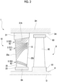
Fig. 2 is an enlarged cross-sectional view of a main part of the steam turbine according to the embodiment of the present disclosure. -
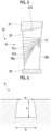
Fig. 3 is a cross-sectional view showing a shape of fine grooves according to the embodiment of the present disclosure. -
Fig. 4 is a view showing a first modification example of a turbine stator blade according to the embodiment of the present disclosure. -
Fig. 5 is a view showing a second modification example of the turbine stator blade according to the embodiment of the present disclosure. -
Fig. 6 is a cross-sectional view showing a first modification example of the fine grooves according to the embodiment of the present disclosure. -
Fig. 7 is a cross-sectional view showing a second modification example of the fine grooves according to the embodiment of the present disclosure. -
Fig. 8 is a cross-sectional view showing a third modification example of the fine grooves according to the embodiment of the present disclosure. -
Fig. 9 is a cross-sectional view showing a fourth modification example of the fine grooves according to the embodiment of the present disclosure. - Hereinafter, a
steam turbine 1 and a stator blade 10 (a turbine stator blade) according to an embodiment of the present disclosure will be described with reference toFigs. 1 and2 . As shown inFig. 1 , thesteam turbine 1 includes arotor 2 and acasing 3. - The
rotor 2 has a rotatingshaft 6 having a circular cross section extending along an axis O, and a plurality of rotor blade rows 7 provided on an outer peripheral surface of the rotatingshaft 6. The rotatingshaft 6 is rotatable around the axis O. The plurality of rotor blade rows 7 are arranged at intervals in an axis O direction. Each rotor blade row 7 has a plurality ofrotor blades 8 arranged in a circumferential direction of the axis O. Therotor blade 8 extends radially outward from the outer peripheral surface of the rotatingshaft 6. A detailed configuration of therotor blade 8 will be described later. - The
casing 3 has acasing body 3H that covers therotor 2 from an outer peripheral side, and a plurality ofstator blade rows 9 supported from the outer peripheral side and an inner peripheral side by an outer ring 21 (described later) and an inner ring 23 (described later) provided on an inner peripheral side of thecasing body 3H. Thecasing body 3H has a tubular shape centered on the axis O. The plurality ofstator blade rows 9 are arranged at intervals in the axis O direction. Thesteam turbine 1 includes the same number of rotor blade rows 7 as thestator blade rows 9, and one rotor blade row 7 is located between a pair of thestator blade rows 9 adjacent to each other in the axis O direction. That is, the rotor blade rows 7 and thestator blade rows 9 are alternately arranged in the axis O direction. Onestator blade row 9 and one rotor blade row 7 form one "stage". Eachstator blade row 9 has a plurality ofstator blades 10 arranged in the circumferential direction of the axis O. Thestator blade 10 extends in a radial direction with respect to the axis O. - A
steam flow path 11 for taking high-temperature and high-pressure steam guided from an inlet pipe into the stage of thecasing body 3H is formed on one side of thecasing body 3H in the axis O direction. Anexhaust hood 12 responsible for collecting a pressure of the steam is provided on the other side of thecasing body 3H in the axis O direction. - The steam that has flowed into the
steam flow path 11 flows through the stages in thecasing body 3H, then passes through theexhaust hood 12, and is sent to a condenser (not shown). In the following description, a side on which thesteam flow path 11 is located as viewed from theexhaust hood 12 will be referred to as an upstream side in a flow direction of the steam. A side on which theexhaust hood 12 is located as viewed from thesteam flow path 11 is referred to as a downstream side. - As shown in
Fig. 2 , therotor blade 8 includes aplatform 81, arotor blade body 82, and ashroud 83. Theplatform 81 is installed on the outer peripheral surface of the rotating shaft 6 (rotating shaft outerperipheral surface 6A). Therotor blade body 82 is provided on an outer peripheral side of theplatform 81. Therotor blade body 82 extends in the radial direction and has a blade-shaped cross-sectional shape when viewed in the radial direction. As an example, therotor blade body 82 is formed so that a dimension in the axis O direction gradually decreases from an inner side to an outer side in the radial direction. Theshroud 83 is provided at an end portion on a radially outer side of therotor blade body 82. Theshroud 83 has a substantially rectangular cross-sectional shape having the axis O direction as a longitudinal direction. An outer peripheral surface of theshroud 83 faces an inner peripheral surface (casing innerperipheral surface 3A) of thecasing body 3H at an interval in the radial direction. - The
stator blade 10 has theouter ring 21, a stator blade body 22 (blade body), and theinner ring 23. In addition, thestator blade body 22 has acentral region 41, anouter region 42, aninner region 43, and a slit 13 (collecting portion 14). Theouter ring 21 has an annular shape centered on the axis O. Theouter ring 21 is supported by thecasing body 3H via a support member (not shown). Thestator blade body 22 is fixed between theouter ring 21 and theinner ring 23. Thestator blade body 22 extends radially inward from an outer ring innerperipheral surface 21A and has a blade-shaped cross-sectional shape when viewed in the radial direction. That is, thestator blade body 22 extends in a direction intersecting the flow direction of the steam. As an example, a dimension of thestator blade body 22 in the axis O direction gradually decreases from the outer side to the inner side in the radial direction. Theinner ring 23 is provided at an end portion on a radially inner side of thestator blade body 22. Theinner ring 23 has a substantially rectangular cross-sectional shape having the axis O direction as a longitudinal direction. An inner peripheral surface of theinner ring 23 faces the rotating shaft outerperipheral surface 6A at an interval in the radial direction. - The
central region 41, theouter region 42, theinner region 43, and theslit 13 are formed on a surface of the stator blade body 22 (more specifically, a surface facing the upstream side of both surfaces of thestator blade body 22 in a thickness direction: a pressure side). A plurality offine grooves 5 recessed inward from the surface of thestator blade body 22 are formed in thecentral region 41, theouter region 42, and theinner region 43. Thefine grooves 5 are provided to transfer droplets generated on the surface of thestator blade body 22 to the downstream side along a flow of the steam. Thefine grooves 5 are arranged at intervals in the radial direction. - Regarding the fine grooves 5 (first fine grooves 51) formed in the
central region 41, intervals between the firstfine grooves 51 adjacent to each other decrease from aleading edge 22a side to a trailingedge 22b side of thestator blade body 22. That is, a dimension of thecentral region 41 gradually decreases in the radial direction from theleading edge 22a side toward the trailingedge 22b side. End portions of the firstfine grooves 51 on the downstream side communicate with theslit 13 described later. - The
outer region 42 is formed radially outward of thecentral region 41. The fine grooves 5 (second fine grooves 52) formed in theouter region 42 are curved toward the outer side in the radial direction from theleading edge 22a side toward the downstream side. End portion of the secondfine grooves 52 on the downstream side are connected to the inner peripheral surface of theouter ring 21. - The
inner region 43 is formed radially inward of thecentral region 41. The fine grooves 5 (third fine grooves 53) formed in theinner region 43 are curved toward the inner side in the radial direction from theleading edge 22a side toward the downstream side. End portion of the thirdfine grooves 53 on the downstream side extend to a radially inner region (vicinity of the inner ring 23) in the trailingedge 22b. - On the
leading edge 22a side, the central region 41 (first fine grooves 51) occupies the largest ratio, and theouter region 42 and theinner region 43 occupy a smaller area than thecentral region 41. - On a trailing
edge 22b side of thecentral region 41, theslit 13 is formed as a collectingportion 14 for collecting a liquid film that has flowed through the firstfine grooves 51. Theslit 13 extends along the trailingedge 22b. Theslit 13 is one or more elongated holes communicating with an inside of thestator blade body 22. That is, thestator blade body 22 is hollow. It is desirable that an internal space of thestator blade body 22 is brought into a negative pressure state by a device (not shown). - Next, dimensions of the
fine grooves 5 will be described with reference toFig. 3 . As shown in the figure, in the present embodiment, thefine groove 5 has a rectangular cross-sectional shape. In a case where the interval (pitch) between the adjacentfine groove 5 is p, a depth of thefine groove 5 is h, a width of an opening is w, and a width of a bottom surface part is b, it is desirable that a value of w is 0.3 to 2.0 mm. In addition, it is desirable that a value of b/w is 0 to 2.0 (although details will be described later, a case where the value is 0 corresponds to a case where thefine groove 5 has a triangular cross section). Furthermore, it is desirable that a value of h/w is 0.5 to 2.0. A value of p/w is desirably 0.5 to 3.0. - Subsequently, an operation of the
steam turbine 1 and a behavior of the droplets on thestator blade 10 according to the present embodiment will be described. In operating thesteam turbine 1, first, high-temperature and high-pressure steam is introduced into an inside of thecasing body 3H through thesteam flow path 11. The steam alternately passes through the above-describedstator blade rows 9 and rotor blade rows 7 while flowing toward the downstream side inside thecasing body 3H. Thestator blade row 9 rectifies the flow of the steam to cause the steam to flow into the adjacent rotor blade row 7 on the downstream side. By the steam acting on the rotor blade row 7, torque is applied to therotating shaft 6 through the rotor blade row 7. Due to this torque, therotor 2 rotates around the axis O. Rotational energy of therotor 2 is taken out from a shaft end and is used for driving a generator (not shown) or the like. - Here, energy of the steam passing through the stage in a main flow path of the turbine is converted into rotational energy each time the steam passes through the stage from the upstream side toward the downstream side, resulting in a decrease in temperature (and pressure). Therefore, in the
stator blade row 9 on the most downstream side, a portion of the steam is liquefied and exists in an air flow as fine droplets, and a portion of the droplets adheres to the surface of the stator blade 10 (the stator blade body 22). These droplets grow to form a liquid film. Furthermore, when the liquid film flows downstream and increases in thickness as the number of droplets continues to increase, a portion of the liquid film is torn off by the steam flow, or the liquid film that remains adhering to the stator blade row scatters as coarse droplets from the trailing edge of the stator blade. The scattering droplets flow toward the downstream side while gradually accelerating due to the steam flow. When the coarse droplets collide with therotor blade 8 on the downstream side, erosion may occur on a surface of therotor blade 8. In addition, the collision of the droplets may hinder rotation of the rotor blade 8 (rotor 2), resulting in braking loss. - Therefore, in the present embodiment, the plurality of
fine grooves 5 are formed on the surface of thestator blade body 22 as described above. The droplets captured in thefine grooves 5 flow toward the downstream side along with the flow of the steam. In thecentral region 41, the droplets flow toward theslit 13 along the firstfine grooves 51. The droplets are collected by a negative pressure of theslit 13. In addition, in theouter region 42, the droplets flow toward the outer side in the radial direction along the secondfine grooves 52 and are guided to the inner peripheral surface of theouter ring 21. That is, the droplets do not reach therotor blade 8 on the downstream side. Similarly, in theinner region 43, the droplets flow toward the inner side in the radial direction along the thirdfine grooves 53. Accordingly, the droplets do not reach a tip portion of therotor blade 8 having a high circumferential speed. - In particular, according to the above configuration, the intervals between the first
fine grooves 51 decrease from the upstream side toward the collecting portion 14 (slit 13). Accordingly, the liquid film or droplets can be guided toward the collectingportion 14 from a wider range on the upstream side. In addition, accordingly, a size of the collectingportion 14 itself can be minimized. As a result, a possibility that the collectingportion 14 affects a mainstream of the steam can be reduced compared to a case where alarge collecting portion 14 is secured. - In addition, according to the above configuration, the liquid film generated on the outer side in the radial direction from the
central region 41 can be further guided toward the outer side in the radial direction (for example, the inner peripheral surface of the outer ring 21) by the secondfine grooves 52. Accordingly, a possibility that the droplets are scattered toward a downstream side of thestator blade body 22 can be further reduced. - Furthermore, according to the above configuration, the liquid film generated on the inner side in the radial direction from the
central region 41 can be further guided toward the inner side in the radial direction by the thirdfine grooves 53. Accordingly, the possibility that the droplets are scattered toward the downstream side of thestator blade body 22 can be further reduced. - Hereinabove, the embodiment of the present disclosure has been described. In addition, various changes and modifications of the above-described configuration can be made without departing from the gist of the present disclosure.
- For example, a configuration shown in
Fig. 4 can be adopted as a first modification example of thestator blade 10. In the first modification example, firstfine grooves 51b are curved toward the outer side in the radial direction from theleading edge 22a side toward theslit 13 side. Furthermore, a turning angle, which is an angle formed by a direction in which the firstfine grooves 51b extend with respect to a flow direction F of the steam, gradually decreases toward theslit 13. That is, a portion of the firstfine grooves 51b on theslit 13 side has a larger radius of curvature than a portion of the firstfine grooves 51b on theleading edge 22a side. In other words, a rate of increase in the turning angle gradually decreases from theleading edge 22a side toward theslit 13 side. It is also possible to form the portion of the firstfine grooves 51b on theslit 13 side as a clothoid curve. - According to the above configuration, the direction in which the first
fine grooves 51b extend changes along the flow direction of the steam toward theslit 13. Accordingly, a flow velocity of the liquid film increases toward theslit 13, and the liquid film can be collected more efficiently. - Furthermore, it is also possible to adopt a configuration shown in
Fig. 5 as a second modification example of thestator blade 10. In the second modification example,main grooves 51c and sub-grooves 51d are formed as thefine grooves 5 in thecentral region 41. Themain grooves 51c extend from theleading edge 22a side toward theslit 13, and an interval between themain grooves 51c adjacent to each other decreases. The sub-grooves 51d join one of themain grooves 51c at an end point starting from theleading edge 22a side. Even with such a configuration, it is possible to collect the liquid film in a wider range on theleading edge 22a side. - In addition, in the above-described embodiment, the example in which the
fine groove 5 has a rectangular cross-sectional shape has been described. However, the shape of thefine groove 5 can be variously changed as long as the above-mentioned dimensional conditions are satisfied. For example, as shown inFig. 6 , the width b of the bottom surface part can also be made larger than the width w of the opening (b > w). As shown inFig. 7 , the width b of the bottom surface part can also be made smaller than the width w of the opening (b < w). As shown inFig. 8 , the cross-sectional shape of thefine groove 5 can be made triangular (b = 0). Furthermore, as shown inFig. 9 , the bottom surface part can be made in an arc shape. - A device X described in each embodiment is grasped as follows, for example.
- (1) The turbine stator blade (stator blade 10) according to a first aspect includes: the
stator blade body 22 extending in the radial direction intersecting the flow direction of the steam; the collectingportion 14 formed on the surface of thestator blade body 22 and collecting the liquid film flowing along the surface; and thecentral region 41 formed on the surface of thestator blade body 22 and formed with the plurality of firstfine grooves 51 extending from the upstream side in the flow direction toward the collectingportion 14, in which the intervals between the firstfine grooves 51 adjacent to each other decrease from the upstream side toward the collectingportion 14. - According to the above configuration, the intervals between the first
fine grooves 51 decrease from the upstream side toward the collectingportion 14. Accordingly, the liquid film can be guided toward the collectingportion 14 from a wider range on the upstream side. In addition, the size of the collectingportion 14 itself can be minimized. Accordingly, the possibility that the steam affects the mainstream of the steam can be reduced. - (2) In the turbine stator blade (stator blade 10) according to a second aspect, the turning angle, which is the angle formed by the direction in which the first
fine grooves 51b extend with respect to the flow direction, may gradually decrease toward the collectingportion 14. - According to the above configuration, the direction in which the first
fine grooves 51b extend changes along the flow direction of the steam toward the collectingportion 14. Accordingly, the flow velocity of the liquid film increases toward the collectingportion 14, and the liquid film can be collected more efficiently. - (3) In the turbine stator blade (stator blade 10) according to a third aspect, a rate of increase in the turning angle, which is the angle formed by the direction in which the first
fine grooves 51b extend with respect to the flow direction, may gradually decrease toward the collectingportion 14. - According to the above configuration, the rate of increase in the turning angle of the first
fine grooves 51b gradually decreases toward the collectingportion 14. Accordingly, the flow velocity of the liquid film increases toward the collectingportion 14, and the liquid film can be collected more efficiently. - (4) The turbine stator blade (stator blade 10) according to a fourth aspect may further include: the
outer region 42 formed radially outward of thecentral region 41 on the surface of thestator blade body 22 and formed with a plurality of the secondfine grooves 52 extending radially outward from the upstream side toward the downstream side. - According to the above configuration, the liquid film generated on the outer side in the radial direction from the
central region 41 can be further guided toward the outer side in the radial direction (for example, the inner peripheral surface of the outer ring 21) by the secondfine grooves 52. Accordingly, the possibility that the droplets are scattered toward the downstream side of thestator blade body 22 can be further reduced. - (5) The turbine stator blade (stator blade 10) according to a fifth aspect may further include: the
inner region 43 formed radially inward of thecentral region 41 on the surface of thestator blade body 22 and formed with a plurality of the thirdfine grooves 53 extending radially inward from the upstream side toward the downstream side. - According to the above configuration, the liquid film generated on the inner side in the radial direction from the
central region 41 can be further guided toward the inner side in the radial direction by the thirdfine grooves 53. Accordingly, the possibility that the droplets are scattered toward the downstream side of thestator blade body 22 can be further reduced. - (6) The
steam turbine 1 according to a sixth aspect includes: the rotatingshaft 6 extending along the axis O; a plurality of the turbine rotor blades (rotor blades 8) extending radially outward from the outer peripheral surface of therotating shaft 6 and arranged in the circumferential direction; thecasing 3 that covers therotating shaft 6 and the plurality of turbine rotor blades from the outer side; and a plurality of the turbine stator blades (stator blades 10) according to any one of the first to fifth aspects, extending radially inward from the inner peripheral surface of thecasing 3 and arranged in the circumferential direction. - According to the above configuration, it is possible to provide the
steam turbine 1 in which generation of erosion due to the droplets being scattered toward the downstream side is suppressed. - According to the present disclosure, it is possible to provide a turbine stator blade and a steam turbine capable of suppressing or collecting droplets more efficiently.
-
- 1: Steam turbine
- 2: Rotor
- 3: Casing
- 3A: Casing inner peripheral surface
- 3H: Casing body
- 5: Fine groove
- 6: Rotating shaft
- 6A: Rotating shaft outer peripheral surface
- 7: Rotor blade row
- 8: Rotor blade (turbine rotor blade)
- 9: Stator blade row
- 10: Stator blade (turbine stator blade)
- 11: Steam flow path
- 12: Exhaust hood
- 13: Slit
- 14: Collecting portion
- 21: Outer ring
- 21A: Outer ring inner peripheral surface
- 22: Stator blade body (blade body)
- 22a: Front edge
- 22b: Trailing edge
- 23: Inner ring
- 41: Central region
- 42: Outer region
- 43: Inner region
- 51,51b: First fine groove
- 51c: Main groove
- 51d: Sub-groove
- 52: Second fine groove
- 53: Third fine groove
- 81: Platform
- 82: Rotor blade body
- 83: Shroud
- O: Axis
Claims (6)
- A turbine stator blade comprising:a stator blade body extending in a radial direction intersecting a flow direction of steam;a collecting portion formed on a surface of the stator blade body and collecting a liquid film flowing along the surface; anda central region formed on the surface of the stator blade body and formed with a plurality of first fine grooves extending from an upstream side in the flow direction toward the collecting portion,wherein intervals between the first fine grooves adjacent to each other decrease from the upstream side toward the collecting portion.
- The turbine stator blade according to claim 1,
wherein a turning angle, which is an angle formed by a direction in which the first fine grooves extend with respect to the flow direction, gradually decreases toward the collecting portion. - The turbine stator blade according to claim 1,
wherein a rate of increase in a turning angle, which is an angle formed by a direction in which the first fine grooves extend with respect to the flow direction, gradually decreases toward the collecting portion. - The turbine stator blade according to any one of claims 1 to 3, further comprising:
an outer region formed radially outward of the central region on the surface of the stator blade body and formed with a plurality of second fine grooves extending radially outward from the upstream side toward a downstream side. - The turbine stator blade according to any one of claims 1 to 4, further comprising:
an inner region formed radially inward of the central region on the surface of the stator blade body and formed with a plurality of third fine grooves extending radially inward from the upstream side toward a downstream side. - A steam turbine comprising:a rotating shaft extending along an axis;a plurality of turbine rotor blades extending radially outward from an outer peripheral surface of the rotating shaft and arranged in a circumferential direction;a casing that covers the rotating shaft and the plurality of turbine rotor blades from an outer side; anda plurality of the turbine stator blades according to any one of claims 1 to 5, extending radially inward from an inner peripheral surface of the casing and arranged in the circumferential direction.
Applications Claiming Priority (2)
| Application Number | Priority Date | Filing Date | Title |
|---|---|---|---|
| JP2021106944 | 2021-06-28 | ||
| PCT/JP2022/015932 WO2023276385A1 (en) | 2021-06-28 | 2022-03-30 | Turbine stator vane and steam turbine |
Publications (3)
| Publication Number | Publication Date |
|---|---|
| EP4212705A1 true EP4212705A1 (en) | 2023-07-19 |
| EP4212705A4 EP4212705A4 (en) | 2023-11-29 |
| EP4212705B1 EP4212705B1 (en) | 2025-07-23 |
Family
ID=84692662
Family Applications (1)
| Application Number | Title | Priority Date | Filing Date |
|---|---|---|---|
| EP22832546.0A Active EP4212705B1 (en) | 2021-06-28 | 2022-03-30 | Turbine stator vane and steam turbine |
Country Status (6)
| Country | Link |
|---|---|
| US (1) | US12037927B2 (en) |
| EP (1) | EP4212705B1 (en) |
| JP (1) | JP7527487B2 (en) |
| KR (1) | KR20230088458A (en) |
| CN (1) | CN116368288B (en) |
| WO (1) | WO2023276385A1 (en) |
Family Cites Families (21)
| Publication number | Priority date | Publication date | Assignee | Title |
|---|---|---|---|---|
| JPS63183205A (en) | 1987-01-23 | 1988-07-28 | Hitachi Ltd | Turbomachinery rotor blade erosion prevention device |
| JPS63263204A (en) * | 1987-04-21 | 1988-10-31 | Toshiba Corp | Erosion prevention device for turbine blade |
| JPS6480705A (en) * | 1987-09-24 | 1989-03-27 | Hitachi Ltd | Stationary blade construction for steam turbine |
| DE19546008A1 (en) * | 1995-12-09 | 1997-06-12 | Abb Patent Gmbh | Turbine blade, which is intended for use in the wet steam area of pre-output and output stages of turbines |
| JPH10299410A (en) | 1997-04-22 | 1998-11-10 | Hitachi Ltd | Moisture discharge structure of steam turbine |
| JP4886271B2 (en) * | 2005-10-31 | 2012-02-29 | 株式会社東芝 | Steam turbine and hydrophilic coating material thereof |
| JP2013155725A (en) | 2012-02-01 | 2013-08-15 | Hitachi Ltd | Steam turbine and stationary blade of steam turbine |
| JP5968173B2 (en) * | 2012-09-14 | 2016-08-10 | 三菱日立パワーシステムズ株式会社 | Steam turbine stationary blade and steam turbine |
| PL2985426T3 (en) * | 2014-08-12 | 2021-01-11 | Siemens Aktiengesellschaft | Blade device for a turbine and corresponding manufacturing method |
| JP6393178B2 (en) * | 2014-12-15 | 2018-09-19 | 三菱日立パワーシステムズ株式会社 | Steam turbine stationary blade |
| JP2016166569A (en) | 2015-03-09 | 2016-09-15 | 株式会社東芝 | Steam turbine |
| JP2017020443A (en) | 2015-07-13 | 2017-01-26 | 株式会社東芝 | Nozzle for steam turbine and steam turbine provided with the nozzle |
| JP6507460B2 (en) * | 2015-08-21 | 2019-05-08 | 三菱重工コンプレッサ株式会社 | Steam turbine |
| US10781722B2 (en) | 2015-12-11 | 2020-09-22 | General Electric Company | Steam turbine, a steam turbine nozzle, and a method of managing moisture in a steam turbine |
| JP6637455B2 (en) * | 2017-02-10 | 2020-01-29 | 三菱日立パワーシステムズ株式会社 | Steam turbine |
| JP7148273B2 (en) * | 2018-05-21 | 2022-10-05 | 三菱重工業株式会社 | steam turbine |
| JP6873956B2 (en) | 2018-09-24 | 2021-05-19 | 株式会社藤商事 | Pachinko machine |
| JP7179652B2 (en) | 2019-02-27 | 2022-11-29 | 三菱重工業株式会社 | Turbine stator blades and steam turbines |
| JP7179651B2 (en) * | 2019-02-27 | 2022-11-29 | 三菱重工業株式会社 | Turbine stator blades and steam turbines |
| JP7378970B2 (en) * | 2019-06-10 | 2023-11-14 | 三菱重工業株式会社 | Steam turbine stationary blade, steam turbine and steam turbine stationary blade manufacturing method |
| US11773753B2 (en) | 2019-12-11 | 2023-10-03 | Mitsubishi Heavy Industries, Ltd. | Turbine stator vane, turbine stator vane assembly, and steam turbine |
-
2022
- 2022-03-30 KR KR1020237016526A patent/KR20230088458A/en active Pending
- 2022-03-30 EP EP22832546.0A patent/EP4212705B1/en active Active
- 2022-03-30 US US18/032,054 patent/US12037927B2/en active Active
- 2022-03-30 CN CN202280006880.6A patent/CN116368288B/en active Active
- 2022-03-30 JP JP2023531452A patent/JP7527487B2/en active Active
- 2022-03-30 WO PCT/JP2022/015932 patent/WO2023276385A1/en not_active Ceased
Also Published As
| Publication number | Publication date |
|---|---|
| JPWO2023276385A1 (en) | 2023-01-05 |
| US12037927B2 (en) | 2024-07-16 |
| KR20230088458A (en) | 2023-06-19 |
| EP4212705B1 (en) | 2025-07-23 |
| JP7527487B2 (en) | 2024-08-02 |
| CN116368288A (en) | 2023-06-30 |
| WO2023276385A1 (en) | 2023-01-05 |
| CN116368288B (en) | 2025-08-22 |
| EP4212705A4 (en) | 2023-11-29 |
| US20230392510A1 (en) | 2023-12-07 |
Similar Documents
| Publication | Publication Date | Title |
|---|---|---|
| CN101563526B (en) | Diffuser and exhaust system for turbine | |
| EP4036380B1 (en) | Turbine stator vane assembly and steam turbine | |
| CN111287801B (en) | Steam turbine | |
| JP2008128064A (en) | Mixed flow turbine or radial turbine | |
| EP2226471B1 (en) | Working fluid extraction in an axial turbine | |
| CN113383147B (en) | Rotary machine | |
| JP6518526B2 (en) | Axial flow turbine | |
| US12221900B2 (en) | Stationary turbine blade and steam turbine | |
| US12037927B2 (en) | Turbine stator vane and steam turbine | |
| US11131201B2 (en) | Rotor blade, rotor unit, and rotating machine | |
| JP7368260B2 (en) | turbine | |
| JP4184565B2 (en) | Steam turbine nozzle and steam turbine using the steam turbine nozzle | |
| JP5591142B2 (en) | Extraction structure of rotating machine | |
| JPH11173104A (en) | Turbine blade | |
| CN117027962B (en) | Steam turbine and its stator blades | |
| CN114127389B (en) | Axial turbine | |
| JP2014095309A (en) | Steam turbine | |
| JPS6332963B2 (en) | ||
| JP2004068771A (en) | Axial compressor stationary vanes | |
| JP2025145568A (en) | Steam turbine blade and steam turbine | |
| JP2017203410A (en) | Supercharger | |
| JP2007138864A (en) | Steam turbine stage and steam turbine | |
| WO2025126895A1 (en) | Axial turbine | |
| JPWO2001077499A1 (en) | Steam turbine and its moisture separation structure | |
| CN113374532A (en) | Steam turbine |
Legal Events
| Date | Code | Title | Description |
|---|---|---|---|
| STAA | Information on the status of an ep patent application or granted ep patent |
Free format text: STATUS: THE INTERNATIONAL PUBLICATION HAS BEEN MADE |
|
| PUAI | Public reference made under article 153(3) epc to a published international application that has entered the european phase |
Free format text: ORIGINAL CODE: 0009012 |
|
| STAA | Information on the status of an ep patent application or granted ep patent |
Free format text: STATUS: REQUEST FOR EXAMINATION WAS MADE |
|
| 17P | Request for examination filed |
Effective date: 20230413 |
|
| AK | Designated contracting states |
Kind code of ref document: A1 Designated state(s): AL AT BE BG CH CY CZ DE DK EE ES FI FR GB GR HR HU IE IS IT LI LT LU LV MC MK MT NL NO PL PT RO RS SE SI SK SM TR |
|
| A4 | Supplementary search report drawn up and despatched |
Effective date: 20231027 |
|
| RIC1 | Information provided on ipc code assigned before grant |
Ipc: F01D 25/32 20060101ALI20231023BHEP Ipc: F01D 9/02 20060101AFI20231023BHEP |
|
| DAV | Request for validation of the european patent (deleted) | ||
| DAX | Request for extension of the european patent (deleted) | ||
| GRAP | Despatch of communication of intention to grant a patent |
Free format text: ORIGINAL CODE: EPIDOSNIGR1 |
|
| STAA | Information on the status of an ep patent application or granted ep patent |
Free format text: STATUS: GRANT OF PATENT IS INTENDED |
|
| INTG | Intention to grant announced |
Effective date: 20250213 |
|
| GRAS | Grant fee paid |
Free format text: ORIGINAL CODE: EPIDOSNIGR3 |
|
| GRAA | (expected) grant |
Free format text: ORIGINAL CODE: 0009210 |
|
| STAA | Information on the status of an ep patent application or granted ep patent |
Free format text: STATUS: THE PATENT HAS BEEN GRANTED |
|
| AK | Designated contracting states |
Kind code of ref document: B1 Designated state(s): AL AT BE BG CH CY CZ DE DK EE ES FI FR GB GR HR HU IE IS IT LI LT LU LV MC MK MT NL NO PL PT RO RS SE SI SK SM TR |
|
| REG | Reference to a national code |
Ref country code: GB Ref legal event code: FG4D |
|
| REG | Reference to a national code |
Ref country code: CH Ref legal event code: EP |
|
| REG | Reference to a national code |
Ref country code: DE Ref legal event code: R096 Ref document number: 602022018213 Country of ref document: DE |
|
| REG | Reference to a national code |
Ref country code: IE Ref legal event code: FG4D |
|
| REG | Reference to a national code |
Ref country code: CH Ref legal event code: R17 Free format text: ST27 STATUS EVENT CODE: U-0-0-R10-R17 (AS PROVIDED BY THE NATIONAL OFFICE) Effective date: 20251113 |
|
| REG | Reference to a national code |
Ref country code: NL Ref legal event code: MP Effective date: 20250723 |
|
| PG25 | Lapsed in a contracting state [announced via postgrant information from national office to epo] |
Ref country code: PT Free format text: LAPSE BECAUSE OF FAILURE TO SUBMIT A TRANSLATION OF THE DESCRIPTION OR TO PAY THE FEE WITHIN THE PRESCRIBED TIME-LIMIT Effective date: 20251124 |
|
| PG25 | Lapsed in a contracting state [announced via postgrant information from national office to epo] |
Ref country code: NL Free format text: LAPSE BECAUSE OF FAILURE TO SUBMIT A TRANSLATION OF THE DESCRIPTION OR TO PAY THE FEE WITHIN THE PRESCRIBED TIME-LIMIT Effective date: 20250723 |
|
| REG | Reference to a national code |
Ref country code: AT Ref legal event code: MK05 Ref document number: 1816612 Country of ref document: AT Kind code of ref document: T Effective date: 20250723 |
|
| PG25 | Lapsed in a contracting state [announced via postgrant information from national office to epo] |
Ref country code: IS Free format text: LAPSE BECAUSE OF FAILURE TO SUBMIT A TRANSLATION OF THE DESCRIPTION OR TO PAY THE FEE WITHIN THE PRESCRIBED TIME-LIMIT Effective date: 20251123 |
|
| PG25 | Lapsed in a contracting state [announced via postgrant information from national office to epo] |
Ref country code: NO Free format text: LAPSE BECAUSE OF FAILURE TO SUBMIT A TRANSLATION OF THE DESCRIPTION OR TO PAY THE FEE WITHIN THE PRESCRIBED TIME-LIMIT Effective date: 20251023 |
|
| REG | Reference to a national code |
Ref country code: LT Ref legal event code: MG9D |
|
| PG25 | Lapsed in a contracting state [announced via postgrant information from national office to epo] |
Ref country code: AT Free format text: LAPSE BECAUSE OF FAILURE TO SUBMIT A TRANSLATION OF THE DESCRIPTION OR TO PAY THE FEE WITHIN THE PRESCRIBED TIME-LIMIT Effective date: 20250723 |
|
| PG25 | Lapsed in a contracting state [announced via postgrant information from national office to epo] |
Ref country code: FI Free format text: LAPSE BECAUSE OF FAILURE TO SUBMIT A TRANSLATION OF THE DESCRIPTION OR TO PAY THE FEE WITHIN THE PRESCRIBED TIME-LIMIT Effective date: 20250723 |
|
| PG25 | Lapsed in a contracting state [announced via postgrant information from national office to epo] |
Ref country code: HR Free format text: LAPSE BECAUSE OF FAILURE TO SUBMIT A TRANSLATION OF THE DESCRIPTION OR TO PAY THE FEE WITHIN THE PRESCRIBED TIME-LIMIT Effective date: 20250723 |
|
| PG25 | Lapsed in a contracting state [announced via postgrant information from national office to epo] |
Ref country code: GR Free format text: LAPSE BECAUSE OF FAILURE TO SUBMIT A TRANSLATION OF THE DESCRIPTION OR TO PAY THE FEE WITHIN THE PRESCRIBED TIME-LIMIT Effective date: 20251024 |
|
| PG25 | Lapsed in a contracting state [announced via postgrant information from national office to epo] |
Ref country code: SE Free format text: LAPSE BECAUSE OF FAILURE TO SUBMIT A TRANSLATION OF THE DESCRIPTION OR TO PAY THE FEE WITHIN THE PRESCRIBED TIME-LIMIT Effective date: 20250723 |
|
| PG25 | Lapsed in a contracting state [announced via postgrant information from national office to epo] |
Ref country code: LV Free format text: LAPSE BECAUSE OF FAILURE TO SUBMIT A TRANSLATION OF THE DESCRIPTION OR TO PAY THE FEE WITHIN THE PRESCRIBED TIME-LIMIT Effective date: 20250723 |
|
| PG25 | Lapsed in a contracting state [announced via postgrant information from national office to epo] |
Ref country code: PL Free format text: LAPSE BECAUSE OF FAILURE TO SUBMIT A TRANSLATION OF THE DESCRIPTION OR TO PAY THE FEE WITHIN THE PRESCRIBED TIME-LIMIT Effective date: 20250723 Ref country code: BG Free format text: LAPSE BECAUSE OF FAILURE TO SUBMIT A TRANSLATION OF THE DESCRIPTION OR TO PAY THE FEE WITHIN THE PRESCRIBED TIME-LIMIT Effective date: 20250723 |
|
| PG25 | Lapsed in a contracting state [announced via postgrant information from national office to epo] |
Ref country code: RS Free format text: LAPSE BECAUSE OF FAILURE TO SUBMIT A TRANSLATION OF THE DESCRIPTION OR TO PAY THE FEE WITHIN THE PRESCRIBED TIME-LIMIT Effective date: 20251023 |
|
| PG25 | Lapsed in a contracting state [announced via postgrant information from national office to epo] |
Ref country code: ES Free format text: LAPSE BECAUSE OF FAILURE TO SUBMIT A TRANSLATION OF THE DESCRIPTION OR TO PAY THE FEE WITHIN THE PRESCRIBED TIME-LIMIT Effective date: 20250723 |
|
| REG | Reference to a national code |
Ref country code: CH Ref legal event code: U11 Free format text: ST27 STATUS EVENT CODE: U-0-0-U10-U11 (AS PROVIDED BY THE NATIONAL OFFICE) Effective date: 20260401 |
|
| PG25 | Lapsed in a contracting state [announced via postgrant information from national office to epo] |
Ref country code: SM Free format text: LAPSE BECAUSE OF FAILURE TO SUBMIT A TRANSLATION OF THE DESCRIPTION OR TO PAY THE FEE WITHIN THE PRESCRIBED TIME-LIMIT Effective date: 20250723 |
|
| PG25 | Lapsed in a contracting state [announced via postgrant information from national office to epo] |
Ref country code: DK Free format text: LAPSE BECAUSE OF FAILURE TO SUBMIT A TRANSLATION OF THE DESCRIPTION OR TO PAY THE FEE WITHIN THE PRESCRIBED TIME-LIMIT Effective date: 20250723 |
|
| PGFP | Annual fee paid to national office [announced via postgrant information from national office to epo] |
Ref country code: DE Payment date: 20260204 Year of fee payment: 5 |
|
| PGFP | Annual fee paid to national office [announced via postgrant information from national office to epo] |
Ref country code: IT Payment date: 20260220 Year of fee payment: 5 |
|
| PG25 | Lapsed in a contracting state [announced via postgrant information from national office to epo] |
Ref country code: CZ Free format text: LAPSE BECAUSE OF FAILURE TO SUBMIT A TRANSLATION OF THE DESCRIPTION OR TO PAY THE FEE WITHIN THE PRESCRIBED TIME-LIMIT Effective date: 20250723 |
|
| PG25 | Lapsed in a contracting state [announced via postgrant information from national office to epo] |
Ref country code: EE Free format text: LAPSE BECAUSE OF FAILURE TO SUBMIT A TRANSLATION OF THE DESCRIPTION OR TO PAY THE FEE WITHIN THE PRESCRIBED TIME-LIMIT Effective date: 20250723 Ref country code: SK Free format text: LAPSE BECAUSE OF FAILURE TO SUBMIT A TRANSLATION OF THE DESCRIPTION OR TO PAY THE FEE WITHIN THE PRESCRIBED TIME-LIMIT Effective date: 20250723 |