JP2017203410A - Supercharger - Google Patents
Supercharger Download PDFInfo
- Publication number
- JP2017203410A JP2017203410A JP2016095186A JP2016095186A JP2017203410A JP 2017203410 A JP2017203410 A JP 2017203410A JP 2016095186 A JP2016095186 A JP 2016095186A JP 2016095186 A JP2016095186 A JP 2016095186A JP 2017203410 A JP2017203410 A JP 2017203410A
- Authority
- JP
- Japan
- Prior art keywords
- impeller
- compressor
- blade
- air
- inlet
- Prior art date
- Legal status (The legal status is an assumption and is not a legal conclusion. Google has not performed a legal analysis and makes no representation as to the accuracy of the status listed.)
- Granted
Links
Images


Abstract
Description
この発明は過給機に関し、特に、コンプレッサインペラを備えた過給機に関する。 The present invention relates to a supercharger, and more particularly to a supercharger equipped with a compressor impeller.
従来の過給機としては、例えば、特許文献1に開示されたコンプレッサ及びこれを用いたターボチャージャが知られている。特許文献1に開示されたコンプレッサは、空気の入口部および圧縮空気の出口部を有するコンプレッサハウジングと、コンプレッサハウジング内に回転軸を中心として回転可能に収容配置されるインペラとを備える。このコンプレッサではコンプレッサハウジングの内壁面が滑らかに膨出形成されている。コンプレッサハウジングの内壁面とこの内壁面に対向するインペラの翼の径方向縁部との間のクリアランスが、翼の径方向縁部についての空気入口部側の端部領域と空気出口部側の端部領域との間の中間位置において最小である。 As a conventional turbocharger, for example, a compressor disclosed in Patent Document 1 and a turbocharger using the compressor are known. The compressor disclosed in Patent Document 1 includes a compressor housing having an air inlet portion and a compressed air outlet portion, and an impeller that is housed and arranged in the compressor housing so as to be rotatable about a rotation axis. In this compressor, the inner wall surface of the compressor housing is smoothly bulged. The clearance between the inner wall surface of the compressor housing and the radial edge of the impeller blades facing the inner wall surface is such that the end region on the air inlet side and the end on the air outlet side of the blade in the radial direction edge. It is the minimum at the intermediate position between the partial areas.
特許文献1に開示されたコンプレッサによれば、クリアランス領域を通過する空気量すなわち損失を低減して、高速回転するインペラとハウジングとの接触を回避しつつコンプレッサ効率を向上させることができるとしている。 According to the compressor disclosed in Patent Document 1, the amount of air passing through the clearance region, that is, the loss is reduced, and the compressor efficiency can be improved while avoiding contact between the impeller and the housing rotating at high speed.
しかしながら、特許文献1に開示されたコンプレッサは、クリアランス領域を通過する空気量の低減により損失を低減するものの、低速時における空気層のインペラからの剥離による失速が生じるという問題を解決しない。空気層のインペラからの剥離による失速は、サージを発生してコンプレッサの性能低下を招く要因の一つである。図7に示すように、例えば、インペラ翼62を有するコンプレッサインペラ61へ流入する空気の絶対速度をCとし、コンプレッサインペラ61の周速Uとすると、コンプレッサインペラ61へ流入する空気の相対速度はWである。低速時における空気層のコンプレッサインペラ61からの剥離は、インペラ翼62の中心線(キャンバーライン)Lとコンプレッサインペラ61へ向けて流入する空気の流入相対速度Wとが成す迎角αが大きくなるときに発生することが知られている。その理由は、低速時はインペラ翼62の前縁付近の流路断面積に対して空気流量が小さく、絶対速度Cが小さくなることで仰角αが大きくなるためである。そこで、低速時において迎角αが小さくなるインペラ翼を備えたコンプレッサインペラやコンプレッサインペラの入口径を縮小したコンプレッサインペラを採用すれば、低速時における空気流の剥離は防止できる。しかしながら、これらの対策はコンプレッサインペラにおけるインペラスロート(インペラ翼間の空気流路において最も流路断面積が小さい領域)の流路断面積の減少を余儀なくされ、高速時のコンプレッサの能力が低下するという問題を生じる。
However, although the compressor disclosed in Patent Document 1 reduces the loss by reducing the amount of air passing through the clearance region, it does not solve the problem of stalling due to separation of the air layer from the impeller at low speed. The stall due to the separation of the air layer from the impeller is one of the factors that cause a surge and reduce the performance of the compressor. As shown in FIG. 7, for example, when the absolute velocity of the air flowing into the
本発明は上記の問題点に鑑みてなされたもので、本発明の目的は、高速時のコンプレッサの能力を低下させることなく、低速時における空気層のインペラ翼からの剥離を抑制することができる過給機の提供にある。 The present invention has been made in view of the above-described problems, and an object of the present invention is to suppress separation of the air layer from the impeller blades at low speed without reducing the capacity of the compressor at high speed. The provision of turbochargers.
上記の課題を解決するために、本発明は、空気入口部と空気出口部を備えたコンプレッサハウジングと、前記コンプレッサハウジング内にて回転可能なコンプレッサインペラと、前記コンプレッサハウジングに設けられ、前記コンプレッサインペラと対向するシュラウド壁と、を備え、前記コンプレッサインペラは、ハブ部と、前記ハブ部の周方向に設けられ、前記空気入口部から前記空気出口部へ向けて延在する複数の第1インペラ翼と、を備え、前記ハブ部の周方向に互いに隣り合う一対の前記第1インペラ翼の前記コンプレッサインペラの回転方向前方に位置する一方の第1インペラ翼は、前記一対の第1インペラ翼とシュラウド壁とにより区画されるインペラスロート部から前記空気入口部側へ延在する入口側翼部を有し、前記入口側翼部は、前記第1インペラ翼の前記シュラウド壁と対向する外周縁から前記コンプレッサインペラの径方向内側に凹む凹部を有し、前記シュラウド壁は、前記第1インペラ翼の前記凹部と対向する位置に、前記凹部に対応する断面形状の環状の凸部を有することを特徴とする。 In order to solve the above problems, the present invention provides a compressor housing having an air inlet portion and an air outlet portion, a compressor impeller rotatable in the compressor housing, the compressor impeller provided in the compressor housing, A plurality of first impeller blades that are provided in a circumferential direction of the hub portion and extend from the air inlet portion toward the air outlet portion. One of the pair of first impeller blades that are adjacent to each other in the circumferential direction of the hub portion in the rotation direction of the compressor impeller, and the first impeller blade and the shroud of the pair of first impeller blades An inlet side wing extending from an impeller throat section partitioned by a wall to the air inlet section side, and the inlet The blade portion has a concave portion recessed inward in the radial direction of the compressor impeller from an outer peripheral edge facing the shroud wall of the first impeller blade, and the shroud wall is located at a position facing the concave portion of the first impeller blade. And having an annular convex portion having a cross-sectional shape corresponding to the concave portion.
本発明によれば、コンプレッサインペラの入口側翼部の凹部およびシュラウド壁の凸部に設けることにより、凹部および凸部における流路断面積は空気入口部における流路断面積と比較して小さくなる。低速時にコンプレッサインペラを通過する空気の流量は変化しないが、流路断面積の減少により凹部および凸部を通過する空気の速度が増大して、入口側翼部における空気層の剥離が抑制される。その結果、過給機の高速時のコンプレッサの能力を低下させることなく、低速時における空気層のインペラ翼からの剥離を抑制することができる。 According to the present invention, by providing the concave portion of the inlet side blade portion of the compressor impeller and the convex portion of the shroud wall, the cross-sectional area of the channel at the concave portion and the convex portion becomes smaller than the cross-sectional area of the flow channel at the air inlet portion. Although the flow rate of the air passing through the compressor impeller at low speed does not change, the reduction of the flow path cross-sectional area increases the speed of the air passing through the concave portion and the convex portion, and the separation of the air layer at the inlet side wing portion is suppressed. As a result, it is possible to suppress separation of the air layer from the impeller blades at low speed without reducing the capacity of the compressor at the high speed of the supercharger.
また、上記の過給機において、前記凹部は円弧状の凹部であり、前記凸部は円弧状の前記凹部に倣って断面円弧状に突出する凸部である構成としてもよい。
この場合、コンプレッサインペラを通過する空気は凹部および凸部を円滑に通過することができる。
In the supercharger, the concave portion may be an arc-shaped concave portion, and the convex portion may be a convex portion that protrudes in a circular arc shape following the arc-shaped concave portion.
In this case, the air passing through the compressor impeller can smoothly pass through the concave portion and the convex portion.
また、上記の過給機において、前記空気入口部における前記コンプレッサインペラと前記シュラウド壁との入口クリアランスに対する前記凹部の凹み量との比は、0より大きく3より小さい構成としてもよい。
この場合、コンプレッサインペラの入口側翼部における空気層の剥離をより抑制することができる。
In the supercharger, a ratio of a recess amount of the concave portion to an inlet clearance between the compressor impeller and the shroud wall at the air inlet portion may be greater than 0 and smaller than 3.
In this case, separation of the air layer at the inlet side wing of the compressor impeller can be further suppressed.
本発明によれば、高速時のコンプレッサの能力を低下させることなく、低速時における空気層のインペラ翼からの剥離を抑制することができる過給機を提供することができる。 ADVANTAGE OF THE INVENTION According to this invention, the supercharger which can suppress the peeling from the impeller blade | wing of an air layer at the time of low speed can be provided, without reducing the capability of the compressor at the time of high speed.
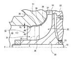
以下、本発明の実施形態に係る過給機としてのターボチャージャについて図面を参照して説明する。本実施形態のターボチャージャは車載用のターボチャージャである。図1に示すように、ターボチャージャ10は、コンプレッサハウジング11と、コンプレッサハウジング11内にて回転可能なコンプレッサインペラ12とを備える。コンプレッサハウジング11は空気入口部15および空気出口部16を有している。空気入口部15は、コンプレッサハウジング11に接続された配管17を通る大気圧の空気を取り込む空気の入口である。空気出口部16はコンプレッサインペラ12により圧縮された空気の出口である。圧縮された空気は空気出口部16に接続された配管18を通じてエンジンに燃焼用の空気として供給される。図1において白矢印は空気の流れを示す。
Hereinafter, a turbocharger as a supercharger according to an embodiment of the present invention will be described with reference to the drawings. The turbocharger of the present embodiment is an in-vehicle turbocharger. As shown in FIG. 1, the
コンプレッサインペラ12は回転軸19の一端と連結されている。回転軸19の他端はタービン20が連結されている。タービン20はタービンハウジング21内に回転可能に収容されている。コンプレッサハウジング11とタービンハウジング21との間には、ベアリングハウジング22が設けられている。回転軸19はスラスト軸受やラジアル軸受により構成される軸受部23により回転可能に支持されている。
The
タービンハウジング21は、排ガス入口部24および排ガス出口部25を有する。排ガス入口部24は、エンジンから排出された高温の排ガスをタービンハウジング21内へ高速で流入する排ガスの入口である。エンジンから排出された高温の排ガスはタービンハウジング21に接続された配管26を通る。排ガス出口部25は、タービンハウジング21内でタービン20を回転させた後の排ガスの出口である。タービン20を回転させた後の排ガスはタービンハウジング21に接続された配管27を通り、図示しないマフラへと排出される。図1において黒矢印は排ガスの流れを示す。
The
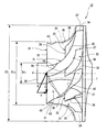
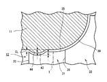
図2に示すように、コンプレッサインペラ12は略円錐台状のハブ部30を備えている。ハブ部30の外周径は、軸心P方向において空気入口部15側からベアリングハウジング22へ向かう所定の位置までは一定であり、所定の位置からベアリングハウジング22へ近づくにつれて大きくなっている。ハブ部30には、図3に示すように周方向に設けた複数のインペラ翼を備えている。本実施形態のインペラ翼は、空気入口部15から空気出口部16まで延在する複数の長翼31と、長翼31よりも延在長さが短い複数の短翼32とを備えている。長翼31と短翼32とは周方向において交互に配置されている。長翼31および短翼32は三次元的に湾曲した板状に形成されている。長翼31は第1インペラ翼に相当し、短翼32は第2インペラ翼に相当する。
As shown in FIG. 2, the
長翼31は、空気入口部15に対向する前縁(リーディングエッジ)33と空気出口部16に対向する後縁(トレーディングエッジ)34を有する。長翼31は、前縁33と後縁34とを結び、湾曲線として描かれる外周縁(インペラシュラウドライン)35を有している。外周縁35の前縁33側はほぼ直線であり、後縁34へ向けて円弧を描くように後縁34に達している。長翼31の後縁34は径方向においてハブ部30の外周縁に位置する。
The
短翼32は、空気入口部15に対向する前縁(リーディングエッジ)36と空気出口部16に対向する後縁(トレーディングエッジ)37を有する。短翼32は、前縁36と後縁37とを結び、湾曲線として描かれる外周縁(インペラシュラウドライン)38を有している。短翼32の前縁36は、回転軸19の軸心P方向において長翼31の前縁33よりも空気入口部15から離れて位置する。短翼32の後縁37は径方向においてハブ部30の外周縁に位置する。従って、短翼32の外周縁38の長さは長翼31の外周縁35の長さより短い。外周縁38は前縁36から円弧を描くように後縁37に達している。
The
図3では、ハブ部30における空気入口部15側の最小外周径D1hとし、空気入口部15におけるコンプレッサハウジング11の内周径D1sとしている。また、ハブ部30における空気出口部16側の最大外周径D2とする。長翼31の前縁36付近の流路断面積Aは内周径D1sおよび最小外周径D1hに基づいて式1から得られる。πは円周率である。
A=π・(D1s/2−D1h/2)2 ・・・(式1)
In FIG. 3, the minimum outer peripheral diameter D1h on the
A = π · (D1s / 2−D1h / 2) 2 (Formula 1)
コンプレッサインペラ12における空気入口部15側では、ハブ部30の周方向において互いに長翼31が隣り合う。図3に示すように、コンプレッサハウジング11および互いに隣り合う一対の長翼31によりインペラスロート部Tが区画される。インペラスロート部Tは長翼31の間の空気流路において流路断面積が急縮小する領域を指す。インペラスロート部Tはコンプレッサインペラ12の周方向において長翼31の数に応じて存在する。本実施形態では、インペラスロート部Tにおけるハブ部30の外周径は、ハブ部30の空気入口部15側の外周径(D1h)と等しい。ハブ部30の外周径は、インペラスロート部Tから軸心P方向におけるベアリングハウジング22へ向かうほど大きくなる(図2を参照)。
On the
図2に示すように、コンプレッサハウジング11は、長翼31の外周縁35および短翼32の外周縁38に対向するシュラウド壁39を備えている。シュラウド壁39は外周縁35、38に倣うように形成されている。従って、インペラスロート部Tは、一対の長翼31とシュラウド壁39とにより区画されている。空気入口部15におけるコンプレッサインペラ12とシュラウド壁39との間には入口クリアランスCLが設定されている。
As shown in FIG. 2, the
図4は長翼31と短翼32とインペラスロート部Tとを模式的に展開して示す図である。図4では、コンプレッサインペラ12へ流入する空気の絶対速度をCとし、コンプレッサインペラ12の周速をUとしている。長翼31へ流入する空気の相対速度は流入相対速度Wである。長翼31の前縁33における中心線(キャンバーライン)Lと流入相対速度Wとが成す角度は迎角αである。軸心Pと中心線Lとが成す角度は翼角βである。図4ではインペラスロート部Tを一点鎖線にて示す。
FIG. 4 is a diagram schematically showing the
図4では、インペラスロート部Tを区画する一対の長翼31のうち、一方の長翼31を長翼31Aとし、他方の長翼31を長翼31Bとしている。この場合、インペラスロート部Tは他方の長翼31Bの前縁33を基準に規定される。長翼31Aは長翼31Bよりもコンプレッサインペラ12の回転方向前方に位置する。つまり、長翼31Aはインペラスロート部Tよりもコンプレッサインペラ12の回転方向前方に位置する。長翼31Aは、インペラスロート部Tから空気入口部15側へ延在する入口側翼部41と、インペラスロート部Tより空気出口部16側へ延在する出口側翼部42と、を有する。他方の長翼31Bは、インペラスロート部Tよりもコンプレッサインペラ12の回転方向後方に位置する。
In FIG. 4, of the pair of
図4に示す長翼31Bを回転方向前方の長翼31として見る場合には、長翼31Bの回転方向後方の長翼31Cとの間にインペラスロート部Tが存在する。従って、長翼31Bと長翼31Cとの間のインペラスロート部Tから見ると、長翼31Bが一方の長翼に相当し、長翼31Cが他方の長翼に相当する。つまり、インペラスロート部Tを基準として回転方向前方の長翼31は一方の長翼に相当し、インペラスロート部Tの回転方向後方の長翼31が他方の長翼に相当する。この場合、インペラスロート部Tは他方の長翼31Cの前縁33を基準に規定される。
When the
本実施形態では、一方の長翼31Bの入口側翼部41には、外周縁35の一部が径方向内側へ凹むように円弧状の凹部43が形成されている。凹部43は、入口側翼部41における低速時の空気層の剥離を抑制するために設けられている。因みに、長翼31Aの入口側翼部41は、長翼31Aにおいて低速時の空気層の剥離が最も生じやすい部位である。コンプレッサインペラ12における全ての長翼31に凹部43が形成されている。図5に示すように、前縁33の入口クリアランスCLを規定する外周縁35から凹部43の径方向において最も深い点までの距離を凹み量Qとしている。本実施形態では、凹み量Qと入口クリアランスCLとの関係は、式2を満たすように設定されている。
0<Q/CL<3・・・(式2)
In the present embodiment, an
0 <Q / CL <3 (Formula 2)
一方、シュラウド壁39は、長翼31の凹部43と対向する位置に、凹部43に対応する断面形状の環状の凸部44が形成されている。凸部44は、シュラウド壁39の空気入口部15寄りにて周方向にわたって形成されている。シュラウド壁39から凸部44の径方向において最も突出している点までの距離を突出量Rとしている。本実施形態では凹み量Qと突出量Rは等しい(Q=R)。従って、凹部43における外周縁35とシュラウド壁39における凸部44との間のクリアランスは一定である。なお、シュラウド壁39に凸部44が設けられていることから、例えば、コンプレッサハウジング11を軸心Pに沿って2分割可能な構成とすれば、コンプレッサハウジング11の組み付けが可能となる。
On the other hand, the
凹部43および凸部44に対応する位置での流路断面積をAtとすると、流路断面積Atは、式3により求められる。πは円周率である。
At=π・{(D1s/2−Q)−D1h/2}2 ・・・(式3)
従って、流路断面積Atは、長翼31の前縁36付近の流路断面積Aよりも減少している。
When the channel cross-sectional area at the position corresponding to the
At = π · {(D1s / 2−Q) −D1h / 2} 2 (Formula 3)
Therefore, the channel cross-sectional area At is smaller than the channel cross-sectional area A in the vicinity of the leading
次に、本実施形態のターボチャージャ10の作用について説明する。ターボチャージャ10が一定の回転数で回転されるとき、コンプレッサインペラ12には空気が取り込まれる。このとき、コンプレッサインペラ12を通過する空気流量は一定となる。空気流量をGaとすると、空気流量Gaは、式4により求められる。ρは空気の密度である。
Ga=ρ・C・A ・・・(式4)
空気流量Gaは流路断面積Aと空気の絶対速度Cに比例することが知られている。一対の長翼31の間を通過する空気流についてみると、一方の長翼31の入口側翼部41の翼面は、他方の長翼31の空気入口部15側の翼面と比べると低圧となる。空気流量Gaが一定であって空気の絶対速度Cが小さくなると、迎角αが大きくなり、入口側翼部41において空気層の剥離が発生し易くなる。
Next, the operation of the
Ga = ρ · C · A (Formula 4)
It is known that the air flow rate Ga is proportional to the flow path cross-sectional area A and the absolute velocity C of air. Looking at the air flow passing between the pair of
本実施形態では、凹部43および凸部44を設けたことにより、コンプレッサインペラ12における空気流路の途中の流路断面積Atは流路断面積Aよりも減少されている。このため、コンプレッサインペラ12を通過する空気流量が一定のとき、コンプレッサインペラ12における凹部43に対応する入口側翼部41を通過する空気の絶対速度Cは増大する。入口側翼部41を通過する空気の増速により、仰角αが小さくなるため、入口側翼部41における低速時の空気層の剥離が抑制される。入口側翼部41を通過した空気はインペラスロート部Tを通り、出口側翼部42を通過して空気出口部16から噴出される。
In the present embodiment, by providing the
凹み量Qと入口クリアランスCLとの関係では、式2を満たすことが好ましく、この場合、高速時のコンプレッサ能力を低下させることなく、低速時における入口側翼部41からの空気層の剥離が確実に抑制され、インペラ効率が改善される。 In the relationship between the dent amount Q and the inlet clearance CL, it is preferable to satisfy Expression 2. In this case, the air layer is reliably separated from the inlet side wing portion 41 at the low speed without lowering the compressor capacity at the high speed. It is suppressed and the impeller efficiency is improved.
本実施形態のターボチャージャ10によれば、以下の作用効果を奏する。
(1)コンプレッサインペラ12の入口側翼部41の凹部43およびシュラウド壁39の凸部44に設けることにより、凹部43および凸部44における流路断面積Atは空気入口部15における流路断面積Aと比較して小さくなる。コンプレッサインペラ12を通過する空気の流量は変化しないが、流路断面積の減少により凹部43および凸部44を通過する空気の速度が増大して、入口側翼部41における空気層の剥離が抑制される。その結果、ターボチャージャ10の高速時のコンプレッサの能力を低下させることなく、低速時における空気層の長翼31からの剥離を抑制することができる。
According to the
(1) By providing in the recessed
(2)凹部43は円弧状の凹部であり、凸部44は円弧状の凹部43に倣って断面円弧状に突出する凸部であるため、コンプレッサインペラ12を通過する空気は凹部43および凸部44を円滑に通過することができる。
(2) Since the
(3)空気入口部15におけるコンプレッサインペラ12とシュラウド壁39との入口クリアランスCLに対する凹部43の凹み量との比は、0より大きく3より小さい。コンプレッサインペラ12の入口側翼部41における空気層の剥離をより抑制することができる。
(3) The ratio of the
(変更例1〜3)
次に、変更例1〜3に係るターボチャージャについて説明する。図6(a)に示す変更例1に係るターボチャージャでは、断面が円弧状の凹部51であるが、凹部51の曲率が前縁33から遠ざかるにつれて曲率が小さくなるように設定されている。また、凸部52は凹部51に倣って径方向内側へ向けて突出している。凸部52の曲率は空気入口部15から遠ざかるにつれて曲率が小さくなっている。従って、凹部51および凸部52の前縁33に近い側に対応する流路を通過する空気の速度が増大する。なお、凹部51の曲率が前縁33から遠ざかるにつれて曲率が大きくなるように設定してもよい。
(Modification Examples 1 to 3)
Next, the turbocharger according to the first to third modifications will be described. In the turbocharger according to the first modification shown in FIG. 6A, the cross section is the
図6(b)に示すターボチャージャでは、凹部53の断面は円弧状に形成されているが、前縁33から直ちに形成されるのではなく、前縁33から離れた位置から形成されている。凸部54は凹部53に倣って径方向内側へ向けて突出している。従って、凹部53および凸部54に対応する流路を通過する空気の速度が増大する。
In the turbocharger shown in FIG. 6B, the cross section of the
図6(c)に示すターボチャージャでは、凹部55の断面が円弧状ではなく複数の直線の組み合わせにより形成されている。また、凸部56は凹部55に倣って径方向内側へ向けて突出している。凹部55および凸部56に対応する流路を通過する空気の速度が増大する。なお、図6(a)〜図6(c)に示す凹部51、53、55および凸部52、54、56は誇張して図示している。
In the turbocharger shown in FIG. 6C, the
なお、上記の実施形態は、本発明の一実施形態を示すものであり、本発明は、上記の実施形態に限定されるものではなく、下記のように発明の趣旨の範囲内で種々の変更が可能である。 The above embodiment shows an embodiment of the present invention, and the present invention is not limited to the above embodiment, and various modifications can be made within the scope of the invention as described below. Is possible.
○ 上記の実施形態(変更例を含む)では、2種類の翼(長翼と短翼)を備えたコンプレッサインペラについて例示したが、この限りではない。例えば、短翼を備えず長翼のみを備えるコンプレッサであってもよい。
○ 上記の実施形態(変更例を含む)では、互いに隣り合う長翼の間にインペラスロート部が存在するとしたが、この限りではない。例えば、長翼より僅かに短い短翼を設け、長翼と短翼との間にインペラスロート部が存在する場合でも、本発明は適用可能である。
○ 上記の実施形態(変更例を含む)では、インペラスロート部より空気入口部側へ延在する入口側翼部の一部に凹部を形成するとしたがこの限りではない。例えば、入口側翼部にわたって凹部を形成してもよく、凹部の軸方向の長さは各種の条件に応じて変更可能である。
○ 上記の実施形態(変更例を含む)では、空気入口部におけるコンプレッサインペラとシュラウド壁との入口クリアランスCLに対する凹部の凹み量Qとの比(Q/CL)は、好ましい条件として0より大きく3より小さいとしたが、この限りではない。入口クリアランスCLに対する凹部の凹み量Qとの比(Q/CL)は、コンプレッサインペラの諸条件によっては3以上であってもよい。
In the above embodiment (including the modified example), the compressor impeller provided with two types of blades (long blade and short blade) is exemplified, but the present invention is not limited to this. For example, a compressor having only long blades without short blades may be used.
In the above embodiment (including the modified example), the impeller throat portion is present between the adjacent long blades. For example, the present invention can be applied even when a short blade slightly shorter than the long blade is provided and an impeller throat portion exists between the long blade and the short blade.
In the above embodiment (including the modified example), the concave portion is formed in a part of the inlet side wing portion that extends from the impeller throat portion to the air inlet portion side, but this is not restrictive. For example, a recess may be formed over the inlet side wing, and the axial length of the recess can be changed according to various conditions.
In the above-described embodiment (including the modified example), the ratio (Q / CL) of the recess depression Q to the inlet clearance CL between the compressor impeller and the shroud wall at the air inlet is larger than 0 as a preferable condition. It is said that it is smaller, but this is not the case. The ratio (Q / CL) of the depression amount Q to the inlet clearance CL may be 3 or more depending on various conditions of the compressor impeller.
10 ターボチャージャ
11 コンプレッサハウジング
12 コンプレッサインペラ
15 空気入口部
16 空気出口部
19 回転軸
30 ハブ部
31 長翼
32 短翼
33 前縁
35 外周縁
39 シュラウド壁
41 入口側翼部
42 出口側翼部
43、51、53、55 凹部
44、52、54、56 凸部
A、At 流路断面積
CL 入口クリアランス
Q 凹み量
R 突出量
T インペラスロート部
W 空気の流入相対速度
U インペラの周速
C 空気の絶対速度
α 迎角
β 翼角
DESCRIPTION OF
Claims (3)
前記コンプレッサハウジング内にて回転可能なコンプレッサインペラと、
前記コンプレッサハウジングに設けられ、前記コンプレッサインペラと対向するシュラウド壁と、を備え、
前記コンプレッサインペラは、
ハブ部と、
前記ハブ部の周方向に設けられ、前記空気入口部から前記空気出口部へ向けて延在する複数の第1インペラ翼と、を備え、
前記ハブ部の周方向に互いに隣り合う一対の前記第1インペラ翼の前記コンプレッサインペラの回転方向前方に位置する一方の第1インペラ翼は、前記一対の第1インペラ翼とシュラウド壁とにより区画されるインペラスロート部から前記空気入口部側へ延在する入口側翼部を有し、
前記入口側翼部は、前記第1インペラ翼の前記シュラウド壁と対向する外周縁から前記コンプレッサインペラの径方向内側に凹む凹部を有し、
前記シュラウド壁は、前記第1インペラ翼の前記凹部と対向する位置に、前記凹部に対応する断面形状の環状の凸部を有することを特徴とする過給機。 A compressor housing with an air inlet and an air outlet;
A compressor impeller rotatable in the compressor housing;
A shroud wall provided on the compressor housing and facing the compressor impeller,
The compressor impeller is
A hub,
A plurality of first impeller blades provided in a circumferential direction of the hub portion and extending from the air inlet portion toward the air outlet portion,
One of the pair of first impeller blades adjacent to each other in the circumferential direction of the hub portion is positioned in front of the compressor impeller in the rotation direction, and is partitioned by the pair of first impeller blades and a shroud wall. An inlet wing extending from the impeller throat part to the air inlet part side,
The inlet side wing portion has a concave portion that is recessed inward in the radial direction of the compressor impeller from an outer peripheral edge facing the shroud wall of the first impeller blade.
The supercharger, wherein the shroud wall has an annular convex portion having a cross-sectional shape corresponding to the concave portion at a position facing the concave portion of the first impeller blade.
Priority Applications (1)
| Application Number | Priority Date | Filing Date | Title |
|---|---|---|---|
| JP2016095186A JP6642258B2 (en) | 2016-05-11 | 2016-05-11 | Supercharger |
Applications Claiming Priority (1)
| Application Number | Priority Date | Filing Date | Title |
|---|---|---|---|
| JP2016095186A JP6642258B2 (en) | 2016-05-11 | 2016-05-11 | Supercharger |
Publications (2)
| Publication Number | Publication Date |
|---|---|
| JP2017203410A true JP2017203410A (en) | 2017-11-16 |
| JP6642258B2 JP6642258B2 (en) | 2020-02-05 |
Family
ID=60322064
Family Applications (1)
| Application Number | Title | Priority Date | Filing Date |
|---|---|---|---|
| JP2016095186A Active JP6642258B2 (en) | 2016-05-11 | 2016-05-11 | Supercharger |
Country Status (1)
| Country | Link |
|---|---|
| JP (1) | JP6642258B2 (en) |
Cited By (1)
| Publication number | Priority date | Publication date | Assignee | Title |
|---|---|---|---|---|
| CN111005770A (en) * | 2019-12-24 | 2020-04-14 | 哈尔滨工程大学 | Centripetal turbine with splitter blades |
-
2016
- 2016-05-11 JP JP2016095186A patent/JP6642258B2/en active Active
Cited By (2)
| Publication number | Priority date | Publication date | Assignee | Title |
|---|---|---|---|---|
| CN111005770A (en) * | 2019-12-24 | 2020-04-14 | 哈尔滨工程大学 | Centripetal turbine with splitter blades |
| CN111005770B (en) * | 2019-12-24 | 2022-06-21 | 哈尔滨工程大学 | Centripetal turbine with splitter blades |
Also Published As
| Publication number | Publication date |
|---|---|
| JP6642258B2 (en) | 2020-02-05 |
Similar Documents
| Publication | Publication Date | Title |
|---|---|---|
| JP4691002B2 (en) | Mixed flow turbine or radial turbine | |
| JP5444836B2 (en) | Centrifugal compressor | |
| JP3927886B2 (en) | Axial flow compressor | |
| JP2008075536A (en) | Centrifugal compressor | |
| JP6017033B2 (en) | Radial inflow axial flow turbine and turbocharger | |
| JP2008075536A5 (en) | ||
| WO2018146753A1 (en) | Centrifugal compressor and turbocharger | |
| WO2011007466A1 (en) | Impeller and rotary machine | |
| JP2011137458A (en) | System and apparatus relating to compressor operation in turbo engine | |
| JP2009197613A (en) | Centrifugal compressor and diffuser vane unit | |
| JP2017203427A (en) | Turbocharger | |
| JP6357830B2 (en) | Compressor impeller, centrifugal compressor, and supercharger | |
| JP6617837B2 (en) | Variable nozzle unit and turbocharger | |
| JP2017193985A (en) | Turbine impeller | |
| JP2009221984A (en) | Centrifugal compressor | |
| JP4918455B2 (en) | Turbocharger | |
| JP5125718B2 (en) | Centrifugal compressor | |
| JP2012002140A (en) | Turbine and supercharger | |
| JP2017203410A (en) | Supercharger | |
| JP2012177355A (en) | Twin scroll type radial flow turbine and supercharger | |
| JP6299833B2 (en) | Turbine and vehicle turbocharger | |
| JP2016061223A (en) | Turbo rotary machine | |
| JP2014234713A (en) | Radial turbine and supercharger | |
| JP2014234803A (en) | Variable displacement turbine and variable displacement supercharger | |
| JPWO2018123045A1 (en) | Turbine and turbocharger |
Legal Events
| Date | Code | Title | Description |
|---|---|---|---|
| A621 | Written request for application examination |
Free format text: JAPANESE INTERMEDIATE CODE: A621 Effective date: 20180802 |
|
| A977 | Report on retrieval |
Free format text: JAPANESE INTERMEDIATE CODE: A971007 Effective date: 20190530 |
|
| A131 | Notification of reasons for refusal |
Free format text: JAPANESE INTERMEDIATE CODE: A131 Effective date: 20190604 |
|
| A521 | Written amendment |
Free format text: JAPANESE INTERMEDIATE CODE: A523 Effective date: 20190719 |
|
| TRDD | Decision of grant or rejection written | ||
| A01 | Written decision to grant a patent or to grant a registration (utility model) |
Free format text: JAPANESE INTERMEDIATE CODE: A01 Effective date: 20191203 |
|
| A61 | First payment of annual fees (during grant procedure) |
Free format text: JAPANESE INTERMEDIATE CODE: A61 Effective date: 20191216 |
|
| R151 | Written notification of patent or utility model registration |
Ref document number: 6642258 Country of ref document: JP Free format text: JAPANESE INTERMEDIATE CODE: R151 |