EP4211382B1 - Kopplungseinrichtung für fluidleitungen - Google Patents
Kopplungseinrichtung für fluidleitungen Download PDFInfo
- Publication number
- EP4211382B1 EP4211382B1 EP21772739.5A EP21772739A EP4211382B1 EP 4211382 B1 EP4211382 B1 EP 4211382B1 EP 21772739 A EP21772739 A EP 21772739A EP 4211382 B1 EP4211382 B1 EP 4211382B1
- Authority
- EP
- European Patent Office
- Prior art keywords
- unit
- closure element
- plug
- receiving unit
- coupling device
- Prior art date
- Legal status (The legal status is an assumption and is not a legal conclusion. Google has not performed a legal analysis and makes no representation as to the accuracy of the status listed.)
- Active
Links
Images


Classifications
-
- F—MECHANICAL ENGINEERING; LIGHTING; HEATING; WEAPONS; BLASTING
- F16—ENGINEERING ELEMENTS AND UNITS; GENERAL MEASURES FOR PRODUCING AND MAINTAINING EFFECTIVE FUNCTIONING OF MACHINES OR INSTALLATIONS; THERMAL INSULATION IN GENERAL
- F16L—PIPES; JOINTS OR FITTINGS FOR PIPES; SUPPORTS FOR PIPES, CABLES OR PROTECTIVE TUBING; MEANS FOR THERMAL INSULATION IN GENERAL
- F16L37/00—Couplings of the quick-acting type
- F16L37/08—Couplings of the quick-acting type in which the connection between abutting or axially overlapping ends is maintained by locking members
- F16L37/12—Couplings of the quick-acting type in which the connection between abutting or axially overlapping ends is maintained by locking members using hooks, pawls, or other movable or insertable locking members
- F16L37/14—Joints secured by inserting between mating surfaces an element, e.g. a piece of wire, a pin, a chain
- F16L37/142—Joints secured by inserting between mating surfaces an element, e.g. a piece of wire, a pin, a chain where the securing element is inserted tangentially
- F16L37/144—Joints secured by inserting between mating surfaces an element, e.g. a piece of wire, a pin, a chain where the securing element is inserted tangentially the securing element being U-shaped
-
- F—MECHANICAL ENGINEERING; LIGHTING; HEATING; WEAPONS; BLASTING
- F16—ENGINEERING ELEMENTS AND UNITS; GENERAL MEASURES FOR PRODUCING AND MAINTAINING EFFECTIVE FUNCTIONING OF MACHINES OR INSTALLATIONS; THERMAL INSULATION IN GENERAL
- F16L—PIPES; JOINTS OR FITTINGS FOR PIPES; SUPPORTS FOR PIPES, CABLES OR PROTECTIVE TUBING; MEANS FOR THERMAL INSULATION IN GENERAL
- F16L37/00—Couplings of the quick-acting type
- F16L37/28—Couplings of the quick-acting type with fluid cut-off means
- F16L37/30—Couplings of the quick-acting type with fluid cut-off means with fluid cut-off means in each of two pipe-end fittings
- F16L37/32—Couplings of the quick-acting type with fluid cut-off means with fluid cut-off means in each of two pipe-end fittings at least one of two lift valves being opened automatically when the coupling is applied
- F16L37/35—Couplings of the quick-acting type with fluid cut-off means with fluid cut-off means in each of two pipe-end fittings at least one of two lift valves being opened automatically when the coupling is applied at least one of the valves having an axial bore communicating with lateral apertures
-
- F—MECHANICAL ENGINEERING; LIGHTING; HEATING; WEAPONS; BLASTING
- F16—ENGINEERING ELEMENTS AND UNITS; GENERAL MEASURES FOR PRODUCING AND MAINTAINING EFFECTIVE FUNCTIONING OF MACHINES OR INSTALLATIONS; THERMAL INSULATION IN GENERAL
- F16L—PIPES; JOINTS OR FITTINGS FOR PIPES; SUPPORTS FOR PIPES, CABLES OR PROTECTIVE TUBING; MEANS FOR THERMAL INSULATION IN GENERAL
- F16L37/00—Couplings of the quick-acting type
- F16L37/28—Couplings of the quick-acting type with fluid cut-off means
- F16L37/38—Couplings of the quick-acting type with fluid cut-off means with fluid cut-off means in only one of two pipe-end fittings
- F16L37/40—Couplings of the quick-acting type with fluid cut-off means with fluid cut-off means in only one of two pipe-end fittings with a lift valve being opened automatically when the coupling is applied
- F16L37/42—Couplings of the quick-acting type with fluid cut-off means with fluid cut-off means in only one of two pipe-end fittings with a lift valve being opened automatically when the coupling is applied the valve having an axial bore communicating with lateral apertures
Definitions
- the present invention relates to a coupling device for fluid lines, which comprises a receiving unit and a plug-in unit.
- Coupling devices designed to couple two fluid lines to each other are known from the prior art.
- this usually results in the problem that fluid dynamics at the coupling point are significantly worse than those in the rest of the fluid line, as the components of the coupling device can cause turbulence and dead zones in the fluid being conducted.
- a spring element can cause severe disruption of the fluid flow in the area of the coupling device.
- the presence of dead zones can lead to an accumulation of fluid within the coupling device, which can then escape uncontrollably when the coupling device is disconnected. This can lead to environmental contamination or, for example, in the case of hazardous substances transported within the fluid line, to harm the environment and/or the operator of the coupling device.
- the inventive arrangement of the coupling device or the receiving unit enables the spring element to be arranged separately from the fluid flowing through the receiving unit, at least in the release position of the associated closure element, in which passage of fluid through the receiving unit is possible, thereby achieving improved fluid flow through the receiving unit. Furthermore, this can prevent fluid from accumulating in the area in which the spring is arranged and escaping from the receiving unit in an uncontrolled manner when the coupling device, i.e. the receiving unit, is released from a complementary plug-in unit.
- the closure element can be constructed in several parts, in particular in two parts, wherein the individual components of the closure element can be connected to one another, for example, via matching internal and external threads, in order to simplify assembly of the closure element.
- the receiving unit can in particular be designed to be connectable to a, in particular standardized, standard plug-in unit.
- the receiving unit or the entire higher-level coupling device is suitable for connecting both smooth pipes and corrugated pipes It is advisable for connecting sections of the coupling device, at which the coupling device is to be connected to corresponding fluid lines, to have a connecting piece element provided with a sawtooth profile.
- a connecting piece element provided with a sawtooth profile.
- at least one groove can be provided on such a connecting piece element, in which a sealing element, such as an O-ring, can be received in order to seal against the fluid line.
- the closure element can have a plurality of ribs, in particular at least three ribs, on its outer circumference, which protrude radially outwards from the closure element and can come into contact with a respective section of the surrounding receiving unit at their radially outer end.
- the spring element can be a wave spring.
- a wave spring requires less space while providing the same spring force.
- the spring element can be arranged radially outside the cylindrical portion.
- the cylindrical portion can shield the spring element from the radially inner flow channel on the inner circumference of the spring element.
- the perforations of the partial section can be designed as four window-like openings.
- the perforations are arranged such that, when the closure element has left its closed position, fluid flows through the perforations from radially outside the closure element to radially inside, or vice versa in the case of an opposite flow direction.
- the cylindrical, perforation-free section of the closure element can also be designed such that interact with the receiving unit, for example a projection of the receiving unit, so that essentially all fluid reaching the area of the openings in the closure element is guided through the openings into the interior of the closure element instead of flowing radially past it on the outside.
- the receiving unit can have a housing in which the closure element is received, wherein the housing can have a radially inwardly extending projection which is designed to come into contact with the closure element, in particular a sealing element arranged on the closure element, in the closed position of the closure element.
- the sealing element can be formed separately from the closure element, for example as an O-ring. As already described above, this projection can be designed to come into contact both with the sealing element in the closed position of the closure element and with the cylindrical section of the closure element, in particular in the release position of the closure element.
- the projection can in particular be formed integrally with the housing of the receiving unit.
- the projection can be provided with an inclined flank, so that the projection results in a gradually decreasing cross-section of the interior of the housing in a direction from the release position to the closed position of the closure element.
- a projection can be used to guide and center the closure element, for example, when moving into the closed position.
- the inclined flanks can provide the sealing element with a defined sealing surface to engage, so that sealing by the sealing element can be ensured.
- the inclined flanks can guide the fluid flow from radially outwards through the openings in the closure element to radially inwards, thus improving it.
- the housing of the receiving unit can be designed in multiple parts, in particular in two parts.
- the housing of the receiving unit can be designed in multiple parts when viewed in an axial direction of the movement axis of the closure element between the closed position and the release position.
- the housing of the receiving unit can, for example, comprise a substantially tubular section which has the radially inwardly projecting projection, and further comprise a closing element on which a connecting section, in particular a nozzle element, is formed with the first end of the receiving unit for connection to a fluid line.
- the division of the housing into a tubular section and a closing element can enable the closure element to be inserted into the receiving unit partially from one side and partially from the other side thereof and to be mounted within the receiving unit.
- a first housing part, which comprises the first end, can be fluid-tightly connected to a second housing part, which comprises the second end, in particular using a spin welding process or a laser welding process.
- the above-described closure element can be fluid-tightly connected to the tubular portion at one end thereof.
- At least one protruding web can be arranged on the housing, which is designed to define the release position of the closure element when it bears against the closure element.
- the release position of the closure element can be defined in particular by the closure element bearing against the free end of the at least one web.
- the webs can, for example, be arranged circumferentially around an opening of a fluid flow channel, which is formed radially within the nozzle element, and from there extend towards the tubular section of the housing of the receiving unit.
- the receiving unit according to the invention and the coupling device according to the invention are, of course, equally suitable for an opposite flow direction.
- the coupling device can, in particular, be configured for pressures of a fluid flowing therein of 2 bar to 5 bar.
- the counter-contact surface of the closure element of the receiving unit is designed as a collar projecting radially from the closure element of the receiving unit.
- the radially projecting collar which is formed in particular on an end face of the cylindrical section of the closure element facing the plug-in unit, allows the surface area of the counter-contact surface to be increased, thus preventing, for example, the contact surface of the plug-in unit from sliding off the counter-contact surface.
- the spring element which preloads the closure element of the receiving unit into the closed position, can be supported on the side of the collar opposite the counter-contact surface for contacting the plug-in unit.
- the other end of the spring element of the receiving unit can be attached, for example, to the projection of the housing of the receiving unit, in particular to a flank of the projection extending radially toward the housing of the receiving unit. be supported.
- the plug-in unit can also comprise a closure element which, in a closed position, is configured to fluidically seal the fluid flow channel of the plug-in unit between a second end opposite the first end with respect to a main flow direction along the fluid flow channel and the first end of the plug-in unit, wherein the closure element of the plug-in unit is displaceable between the closed position and a release position, wherein the closure element of the plug-in unit is preloaded into the closed position using a spring element.
- the spring element can be arranged on the side of the closure element of the plug-in unit facing the first end.
- the spring element of the plug-in unit can also be a wave spring.
- a housing of the plug-in unit can also be constructed in several parts, in particular in two parts.
- a substantially tubular section can be fluid-tightly connected at one end face to a closure element, on which a connecting piece for connection to a fluid line is arranged.
- the plug-in unit can have, in particular on the end face of the tubular section of the housing of the plug-in unit opposite the closure element, a projection projecting radially inwards, which, as described above with respect to the receiving unit, can have an oblique flank, via which the closure element of the plug-in unit can be centered and which offers a corresponding contact surface to a sealing element arranged on the closure element of the plug-in unit.
- the locking element of the plug-in unit can be moved in one direction from the second end of the plug-in unit to the first end of the plug-in unit have an increasing diameter.
- the closure element of the plug-in unit can comprise a first, substantially cylindrical section, on the outer circumference of which the sealing element is arranged for sealing against the housing of the plug-in unit.
- the first cylindrical section can be followed by a conical section, over which an outer diameter of the closure element of the plug-in unit increases.
- This can be followed by a second, substantially cylindrical section, the outer diameter of which is larger than that of the first cylindrical section.
- Sector-like openings can be provided in the region of the conical section, so that the second cylindrical section, which is designed as a ring, can be connected to the first cylindrical section only via remaining webs. This means that in the release position of the closure element of the plug-in unit, fluid can flow past the outer circumference of the first cylindrical section of the closure element of the plug-in unit and then flow radially inward through the second cylindrical section via the openings in the conical section.
- This nozzle-like shape of the plug-in unit's closure element can largely reduce turbulence in the fluid flow in the area of the plug-in element, so that a high flow velocity through the plug-in element can be achieved.
- the closure element of the receiving unit has a central bolt which has a free end which is in towards the second end of the receiving unit, and which is designed, upon insertion of the plug-in unit into the receiving unit, in particular with its free end, to bear against a bolt-receiving surface formed on the closure element of the plug-in unit, so that, upon continued insertion of the plug-in unit into the receiving unit, the closure element of the plug-in unit or the closure element of the receiving unit is displaced from its closed position towards the release position.
- the bolt-receiving surface can be formed, in particular, on a free end face of the first cylindrical section of the closure element of the plug-in unit.
- the bolt of the closure element of the receiving unit and/or the bolt receiving surface of the closure element of the plug-in unit can be dimensioned such that the bolt only comes into contact with the bolt receiving surface when the housing of the plug-in unit has come into contact with a sealing device which is arranged on the receiving unit and which is configured to seal between the receiving unit and the plug-in unit, so that fluid can be prevented from escaping from the coupling device to an outside.
- a spring force of the spring element acting on the closure element of the plug-in unit can be lower, in particular significantly lower, than a spring force of the spring element acting on the closure element of the receiving unit, so that, upon insertion of the plug-in unit into the receiving unit, first the closure element of the plug-in unit is displaced from its closed position into its release position and then, upon continuation of the insertion of the plug-in unit into the receiving unit, the closure element of the receiving unit is displaced from its closed position into its release position.
- the fluid flow direction through the Coupling device runs from the receiving unit to the plug-in unit, it must be ensured that a fluid flow through the receiving unit and thus through the coupling device is only permitted when the plug-in unit is already completely open, i.e. the closure element of the plug-in unit is in the release position.
- the coupling device can be secured in its coupled state between the receiving unit and the plug-in unit by means of a securing element to prevent the plug-in unit from becoming detached from the receiving unit.
- the receiving unit and/or the plug-in unit and/or the respective closure element can be made of plastic, in particular of polyamide, advantageously of PA6 GF30.
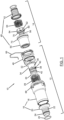
- a coupling device according to the invention according to a first embodiment is generally designated by the reference numeral 10.
- the coupling device 10 comprises a receiving unit 12 and a plug-in unit 14.
- the receiving unit 12 comprises a housing 16, which in turn comprises a substantially tubular section 18 and a closing element 20, wherein the closing element 20 is provided with a (in Figure 1 (shown on the left) end face of the tubular section 18.
- a connecting piece 22 is formed on the end element 20, to which a fluid line, such as a smooth tube, can be coupled.
- a groove 24 is provided on the connecting piece 22 to accommodate a sealing element 26, here an O-ring.
- a wave spring 28 is arranged, which at one end bears against a projection 30 (see Figure 2 ) of the tubular portion 18 of the housing 16 of the receiving unit, which projects radially inwards and is supported at its other end against a collar 32 of a closure element 34.
- the closure element 34 comprises a cylindrical section 36 adjoining the collar 32, which is designed without any openings, to which in turn (in Figure 1 left) is adjoined by a section 40 provided with perforations 38.
- a sealing element receiving section 42 is provided, which is designed to receive a sealing element 44.
- the sealing element 44 is designed to seal the closure element 34 against an inner wall, in particular the projection 30, of the housing 16 of the receiving unit 12.
- a sealing device 46 is shown, which is arranged on an inner side of the housing 16 or the tubular section 18 of the housing 16 of the receiving unit 12 in order to seal the receiving unit 12 with respect to the plug-in unit 14, so that fluid can be prevented from escaping to the outside between the receiving unit 12 and the plug-in unit 14.
- the plug-in unit 14 comprises a housing 48, which comprises a substantially tubular portion 50 and a further closure element 52, wherein the further closure element 52 is generally configured analogously to the closure element 20 of the receiving unit 12.
- a closure element 54 of the plug-in unit 14 is arranged within the housing 48 of the plug-in unit 14 (see also Figure 3 ), which is a first cylindrical portion 56, on which a sealing element 58 is received, a conical portion 60, along which the outer diameter of the closure element 54 of the plug-in unit 14 increases, and a second cylindrical portion 62.
- a securing element 66 can be seen which, in a fully connected state of the receiving unit 12 and the plug-in unit 14, can be releasably inserted in a radial direction to the coupling device 10 through a receiving space 68 of the receiving unit 12 and into a receiving groove 70 of the plug-in unit 14 in order to prevent an axial displacement of the plug-in unit 14 relative to the receiving unit 12 and thus a release of the coupling device 10.
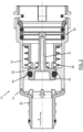
- FIG 2 An enlarged side cross-sectional view of the receiving unit 12 in its assembled state is shown. It can be seen that the wave spring 28 presses the closure element 34 of the receiving unit 12 into the Figure 2 shown closed position. In this closed position of the closure element 34 of the receiving unit 12, the sealing element 44 effects a fluidic seal between the closure element 34 and the projection 30 of the housing 16 of the receiving unit 12. Thus, fluid, which is assumed here to flow in the flow direction indicated by arrow A, is prevented from flowing past the sealing element 44.
- closure element 34 has a central bolt 72 which projects in the direction of that side of the receiving unit 16 over which the Plug-in unit 14 can be inserted into the receiving unit 12.
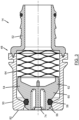
- FIG 3 a side cross-sectional view of the plug-in unit 14 is shown.
- the spring 64 biases the closure element 54 of the plug-in unit 14 towards its closed position, i.e., into a position in which the sealing element 58 is in contact with the tubular portion 50 of the housing 48 of the plug-in unit 14 in such a way that passage of fluid can be prevented.
- a bolt-receiving surface 74 is formed on a free end face of the first cylindrical portion 56 of the closure element 54 of the plug-in unit 14 (see the following detailed description in relation to Figures 4 and 5 ).
- Figure 4 shows the coupling device 10 according to the invention in a partially connected state, namely a state in which the plug-in unit 14 has already been partially inserted into the receiving unit 12 and an outer circumference of the tubular section 50 of the housing 48 of the plug-in unit 14 has at least partially come into sealing contact with the sealing device 46 of the receiving unit 12.
- both the closure element 34 of the receiving unit 12 and the closure element 54 of the plug-in unit 14 are still in their respective closed position, so that the passage of fluid through the coupling device 10 is prevented.
- the central bolt 72 is in Figure 4 has already come into contact with the bolt receiving surface 74 of the plug-in unit 14.
- a spring rate of the wave spring 64 of the plug-in unit 14 is lower than a spring rate of the wave spring 28 of the receiving unit 12, so that upon further insertion of the plug-in unit 14 into the receiving unit 12, after the in Figure 4 shown position, first the wave spring 64 is compressed and thus the closure element 54 of the plug-in unit 14 is moved from its closed position into the release position according to Figure 5 is displaced by the action of the bolt 72.
- the fluid flows through a fluid line (not shown) into the receiving unit 12, that is to say the fluid flow channel formed within the closure element 20 of the housing 16 of the receiving unit 12, from there between the webs 76 radially outwards and radially outwards by the sealing element 44 and the corresponding portion of the closure element 34 of the receiving unit 12 (see the curved arrow A in Figure 5 ), then the fluid flows radially inward via the openings 38 of the closure element 34 of the receiving unit 12 and along the central bolt 72 from the receiving unit 12 into the plug-in unit 14.
- the fluid flows radially outward around the first cylindrical section 56 and the sealing element 58 of the closure element 54 of the plug-in unit 14, then through sector-like openings 78 (see Figure 1 ) through the interior of the wave spring 64 and via a fluid flow channel formed within the end element 52 of the housing 48 of the plug-in unit 14 from the coupling device 10 into a fluid line (again not shown).
- the spring 28, in which in Figure 5 illustrated fully connected state of the coupling device 10, is arranged within a receiving space 80 which is delimited radially inwardly by the cylindrical, perforation-free section 36 of the closure element 34 of the receiving unit 12, radially outwardly by the tubular section 18 of the housing 16 of the receiving unit 12, and in the axial direction at the front and rear by the collar 32 of the closure element 34 of the receiving unit 12 and by the projection 30 of the housing 16 of the receiving unit 12.
- the wave spring 28 can thus be separated from the fluid flow path in the release position of the closure element 34 of the receiving unit 12, so that the discontinuous structure of the wave spring 28 cannot cause any turbulence in the fluid flow that occurs within the receiving unit 12.
- a contact surface 82 (see Figures 3 and 5 ) of the plug-in unit 14, which is shown in the figures for example, on the housing 48 of the plug-in unit 14, can come into contact with a counter-contact surface on the closure element 34 of the receiving unit 12, which in the figures is formed on the side of the collar 32 of the closure element 34 opposite the spring 28, in order to cause a displacement of the closure elements 34 and 54 upon insertion of the plug-in unit 14 into the receiving unit 12.
- FIG. 6 A side cross-sectional view of the receiving unit 112 of the second embodiment is shown in an assembled state, wherein a flow of fluid is blocked in the given illustration.
- the closing element 120 of the receiving unit 112 here has no groove or sealing element at its first end, although these can be provided optionally.
- a sealing device 146 is also provided in the receiving unit 112 (O-rings and spacers not shown here), which seals the receiving unit 112 from the outside relative to the plug-in unit 114.
- the closure element 134 of the receiving unit 112 differs from the closure element 34 of the first exemplary embodiment in particular due to its multi-part construction.
- the closure element 134 comprises internal and external threads arranged parallel to the flow direction A, which are designated together with the reference numeral 135, via which an end section 190 of the closure element 134 and a lower element 133 of the closure element 134 are attached to one another.
- the end section 190 and the lower element 133 can alternatively or additionally be connected to one another, for example by welding, riveting, or caulking, in order to ensure a completely sealed connection between the end section 190 and the lower element 133.
- the end section 190 has webs 194 extending radially outward (see Figure 8 ), the free ends of which are arranged close to or in contact with an inner surface of the housing 116.
- the end section 190 preferably has at least three webs 194, according to the second embodiment shown here, four webs 194. Conical surfaces are arranged at the free ends of the webs 194, which bear against the housing 116 when the closure element 134 is in the closed position. This can prevent the closure element 134 from being displaced beyond the closed position or a sealing element 144 from being damaged or displaced from its receptacle.
- the sealing element 144 which is received between the end section 190 and the lower element 133, effects a fluidic seal between a flow space upstream of the closure element 134 and a flow space downstream of the closure element 134.
- the use of the end section 190 has the further advantage that the webs 194 of the end section 190 secure the O-ring 144 against displacement from its receptacle.
- FIG. 7 Analogous to the Figure 5 described release position of the receiving unit 12 is in Figure 7 the closure element 134 of the receiving unit 112 is shown in the release position, whereby a fluid flow along the flow direction A over the entire length of the receiving unit 112 is enabled.
- no webs 76 are provided in the closing element 120 of the housing 116, since the fluid flows through openings 196 (see Fig. 8 ; in Figure 7 (not shown) of the end section 190.
- the fluid then flows radially outwardly around the sealing element 144 and around an immediately adjacent part of the lower element 133 according to the further course of a tubular section 118 of the receiving unit 112.
- the fluid passes radially inward via openings 138 and then flows past a central bolt 172 within a cylindrical section 136 of the closure element 134. Due to the axial arrangement of the bolt 172, the previously radial flow is converted into an axial flow in such a way that undesired turbulence or stagnation effects are reduced or even avoided.
- the fluid then flows further within a plug-in unit 114 (not shown here but described further below).
- Figure 8 shows a perspective view of the closure element 134, comprising the end section 190 and the lower element 133, as already mentioned above.
- the end section 190 comprises a plate-shaped base section 192 and several, here four, webs 194 projecting radially from the base section 192. Between the individual projecting webs 194, the openings 196 are provided, through which fluid can pass in the release position of the closure element 134.
- Figure 8 the arrangement of the window-like openings 138 of the lower element 133, which are designed to provide a fluidic connection between an exterior and an interior of the closure element 134 to produce.
- FIG. 9 A second embodiment of a coupling device 110 according to the invention is shown in Figure 9 shown in a side cross-sectional view.
- the coupling device 110 has the previously described receiving unit 112 and a plug-in unit 114, in which a closure element 154 is received analogously to the plug-in unit 14.
- the housing 148 of the plug-in unit 114 is here formed in two parts, comprising a tubular section 150 and a further closing element 152, which, analogously to the further closing element 52, can be connected to a fluid line (not shown) and can optionally have sealing elements for this purpose, wherein a fluid outlet (or fluid inlet in the case of the reverse flow direction) of the closing element 152 is arranged at an angle, here at right angles, to the longitudinal extent of the coupling device 110.
- a fluid outlet or fluid inlet in the case of the reverse flow direction
- the tubular section 150 and the further end element 152 are connected to one another in a fluid-tight manner.
- a wave spring 164 is accommodated within the plug-in unit 114, which preloads the closure element 154 of the plug-in unit 114 into its closed position.
- the wave spring 164 is held in a spring receptacle 163, which is formed integrally with the further closure element 152 and projects annularly into its interior.
- a sealing element 158 which is accommodated radially outwardly on the closure element 154 of the plug-in unit 114, initially comes into contact with a tapered contact surface 165, whereby the sealing element 158 is compressed radially inward.
- the closure element 154 is further displaced until a stop surface 167 of the closure element 154 abuts against a counter-stop surface 169 formed on the housing 148 of the plug-in unit 114.
- the contact between the stop surface 167 and the counter-stop surface 169 thus defines the closed position of the closure element 154.
- the sealing element 158 bears against a cylindrical sealing surface 171, wherein the elastic restoring force of the sealing element 158, which acts essentially orthogonally to the sealing surface 171, supports the sealing effect.
- a cylindrical sealing surface can of course be provided analogously on the receiving unit, which interacts with the sealing element 144.
- connection process of the coupling device 110 will now be described in more detail below.
- a contact surface 151 of the closure element 134 of the receiving unit 112 first contacts a counter-contact surface 153 of the closure element 154 of the plug-in unit 114.
- at least one of the two closure elements 134, 154 is displaced from its closed position towards its release position.
- the spring force of the wave spring 164 is less than the spring force of the wave spring 28, so that the closure element 154 of the plug-in unit 114 is first displaced from its closed position into its release position. Subsequently, a contact surface 132 of the closure element 134 of the receiving unit 112 contacts a counter-contact surface 182 of the housing 148 of the plug-in unit 114, whereby the closure element 134 is also displaced from its closed position toward its release position.
- the wave spring 164 Due to the contact or proximity of the two annular parts, namely spring receptacle 163 and spring receptacle section 173, the wave spring 164 is taken out of contact with the fluid flowing past, so that because the fluid does not come into contact with the wave spring 164, turbulence in this area of the plug-in unit 114 is minimized and no fluid deposits can occur on the wave spring 164.
- the closure element 154 is at its in Figure 9
- the free end shown on the left is guided over a radial thickening within the tubular section 150 of the housing 148.
- a locking device 175 is formed radially outside on the closure element 154 of the plug-in unit 114, which is designed to lock onto the receiving unit 112 in order to prevent undesired decoupling between the receiving unit 112 and the plug-in unit 114.
Landscapes
- Engineering & Computer Science (AREA)
- General Engineering & Computer Science (AREA)
- Mechanical Engineering (AREA)
- Quick-Acting Or Multi-Walled Pipe Joints (AREA)
Description
- Die vorliegende Erfindung betrifft eine Kopplungseinrichtung für Fluidleitungen, welche eine Aufnahmeeinheit und eine Steckeinheit umfasst.
- Es sind aus dem Stand der Technik Kopplungseinrichtungen bekannt, welche dazu eingerichtet sind, zwei Fluidleitungen miteinander zu koppeln. Dabei ergibt sich aber zumeist das Problem, dass an der Koppelstelle, im Vergleich zu der übrigen Fluidleitung, eine deutlich verschlechterte Fluiddynamik auftritt, da es durch die Komponenten der Kopplungseinrichtung zu Verwirbelungen und Totbereichen des zu leitenden Fluids kommen kann. Insbesondere bei der Verwendung von Elementen, welche durch Federelemente in eine bestimmte Stellung vorbelastet sind, kann ein verwendetes Federelement eine starke Störung der Fluidströmung im Bereich der Kopplungseinrichtung hervorrufen.
- Ferner kann es durch das Vorhandensein von Totbereichen zu einer Ansammlung von Fluid darin kommen, welches dann beim Trennen der Kopplungseinrichtung in einer unkontrollierten Weise aus dieser austreten kann. Dies kann zu einer Verschmutzung der Umgebung oder, beispielsweise im Fall von Gefahrenstoffen, welche innerhalb der Fluidleitung befördert werden, zu einer Schädigung der Umgebung und/oder des Bedieners der Kopplungseinrichtung führen.
- Aus dem Dokument
DE 100 13 488 A1 , welches als nächstliegender Stand der Technik erachtet wird, ist eine Kopplungseinrichtung für Fluidleitungen bekannt, deren Aufnahmeeinheit dazu eingerichtet ist, dass deren Fluidströmungskanal vermittels eines Verschlusselements fluidisch abgedichtet oder freigegeben werden kann. Ferner sei auf die DokumenteUS 5 540 250 A ,US 2014/083542 A1 ,US 2017/307123 A1 ,FR 2 166 770 A5 US 2 322 877 A ,WO 2019/190658 A1 undUS 4 700 743 A hingewiesen. - Es ist daher die Aufgabe der vorliegenden Erfindung, eine Kopplungseinrichtung für Fluidleitungen bereitzustellen, deren Strömungseigenschaften verbessert und zugleich entsprechende Totbereiche reduziert sind.
- Diese Aufgabe wird erfindungsgemäß durch eine Kopplungseinrichtung für Fluidleitungen nach Anspruch 1 gelöst.
- Die erfindungsgemäße Anordnung der Kopplungseinrichtung bzw. der Aufnahmeeinheit ermöglicht es, dass das Federelement, zumindest in der Freigabestellung des zugehörigen Verschlusselements, in welcher ein Durchtritt von Fluid durch die Aufnahmeeinheit ermöglicht ist, von dem durch die Aufnahmeeinheit strömenden Fluid getrennt angeordnet ist, wodurch eine verbesserte Fluidströmung durch die Aufnahmeeinheit erreicht werden kann. Ferner kann auf diese Weise verhindert werden, dass sich Fluid in dem Bereich, in welchem die Feder angeordnet ist, ansammelt und bei einem Lösen der Kopplungseinrichtung, das heißt der Aufnahmeeinheit von einer komplementären Steckeinheit, in einer unkontrollierten Weise aus der Aufnahmeeinheit austritt. Das Verschlusselement kann mehrteilig, insbesondere zweiteilig, aufgebaut sein, wobei die einzelnen Bauteile des Verschlusselements beispielsweise über zusammenpassende Innen- und Außengewinde miteinander verbunden werden können, um die Montage des Verschlusselements zu vereinfachen.
- Die Aufnahmeeinheit kann insbesondere dazu eingerichtet sein, mit einer, insbesondere genormten, Standard-Steckeinheit verbindbar zu sein.
- Es sei bereits an dieser Stelle erwähnt, dass die Aufnahmeeinheit bzw. die gesamte übergeordnete Kopplungseinrichtung, natürlich sowohl zur Verbindung von Glattrohren als auch zur Verbindung von Wellrohren eingerichtet sein kann. Dabei bietet es sich an, wenn Verbindungsabschnitte der Kopplungseinrichtung, an welchen die Kopplungseinrichtung mit entsprechenden Fluidleitungen zu verbinden ist, ein mit einem Sägezahnprofil versehenes Stutzenelement aufweist. Zusätzlich kann an einem solchen Stutzenelement wenigstens eine Nut vorgesehen sein, in welcher ein Dichtungselement, wie beispielsweise ein O-Ring, aufgenommen werden kann, um gegenüber der Fluidleitung abzudichten.
- Das Verschlusselement kann für eine bessere Führung in der Aufnahmeeinheit an seinem Außenumfang eine Mehrzahl von Rippen, insbesondere wenigstens drei Rippen, aufweisen, welche von dem Verschlusselement nach radial außen vorstehen und an ihrem radial äußeren Ende mit einem jeweiligen Abschnitt der umgebenden Aufnahmeeinheit in Kontakt treten können.
- Insbesondere kann das Federelement eine Wellenfeder sein. Im Vergleich zu einer Spiralfeder benötigt eine Wellenfeder weniger Bauraum bei gleicher Federkraft.
- Vorteilhafterweise kann das Federelement radial außerhalb des zylindrischen Abschnitts angeordnet sein. Somit kann der zylindrische Abschnitt das Federelement gegenüber dem radial innen liegenden Strömungskanal an dem inneren Umfang des Federelements abschirmen.
- In einer Weiterbildung der vorliegenden Erfindung können die Durchbrechungen des Teilabschnitts als vier fensterartige Öffnungen ausgebildet sein. Insbesondere sind die Durchbrechungen so angeordnet, dass, wenn das Verschlusselement seine Schließstellung verlassen hat, Fluid durch die Durchbrechungen von radial außerhalb des Verschlusselements nach radial innen strömt, bzw. für den Fall einer entgegengesetzten Strömungsrichtung umgekehrt. So kann auch der zylindrische, durchbrechungsfreie Abschnitt des Verschlusselements derart mit der Aufnahmeeinheit, zum Beispiel einem Vorsprung der Aufnahmeeinheit, zusammenwirken, dass im Wesentlichen sämtliches den Bereich der Durchbrechungen des Verschlusselements erreichendes Fluid durch die Durchbrechungen in das Innere des Verschlusselements geleitet wird, anstatt radial außen daran vorbei zu strömen.
- Die Aufnahmeeinheit kann ein Gehäuse aufweisen, in welchem das Verschlusselement aufgenommen ist, wobei das Gehäuse einen sich nach radial innen erstreckenden Vorsprung aufweisen kann, welcher dazu eingerichtet ist, mit dem Verschlusselement, insbesondere einem an dem Verschlusselement angeordneten Dichtungselement, in der Schließstellung des Verschlusselements in Kontakt zu treten. Dabei kann das Dichtungselement von dem Verschlusselement separat, zum Beispiel als O-Ring, ausgebildet sein. Wie bereits voranstehend beschrieben, kann dieser Vorsprung dazu eingerichtet sein, sowohl mit dem Dichtungselement in der Schließstellung des Verschlusselements als auch mit dem zylindrischen Abschnitt des Verschlusselements, insbesondere in der Freigabestellung des Verschlusselements, in Kontakt zu treten. Der Vorsprung kann dabei insbesondere integral mit dem Gehäuse der Aufnahmeeinheit ausgebildet sein.
- Hierfür kann der Vorsprung mit einer schrägen Flanke versehen sein, so dass sich durch den Vorsprung in einer Richtung von der Freigabestellung zu der Schließstellung des Verschlusselements ein allmählich verringernder Querschnitt des Innenraums des Gehäuses ergibt. Durch einen derartigen Vorsprung kann das Verschlusselement zum Beispiel beim Bewegen in die Schließstellung geführt und zentriert werden. Durch die schrägen Flanken kann dem Dichtungselement eine definierte Dichtungsfläche zur Anlage bereitgestellt werden, so dass ein Abdichten durch das Dichtungselement gewährleistet werden kann. Darüber hinaus können die schrägen Flanken die Fluidströmung von radial außen durch die Durchbrechungen des Verschlusselements nach radial innen leiten und somit verbessern.
- Das Gehäuse der Aufnahmeeinheit kann mehrteilig, insbesondere zweiteilig, ausgebildet sein. Insbesondere kann das Gehäuse der Aufnahmeeinheit in einer axialen Richtung der Bewegungsachse des Verschlusselements zwischen der Schließstellung und der Freigabestellung betrachtet mehrteilig ausgebildet sein. Das heißt, das Gehäuse der Aufnahmeeinheit kann zum Beispiel einen im Wesentlichen rohrförmigen Abschnitt umfassen, welcher den radial nach innen vorstehenden Vorsprung aufweist, und ferner ein Abschlusselement umfassen, an welchem ein Verbindungsabschnitt, insbesondere ein Stutzenelement mit dem ersten Ende der Aufnahmeeinheit zur Verbindung mit einer Fluidleitung ausgebildet ist. Die Aufteilung des Gehäuses in rohrförmigen Abschnitt und Abschlusselement kann es ermöglichen, dass das Verschlusselement teilweise von der einen Seite und teilweise von der anderen Seite der Aufnahmeeinheit in diese eingeführt wird und innerhalb der Aufnahmeeinheit montiert wird.
- Es kann ein erster Gehäuseteil, welcher das erste Ende umfasst, mit einem zweiten Gehäuseteil, welcher das zweite Ende umfasst, fluiddicht verbunden sein, insbesondere unter Verwendung eines Rotationsschweißverfahrens oder eines Laserschweißverfahrens. Beispielsweise kann das voranstehend beschriebene Abschlusselement mit dem rohrförmigen Abschnitt an einer Stirnseite davon fluiddicht verbunden sein.
- Vorteilhafterweise kann an dem Gehäuse wenigstens ein vorstehender Steg angeordnet sein, welcher dazu eingerichtet ist, in Anlage gegen das Verschlusselement die Freigabestellung des Verschlusselements zu definieren. Die Freigabestellung des Verschlusselements kann insbesondere durch Anlage des Verschlusselements gegen das freie Ende des wenigstens einen Stegs definiert sein. Die Stege können zum Beispiel umfänglich um eine Mündung eines Fluidströmungskanals, welcher radial innerhalb des Stutzenelements gebildet ist, angeordnet sein und sich von dort in Richtung des röhrenförmigen Abschnitts des Gehäuses der Aufnahmeeinheit erstrecken. Das heißt, in der Freigabestellung des Verschlusselements strömt Fluid, welches aus dem Fluidströmungskanal innerhalb des Stutzenelements austritt, zwischen den Stegen hindurch nach radial außen, umströmt den Abschnitt des Verschlusselements, an welchem das Dichtungselement angeordnet ist, und strömt von dort durch die Durchgangsöffnungen des Verschlusselements nach radial innen und durch das Verschlusselement aus der Aufnahmeeinheit.
- Wie bereits zuvor angedeutet, wird im Rahmen dieser Beschreibung zum Zwecke der Einfachheit maßgeblich auf die Strömungsrichtung von der Aufnahmeeinheit zu der Steckeinheit eingegangen, aber die erfindungsgemäße Aufnahmeeinheit bzw. die erfindungsgemäße Kopplungseinrichtung sind natürlich ebenso für eine entgegengesetzte Strömungsrichtung geeignet. Die Kopplungseinrichtung kann insbesondere für Drücke eines darin strömenden Fluids von 2 bar bis 5 bar eingerichtet sein.
- Erfindungsgemäß ist die Gegenanlagefläche des Verschlusselements der Aufnahmeeinheit als von dem Verschlusselement der Aufnahmeeinheit in radialer Richtung abstehender Kragen ausgebildet. Durch den radial abstehenden Kragen, welcher insbesondere an einer der Steckeinheit zugewandten Stirnfläche des zylindrischen Abschnitts des Verschlusselements ausgebildet ist, kann ein Flächenbereich der Gegenanlagefläche vergrößert werden und somit zum Beispiel ein Abgleiten der Anlagefläche der Steckeinheit an der Gegenanlagefläche vermieden werden. An der Seite des Kragens, welche der Gegenanlagefläche zum Kontaktieren der Steckeinheit entgegengesetzt ist, kann das Federelement abgestützt sein, welches das Verschlusselement der Aufnahmeeinheit in die Schließstellung vorbelastet. Das andere Ende des Federelements der Aufnahmeeinheit kann beispielsweise an dem Vorsprung des Gehäuses der Aufnahmeeinheit, insbesondere einer sich in radialer Richtung zu dem Gehäuse der Aufnahmeeinheit erstreckenden Flanke des Vorsprungs, abgestützt sein.
- In einer Weiterbildung der vorliegenden Erfindung kann auch die Steckeinheit ein Verschlusselement umfassen, welches dazu eingerichtet ist, in einer Schließstellung den Fluidströmungskanal der Steckeinheit zwischen einem, dem ersten Ende in Bezug auf eine Hauptströmungsrichtung entlang des Fluidströmungskanals entgegengesetzten, zweiten Ende und dem ersten Ende der Steckeinheit fluidisch abzudichten, wobei das Verschlusselement der Steckeinheit zwischen der Schließstellung und einer Freigabestellung verlagerbar ist, wobei das Verschlusselement der Steckeinheit unter Verwendung eines Federelements in die Schließstellung vorbelastet ist. Das Federelement kann an der zu dem ersten Ende weisenden Seite des Verschlusselements der Steckeinheit angeordnet sein. Das Federelement der Steckeinheit kann ebenfalls eine Wellenfeder sein.
- Analog zu dem oben beschriebenen mehrteiligen Aufbau des Gehäuses der Aufnahmeeinheit, kann auch ein Gehäuse der Steckeinheit mehrteilig, insbesondere zweiteilig, ausgebildet sein. Auch hier kann ein im Wesentlichen röhrenförmiger Abschnitt an einer Stirnseite fluiddicht mit einem Abschlusselement verbunden sein, an welchem ein Stutzenelement zur Verbindung mit einer Fluidleitung angeordnet ist.
- Die Steckeinheit kann, insbesondere an der dem Abschlusselement entgegengesetzten Stirnseite des röhrenförmigen Abschnitts des Gehäuses der Steckeinheit, einen nach radial innen abstehenden Vorsprung aufweisen, welcher, wie oben in Bezug auf die Aufnahmeeinheit beschrieben, eine schräge Flanke aufweisen kann, über welche das Verschlusselement der Steckeinheit zentriert werden kann und welche einem an dem Verschlusselement der Steckeinheit angeordneten Dichtungselement eine entsprechende Anlagefläche bietet.
- Das Verschlusselement der Steckeinheit kann in einer Richtung von dem zweiten Ende der Steckeinheit zu erstem Ende der Steckeinheit einen ansteigenden Durchmesser aufweisen. Zum Beispiel kann das Verschlusselement der Steckeinheit einen ersten im Wesentlichen zylindrischen Abschnitt umfassen, an dessen äußerem Umfang das Dichtungselement zum Abdichten gegenüber dem Gehäuse der Steckeinheit angeordnet ist. In Strömungsrichtung des Fluids von der Aufnahmeeinheit zu der Steckeinheit betrachtet, kann sich an den ersten zylindrischen Abschnitt ein konischer Abschnitt anschließen, über welchen sich ein Außendurchmesser des Verschlusselements der Steckeinheit vergrößert. Darauf kann ein zweiter im Wesentlichen zylindrischer Abschnitt folgen, dessen Außendurchmesser größer ist als der des ersten zylindrischen Abschnitts. Im Bereich des konischen Abschnitts können sektorartige Durchbrechungen vorgesehen sein, so dass der zweite zylindrische Abschnitt, welcher als Ring ausgebildet ist, mit dem ersten zylindrischen Abschnitt lediglich über verbleibende Stege verbunden sein kann. Das heißt, in der Freigabestellung des Verschlusselements der Steckeinheit, kann Fluid an dem Außenumfang des ersten zylindrischen Abschnitts des Verschlusselements der Steckeinheit vorbeiströmen und dann über die Durchbrechungen des konischen Abschnitts radial innen durch den zweiten zylindrischen Abschnitt strömen.
- Diese düsenartige Form des Verschlusselements der Steckeinheit kann Verwirbelungen in der Fluidströmung im Bereich des Steckelements weitestgehend reduzieren, so dass eine hohe Durchflussgeschwindigkeit durch das Steckelement erreicht werden kann.
- Wenn das Federelement an der freien Stirnfläche des zweiten zylindrischen Abschnitts anliegt, durchströmt das Fluid das Federelement ebenfalls radial innen.
- Erfindungsgemäß weist das Verschlusselement der Aufnahmeeinheit einen zentralen Bolzen auf, welcher ein freies Ende aufweist, welches sich in Richtung des zweiten Endes der Aufnahmeeinheit erstreckt, und welcher dazu eingerichtet ist, auf ein Einführen der Steckeinheit in die Aufnahmeeinheit hin, insbesondere mit seinem freien Ende, gegen eine an dem Verschlusselement der Steckeinheit ausgebildete Bolzen-Aufnahmefläche anzuliegen, so dass, auf ein Fortsetzen des Einführens der Steckeinheit in die Aufnahmeeinheit hin, das Verschlusselement der Steckeinheit bzw. das Verschlusselement der Aufnahmeeinheit aus seiner Schließstellung in Richtung der Freigabestellung verlagert wird. Die Bolzen-Aufnahmefläche kann insbesondere an einer freien Stirnfläche des ersten zylindrischen Abschnitts des Verschlusselements der Steckeinheit ausgebildet sein.
- Dabei können/kann der Bolzen des Verschlusselements der Aufnahmeeinheit und/oder die Bolzen-Aufnahmefläche des Verschlusselements der Steckeinheit derart bemessen sein, dass der Bolzen erst dann mit der Bolzen-Aufnahmefläche in Kontakt tritt, wenn das Gehäuse der Steckeinheit mit einer Dichtungseinrichtung in Kontakt getreten ist, welche an der Aufnahmeeinheit angeordnet ist, und welches eingerichtet ist, zwischen der Aufnahmeeinheit und der Steckeinheit abzudichten, so dass Fluid daran gehindert werden kann, aus der Kopplungseinrichtung zu einer Außenseite hin auszutreten.
- Eine Federkraft des Federelements, welches auf das Verschlusselement der Steckeinheit einwirkt, kann geringer, insbesondere deutlich geringer, sein als eine Federkraft des Federelements, welches auf das Verschlusselement der Aufnahmeeinheit einwirkt, so dass, auf ein Einführen der Steckeinheit in die Aufnahmeeinheit hin, zuerst das Verschlusselement der Steckeinheit aus seiner Schließstellung in seine Freigabestellung verlagert wird und anschließend, auf ein Fortsetzen des Einführens der Steckeinheit in die Aufnahmeeinheit hin, das Verschlusselement der Aufnahmeeinheit aus seiner Schließstellung in seine Freigabestellung verlagert wird. Auf diese Weise kann, unter der Annahme, dass die Fluidströmungsrichtung durch die Kopplungseinrichtung von der Aufnahmeeinheit zu der Steckeinheit verläuft, gewährleistet werden, dass eine Fluidströmung durch die Aufnahmeeinheit und damit durch die Kopplungseinrichtung erst erlaubt wird, wenn die Steckeinheit bereits vollständig geöffnet ist, das heißt sich das Verschlusselement der Steckeinheit in der Freigabestellung befindet.
- Die Kopplungseinrichtung kann zum Beispiel in ihrem gekoppelten Zustand zwischen Aufnahmeeinheit und Steckeinheit über ein Sicherungselement gegenüber einem Lösen der Steckeinheit von der Aufnahmeeinheit gesichert werden.
- Die Aufnahmeeinheit und/oder die Steckeinheit und/oder das jeweilige Verschlusselement kann aus Kunststoff, insbesondere aus Polyamid, vorteilhafterweise aus PA6 GF30, hergestellt sein.
- Im Folgenden wird die vorliegende Erfindung anhand bevorzugter Ausführungsbeispiele in größerem Detail mit Bezug auf die begleitenden Zeichnungen beschrieben werden. Es stellt dar:
- Figur 1
- eine perspektivische Explosionsansicht einer erfindungsgemäßen Kopplungseinrichtung gemäß einem ersten Ausführungsbeispiel;
- Figur 2
- eine Seitenquerschnittsansicht einer Aufnahmeeinheit gemäß dem ersten Ausführungsbeispiel;
- Figur 3
- eine Seitenquerschnittsansicht einer Steckeinheit;
- Figur 4
- eine Seitenquerschnittsansicht einer erfindungsgemäßen Kopplungseinrichtung gemäß dem ersten Ausführungsbeispiel, wobei ein Durchfluss von Fluid versperrt ist;
- Figur 5
- eine Seitenquerschnittsansicht der erfindungsgemäßen Kopplungseinrichtung aus
Figur 4 , wobei ein Durchfluss von Fluid erlaubt ist; - Figur 6
- eine Seitenquerschnittsansicht einer Aufnahmeeinheit gemäß einem zweiten Ausführungsbeispiel, wobei ein Durchfluss von Fluid versperrt ist;
- Figur 7
- eine Seitenquerschnittsansicht der Aufnahmeeinheit aus
Figur 6 , wobei ein Durchfluss von Fluid erlaubt ist; - Figur 8
- eine perspektivische Ansicht eines Verschlusselements des Ausführungsbeispiels aus
Figuren 6 und7 ; und - Figur 9
- eine Seitenquerschnittsansicht einer erfindungsgemäßen Kopplungseinrichtung, basierend auf der Aufnahmeeinheit des zweiten Ausführungsbeispiels sowie einer zu der Aufnahmeeinheit passenden Steckeinheit.
- In
Figur 1 ist eine erfindungsgemäße Kopplungseinrichtung gemäß einem ersten Ausführungsbeispiel allgemein mit dem Bezugszeichen 10 bezeichnet. Die Kopplungseinrichtung 10 umfasst eine Aufnahmeeinheit 12 und eine Steckeinheit 14. Die Aufnahmeeinheit 12 umfasst ein Gehäuse 16, welches wiederum einen im Wesentlichen röhrenförmigen Abschnitt 18 und ein Abschlusselement 20 umfasst, wobei das Abschlusselement 20 mit einer (inFigur 1 links dargestellten) Stirnfläche des röhrenförmigen Abschnitts 18 verbunden werden kann. An dem Abschlusselement 20 ist im ersten Ausführungsbeispiel ein Stutzenelement 22 ausgebildet, mit welchem eine Fluidleitung, wie beispielsweise ein Glattrohr, gekoppelt werden kann. An dem Stutzenelement 22 ist eine Nut 24 vorgesehen, um ein Dichtungselement 26, hier einen O-Ring, aufzunehmen. - Innerhalb des Gehäuses 16 der Aufnahmeeinheit 12 ist eine Wellenfeder 28 angeordnet, welche an ihrem einen Ende gegen einen Vorsprung 30 (siehe
Figur 2 ) des röhrenförmigen Abschnitts 18 des Gehäuses 16 der Aufnahmeeinheit, welcher nach radial innen vorsteht, und an ihrem anderen Ende gegen einen Kragen 32 eines Verschlusselements 34 abgestützt ist. - Das Verschlusselement 34 umfasst einen sich an den Kragen 32 anschließenden zylindrischen Abschnitt 36, welcher durchbrechungsfrei ausgebildet ist, an welchen sich wiederum (in
Figur 1 links) ein mit Durchbrechungen 38 versehener Abschnitt 40 anschließt. An derjenigen Seite des durchbrochenen Abschnitts 40 des Verschlusselements 34, welche dem zylindrischen Abschnitt 36 entgegengesetzt ist, ist ein Dichtungselement-Aufnahmeabschnitt 42 vorgesehen, welcher dazu eingerichtet ist, ein Dichtungselement 44 aufzunehmen. Das Dichtungselement 44 ist dazu eingerichtet, das Verschlusselement 34 gegenüber einer Innenwandung, insbesondere dem Vorsprung 30, des Gehäuses 16 der Aufnahmeeinheit 12 abzudichten. - In
Figur 1 ist rechts von dem Verschlusselement 34 der Aufnahmeeinheit 12 eine Dichtungseinrichtung 46 dargestellt, welche an einer Innenseite des Gehäuses 16 bzw. des röhrenförmigen Abschnitts 18 des Gehäuses 16 der Aufnahmeeinheit 12 angeordnet ist, um die Aufnahmeeinheit 12 gegenüber der Steckeinheit 14 abzudichten, so dass Fluid daran gehindert werden kann, zwischen der Aufnahmeeinheit 12 und der Steckeinheit 14 nach außen zu treten. - Die Steckeinheit 14 umfasst ein Gehäuse 48, welches einen im Wesentlichen röhrenförmigen Abschnitt 50 und ein weiteres Abschlusselement 52 umfasst, wobei das weitere Abschlusselement 52 generell analog zu dem Abschlusselement 20 der Aufnahmeeinheit 12 ausgebildet ist. Innerhalb des Gehäuses 48 der Steckeinheit 14 ist ein Verschlusselement 54 der Steckeinheit 14 angeordnet (siehe auch
Figur 3 ), welches einen ersten zylindrischen Abschnitt 56, an welchem ein Dichtungselement 58 aufgenommen ist, einen konischen Abschnitt 60, entlang welchem sich der Außendurchmesser des Verschlusselements 54 der Steckeinheit 14 vergrößert, und einen zweiten zylindrischen Abschnitt 62 umfasst. Das freie Ende (das inFigur 1 rechts dargestellte Ende) des zweiten zylindrischen Abschnitts 62 des Verschlusselements 54 der Steckeinheit 14 steht mit einer Wellenfeder 64 der Steckeinheit 14 in Kontakt, welche, unter Abstützung gegen das weiteren Abschlusselement 52 der Steckeinheit 14, das Verschlusselement 54 (inFigur 1 nach links) vorbelastet. - In
Figur 1 ist ferner ein Sicherungselement 66 zu sehen, welches, in einem vollständig verbundenen Zustand der Aufnahmeeinheit 12 und der Steckeinheit 14, in einer radialen Richtung zu der Kopplungseinrichtung 10 durch einen Aufnahmeraum 68 der Aufnahmeeinheit 12 und in eine Aufnahmenut 70 der Steckeinheit 14 lösbar eingeführt werden kann, um eine axiale Verlagerung der Steckeinheit 14 relativ zu der Aufnahmeeinheit 12 und damit ein Lösen der Kopplungseinrichtung 10 zu verhindern. - In
Figur 2 ist nun eine vergrößerte Seitenquerschnittsansicht der Aufnahmeeinheit 12 in ihrem zusammengebauten Zustand dargestellt. Dabei ist zu erkennen, dass die Wellenfeder 28 das Verschlusselement 34 der Aufnahmeeinheit 12 in die inFigur 2 dargestellte Schließstellung vorbelastet. In dieser Schließstellung des Verschlusselements 34 der Aufnahmeeinheit 12 bewirkt das Dichtungselement 44 eine fluidische Abdichtung zwischen dem Verschlusselement 34 und dem Vorsprung 30 des Gehäuses 16 der Aufnahmeeinheit 12. Somit wird Fluid, von welchem hier angenommen wird, dass es in der durch den Pfeil A angezeigten Strömungsrichtung strömt, daran gehindert, an dem Dichtungselement 44 vorbei zu strömen. - Ferner ist in der Seitenquerschnittsansicht aus
Figur 2 zu erkennen, dass das Verschlusselement 34 einen zentralen Bolzen 72 aufweist, welcher in Richtung derjenigen Seite der Aufnahmeeinheit 16 vorsteht, über welche die Steckeinheit 14 in die Aufnahmeeinheit 12 eingeführt werden kann. - In
Figur 3 ist eine Seitenquerschnittsansicht der Steckeinheit 14 dargestellt. Auch hier spannt die Feder 64 das Verschlusselement 54 der Steckeinheit 14 in Richtung seiner Schließstellung vor, das heißt in eine Stellung, in welcher das Dichtungselement 58 derart mit dem röhrenförmigen Abschnitt 50 des Gehäuses 48 der Steckeinheit 14 in Kontakt steht, dass ein Durchtritt von Fluid verhindert werden kann. An einer freien Stirnfläche des ersten zylindrischen Abschnitts 56 des Verschlusselements 54 der Steckeinheit 14 ist eine Bolzen-Aufnahmefläche 74 ausgebildet (siehe die nachfolgende detaillierte Beschreibung hierzu in Bezug aufFiguren 4 und5 ). -
Figur 4 zeigt die erfindungsgemäße Kopplungseinrichtung 10 in einem teilverbundenen Zustand, nämlich einem Zustand, in welchem die Steckeinheit 14 zwar bereits teilweise in die Aufnahmeeinheit 12 eingeführt worden ist und auch ein äußerer Umfang des röhrenförmigen Abschnitts 50 des Gehäuses 48 der Steckeinheit 14 mit der Dichtungseinrichtung 46 der Aufnahmeeinheit 12 zumindest teilweise in einen abdichtenden Kontakt getreten ist. Jedoch sind in dem teilweise verbundenen Zustand vonFigur 4 sowohl das Verschlusselement 34 der Aufnahmeeinheit 12 als auch das Verschlusselement 54 der Steckeinheit 14 noch in ihrer jeweiligen Schließstellung, so dass ein Durchtritt von Fluid durch die Kopplungseinrichtung 10 unterbunden wird. Der zentrale Bolzen 72 ist inFigur 4 bereits mit der Bolzen-Aufnahmefläche 74 der Steckeinheit 14 in Kontakt getreten. - Wird die Steckeinheit 14 nun weiter in die Aufnahmeeinheit 12 hinein verlagert, so wird am Ende dieses Einführens der vollständig verbundene Zustand gemäß
Figur 5 erreicht. InFigur 5 sind sowohl das Verschlusselement 34 der Aufnahmeeinheit 12 als auch das Verschlusselement 54 der Steckeinheit 14 in ihrer Freigabestellung angeordnet, so dass Fluid in der Fluidströmungsrichtung, welche durch den Pfeil A angezeigt ist, durch die Kopplungseinrichtung 10 strömen kann. - Obwohl nicht gezeigt, soll für die in den Figuren dargestellte Ausführungsform der erfindungsgemäßen Kopplungseinrichtung 10 angenommen werden, dass eine Federrate der Wellenfeder 64 der Steckeinheit 14 geringer ist als eine Federrate der Wellenfeder 28 der Aufnahmeeinheit 12, so dass bei dem weiteren Einführen der Steckeinheit 14 in die Aufnahmeeinheit 12, nach der in
Figur 4 gezeigten Stellung, zunächst die Wellenfeder 64 komprimiert wird und somit das Verschlusselement 54 der Steckeinheit 14 aus seiner Schließstellung in die Freigabestellung gemäßFigur 5 durch die Wirkung des Bolzens 72 verlagert wird. Hat die Wellenfeder 64 ihre maximale Kompression erreicht oder liegt das Verschlusselement 54 der Steckeinheit 14 gegen einen entsprechenden Anschlag an, so verlagert das weitere Einführen der Steckeinheit 14 in die Aufnahmeeinheit 12 das Verschlusselement 34 der Aufnahmeeinheit 12 aus seiner Schließstellung in die Freigabestellung. Erst zu diesem Zeitpunkt wird dem Fluid erlaubt, an dem Dichtungselement 44, welches an dem Verschlusselement 34 der Aufnahmeeinheit 12 angeordnet ist, vorbei und in die Steckeinheit 14 zu strömen. - In seiner Freigabestellung liegt das Verschlusselement 34 der Aufnahmeeinheit 12 gemäß dem ersten Ausführungsbeispiel gegen Stege 76 an, welche von dem Abschlusselement 20 des Gehäuses 16 der Aufnahmeeinheit 12 vorstehen. Durch den Kontakt zwischen dem Verschlusselement 34 der Aufnahmeeinheit 12 und den Stegen 76 wird die Freigabestellung definiert.
- Mit Bezug auf die in
Figur 5 dargestellte Stellung der Kopplungseinrichtung 10 strömt das Fluid durch eine nicht dargestellte Fluidleitung in die Aufnahmeeinheit 12, das heißt den innerhalb des Abschlusselements 20 des Gehäuses 16 der Aufnahmeeinheit 12 ausgebildeten Fluidströmungskanal, von dort zwischen den Stegen 76 nach radial außen und radial außen um das Dichtungselement 44 und den entsprechenden Abschnitt des Verschlusselements 34 der Aufnahmeeinheit 12 herum (siehe den gekrümmten Pfeil A inFigur 5 ), dann strömt das Fluid über die Durchbrechungen 38 des Verschlusselements 34 der Aufnahmeeinheit 12 nach radial innen und entlang des zentralen Bolzens 72 von der Aufnahmeeinheit 12 in die Steckeinheit 14. In der Steckeinheit 14 strömt das Fluid radial außen um den ersten zylindrischen Abschnitt 56 und das Dichtungselement 58 des Verschlusselements 54 der Steckeinheit 14 herum, dann durch sektorartige Durchbrechungen 78 (sieheFigur 1 ) durch das Innere der Wellenfeder 64 und über einen innerhalb des Abschlusselements 52 des Gehäuses 48 der Steckeinheit 14 ausgebildeten Fluidströmungskanal aus der Kopplungseinrichtung 10 in eine (wiederum nicht dargestellte) Fluidleitung. - Wie insbesondere der
Figur 5 zu entnehmen ist, ist die Feder 28, in dem inFigur 5 dargestellten vollständig verbundenen Zustand der Kopplungseinrichtung 10, innerhalb eines Aufnahmeraums 80 angeordnet, welcher radial innen durch den zylindrischen, durchbrechungsfreien Abschnitt 36 des Verschlusselements 34 der Aufnahmeeinheit 12, radial außen durch den röhrenförmigen Abschnitt 18 des Gehäuses 16 der Aufnahmeeinheit 12 und in axialer Richtung vorne und hinten von dem Kragen 32 des Verschlusselements 34 der Aufnahmeeinheit 12 und von dem Vorsprung 30 des Gehäuses 16 der Aufnahmeeinheit 12 begrenzt ist. Die Wellenfeder 28 kann somit in der Freigabestellung des Verschlusselements 34 der Aufnahmeeinheit 12 von dem Fluidströmungspfad abgetrennt werden, so dass die unstetige Struktur der Wellenfeder 28 keine Verwirbelungen in der Fluidströmung hervorrufen kann, welche innerhalb der Aufnahmeeinheit 12 auftritt. - Nachzutragen sei noch, dass alternativ oder zusätzlich zu dem Kontaktieren des Bolzens 72 und der Bolzen-Aufnahmefläche 74 auch eine Anlagefläche 82 (siehe
Figuren 3 und5 ) der Steckeinheit 14, welche in den Figuren beispielhaft an dem Gehäuse 48 der Steckeinheit 14 ausgebildet ist, mit einer Gegenanlagefläche an dem Verschlusselement 34 der Aufnahmeeinheit 12, welche in den Figuren an der der Feder 28 entgegengesetzten Seite des Kragens 32 des Verschlusselements 34 gebildet ist, in Kontakt treten kann, um, auf ein Einführen der Steckeinheit 14 in die Aufnahmeeinheit 12 hin, eine Verlagerung der Verschlusselemente 34 und 54 hervorzurufen. - Im Folgenden wird unter Bezugnahme auf
Figur 6 ein zweites Ausführungsbeispiel einer erfindungsgemäßen Aufnahmeeinheit 112 beschrieben, welche eine Abwandlung der zuvor beschriebenen Aufnahmeeinheit 12 ist, so dass im weiteren Verlauf nur auf die Unterschiede zum ersten Ausführungsbeispiel näher eingegangen wird und in Bezug auf alle anderen Merkmale und Funktionen auf das erste Ausführungsbeispiel verwiesen wird. Demgemäß können sämtliche Merkmale, Effekte und Vorteile, welche in Bezug auf die erste Ausführungsform der Aufnahmeeinheit 12 (bzw. der zugehörigen Kopplungseinrichtung 10) offenbart sind, gleichermaßen auf die zweite Ausführungsform der Aufnahmeeinheit 112 (bzw. der zugehörigen Kopplungseinrichtung 110) anwendbar sein und umgekehrt. - In
Figur 6 ist eine Seitenquerschnittsansicht der Aufnahmeeinheit 112 des zweiten Ausführungsbeispiels in einem zusammengebauten Zustand dargestellt, wobei ein Durchfluss von Fluid in der gegebenen Darstellung versperrt ist. Das Abschlusselement 120 der Aufnahmeeinheit 112 weist hier im Vergleich zu der Aufnahmeeinheit 12 des ersten Ausführungsbeispiels an dessen erstem Ende keine Nut und kein Dichtungselement auf, welche jedoch optional vorgesehen sein können. Analog zu der Dichtungseinrichtung 46 des ersten Ausführungsbeispiels ist auch in der Aufnahmeeinheit 112 eine Dichtungseinrichtung 146 vorgesehen (O-Ringe und Abstandshalter hier nicht dargestellt), welche die Aufnahmeeinheit 112 gegenüber der Steckeinheit 114 nach außen hin abdichtet. - Das Verschlusselement 134 der Aufnahmeeinheit 112 unterscheidet sich von dem Verschlusselement 34 des ersten Ausführungsbeispiels insbesondere durch seinen mehrteiligen Aufbau. Hier umfasst das Verschlusselement 134 parallel zur Strömungsrichtung A angeordnete Innen- und Außengewinde, welche zusammen mit dem Bezugszeichen 135 bezeichnet sind, über welche ein Endabschnitt 190 des Verschlusselements 134 und ein Unterelement 133 des Verschlusselements 134 aneinander angebracht sind. Im Zuge der Montage des Verschlusselements 134 können alternativ oder zusätzlich der Endabschnitt 190 sowie das Unterelement 133 auch miteinander verbunden werden, beispielsweise durch Verschweißen, Vernieten, Verstemmen, um eine vollständig abgedichtete Verbindung zwischen Endabschnitt 190 und Unterelement 133 zu gewährleisten. Der Endabschnitt 190 weist sich nach radial außen erstreckenden Stege 194 auf (s.
Figur 8 ), deren freien Enden nahe zu einer inneren Oberfläche des Gehäuses 116 angeordnet sind oder diese kontaktieren. Bevorzugt weist der Endabschnitt 190 wenigstens drei Stege 194, gemäß der hier dargestellten zweiten Ausführungsform vier Stege 194, auf. An den freien Enden der Stege 194 sind konische Flächen angeordnet, welche in der Schließstellung des Verschlusselements 134 an dem Gehäuse 116 anliegen. Hierdurch kann vermieden werden, dass das Verschlusselement 134 über die Schließstellung hinaus verlagert werden kann bzw. ein Dichtungselement 144 beschädigt oder aus seiner Aufnahme heraus verlagert wird. - In der in
Figur 6 dargestellten Schließstellung des Verschlusselements 134 bewirkt das Dichtungselement 144, welches zwischen dem Endabschnitt 190 sowie dem Unterelement 133 aufgenommen ist, eine fluidische Abdichtung zwischen einem Strömungsraum stromaufwärts des Verschlusselements 134 und einem Strömungsraum stromabwärts des Verschlusselements 134. Die Verwendung des Endabschnitts 190 hat den weiteren Vorteil, dass die Stege 194 des Endabschnitts 190 den O-Ring 144 gegen eine Verlagerung aus seiner Aufnahme sichern. - Analog zu der in
Figur 5 beschriebenen Freigabestellung der Aufnahmeeinheit 12 wird inFigur 7 das Verschlusselement 134 der Aufnahmeeinheit 112 in der Freigabestellung dargestellt, wodurch eine Fluidströmung entlang der Strömungsrichtung A über den gesamten Verlauf der Aufnahmeeinheit 112 ermöglicht wird. Im Gegensatz zu dem ersten Ausführungsbeispiel sind in dem Abschlusselement 120 des Gehäuses 116 keine Stege 76 vorgesehen, da das Fluid durch Öffnungen 196 (s.Fig. 8 ; inFigur 7 nicht dargestellt) des Endabschnitts 190 geleitet wird. Anschließend strömt das Fluid gemäß dem weiteren Verlauf eines röhrenförmigen Abschnitts 118 der Aufnahmeeinheit 112 radial außen um das Dichtungselement 144 sowie um einen unmittelbar angrenzenden Teil des Unterelements 133 herum. Über Durchbrechungen 138 gelangt das Fluid nach radial innen und strömt anschließend innerhalb eines zylindrischen Abschnitts 136 des Verschlusselements 134 an einem zentralen Bolzen 172 vorbei. Durch die axiale Anordnung des Bolzens 172 wird die zuvor radial verlaufende Strömung derart in eine axial verlaufende Strömung überführt, dass ungewünschte Verwirbelungen oder Staueffekte reduziert oder sogar vermieden werden. Der weitere Verlauf des Fluids erfolgt innerhalb einer hier nicht dargestellten, weiter unten beschriebenen Steckeinheit 114. -
Figur 8 zeigt eine perspektivische Ansicht des Verschlusselements 134, umfassend den Endabschnitt 190 sowie das Unterelement 133, wie bereits weiter oben erwähnt. Dabei wird ersichtlich, dass der Endabschnitt 190 einen tellerförmigen Basisabschnitt 192 und mehrere, hier vier, von dem Basisabschnitt 192 radial abstehende Stege 194 umfasst. Zwischen den einzelnen abstehenden Stegen 194 sind die Durchbrechungen 196 vorgesehen, durch welche Fluid in der Freigabestellung des Verschlusselements 134 passieren kann. Ferner geht ausFigur 8 die Anordnung der fensterartigen Durchbrechungen 138 des Unterelements 133 hervor, welche dazu eingerichtet sind, eine fluidische Verbindung zwischen einem Äußeren und einem Inneren des Verschlusselements 134 herzustellen. - Ein zweites Ausführungsbeispiel einer erfindungsgemäßen Kopplungseinrichtung 110 wird in
Figur 9 in einer Seitenquerschnittsansicht dargestellt. Im Unterschied zu der Kopplungseinrichtung 10 des ersten Ausführungsbeispiels weist die Kopplungseinrichtung 110 die zuvor beschriebene Aufnahmeeinheit 112 sowie eine Steckeinheit 114 auf, in welcher analog zu der Steckeinheit 14 ein Verschlusselement 154 aufgenommen ist. Das Gehäuse 148 der Steckeinheit 114 ist hier zweiteilig ausgebildet, umfassend einen röhrenförmigen Abschnitt 150 und ein weiteres Abschlusselement 152, das analog zu dem weiteren Abschlusselement 52 mit einer nicht dargestellten Fluidleitung verbunden werden und hierfür optional Dichtungselemente aufweisen kann, wobei ein Fluidausgang (oder Fluideingang bei umgekehrter Strömungsrichtung) des Abschlusselements 152 gewinkelt, hier rechtwinklig, zur Längserstreckung der Kopplungseinrichtung 110 angeordnet ist. Es sei der Vollständigkeit halber erwähnt, dass, obwohl die Steckeinheit 114 inFigur 9 gewinkelt dargestellt ist, dies nicht zwangsweise der Fall sein muss. Der röhrenförmige Abschnitt 150 und das weitere Abschlusselement 152 sind fluiddicht miteinander verbunden. - Innerhalb der Steckeinheit 114 ist eine Wellenfeder 164 aufgenommen, welche das Verschlusselement 154 der Steckeinheit 114 in seine Schließstellung vorbelastet. Die Wellenfeder 164 ist in einer Federaufnahme 163 gehaltert, welche integral mit dem weiteren Abschlusselement 152 ausgebildet ist und in dessen Inneres ringförmig vorsteht. Bei der Verlagerung des Verschlusselements 154 aus seiner Freigabestellung in seine Schließstellung tritt ein Dichtungselement 158, welches radial außen an dem Verschlusselement 154 der Steckeinheit 114 aufgenommen ist, zunächst mit einer sich verjüngenden Anlagefläche 165 in Kontakt, wodurch das Dichtungselement 158 nach radial innen komprimiert wird. Aufgrund der Wirkung der Wellenfeder 164 wird das Verschlusselement 154 solange weiter verlagert, bis eine Anschlagsfläche 167 des Verschlusselements 154 gegen eine Gegenanschlagsfläche 169 anschlägt, welche an dem Gehäuse 148 der Steckeinheit 114 ausgebildet ist. Durch den Kontakt der Anschlagsfläche 167 und der Gegenanschlagsfläche 169 ist somit die Schließstellung des Verschlusselements 154 definiert. In dieser Schließstellung liegt das Dichtungselement 158 gegen eine zylindrische Dichtfläche 171 an, wobei die elastische Rückstellkraft des Dichtungselements 158, welche im Wesentlichen orthogonal zu der Dichtfläche 171 wirkt, die Dichtungswirkung unterstützt. Eine derartige zylindrische Dichtfläche kann selbstverständlich analog an der Aufnahmeeinheit vorgesehen sein, welche mit dem Dichtungselement 144 zusammenwirkt.
- Im Folgenden soll nun der Verbindungsvorgang der Kopplungseinrichtung 110 näher beschrieben werden. Wird die Steckeinheit 114 in die Aufnahmeeinheit 112 eingeführt, so kontaktiert zuerst eine Anlagefläche 151 des Verschlusselements 134 der Aufnahmeeinheit 112 eine Gegenanlagefläche 153 des Verschlusselements 154 der Steckeinheit 114. Beim weiteren Einführen der Steckeinheit 114 in die Aufnahmeeinheit 112 wird, je nach Auslegung der Federkräfte der Wellendfedern 28, 164, wenigstens eines der beiden Verschlusselemente 134, 154 aus seiner Schließstellung in Richtung seiner Freigabestellung verlagert. In dem in
Figur 9 darstellten Beispiel, ist die Federkraft der Wellenfeder 164 geringer als die Federkraft der Wellenfeder 28, so dass das als Erstes das Verschlusselement 154 der Steckeinheit 114 aus seiner Schließstellung in seine Freigabestellung verlagert wird. Anschließend kontaktiert eine Anlagefläche 132 des Verschlusselements 134 der Aufnahmeeinheit 112 eine Gegenanlagefläche 182 des Gehäuses 148 der Steckeinheit 114, wodurch auch das Verschlusselement 134 aus seiner Schließstellung in Richtung seiner Freigabestellung verlagert wird. - Strömt nun ein Fluid von der in
Figur 9 links dargestellten Aufnahmeeinheit 112 kommend entlang in die Steckeinheit 114 ein, so wird das Fluid durch einen keilförmigen Boden159 nach radial außen abgelenkt und gelangt anschließend durch Öffnungen 161 in das Abschlusselement 152 der Steckeinheit 114. In der Freigabestellung des Verschlusselements 154 kontaktiert ein ringförmiger Federaufnahmeabschnitt 173 des Verschlusselements 154, in welchem dasjenige freie Ende der Wellenfeder 164 aufgenommen ist, welches nicht in der Federaufnahme 163 aufgenommen ist, die Federaufnahme 163 oder ist zumindest diesem benachbart angeordnet, wodurch die Freigabestellung des Verschlusselements 154 definiert wird. Durch den Kontakt bzw. das Naheliegen der beiden ringförmigen Teile, nämlich Federaufnahme 163 und Federaufnahmeabschnitt 173, wird die Wellenfeder 164 außer Kontakt mit dem vorbeiströmenden Fluid genommen, so dass dadurch, dass das Fluid nicht in Kontakt mit der Wellenfeder 164 tritt, Verwirbelungen in diesem Bereich der Steckeinheit 114 minimiert werden und an der Wellenfeder 164 keine Fluidablagerungen auftreten können. - Das Verschlusselement 154 ist an seinem in
Figur 9 links darstellten freien Ende über eine radiale Verdickung innerhalb des röhrenförmigen Abschnitts 150 des Gehäuses 148 geführt. - Radial außen an dem Verschlusselement 154 der Steckeinheit 114 ist eine Rastvorrichtung 175 ausgebildet, welche dazu eingerichtet ist, an der Aufnahmeeinheit 112 zu verrasten, um so eine ungewünschte Entkopplung zwischen Aufnahmeeinheit 112 und Steckeinheit 114 zu verhindern.
Claims (12)
- Kopplungseinrichtung (10, 110) für Fluidleitungen, umfassend eine Aufnahmeeinheit (12, 112) und eine Steckeinheit (14, 114), wobei die Aufnahmeeinheit (12, 112) dazu eingerichtet ist, an einem ersten Ende (22) mit einer, nicht zu der Aufnahmeeinheit (12, 112) gehörenden, Fluidleitung verbunden zu werden, und welche in ihrem Inneren einen Fluidströmungskanal definiert, wobei die Aufnahmeeinheit (12, 112) ein Verschlusselement (34, 134) umfasst, welches dazu eingerichtet ist, in einer Schließstellung den Fluidströmungskanal der Aufnahmeeinheit (12, 112) zwischen dem ersten Ende (22) und einem, dem ersten Ende (22) in Bezug auf eine Hauptströmungsrichtung entlang des Fluidströmungskanals entgegengesetzten, zweiten Ende der Aufnahmeeinheit (12, 112) fluidisch abzudichten, wobei das Verschlusselement (34, 134) zwischen der Schließstellung und einer Freigabestellung verlagerbar ist, wobei das Verschlusselement (34, 134) unter Verwendung eines Federelements (28) in die Schließstellung vorbelastet ist, wobei das Verschlusselement (34, 134) einen im Wesentlichen zylindrischen Abschnitt (36, 136) umfasst, welcher durchbrechungsfrei ausgebildet ist, wobei das gesamte Federelement (28), in der Freigabestellung des Verschlusselements (34, 134), innerhalb eines Bereichs (80) angeordnet ist, welcher entlang seiner gesamten longitudinalen Erstreckung, in einer radialen Richtung des zylindrischen Abschnitts (36, 136) betrachtet, vollständig von dem zylindrischen Abschnitt (36, 136) überlappt ist, wobei das Verschlusselement (34, 134) ferner einen mit Durchbrechungen (38, 138) versehenen Teilabschnitt (40) umfasst, wobei die Durchbrechungen (38, 138) des Teilabschnitts (40) als fensterartige Öffnungen (38, 138) ausgebildet sind, welche einen Innenraum des Verschlusselements (34, 134) mit einer Außenseite des Verschlusselements (34, 134) fluidisch verbinden,wobei die Steckeinheit (14, 114) dazu eingerichtet ist, an einem ersten Ende mit einer, nicht zu der Steckeinheit (14, 114) gehörenden, weiteren Fluidleitung verbunden zu werden, und welche in ihrem Inneren einen Fluidströmungskanal definiert, wobei die Steckeinheit (14, 114) eine Anlagefläche (74, 82; 153, 182) aufweist, welche dazu eingerichtet ist, beim Einführen der Steckeinheit (14, 114) in die Aufnahmeeinheit (12, 112) mit einer entsprechenden Gegenanlagefläche (72, 32; 151, 132) des Verschlusselements (34, 134) der Aufnahmeeinheit (12, 112) in Kontakt zu treten, so dass, auf ein Fortsetzen des Einführens der Steckeinheit (14, 114) in die Aufnahmeeinheit (12, 112) hin, das Verschlusselement (34, 134) der Aufnahmeeinheit (12) aus seiner Schließstellung in Richtung der Freigabestellung verlagert wird, wobei an der Aufnahmeeinheit (12, 112) und/oder der Steckeinheit (14, 114) eine Dichtungseinrichtung (46) angeordnet ist, welche dazu eingerichtet ist, derart zwischen der Aufnahmeeinheit (12, 112) und der Steckeinheit (14, 114) zu wirken, dass der Fluidströmungskanal der Aufnahmeeinheit (12, 112) und/oder der Steckeinheit (14, 114) zu einer Außenseite der Kopplungseinrichtung (10, 110) fluidisch abgedichtet ist, wobei die Dichtungseinrichtung (46) derart angeordnet ist, dass eine fluidische Abdichtung zwischen der Aufnahmeeinheit (12, 112) und der Steckeinheit (14, 114) hergestellt ist, bevor die Anlagefläche (74, 82; 153, 182) der Steckeinheit (14, 114) mit der Gegenanlagefläche (72, 32; 151, 132) des Verschlusselements in Kontakt tritt,wobei das Verschlusselement (34) der Aufnahmeeinheit (12) einen zentralen Bolzen (72) aufweist, welcher ein freies Ende aufweist, welches sich in Richtung des zweiten Endes der Aufnahmeeinheit (12) erstreckt, und welcher dazu eingerichtet ist, auf ein Einführen der Steckeinheit (14) in die Aufnahmeeinheit (12) hin, insbesondere mit seinem freien Ende, gegen eine an dem Verschlusselement der Steckeinheit (14) ausgebildete Bolzen-Aufnahmefläche (74) anzuliegen, so dass, auf ein Fortsetzen des Einführens der Steckeinheit (14) in die Aufnahmeeinheit (12) hin, wobei auch die Steckeinheit (14, 114) ein Verschlusselement (54, 154) umfasst,das Verschlusselement (54) der Steckeinheit (14) bzw. das Verschlusselement (34) der Aufnahmeeinheit (12) aus seiner Schließstellung in Richtung der Freigabestellung verlagert wird,dadurch gekennzeichnet, dass die Gegenanlagefläche (32; 132) des Verschlusselements (34, 134) der Aufnahmeeinheit (12, 112) als von dem Verschlusselement der Aufnahmeeinheit (12, 112) in radialer Richtung abstehender Kragen (32, 132) ausgebildet ist.
- Kopplungseinrichtung (10) nach Anspruch 1,
dadurch gekennzeichnet, dass das Verschlusselement (54, 154) der Steckeinheit (14, 114) dazu eingerichtet ist, in einer Schließstellung den Fluidströmungskanal der Steckeinheit (14, 114) zwischen einem, dem ersten Ende in Bezug auf eine Hauptströmungsrichtung entlang des Fluidströmungskanals entgegengesetzten, zweiten Ende der Steckeinheit (14, 114) und dem ersten Ende fluidisch abzudichten, wobei das Verschlusselement (54, 154) der Steckeinheit (14, 114) zwischen der Schließstellung und einer Freigabestellung verlagerbar ist, wobei das Verschlusselement (54, 154) der Steckeinheit (14, 114) unter Verwendung eines Federelements (64, 164) in die Schließstellung vorbelastet ist. - Kopplungseinrichtung (10) nach Anspruch 1 oder 2,
dadurch gekennzeichnet, dass das Verschlusselement (54) der Steckeinheit (14) in einer Richtung von dem zweiten Ende der Steckeinheit (14) zu erstem Ende der Steckeinheit (14) einen ansteigenden Durchmesser aufweist. - Kopplungseinrichtung (10) nach einem der Ansprüche 1 bis 3,
dadurch gekennzeichnet, dass eine Federkraft des Federelements (64, 164), welches auf das Verschlusselement (54, 154) der Steckeinheit (14, 114) einwirkt, geringer, insbesondere deutlich geringer, ist als eine Federkraft des Federelements (28), welches auf das Verschlusselement (34, 134) der Aufnahmeeinheit (12, 112) einwirkt, so dass, auf ein Einführen der Steckeinheit (14, 114) in die Aufnahmeeinheit (12, 112) hin, zuerst das Verschlusselement (54, 154) der Steckeinheit (14, 114) aus seiner Schließstellung in seine Freigabestellung verlagert wird und anschließend, auf ein Fortsetzen des Einführens der Steckeinheit (14, 114) in die Aufnahmeeinheit (12, 112) hin, das Verschlusselement (34, 134) der Aufnahmeeinheit (12, 112) aus seiner Schließstellung in seine Freigabestellung verlagert wird. - Kopplungseinrichtung (10) nach einem der vorhergehenden Ansprüche,
dadurch gekennzeichnet, dass das Federelement (28) eine Wellenfeder ist. - Kopplungseinrichtung (10) nach einem der vorhergehenden Ansprüche,
dadurch gekennzeichnet, dass das Federelement (28) radial außerhalb des zylindrischen Abschnitts (36, 136) angeordnet ist. - Kopplungseinrichtung (10) nach einem der vorhergehenden Ansprüche,
dadurch gekennzeichnet, dass die Durchbrechungen (38. 138) des Teilabschnitts (40) als vier fensterartige Öffnungen (38, 138) ausgebildet sind. - Kopplungseinrichtung (10) nach einem der vorhergehenden Ansprüche,
dadurch gekennzeichnet, dass die Aufnahmeeinheit (12, 112) ein Gehäuse (16, 116) aufweist, in welchem das Verschlusselement (34, 134) aufgenommen ist, wobei das Gehäuse (16, 116) einen sich nach radial innen erstreckenden Vorsprung (30, 130) aufweist, welcher dazu eingerichtet ist, mit dem Verschlusselement (34, 134), insbesondere einem an dem Verschlusselement (34, 134) angeordneten Dichtungselement (44, 144), in der Schließstellung des Verschlusselements (34, 134) in Kontakt zu treten. - Kopplungseinrichtung (10) nach Anspruch 8,
dadurch gekennzeichnet, dass der Vorsprung (30, 130) mit einer schrägen Flanke versehen ist, so dass sich durch den Vorsprung (30, 130) in einer Richtung von der Freigabestellung zu der Schließstellung des Verschlusselements (34, 134) ein allmählich verringernder Querschnitt des Innenraums des Gehäuses (16, 116) ergibt. - Kopplungseinrichtung (10) nach Anspruch 8 oder 9,
dadurch gekennzeichnet, dass das Gehäuse (16, 116) der Aufnahmeeinheit (12, 112) mehrteilig, insbesondere zweiteilig, ausgebildet ist. - Kopplungseinrichtung (10) nach Anspruch 10,
dadurch gekennzeichnet, dass ein erster Gehäuseteil (20, 120), welcher das erste Ende (22) umfasst, mit einem zweiten Gehäuseteil (18), welcher das zweite Ende umfasst, fluiddicht verbunden ist, insbesondere unter Verwendung eines Rotationsschweißverfahrens oder eines Laserschweißverfahrens. - Kopplungseinrichtung (10) nach einem der Ansprüche 8 bis 11,
dadurch gekennzeichnet, dass an dem Gehäuse (16) wenigstens ein vorstehender Steg (76) angeordnet ist, welcher dazu eingerichtet ist, in Anlage gegen das Verschlusselement (34) die Freigabestellung des Verschlusselements (34) zu definieren.
Applications Claiming Priority (2)
| Application Number | Priority Date | Filing Date | Title |
|---|---|---|---|
| DE102020211212.6A DE102020211212A1 (de) | 2020-09-07 | 2020-09-07 | Aufnahmeeinheit einer Kopplungseinrichtung für Fluidleitungen |
| PCT/EP2021/073956 WO2022049050A1 (de) | 2020-09-07 | 2021-08-31 | Aufnahmeeinheit einer kopplungseinrichtung für fluidleitungen |
Publications (2)
| Publication Number | Publication Date |
|---|---|
| EP4211382A1 EP4211382A1 (de) | 2023-07-19 |
| EP4211382B1 true EP4211382B1 (de) | 2025-05-07 |
Family
ID=77801699
Family Applications (1)
| Application Number | Title | Priority Date | Filing Date |
|---|---|---|---|
| EP21772739.5A Active EP4211382B1 (de) | 2020-09-07 | 2021-08-31 | Kopplungseinrichtung für fluidleitungen |
Country Status (5)
| Country | Link |
|---|---|
| US (1) | US12104734B2 (de) |
| EP (1) | EP4211382B1 (de) |
| CN (1) | CN116134261B (de) |
| DE (1) | DE102020211212A1 (de) |
| WO (1) | WO2022049050A1 (de) |
Families Citing this family (4)
| Publication number | Priority date | Publication date | Assignee | Title |
|---|---|---|---|---|
| WO2023283070A1 (en) * | 2021-07-09 | 2023-01-12 | Colder Products Company | Compact fluid couplings |
| FR3129452B1 (fr) * | 2021-11-22 | 2024-06-14 | Akwel | Raccord de couplage à obturation rapide. |
| USD1111137S1 (en) * | 2022-03-30 | 2026-02-03 | Somnetics International, Inc. | Hose connector |
| DE102023133789A1 (de) * | 2023-03-17 | 2024-09-19 | Voss Automotive Gmbh | Auslaufstoppventil, insbesondere für eine Steckverbindung |
Citations (1)
| Publication number | Priority date | Publication date | Assignee | Title |
|---|---|---|---|---|
| US4700743A (en) * | 1985-03-18 | 1987-10-20 | Amphenol Corporation | Miniature fluidic connector |
Family Cites Families (38)
| Publication number | Priority date | Publication date | Assignee | Title |
|---|---|---|---|---|
| US2322877A (en) * | 1941-01-11 | 1943-06-29 | Arthur L Parker | Coupling |
| US2919935A (en) * | 1955-03-09 | 1960-01-05 | Carl E J Nyberg | Hose coupling |
| US3052261A (en) | 1959-01-15 | 1962-09-04 | Nyberg Carl Erik Josef | Fluid coupling |
| US3566918A (en) * | 1969-08-06 | 1971-03-02 | John T Rauen | Quick connect and disconnect fluid conveying coupling |
| US3763985A (en) * | 1970-08-03 | 1973-10-09 | Quin Data Inc | Revision typewriter system |
| FR2166770A5 (de) * | 1972-01-03 | 1973-08-17 | Staubli Ets France | |
| US4362326A (en) * | 1981-02-02 | 1982-12-07 | The United States Of America As Represented By The Secretary Of The Army | Disconnectable coupling |
| US4465096A (en) * | 1981-07-01 | 1984-08-14 | Alpha Couplings, Inc. | Fluid valve coupling |
| US4696326A (en) * | 1986-06-05 | 1987-09-29 | Sturgis James L | Anti-mismatch system |
| BR8903690A (pt) * | 1988-07-26 | 1990-04-17 | Claude Jaggi | Acoplamento,especialmente acoplamento de fecho rapido para condutos de fluido |
| US5211197A (en) * | 1992-01-03 | 1993-05-18 | Aeroquip Corporation | Quick disconnect liquid line coupling with volumertric expansion couping element |
| JPH06159576A (ja) * | 1992-11-27 | 1994-06-07 | Boo Erik Niberugu | 管継手 |
| JP2732017B2 (ja) | 1993-10-25 | 1998-03-25 | 日東工器株式会社 | 管継手のソケット |
| US5540250A (en) * | 1994-03-22 | 1996-07-30 | Perfecting Coupling Company | Quick-disconnect fluid coupling |
| US6029701A (en) * | 1995-09-19 | 2000-02-29 | Parker Hannifin Sa | Quick-connect coupling for pressurized fluid lines |
| DE10013488B4 (de) * | 2000-03-20 | 2004-04-15 | Johannes Schäfer vorm. Stettiner Schraubenwerke GmbH & Co. KG | Kupplung, insbesondere Schnellkupplung zum Verbinden von Medienleitungen |
| DE20011308U1 (de) * | 2000-06-27 | 2000-11-23 | Hölzel, Christian, 86971 Peiting | Steckkupplung für flüssige und gasförmige Medien |
| DE10061953C1 (de) * | 2000-12-08 | 2002-07-25 | Marquart Ingeborg | Kupplungsvorrichtung zur Übertragung von Fluiddruck |
| FR2855239B1 (fr) * | 2003-05-20 | 2005-08-12 | Parker Hannifin Sa | Raccord rapide pour conduites de fluide hydraulique |
| US7153296B2 (en) * | 2003-11-07 | 2006-12-26 | Mitchell Martin S | Releasable tubing connector |
| US20100276922A1 (en) * | 2009-04-30 | 2010-11-04 | Rehder Randall J | Coupling assembly |
| US20110101675A1 (en) * | 2009-11-04 | 2011-05-05 | National Coupling Compay, Inc. | Hydraulic Coupling Member with Dual Electrical Bonding Contacts |
| JP5791906B2 (ja) * | 2011-01-06 | 2015-10-07 | 株式会社ニフコ | 流体用コネクタ |
| US9409108B2 (en) * | 2012-04-06 | 2016-08-09 | Saint-Gobain Performance Pastics Corporation | Modular filter capsule apparatus |
| US20140083542A1 (en) * | 2012-09-24 | 2014-03-27 | Chin Chuan Chen | Quick coupling |
| JP5939541B2 (ja) * | 2012-09-26 | 2016-06-22 | 株式会社ニフコ | コネクタ |
| FR2998637B1 (fr) * | 2012-11-23 | 2015-06-26 | Staubli Sa Ets | Element femelle de raccord rapide et raccord rapide incorporant un tel element |
| FR3003331B1 (fr) * | 2013-03-12 | 2015-09-18 | Staubli Sa Ets | Element femelle de raccord rapide et raccord rapide incluant un tel element femelle |
| US10718454B2 (en) * | 2014-11-10 | 2020-07-21 | Specified Medical Technologies, LLC | Oxygen supply quick connect adapter |
| US10125908B2 (en) * | 2015-02-18 | 2018-11-13 | Oetiker Ny, Inc. | Quick connect fluid coupling with integrated check valve |
| US20170307123A1 (en) * | 2016-04-20 | 2017-10-26 | Hsiu-Hsiung LIU | Connector assembly |
| US10781957B2 (en) * | 2017-01-24 | 2020-09-22 | Staubli Faverges | Fluid coupling element and fluid-coupling comprising such an element |
| CN107061901B (zh) * | 2017-06-07 | 2023-08-29 | 玉环豪立信铜业有限公司 | 一种快速取水装置 |
| US10883641B2 (en) * | 2018-03-30 | 2021-01-05 | Vittorio BONOMI | Quick disconnect coupling |
| CN112585391B (zh) * | 2018-07-30 | 2023-04-11 | 可得制品公司 | 具有闩锁的流体处理联接件主体 |
| PL3763985T3 (pl) | 2019-07-08 | 2023-09-25 | Lüdecke Gmbh | System połączeniowy do przewodów wężowych i/lub rurowych i sposób wytwarzania oraz blokowania przepływu płynu |
| TWI747295B (zh) * | 2019-09-12 | 2021-11-21 | 日商日東工器股份有限公司 | 管接頭構件 |
| US11821558B2 (en) * | 2021-09-08 | 2023-11-21 | Cooper-Standard Automotive Inc. | Fluid connector with dry break |
-
2020
- 2020-09-07 DE DE102020211212.6A patent/DE102020211212A1/de active Pending
-
2021
- 2021-08-31 US US18/025,116 patent/US12104734B2/en active Active
- 2021-08-31 CN CN202180054802.9A patent/CN116134261B/zh active Active
- 2021-08-31 EP EP21772739.5A patent/EP4211382B1/de active Active
- 2021-08-31 WO PCT/EP2021/073956 patent/WO2022049050A1/de not_active Ceased
Patent Citations (1)
| Publication number | Priority date | Publication date | Assignee | Title |
|---|---|---|---|---|
| US4700743A (en) * | 1985-03-18 | 1987-10-20 | Amphenol Corporation | Miniature fluidic connector |
Also Published As
| Publication number | Publication date |
|---|---|
| US20230358353A1 (en) | 2023-11-09 |
| CN116134261A (zh) | 2023-05-16 |
| EP4211382A1 (de) | 2023-07-19 |
| WO2022049050A1 (de) | 2022-03-10 |
| CN116134261B (zh) | 2026-04-10 |
| DE102020211212A1 (de) | 2022-03-10 |
| US12104734B2 (en) | 2024-10-01 |
Similar Documents
| Publication | Publication Date | Title |
|---|---|---|
| EP1920183B1 (de) | Anschlussvorrichtung für medienleitungen | |
| EP2419978B1 (de) | Kabelführung | |
| DE4002057C2 (de) | ||
| EP4211382A1 (de) | Aufnahmeeinheit einer kopplungseinrichtung für fluidleitungen | |
| EP2850355B1 (de) | Steckverbindung für fluid-leitungen und halteteil für eine derartige steckverbindung | |
| EP1781979B1 (de) | Steckverbindung für fluid-leitungen | |
| DE2058203C2 (de) | Rohrverbinder | |
| EP3198179B1 (de) | Verbindungsanordnung für ein wellrohr | |
| DE60017999T2 (de) | Verbindungsmittel für Anschliessen eines Rohres an röhrenförmigen Körper | |
| EP2487399B1 (de) | Steckverbindung für Fluid-Leitungen | |
| EP0545037B1 (de) | Vorrichtung zum gegenseitigen Verbinden von zwei Leitungen, insbesondere Kraftstoffleitungen | |
| WO2018178166A1 (de) | Anschlussvorrichtung für medienleitungen | |
| EP3679286B1 (de) | Verbindungsanordnung für rohre | |
| DE102014111436A1 (de) | Kupplungsanordnung, insbesondere Rohrkupplung | |
| EP2334968B1 (de) | Verschlusskupplung | |
| DE102005044751B4 (de) | Steckverbinder für Medienleitungen | |
| EP4078002B1 (de) | Schnellkupplung zum verbinden | |
| WO2023247071A1 (de) | Schutzsegment und schutzvorrichtung für leitungen | |
| EP1006307A1 (de) | Steckkupplung | |
| DE19612028C2 (de) | Kupplung | |
| EP4232735B1 (de) | Fluidverbindungseinheit | |
| DE8909376U1 (de) | Steckarmatur zum lösbaren Anschluß von Rohrleitungen | |
| DE19749142A1 (de) | Absperrarmatur mit einem drehbeweglichen Absperrglied und einem diesem zugeordneten metallischen Sitzring | |
| DE29513976U1 (de) | Kupplung für Schmierstoffe | |
| DE3044513C2 (de) | Kupplung für eine Rohrsteckverbindung |
Legal Events
| Date | Code | Title | Description |
|---|---|---|---|
| STAA | Information on the status of an ep patent application or granted ep patent |
Free format text: STATUS: UNKNOWN |
|
| STAA | Information on the status of an ep patent application or granted ep patent |
Free format text: STATUS: THE INTERNATIONAL PUBLICATION HAS BEEN MADE |
|
| PUAI | Public reference made under article 153(3) epc to a published international application that has entered the european phase |
Free format text: ORIGINAL CODE: 0009012 |
|
| STAA | Information on the status of an ep patent application or granted ep patent |
Free format text: STATUS: REQUEST FOR EXAMINATION WAS MADE |
|
| 17P | Request for examination filed |
Effective date: 20230321 |
|
| AK | Designated contracting states |
Kind code of ref document: A1 Designated state(s): AL AT BE BG CH CY CZ DE DK EE ES FI FR GB GR HR HU IE IS IT LI LT LU LV MC MK MT NL NO PL PT RO RS SE SI SK SM TR |
|
| DAV | Request for validation of the european patent (deleted) | ||
| DAX | Request for extension of the european patent (deleted) | ||
| STAA | Information on the status of an ep patent application or granted ep patent |
Free format text: STATUS: EXAMINATION IS IN PROGRESS |
|
| 17Q | First examination report despatched |
Effective date: 20240314 |
|
| GRAP | Despatch of communication of intention to grant a patent |
Free format text: ORIGINAL CODE: EPIDOSNIGR1 |
|
| STAA | Information on the status of an ep patent application or granted ep patent |
Free format text: STATUS: GRANT OF PATENT IS INTENDED |
|
| INTG | Intention to grant announced |
Effective date: 20241203 |
|
| GRAS | Grant fee paid |
Free format text: ORIGINAL CODE: EPIDOSNIGR3 |
|
| GRAA | (expected) grant |
Free format text: ORIGINAL CODE: 0009210 |
|
| STAA | Information on the status of an ep patent application or granted ep patent |
Free format text: STATUS: THE PATENT HAS BEEN GRANTED |
|
| AK | Designated contracting states |
Kind code of ref document: B1 Designated state(s): AL AT BE BG CH CY CZ DE DK EE ES FI FR GB GR HR HU IE IS IT LI LT LU LV MC MK MT NL NO PL PT RO RS SE SI SK SM TR |
|
| REG | Reference to a national code |
Ref country code: GB Ref legal event code: FG4D Free format text: NOT ENGLISH |
|
| REG | Reference to a national code |
Ref country code: CH Ref legal event code: EP |
|
| REG | Reference to a national code |
Ref country code: DE Ref legal event code: R096 Ref document number: 502021007428 Country of ref document: DE |
|
| REG | Reference to a national code |
Ref country code: IE Ref legal event code: FG4D Free format text: LANGUAGE OF EP DOCUMENT: GERMAN |
|
| P01 | Opt-out of the competence of the unified patent court (upc) registered |
Free format text: CASE NUMBER: APP_21605/2025 Effective date: 20250507 |
|
| REG | Reference to a national code |
Ref country code: NL Ref legal event code: MP Effective date: 20250507 |
|
| PG25 | Lapsed in a contracting state [announced via postgrant information from national office to epo] |
Ref country code: ES Free format text: LAPSE BECAUSE OF FAILURE TO SUBMIT A TRANSLATION OF THE DESCRIPTION OR TO PAY THE FEE WITHIN THE PRESCRIBED TIME-LIMIT Effective date: 20250507 Ref country code: PT Free format text: LAPSE BECAUSE OF FAILURE TO SUBMIT A TRANSLATION OF THE DESCRIPTION OR TO PAY THE FEE WITHIN THE PRESCRIBED TIME-LIMIT Effective date: 20250908 Ref country code: FI Free format text: LAPSE BECAUSE OF FAILURE TO SUBMIT A TRANSLATION OF THE DESCRIPTION OR TO PAY THE FEE WITHIN THE PRESCRIBED TIME-LIMIT Effective date: 20250507 |
|
| PGFP | Annual fee paid to national office [announced via postgrant information from national office to epo] |
Ref country code: DE Payment date: 20250728 Year of fee payment: 5 |
|
| REG | Reference to a national code |
Ref country code: LT Ref legal event code: MG9D |
|
| PG25 | Lapsed in a contracting state [announced via postgrant information from national office to epo] |
Ref country code: GR Free format text: LAPSE BECAUSE OF FAILURE TO SUBMIT A TRANSLATION OF THE DESCRIPTION OR TO PAY THE FEE WITHIN THE PRESCRIBED TIME-LIMIT Effective date: 20250808 Ref country code: NO Free format text: LAPSE BECAUSE OF FAILURE TO SUBMIT A TRANSLATION OF THE DESCRIPTION OR TO PAY THE FEE WITHIN THE PRESCRIBED TIME-LIMIT Effective date: 20250807 |
|
| PG25 | Lapsed in a contracting state [announced via postgrant information from national office to epo] |
Ref country code: NL Free format text: LAPSE BECAUSE OF FAILURE TO SUBMIT A TRANSLATION OF THE DESCRIPTION OR TO PAY THE FEE WITHIN THE PRESCRIBED TIME-LIMIT Effective date: 20250507 Ref country code: PL Free format text: LAPSE BECAUSE OF FAILURE TO SUBMIT A TRANSLATION OF THE DESCRIPTION OR TO PAY THE FEE WITHIN THE PRESCRIBED TIME-LIMIT Effective date: 20250507 |
|
| PG25 | Lapsed in a contracting state [announced via postgrant information from national office to epo] |
Ref country code: BG Free format text: LAPSE BECAUSE OF FAILURE TO SUBMIT A TRANSLATION OF THE DESCRIPTION OR TO PAY THE FEE WITHIN THE PRESCRIBED TIME-LIMIT Effective date: 20250507 |
|
| PG25 | Lapsed in a contracting state [announced via postgrant information from national office to epo] |
Ref country code: HR Free format text: LAPSE BECAUSE OF FAILURE TO SUBMIT A TRANSLATION OF THE DESCRIPTION OR TO PAY THE FEE WITHIN THE PRESCRIBED TIME-LIMIT Effective date: 20250507 |
|
| PGFP | Annual fee paid to national office [announced via postgrant information from national office to epo] |
Ref country code: FR Payment date: 20250828 Year of fee payment: 5 |
|
| PG25 | Lapsed in a contracting state [announced via postgrant information from national office to epo] |
Ref country code: RS Free format text: LAPSE BECAUSE OF FAILURE TO SUBMIT A TRANSLATION OF THE DESCRIPTION OR TO PAY THE FEE WITHIN THE PRESCRIBED TIME-LIMIT Effective date: 20250807 |
|
| PG25 | Lapsed in a contracting state [announced via postgrant information from national office to epo] |
Ref country code: IS Free format text: LAPSE BECAUSE OF FAILURE TO SUBMIT A TRANSLATION OF THE DESCRIPTION OR TO PAY THE FEE WITHIN THE PRESCRIBED TIME-LIMIT Effective date: 20250907 |
|
| PG25 | Lapsed in a contracting state [announced via postgrant information from national office to epo] |
Ref country code: LV Free format text: LAPSE BECAUSE OF FAILURE TO SUBMIT A TRANSLATION OF THE DESCRIPTION OR TO PAY THE FEE WITHIN THE PRESCRIBED TIME-LIMIT Effective date: 20250507 |
|
| PG25 | Lapsed in a contracting state [announced via postgrant information from national office to epo] |
Ref country code: SM Free format text: LAPSE BECAUSE OF FAILURE TO SUBMIT A TRANSLATION OF THE DESCRIPTION OR TO PAY THE FEE WITHIN THE PRESCRIBED TIME-LIMIT Effective date: 20250507 Ref country code: DK Free format text: LAPSE BECAUSE OF FAILURE TO SUBMIT A TRANSLATION OF THE DESCRIPTION OR TO PAY THE FEE WITHIN THE PRESCRIBED TIME-LIMIT Effective date: 20250507 |
|
| PG25 | Lapsed in a contracting state [announced via postgrant information from national office to epo] |
Ref country code: CZ Free format text: LAPSE BECAUSE OF FAILURE TO SUBMIT A TRANSLATION OF THE DESCRIPTION OR TO PAY THE FEE WITHIN THE PRESCRIBED TIME-LIMIT Effective date: 20250507 |
|
| PG25 | Lapsed in a contracting state [announced via postgrant information from national office to epo] |
Ref country code: EE Free format text: LAPSE BECAUSE OF FAILURE TO SUBMIT A TRANSLATION OF THE DESCRIPTION OR TO PAY THE FEE WITHIN THE PRESCRIBED TIME-LIMIT Effective date: 20250507 |
|
| PG25 | Lapsed in a contracting state [announced via postgrant information from national office to epo] |
Ref country code: SK Free format text: LAPSE BECAUSE OF FAILURE TO SUBMIT A TRANSLATION OF THE DESCRIPTION OR TO PAY THE FEE WITHIN THE PRESCRIBED TIME-LIMIT Effective date: 20250507 |
|
| PG25 | Lapsed in a contracting state [announced via postgrant information from national office to epo] |
Ref country code: IT Free format text: LAPSE BECAUSE OF FAILURE TO SUBMIT A TRANSLATION OF THE DESCRIPTION OR TO PAY THE FEE WITHIN THE PRESCRIBED TIME-LIMIT Effective date: 20250507 |
|
| REG | Reference to a national code |
Ref country code: DE Ref legal event code: R097 Ref document number: 502021007428 Country of ref document: DE |
|
| PG25 | Lapsed in a contracting state [announced via postgrant information from national office to epo] |
Ref country code: RO Free format text: LAPSE BECAUSE OF FAILURE TO SUBMIT A TRANSLATION OF THE DESCRIPTION OR TO PAY THE FEE WITHIN THE PRESCRIBED TIME-LIMIT Effective date: 20250507 |
|
| PLBE | No opposition filed within time limit |
Free format text: ORIGINAL CODE: 0009261 |
|
| STAA | Information on the status of an ep patent application or granted ep patent |
Free format text: STATUS: NO OPPOSITION FILED WITHIN TIME LIMIT |
|
| REG | Reference to a national code |
Ref country code: CH Ref legal event code: L10 Free format text: ST27 STATUS EVENT CODE: U-0-0-L10-L00 (AS PROVIDED BY THE NATIONAL OFFICE) Effective date: 20260318 |
|
| REG | Reference to a national code |
Ref country code: CH Ref legal event code: H13 Free format text: ST27 STATUS EVENT CODE: U-0-0-H10-H13 (AS PROVIDED BY THE NATIONAL OFFICE) Effective date: 20260324 |
|
| PG25 | Lapsed in a contracting state [announced via postgrant information from national office to epo] |
Ref country code: MC Free format text: LAPSE BECAUSE OF FAILURE TO SUBMIT A TRANSLATION OF THE DESCRIPTION OR TO PAY THE FEE WITHIN THE PRESCRIBED TIME-LIMIT Effective date: 20250507 |
|
| 26N | No opposition filed |
Effective date: 20260210 |
|
| PG25 | Lapsed in a contracting state [announced via postgrant information from national office to epo] |
Ref country code: LU Free format text: LAPSE BECAUSE OF NON-PAYMENT OF DUE FEES Effective date: 20250831 |
|
| PG25 | Lapsed in a contracting state [announced via postgrant information from national office to epo] |
Ref country code: CH Free format text: LAPSE BECAUSE OF NON-PAYMENT OF DUE FEES Effective date: 20250831 |
|
| GBPC | Gb: european patent ceased through non-payment of renewal fee |
Effective date: 20250831 |