EP4209615A1 - Treatment device, treatment method, method for manufacturing metal pipe material, and metal pipe material - Google Patents
Treatment device, treatment method, method for manufacturing metal pipe material, and metal pipe material Download PDFInfo
- Publication number
- EP4209615A1 EP4209615A1 EP21864149.6A EP21864149A EP4209615A1 EP 4209615 A1 EP4209615 A1 EP 4209615A1 EP 21864149 A EP21864149 A EP 21864149A EP 4209615 A1 EP4209615 A1 EP 4209615A1
- Authority
- EP
- European Patent Office
- Prior art keywords
- metal pipe
- pipe material
- plating
- welded portion
- treatment
- Prior art date
- Legal status (The legal status is an assumption and is not a legal conclusion. Google has not performed a legal analysis and makes no representation as to the accuracy of the status listed.)
- Pending
Links
Images




Classifications
-
- F—MECHANICAL ENGINEERING; LIGHTING; HEATING; WEAPONS; BLASTING
- F16—ENGINEERING ELEMENTS AND UNITS; GENERAL MEASURES FOR PRODUCING AND MAINTAINING EFFECTIVE FUNCTIONING OF MACHINES OR INSTALLATIONS; THERMAL INSULATION IN GENERAL
- F16L—PIPES; JOINTS OR FITTINGS FOR PIPES; SUPPORTS FOR PIPES, CABLES OR PROTECTIVE TUBING; MEANS FOR THERMAL INSULATION IN GENERAL
- F16L9/00—Rigid pipes
- F16L9/17—Rigid pipes obtained by bending a sheet longitudinally and connecting the edges
-
- C—CHEMISTRY; METALLURGY
- C23—COATING METALLIC MATERIAL; COATING MATERIAL WITH METALLIC MATERIAL; CHEMICAL SURFACE TREATMENT; DIFFUSION TREATMENT OF METALLIC MATERIAL; COATING BY VACUUM EVAPORATION, BY SPUTTERING, BY ION IMPLANTATION OR BY CHEMICAL VAPOUR DEPOSITION, IN GENERAL; INHIBITING CORROSION OF METALLIC MATERIAL OR INCRUSTATION IN GENERAL
- C23C—COATING METALLIC MATERIAL; COATING MATERIAL WITH METALLIC MATERIAL; SURFACE TREATMENT OF METALLIC MATERIAL BY DIFFUSION INTO THE SURFACE, BY CHEMICAL CONVERSION OR SUBSTITUTION; COATING BY VACUUM EVAPORATION, BY SPUTTERING, BY ION IMPLANTATION OR BY CHEMICAL VAPOUR DEPOSITION, IN GENERAL
- C23C4/00—Coating by spraying the coating material in the molten state, e.g. by flame, plasma or electric discharge
- C23C4/12—Coating by spraying the coating material in the molten state, e.g. by flame, plasma or electric discharge characterised by the method of spraying
- C23C4/14—Coating by spraying the coating material in the molten state, e.g. by flame, plasma or electric discharge characterised by the method of spraying for coating elongate material
- C23C4/16—Wires; Tubes
-
- B—PERFORMING OPERATIONS; TRANSPORTING
- B05—SPRAYING OR ATOMISING IN GENERAL; APPLYING FLUENT MATERIALS TO SURFACES, IN GENERAL
- B05B—SPRAYING APPARATUS; ATOMISING APPARATUS; NOZZLES
- B05B13/00—Machines or plants for applying liquids or other fluent materials to surfaces of objects or other work by spraying, not covered by groups B05B1/00 - B05B11/00
- B05B13/06—Machines or plants for applying liquids or other fluent materials to surfaces of objects or other work by spraying, not covered by groups B05B1/00 - B05B11/00 specially designed for treating the inside of hollow bodies
- B05B13/0618—Machines or plants for applying liquids or other fluent materials to surfaces of objects or other work by spraying, not covered by groups B05B1/00 - B05B11/00 specially designed for treating the inside of hollow bodies only a part of the inside of the hollow bodies being treated
-
- B—PERFORMING OPERATIONS; TRANSPORTING
- B05—SPRAYING OR ATOMISING IN GENERAL; APPLYING FLUENT MATERIALS TO SURFACES, IN GENERAL
- B05B—SPRAYING APPARATUS; ATOMISING APPARATUS; NOZZLES
- B05B13/00—Machines or plants for applying liquids or other fluent materials to surfaces of objects or other work by spraying, not covered by groups B05B1/00 - B05B11/00
- B05B13/06—Machines or plants for applying liquids or other fluent materials to surfaces of objects or other work by spraying, not covered by groups B05B1/00 - B05B11/00 specially designed for treating the inside of hollow bodies
- B05B13/0627—Arrangements of nozzles or spray heads specially adapted for treating the inside of hollow bodies
-
- B—PERFORMING OPERATIONS; TRANSPORTING
- B05—SPRAYING OR ATOMISING IN GENERAL; APPLYING FLUENT MATERIALS TO SURFACES, IN GENERAL
- B05C—APPARATUS FOR APPLYING FLUENT MATERIALS TO SURFACES, IN GENERAL
- B05C7/00—Apparatus specially designed for applying liquid or other fluent material to the inside of hollow work
- B05C7/005—Apparatus specially designed for applying liquid or other fluent material to the inside of hollow work by devices in contact with moving work
-
- B—PERFORMING OPERATIONS; TRANSPORTING
- B21—MECHANICAL METAL-WORKING WITHOUT ESSENTIALLY REMOVING MATERIAL; PUNCHING METAL
- B21D—WORKING OR PROCESSING OF SHEET METAL OR METAL TUBES, RODS OR PROFILES WITHOUT ESSENTIALLY REMOVING MATERIAL; PUNCHING METAL
- B21D26/00—Shaping without cutting otherwise than using rigid devices or tools or yieldable or resilient pads, i.e. applying fluid pressure or magnetic forces
- B21D26/02—Shaping without cutting otherwise than using rigid devices or tools or yieldable or resilient pads, i.e. applying fluid pressure or magnetic forces by applying fluid pressure
- B21D26/033—Deforming tubular bodies
-
- B—PERFORMING OPERATIONS; TRANSPORTING
- B23—MACHINE TOOLS; METAL-WORKING NOT OTHERWISE PROVIDED FOR
- B23D—PLANING; SLOTTING; SHEARING; BROACHING; SAWING; FILING; SCRAPING; LIKE OPERATIONS FOR WORKING METAL BY REMOVING MATERIAL, NOT OTHERWISE PROVIDED FOR
- B23D1/00—Planing or slotting machines cutting by relative movement of the tool and workpiece in a horizontal straight line only
- B23D1/20—Planing or slotting machines cutting by relative movement of the tool and workpiece in a horizontal straight line only with tool-supports or work-supports specially mounted or guided for working in different directions or at different angles; Special purpose machines
- B23D1/24—Planing or slotting machines cutting by relative movement of the tool and workpiece in a horizontal straight line only with tool-supports or work-supports specially mounted or guided for working in different directions or at different angles; Special purpose machines for planing inner surfaces, e.g. of moulds
-
- B—PERFORMING OPERATIONS; TRANSPORTING
- B23—MACHINE TOOLS; METAL-WORKING NOT OTHERWISE PROVIDED FOR
- B23K—SOLDERING OR UNSOLDERING; WELDING; CLADDING OR PLATING BY SOLDERING OR WELDING; CUTTING BY APPLYING HEAT LOCALLY, e.g. FLAME CUTTING; WORKING BY LASER BEAM
- B23K31/00—Processes relevant to this subclass, specially adapted for particular articles or purposes, but not covered by any single one of main groups B23K1/00 - B23K28/00
- B23K31/02—Processes relevant to this subclass, specially adapted for particular articles or purposes, but not covered by any single one of main groups B23K1/00 - B23K28/00 relating to soldering or welding
- B23K31/027—Making tubes by soldering or welding
-
- B—PERFORMING OPERATIONS; TRANSPORTING
- B23—MACHINE TOOLS; METAL-WORKING NOT OTHERWISE PROVIDED FOR
- B23K—SOLDERING OR UNSOLDERING; WELDING; CLADDING OR PLATING BY SOLDERING OR WELDING; CUTTING BY APPLYING HEAT LOCALLY, e.g. FLAME CUTTING; WORKING BY LASER BEAM
- B23K37/00—Auxiliary devices or processes, not specially adapted for a procedure covered by only one of the other main groups of this subclass
- B23K37/08—Auxiliary devices or processes, not specially adapted for a procedure covered by only one of the other main groups of this subclass for flash removal
-
- C—CHEMISTRY; METALLURGY
- C23—COATING METALLIC MATERIAL; COATING MATERIAL WITH METALLIC MATERIAL; CHEMICAL SURFACE TREATMENT; DIFFUSION TREATMENT OF METALLIC MATERIAL; COATING BY VACUUM EVAPORATION, BY SPUTTERING, BY ION IMPLANTATION OR BY CHEMICAL VAPOUR DEPOSITION, IN GENERAL; INHIBITING CORROSION OF METALLIC MATERIAL OR INCRUSTATION IN GENERAL
- C23C—COATING METALLIC MATERIAL; COATING MATERIAL WITH METALLIC MATERIAL; SURFACE TREATMENT OF METALLIC MATERIAL BY DIFFUSION INTO THE SURFACE, BY CHEMICAL CONVERSION OR SUBSTITUTION; COATING BY VACUUM EVAPORATION, BY SPUTTERING, BY ION IMPLANTATION OR BY CHEMICAL VAPOUR DEPOSITION, IN GENERAL
- C23C4/00—Coating by spraying the coating material in the molten state, e.g. by flame, plasma or electric discharge
- C23C4/01—Selective coating, e.g. pattern coating, without pre-treatment of the material to be coated
-
- C—CHEMISTRY; METALLURGY
- C23—COATING METALLIC MATERIAL; COATING MATERIAL WITH METALLIC MATERIAL; CHEMICAL SURFACE TREATMENT; DIFFUSION TREATMENT OF METALLIC MATERIAL; COATING BY VACUUM EVAPORATION, BY SPUTTERING, BY ION IMPLANTATION OR BY CHEMICAL VAPOUR DEPOSITION, IN GENERAL; INHIBITING CORROSION OF METALLIC MATERIAL OR INCRUSTATION IN GENERAL
- C23C—COATING METALLIC MATERIAL; COATING MATERIAL WITH METALLIC MATERIAL; SURFACE TREATMENT OF METALLIC MATERIAL BY DIFFUSION INTO THE SURFACE, BY CHEMICAL CONVERSION OR SUBSTITUTION; COATING BY VACUUM EVAPORATION, BY SPUTTERING, BY ION IMPLANTATION OR BY CHEMICAL VAPOUR DEPOSITION, IN GENERAL
- C23C4/00—Coating by spraying the coating material in the molten state, e.g. by flame, plasma or electric discharge
- C23C4/04—Coating by spraying the coating material in the molten state, e.g. by flame, plasma or electric discharge characterised by the coating material
- C23C4/06—Metallic material
-
- C—CHEMISTRY; METALLURGY
- C23—COATING METALLIC MATERIAL; COATING MATERIAL WITH METALLIC MATERIAL; CHEMICAL SURFACE TREATMENT; DIFFUSION TREATMENT OF METALLIC MATERIAL; COATING BY VACUUM EVAPORATION, BY SPUTTERING, BY ION IMPLANTATION OR BY CHEMICAL VAPOUR DEPOSITION, IN GENERAL; INHIBITING CORROSION OF METALLIC MATERIAL OR INCRUSTATION IN GENERAL
- C23C—COATING METALLIC MATERIAL; COATING MATERIAL WITH METALLIC MATERIAL; SURFACE TREATMENT OF METALLIC MATERIAL BY DIFFUSION INTO THE SURFACE, BY CHEMICAL CONVERSION OR SUBSTITUTION; COATING BY VACUUM EVAPORATION, BY SPUTTERING, BY ION IMPLANTATION OR BY CHEMICAL VAPOUR DEPOSITION, IN GENERAL
- C23C4/00—Coating by spraying the coating material in the molten state, e.g. by flame, plasma or electric discharge
- C23C4/04—Coating by spraying the coating material in the molten state, e.g. by flame, plasma or electric discharge characterised by the coating material
- C23C4/06—Metallic material
- C23C4/08—Metallic material containing only metal elements
-
- F—MECHANICAL ENGINEERING; LIGHTING; HEATING; WEAPONS; BLASTING
- F16—ENGINEERING ELEMENTS AND UNITS; GENERAL MEASURES FOR PRODUCING AND MAINTAINING EFFECTIVE FUNCTIONING OF MACHINES OR INSTALLATIONS; THERMAL INSULATION IN GENERAL
- F16L—PIPES; JOINTS OR FITTINGS FOR PIPES; SUPPORTS FOR PIPES, CABLES OR PROTECTIVE TUBING; MEANS FOR THERMAL INSULATION IN GENERAL
- F16L58/00—Protection of pipes or pipe fittings against corrosion or incrustation
- F16L58/02—Protection of pipes or pipe fittings against corrosion or incrustation by means of internal or external coatings
- F16L58/04—Coatings characterised by the materials used
-
- B—PERFORMING OPERATIONS; TRANSPORTING
- B05—SPRAYING OR ATOMISING IN GENERAL; APPLYING FLUENT MATERIALS TO SURFACES, IN GENERAL
- B05C—APPARATUS FOR APPLYING FLUENT MATERIALS TO SURFACES, IN GENERAL
- B05C7/00—Apparatus specially designed for applying liquid or other fluent material to the inside of hollow work
- B05C7/02—Apparatus specially designed for applying liquid or other fluent material to the inside of hollow work the liquid or other fluent material being projected
-
- B—PERFORMING OPERATIONS; TRANSPORTING
- B05—SPRAYING OR ATOMISING IN GENERAL; APPLYING FLUENT MATERIALS TO SURFACES, IN GENERAL
- B05D—PROCESSES FOR APPLYING FLUENT MATERIALS TO SURFACES, IN GENERAL
- B05D2254/00—Tubes
- B05D2254/04—Applying the material on the interior of the tube
-
- B—PERFORMING OPERATIONS; TRANSPORTING
- B05—SPRAYING OR ATOMISING IN GENERAL; APPLYING FLUENT MATERIALS TO SURFACES, IN GENERAL
- B05D—PROCESSES FOR APPLYING FLUENT MATERIALS TO SURFACES, IN GENERAL
- B05D7/00—Processes, other than flocking, specially adapted for applying liquids or other fluent materials to particular surfaces or for applying particular liquids or other fluent materials
- B05D7/14—Processes, other than flocking, specially adapted for applying liquids or other fluent materials to particular surfaces or for applying particular liquids or other fluent materials to metal, e.g. car bodies
- B05D7/146—Processes, other than flocking, specially adapted for applying liquids or other fluent materials to particular surfaces or for applying particular liquids or other fluent materials to metal, e.g. car bodies to metallic pipes or tubes
-
- B—PERFORMING OPERATIONS; TRANSPORTING
- B05—SPRAYING OR ATOMISING IN GENERAL; APPLYING FLUENT MATERIALS TO SURFACES, IN GENERAL
- B05D—PROCESSES FOR APPLYING FLUENT MATERIALS TO SURFACES, IN GENERAL
- B05D7/00—Processes, other than flocking, specially adapted for applying liquids or other fluent materials to particular surfaces or for applying particular liquids or other fluent materials
- B05D7/22—Processes, other than flocking, specially adapted for applying liquids or other fluent materials to particular surfaces or for applying particular liquids or other fluent materials to internal surfaces, e.g. of tubes
- B05D7/222—Processes, other than flocking, specially adapted for applying liquids or other fluent materials to particular surfaces or for applying particular liquids or other fluent materials to internal surfaces, e.g. of tubes of pipes
- B05D7/225—Coating inside the pipe
Definitions
- the present invention relates to a treatment device, a treatment method, a method for manufacturing a metal pipe material, and a metal pipe material.
- a treatment device that performs treatment for forming a plating layer on a metal pipe material that is used as a material for hot forming.
- a plating material is supplied to a welded portion of the metal pipe material from the outer periphery side (Al thermal spraying). Accordingly, in the treatment device, it is not possible to cover the outer periphery-side surface of the welded portion with a plating layer.
- a treatment device such as that of the related art described above can cover the surface of the welded portion with a plating layer from the outer periphery side.
- the present invention has been made to solve such a problem, and an object of the present invention is to provide a treatment device, a treatment method, a method for manufacturing a metal pipe material, and a metal pipe material, in which it is possible to manufacture a metal pipe material in which the generation of oxide scale can be suppressed.
- a treatment device is a treatment device that performs treatment for forming a plating layer on a metal pipe material that is used as a material for hot forming, the treatment device including a supply unit that supplies a plating material to an inner periphery-side surface of a welded portion formed in the metal pipe material.
- the treatment device includes the supply unit that supplies the plating material to the inner periphery-side surface of the welded portion formed in the metal pipe material.
- the inner periphery-side surface of the welded portion of the metal pipe material is covered with the plating layer formed of the plating material.
- the welded portion can be prevented from being exposed on the inner periphery side of the metal pipe material.
- the treatment device may further include a cutting unit provided on an upstream side of a location to which the plating material is supplied by the supply unit, in a feed direction of the metal pipe material, to cut the welded portion from an inner periphery side of the metal pipe material.
- a cutting unit provided on an upstream side of a location to which the plating material is supplied by the supply unit, in a feed direction of the metal pipe material, to cut the welded portion from an inner periphery side of the metal pipe material.
- the supply unit can immediately form a plating layer on the inner periphery-side surface of the welded portion.
- a treatment method is a treatment method for performing treatment for forming a plating layer on a metal pipe material that is used as a material for hot forming, the treatment method including a process of supplying a plating material to an inner periphery-side surface of a welded portion formed in the metal pipe material.
- a metal pipe material manufacturing method is a method for manufacturing a metal pipe material from a plate material with a plating layer formed thereon, the method including performing, after end portions of the plate material are joined together by welding, plating treatment on a location where the plating layer has been peeled off due to the welding, of an inner peripheral surface of the metal pipe material.
- the peeled location can be covered with the plating layer again by performing plating treatment on the peeled location.
- a metal pipe material according to an aspect of the present invention is a metal pipe material that is used as a material for hot forming, and in which an inner periphery-side surface of a welded portion is covered with a plating layer.
- a treatment device it is possible to provide a treatment device, a treatment method, a method for manufacturing a metal pipe material, and a metal pipe material, in which it is possible to manufacture a metal pipe material in which the generation of oxide scale can be suppressed.
- Fig. 1 is a schematic configuration diagram showing a schematic configuration of a metal pipe material manufacturing apparatus 100 in which a treatment device 50 according to an embodiment of the present invention is adopted.
- the metal pipe material manufacturing apparatus 100 is an apparatus for manufacturing a metal pipe material that is used as a material for hot forming.
- As the hot forming that is used for a metal pipe material for example, expansion forming can be given in which forming and quenching are simultaneously performed by placing a heated metal pipe material in a die and expanding it.
- hot forming such as induction quenching, hot bending forming, and hot drawing can be given.
- Fig. 6 is a perspective view of the metal pipe material 20 according to the present embodiment.
- Figs. 7A to 7C are schematic diagrams for describing the states of a plating layer formed on the metal pipe material 20.
- the metal pipe material 20 has a welded portion 15 called a weld bead or the like, in which end portions 14a and 14a of a plate material 14 are welded together.
- the metal pipe material 20 is formed by rounding a flat plate-shaped metal plate material 14 into a cylindrical shape and welding the opposite end portions 14a and 14a together in a state of being abutted against each other.
- the welded portion 15 in which the metal pipe material 20 is welded in this manner extends along a central axis L of the metal pipe material 20.
- the central axis L of the metal pipe material 20 is parallel to an extending direction D of the metal pipe material 20.
- Fig. 7A is a diagram showing the metal pipe material 20 as viewed from an axial direction.
- Fig. 7B is an enlarged diagram showing the state of the vicinity of the welded portion 15 in a step before forming a plating layer.
- Fig. 7C is an enlarged diagram showing the state of the vicinity of the welded portion 15 in a state where the plating layer has been formed.
- Figs. 7B and 7C are enlarged diagrams of an area surrounded by a dashed line circle in Fig. 7A .
- a plating layer 16 is formed on the outer peripheral surface of the metal pipe material 20 so as to cover the entire outer peripheral surface.
- a plating layer 17 is formed on the inner peripheral surface of the metal pipe material 20 so as to cover the entire inner peripheral surface.
- the plating layers 16 and 17 are originally formed on both surfaces of the plate material 14 in a step before the plate material 14 is rounded into a cylindrical shape.
- the plating layers 16 and 17 are formed by performing, for example, AlSi plating treatment on the plate material 14, which is a steel sheet.
- a state is created where the plating layers 16 and 17 that have been originally present are peeled off at the location of the welded portion 15. That is, the location of the welded portion 15, of the outer peripheral surface of the metal pipe material 20, is a location where the plating layer 16 is peeled off due to welding. At this location, an outer periphery-side surface 15a of the welded portion 15 is exposed. The location of the welded portion 15, of the inner peripheral surface of the metal pipe material 20, is a location where the plating layer 17 is peeled off due to welding. At this location, an inner periphery-side surface 15b of the welded portion 15 is exposed.
- the outer periphery-side surface 15a of the welded portion 15 is covered with a plating layer 18.
- the inner periphery-side surface 15b of the welded portion 15 is covered with a plating layer 19.
- the plating layers 18 and 19 are formed to extend along the longitudinal direction of the metal pipe material 20 so as to fill the gaps of the plating layers 16 and 17.
- the plating layer 18 on the outer periphery side is formed by performing Al thermal spraying on the surface 15a of the welded portion 15 from the outer periphery side of the metal pipe material 20.
- the plating layer 19 on the inner periphery side is formed by the plating treatment using the treatment device 50 which will be described later.
- the metal pipe material manufacturing apparatus 100 includes a plate material supply device 1, a forming device 2, a welding device 3, the treatment device 50, and a cutting device 4.
- the plate material supply device 1 is a device for supplying the plate material 14 (refer to Fig. 6 and Figs. 7A to 7C ), which is a precursor of the metal pipe material 20.
- the plate material supply device 1 supplies the plate material 14 in a flat plate state to the forming device 2.
- the plate material supply device 1 supplies the plate material 14 by rotating a roll body formed by winding a belt-shaped plate material 14 into a roll shape.
- the forming device 2 is a device for forming the plate material 14 into a cylindrical shape.
- the forming device 2 rounds the flat belt-shaped plate material 14 to form it in a cylindrical shape such that the end portions 14a and 14a in the width direction of the belt-shaped plate material 14 are abutted against each other.
- the welding device 3 is a device that welds the abutting portions of the end portions 14a and 14a of the rounded plate material 14 to each other. In this way, the welded portion 15 is formed along the longitudinal direction.
- the welding device 3 forms the welded portion 15 by, for example, irradiating a welded location with a high frequency or the like.
- the welding device 3 includes a cutting mechanism for cutting the swelled portion of the welded portion 15 immediately after welding.
- the treatment device 50 is a device that forms the plating layers 18 and 19 by performing plating treatment on the location of the welded portion 15.
- the treatment device 50 includes a mechanism for forming the plating layer 18 on the outer periphery side, and a mechanism for forming the plating layer 19 on the inner periphery side. Details of the mechanism for forming the plating layer 19 on the inner periphery side will be described later.
- the cutting device 4 is a device for cutting the metal pipe material 20 to a desired length. By cutting with the cutting device 4, the metal pipe material 20 as shown in Fig. 6 is completed.
- Fig. 2A is a schematic sectional view showing a state of the treatment device 50 in a state of being disposed inside the metal pipe material 20.
- Fig. 2B is a sectional view taken along line IIb-IIb of Fig. 2A.
- Fig. 2C is a sectional view taken along line IIc-IIc of Fig. 2A.
- Figs. 2A to 2C show an inner periphery-side plating layer forming mechanism 51 for forming the plating layer 19 on the inner periphery side, of the treatment device 50.
- a mechanism for forming the plating layer 18 on the outer periphery side, of the treatment device 50, is omitted.
- the plating layer 19 is shown to be thicker than the other plating layers in a deformed state.
- the inner periphery-side plating layer forming mechanism 51 of the treatment device 50 includes a rod 52, a roller 53, and a supply unit 54.
- the plating layer forming mechanism 51 is disposed in an internal space SP on the inner periphery side of the metal pipe material 20.
- the metal pipe material 20 is disposed such that the longitudinal direction thereof is parallel to the horizontal direction. Further, the metal pipe material 20 is sent in a feed direction D1 in a state where the welded portion 15 is disposed on the upper end side.
- the plating layer forming mechanism 51 is fixed so as not to move in the internal space of the metal pipe material 20. Therefore, the metal pipe material 20 moves toward the feed direction D1, so that the metal pipe material 20 moves relative to the plating layer formation mechanism 51.
- the rod 52 is disposed parallel to the longitudinal direction of the metal pipe material 20 within the internal space SP of the metal pipe material 20.
- the rod 52 is disposed on the lower end side of the internal space SP and disposed on the inner peripheral surface of the lower end portion of the metal pipe material 20 through the roller 53. In this way, when the metal pipe material 20 is sent in the feed direction D1, the roller 53 rotates while guiding the metal pipe material 20 in the feed direction D1.
- the rod 52 is configured with a cylindrical member.
- the supply unit 54 supplies a plating material 58 for forming the plating layer 19 to the inner periphery-side surface 15b of the welded portion 15 formed in the metal pipe material 20.
- the supply unit 54 supplies Al paint as the plating material 58.
- the supply unit 54 includes a supply pipe 56 that supplies the plating material 58, and an injection nozzle 57 that injects the plating material 58.
- the supply pipe 56 extends parallel to the longitudinal direction of the rod 52 within the rod 52.
- the plating material 58 flows toward the injection nozzle 57 side in the supply pipe 56.
- the injection nozzle 57 injects the plating material 58 supplied from the supply pipe 56 toward the welded portion 15 on the upper side.
- the injection nozzle 57 is connected to the supply pipe 56 at the end portion in the longitudinal direction of the rod 52.
- the injection nozzle 57 extends so as to be curved upward from the end portion of the supply pipe 56.
- the plating material 58 is applied to the inner periphery-side surface 15b of the welded portion 15, and the plating material 58 is dried to form the plating layer 19.
- the plating material 58 that is supplied by the supply unit 54 for example, paint obtained by mixing fine particles of Al and Si in an organic solvent may be adopted.
- the organic solvent volatilizes in a heating process, and the remaining Al and Si components remain on the surface of an iron base material, so that it is possible to form a plating layer that can suppress the generation of oxide scale, like an AlSi plating material.
- the treatment device 50 includes the supply unit 54 that supplies the plating material 58 to the inner periphery-side surface 15b of the welded portion 15 formed in the metal pipe material 20.
- the inner periphery-side surface 15b of the welded portion 15 of the metal pipe material 20 is covered with the plating layer 19 formed of the plating material 58.
- the welded portion 15 can be prevented from being exposed on the inner periphery side of the metal pipe material 20.
- the treatment method is a treatment method of performing treatment for forming the plating layer 19 on the metal pipe material 20 that is used as a material for hot forming, the treatment method including a process of supplying the plating material 58 to the inner periphery-side surface 15b of the welded portion 15 formed in the metal pipe material 20.
- the metal pipe material manufacturing method is a method for manufacturing the metal pipe material 20 from the plate material 14 with the plating layer 17 formed thereon, the method including performing, after the end portions 14a and 14a of the plate material 14 are joined together by welding, plating treatment on a location where the plating layer 17 has been peeled off due to the welding, of the inner peripheral surface of the metal pipe material 20.
- the peeled location can be covered with the plating layer 19 again by performing plating treatment on the peeled location.
- the treatment device 50 of the present embodiment performs treatment in a manner of repairing a partial location where the plating layer has been peeled off, and therefore, reliability is high, and the number of processes is not increased, so that the degree of increase in cost can also be kept small.
- the metal pipe material 20 is the metal pipe material 20 that is used as a material for hot forming, and in which the inner periphery-side surface 15b of the welded portion 15 is covered with the plating layer 19.
- the present invention is not limited to the embodiment described above.
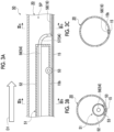
- Fig. 3A is a schematic sectional view showing a state of the treatment device 50 according to a modification example in a state of being disposed inside the metal pipe material 20.
- Fig. 3B is a sectional view taken along line IIIb-IIIb of Fig. 3A.
- Fig. 3C is a sectional view taken along line IIIc-IIIc of Fig. 3A .
- the injection nozzle 57 supplies the plating material 58 downward.
- the welded portion 15 of the metal pipe material 20 is also disposed on the lower end side of the metal pipe material 20.
- a pair of rollers 53 are provided with the welded portion 15 interposed therebetween when viewed in the axial direction on the lower end side of the rod 52 such that the rollers 53 and the welded portion 15 do not interfere with each other.
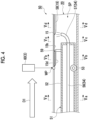
- Fig. 4 is a schematic sectional view showing a state of the treatment device 50 according to a modification example in a state of being disposed inside the metal pipe material 20.
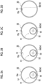
- Fig. 5A is a sectional view taken along line Va-Va of Fig. 4 .
- Fig. 5B is a sectional view taken along line Vb-Vb of Fig. 4 .
- Fig. 5C is a sectional view taken along line Vc-Vc of Fig. 4 .
- Fig. 5D is a sectional view taken along line Vd-Vd of Fig. 4 .
- the treatment device 50 further includes a cutting unit 59 that is provided on the upstream side of the location to which the plating material 58 is supplied by the supply unit 54, in the feed direction D1 of the metal pipe material 20, to cut the welded portion 15 from the inner periphery side of the metal pipe material 20.
- the supply unit 54 can immediately form the plating layer 19 on the inner periphery-side surface 15b of the welded portion 15.
- a welding nozzle 60 of the welding device 3 irradiates the outer periphery side of the metal pipe material 20 with a high frequency or the like, so that the abutted end portions 14a and 14a of the plate material 14 (refer to Fig. 5A ) are welded at a welding point WP.
- the position of the welding nozzle 60 is fixed in the feed direction D1. In this way, the upstream side of the welding point WP in the feed direction D1 becomes a region where the welded portion 15 is not formed, and the downstream side of the welding point WP in the feed direction D1 becomes a region where the welded portion 15 is formed.
- the welded portion 15 has the excess portion 15d having an excess thickness on the inner periphery side (also refer to Fig. 5B ).
- the cutting unit 59 is disposed at a position spaced from the welding point WP to the downstream side in the feed direction D1.
- the cutting unit 59 is configured with a blade member or the like, which protrudes upward from the upper end portion of the rod 52. In this way, the cutting unit 59 can cut the excess portion 15d protruding toward the inner periphery side of the welded portion 15. In this way, the inner periphery-side surface 15b of the welded portion 15 is formed (also refer to Fig. 5C ).
- the injection nozzle 57 injects the plating material 58 at a position spaced from the cutting unit 59 to the downstream side in the feed direction D1. In this way, the plating layer 19 is formed on the surface 15b after cutting (also refer to Fig. 5D ).
- the timing at which the treatment device 50 performs the plating treatment is not particularly limited.
- the metal pipe material 20 may be cut by the cutting device 4 and then subjected to the plating treatment by the treatment device 50.
- the treatment device 50 may be installed to a pipe-making apparatus in a retrofitting manner, so that there is an advantage that an existing pipe-making apparatus can be used as it is.
- the supply unit 54 supplies the plating material 58 by using the injection nozzle 57.
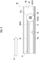
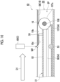
- the supply unit 54 may include a coating roller 157 instead of the injection nozzle 57, as shown in Figs. 8 , 9 , and 10 .
- Fig. 8 is a diagram showing a structure in which the coating roller 157 is applied to the treatment device 50 shown in Fig. 2A .
- the coating roller 157 is provided at the end portion of the rod 52.
- the coating roller 157 is a cylindrical member that is supported to be rotatable with a rotary shaft 158 as the center.
- the rotary shaft 158 is fixed to the rod 52.
- the coating roller 157 is not fixed with respect to the rod 52. Therefore, the coating roller 157 rotates around the rotary shaft 158 at the end portion of the rod 52.
- a portion of an outer peripheral surface 157a of the coating roller 157 is disposed at a position that is outside the rod 52 and close to the inner periphery-side surface 15b of the welded portion 15. Another portion of the outer peripheral surface 157a of the coating roller 157 is disposed at a position in the rod 52.
- the supply pipe 56 extends within the rod 52 to a position close to the outer peripheral surface 157a of the coating roller 157. In this way, the supply pipe 56 can supply the plating material 58 to the outer peripheral surface 157a of the coating roller 157 within the rod 52.
- the coating roller 157 rotates.
- the plating material 58 supplied from the supply pipe 56 adheres to the inner periphery-side surface 15b of the welded portion 15 as the outer peripheral surface 157a rotates.
- Fig. 9 is a drawing showing a configuration in which the coating roller 157 is applied to the treatment device 50 shown in Fig. 3A .
- Fig. 10 is a drawing showing a configuration in which the coating roller 157 is applied to the treatment device 50 shown in Fig. 4 .
- Each of the treatment devices 50 shown in Figs. 9 and 10 includes the coating roller 157 and the supply pipe 56 having the same configuration as in Fig. 8 .
Landscapes
- Engineering & Computer Science (AREA)
- Chemical & Material Sciences (AREA)
- Mechanical Engineering (AREA)
- Physics & Mathematics (AREA)
- Chemical Kinetics & Catalysis (AREA)
- Plasma & Fusion (AREA)
- Materials Engineering (AREA)
- Metallurgy (AREA)
- Organic Chemistry (AREA)
- General Engineering & Computer Science (AREA)
- Fluid Mechanics (AREA)
- Optics & Photonics (AREA)
- Coating With Molten Metal (AREA)
- Electroplating Methods And Accessories (AREA)
Abstract
Description
- The present invention relates to a treatment device, a treatment method, a method for manufacturing a metal pipe material, and a metal pipe material.
- In the related art, there is known a treatment device that performs treatment for forming a plating layer on a metal pipe material that is used as a material for hot forming. In this treatment device, a plating material is supplied to a welded portion of the metal pipe material from the outer periphery side (Al thermal spraying). Accordingly, in the treatment device, it is not possible to cover the outer periphery-side surface of the welded portion with a plating layer.
- [PTL 1]
Japanese Unexamined Patent Publication No. 07-3422 - A treatment device such as that of the related art described above can cover the surface of the welded portion with a plating layer from the outer periphery side. However, it is not possible to form a plating layer on the inner periphery-side surface of the welded portion. Accordingly, the inner periphery-side surface of the welded portion is exposed, so that there is a possibility that oxide scale may be generated on the surface.
- The present invention has been made to solve such a problem, and an object of the present invention is to provide a treatment device, a treatment method, a method for manufacturing a metal pipe material, and a metal pipe material, in which it is possible to manufacture a metal pipe material in which the generation of oxide scale can be suppressed.
- A treatment device according to an aspect of the present invention is a treatment device that performs treatment for forming a plating layer on a metal pipe material that is used as a material for hot forming, the treatment device including a supply unit that supplies a plating material to an inner periphery-side surface of a welded portion formed in the metal pipe material.
- The treatment device includes the supply unit that supplies the plating material to the inner periphery-side surface of the welded portion formed in the metal pipe material. In this way, the inner periphery-side surface of the welded portion of the metal pipe material is covered with the plating layer formed of the plating material. In this way, the welded portion can be prevented from being exposed on the inner periphery side of the metal pipe material. With the above, it is possible to manufacture the metal pipe material in which the generation of oxide scale can be suppressed.
- The treatment device may further include a cutting unit provided on an upstream side of a location to which the plating material is supplied by the supply unit, in a feed direction of the metal pipe material, to cut the welded portion from an inner periphery side of the metal pipe material. In this case, after an excess portion on the inner periphery side of the welded portion is removed by the cutting unit, the supply unit can immediately form a plating layer on the inner periphery-side surface of the welded portion.
- A treatment method according to an aspect of the present invention is a treatment method for performing treatment for forming a plating layer on a metal pipe material that is used as a material for hot forming, the treatment method including a process of supplying a plating material to an inner periphery-side surface of a welded portion formed in the metal pipe material.
- According to this treatment method, the same operation and effect as those of the treatment device described above can be obtained.
- A metal pipe material manufacturing method according to an aspect of the present invention is a method for manufacturing a metal pipe material from a plate material with a plating layer formed thereon, the method including performing, after end portions of the plate material are joined together by welding, plating treatment on a location where the plating layer has been peeled off due to the welding, of an inner peripheral surface of the metal pipe material.
- According to the method for manufacturing a metal pipe material, even in a case where the plating layer is peeled off due to joining the end portions of the plate material together by welding, the peeled location can be covered with the plating layer again by performing plating treatment on the peeled location. With the above, it is possible to manufacture the metal pipe material in which the generation of oxide scale can be suppressed.
- A metal pipe material according to an aspect of the present invention is a metal pipe material that is used as a material for hot forming, and in which an inner periphery-side surface of a welded portion is covered with a plating layer.
- According to this metal pipe material, the same operation and effect as those of the treatment device described above can be obtained.
- According to the present invention, it is possible to provide a treatment device, a treatment method, a method for manufacturing a metal pipe material, and a metal pipe material, in which it is possible to manufacture a metal pipe material in which the generation of oxide scale can be suppressed.
-
-
Fig. 1 is a schematic configuration diagram showing a schematic configuration of a metal pipe material manufacturing apparatus in which a treatment device according to an embodiment of the present invention is adopted. -
Fig. 2A is a schematic sectional view showing a state of a treatment device in a state of being disposed inside a metal pipe material,Fig. 2B is a sectional view taken along line IIb-IIb ofFig. 2A, and Fig. 2C is a sectional view taken along line IIc-IIc ofFig. 2A . -
Fig. 3A is a schematic sectional view showing a state of a treatment device according to a modification example in a state of being disposed inside a metal pipe material,Fig. 3B is a sectional view taken along line IIIb-IIIb ofFig. 3A, and Fig. 3C is a sectional view taken along line IIIc-IIIc ofFig. 3A . -
Fig. 4 is a schematic sectional view showing a state of a treatment device according to a modification example in a state of being disposed inside a metal pipe material. -
Fig. 5A is a sectional view taken along line Va-Va ofFig. 4 ,Fig. 5B is a sectional view taken along line Vb-Vb ofFig. 4 ,Fig. 5C is a sectional view taken along line Vc-Vc ofFig. 4 , andFig. 5D is a sectional view taken along line Vd-Vd ofFig. 4 . -
Fig. 6 is a perspective view of a metal pipe material according to an embodiment of the present invention. -
Fig. 7A is a diagram showing a metal pipe material as viewed from an axial direction,Fig. 7B is an enlarged diagram showing the state of the vicinity of a welded portion in a step before forming a plating layer, andFig. 7C is an enlarged diagram showing the state of the vicinity of the welded portion in a state where the plating layer has been formed. -
Fig. 8 is a schematic sectional view showing a state of a treatment device according to a modification example in a state of being disposed inside a metal pipe material. -
Fig. 9 is a schematic sectional view showing a state of a treatment device according to a modification example in a state of being disposed inside a metal pipe material. -
Fig. 10 is a schematic sectional view showing a state of a treatment device according to a modification example in a state of being disposed inside a metal pipe material. - Hereinafter, a preferred embodiment of the present invention will be described with reference to the drawings. In each drawing, identical or corresponding portions are denoted by the same reference numerals, and overlapping description is omitted.
-
Fig. 1 is a schematic configuration diagram showing a schematic configuration of a metal pipematerial manufacturing apparatus 100 in which atreatment device 50 according to an embodiment of the present invention is adopted. The metal pipematerial manufacturing apparatus 100 is an apparatus for manufacturing a metal pipe material that is used as a material for hot forming. As the hot forming that is used for a metal pipe material, for example, expansion forming can be given in which forming and quenching are simultaneously performed by placing a heated metal pipe material in a die and expanding it. In addition, hot forming such as induction quenching, hot bending forming, and hot drawing can be given. - Here, a
metal pipe material 20 will be described with reference toFig. 6 andFigs. 7A to 7C .Fig. 6 is a perspective view of themetal pipe material 20 according to the present embodiment.Figs. 7A to 7C are schematic diagrams for describing the states of a plating layer formed on themetal pipe material 20. As shown inFig. 6 , themetal pipe material 20 has a weldedportion 15 called a weld bead or the like, in whichend portions plate material 14 are welded together. More specifically, themetal pipe material 20 is formed by rounding a flat plate-shapedmetal plate material 14 into a cylindrical shape and welding theopposite end portions portion 15 in which themetal pipe material 20 is welded in this manner extends along a central axis L of themetal pipe material 20. The central axis L of themetal pipe material 20 is parallel to an extending direction D of themetal pipe material 20. -
Fig. 7A is a diagram showing themetal pipe material 20 as viewed from an axial direction.Fig. 7B is an enlarged diagram showing the state of the vicinity of the weldedportion 15 in a step before forming a plating layer.Fig. 7C is an enlarged diagram showing the state of the vicinity of the weldedportion 15 in a state where the plating layer has been formed.Figs. 7B and 7C are enlarged diagrams of an area surrounded by a dashed line circle inFig. 7A . As shown inFigs. 7B and 7C , aplating layer 16 is formed on the outer peripheral surface of themetal pipe material 20 so as to cover the entire outer peripheral surface. Further, aplating layer 17 is formed on the inner peripheral surface of themetal pipe material 20 so as to cover the entire inner peripheral surface. The plating layers 16 and 17 are originally formed on both surfaces of theplate material 14 in a step before theplate material 14 is rounded into a cylindrical shape. The plating layers 16 and 17 are formed by performing, for example, AlSi plating treatment on theplate material 14, which is a steel sheet. - As shown in
Fig. 7B , immediately after the weldedportion 15 is formed, a state is created where the plating layers 16 and 17 that have been originally present are peeled off at the location of the weldedportion 15. That is, the location of the weldedportion 15, of the outer peripheral surface of themetal pipe material 20, is a location where theplating layer 16 is peeled off due to welding. At this location, an outer periphery-side surface 15a of the weldedportion 15 is exposed. The location of the weldedportion 15, of the inner peripheral surface of themetal pipe material 20, is a location where theplating layer 17 is peeled off due to welding. At this location, an inner periphery-side surface 15b of the weldedportion 15 is exposed. - On the other hand, in the
metal pipe material 20 pertaining to a finished product, as shown inFig.7C , the outer periphery-side surface 15a of the weldedportion 15 is covered with aplating layer 18. The inner periphery-side surface 15b of the weldedportion 15 is covered with aplating layer 19. The plating layers 18 and 19 are formed to extend along the longitudinal direction of themetal pipe material 20 so as to fill the gaps of the plating layers 16 and 17. Theplating layer 18 on the outer periphery side is formed by performing Al thermal spraying on thesurface 15a of the weldedportion 15 from the outer periphery side of themetal pipe material 20. Theplating layer 19 on the inner periphery side is formed by the plating treatment using thetreatment device 50 which will be described later. - It returns to
Fig. 1 , and the metal pipematerial manufacturing apparatus 100 is described. As shown inFig. 1 , the metal pipematerial manufacturing apparatus 100 includes a plate material supply device 1, a formingdevice 2, awelding device 3, thetreatment device 50, and a cutting device 4. The plate material supply device 1 is a device for supplying the plate material 14 (refer toFig. 6 andFigs. 7A to 7C ), which is a precursor of themetal pipe material 20. The plate material supply device 1 supplies theplate material 14 in a flat plate state to the formingdevice 2. The plate material supply device 1 supplies theplate material 14 by rotating a roll body formed by winding a belt-shapedplate material 14 into a roll shape. The formingdevice 2 is a device for forming theplate material 14 into a cylindrical shape. The formingdevice 2 rounds the flat belt-shapedplate material 14 to form it in a cylindrical shape such that theend portions plate material 14 are abutted against each other. - The
welding device 3 is a device that welds the abutting portions of theend portions rounded plate material 14 to each other. In this way, the weldedportion 15 is formed along the longitudinal direction. Thewelding device 3 forms the weldedportion 15 by, for example, irradiating a welded location with a high frequency or the like. There is a case where the weldedportion 15 immediately after welding swells in the thickness direction from the inner peripheral surface or the outer peripheral surface of the metal pipe material 20 (for example, refer toFig. 4 (described later)). Therefore, thewelding device 3 includes a cutting mechanism for cutting the swelled portion of the weldedportion 15 immediately after welding. - The
treatment device 50 is a device that forms the plating layers 18 and 19 by performing plating treatment on the location of the weldedportion 15. Thetreatment device 50 includes a mechanism for forming theplating layer 18 on the outer periphery side, and a mechanism for forming theplating layer 19 on the inner periphery side. Details of the mechanism for forming theplating layer 19 on the inner periphery side will be described later. The cutting device 4 is a device for cutting themetal pipe material 20 to a desired length. By cutting with the cutting device 4, themetal pipe material 20 as shown inFig. 6 is completed. - Next, a specific configuration of the
treatment device 50 will be described with reference toFigs. 2A to 2C. Fig. 2A is a schematic sectional view showing a state of thetreatment device 50 in a state of being disposed inside themetal pipe material 20.Fig. 2B is a sectional view taken along line IIb-IIb ofFig. 2A. Fig. 2C is a sectional view taken along line IIc-IIc ofFig. 2A. Figs. 2A to 2C show an inner periphery-side platinglayer forming mechanism 51 for forming theplating layer 19 on the inner periphery side, of thetreatment device 50. A mechanism for forming theplating layer 18 on the outer periphery side, of thetreatment device 50, is omitted. InFigs. 2A to 2C , theplating layer 19 is shown to be thicker than the other plating layers in a deformed state. - As shown in
Fig. 2A , the inner periphery-side platinglayer forming mechanism 51 of thetreatment device 50 includes arod 52, aroller 53, and asupply unit 54. The platinglayer forming mechanism 51 is disposed in an internal space SP on the inner periphery side of themetal pipe material 20. Themetal pipe material 20 is disposed such that the longitudinal direction thereof is parallel to the horizontal direction. Further, themetal pipe material 20 is sent in a feed direction D1 in a state where the weldedportion 15 is disposed on the upper end side. Here, the platinglayer forming mechanism 51 is fixed so as not to move in the internal space of themetal pipe material 20. Therefore, themetal pipe material 20 moves toward the feed direction D1, so that themetal pipe material 20 moves relative to the platinglayer formation mechanism 51. - As shown in
Figs. 2A and 2B , therod 52 is disposed parallel to the longitudinal direction of themetal pipe material 20 within the internal space SP of themetal pipe material 20. Therod 52 is disposed on the lower end side of the internal space SP and disposed on the inner peripheral surface of the lower end portion of themetal pipe material 20 through theroller 53. In this way, when themetal pipe material 20 is sent in the feed direction D1, theroller 53 rotates while guiding themetal pipe material 20 in the feed direction D1. Therod 52 is configured with a cylindrical member. - As shown in
Fig. 2A , thesupply unit 54 supplies aplating material 58 for forming theplating layer 19 to the inner periphery-side surface 15b of the weldedportion 15 formed in themetal pipe material 20. In the present embodiment, thesupply unit 54 supplies Al paint as the platingmaterial 58. Specifically, thesupply unit 54 includes asupply pipe 56 that supplies theplating material 58, and aninjection nozzle 57 that injects the platingmaterial 58. Thesupply pipe 56 extends parallel to the longitudinal direction of therod 52 within therod 52. The platingmaterial 58 flows toward theinjection nozzle 57 side in thesupply pipe 56. Theinjection nozzle 57 injects the platingmaterial 58 supplied from thesupply pipe 56 toward the weldedportion 15 on the upper side. Theinjection nozzle 57 is connected to thesupply pipe 56 at the end portion in the longitudinal direction of therod 52. Theinjection nozzle 57 extends so as to be curved upward from the end portion of thesupply pipe 56. In this way, as shown inFig. 2C , the platingmaterial 58 is applied to the inner periphery-side surface 15b of the weldedportion 15, and theplating material 58 is dried to form theplating layer 19. - As the
plating material 58 that is supplied by thesupply unit 54, for example, paint obtained by mixing fine particles of Al and Si in an organic solvent may be adopted. In this paint, the organic solvent volatilizes in a heating process, and the remaining Al and Si components remain on the surface of an iron base material, so that it is possible to form a plating layer that can suppress the generation of oxide scale, like an AlSi plating material. - Next, the operation and effect of the
treatment device 50, a treatment method, a method for manufacturing themetal pipe material 20, and themetal pipe material 20 according to the present embodiment will be described. - The
treatment device 50 includes thesupply unit 54 that supplies theplating material 58 to the inner periphery-side surface 15b of the weldedportion 15 formed in themetal pipe material 20. In this way, the inner periphery-side surface 15b of the weldedportion 15 of themetal pipe material 20 is covered with theplating layer 19 formed of theplating material 58. In this way, the weldedportion 15 can be prevented from being exposed on the inner periphery side of themetal pipe material 20. With the above, it is possible to manufacture themetal pipe material 20 in which the generation of oxide scale can be suppressed. - The treatment method is a treatment method of performing treatment for forming the
plating layer 19 on themetal pipe material 20 that is used as a material for hot forming, the treatment method including a process of supplying theplating material 58 to the inner periphery-side surface 15b of the weldedportion 15 formed in themetal pipe material 20. - According to this treatment method, the same operation and effect as those of the
treatment device 50 device described above can be obtained. - The metal pipe material manufacturing method is a method for manufacturing the
metal pipe material 20 from theplate material 14 with theplating layer 17 formed thereon, the method including performing, after theend portions plate material 14 are joined together by welding, plating treatment on a location where theplating layer 17 has been peeled off due to the welding, of the inner peripheral surface of themetal pipe material 20. - According to the method for manufacturing the
metal pipe material 20, even in a case where theplating layer 17 is peeled off due to joining theend portions plate material 14 together by welding, the peeled location can be covered with theplating layer 19 again by performing plating treatment on the peeled location. With the above, it is possible to manufacture themetal pipe material 20 in which the generation of oxide scale can be suppressed. Further, it is possible to manufacture themetal pipe material 20 having high rust prevention performance. - As a method of preventing oxide scales, there is also a method of applying antirust paint to the entire bare
metal pipe material 20. However, in this method, it is difficult to evenly apply a plating material to the inner and outer surfaces, and the cost also increases. In contrast, thetreatment device 50 of the present embodiment performs treatment in a manner of repairing a partial location where the plating layer has been peeled off, and therefore, reliability is high, and the number of processes is not increased, so that the degree of increase in cost can also be kept small. - The
metal pipe material 20 is themetal pipe material 20 that is used as a material for hot forming, and in which the inner periphery-side surface 15b of the weldedportion 15 is covered with theplating layer 19. - According to the
metal pipe material 20, the same operation and effect as those of thetreatment device 50 device described above can be obtained. - The present invention is not limited to the embodiment described above.
- For example, the direction in which the
injection nozzle 57 of thesupply unit 54 supplies theplating material 58 is not particularly limited, and thetreatment device 50 as shown inFigs. 3A to 3C may be adopted.Fig. 3A is a schematic sectional view showing a state of thetreatment device 50 according to a modification example in a state of being disposed inside themetal pipe material 20.Fig. 3B is a sectional view taken along line IIIb-IIIb ofFig. 3A. Fig. 3C is a sectional view taken along line IIIc-IIIc ofFig. 3A . In thetreatment device 50 as shown inFigs. 3A to 3C , theinjection nozzle 57 supplies theplating material 58 downward. Accordingly, the weldedportion 15 of themetal pipe material 20 is also disposed on the lower end side of themetal pipe material 20. As shown inFig. 3B , a pair ofrollers 53 are provided with the weldedportion 15 interposed therebetween when viewed in the axial direction on the lower end side of therod 52 such that therollers 53 and the weldedportion 15 do not interfere with each other. - Further, the
treatment device 50 as shown inFig. 4 andFigs. 5A to 5D may be adopted.Fig. 4 is a schematic sectional view showing a state of thetreatment device 50 according to a modification example in a state of being disposed inside themetal pipe material 20.Fig. 5A is a sectional view taken along line Va-Va ofFig. 4 .Fig. 5B is a sectional view taken along line Vb-Vb ofFig. 4 .Fig. 5C is a sectional view taken along line Vc-Vc ofFig. 4 .Fig. 5D is a sectional view taken along line Vd-Vd ofFig. 4 . - As shown in
Fig. 4 , thetreatment device 50 further includes a cuttingunit 59 that is provided on the upstream side of the location to which theplating material 58 is supplied by thesupply unit 54, in the feed direction D1 of themetal pipe material 20, to cut the weldedportion 15 from the inner periphery side of themetal pipe material 20. In this case, after anexcess portion 15d on the inner periphery side of the weldedportion 15 is removed by the cuttingunit 59, thesupply unit 54 can immediately form theplating layer 19 on the inner periphery-side surface 15b of the weldedportion 15. - As shown in
Fig. 4 , awelding nozzle 60 of thewelding device 3 irradiates the outer periphery side of themetal pipe material 20 with a high frequency or the like, so that theabutted end portions Fig. 5A ) are welded at a welding point WP. The position of thewelding nozzle 60 is fixed in the feed direction D1. In this way, the upstream side of the welding point WP in the feed direction D1 becomes a region where the weldedportion 15 is not formed, and the downstream side of the welding point WP in the feed direction D1 becomes a region where the weldedportion 15 is formed. Here, immediately after the welding is performed at the welding point WP, the weldedportion 15 has theexcess portion 15d having an excess thickness on the inner periphery side (also refer toFig. 5B ). On the other hand, the cuttingunit 59 is disposed at a position spaced from the welding point WP to the downstream side in the feed direction D1. The cuttingunit 59 is configured with a blade member or the like, which protrudes upward from the upper end portion of therod 52. In this way, the cuttingunit 59 can cut theexcess portion 15d protruding toward the inner periphery side of the weldedportion 15. In this way, the inner periphery-side surface 15b of the weldedportion 15 is formed (also refer toFig. 5C ). Theinjection nozzle 57 injects the platingmaterial 58 at a position spaced from the cuttingunit 59 to the downstream side in the feed direction D1. In this way, theplating layer 19 is formed on thesurface 15b after cutting (also refer toFig. 5D ). - Further, in the embodiment described above, a pipe-making apparatus in which the
metal pipe material 20 is subjected to the plating treatment by thetreatment device 50 after thewelding device 3 and then is cut by the cutting device 4 has been described. However, the timing at which thetreatment device 50 performs the plating treatment is not particularly limited. For example, after welding by thewelding device 3, themetal pipe material 20 may be cut by the cutting device 4 and then subjected to the plating treatment by thetreatment device 50. In this case, even in a case where it is difficult to install a new pipe-making apparatus or a case where it is difficult to modify an existing pipe-making apparatus, thetreatment device 50 may be installed to a pipe-making apparatus in a retrofitting manner, so that there is an advantage that an existing pipe-making apparatus can be used as it is. - In the embodiment and modification examples described above, the
supply unit 54 supplies theplating material 58 by using theinjection nozzle 57. Thesupply unit 54 may include acoating roller 157 instead of theinjection nozzle 57, as shown inFigs. 8 ,9 , and10 . Specifically,Fig. 8 is a diagram showing a structure in which thecoating roller 157 is applied to thetreatment device 50 shown inFig. 2A . As shown inFig. 8 , thecoating roller 157 is provided at the end portion of therod 52. Thecoating roller 157 is a cylindrical member that is supported to be rotatable with arotary shaft 158 as the center. Therotary shaft 158 is fixed to therod 52. Thecoating roller 157 is not fixed with respect to therod 52. Therefore, thecoating roller 157 rotates around therotary shaft 158 at the end portion of therod 52. - A portion of an outer
peripheral surface 157a of thecoating roller 157 is disposed at a position that is outside therod 52 and close to the inner periphery-side surface 15b of the weldedportion 15. Another portion of the outerperipheral surface 157a of thecoating roller 157 is disposed at a position in therod 52. Thesupply pipe 56 extends within therod 52 to a position close to the outerperipheral surface 157a of thecoating roller 157. In this way, thesupply pipe 56 can supply theplating material 58 to the outerperipheral surface 157a of thecoating roller 157 within therod 52. When themetal pipe material 20 is fed in the feed direction D1, thecoating roller 157 rotates. As a result, the platingmaterial 58 supplied from thesupply pipe 56 adheres to the inner periphery-side surface 15b of the weldedportion 15 as the outerperipheral surface 157a rotates. -
Fig. 9 is a drawing showing a configuration in which thecoating roller 157 is applied to thetreatment device 50 shown inFig. 3A .Fig. 10 is a drawing showing a configuration in which thecoating roller 157 is applied to thetreatment device 50 shown inFig. 4 . Each of thetreatment devices 50 shown inFigs. 9 and10 includes thecoating roller 157 and thesupply pipe 56 having the same configuration as inFig. 8 . -
- 14
- Plate material
- 15
- Welded portion
- 17, 19
- Plating layer
- 20
- Metal pipe material
- 50
- Treatment device
- 54
- Supply unit
- 58
- Plating material
- 59
- Cutting unit
Claims (5)
- A treatment device that performs treatment for forming a plating layer on a metal pipe material that is used as a material for hot forming, the treatment device comprising:
a supply unit that supplies a plating material to an inner periphery-side surface of a welded portion formed in the metal pipe material. - The treatment device according to claim 1, further comprising:
a cutting unit provided on an upstream side of a location to which the plating material is supplied by the supply unit, in a feed direction of the metal pipe material, to cut the welded portion from an inner periphery side of the metal pipe material. - A treatment method for performing treatment for forming a plating layer on a metal pipe material that is used as a material for hot forming, the treatment method comprising:
a process of supplying a plating material to an inner periphery-side surface of a welded portion formed in the metal pipe material. - A method for manufacturing a metal pipe material from a plate material with a plating layer formed thereon, the method comprising:
performing, after end portions of the plate material are joined together by welding, plating treatment on a location where the plating layer has been peeled off due to the welding, of an inner peripheral surface of the metal pipe material. - A metal pipe material that is used as a material for hot forming,
wherein an inner periphery-side surface of a welded portion is covered with a plating layer.
Applications Claiming Priority (2)
| Application Number | Priority Date | Filing Date | Title |
|---|---|---|---|
| JP2020148328 | 2020-09-03 | ||
| PCT/JP2021/030646 WO2022050091A1 (en) | 2020-09-03 | 2021-08-20 | Treatment device, treatment method, method for manufacturing metal pipe material, and metal pipe material |
Publications (2)
| Publication Number | Publication Date |
|---|---|
| EP4209615A1 true EP4209615A1 (en) | 2023-07-12 |
| EP4209615A4 EP4209615A4 (en) | 2023-07-19 |
Family
ID=80490850
Family Applications (1)
| Application Number | Title | Priority Date | Filing Date |
|---|---|---|---|
| EP21864149.6A Pending EP4209615A4 (en) | 2020-09-03 | 2021-08-20 | Treatment device, treatment method, method for manufacturing metal pipe material, and metal pipe material |
Country Status (7)
| Country | Link |
|---|---|
| US (1) | US20230160050A1 (en) |
| EP (1) | EP4209615A4 (en) |
| JP (1) | JPWO2022050091A1 (en) |
| KR (1) | KR20230061293A (en) |
| CN (1) | CN115956137A (en) |
| CA (1) | CA3189002A1 (en) |
| WO (1) | WO2022050091A1 (en) |
Family Cites Families (10)
| Publication number | Priority date | Publication date | Assignee | Title |
|---|---|---|---|---|
| JPS5014544A (en) * | 1973-06-12 | 1975-02-15 | ||
| CH684524A5 (en) * | 1991-12-17 | 1994-10-14 | Ernst M Frey | Weld on the inside cover of sheet metal pipes. |
| JPH06166118A (en) * | 1992-11-30 | 1994-06-14 | Sekisui Chem Co Ltd | Manufacturing method of composite pipe |
| JPH073422A (en) | 1993-05-25 | 1995-01-06 | Nisshin Steel Co Ltd | Method for repairing machined weld bead zone of al-plated electric resistance welded tube |
| JP3667840B2 (en) * | 1995-11-06 | 2005-07-06 | 株式会社フジクラ | Manufacturing method of heat exchange pipe |
| JP2000084462A (en) * | 1998-09-11 | 2000-03-28 | Japan Steel & Tube Constr Co Ltd | Pipe interior cleaning apparatus, pipe interior coating apparatus and method |
| JP2003013196A (en) * | 2001-06-29 | 2003-01-15 | Otis:Kk | Metal pipe |
| CN2587575Y (en) * | 2002-12-19 | 2003-11-26 | 昌德机电(天津)有限公司 | Cooling water spraying structure for pearl removing machine in guide pipe welding |
| JPWO2006054350A1 (en) * | 2004-11-18 | 2008-08-07 | 大和鋼管工業株式会社 | Manufacturing method of sprayed metal plated steel pipe |
| JP6926927B2 (en) * | 2017-10-18 | 2021-08-25 | 日本製鉄株式会社 | Manufacturing method of Al-plated steel pipe parts and Al-plated steel pipe parts |
-
2021
- 2021-08-20 WO PCT/JP2021/030646 patent/WO2022050091A1/en not_active Ceased
- 2021-08-20 JP JP2022546233A patent/JPWO2022050091A1/ja not_active Withdrawn
- 2021-08-20 CA CA3189002A patent/CA3189002A1/en active Pending
- 2021-08-20 KR KR1020227043159A patent/KR20230061293A/en not_active Withdrawn
- 2021-08-20 CN CN202180042588.5A patent/CN115956137A/en active Pending
- 2021-08-20 EP EP21864149.6A patent/EP4209615A4/en active Pending
-
2023
- 2023-01-10 US US18/152,750 patent/US20230160050A1/en not_active Abandoned
Also Published As
| Publication number | Publication date |
|---|---|
| WO2022050091A1 (en) | 2022-03-10 |
| US20230160050A1 (en) | 2023-05-25 |
| CA3189002A1 (en) | 2022-03-10 |
| EP4209615A4 (en) | 2023-07-19 |
| CN115956137A (en) | 2023-04-11 |
| KR20230061293A (en) | 2023-05-08 |
| JPWO2022050091A1 (en) | 2022-03-10 |
Similar Documents
| Publication | Publication Date | Title |
|---|---|---|
| CA2786460C (en) | Induction heating coil, and an apparatus and method for manufacturing a worked member | |
| US11911836B2 (en) | Method for applying a reinforcement of metal material to a component of metal material, particularly in the construction of a motor-vehicle body or a sub-assembly thereof | |
| JP2010539326A (en) | Method and apparatus for curing profiles | |
| US20160082492A1 (en) | Method for producing a multi-layer large pipe | |
| JP2000130651A (en) | Multi-wall pipe | |
| US20230160050A1 (en) | Treatment device, treatment method, method for manufacturing metal pipe material, and metal pipe material | |
| EP2841232B1 (en) | Flux cored wire and manufacturing method thereof and manufacturing device thereof | |
| EP2863268B1 (en) | Developing device, blade unit, and developing device manufacturing method | |
| JP2010502859A (en) | Roller body manufacturing method and roller body | |
| KR102005168B1 (en) | Method and coating apparatus for applying cladding layer during multi-layer heavy-duty pipe fabrication | |
| JP2002242779A (en) | Manufacturing method for fuel inlet | |
| CN101903595A (en) | Process for the manufacture of metal strips for use in paper/board machines or finishing machines | |
| US4499643A (en) | Process for manufacturing a piston ring | |
| JP2006289439A (en) | Method and apparatus for expanding UOE steel pipe | |
| US7111770B2 (en) | Method for producing connecting ends on metal tubes and tube piece comprising such connecting ends | |
| JP4645853B2 (en) | Method of deforming cross section of coated metal plate by laser beam and painted metal plate having this kind of cross section deformation | |
| JP2000271639A (en) | Plated steel tube and its manufacture | |
| US20180354063A1 (en) | Ultrasonic welding of annular components | |
| WO2003010356A1 (en) | Method for manufacturing pipe formed product and pipe formed product | |
| WO2022050089A1 (en) | Method for joining dissimilar materials, and rivet used in same | |
| US20250187101A1 (en) | Method and apparatus for mitigating risk of liquid metal embrittlement during resistance welding | |
| GB2124331A (en) | Manufacturing piston rings with inserts | |
| RU2262426C1 (en) | Metal-polymer tube ultrasonic seam welding method | |
| JP4726793B2 (en) | Structured metal plate manufacturing method and apparatus for exhaust gas treatment equipment | |
| JP4483215B2 (en) | Manufacturing method of welded section steel |
Legal Events
| Date | Code | Title | Description |
|---|---|---|---|
| STAA | Information on the status of an ep patent application or granted ep patent |
Free format text: STATUS: THE INTERNATIONAL PUBLICATION HAS BEEN MADE |
|
| PUAI | Public reference made under article 153(3) epc to a published international application that has entered the european phase |
Free format text: ORIGINAL CODE: 0009012 |
|
| REG | Reference to a national code |
Ref country code: DE Ref legal event code: R079 Free format text: PREVIOUS MAIN CLASS: C23C0024080000 Ipc: B21D0026033000 |
|
| STAA | Information on the status of an ep patent application or granted ep patent |
Free format text: STATUS: REQUEST FOR EXAMINATION WAS MADE |
|
| STAA | Information on the status of an ep patent application or granted ep patent |
Free format text: STATUS: EXAMINATION IS IN PROGRESS |
|
| 17P | Request for examination filed |
Effective date: 20230111 |
|
| AK | Designated contracting states |
Kind code of ref document: A1 Designated state(s): AL AT BE BG CH CY CZ DE DK EE ES FI FR GB GR HR HU IE IS IT LI LT LU LV MC MK MT NL NO PL PT RO RS SE SI SK SM TR |
|
| A4 | Supplementary search report drawn up and despatched |
Effective date: 20230615 |
|
| RIC1 | Information provided on ipc code assigned before grant |
Ipc: B05D 7/14 20060101ALI20230609BHEP Ipc: F16L 58/04 20060101ALI20230609BHEP Ipc: F16L 9/17 20060101ALI20230609BHEP Ipc: C23C 4/08 20160101ALI20230609BHEP Ipc: B05D 7/22 20060101ALI20230609BHEP Ipc: B05D 1/02 20060101ALI20230609BHEP Ipc: B05C 7/02 20060101ALI20230609BHEP Ipc: B05C 7/00 20060101ALI20230609BHEP Ipc: C23C 2/12 20060101ALI20230609BHEP Ipc: B23K 37/08 20060101ALI20230609BHEP Ipc: B23D 1/24 20060101ALI20230609BHEP Ipc: B21D 26/033 20110101AFI20230609BHEP |
|
| 17Q | First examination report despatched |
Effective date: 20230627 |
|
| DAV | Request for validation of the european patent (deleted) | ||
| DAX | Request for extension of the european patent (deleted) |